

Page 1

- Data Brochure
D 040
Remote Display Module (RDM) 040
05/07
The tekmar Remote Display Module (RDM) 040 provides the user with a remote interface to
any tekmar control that is tekmar NetTM (tN2) capable. The RDM can be used to view and / or
adjust the settings on the control that it is connected to, or on any Room Temperature Unit
(RTU) that may be connected to the control. The RDM can display any of the system and
status indicators visible on the control or RTU. It also has a built in alarm contact that can be
used to trigger an external alarm if either a control or sensor error occurs.
Installation
STEP ONE
Place a screwdriver or similar object into the small slot located in the top of the RDM. Push
the screwdriver against the plastic tab, and pull the top of the front cover so that it pivots
around the bottom edge of the RDM.
STEP TWO
The base of the RDM should be securely installed in
the desired location. Mount the RDM directly to the
desired location using two #6-1” screws. The screws
are inserted through the mounting holes and must be
securely fastened to the desired location. If possible,
at least one of the screws should enter a wall stud or
similar surface. If the RDM is to be mounted to a 2” x
4” electrical box, order an Adaptor Plate 007. This plate
mounts to the electrical box and the RDM will then
mount to the plate.
REMOVING THE FRONT COVER
MOUNTING THE RDM
To Control
#6 1” screws
STEP THREE
WIRING THE RDM
Run 18 AWG twisted pair or similar wire between the RDM and
the control. Insert the wires through the hole provided in the
3
2
1
Wa
rn
in
4
Com
tN2
g
back of the RDM enclosure and connect them to the Com and
the tekmar NetTM (TN2) terminals. Do not run the wires parallel to
telephone or power lines as this may interfere with the operation
of the RDM. If the RDM wires are located in an area with strong
sources of electromagnetic noise, shielded cable should be used
or the wires can be run in a grounded metal conduit.
NOTE: Do not apply power to the RDM. The RDM is to be wired directly to the control. The
connection between the control and the RDM is polarity sensitive. The Com terminal of
the RDM must be connected to the Com terminal of the control and the tekmarNetTM (tN2)
terminal of the RDM must be connected to the appropriate terminal of the control. If the
wires are reversed, the display on the RDM will remain blank and the control will display a
short circuit error for the tekmarNetTM (tN2) device.
1 of 4 © 2007 D 040 - 05/07
Page 2
STEP FOUR
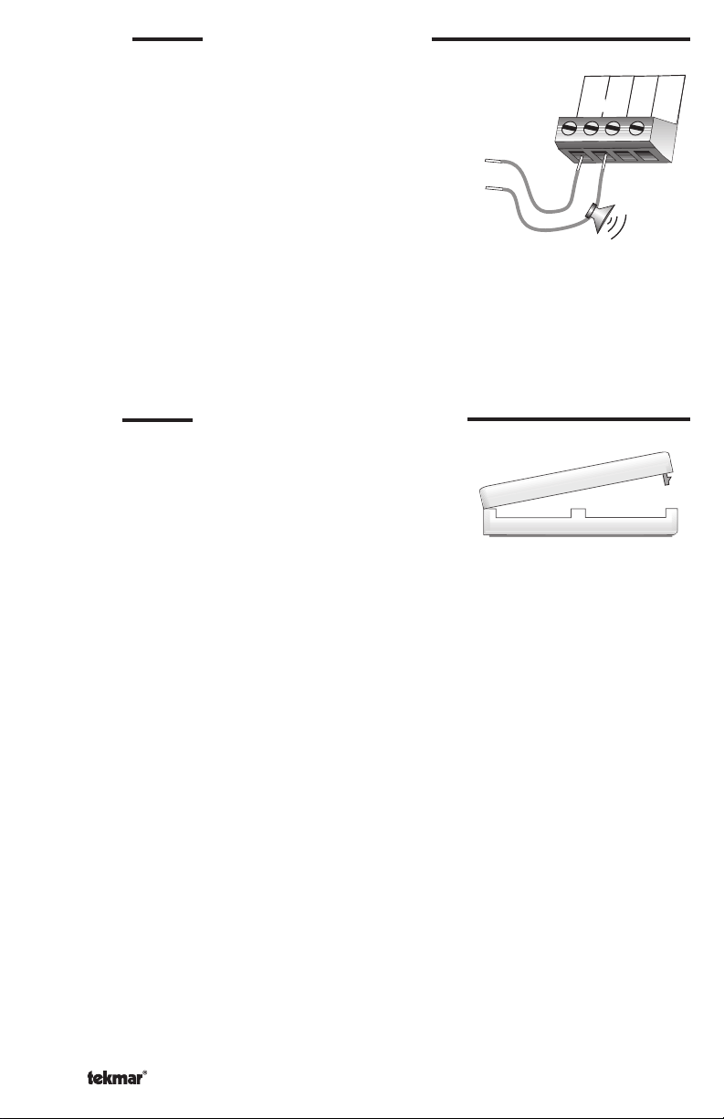
WIRING A REMOTE ALARM
The RDM comes with a built in alarm contact. This
contact will close anytime either a sensor or control error
is detected by the control. The contact will remain closed
Warning
3
2
1
tN
2
until the error is cleared. To clear the error message on
the RDM and turn off the alarm relay, refer to the control
Data Brochure. This contact will also close if a Warning in
the control is triggered. However, if a warning is triggered,
the alarm contact will only remain closed for 60 seconds.
24 V(ac or dc)
24 V(ac)
Low Voltage
Alarm
After 60 seconds, the warning message will continue to be
displayed, but the alarm contact will be shut off. To clear
the warning message, the keypad of the RDM must be
pressed as described in the control Data Brochure.
Between terminals 1 and 2, the contact is capable of switching a low voltage signal that
is less than 0.5 Amps. This switch can be used to operate a low voltage alarm device
directly, or it can be used to energize an external relay to trigger a line voltage or high
current alarm device.
4
Com
STEP FIVE
INSTALLING THE FRONT COVER
Align the hinges on the bottom of the front cover with the
bottom of the RDM mounting base. Pivot the front cover
around the bottom hinges and push the top against the
mounting base until it snaps firmly in place.
r
e
v
o
c
t
n
o
r
f
e
h
t
g
n
i
l
l
a
t
s
n
I
© 2007 D 040 - 05/07 2 of 4
Page 3

Settings
•
•
•
SELECTING THE DEVICE
The RDM can be used to view and / or adjust any of the settings on either the control or
any of the RTU’s connected to the control.
The device that is to be viewed or adjusted is selected as follows:
• Select the Miscellaneous (Misc) Menu by pressing the Menu button.
• Press the Item button until the word DEVICE is displayed in the LCD.
• Use the Up and Down buttons to select either the Control (CTRL) or one of the
RTU’s (RTU1, RTU2, ...).
Once the device has been selected, the RDM can be used to view and / or adjust the
settings of the selected device.
TEMPERATURE UNITS
The RDM is capable of displaying the temperature in either °F or °C. In order to select the
temperature units, press the Menu button until the Miscellaneous (Misc) menu is displayed.
Next, press the Item button until the UNITS item is displayed. Then use the Up or Down
button to select the desired units of measure.
ACCESS LEVELS
The RDM has four access levels that restrict the number of Menus, Items, and Adjustments
that can be accessed by the user. The four access levels are Limited (LTD), User (USER),
Installer (INST), and Advanced (ADV).
The access level of the RDM is found in the Miscellaneous (Misc) menu. The access level
can only be viewed and / or adjusted when the Lock / Unlock DIP switch of the control that
the RDM is connected to is set to the Unlock position. To determine if the RDM’s access
level is currently locked or unlocked, a small segment representing a padlock is viewed in
the bottom right hand corner of the display.
3 of 4 © 2007 D 040 - 05/07
Page 4

Technical Data
REMOTE DISPLAY MODULE (RDM) 040
Literature D 040
Packaged weight 0.22 lb. (100 g), Enclosure J, white PVC plastic
Dimensions 2-7/8” H x 2-7/8” W x 13/16” D (73 x 73 x 21 mm)
Approvals CSA NRTL/C, meets DOC & FCC regulations for EMI/RFI.
Ambient conditions Indoor use only, 32 to 122°F (0 to 50°C), < 90% RH non-condensing
Power Supply tekmar control; tekmar Net 2 (tN2)
Relay 24 V (ac or dc) 0.5 A, pilot duty 6 VA
Limited Warranty and Product Return Procedure
Limited Warranty The liability of tekmar under this warranty is limited. The Purchaser, by taking receipt of
any tekmar product (“Product”), acknowledges the terms of the Limited Warranty in effect at the time of
such Product sale and acknowledges that it has read and understands same.
The tekmar Limited Warranty to the Purchaser on the Products sold hereunder is a manufacturer’s passthrough warranty which the Purchaser is authorized to pass through to its customers. Under the Limited
Warranty, each tekmar Product is warranted against defects in workmanship and materials if the Product
is installed and used in compliance with tekmar’s instructions, ordinary wear and tear excepted. The passthrough warranty period is for a period of twenty-four (24) months from the production date if the Product is
not installed during that period, or twelve (12) months from the documented date of installation if installed
within twenty-four (24) months from the production date.
The liability of tekmar under the Limited Warranty shall be limited to, at tekmar’s sole discretion: the cost of parts
and labor provided by tekmar to repair defects in materials and / or workmanship of the defective product; or to
the exchange of the defective product for a warranty replacement product; or to the granting of credit limited to the
original cost of the defective product, and such repair, exchange or credit shall be the sole remedy available from
tekmar, and, without limiting the foregoing in any way, tekmar is not responsible, in contract, tort or strict product
liability, for any other losses, costs, expenses, inconveniences, or damages, whether direct, indirect, special, secondary, incidental or consequential, arising from ownership or use of the product, or from defects in workmanship
or materials, including any liability for fundamental breach of contract.
The pass-through Limited Warranty applies only to those defective Products returned to tekmar during the warranty period. This Limited Warranty does not cover the cost of the parts or labor to remove or transport the defective Product, or to reinstall the repaired or replacement Product, all such costs and expenses being subject to
Purchaser’s agreement and warranty with its customers.
Any representations or warranties about the Products made by Purchaser to its customers which are different from
or in excess of the tekmar Limited Warranty are the Purchaser’s sole responsibility and obligation. Purchaser shall
indemnify and hold tekmar harmless from and against any and all claims, liabilities and damages of any kind or
nature which arise out of or are related to any such representations or warranties by Purchaser to its customers.
The pass-through Limited Warranty does not apply if the returned Product has been damaged by negligence by
persons other than tekmar, accident, fire, Act of God, abuse or misuse; or has been damaged by modifications,
alterations or at tachments made subsequent to purchase which have not been authorized by tekmar; or if the Product was not installed in compliance with tekmar’s instructions and / or the local codes and ordinances; or if due to
defective installation of the Product; or if the Product was not used in compliance with tekmar’s instructions.
THIS WARRANTY IS IN LIEU OF ALL OTHER WARRANTIES, EXPRESS OR IMPLIED, WHICH THE GOVERNING
LAW ALLOWS PARTIES TO CONTRACTUALLY EXCLUDE, INCLUDING, WITHOUT LIMITATION, IMPLIED WARRANTIES OF MERCHANTABILITY AND FITNESS FOR A PARTICULAR PURPOSE, DURABILITY OR DESCRIPTION OF THE PRODUCT, ITS NON-INFRINGEMENT OF ANY RELEVANT PATENTS OR TRADEMARKS, AND
ITS COMPLIANCE WITH OR NON-VIOLATION OF ANY APPLICABLE ENVIRONMENTAL, HEALTH OR SAFETY
LEGISLATION; THE TERM OF ANY OTHER WARRANTY NOT HEREBY CONTRACTUALLY EXCLUDED IS LIMITED SUCH THAT IT SHALL NOT EXTEND BEYOND TWENTY-FOUR (24) MONTHS FROM THE PRODUCTION
DATE, TO THE EXTENT THAT SUCH LIMITATION IS ALLOWED BY THE GOVERNING LAW.
Product Warranty Return Procedure All Products that are believed to have defects in workmanship or materials must be returned, together with a written description of the defect, to the tekmar Representative assigned to
the territory in which such Product is located. If tekmar receives an inquiry from someone other than a tekmar
Representative, including an inquiry from Purchaser (if not a tekmar Representative) or Purchaser’s customers,
regarding a potential warranty claim, tekmar’s sole obligation shall be to provide the address and other contact
information regarding the appropriate Representative.
tekmar Control Systems Ltd., Canada
tekmar Control Systems, Inc., U.S.A.
Head Office: 5100 Silver Star Road
Vernon, B.C. Canada V1B 3K4
(250) 545-7749 Fax. (250) 545-0650
Web Site: www.tekmarcontrols.com
All specifications are subject
to change without notice
Product design, software and literature
are Copyright © 2007 by:
tekmar Control Systems Ltd. and tekmar
Control Systems, Inc.
4 of 4 D 040 - 05/07.
 Loading...