

Page 1
English Manual
Reveal 402 / 502 / 802
Page 2

Page 3
English manual
10. Protect the power cord from being walked on
English manual
Important safety instructions
1. Read these instructions.
2. Keep these instructions.
3. Heed all warnings.
4. Follow all instructions.
5. Do not use this apparatus near water.
6. Clean only with a dry cloth.
7. Do not block any ventilation openings. Install
in accordance with the manufacturer’s instructions.
8. Do not install near any heat sources such as radiators, heat registers, stoves, or other apparatus (including amplifiers) that produce heat.
9. Do not defeat the safety purpose of the polarized or grounding-type plug. A polarized plug
has two blades with one wider than the other. A
grounding-type plug has two blades and a third
grounding prong. The wide blade or the third
prong is provided for your safety. If the provided plug does not fit into your outlet, consult an
electrician for replacement of the obsolete outlet.
or pinched, particularly at plugs, convenience
receptacles, and the point where they exit from
the apparatus.
11. Only use attachments/accessories specified by
the manufacturer.
12. Use only with a cart, stand, tripod,
bracket, or table specified by the
manufacturer, or sold with the apparatus. When a cart is used, use caution when moving the cart/apparatus
combination to avoid injury from tip-over.
13. Unplug this apparatus during lightning storms or
when unused for long periods of time.
14. Refer all servicing to qualified service personnel. Servicing is required when the apparatus
has been damaged in any way, such as powersupply cord or plug is damaged, liquid has been
spilled or objects have fallen into the apparatus,
the apparatus has been exposed to rain or moisture, does not operate normally, or has been
dropped.
Explanation of graphic symbols
The lightning bolt triangle is used to alert
the user to the presence of uninsulated
“dangerous voltages” within the unit’s
chassis that may be of sufficient magni-
English manual 1
Page 4

Important safety instructions
tude to constitute a risk of electric shock
to humans.
The exclamation point triangle is used to
alert the user to presence of important operating and service instructions in the literature accompanying the product.
Warning
– Voltages in this equipment are hazardous to
life. Do not open the unit – risk of electric shock
inside. There are no user-serviceable parts inside.
Refer all servicing to qualified service personnel.
– Make sure that the “Voltage Select” switch on the
rear panel is set correctly for your area before connecting the mains plug.
– Use only with the detachable power cord supplied
with the apparatus, or by your local distributor or
dealer.
– The MAINS plug is used as the disconnect device
and shall remain readily operable.
– To reduce the risk of fire or electric shock, do not
expose this apparatus to rain or moisture and objects filled with liquids, such as vases, should not
be placed on this apparatus.
– Do not install this device in a confined space.
Fuse protection
A mains fuse is provided in the IEC power inlet on
the back of this apparatus, which can only be removed with the power cord unplugged. This must be
replaced by a fuse of the same type and rating (see
specifications or refer to rear panel).
Warning: Strong magnetic field
Due to the powerful drive unit magnet, do not place
within 1 meter (3 foot) of a cathode ray tube (CRT)
television or monitor. There is no issue with plasma,
LCD and LCD devices.
EMC / EMI
Electromagnetic compatibility /
Electromagnetic interference
This device has undergone safety and EMC testing,
and complies with the European Low Voltage Directive 20 06 / 95 / EC a nd Elec tromagnetic Compatibility
Directive 2004 / 108 / EC.
This equipment has been tested and found to comply
with the limits for a Class B digital device, pursuant
to part 15 of the FCC rules. These limits are designed
to provide reasonable protection against harmful interference in residential installations. This equipment
generates, uses and can radiate radio frequency en-
2 Reveal 402 / 502 / 802
Page 5

Warranty
ergy and, if not installed and used in accordance with
the instructions, may cause harmful interference to
radio communications. However, there is no guarantee that interference will not occur in a particular installation.
If this equipment does cause harmful interference
to radio or television reception, which can be determined by turning the equipment off and on, the user
is encouraged to try to correct the interference by one
or more of the following measures:
– Reorient or relocate the receiving antenna.
– Increase the separation between the equipment
and receiver.
– Connect the equipment into an outlet on a circuit
different from that to which the receiver is connected.
– Consult the dealer or an experienced radio/TV
technician for help.
Changes or modifications not expressly approved
by Tannoy Ltd. for compliance could void the user’s authority to operate the equipment.
Warranty
No maintenance of the loudspeaker is necessary.
Please register your Tannoy product online at
www.tannoy.com.
All of our products have been produced and tested
with care and precision to give first-class service.
All passive components are guaranteed for a period
of 5 years from the date of purchase from an authorized Tannoy dealer subject to the absence of accident, misuse, neglect, unauthorized modification or
fair wear and tear.
All active and electronic components are guaranteed
for a period of 2 years from the date of purchase from
an authorized Tannoy dealer. If at any time during this
warranty period the equipment proves to be defective
for any reason other than accident, misuse, neglect,
unauthorized modification or fair wear and tear, we
will repair any such manufacturing defect or, at our
option, replace it without charge for labour, parts or
return carriage.
If you suspect a problem with a Tannoy product, in
the first instance, discuss it with your Tannoy dealer.
English manual 3
Page 6

Introduction
If you require further assistance then we ask that you
deal directly with your local Tannoy distributor. If you
cannot locate your distributor please contact Tannoy
Customer Services, at the address given below.
Tannoy Ltd. UK
Customer Services
Rosehall Industrial Estate
Coatbridge
North Lanarkshire
ML5 4TF
Scotland
United Kingdom
Telephone: +44 1236 420199
Fax: +44 1236 428230
E-mail: enquiries@tannoy.com
Do not ship any product to Tannoy without previous authorization.
Our policy commits us to incorporating improvements
to our products through continuous research and development. Please confirm current specifications for
critical applications with your supplier.
Introduction
Once you have set up your new loudspeakers as described in this manual, please complete and return
the registration document or register you product
online at www.tannoy.com – this does not limit your
legal rights.
Unpacking
Check carefully for any sign of transit damage. In the
unlikely event of transit damage, notify your shipping
company and / or dealer as soon as possible for advice. It is recommended you store all packaging to allow protected transport in future.
Ensure that the following accessories are present:
– mains cord appropriate to your country of use
– one 5 meter 3.5 mm mini-jack cable.
Caution
These loudspeakers are capable of generating
high sound levels over a sustained period of time.
Because of their low levels of distortion, it is not always obvious that the sound level is high when working with these loudspeakers. Please be aware that exposure to excessive levels over a sustained period of
time can lead to permanent hearing damage.
4 Reveal 402 / 502 / 802
Page 7
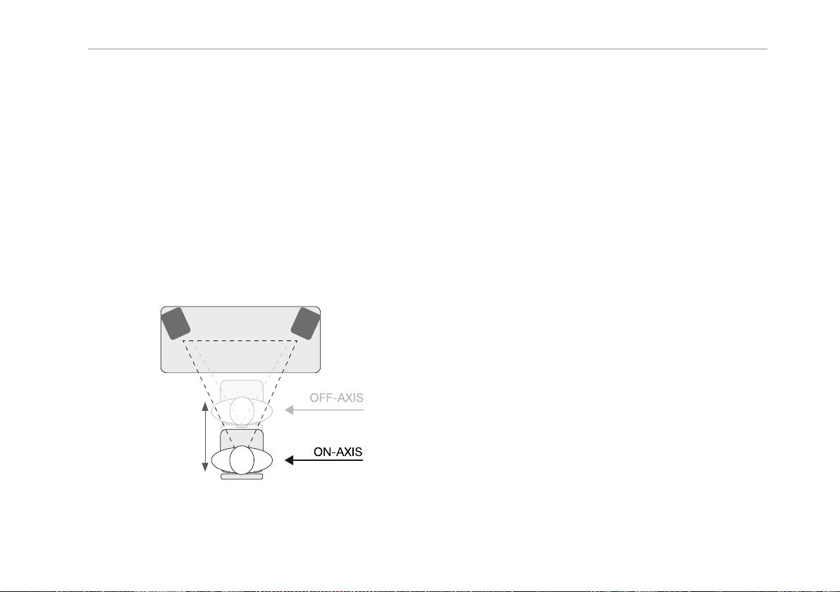
Positioning your speakers
Positioning your speakers
These loudspeakers are designed as near field monitors, positioned typically 0.75 to 3 meters from the listener. They will typically be placed on the mixer metering bridge or on a table either side of a smaller mixing
desk or control surface. They may also be mounted
on appropriate loudspeaker stands, which will yield
the best results in terms of stability and vibration. In all
cases, these speakers should be angled towards the
listener, with the tweeter approximately at ear height.
For best uniform dispersion, these speakers should
be mounted vertically, and not on their sides.
The furthest
you lean
forward to the
furthest you sit
back
Positioning your speakers for optimal results
Connecting your speakers
Always make and check all connections before plugging your loudspeakers into the mains.
Make sure that the Voltage Select switch on each
speaker’s rear panel is set to the correct voltage
range.
Balanced and unbalanced signal inputs
You can feed a line level input signal to your speaker
by using either
– the unbalanced 6.35 mm (¼”) input jack or
– the balanced XLR input jack.
XLR pinouts are: 2=+ve (hot), 3= -ve (cold) and
1 = screen or signal ground. The XLR input may
also be used for unbalanced operation by connecting pins 3 and 1 together.
Aux input – Monitor Link
As an alternative to feeding a mono signal into each
Tannoy Reveal loudspeaker, you can feed a stereo
signal (e.g. from an audio interface, a smart phone or
an audio player) to one loudspeaker and link it to a
second loudspeaker using the supplied 3.5mm cable,
thereby creating a stereo pair. To do so, proceed as
follows:
– Connect your line level signal source to the “IN”
jack in the AUX section of the first loudspeaker’s
English manual 5
Page 8

Volume control
rear panel, using the 3.5 mm mini-jack cable that
came with the first speaker.
– Connect the “MONITOR LINK” jack of the first
loudspeaker to the “MONITOR LINK” jack of the
second loudspeaker using the 3.5 mm mini-jack
cable that came with the second speaker.
– Set the “SPEAKER POSITION” switch of each
monitor according to its physical position.
– Set the position switch of the left loudspeaker
(when facing the fronts) to “-►”.
– Set the position switch of the right loudspeaker
to“◄-”.
Volume control
The rear mounted “VOLUME” control knob allows for
matching each loudspeaker’s volume to your mixing desk or other equipment. It will also allow you to
adjust the relative levels between speakers in a surround system.
EQ
The EQ control switch adjusts the tweeter volume. It
should normally be set to “NEUTRAL”.
Cabinet care
The cabinet may be cleaned with a soft lint free cloth.
The use of solvents or abrasive cleaners should be
avoided.
If you are working in a bright environment, set the EQ
control switch to “HI CUT”. In a dull environment, set
the EQ control switch to “HI BOOST”.
6 Reveal 402 / 502 / 802
Page 9

Technical specifications
Technical specifications
Frequency response
Maximum SPL
Distortion < 0.9 % < 0.7 % < 0.4 %
Dispersion (-6 dB) 90° 90° 90°
Drive Unit LF / Mid range 100 mm (4”) 130 mm (5”) 200 mm (8”)
Drive unit HF 19 mm (3/4”) soft dome 25 mm (1”) soft dome 25 mm (1”) soft dome
Magnetic shielding No No No
Max. operating temperature 35° C 35° C 35° C
Electronic section
Inputs Balanced XLR: 20 kΩ
Outputs Monitor Link
Input sensitivity 0.775 volt RMS for maximum output
Crossover frequency 2.8 kHz 2.3 kHz 1.8 kHz
Amplifier output power LF: 25 W RMS,
User controls Power on / off; Volume; High Frequency Equalizer (+1.5 dB Boost, Neutral, -1.5 dB
Power supply 100 to 120 V and 200 to 240 V (switchable), 50 to 60 Hz
Power consumption 96 W maximum 120 W maximum 240 W maximum
Fuse 100 to 120 V,
1
2
REVEAL 402 REVEAL 502 REVEAL 802
56 Hz to 48 kHz 49 Hz to 43 kHz 42 Hz to 43 kHz
101 d B 108 dB 114 dB
Multi fibre paper cones
Unbalanced 6.35 mm (¼”) & 3.5 mm mini-jack: 10 kΩ
HF: 25 W RMS
T800 mAL/ 250 V
LF: 50 W RMS,
HF: 25 W RMS
cut), Left / Right Monitor Select
100 to 120 V,
T1AL/ 250 V
LF: 75 W RMS,
HF: 25 W RMS
100 to 120 V,
T2AL/ 250 V
English manual 7
Page 10

Technical specifications
REVEAL 402 REVEAL 502 REVEAL 802
220 to 250 V,
T400 mAL/ 250 V
220 to 240 V,
T500 mAL/ 250 V
Cabinet
Low frequency alignment Optimized front port
Cabinet construction MDF cabinet with injection moulded front baffle
Cabinet finish Black fine texture
Cabinet dimensions
(H x W x D)
240 x 147 x 212 mm
(9.45 x 5.79 x 8.35”)
300 x 184 x 238 mm
(11.81 x 7.24 x 9.37”)
390 x 254 x 300 mm
(15.35 x 10.00 x 11.81”)
Notes
1: +/-3 dB measured at 1 m in an anechoic cham-
be r.
2: Peak SPL at mix position for 1 pair driven.
Tannoy operates a policy of continuous research and
development. The introduction of new materials or
manufacturing methods will always equal or exceed
the published specifications, which Tannoy reserve
the right to alter without prior notice. Please verify the
latest specifications with critical applications.
220 to 240 V,
T1 AL/ 250 V
8 Reveal 402 / 502 / 802
Page 11

Tannoy Reveal 402 / 502 / 802
English manual 9
Page 12

Tannoy Reveal 402 / 502 / 802
Tannoy Reveal 402 / 502 / 802
English Manual
10 Reveal 402 / 502 / 802
 Loading...