

Page 1

OPERATOR’S
MANUAL
Model C300
Slush Freezer
Original Operating Instructions
055072- M
9/26/08 (Original Publication)
(Updated 8/25/14)
Page 2

Complete this page for quick reference when service is required:
Taylor Distributor:
Address:
Phone:
Fax:
E- mail:
Service:
Parts:
Date of Installation:
Information found on the data label:
Model Number:
Serial Number:
Electrical Specs: Voltage Cycle
Phase
Maximum F use Size: A
Minimum Wire Ampacity: A
E 2008 Carrier Commercial Refrigeration, Inc.
055072- M
Any unauthorized reproduction, disclosure, or distribution of copies by any person of any portion of this work
may be a violation of Copyright Law of the United States of America and other countries, could result in the
awarding of Statutory Damages of up to $250,000 (17 USC 504) for infringement, and may result in further
civil and criminal penalties. All rights reserved.
Taylor Company
a division of Carrier Commercial Refrigeration, Inc.
750 N. Blackhawk Blvd.
Rockton, IL 61072
Page 3

Table of Contents
Section 1 To th e Installer 1............................................
Section 2 To the Operator 5...........................................
Section 3 Safety 6....................................................
Section 4 Operator Parts Identification 8...............................
Beater Door Assembly 9.................................................
Accessories 10..........................................................
Section 5 Important: To the Operator 11.................................
Control Switch 11........................................................
Liquid Crystal Display 11..................................................
Operational Mode Display 11..............................................
Operator Menu Display 12................................................
Syrup Out Indicator 17....................................................
CO2 Out Indicator 17.....................................................
Water Out Indicator 17....................................................
Audio Alarm Silencer 17..................................................
Product Light 17.........................................................
Sampling Valve 17.......................................................
Daily Procedures 17......................................................
Section 6 Operating Procedures 18.....................................
Assembly 18............................................................
Sanitizing 23............................................................
Priming/Brixing 25........................................................
120 Day Closing Procedure 27............................................
Draining Product From the Freezing Cylinder 28.............................
Rinsing 28..............................................................
Cleaning 29.............................................................
Disassembly 29..........................................................
Brush Cleaning 30.......................................................
Table of Contents Model C300
Page 4

Table of Contents - Page 2
Section 7 Important: Operator Checklist 31..............................
During Cleaning and Sanitizing 31.........................................
Troubleshooting Bacterial Count 31........................................
Regular Maintenance Checks 31...........................................
Winter Storage 32........................................................
Section 8 Troubleshooting Guide 33....................................
Section 9 Parts Replacement Schedule 35...............................
Section 10 Limited Warranty on Equipment 36............................
Section 11 Limited Warranty on Parts 38.................................
Wiring Diagrams 41......................................................
Note: Continuing research results in steady improvements; therefore, information
in this manual is subject to change without notice.
Note: Only instructions originating from the factory or its authorized translation
representative(s) are considered to be the original set of instructions.
E 2008 Carrier Commercial Refrigeration, Inc. (Original Publication)
(Updated August, 2014)
055072- M
Any unauthorized reproduction, disclosure, or distribution of copies by any person of any portion of this work
may be a violation of Copyright Law of the United States of America and other countries, could result in the
awarding of Statutory Damages of up to $250,000 (17 USC 504) for infringement, and may result in further
civil and criminal penalties. All rights reserved.
Taylor Company
a division of Carrier Commercial Refrigeration, Inc.
750 N. Blackhawk Blvd.
Rockton, IL 61072
Table of Contents Model C300
Page 5
Section 1 To the Installer
The following information has been included in the
manual as safety and regulatory guidelines. For
complete installation instructions, please see the
Installation Checklist.
Installer Safety
In all areas of the world, equipment should be
installed in accordance with existing local codes.
Please contact your local authorities if you have any
questions.
Care should be taken to ensure that all basic safety
practices are followed during the installation and
servicing activities related to the installation and
service of Taylor equipment.
S Only authorized Taylor service personnel
should perform installation and repairs on
the equipment.
S Authorized service personnel should consult
OSHA Standard 29CFRI910.147 or the
applicable code of the local area for the
industry standards on lockout/tagout
procedures before beginning any installation
or repairs.
S Authorized service personnel must ensure
that the proper PPE is available and worn
when required during installation and
service.
S Authorized service personnel must remove
all metal jewelry, rings, and watches before
working on electrical equipment.
The main power supply(s) to the freezer must
be disconnected prior to performing any repairs.
Failure to follow this instruction may result in personal
injury or death from electrical shock or hazardous
moving parts as well as poor performance or damage
to the equipment.
Note:Allrepairsmustbeperformedbyan
authorized Taylor Service Technician.
cause severe injuries.
Site Preparation
Review the area where the unit will be installed
before uncrating the unit. Make sure that all possible
hazards to the user and the equipment have been
addressed.
Air Cooled Units
Air cooled units require a minimum of 3” (76 mm) of
air space on one side, 3” (76 mm) at the rear, and
12” (305 mm) on the top of the unit. This is required
to allow for adequate air flow through the
condenser(s). Failure to allow adequate clearance
can reduce the refrigeration capacity of the freezer
and possibly cause permanent damage to the
compressor(s).
For Indoor Use Only: This unit is designed to operate
indoors, under normal ambient temperatures of
70_-75_F(21_-24_C). The freezer has successfully
performed in high ambient temperatures of
104_(40_C) at reduced capacities.
where a water jet or hose can be used. NEVER use a
water jet or hose to rinse or clean the unit. Failure to
follow this instruction may result in electrocution.
to avoid the hazard of tipping. Extreme care should be
taken in moving this equipment for any reason. Two or
more persons are required to safely move this unit.
Failure to comply may result in personal injury or
equipment damage.
Uncrate the unit and inspect it for damage. Report any
damage to your Taylor Distributor.
This piece of equipment is made in the USA and has
USA sizes of hardware. All metric conversions are
approximate and vary in size.
This unit has many sharp edges that can
This unit must NOT be installed in an area
This unit must be installed on a level surface
131210
Model C300 To the Installer
1
Page 6
Water Cooled Refrigeration Units
(Water Cooled Units On ly)
On the back of the unit, two additional 3/8” (9.5 mm)
F.P.T. water connections for condenser inlet and
outlet have been provided for easy hook- up. 3/8”
(9.5 mm) inside diameter water lines should be
connected to the machine. Flexible lines are
recommended if local codes permit. Failure to use
adequate size water lines may cause the unit to go
on high head pressure and shut down.
Depending on local water conditions, it may be
advisable to install a water strainer to prevent
foreign substances from clogging the automatic
water valve.
DO NOT INSTALL A HAND SHUT- OFF VAL VE ON
THE “OUT” LINE! Water cooled units are counter
flow and the water should flow in this order: First
through the automatic water valve. Second, through
the inlet located at the bottom of the condenser.
Third, through the outlet fitting located at the top of
the condenser toanopentrapdrain.
IMPORTANT: Water pressures are pre- set at the
factory. Do not adjust the water pressure.
Improper water adjustments may cause operation
discrepancies.
A back flow prevention device is required
on the incoming water connection side. Please
refer to the applicable National, State, and local codes
for determining the proper configuration.
Water Connections
An adequate cold water supply must be provided
with a hand shut- off valve. On the back of the unit, a
3/8” (9.5 mm) M.F.L. water connection has been
provided for easy hook- up. A flexible line is
recommended, if local codes permit. A minimum of
25 psi water pressure is required to avoid having the
unit cut out the low water pressure switch. A booster
pump must be provided if this pressure is not
available.
Note: Water lines beyond 200 ft. (61 m) require 1/2”
(13 mm) water lines.
INSTALL POTABLE WATER CONNECTION
WITH ADEQUATE BACK-FLOW
PROTECTION TO COMPLY WITH
APPLICABLE NATIONAL, STATE AND
LOCAL CODES.
It is always a good practice to have a filter system to
improve the quality of the water and to avoid
clogging the operating components.
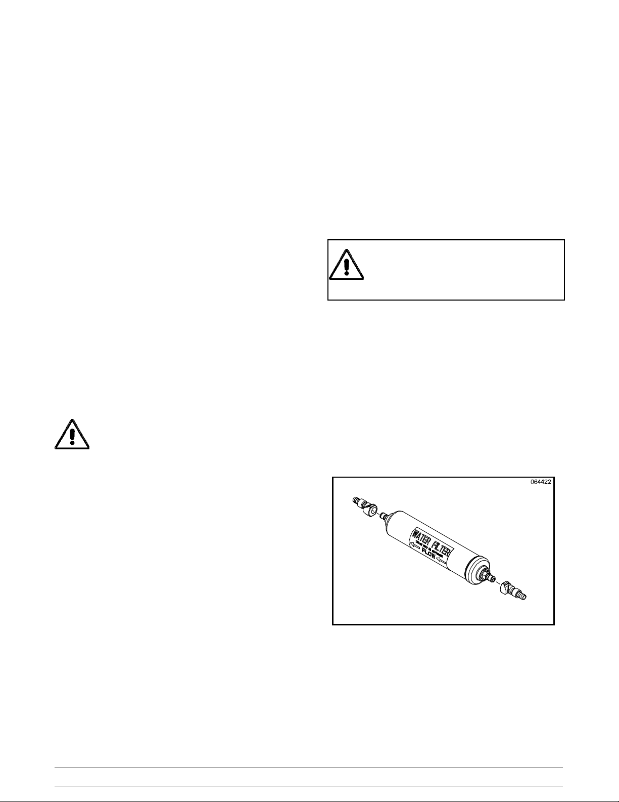
IMPORTANT: The water filter (064422- SER) must
be thoroughly flushed with water before connecting it
to the machine. This removes any loose particles
present from the manufacture of the filter that could
clog the flow control. To flush the filter, connect the
inlet end of the filter to the water supply. Position the
outlet end of the filter over an empty pail. Open the
water supply. Allow water to flow through the filter
until the water exiting the filter is clear. Close the
water supply. Attach the outlet end of the filter to the
machine. Reopen the water supply.
Figure 1
2
Model C300To the Installer
Page 7
Electrical Connections
In the United States, this equipment is intended to
be installed in accordance with the National
Electrical Code (NEC), ANSI/NFPA 70- 1987. The
purpose of the NEC code is the practical
safeguarding of persons and property from hazards
arising from the use of electricity. This code contains
provisions considered necessary for safety.
Compliance therewith and proper maintenance will
result in an installation essentially free from hazard!
In all other areas of the world, equipment should be
installed in accordance with the existing local codes.
Please contact your local authorities.
FOLLOW YOUR LOCAL ELECTRICAL CODES!
Each unit requires one power supply for each data
label on the unit. Check the data label(s) on the
freezer for branch circuit overcurrent protection or
fuse, circuit ampacity, and other electrical
specifications. Refer to the wiring diagram provided
inside of the control box for proper power
connections.
Stationary appliances which are not equipped
with a power cord and a plug or another device to
disconnect the appliance from the power source must
have an all-pole disconnecting device with a contact
gap of at least 3 mm installed in the external
installation.
Appliances that are permanently connected to
fixed wiring and for which leakage currents may
exceed 10 mA, particularly when disconnected or not
used for long periods, or during initial installation, shall
have protective devices such as a GFI, to protect
against the leakage of current, installed by the
authorized personnel to the local codes.
Supply cords used with this unit shall be
oil-resistant, sheathed flexible cable not lighter than
ordinary polychloroprene or other equivalent synthetic
elastomer-sheathed cord (Code designation 60245
IEC 57) installed with the proper cord anchorage to
relieve conductors from strain, including twisting, at
the terminals and protect the insulation of the
conductors from abrasion.
CAUTION: THIS EQUIPMENT MUST BE
PROPERLY GROUNDED! FAILURE TO DO SO
CAN RESULT IN SEVERE PERSONAL INJURY
FROM ELECTRICAL SHOCK!
DO NOT operate this freezer with larger fuses
than specified on the unit data label. Failure to follow
this instruction may result in electrocution or damage
to the machine.
This unit is provided with an equipotential
grounding lug that is to be properly attached to the rear
of the frame by the authorized installer. The installation
location is marked by the equipotential bonding
symbol (5021 of IEC 60417-1) on both the removable
panel and the equipments frame.
If the supply cord is damaged, it must be replaced
by an authorized Taylor service technician in order to
avoid a hazard.
Beater Rotation
Beater rotation must be clockwise as viewed
looking into the freezing cylinder.
Note: The following procedures should be
performed by a trained service technician.
To correct the rotation on a three- phase unit,
interchange any two incoming power supply lines at
freezer main terminal block only.
To correct rotation on a single- phase unit, change
the leads inside the beater motor . (Follow the
diagram printed on the motor.)
131210
Model C300 To the Installer
3
Page 8
Initial Freezing Cylinder Cleaning
Due to the types of products used in FCB
equipment, it is imperative that the freezing cylinder
and the inlet tube be thoroughly brush cleaned,
rinsed, and sanitized before running any product.
Prepare a cleaning solution, using 2 oz. of liquid
detergent in 2 gallons of warm water. Using this
solution, brush clean the freezing cylinder and the
inlet tube. Rinse the freezing cylinder and the inlet
tube with clean water and then sanitize, using the
sanitizing procedures outlined in this Operator
Manual, starting on page 23.
Refrigerant
In consideration of our environment, Taylor
proudly uses only earth friendly HFC refrigerants.
The HFC refrigerant used in this unit is R404A. This
refrigerant is generally considered non-toxic and
non-flammable, with an Ozone Depleting Potential
(ODP) of zero (0).
However, any gas under pressure is potentially
hazardous and must be handled with caution.
NEVER fill any refrigerant cylinder completely with
liquid. Filling the cylinder to approximately 80% will
allow for normal expansion.
Use only R404A refrigerant that conforms
to the AHRI standard 700 specification. The use of
any other refrigerant may expose users and
operators to unexpected safety hazards.
Refrigerant liquid sprayed onto the skin may
cause serious damage to tissue. Keep eyes and skin
protected. If refrigerant burns should occur, flush
immediately with cold water. If burns are severe,
apply ice packs and contact a physician
immediately.
Taylor reminds technicians to be aware of
and in compliance with local government laws
regarding refrigerant recovery , recycling, and
reclaiming systems. For information regarding
applicable local laws, please contact your local
Taylor distributor.
WARNING: R404A refrigerants used in
conjunction with polyolester oils are extremely
moisture absorbent. When opening a refrigeration
system, the maximum time the system is open must
not exceed 15 minutes. Cap all open tubing to
prevent humid air or water from being absorbed by
the oil.
090219
4
Model C300To the Installer
Page 9

Section 2 To the Operator
The freezer you have purchased has been carefully
engineered and manufactured to give you
dependable operation.
The Model C300, when properly operated and cared
for, will produce a consistent quality product. Like all
mechanical products, this machine will require
cleaning and scheduled maintenance. A minimum
amount of care and attention is necessary if the
operating procedures outlined in this manual are
followed closely.
This Operator’s Manual should be read before
operating or performing any maintenance on your
equipment.
Your freezer will NOT eventually compensate and
correct for any errors during the set- up or filling
operations. Thus, the initial assembly and priming
procedures are of extreme importance. It is strongly
recommended that all personnel responsible for the
equipment’s operation study these procedures
together in order to be properly trained and to make
sure that no misunderstandings exist.
In the event you should require technical assistance,
please contact your local authorized Taylor
Distributor for service.
Note: Your Taylor warranty is valid only if the parts
are authorized Taylor parts, purchased from the local
authorized Taylor Distributor, and only if all required
service work is provided by an authorized Taylor
service technician. Taylor reserves the right to deny
warranty claims on units or parts if non- Taylor
approved parts or incorrect refrigerant were installed
in the unit, system modifications were performed
beyond factory recommendations, or it is determined
that the failure was caused by abuse, misuse,
neglect, or failure to follow all operating instructions.
For full details of your Taylor Warranty , please see
the Limited Warranty section in this manual.
Note: Constant research results in steady
improvements; therefore, information in this
manual is subject to change without notice.
If the crossed out wheeled bin symbol is
affixed to this product, it signifies that this product is
compliant with the EU Directive as well as other
similar legislation in effect after August 13, 2005.
Therefore, it must be collected separately after its
use is completed, and cannot be disposed as
unsorted municipal waste.
The user is responsible for returning the product to
the appropriate collection facility, as specified by
your local code.
For additional information regarding applicable local
laws, please contact the municipal facility and/or
local distributor.
Compressor Warranty Disclaimer
The refrigeration compressor(s) on this unit are
warranted for the term stated in the Limited
Warranty section in this manual. However, due to
the Montreal Protocol and the U.S. Clean Air Act
Amendments of 1990, many new refrigerants are
being tested and developed, thus seeking their way
into the service industry. Some of these new
refrigerants are being advertised as drop- in
replacements for numerous applications. It should
be noted that in the event of ordinary service to this
unit’s refrigeration system, only the refrigerant
specified on the affixed data label should be
used. The unauthorized use of alternate refrigerants
will void your Taylor compressor warranty. It is the
unit owner’s responsibility to make this fact known to
any technician he employs.
It should also be noted that Taylor does not warrant
the refrigerant used in its equipment. For example, if
the refrigerant is lost during the course of ordinary
service to this machine, Taylor has no obligation to
either supply or provide its replacement either at
billable or unbillable terms. Taylor does have the
obligation to recommend a suitable replacement if
the original refrigerant is banned, obsoleted, or no
longer available during the five year warranty of the
compressor.
Taylor will continue to monitor the industry and test
new alternates as they are being developed. Should
a new alternate prove, through our testing, that it
would be accepted as a drop- in replacement, then
the above disclaimer would become null and void. To
find out the current status of an alternate refrigerant
as it relates to your compressor warranty, call the
local T aylor Distributor or the Taylor Factory. Be
prepared to provide the Model/Serial Number of the
unit in question.
131210
Model C300 To the Operator
5
Page 10
Section 3 Safety
We at Taylor are concerned about the safety of the
operator when he or she comes in contact with the
freezer and its parts. Taylor has gone to extreme
efforts to design and manufacture built- in safety
features to protect both you and the service
technician. As an example, warning labels have
been attached to the freezer to further point out
safety precautions to the operator.
IMPORTANT - Failure to adhere to the
following safety precautions may result in
severe personal injury or death. Failure to
comply with these warnings may damage the
machine and its components. Component
damage will result in part replacement expense
and service repair expense.
DO NOT operate the freezer without reading
this Operator Manual. Failure to follow this instruction
may result in equipment damage, poor freezer
performance, health hazards, or personal injury.
This unit is to be used only by trained
personnel. It is not intended for use by children or
people with reduced physical, sensory, or mental
capabilities, or lack of experience and knowledge.
Where limited equipment operation is allowed for
public use, such as a self- serve application,
supervision or instruction concerning the use of the
appliance by a person responsible for their safety is
required. Children should be supervised to ensure
that they do not play with the appliance.
This unit is provided with an equipotential
grounding lug that is to be properly attached to the rear
of the frame by the authorized installer. The installation
location is marked by the equipotential bonding
symbol (5021 of IEC 60417-1) on both the removable
panel and the equipments frame.
S DO NOT operate the freezer unless it is
properly grounded.
S DO NOT operate the freezer with larger
fuses than specified on the freezer data
label.
S All repairs must be performed by an
authorized Taylor service technician. The
main power supplies to the machine must
be disconnected prior to performing any
repairs.
S Cord Connected Units: Only Taylor
authorized service technicians may install a
plug on this unit.
S Stationary appliances which are not
equipped with a power cord and a plug or
another device to disconnect the appliance
from the power source must have an all-pole
disconnecting device with a contact gap of
at least 3 mm installed in the external
installation.
S Appliances that are permanently connected
to fixed wiring and for which leakage
currents may exceed 10 mA, particularly
when disconnected or not used for long
periods, or during initial installation, shall
have protective devices such as a GFI, to
protect against the leakage of current,
installed by the authorized personnel to the
local codes.
S Supply cords used with this unit shall be
oil-resistant, sheathed flexible cable not
lighter than ordinary polychloroprene or
other equivalent synthetic
elastomer-sheathed cord (Code designation
60245 IEC 57) installed with the proper cord
anchorage to relieve conductors from strain,
including twisting, at the terminals and
protect the insulation of the conductors from
abrasion.
If the supply cord is damaged, it must be
replaced by an authorized Taylor service
technician in order to avoid a hazard.
DO NOT use a water jet to clean or rinse the
freezer. Failure to follow these instructions may result
in serious electrical shock.
131210
Failure to follow these instructions may result in
electrocution. Contact your local authorized Taylor
Distributor for service.
6
Model C300Safety
Page 11
S DO NOT allow untrained personnel to
operate this machine.
S DO NOT operate the freezer unless all
service panels and access doors are
restrained with screws.
S DO NOT remove any internal operating
parts (example: freezer door, beater,
scraper blades, etc.) unless all control
switches are in the OFF position.
Failure to follow these instructions may result in
contaminated product or severe personal injury to
fingers or hands from hazardous moving parts.
This unit has many sharp edges that can
cause severe injuries.
S DO NOT put objects or fingers in the door
spout. This may contaminate the product
and cause severe personal injury from blade
contact.
S USE EXTREME CAUTION when removing
the beater asssembly. The scraper blades
are very sharp.
This freezer must be placed on a level
surface. Failure to comply may result in personal injury
or equipment damage.
Access to the service area of the unit must
be restricted to persons having knowledge and
practical experience with the unit, in particular as far
as safety and hygiene are concerned.
Cleaning and sanitizing schedules are
governed by your state or local regulatory agencies
and must be followed accordingly. Please refer to the
cleaning section of this manual for the proper
procedure to clean this unit.
CAUTION: This unit is pressurized when
in operation. The control switch must be in the OFF
position until the unit is completely assembled. No
part should ever be removed from the machine while
it is in operation. No part should be removed until
the control switch has been turned to the OFF
position and all pressure has been relieved by
opening the draw valve.
Failure to follow these instructions may result in
severe personal injury from hazardous moving parts
or from the impact of propelled parts.
This unit is designed to maintain product
temperature under 41_F(5_C). Any product being
added to this unit must be below 41_F(5_C). Failure
to follow this instruction may result in health hazards
and poor freezer performance.
DO NOT obstruct air intake and discharge openings:
Air cooled units require a minimum of 3” (76 mm) of
air space on one side, 3” (76 mm) at the rear, and
12” (305 mm) on the top of the unit. This is required
to allow for adequate air flow through the condenser(s). Failure to follow this instruction may
cause poor freezer performance and damage to the
machine.
For Indoor Use Only: This unit is designed to operate
indoors, under normal ambient temperatures of
70_-75_F(21_-24_C). The freezer has successfully
performed in high ambient temperatures of
104_(40_C) at reduced capacities.
DO NOT run the unit without product. Failure to
follow this instruction can result in damage to the
unit.
NOISE LEVEL: Airborne noise emission does not
exceed 78 dB(A) when measured at a distance of
1.0 meter from the surface of the machine and at a
height of 1.6 meters from the floor.
131210
Model C300 Safety
7
Page 12
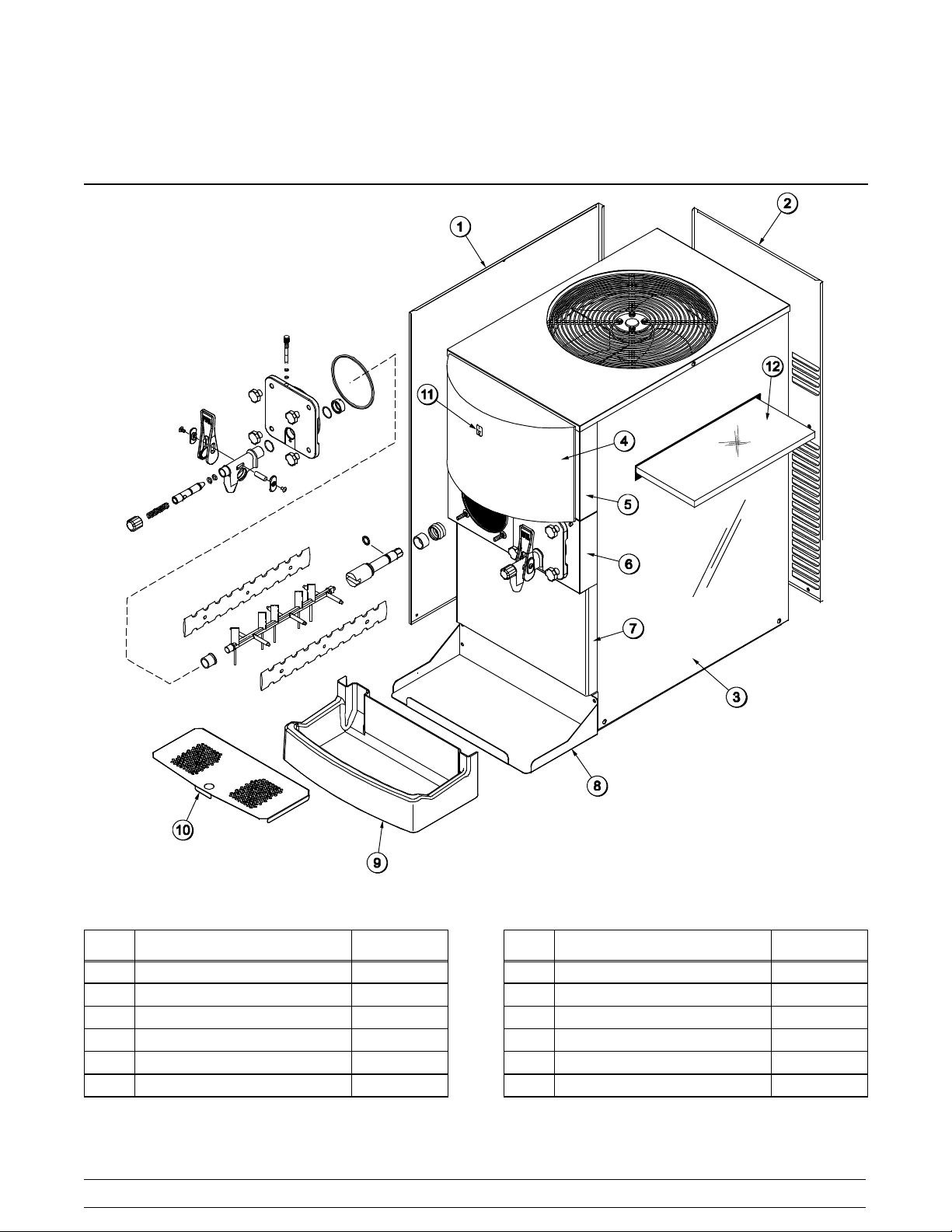
Section 4 Operator Parts Identification
ITEM DESCRIPTION PART NO.
1 PANEL A.-SIDE-LEFT C300 X54676-SER
2 PANEL-REAR 054672
3 PANEL-SIDE-RIGHT 054671
4 DISPLAY-LIGHTED 054683-27
5 PANEL-FRONT-UPPER 054669
6 PANEL-FRONT-SHELL 054668
090417
Figure 2
8
ITEM DESCRIPTION PART NO.
7 PANEL-FRONT-LOWER 054670
8 SHELF-DRIP TRAY 057938
9 TRAY-DRIP 057738
10 SHIELD-SPLASH 057939
11 SWITCH-ROCKER-OFF-ON 078418
12 FILTER-AIR15.88L X 15.88H 052779-5
Model C300Operator Parts Identification
Page 13
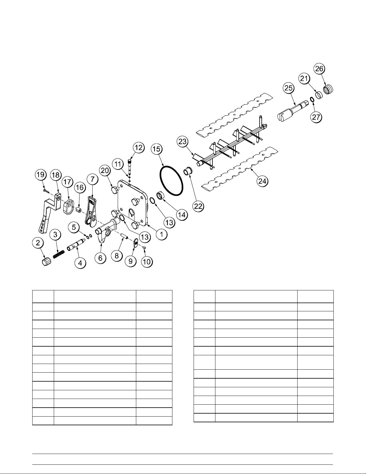
Beater Door Assembly
ITEM
1 DOOR A.- FREEZER- SLUSH X80599
2 CAP- SPOUT- DOOR- FCB 046191- BLA
3 SPRING- COMP.480X.072X3.0 039320
4 VALVE- DRAW- DOOR- SLUSH 039324
*5 O- RING- 9/16 OD X .103W 016369
6 SPOUT-DOOR-FCB-BLACK 046190- BLA
7 HANDLE- DRAW- FCB- BLACK 046192- BLA
8 PIN - PIVOT- SPOUT- DOOR 039321
9 SLIDE - HANDLE- DOOR- FCB 046193- BLA
10 SCREW- 10- 32X3/8 PHIL 053869
*11 O- RING- 9/32 OD X 1/16 WALL 029751
12 PLUG - PRIME- SLUSH 039568
*13 O- RING- 1.129 ODX.989ID 039219
14 NUT - SPOUT- DOOR- SLUSH 039323
DESCRIPTION PART NO.
Figure 3
ITEM DESCRIPTION PART NO.
*15 O- RING- 5- 1/4O.D. X .210W 017003
16 PIN- HANDLE- ADA- FCB 068601
17 ADAPTOR- MOUNTING- ADA 068579
18 HANDLE - ADA- FCB 068580
19 SCREW- 10/32X1” PHIL 069069
20 NUT - STUD 043666
21 BUSHING- BEATER
SHAFT/BOOT SEAL
22 BEARING- FRONT- SLUSH 039349
23 BEATER- PLASTIC- FCB 041182
24 BLADE - SCRAPER- FCB 16L 041103
25 SHAFT - BEATER- SLUSH 039337
26 SEAL - DRIVE SHAFT 032560
27 O- RING- 7 /8 OD X .139W 025307
*O- RINGS COME 25 TO A BAG
042278
140509
Model C300 Operator Parts Identification
9
Page 14
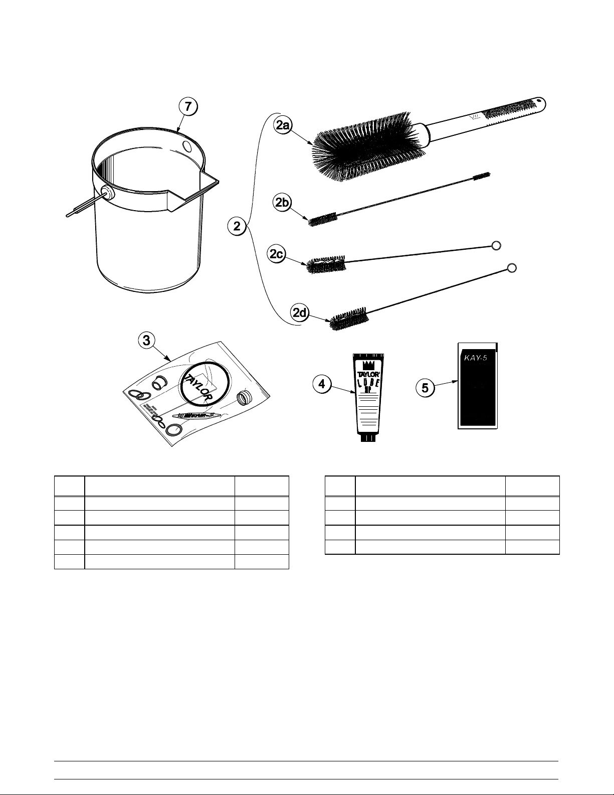
Accessories
ITEM DESCRIPTION PART NO.
1 PAIL-10QT 013163
2 BRUSH A.-PACKAGE X64275
2a BRUSH-MIX PUMP BODY-3”X7” 023316
2b BRUSH-DOUBLE ENDED 013072
2c BRUSH-REARBRG 1”DX2“L 013071
Figure 4
ITEM DESCRIPTION PART NO.
2d BRUSH-DRAW VALVE 1-1/2”OD 014753
3 KIT A.-TUNE UP X39699
4 LUBRICANT-TAYLORHI PERF 048232
5 SANITIZERKAY-5 125 PACKETS 041082
140804
10
Model C300Operator Parts Identification
Page 15
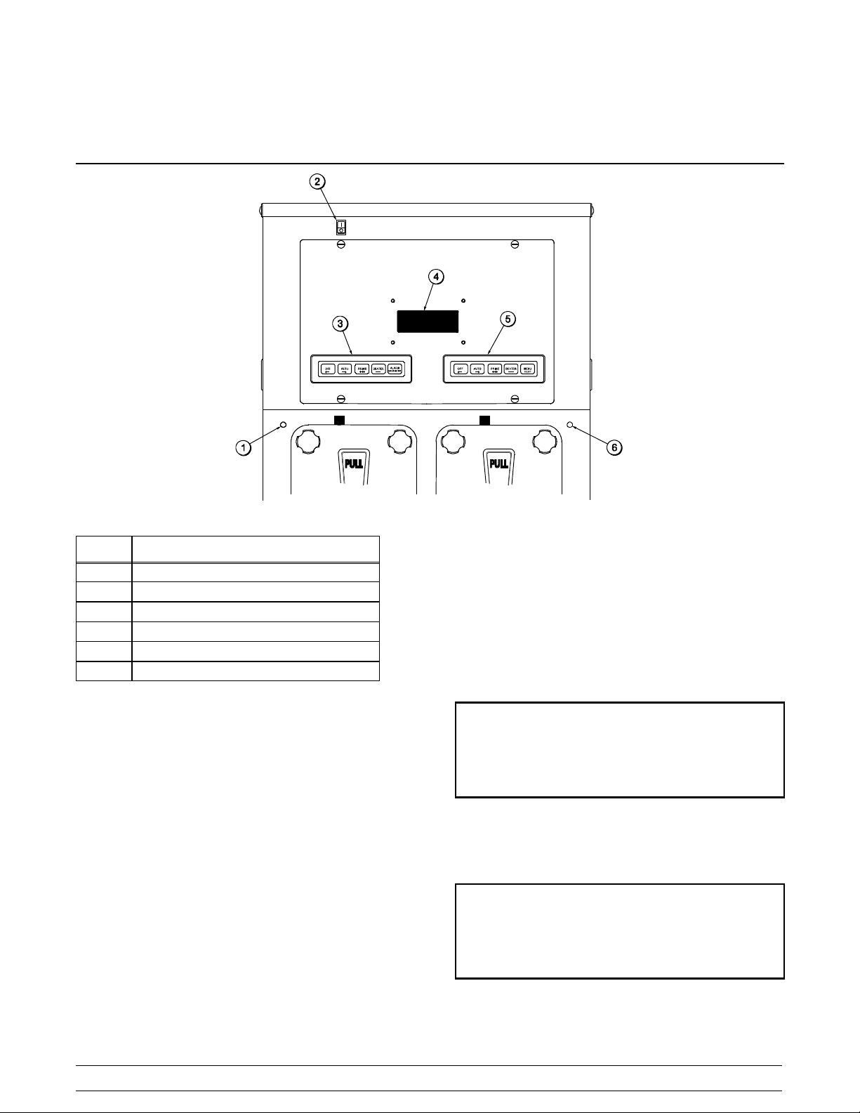
Section 5 Important: To the Operator
Figure 5
ITEM
1 Product Light - Left Side
2 Control Switch
3 Keypad - Left Side
4 Liquid Crystal Display
5 Keypad - Right Side
6 Product Light - Right Side
DESCRIPTION
Control Switch
The control switch is located at the top left corner of
the control channel. When placed in the ON position,
allows SLUSHTECH operation.
Liquid Crystal Display
The Liquid Crystal Display (LCD) is located on the
front control panel. The LCD is used to show the
current operating mode of the freezing cylinders.
The LCD also indicates whether there is enough
syrup, CO2, and water being supplied to the freezer.
If an error in the machine operation occurs, a
warning tone will sound and the word “FAULT” will
flash on the third line of the display.
Operational Mode Display
The displays below illustrate the Operational Mode
Displays. This information appears on the LCD
during normal operation.
When the unit is plugged into the wall receptacle
and the control switch is in the ON position, this
screen appears.
SAFETY TIMEOUT
ANY KEY ABORT
This display will remain on the LCD for 60 seconds
unless a key is pressed. When any key is pressed
(or 60 seconds passes), the next screen appears.
OFF MODE OFF
OK SYRUP OK
CO2- OK WATER- OK
Note: Syrup, CO2and water are satisfied.
Model C300 Important: To the Operator
11
Page 16

Pressing the AUTO (- - >) keys on both sides of the
unit will display this screen.
AUTO MODE AUTO
OK SYRUP OK
CO2- OK WATER- OK
Operator Menu Timeout
If the display is left in the operator menu or any of
the operator menu selections, except for Current
Conditions, the display will return to the system
mode screen 60 seconds after the last keypress.
The Current Conditions screen will be displayed until
manually changed.
Finding Current Fault Conditions
Line 1 indicates the operating mode for each
freezing cylinder.
Line 2 indicates the status of the syrup systems in
each freezing cylinder. As long as syrup is available,
the word “OK” will appear on the LCD. When the
syrup supply is insufficient, the word “OUT” will flash
on the LCD. The same rules apply to the fourth line
which indicates the status of the CO
and the water.
2
The third line of this display is a fault indicator. If an
error in machine operation occurs, the word “FAULT”
will be displayed on the LCD.
BEATER MODE BEATER
OUT SYRUP OUT
- - FAULT- - - - FAULT- -
CO2- OUT WATER- OUT
Operator Menu Display
The OPERATOR MENU is used to enter into the
operating screens. T o access the OPERAT OR
MENU, simply press the MENU (SEL) key. The
cursor will flash under the letter “A”, indicating that
this is screen A. To select a different screen, use the
AUTO (- - >) and OFF (<- - ) keys to move the
cursor to the desired screen selection and press the
MENU (SEL) key.
Screen B is FAULT DESCRIPTION. The fault
description will indicate if there is a fault in one of the
freezing cylinders. When the actual fault is
corrected, the warning tone will stop. Only item 9
requires pressing the OFF (<- - ) key to clear the
fault message and the warning tone.
Fault Messages
No Fault Found No fault conditions are
apparent.
Beater Overload Beater is out on overload.
Chk Refrig Sys Psi Out on compressor high
pressure cut- out.
Thermistor Short Shorted thermistor probe.
Thermistor Open Open thermistor probe.
Syrup Pressure Low Syrup is no longer present.
CO2 Pressure Low CO2pressure is low.
H2O Pressure Low Water pressure is low.
BRL Not Cooling Freezing cylinder is not
cooling after 5 minutes.
BRLTemp2High Freezing cylinder
temperature is above 120_F
(49_C).
The following are explanations of the possible faults
and the display screens. Lines 2 and 3 indicate the
faults found in freezing cylinders 1 and 2
respectively.
1. NO FAULT FOUND - No fault conditions are
apparent.
OPERATOR MENU
BCDEFGHI
A
EXIT MENU
<- - - - > SEL
12
FAULT DESCRIPTION
L: NO FAULT FOUND
R: NO FAULT FOUND
CLR +++ SEL
Model C300Important: To the Operator
Page 17

2. BEATER OVERLOAD - Beater motor is out on
overload. When this fault occurs, the machine
automatically turns off. The fault clears when
the condition is corrected.
FAULT DESCRIPTION
L: BEATER OVERLOAD
R: BEATER OVERLOAD
CLR +++ SEL
3. CHK REFRIG SYS PSI - Compressor is out on
high head pressure. When this fault occurs, the
machine automatically turns off. The fault clears
when the condition is corrected.
FAULT DESCRIPTION
L: CHK REFRIG SYS PSI
R: CHK REFRIG SYS PSI
CLR +++ SEL
4. THERMISTOR SHORT - One or both of the
barrel (freezing cylinder) thermistor probes are
faulty.
FAULT DESCRIPTION
L: THERMISTOR SHORT
R: NO FAULT FOUND
CLR +++ SEL
5. THERMISTOR OPEN - One or both of the
barrel (freezing cylinder) thermistor probes are
faulty.
6. SYRUP PRESS LOW - When the syrup out
indicator displays a lack of syrup, the unit will
enter a HOLD mode. At this time, no
refrigeration or product flow from the flow
control will be allowed. Only the beater will
operate. When the syrup is satisfied the unit will
refill the product tank, and then automatically
return to the AUTO mode. The fault message
and the warning tone will clear.
FAULT DESCRIPTION
L: NO FAULT FOUND
R: SYRUP PRESS LOW
CLR +++ SEL
7. CO2PRESSURE LOW - When the CO2out
indicator displays a lack of CO
internal timer will start. If the CO
, a 60 second
2
is not
2
replenished at the end of the 60 seconds, both
freezing cylinders will shut down and this fault
message will appear. Replenish the CO
2
and
the fault message and warning tone will clear.
FAULT DESCRIPTION
L: CO2 PRESSURE LOW
R: CO2 PRESSURE LOW
CLR +++ SEL
8. H2O PRESSURE LOW - When the water out
indicator displays a lack of water, a 60 second
internal timer will start. If the water is not
replenished at the end of the 60 seconds, both
freezing cylinders will shut down and this fault
message will appear. Replenish the water and
the fault message and warning tone will clear.
FAULT DESCRIPTION
L: THERMISTOR OPEN
R: NO FAULT FOUND
CLR +++ SEL
Model C300 Important: To the Operator
13
FAULT DESCRIPTION
L: H2O PRESSURE LOW
R: H2O PRESSURE LOW
CLR +++ SEL
Page 18

9. BRL NOT COOLING - A freezing cylinder
check has been established for the AUTO
mode of operation. If a freezing cylinder enters
the AUTO mode, the control will check product
temperature. After five minutes, it will again
check product temperature. If product
temperature does not drop in that five minute
time span, the freezing cylinder will shut down
and this message will appear on the fault
screen. For this check to be valid, the product
temperature must be above 40_F(4.4_C).
FAULT DESCRIPTION
L: BARREL NOT COOLING
R: NO FAULT FOUND
CLR +++ SEL
Screen C is SET CLOCK.UsetheAUTO(- ->)
and OFF (<- - ) keys to place the cursor under the
element to be set (hours, minutes, month, day, or
year). Use the PRIME (+++) and BEATER (- - - )
keys to increment or decrement the value. Press the
MENU (SEL) key to advance to the Daylight Saving
Time screen.
Note: The clock is programmed with military time.
SET CLOCK
:30 6/25/01
14
<- - - -> +++ - - - SEL
This screen will appear if an invalid date is entered.
(example: If the date entered exceeds the days of
that month.)
10. BRL TEMP 2 HIGH - A maximum allowable
product temperature has been established to
prevent product from excessive heating. If the
product exceeds 120_F(49_C) temperature for
any reason (in any mode of operation), the
entire unit shuts down.
FAULT DESCRIPTION
L: BARREL TEMP 2 HIGH
R: NO FAULT FOUND
CLR +++ SEL
Faults, when corrected, are cleared from the fault
description screen, with the following exception:
BRL NOT COOLING. This fault requires the
operator to press the OFF (<- - ) key (when in the
FAULT DESCRIPTION screen) in order for the fault
to discontinue.
To see if there is more than one fault in either
freezing cylinder, press the PRIME (+ + +) key. To
return to the OPERATOR MENU, press the MENU
(SEL) key once. To return to the Main Screen, use
the AUTO (- - >) key to cycle to MENU ITEM A,
then press the MENU (SEL) key.
SET CLOCK
:30 02/31/01
14
INVALID DA TE
SEL
This screen allows the Daylight Saving Time options.
If the Daylight Saving Time option is enabled, then
the time will be advanced by one hour at 2:00 a.m.
on the first Sunday in April, and will be retarded by
one hour at 2:00 a.m. on the last Sunday in October.
DAYLIGHT SAVING TIME
ENABLE
<- - - - > SEL
DISABLE
Screen D is MANUAL DEFROST. This screen
allows the operator to manually defrost the left side
of the unit.
Place the cursor under YES, press the MENU (SEL)
key, and the command will be executed.
MANUAL DEFROST
LEFT SIDE YES
<- - - - > SEL
NO
14
Model C300Important: To the Operator
Page 19

Repeat the procedure for the right side of the unit.
The fourth feature will display the Power Saver
Mode, OFF, REST, or STANDBY status.
MANUAL DEFROST
RIGHT SIDE YES
<- - - - > SEL
NO
Note: Only one side of the unit may be placed in
the DEFROST mode at a given time. Attempting to
place a side of the unit into DEFROST while the
other side is defrosting, will result in the following
screen:
ALREADY IN DEFROST
Press the MENU (SEL) key to return the unit to the
OPERATOR MENU.
Screen E is SYSTEM INFORMATION. It consists of
6 display features.
The first feature indicates the software version.
If the Power Saver Mode is OFF, the following
screen will be displayed.
POWER SAVER MODE
OFF
SEL
If a Power Saver Mode is programmed, one of the
following screens will appear.
POWER SAVER REST
CYCLE 1
POWER SAVER STANDBY
CYCLE 1
SUN 01:00
SUN 08:30
+++ - - - SEL
SUN 01:00
SUN 08:30
+++ - - - SEL
SYSTEM INFORMATION
C300 CONTROL UVC2
VERSION 1.03
SEL
The second feature indicates the bill of material
number and the serial number. It also indicates if the
unit is equipped with a water pressure switch.
B.O.M. C30027C000
S/N K0000000
WITH H20 PRESS SW
SEL
The third feature indicates the version number of the
language and text.
SYSTEM INFORMATION
LANGUAGE
VERSION 1.09 ENGLISH 446
SEL
The fifth feature will indicate the left side defrost time
and which day(s) the defrost will occur.
DEFROST TIME LEFT
CYCLE 1
DEFROST TIME LEFT
CYCLE 1
<- - - -> +++ - - - SEL
ALL 09:00
+++ - - - SEL
SUN 09:00
The sixth feature will indicate the right side defrost
time and which day(s) the defrost will occur.
DEFROST TIME RIGHT
CYCLE 1
ALL 10:00
+++ - - - SEL
Model C300 Important: To the Operator
15
Page 20

DEFROST TIME RIGHT
CYCLE 1
SUN 10:00
Press the AUTO (- - >) key to move to the next
screen. The next screen will indicate when the fault
was satisfied.
<- - - -> +++ - - - SEL
Press the MENU (SEL) key to return to the
OPERATOR MENU.
Screen F is CURRENT CONDITIONS. This screen
displays the current viscosity, product temperature,
and pressure for each freezing cylinder. An asterisk
will indicate which side is refrigerating. Press the
MENU (SEL) key to return to the OPERATOR
MENU.
Note: Viscosity is checked only when product
temperature is below 40
CURRENT CONDITIONS
L*1200Hd 27.3F
R*2140Hd 27.3F
_F/4.4_C.
SEL
Screen G is FAULT HISTORY. This option provides
a record of the last 20 faults. The display also
indicates the date and time each fault occurs.
FAULT HISTORY 2
06/25/01 14:06:19
RESTORED FROM FAULT
PAGE2 +++ - - - SEL
Press the MENU (SEL) key to return to the
OPERATOR MENU.
Screen H is RINSE/SANITIZE. This screen allows
the operator to rinse or sanitize the freezing
cylinder(s).
RINSE / SANITIZE
RINSE SANITIZE EXIT
---
<- - - - > SEL
Use the AUTO (- - >) and OFF (<- - ) keys to select
either RINSE or SANITIZE, and then press the
MENU (SEL) key.
SANITIZE
LEFT SIDE YES NO
---
<- - - - > SEL
FAULT HISTORY 1
06/25/01 08:34
NO FAULT FOUND
<- - - -> +++ - - - SEL
Press the AUTO (- - >) and OFF (<- - ) keys to
increase or decrease the fault page.
Page numbers are located in the upper right hand
corner of the display. The most recently recorded
fault will appear on page 1. The fault description is
listed on the third line of the fault page.
FAULT HISTORY 2
06/25/01
R SYRUP PRESS LOW 08:33
<- - - -> +++ - - - SEL
Use the cursor keys to select YES or NO, then
press the MENU (SEL) key.
SANITIZE
RIGHT SIDE YES NO
---
<- - - - > SEL
Repeat for the right side of the unit.
Screen I is SERVICE MENU. This screen allows
the authorized service technician to access service
information. Press the MENU (SEL) key to return to
the OPERATOR MENU.
OPERATOR MENU
ABCDEFGHI
SERVICE MENU
<- - - - > SEL
16
Model C300Important: To the Operator
Page 21

Syrup Out Indicator
AUTO MODE AUTO
OUT SYRUP OK
CO2- OK WATER- OK
supplied to the freezer. In addition, the product light
will illuminate and a warning tone will sound. This
will continue until the proper amount of water is
supplied to the freezer. If the water is not supplied
within one minute, the machine will shut down and a
fault message will appear.
If the word “OUT” appears in one of the columns
next to the word “SYRUP”, it indicates a lack of
syrup or syrup pressure being supplied for the
indicated freezing cylinder. If the unit is in the AUTO
or PRIME modes, the product light will illuminate
and a warning tone will sound for that freezing
cylinder. At this time, replace the appropriate
bag- in- the- box. As a safety feature, the
refrigeration system automatically stops to prevent a
freeze- up in the freezing cylinder.
If a syrup out condition occurs on one side, that side
will enter the HOLD mode at which time refrigeration
remains off, the beater continues to run, and the
solenoid is closed for that side to prevent the
CO
2
dispensing of product. The opposite side will not be
affected.
CO2Out Indicator
AUTO MODE AUTO
OK SYRUP OK
CO2- OUT WATER- OK
Audio Alarm Silencer
The audio alarm will be disabled if the ALARM
SILENCE key is pressed. If a new fault or fault
condition occurs or the system mode changes, the
audio alarm will be re- enabled automatically. If the
audio alarm is silenced for greater than 30 minutes
without correcting the fault, it will be re- enabled
automatically.
Product Light
When the light is continuously lit (not flashing) it
indicates that there is an “OUT” condition for syrup,
water, or CO
When the light is flashing, it indicates that the
product is not at serving viscosity. This will occur
during the initial freeze down, a defrost cycle and a
FAULT condition and during power saver modes.
.
2
On the LCD, if the word “OUT” appears next to the
word “CO2” it indicates a lack of CO2 being supplied
to the freezer. The product light will also illuminate
and a warning tone will sound. This will continue
until the CO2 is replaced. If the CO2 is not replaced
within one minute, the machine will shut down and a
fault message will appear.
Sampling Valve
The sampling valve is located behind the lower front
panel. The sampling valve is used to obtain a brix
reading.
Water Out Indicator
Daily Procedures
AUTO MODE AUTO
OK SYRUP OK
CO2- OK WATER - OUT
On the LCD, if the word “OUT” appears next to the
word “WATER”, it indicates a lack of water being
Model C300 Important: To the Operator
The following procedure should be performed daily.
Remove the splash shield and front drip tray. Take
these parts to the sink and brush- clean them.
Re- install the parts onto the freezer. Use a clean,
sanitized towel and wipe down the front of the
machine, including the doors and spouts.
17
Page 22

Section 6 Operating Procedures
The Model C300 contains two 7 quart (6.6 liter)
freezing cylinders.
CAUTION: This unit is pressurized when
in operation. The control switch must be in the OFF
position until the unit is completely assembled. No
part should ever be removed from the machine while
it is in operation. No parts should be removed until
the control switch has been turned to the OFF
position and all pressure has been relieved by
opening the draw valve. Failure to follow this
instruction may result in severe personal injury from
hazardous moving parts or from the impact of
propelled parts.
The syrup flow control combines the two ingredients
of water and syrup, and sends this combination to
the freezing cylinder. As product is drawn, new
product will flow from the flow control into the
freezing cylinder. CO
control to carbonate the product and aid in
dispensing.
We begin our instructions at the point where the
parts are disassembled and laid out to air dry.
is supplied after the flow
2
Assembly
MAKE SURE THE CONTROL SWITCH IS
IN THE “OFF” POSITION. Failure to do so may
result in personal injury or component damage.
Note: When lubricating parts, use an approved food
grade lubricant (example: Taylor Lube HP).
Step 1
Lubricate the o- ring groove. Slide the o- ring into the
groove on the drive shaft. Lubricate the drive shaft
seal groove, the o- ring, and the shaft portion that
comes in contact with the bearing on the beater
drive shaft. DO NOT lubricate the hex end of the
drive shaft.
The following procedures will show you how to
assemble the parts into the freezer, sanitize them,
and prime the freezer with fresh product.
Duplicate the following procedures, where they
apply, for the other freezing cylinder.
If you are disassembling the machine for the first
time or need information to get to this starting point
in our instructions, turn to page 29 , “Disassembly”
and start there.
Figure 6
090417
18
Model C300Operating Procedures
Page 23

Step 2
Lubricate the inside diameter of the drive shaft seal.
Install the drive shaft seal bushing in the drive shaft
seal.
Figure 7
Step 4
Insert the beater drive shaft into the freezing
cylinder, hex end first, and into the rear shell bearing
until the seal fits securely over the rear shell bearing.
Be certain the drive shaft fits into the drive coupling
without binding. Remove any excess lubricant from
the seal.
Note: The drive shaft bushing must be positioned in
the center of the drive shaft seal.
Step 3
Slide the seal and bushing over the shaft and groove
until it snaps into place. Fill the inside portion of the
seal with more lubricant and evenly lubricate the end
of the seal that fits onto the rear shell bearing.
Figure 8
Figure 9
Step 5
Install the beater assembly. First check the scraper
blades for any nicks or signs of wear. If any nicks
are present or if the blade is worn, replace both
blades. If the blades are in good condition, place the
scraper blades over the holding pins on the beater.
Note: Each hole on the scraper blade must fit
securely over each pin.
Figure 10
090417
Model C300 Operating Procedures
19
Page 24

Step 6
Align the flats on the end of the beater assembly
with the drive shaft. Make sure the beater assembly
locating pin is in position in the locating hole of the
drive shaft. Turn the beater slightly to be certain that
the beater is properly seated. When in position, the
beater will be approximately 3/8” inside the front of
the freezing cylinder.
Important: Failure to properly seat the beater
may cause damage to the beater and the door.
Figure 11
Note: The scraper blades on the beater assembly
should be in the 6 and 12 o’clock positions. This will
enable freezer door installation.
Step 7
Install the draw valve. Slide the two o- rings into the
grooves on the draw valve. Lubricate the o- rings
and the valve as illustrated below.
Figure 13
Step 8
Insert the draw valve into the freezer door spout
from the front of the unit. The valve is properly
installed when the hole in the draw valve is visible in
the slot of the freezer door spout.
Figure 12
20
Figure 14
Model C300Operating Procedures
Page 25

Step 9
Snap the draw valve handle onto the door spout.
Align the hole in the draw valve with the slot in the
draw handle.
Step 12
Insert the spring into the front of the door spout.
Figure 18
Figure 15
Step 10
Slide the pivot pin through the draw handle and into
the draw valve. Place the draw handle slide over the
opening in the draw handle and the pivot pin.
Figure 16
Step 11
Secure the assembly with screws.
Step 13
Place the threaded cap on the end of the draw valve
cavity. Turn the cap clockwise until it is secure.
Figure 19
Step 14
Place the two o- rings on the prime plug and lightly
lubricate.
Figure 17
Model C300 Operating Procedures
21
Figure 20
Page 26
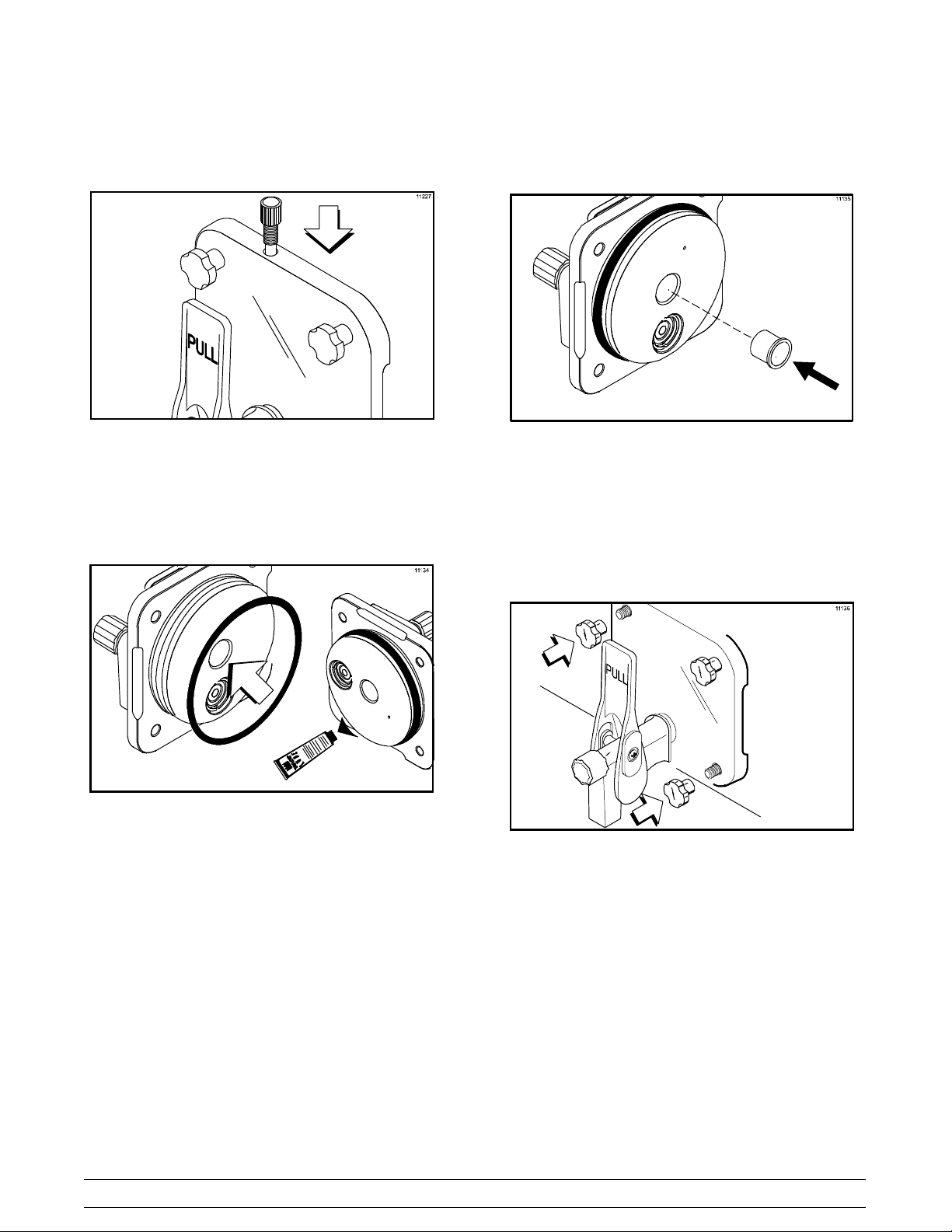
Step 15
Install the prime plug.
Step 17
Install the front bearing. Do not lubricate the front
bearing.
Figure 21
Step 16
Place the large o- ring into the door groove and
lightly lubricate.
Figure 22
Note: Every four months or less, discard the
o- rings and install new o- rings.
Figure 23
Step 18
Install the freezer door. Position the door on the four
studs on the front of the freezing cylinder. Firmly
push the door into place. Install the four handscrews
on the studs and finger- tighten them equally in a
criss- cross pattern to insure that the door is snug.
Do not over- tighten the handscrews.
Figure 24
Repeat these steps for the other freezing cylinder.
090417
22
Model C300Operating Procedures
Page 27
Sanitizing
Note: If a unit is sanitized, and will not be used for
an extended period of time, clean water should be
used to flush all sanitizer from the lines. Remove the
water from all the lines and components prior to
storage of the unit. Upon return to service, the unit
must be sanitized prior to use.
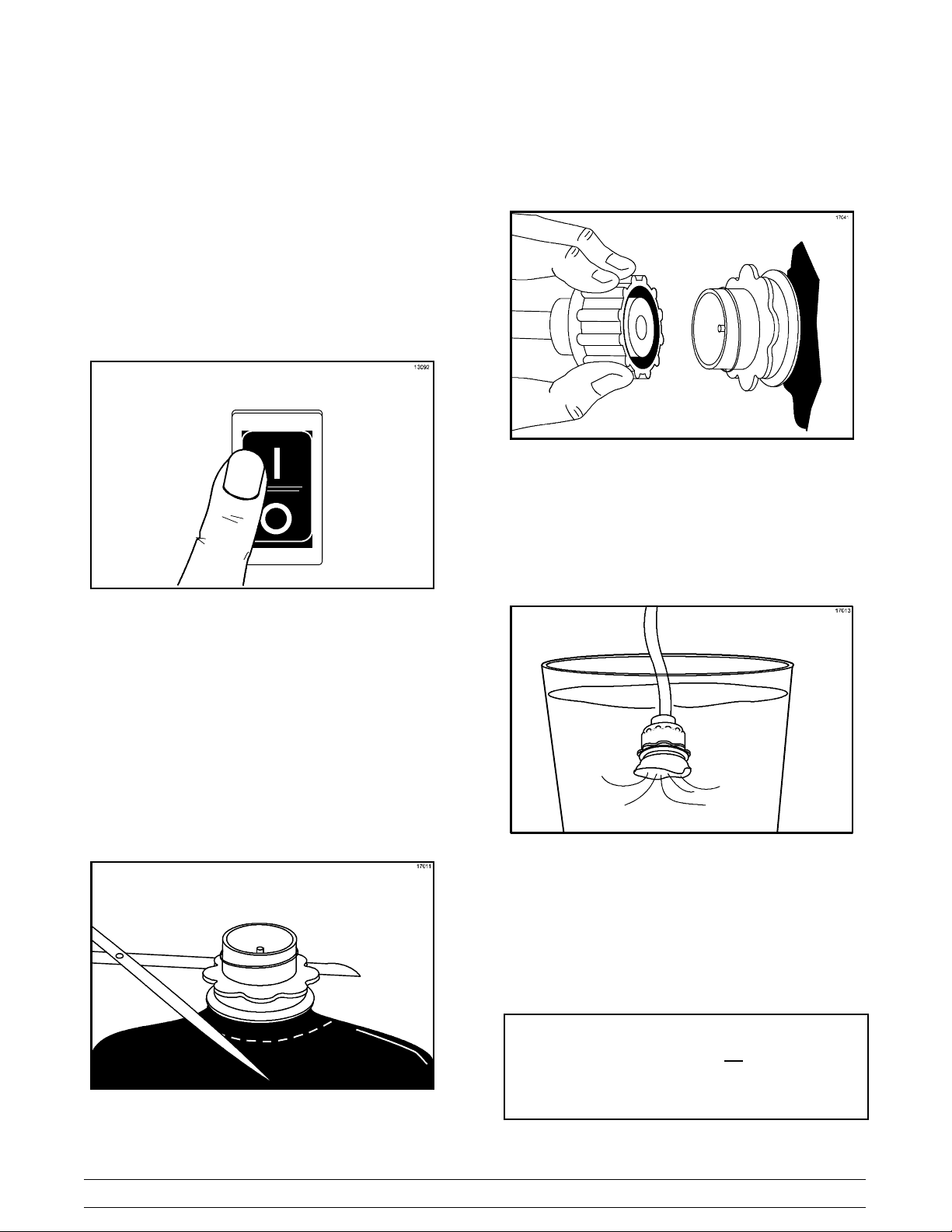
Step 1
Open the lighted display door. Place the control
switch in the ON position.
Step 4
Connect the syrup line to the syrup line connector
that was cut from the syrup bag.
Figure 27
Step 5
With the bag connector attached to the syrup line,
place the syrup line into the pail of sanitizing
solution.
Figure 25
Step 2
Prepare an approved 100 PPM sanitizing solution
(examples: 2- 1/2 gal. [9.5 liters] of Kay- 5R or 2
gal. [7.6 liters] of Stera- SheenR) in a clean, empty
pail. USE WARM WATER AND FOLLOW THE
MANUFACTURER’S SPECIFICATIONS.
Important: Make sure the sanitizer is completely
dissolved.
Step 3
Using an empty bag of syrup, cut the syrup line
connector from the end of the bag.
Figure 26
Figure 28
Step 6
To place the left freezing cylinder in the SANITIZE
mode, press the MENU (SEL) key. Move the cursor
by pressing the AUTO (- - >) key until the third line
indicates RINSE / SANITIZE.
OPERATOR MENU
ABCDEFGH
RINSE / SANITIZE
<- - - - > SEL
I
080507
Model C300 Operating Procedures
23
Page 28

Press the MENU (SEL) key.
Move the cursor under the word “SANITIZE” by
pressing the OFF (<- - )key.
Step 9
Continue filling the freezing cylinders with sanitizing
solution until the solution purges out of the relief
valve at the top of the mix tank, and begins draining
into the front drip tray. Press the OFF (<- - ) key.
RINSE / SANITIZE
RINSE SANITIZE EXIT
-----
<- - - - > SEL
Step 7
Pressing the MENU (SEL) key will give you the
option for sanitizing the left freezing cylinder. Move
the cursor under the word “YES”. Pressing the
MENU (SEL) key at this time will start the flow of
sanitizing solution into the left freezing cylinder.
SANITIZE
LEFT SIDE YES NO
---
<- - - - > SEL
Repeat Steps 6 - 7 for the right side freezing
cylinder.
SANITIZE
RIGHT SIDE YES NO
---
<- - - - > SEL
Step 10
Press the BEATER (- - - ) key. Agitate the solution
in the freezing cylinders for five minutes.
Figure 30
Step 11
With a pail beneath the door spouts, open the draw
valves and drain all the solution from the freezing
cylinders. Press the OFF (<- - ) key and close the
draw valves.
Step 8
Open the prime plugs. When sanitizing solution fills
the freezing cylinders approximately 2/3 full, close
the prime plugs.
Figure 29
Figure 31
Step 12
Disconnect the syrup connectors in the sanitizing
solution.
24
Model C300Operating Procedures
Page 29
Priming/Brixing
Step 1
Connect the syrup line to the Bag- in- Box (BIB)
syrup.
Step 2
Remove the drip tray, splash shield and the lower
front panel to gain access to the syrup sampling
valves.
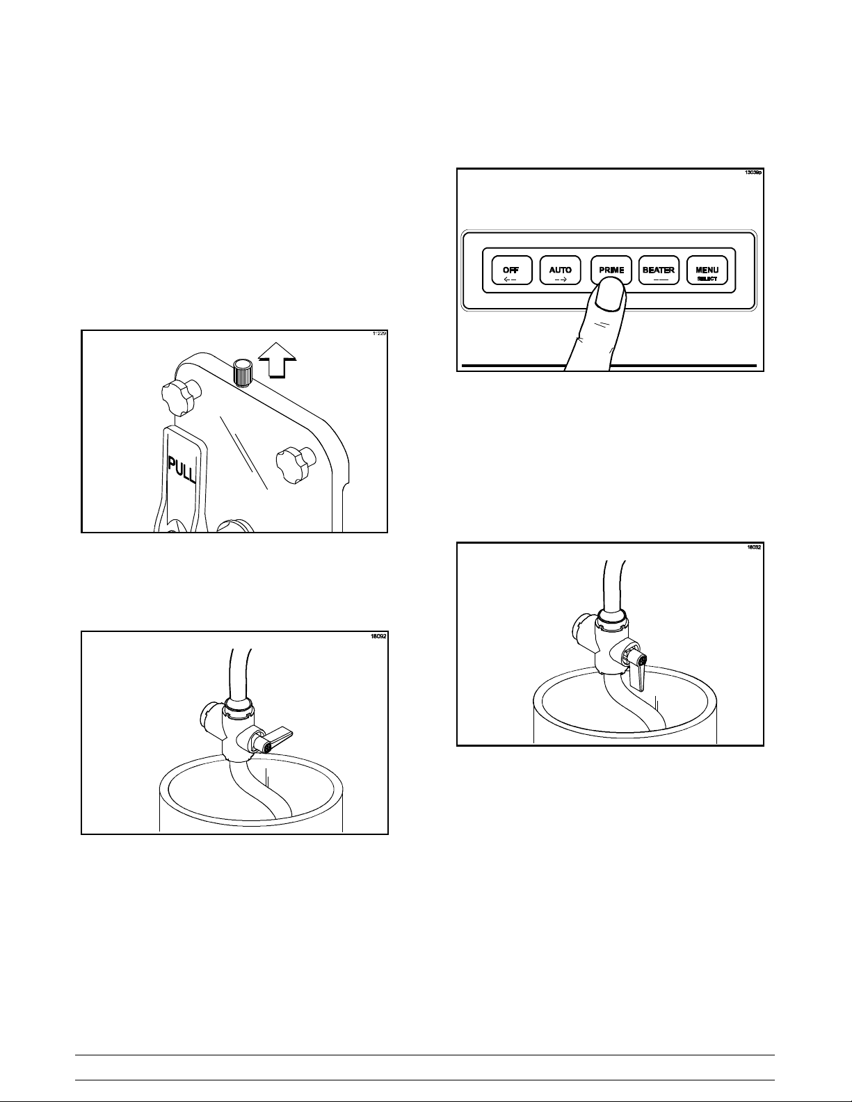
Step 3
Open the prime plug.
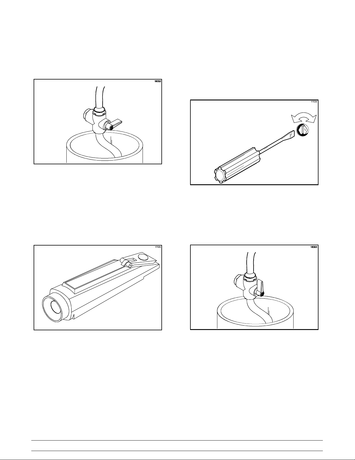
Step 5
Press the PRIME (+ + +) key .
Figure 34
Step 6
Slowly move the syrup sampling valve to the fully
open position by turning the handle “down” toward
the sampling line. Allow the liquid to run into a pail
until all the sanitizer is removed and full strength
product is flowing.
Figure 32
Step 4
Place the sampling valve in the OFF (center)
position.
Figure 33
Figure 35
Brix is the ratio of syrup to water which will directly
affect the quality and taste of the product. Brixing
should be done before priming the freezer and when
a change in syrup flavor has been made.
Model C300 Operating Procedures
25
Page 30
Step 7
Drain the product from the syrup sampling valve into
a cup. Close the syrup sampling valve by turning the
handle to the center position.
Figure 36
Step 8
Stir the finished product. Pour a small amount of
product over the refractometer. The brix reading
should register 13 to 14. A reading higher than this
would cause a darker, richer product. The
refrigeration system would have to run longer to
freeze the excess syrup. A reading lower than this
could cause a freeze- up in the freezing cylinder
because of the excess water.
Step 9
To adjust the brix, turn the adjustment screw located
behind the drip tray shelf. Clockwise adjustments
increase the amount of syrup to water, and
counterclockwise adjustments decrease the amount
of syrup to water. Adjust the screw in small
increments and check the brix again.
Figure 38
Repeat this step until a correct brix reading is
registered.
Step 10
Once the proper brix has been achieved, turn the
handle “up” to allow product to flow to the mix tank.
Figure 37
26
Figure 39
Model C300Operating Procedures
Page 31
Note: The position of the handle on the syrup
sampling valve determines the direction of product
flow. The down position opens the syrup sampling
valve for collecting brix samples. The center position
shuts off the product flow. The up position directs
the flow of product to the freezing cylinder.
Step 11
Place a pail beneath the door spout. Open the draw
valve and drain the freezing cylinder to remove any
incorrectly brixed product. Close the draw valve.
Step 12
Slowly open the prime plug.
Step 13
Press the PRIME (+ + +) key. Allow the liquid level
to fill to the prime plug hole.
Step 14
Press the OFF (<- - ) key and close the prime plug.
Repeat Steps 1 through 14 for the other freezing
cylinder.
Step 16
Close the lighted display when complete. Replace
the panels and attach with screws. Install the front
drip tray and the splash shield on the front of the
freezer.
Figure 41
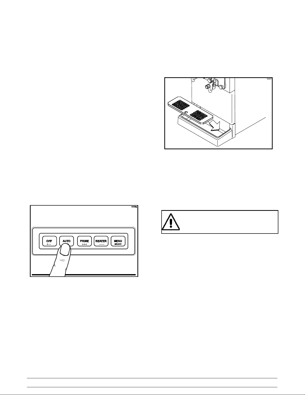
Step 15
To place the freezing cylinders in the AUTO mode,
press the AUTO (- - >) key on both sides. When the
unit cycles off, the product will be at serving
viscosity.
Figure 40
120 Day Closing Procedure
We recommend that the machine be completely
disassembled and cleaned at least every 120 days
using the following procedures.
ALWAYS FOLLOW LOCAL HEALTH CODES
To disassemble the Model C300, the following items
will be needed:
S Two cleaning pails
S Necessary brushes (provided with freezer)
S Cleaner
S Single service towels
Model C300 Operating Procedures
27
Page 32

Draining Product From the
Freezing Cylinder
Step 1
With a pail beneath the door spout, press the
BEATER (- - - ) key. This will allow the beater to
operate and CO
push the product from the freezing cylinder. Open
the draw valve and drain the product from the
machine until the CO
Step 2
When all the product has been drained from the
freezing cylinder, close the draw valve and press the
OFF (<- - ) key. Discard this product.
pressure will be maintained to
2
begins to jet.
2
Figure 42
Rinsing
Step 1
To place the left cylinder in the RINSE mode, press
the MENU (SEL) key. Move the cursor by pressing
the AUTO (- - >) key until the third line indicates
RINSE / SANITIZE.
OPERATOR MENU
ABCDEFGH
RINSE / SANITIZE
<- - - - > SEL
Press the MENU (SEL) key. Move the cursor under
“RINSE” by pressing the OFF (<- - ) key twice.
RINSE / SANITIZE
RINSE SANITIZE EXIT
---<- - - - > SEL
Step 2
Pressing the MENU (SEL) key will give you the
option for rinsing the left freezing cylinder. Move the
cursor under the word “YES”. Pressing the MENU
(SEL) key at this time will start the beater motor and
deliver water and CO
LEFT SIDE YES NO
<- - - - > SEL
to the left cylinder.
2
RINSE
I
---
Figure 43
Repeat Steps 1 and 2 for the other freezing
cylinder.
Step 3
Allow the rinse water to flow into the cylinder until it
is approximately 2/3 full. With a pail under the door
spout, open the draw valve and drain the rinse
water. Repeat this procedure until the rinse water
being drawn is clear.
Repeat Steps 2 - 3 for the right side.
RINSE
RIGHT SIDE YES NO
---
<- - - - > SEL
When draining is complete, press the OFF (<- - )
key.
28
Model C300Operating Procedures
Page 33

Cleaning
The relief valves are located at the top of each mix
tank. Press the OFF (<- - ) key.
Step 1
Prepare an approved 100 PPM cleaning solution
(examples: 2- 1/2 gal. [9.5 liters] of Kay- 5R or 2
gal. [7.6 liters] of Stera- SheenR) in a clean, empty
pail. USE WARM WATER AND FOLLOW THE
MANUFACTURER’S SPECIFICATIONS.
Important: Make sure the cleaner is completely
dissolved.
Step 2
Place the syrup line with the old syrup connector into
the pail of cleaner.
Step 3
To place the left freezing cylinder in the SANITIZE
mode, press the MENU (SEL) key. Move the cursor
by pressing the AUTO (- - >) key until the third line
indicates RINSE / SANITIZE. Press the MENU
(SEL) key. Move the cursor under the word
“SANITIZE”.
RINSE / SANITIZE
RINSE SANITIZE EXIT
-----
<- - - - > SEL
Step 6
Press the BEATER (- - - ) key to agitate the solution
in each freezing cylinder for five minutes.
Figure 44
Step 7
With a pail beneath the door spouts, open the draw
valves and drain all the solution from the the
freezing cylinders. Press the OFF (<- - ) key and
close the draw valves.
Pressing the MENU (SEL) key will give you the
option to sanitize the left cylinder. Move the cursor
under the word “YES”. Pressing the MENU (SEL)
key at this time will start the flow of cleaner/sanitizer
through the syrup system into the freezing cylinder.
SANITIZE
LEFT SIDE YES NO
---
<- - - - > SEL
Repeat this procedure for the right side freezing
cylinder.
Step 4
Open the prime plugs. Allow each cylinder to fill
approximately 2/3 full. Close each prime plug.
Step 5
Continue filling the freezing cylinders with sanitizing
solution until the solution purges out of each relief
valve, and begins draining into the front drip tray.
Disassembly
Step 1
Be sure the control switch is in the OFF position.
Open the draw valves to make sure all pressure has
been relieved.
Step 2
Open the prime plug. Leave the prime plug open
when removing the freezer door to insure that all
pressure is relieved from the freezing cylinder.
Step 3
Remove the following parts from the freezer and
take them to the sink for brush cleaning.
S handscrews
S freezer doors
S beater assemblies and scraper blades
S drive shafts
S front drip tray
S splash shield
080507
Model C300 Operating Procedures
29
Page 34

Brush Cleaning
Step 1
Prepare an approved 100 PPM cleaning solution
(examples: 2- 1/2 gal. [9.5 liters] of Kay- 5R or 2
gal. [7.6 liters] of Stera- SheenR). USE WARM
WATER AND FOLLOW THE MANUFACTURER’S
SPECIFICATIONS.
IMPORTANT: Follow the label directions. Too
STRONG of a solution can cause parts damage,
while too MILD of a solution will not provide
adequate cleaning. Make sure all brushes provided
with the freezer are available for brush cleaning.
Step 2
Return to the freezer with a small amount of
cleaning solution. With a single service towel, wipe
clean the rear shell bearing surface. Brush- clean
the rear shell bearings at the back of the freezing
cylinders with the black bristle brush.
Step 3
Remove the:
S seals and o- rings from the drive shafts
S drive shaft seal bushings from drive shaft
seals
S caps and springs from freezer doors
S screws and draw handle slides from freezer
doors
S pivot pins from draw valves
S draw valve handles from freezer doors
S draw valves from freezer doors
S o- rings from draw valves
S prime plugs from freezer doors
S o- rings from prime plugs
S o- rings and front bearings from freezer
doors
Discard all o- rings and replace them with new ones.
Note: To remove o- rings, use a single service towel
to grasp the o- ring. Apply pressure in an upward
direction until the o- ring pops out of its groove. With
the other hand, push the top of the o- ring forward. It
will roll out of the groove and can be easily removed.
If there is more than one o- ring to be removed,
always remove the rear o- ring first. This will allow
the o- ring to slide over the forward rings without
falling into the open grooves.
Figure 45
Step 4
Using a single- service towel, wipe the lubricant off
the parts. Brush- clean all disassembled parts in the
cleaning solution. Make sure all lubricant and syrup
is removed. Place all the cleaned parts on a clean,
dry surface to air- dry.
Step 5
Wipe clean all the exterior surfaces of the freezer.
080926
30
Model C300Operating Procedures
Page 35

Section 7 Important: Operator Checklist
During Cleaning and Sanitizing
ALWAYS FOLLOW LOCAL HEALTH CODES
Cleaning and sanitizing schedules are governed by
your State or local regulatory agencies and must be
followed accordingly. The following check points
should be stressed during the cleaning and
sanitizing operations.
WE RECOMMEND CLEANING AND SANITIZING
EVERY 120 DAYS.
T roubleshooting Bacterial Count
j 1. Thoroughly clean and sanitize the machine
regularly, including complete disassembly and
brush cleaning.
j 2. Use all brushes supplied for thorough
cleaning. The brushes are specially designed
to reach all product passageways.
j 3. Use the black bristle brush to thoroughly
clean the rear shell bearing located at the rear
of the freezing cylinder. Be sure there is a
generous amount of cleaning solution on the
brush.
j 4. Using a screwdriver and a cloth towel, keep
the rear shell bearing and the female hex
drive socket clean and free of lubricant and
product deposits.
j 6. Clean and sanitize the syrup lines regularly to
prevent syrup residue build- up that would
restrict the proper flow of syrup.
j 7. On a regular basis, take a brix reading to
assure a consistent quality product.
Regular Maintenance Checks
j 1. Replace scraper blades that are nicked,
damaged or worn down.
j 2. Before installing the beater, be certain that the
scraper blades are properly attached over the
pins.
j 3. Check the rear shell bearing for signs of wear
(excessive product leakage from the rear drip
pans to the front drip tray).
j 4. Dispose of o- rings or seals if they are worn,
torn, or fit too loosely, and replace with new
ones.
j 5. Follow all lubricating procedures as outlined in
“Assembly”.
j 5. Properly prepare the cleaning and sanitizing
solutions. Read and follow the label directions
carefully. Too strong of a solution may
damage the parts and too weak of a solution
will not do an adequate job of cleaning or
sanitizing.
Model C300 Important: Operator Checklist
j 6. Check the condenser for an accumulation of
dirt and lint. A dirty condenser will reduce the
efficiency and capacity of the machine. The
condenser should be cleaned monthly by
removing the poly- flo filter and cleaning it.
080926
31
Page 36

Winter Storage
If the place of business is to be closed during the
winter months, it is important to protect the freezer
by following certain precautions, particularly if the
building is subject to freezing conditions.
Disconnect the freezer from the main power source
to prevent possible electrical damage.
Your local Taylor Distributor can perform this service
for you.
Wrap detachable parts of the freezer such as the
beater, the scraper blades, the drive shaft, and the
freezer door. Place these parts in a protected, dry
place. Rubber trim parts and gaskets can be
protected by wrapping them with moisture- proof
paper. All parts should be thoroughly cleaned of
dried mix or lubrication which attract mice and other
vermin.
Note: It is recommended that an authorized service
technician perform winter storage draining, to insure
all water has been removed. This will guard against
freezing and rupturing of the components.
32
Model C300Important: Operator Checklist
Page 37

Section 8 Troubleshooting Guide
PROBLEM PROBABLE CAUSE REMEDY PA G E
REF.
1. Product is too stiff. a. T oo much water to syrup
ratio. Improper brix
a. Adjust the brix
accordingly.
adjustment.
b. Consistency control needs
adjustment.
c. Torque coupling bound in
WARM position.
b. Contact a service
technician.
c. Contact a service
technician.
2. Product is too soft. a. Freezer in a defrost cycle. a. Wait for defrost cycle to
end.
3. No product is being
dispensed.
4. Freezer will not operate in
the BEATER or AUTO
b. Consistency control needs
adjustment.
c. Torque coupling bound in
COLD position.
d. Broken springs in torque
coupling.
a. Product frozen- up in
freezing cylinder.
a. Unit is unplugged. a. Check the plug at wall
b. Contact a service
technician.
c. Contact a service
technician.
d. Contact a service
technician.
a. See problem No. 1.
receptacle.
mode.
b. Blown fuse, or the circuit
breaker is off.
c. Beater motor is out on
overload. Check fault
description screen.
b. Replace the fuse or turn
the breaker on.
c. Allow the motor to cool.
Press the AUTO (- - >)
key. Call a service
technician if the beater
motor goes out on
overload again.
25
---
---
---
---
---
---
---
---
---
13
5. No compressor operation
in the AUTO mode.
a. Beater motor is out on
overload. Check the fault
description screen.
a. Allow the motor to cool.
Press the AUTO (- - >)
key. Call a service
13
technician if the beater
motor goes out on
overload again.
b. The torque coupling is
bound in the COLD
b. Contact a service
technician.
---
position.
c. Condenser dirty, A/C. c. Clean condenser monthly.
d. Water supply off, W/C. d. Turn the water on.
Model C300 Troubleshooting Guide
33
31
---
Page 38

PROBLEM PROBABLE CAUSE REMEDY PA G E
REF.
6. Unable to remove the
drive shaft from the rear
shell bearing.
a. Rounded corners of hex
end of drive shaft, drive
coupling, or both.
a. Replace the drive shaft, or
call a service technician to
replace the direct drive
unit.
b. Lubrication of hex end of
drive shaft.
b. Do not lubricate the hex
end. If necessary, contact
a service technician for
removal.
7. Excessive loss of CO2. a. Leak in the CO2system. a. Contact a service
technician.
8. Leakage from rear drip
pan(s) into front drip tray.
a. Seal or o- ring on drive
shaft is worn, missing, or
a. Replace or install correctly
on drive shaft.
incorrectly installed.
b. Worn rear shell bearing. b. Contact a service
technician to replace rear
shell bearing.
9. Excessive mix leakage
from door spout.
a. Inadequate lubrication of
draw valve o- rings.
b. Wrong type lubricant on
draw valve o- rings.
a. Lubricate properly.
b. Use food grade lubricant
(example: Taylor Lube
HP).
c. Worn or missing draw
valve o- rings.
10. Unable to adjust brix. a. Syrup lines need to be
cleaned and sanitized.
c. Replace or install o- rings
on draw valve.
a. Clean and sanitize syrup
lines.
b. Blocked flow control. b. Contact a service
technician.
1 1. Lack of syrup being
supplied to machine.
a. Loss of CO2to propel
syrup.
b. Clogged or kinked syrup
lines.
a. Contact a service
technician.
b. Sanitize syrup lines
regularly. If kinked, repair
or replace.
---
18
---
18
---
20
18
20/ 35
---
---
---
---
34
Model C300Troubleshooting Guide
Page 39
Section 9 Parts Replacement Schedule
PART DESCRIPTION EVERY 4 MONTHS EVERY 8 MONTHS ANNUALLY
Scraper Blade X
Drive Shaft Seal X
Drive Shaft O- Ring X
Freezer Door O- Ring X
Draw Valve O- Ring X
Door Spout O- Ring X
Front Bearing X
Prime Plug O- Ring X
Black Bristle Brush, 1” x 2” Inspect & Replace if
Necessary
Double Ended Brush Inspect & Replace if
Necessary
White Bristle Brush, 1- 1/2” x 2” Inspect & Replace if
Necessary
White Bristle Brush, 3” x 7” Inspect & Replace if
Necessary
Minimum
Minimum
Minimum
Minimum
Model C300 Parts Replacement Schedule
35
Page 40

Section 10 Limited Warranty on Equipment
TAYLOR COMPANY LIMITED WARRANTY ON FREEZERS
Taylor Company, a division of Carrier Commercial Refrigeration, Inc. (“Taylor”) is pleased to provide this limited
warranty on new Taylor-branded freezer equipment available from Taylor to the market generally (the “Product”)
to the original purchaser only.
LIMITED WARRANTY
Taylor warrants the Product against failure due to defect in materials or workmanship under normal use and
service as follows. All warranty periods begin on the date of original Product installation. If a part fails due to
defect during the applicable warranty period, Taylor, through an authorized Taylor distributor or service agency,
will provide a new or re- manufactured part, at Taylor’s option, to replace the failed defective part at no charge for
the part. Except as otherwise stated herein, these are T aylor’s exclusive obligations under this limited warranty for
a Product failure. This limited warranty is subject to all provisions, conditions, limitations and exclusions listed
below and on the reverse (if any) of this document.
Product
Soft Serve
Frozen Yogurt
Shakes
Smoothies
Frozen Beverage
Batch Desserts
1. If the date of original installation of the Product cannot be verified, then the limited warranty period begins
ninety (90) days from the date of Product manufacture (as indicated by the Product serial number). Proof of
purchase may be required at time of service.
2. This limited warranty is valid only if the Product is installed and all required service work on the Product is
performed by an authorized Taylor distributor or service agency, and only if genuine, new Taylor parts are
used.
3. Installation, use, care, and maintenance must be normal and in accordance with all instructions contained in
the Taylor Operator’s Manual.
Insulated shell assembly Five (5) years
Refrigeration compressor
(except service valve)
Beater motors Two (2) years
Beater drive gear Two (2) years
Printed circuit boards and
Softech controls beginning
with serial number H8024200
Parts not otherwise listed in
this table or excluded below
LIMITED WARRANTY CONDITIONS
Part Limited Warranty Period
Five (5) years
Two (2) years
One (1) year
4. Defective parts must be returned to the authorized Taylor distributor or service agency for credit.
5. The use of any refrigerant other than that specified on the Product’s data label will void this limited warranty.
LIMITED WARRANTY EXCEPTIONS
This limited warranty does not
1. Labor or other costs incurred for diagnosing, repairing, removing, installing, shipping, servicing or handling of
defective parts, replacement parts, or new Products.
2. Normal maintenance, cleaning and lubrication as outlined in the Taylor Operator’s Manual, including cleaning
of condensers.
131210
cover:
36
Model C300Limited Warranty on Equipment
Page 41

3. Replacement of wear items designated as Class “000” parts in the Taylor Operator’s Manual.
4. External hoses, electrical power supplies, and machine grounding.
5. Parts not supplied or designated by T aylor, or damages resulting from their use.
6. Return trips or waiting time required because a service technician is prevented from beginning warranty
service work promptly upon arrival.
7. Failure, damage or repairs due to faulty installation, misapplication, abuse, no or improper servicing,
unauthorized alteration or improper operation or use as indicated in the Taylor Operator’s Manual, including
but not limited to the failure to use proper assembly and cleaning techniques, tools, or approved cleaning
supplies.
8. Failure, damage or repairs due to theft, vandalism, wind, rain, flood, high water, water, lightning, earthquake
or any other natural disaster, fire, corrosive environments, insect or rodent infestation, or other casualty,
accident or condition beyond the reasonable control of Taylor; operation above or below the electrical or
water supply specification of the Product; or components repaired or altered in any way so as, in the
judgment of the Manufacturer, to adversely affect performance, or normal wear or deterioration.
9. Any Product purchased over the Internet.
10. Failure to start due to voltage conditions, blown fuses, open circuit breakers, or damages due to the
inadequacy or interruption of electrical service.
1 1. Electricity or fuel costs, or increases in electricity or fuel costs from any reason whatsoever.
12. Damages resulting from the use of any refrigerant other than that specified on the Product’s data label will
void this limited warranty.
13. Any cost to replace, refill or dispose of refrigerant, including the cost of refrigerant.
14. ANY SPECIAL, INDIRECT OR CONSEQUENTIAL PROPERTY OR COMMERCIAL DAMAGE OF ANY
NATURE WHATSOEVER. Some jurisdictions do not allow the exclusion of incidental or consequential
damages, so this limitation may not apply to you.
This limited warranty gives you specific legal rights, and you may also have other rights which vary from
jurisdiction to jurisdiction.
LIMITA TION OF WARRANTY
THIS LIMITED WARRANTY IS EXCLUSIVE AND IS IN LIEU OF ALL OTHER WARRANTIES, CONDITIONS
AND/OR REMEDIES UNDER THE LAW, INCLUDING ANY IMPLIED WARRANTIES OR CONDITIONS OF
MERCHANTABILITY OR FITNESS FOR A PARTICULAR PURPOSE. THE ORIGINAL OWNER’S SOLE
REMEDY WITH RESPECT TO ANY PRODUCTS SHALL BE REPAIR OR REPLACEMENT OF DEFECTIVE
COMPONENTS UNDER THE TERMS OF THIS LIMITED WARRANTY. ALL RIGHTS TO CONSEQUENTIAL
OR INCIDENT AL DAMAGES (INCLUDING CLAIMS FOR LOST SALES, LOST PROFITS, PRODUCT LOSS,
PROPERTY DAMAGES OR SERVICE EXPENSES) ARE EXPRESSLY EXCLUDED. THE EXPRESS
WARRANTIES MADE IN THIS LIMITED WARRANTY MAY NOT BE ALTERED, ENLARGED, OR CHANGED
BY ANY DISTRIBUTOR, DEALER, OR OTHER PERSON, WHATSOEVER.
LEGAL REMEDIES
The owner must notify Taylor in writing, by certified or registered letter to the following address, of any defect or
complaint with the Product, stating the defect or complaint and a specific request for repair, replacement, or other
correction of the Product under warranty, mailed at least thirty (30) days before pursuing any legal rights or
remedies.
Taylor Company
a division of Carrier Commercial Refrigeration, Inc.
750 N. Blackhawk Blvd.
Rockton, IL 61072, U.S.A.
Model C300 Limited Warranty on Equipment
37
Page 42

Section 11 Limited Warranty on Parts
TAYLOR COMPANY LIMITED WARRANTY ON TAYLOR GENUINE P ARTS
Taylor Company, a division of Carrier Commercial Refrigeration, Inc. (“Taylor”) is pleased to provide this limited
warranty on new Taylor genuine replacement components and parts available from Taylor to the market generally
(the “Parts”) to the original purchaser only.
LIMITED WARRANTY
Taylor warrants the Parts against failure due to defect in materials or workmanship under normal use and service
as follows. All warranty periods begin on the date of original installation of the Part in the Taylor unit. If a Part fails
due to defect during the applicable warranty period, Taylor, through an authorized Taylor distributor or service
agency, will provide a new or re- manufactured Part, at Taylor’s option, to replace the failed defective Part at no
charge for the Part. Except as otherwise stated herein, these are T aylor’s exclusive obligations under this limited
warranty for a Part failure. This limited warranty is subject to all provisions, conditions, limitations and exclusions
listed below and on the reverse (if any) of this document.
Part’s Warranty Class Code or Part
Class 103 Parts¹ Three (3) months
Class 212 Parts² Twelve (12) months
Class 512 Parts Twelve (12) months
Class 000 Parts No warranty
Taylor Part #072454 (Motor- 24VDC *C832/C842*) Four (4) years
LIMITED WARRANTY CONDITIONS
1. If the date of original installation of the Part cannot be otherwise verified, proof of purchase may be required
at time of service.
2. This limited warranty is valid only if the Part is installed and all required service work in connection with the
Part is performed by an authorized Taylor distributor or service agency.
3. The limited warranty applies only to Parts remaining in use by their original owner at their original installation
location in the unit of original installation.
4. Installation, use, care, and maintenance must be normal and in accordance with all instructions contained in
the Taylor Operator’s Manual.
5. Defective Parts must be returned to the authorized Taylor distributor or service agency for credit.
6. This warranty is not intended to shorten the length of any warranty coverage provided pursuant to a separate
Taylor Limited Warranty on freezer or grill equipment.
Limited Warranty Period
7. The use of any refrigerant other than that specified for the unit in which the Part is installed will void this
limited warranty.
1, 2
Except that Taylor Part #032129SER2 (Compressor-Air-230V SERV) and Taylor Part #075506SER1
(Compressor-Air-115V 60HZ) shall have a limited warranty period of twelve (12) months when used in Taylor
freezer equipment and a limited warranty period of two (2) years when used in Taylor grill equipment.
131210
38
Model C300Limited Warranty on Parts
Page 43

LIMITED WARRANTY EXCEPTIONS
This limited warranty does not
1. Labor or other costs incurred for diagnosing, repairing, removing, installing, shipping, servicing or handling of
defective Parts, replacement Parts, or new Parts.
2. Normal maintenance, cleaning and lubrication as outlined in the Taylor Operator’s Manual, including cleaning
of condensers or carbon and grease buildup.
3. Required service, whether cleaning or general repairs, to return the cooking surface assemblies, including
the upper platen and lower plate, to an operational condition to achieve proper cooking or allow proper
assembly of release sheets and clips as a result of grease build-up on the cooking surfaces, including but
not limited to the platen and plate, sides of the shroud or top of the shroud.
4. Replacement of cooking surfaces, including the upper platen and lower plate, due to pitting or corrosion (or
in the case of the upper platen, due to loss of plating) as a result of damage due to the impact of spatulas or
other small wares used during the cooking process or as a result of the use of cleaners, cleaning materials
or cleaning processes not approved for use by Taylor.
5. Replacement of wear items designated as Class “000” Parts in the Taylor Operator’s Manual, as well as any
release sheets and clips for the Product’s upper platen assembly.
6. External hoses, electrical power supplies, and machine grounding.
7. Parts not supplied or designated by T aylor, or damages resulting from their use.
8. Return trips or waiting time required because a service technician is prevented from beginning warranty
service work promptly upon arrival.
cover:
9. Failure, damage or repairs due to faulty installation, misapplication, abuse, no or improper servicing,
unauthorized alteration or improper operation or use as indicated in the Taylor Operator’s Manual, including
but not limited to the failure to use proper assembly and cleaning techniques, tools, or approved cleaning
supplies.
10. Failure, damage or repairs due to theft, vandalism, wind, rain, flood, high water, water, lightning, earthquake
or any other natural disaster, fire, corrosive environments, insect or rodent infestation, or other casualty,
accident or condition beyond the reasonable control of Taylor; operation above or below the gas, electrical or
water supply specification of the unit in which a part is installed; or Parts or the units in which they are
installed repaired or altered in any way so as, in the judgment of Taylor, to adversely affect performance, or
normal wear or deterioration.
1 1. Any Part purchased over the Internet.
12. Failure to start due to voltage conditions, blown fuses, open circuit breakers, or damages due to the
inadequacy or interruption of electrical service.
13. Electricity, gas or other fuel costs, or increases in electricity or fuel costs from any reason whatsoever.
14. Damages resulting from the use of any refrigerant other than that specified for the unit in which the Part is
installed will void this limited warranty.
15. Any cost to replace, refill or dispose of refrigerant, including the cost of refrigerant.
16. ANY SPECIAL, INDIRECT OR CONSEQUENTIAL PROPERTY OR COMMERCIAL DAMAGE OF ANY
NATURE WHATSOEVER. Some jurisdictions do not allow the exclusion of incidental or consequential
damages, so this limitation may not apply to you.
This limited warranty gives you specific legal rights, and you may also have other rights which vary from
jurisdiction to jurisdiction.
Model C300 Limited Warranty on Parts
39
Page 44

LIMITA TION OF WARRANTY
THIS LIMITED WARRANTY IS EXCLUSIVE AND IS IN LIEU OF ALL OTHER WARRANTIES, CONDITIONS
AND/OR REMEDIES UNDER THE LAW, INCLUDING ANY IMPLIED WARRANTIES OR CONDITIONS OF
MERCHANTABILITY OR FITNESS FOR A PARTICULAR PURPOSE. THE ORIGINAL OWNER’S SOLE
REMEDY WITH RESPECT TO ANY PRODUCTS SHALL BE REPAIR OR REPLACEMENT OF DEFECTIVE
PARTS UNDER THE TERMS OF THIS LIMITED WARRANTY. ALL RIGHTS TO CONSEQUENTIAL OR
INCIDENTAL DAMAGES (INCLUDING CLAIMS FOR LOST SALES, LOST PROFITS, PRODUCT LOSS,
PROPERTY DAMAGES OR SERVICE EXPENSES) ARE EXPRESSLY EXCLUDED. THE EXPRESS
WARRANTIES MADE IN THIS LIMITED WARRANTY MAY NOT BE ALTERED, ENLARGED, OR CHANGED
BY ANY DISTRIBUTOR, DEALER, OR OTHER PERSON, WHATSOEVER.
LEGAL REMEDIES
The owner must notify Taylor in writing, by certified or registered letter to the following address, of any defect or
complaint with the Part, stating the defect or complaint and a specific request for repair, replacement, or other
correction of the Part under warranty, mailed at least thirty (30) days before pursuing any legal rights or remedies.
Taylor Company
a division of Carrier Commercial Refrigeration, Inc.
750 N. Blackhawk Blvd.
Rockton, IL 61072, U.S.A.
40
Model C300Limited Warranty on Parts
Page 45

BLK
L1
12
2
4 3
6 5
8 7
W1
11
1
910
JUMPER BLOCK SHOWN ABOVE WOULD INDICATE A UNIT CONFIGURED
AS A MODEL C300 WITH AN H
INTERFACE PCB A. W1 JUMPER BLOCK DETAIL
2
0 PRESSURE SWITCH.
3. SOME DISPLAYS MAY HAVE BLK WIRE FOR L1,
WHT WIRE FOR L2, AND GRN FOR GROUND; ALSO,
NOTE ALTERNATE WIRING CONFIGURATION FOR LED DISPLAY.
E4E4
EMPTY
EMPTY
EMPTY
EMPTY - H
EMPTY
SERVICE/TEST ONLY
2
0 PRESSURE SWITCH ACTIVE/JUMPER - H
CONTACTOR
2
0 PRESSURE SWITCH BYPASSED
FIG.2
CONTACTOR
NOTES:
1. STATIC ELECTRICITY MAY CAUSE DAMAGE
TO SOLID STATE COMPONENTS. ELIMINATE
STATIC ELECTRICITY BY TOUCHING GROUNDED
UNIT BEFORE HANDLING SOLID STATE COMPONENTS.
2. STRIPED WIRE ON RIBBON CABLES MUST BE
CONNECTED TO PIN 1 AT EACH END.
COMPRESSOR
COMPRESSOR
COMPRESSOR
BARREL 1
RIBBON CABLE
SEE NOTE 2
RIBBON CABLE
YEL
BLK
YEL
BLK
RED/WHT STRIPE
WHT
PRP/WHT STRIPE
BLK
WHT
WHT
WHT
WHT
PRP/WHT STRIPE
ORG
ORG/WHT STRIPE
WHT
WHT
WHT
WHT
M
BLK
GRN/YEL
BRN
FAN MOTOR
SEE NOTE 2
BLU/WHT STRIPE
WHT
WHT
ORG
BLK
ORG/WHT
KEYPAD
BARREL 2
KEYPAD
ORG/WHT STR.
WHT
RED/WHT STRIPE
ORG
WHT
WHT
BRN
WHT
LCD DISPLAY
BARREL 2
BARREL 1
SOLENOID
DEFROST
1
SOLENOID
LIQ. LINE
COIL
H
2
0 SOL.
SYR.SOL.
BRN
CO2 SOL1
SOLENOID
DEFROST
SOLENOID
LIQ. LINE
H
2
0 SOL.
SYR.SOL.
C02 SOL.
1
CONT.
1
1
2
2
2
2
2
BARREL
BARREL
COMP.
BARREL
BARREL
BARREL 1
BARREL
BARREL
BARREL
BARREL
BARREL
THERMISTORS
PROBES
TAN
RED
15A FUSE
TAN
BLK
RIBBON CABLE
SEE NOTE 2
J4
J3
J6
J5
J2
1 2
J1
CONTROL PCB A.
BLK
HPCO
BLK
BLK BLK
L1
T1
BLK
M
WHT/BLK
T2
L2
BRN
SYRUP OUT
BARREL 1
SWITCH
BLK
BRNBRN
BARREL
SWITCH
C NO C NO
BIB
1
BRN
RED
BARREL 1
MIX TANK
SWITCH
FILL
RED
BLK
PRESSURE
BLK
SWITCH
BLK
BLK
C0
2
41 1 4
BLK/YEL
WHT/BLK
BLK
GRN/YEL
BRN
SYRUP OUT
SWITCH
SWITCH
BIB
PRESSURE
2
PRP/WHT STRIPE
2
H
O
BARREL 2
BARREL
SWITCH
FILL
PRP
RED
BARREL 2
MIX TANK
RED
BLK
BLK
PRP
PRP/WHT STRIPE
OPTIONALOPTIONAL
BRN BRN
SWITCH
BARREL 2
BARREL 1
PROXIMITY
SWITCHES
BLK
RED
BLK
BLK
BRN
BLK
BLU
J6
4 32 1
1 2 34 5 6 7 8
5 3 1
1 2 34 5 6 7 8 1 2
BLUE
RED
RIBBON CABLE SEE NOTE 2
BRN
BLK
BLU
4 32 1
J8
J7
J5 J3 J1J4
J2
RED/BLK STRIPE
A B
X1
J10 J11
RIBBON CABLE SEE NOTE 2
RED/BLK STRIPE
BLK
BLK
1211
1 2
1 2 34
W2
INTERFACE PCB A.
W1
BARREL 2
LED
BARREL 1
LED
J7
RIBBON CABLE SEE NOTE 2
J10J9
J16 J13
L1
6 54 3 2 176 54 3 2 176 5 43 2 1765 4 3 21
J12J15J11
L2
6 54 3 2 17
J14
2 34
1
BLK
YEL
J9
YEL
BLK
YEL
WHT
WHT
WHT
WHT
BLUE
FAN
BLUE
RUN CAPACITOR
(USED WITH AIR
COOLED UNITS ONLY)
GROUND FRAME
SECURELY
LINE
EQUIPMENT
GROUND
START CAPACITOR
COPELAND COMPRESSOR WIRING
WHT
5
BLUE
BLK
BLK
BLEED RESISTOR
R
RUN CAPACITOR
4
RELAY
1
2
C
BRN
BRN
S
FIG.2
BLK
BROWN OUT
WHT/BLK
WHT
WHT
WHT
WHT/BLK
CARBONATOR
GRN
BLK
OUT
OUT
DISPLAY
GRN/YEL
CO2 SOLENOID
H2O PUMP
PCB A.
IN IN
BLU
RED
WHT/BLK
LED P.O.P.
YEL
24 VAC
WHT/GRA
SECONDARY
16 VAC
TRANSFORMER
SECONDARY
TRANSFORMER
CONTROL
PRIMARY
CONTROL
PRIMARY
WHT
ORNBLK
WHT
ORN
BLK
EMI FILTER
LOAD
L2L1
ORN
DISPLAY WIRING
CWLE-BLU OR T1 INTERNAL ON #5, YEL OR T4 INTERNAL ON #2
INTERNAL OVERLOAD
WHT
c
2014 Carrier Commercial Refrigeration, Inc.
FIG.1
T4 OR YEL
J11 OR BRN
WHT
RUN
CAPACITOR
J12 OR PUR
T5 OR BLK
A
CAPACITOR
J9 OR BLK
MAIN
T1 OR BLU
START
2
P2 OR BRN
START
3
1
P1 OR PUR
1
2
YEL
THERMAL OL
4
T8 OR RED
5
BRN
WHT/BLK
GE/RBC BEATER MOTOR WIRING
L1 L2
RED/BLK
LINE
WHT
WHT
BEATER MOTOR
FIG.1
WHT
WHT
INTERNAL BLUE AND YELLOW LEADS.
TO REVERSE, INTERCHANGE
ARE FROM CW ROTATION.
BEATER MOTOR WIRIING
CONNECTIONS SHOWN
AO SMITH / MAGNETEK
RED/BLK
INTERNAL YEL
INTERNAL BLU
YEL
RED/BLK
RED/BLK
WHT/BLK
CONTROL SWITCH
3 2
SPST
BLK
WHT
BLK
TAN
P.O.P. SWITCH
SPST
SEE NOTE 3
BLK
DISPLAY
P.O.P.
DISPLAY WIRING
GRN/YEL
ALTERNATE
BLU
L2
Taylor Company
Model C300
059540-27
05/14
Page 46

12
2
4 3
6 5
8 7
W1
11
1
910
JUMPER BLOCK SHOWN ABOVE WOULD INDICATE A UNIT CONFIGURED
AS A MODEL C300 WITH AN H
INTERFACE PCB A. W1 JUMPER BLOCK DETAIL
2
0 PRESSURE SWITCH.
3. SOME DISPLAYS MAY HAVE BLK WIRE FOR L1,
WHT WIRE FOR L2, AND GRN FOR GROUND; ALSO,
NOTE ALTERNATE WIRING CONFIGURATION FOR LED DISPLAY.
D4D4
EMPTY
EMPTY
EMPTY
EMPTY - H
EMPTY
SERVICE/TEST ONLY
2
0 PRESSURE SWITCH ACTIVE/JUMPER - H
2
0 PRESSURE SWITCH BYPASSED
BLK
COMPRESSOR
CONTACTOR
T3
L3
NOTES:
1. STATIC ELECTRICITY MAY CAUSE DAMAGE
TO SOLID STATE COMPONENTS. ELIMINATE
STATIC ELECTRICITY BY TOUCHING GROUNDED
UNIT BEFORE HANDLING SOLID STATE COMPONENTS.
2. STRIPED WIRE ON RIBBON CABLES MUST BE
CONNECTED TO PIN 1 AT EACH END.
COMPRESSOR
CONTACTOR
L1
T1
M
COMPRESSOR
CONTACTOR
T2
L2
RED
15A FUSE
L1
TAN
TAN
BLK
BARREL 1
RIBBON CABLE
SEE NOTE 2
YEL
BLK
YEL
BLK
RED/WHT
WHT
YEL
PRP/WHT
BLK
BRN
WHT
WHT
WHT
PRP/WHT
ORG/WHT
BRN
WHT
WHT
WHT
WHT
M
BLK
GRN/YEL
BLU
BRN
FAN MOTOR
RUN CAPACITOR
RIBBON CABLE
SEE NOTE 2
BLU/WHT
WHT
WHT
ORG
WHT
KEYPAD
BARREL 2
KEYPAD
LCD DISPLAY
THERMISTORS
PROBES
BARREL 2
BARREL 1
SOLENOID
DEFROST
BARREL
1
SOLENOID
LIQ. LINE
BARREL
1
COMP.
CONT.
COIL
H
BARREL
2
0 SOL.
1
ORG
WHT
ORG/WHT
SYR.SOL.
BARREL
WHT
1
CO
BARREL
2
SOL.
1
BLK
RED/WHT
SOLENOID
DEFROST
BARREL
2
SOLENOID
ORG
LIQ. LINE
BARREL
2
WHT
ORG/WHT
H
BARREL
WHT
2
0 SOL.
WHT
2
BRN
SYR.SOL.
BARREL
2
BLK
CO
BARREL
2
SOL.
2
RIBBON CABLE
SEE NOTE 2
J4
J3
J6
J5
J2
1 2
J1
CONTROL PCB A.
BLK
HPCO
BLK
BLK BLK
BLK
COMPRESSOR
WHT/BLK
BRN
SYRUP OUT
OPTIONAL
BARREL 1
SWITCH
BLK
BRNBRN
BARREL
SWITCH
C NO C NO
BIB
1
BRN
RED
BARREL 1
MIX TANK
SWITCH
FILL
RED
BLK
PRESSURE
BLK
SWITCH
BLK
BLK
C0
2
41 1 4
BLK/YEL
WHT/BLK
BLK
GRN/YEL
BRN
SYRUP OUT
RED
BARREL 2
OPTIONAL
SWITCH
BRN BRN
RED
BLK
BLK
BARREL
SWITCH
SWITCH
BIB
2
PRESSURE
H
2
O
PRP/WHT
SWITCH
PRP
FILL
BARREL 2
MIX TANK
PRP
PRP/WHT
BARREL 2
BARREL 1
PROXIMITY
SWITCHES
BLK
RED
BLK
BLK
BRN
BLK
BLU
J6
4 32 1
1 2 34 5 6
7 8
5 3 1
1 2 34 5 6
7 8 12
BLU
RED
RIBBON CABLE SEE NOTE 2
BRN
BLK
BLU
4 32 1
J8
J5 J3 J1J4
J2
RED/BLK
A B
X1
J7
RED/BLK
BLK
BLK
1211
J10 J11
RIBBON CABLE SEE NOTE 2
1 2 34
W2
INTERFACE PCB A.
W1
1 2
BARREL 2
LED
BARREL 1
LED
J7
RIBBON CABLE SEE NOTE 2
J10J9
J16 J13
L1
6 54 3 2 176 5 4 32 1765 4 3 21765 4 3 21
J12J15J11
L2
6 54 3 2 17
J14
1 23 4
BLK
YEL
J9
YEL
BLK
WHT
WHT
WHT
WHT
BLU
FAN
(USED WITH AIR
COOLED UNITS ONLY)
GROUND FRAME
SECURELY
BLK
BLK
BRN OUT
PCB A.
WHT/BLK
FIG.1
WHT
WHT
OUT
IN IN
OUT
WHT/BLK
GRN
GRN/YEL
LED P.O.P.
DISPLAY
YEL
WHT/GRA
CWLE-BLU OR T1 INTERNAL ON #5, YEL OR T4 INTERNAL ON #2
T1 OR BLU
GE/RBC BEATER MOTOR WIRING
THERMAL OL
T8 OR RED
5
BRN
WHT/BLK
T4 OR YEL
J11 OR BRN
J12 OR PUR
WHT
RUN
CAPACITOR
BLK
GRN/YEL
BLK
MAIN
START
T5 OR BLK
2
P2 OR BRN
START
CAPACITOR
3
1
P1 OR PUR
1
J9 OR BLK
A
4
2
YEL
WHT/BLK
BLU
SECONDARY
16 VAC
RED
TRANSFORMER
SECONDARY
24 VAC
BLK
BLK
WHT
TRANSFORMER
EMI FILTER
CONTROL
PRIMARY
LOAD
L2L1
ORNBLK
ORN
WHT
ORN
CONTROL
DISPLAY WIRING
PRIMARY
INTERNAL BLUE AND YELLOW LEADS.
TO REVERSE, INTERCHANGE
ARE FROM CW ROTATION.
BEATER MOTOR WIRIING
CONNECTIONS SHOWN
AO SMITH / MAGNETEK
L1 L2
LINE
RED/BLK
WHT
BEATER MOTOR
FIG.1
WHT
INTERNAL YEL
YEL
WHT
INTERNAL BLU
WHT
WHT/BLK
RED/BLK
BLK
CONTROL SWITCH
3 2
SPST
RED/BLK
RED/BLK
BLK
WHT
TAN
P.O.P. SWITCH
SPST
SEE NOTE 3
BLK
DISPLAY
P.O.P.
DISPLAY WIRING
GRN/YEL
ALTERNATE
BLU
L2
L3
Taylor Company
Model C300
059540-33
c
2014 Carrier Commercial Refrigeration, Inc.
05/14
Page 47

12
2
4 3
6 5
8 7
W1
11
1
910
JUMPER BLOCK SHOWN ABOVE WOULD INDICATE A UNIT CONFIGURED
AS A MODEL C300 WITH AN H
INTERFACE PCB A. W1 JUMPER BLOCK DETAIL
2
0 PRESSURE SWITCH.
3. SOME DISPLAYS MAY HAVE BLK WIRE FOR L1,
WHT WIRE FOR L2, AND GRN FOR GROUND; ALSO,
NOTE ALTERNATE WIRING CONFIGURATION FOR LED DISPLAY.
E4E4
EMPTY
EMPTY
EMPTY
EMPTY - H
EMPTY
SERVICE/TEST ONLY
2
0 PRESSURE SWITCH ACTIVE/JUMPER - H
2
0 PRESSURE SWITCH BYPASSED
NOTES:
1. STATIC ELECTRICITY MAY CAUSE DAMAGE
TO SOLID STATE COMPONENTS. ELIMINATE
STATIC ELECTRICITY BY TOUCHING GROUNDED
UNIT BEFORE HANDLING SOLID STATE COMPONENTS.
2. STRIPED WIRE ON RIBBON CABLES MUST BE
CONNECTED TO PIN 1 AT EACH END.
COMPRESSOR
CONTACTOR
COMPRESSOR
CONTACTOR
BRN BLK
L1
T1
BLK
M
T2
L2
COMPRESSOR
FIG.2
BLK
WHT/BLK STRIPE
C NO C NO
41 1 4
BRNBRN
BLK/YEL
BRN BRN
HPCO
SWITCH
OPTIONAL
SWITCH
BIB
SWITCH
FILL
PRESSURE
SWITCH
SWITCH
OPTIONAL
SWITCH
SWITCH
FILL
PRESSURE
SWITCH
PRP/WHT STRIPE
SYRUP OUT
BARREL 1
BARREL
1
BARREL 1
MIX TANK
BLK
C0
2
WHT/BLK
SYRUP OUT
BIB
2
BARREL 2
MIX TANK
PRP
H
2
O
BLK
BRN
RED
BLK
BARREL 2
BARREL
RED
15A FUSE
L1
TAN
TAN
BRN
BARREL 1
RED/WHT
BLK
WHT
WHT
ORG/WHT
BRN
WHT
WHT
WHT
M
BLK
BRN
FAN MOTOR
RIBBON CABLE
SEE NOTE 2
YEL
BLK
YEL
BLK
WHT
PRP/WHT
PRP/WHT
ORG
WHT
RIBBON CABLE
SEE NOTE 2
BLU/WHT
WHT
WHT
BRN
WHT
KEYPAD
BARREL 2
KEYPAD
LCD DISPLAY
THERMISTORS
PROBES
BARREL 2
BARREL 1
SOLENOID
DEFROST
BARREL
1
SOLENOID
LIQ. LINE
BARREL
1
COMP.
CONT.
COIL
H
BARREL
2
0 SOL.
1
ORG
WHT
ORG/WHT
SYR.SOL.
BARREL
WHT
1
CO
BARREL
2
SOL.
1
BLK
RED/WHT
SOLENOID
DEFROST
BARREL
2
SOLENOID
ORG
LIQ. LINE
BARREL
2
WHT
ORG/WHT
H
BARREL
WHT
2
0 SOL.
WHT
2
SYR.SOL.
BARREL
2
BLK
CO
BARREL
2
SOL.
2
RIBBON CABLE
SEE NOTE 2
J4
J3
J6
J5
J1
J7
J10 J11
RIBBON CABLE SEE NOTE 2
1 2 34
RED/BLK
BLK
W1
1211
1 2
BARREL 2
LED
BARREL 1
LED
J2
CONTROL PCB A.
W2
INTERFACE PCB A.
RIBBON CABLE SEE NOTE 2
J10J9
J16 J13
L1
6 54 3 2 176 5 43 2 176 54 3 2 1765 4 3 21
J12J15J11
L2
6 54 3 2 17
J14
1 23 4
BLK
YEL
J9
YEL
BLK
YEL
BRN
WHT
WHT
WHT
WHT
WHT
BLU
FAN
BLU
RUN CAPACITOR
(USED WITH AIR
COOLED UNITS ONLY)
1 2
BLK
BRN
RED
BLK
BLK
BLK
GRN/YEL
BRN
RED
RED
BLK
BLK
PRP
PRP/WHT
BARREL 2
BARREL 1
PROXIMITY
SWITCHES
BLK
RED
BLK
BLK
RED
RIBBON CABLE SEE NOTE 2
BRN
BRN
BLK
BLK
BLU
BLU
J6
4 32 1
4 32 1
J8
J7
1 2 34 5 6 7 8
J5 J3 J1J4
5 3 1
1 2 34 5 6 7 8 12
BLK
J2
RED/BLK
A B
X1
BLU
GROUND FRAME
SECURELY
GRN/YEL
LINE
EQUIPMENT
GROUND
START CAPACITOR
COPELAND COMPRESSOR WIRING
WHT
5
BLU
BLK
BLK
BLEED RESISTOR
R
RUN CAPACITOR
4
RELAY
1
2
C
BRN
BRN
S
FIG.2
BLU
BRN OUT
PCB A.
WHT/BLK
WHT/BLK
WHT
CARBONATOR
CO2 SOLENOID
H2O PUMP
WHT
BLK
BLU
OUT
IN IN
OUT
GRN
LED P.O.P.
DISPLAY
WHT/GRA
GRN/YEL
GRN/YEL
GRN/YEL
GRN/YEL
WHT
TRANSFORMER
CONTROL
BLU
SECONDARY
PRIMARY
16 VAC
RED
WHT/BLK
WHT
TRANSFORMER
CONTROL
YEL
SECONDARY
PRIMARY
24 VAC
CWLE-BLU OR T1 INTERNAL ON #5, YEL OR T4 INTERNAL ON #2
MAIN
START
2
P2 OR BRN
T1 OR BLU
START
2
3
1
P1 OR PUR
1
YEL
THERMAL OL
4
T8 OR RED
5
BRN
WHT/BLK
GE/RBC BEATER MOTOR WIRING
INTERNAL OVERLOAD
WHT
c
T4 OR YEL
J11 OR BRN
T5 OR BLK
CAPACITOR
RUN
CAPACITOR
FIG.1
J9 OR BLK
J12 OR PUR
A
WHT
2014 Carrier Commercial Refrigeration, Inc.
BLK
EMI FILTER
L1 L2
RED/BLK
LOAD
LINE
L2L1
ORNBLK
ORN
WHT
BEATER MOTOR
ORN
FIG.1
DISPLAY WIRING
WHT
WHT
INTERNAL YEL
INTERNAL BLUE AND YELLOW LEADS.
TO REVERSE, INTERCHANGE
ARE FROM CW ROTATION.
BEATER MOTOR WIRIING
CONNECTIONS SHOWN
AO SMITH / MAGNETEK
YEL
RED/BLK
WHT
GRN/YEL
INTERNAL BLU
WHT/BLK
GRN/YEL
WHT
RED/BLK
RED/BLK
BLK
CONTROL SWITCH
3 2
SPST
BLU
TAN
P.O.P. SWITCH
SPST
BLK
DISPLAY
P.O.P.
GRN/YEL
GRN/YEL
BLU
GRN/YEL
ENCLOSURE(S)
CONTROL
Taylor Company
Model C300
059540-40
05/14
SEE NOTE 3
DISPLAY WIRING
N
ALTERNATE
Page 48

12
2
4 3
6 5
8 7
W1
11
1
910
JUMPER BLOCK SHOWN ABOVE WOULD INDICATE A UNIT CONFIGURED
AS A MODEL C300 WITH AN H
INTERFACE PCB A. W1 JUMPER BLOCK DETAIL
2
0 PRESSURE SWITCH.
E4E4
3. SOME DISPLAYS MAY HAVE BLK WIRE FOR L1,
WHT WIRE FOR L2, AND GRN FOR GROUND; ALSO,
NOTE ALTERNATE WIRING CONFIGURATION FOR LED DISPLAY.
EMPTY
EMPTY
EMPTY
EMPTY - H
EMPTY
SERVICE/TEST ONLY
2
0 PRESSURE SWITCH ACTIVE/JUMPER - H
2
0 PRESSURE SWITCH BYPASSED
NOTES:
1. STATIC ELECTRICITY MAY CAUSE DAMAGE
TO SOLID STATE COMPONENTS. ELIMINATE
STATIC ELECTRICITY BY TOUCHING GROUNDED
UNIT BEFORE HANDLING SOLID STATE COMPONENTS.
2. STRIPED WIRE ON RIBBON CABLES MUST BE
CONNECTED TO PIN 1 AT EACH END.
COMPRESSOR
CONTACTOR
T3
L3
RED
15A FUSE
L1
TAN
TAN
BRN
BARREL 1
RIBBON CABLE
SEE NOTE 2
RED/WHT
WHT
BLK
WHT
WHT
ORG/WHT
BRN
WHT
WHT
WHT
WHT
M
BLK
BRN
FAN MOTOR
RIBBON CABLE
YEL
BLK
YEL
BLK
PRP/WHT
WHT
PRP/WHT
ORG
SEE NOTE 2
BLU/WHT
WHT
WHT
KEYPAD
BARREL 2
KEYPAD
LCD DISPLAY
THERMISTORS
PROBES
BARREL 2
BARREL 1
SOLENOID
DEFROST
BARREL
1
SOLENOID
LIQ. LINE
BARREL
1
COMP.
CONT.
COIL
H
BARREL
2
0 SOL.
1
ORG
WHT
ORG/WHT
SYR.SOL.
BARREL
WHT
1
CO
BARREL
2
SOL.
1
BLK
RED/WHT
SOLENOID
DEFROST
BARREL
2
SOLENOID
ORG
LIQ. LINE
BARREL
2
WHT
ORG/WHT
H
BARREL
WHT
2
0 SOL.
WHT
2
BRN
SYR.SOL.
BARREL
2
BLK
CO
BARREL
2
SOL.
2
RIBBON CABLE
SEE NOTE 2
J4
J3
J6
J5
J2
1 2
J1
CONTROL PCB A.
BLK
HPCO
BRN BLK
COMPRESSOR
CONTACTOR
L1
T1
BLK
COMPRESSOR
M
BLK
COMPRESSOR
CONTACTOR
WHT/BLK
T2
L2
BLK
BRN
SYRUP OUT
BARREL 1
OPTIONAL
SWITCH
BLK
BRNBRN
BARREL
SWITCH
C NO C NO
BIB
1
BRN
RED
BARREL 1
MIX TANK
SWITCH
FILL
RED
BLK
BLK
BLK
PRESSURE
SWITCH
BLK
C0
2
41 1 4
BLK/YEL
WHT/BLK
BLK
GRN/YEL
BRN
SYRUP OUT
RED
BARREL 2
SWITCH
OPTIONAL
BRN BRN
RED
BLK
BLK
BARREL
SWITCH
SWITCH
SWITCH
BIB
2
BARREL 2
MIX TANK
FILL
PRP
PRESSURE
H
2
O
PRP/WHT
PRP
PRP/WHT
BARREL 2
BARREL 1
PROXIMITY
SWITCHES
BLK
RED
BLK
BLK
BRN
BLK
BLU
J6
4 32 1
1 2 34 5 6 7 8
5 3 1
1 2 34 5 6 7 8 12
BLU
RED
RIBBON CABLE SEE NOTE 2
BRN
BLK
BLU
4 32 1
J8
J5 J3 J1J4
J2
RED/BLK
A B
X1
J7
BLK
BLK
J10
RIBBON CABLE SEE NOTE 2
RED/BLK
W1
1211
1 2
LED
LED
1 2 34
W2
INTERFACE PCB A.
BARREL 2
BARREL 1
J7
J11
RIBBON CABLE SEE NOTE 2
J10J9
J16 J13
L1
6 54 3 2 176 5 4 32 176 5 4 32 176 54 3 2 1
J12J15J11
L2
6 54 3 2 17
J14
1 234
BLK
YEL
J9
YEL
BLK
YEL
BRN
WHT
WHT
WHT
WHT
WHT
BLU
FAN
BLU
RUN CAPACITOR
(USED WITH AIR
COOLED UNITS ONLY)
GROUND FRAME
SECURELY
GRN/YEL
BLK
BLK
BRN OUT
WHT/BLK
WHT/BLK
FIG.1
WHT
WHT
CO2 SOLENOID
T4 OR YEL
WHT
CARBONATOR
BLK
H2O PUMP
BLK
BLK
MAIN
J11 OR BRN
T5 OR BLK
P2 OR BRN
START
CAPACITOR
RUN
CAPACITOR
J9 OR BLK
J12 OR PUR
A
2
WHT
PCB A.
OUT
IN IN
OUT
GRN
LED P.O.P.
DISPLAY
YEL
WHT/GRA
GRN/YEL
GRN/YEL
GRN/YEL
CWLE-BLU OR T1 INTERNAL ON #5, YEL OR T4 INTERNAL ON #2
T1 OR BLU
START
2
3
1
P1 OR PUR
1
YEL
4
THERMAL OL
T8 OR RED
5
BRN
WHT/BLK
GE/RBC BEATER MOTOR WIRING
WHT/BLK
BLU
RED
24 VAC
TRANSFORMER
CONTROL
SECONDARY
PRIMARY
16 VAC
TRANSFORMER
CONTROL
SECONDARY
PRIMARY
INTERNAL BLUE AND YELLOW LEADS.
TO REVERSE, INTERCHANGE
BLK
WHT
EMI FILTER
L1 L2
RED/BLK
LOAD
LINE
L2L1
ORNBLK
ORN
WHT
WHT
ORN
FIG.1
DISPLAY WIRING
WHT
INTERNAL YEL
ARE FROM CW ROTATION.
BEATER MOTOR WIRIING
CONNECTIONS SHOWN
AO SMITH / MAGNETEK
YEL
BEATER MOTOR
WHT
INTERNAL BLU
BLK
GRN/YEL
RED/BLK
RED/BLK
CONTROL SWITCH
3 2
SPST
BLU
BLK
BLK
RED/BLK
WHT
GRN/YEL
WHT
WHT/BLK
TAN
P.O.P. SWITCH
SPST
SEE NOTE 3
BLK
DISPLAY
P.O.P.
GRN/YEL
GRN/YEL
BLU
N
L2
L3
GRN/YEL
ENCLOSURE(S)
CONTROL
Taylor Company
Model C300
DISPLAY WIRING
ALTERNATE
059540-58
c
2014 Carrier Commercial Refrigeration, Inc.
05/14
 Loading...