

Page 1
DDPP--0022//DDPP--0022CCFF
Effective : February, 2008
S-0168
CONTENTS
1. SAFETY INFORMATION
・・・・・・・・・・・・・・・・・・・・・・・・・
2
2. Specification
・・・・・・・・・・・・・・・・・・・・・・・・・・・・・・・・・
3
3. Test Mode
・・・・・・・・・・・・・・・・・・・・・・・・・・・・・・・・・・・
5
4. Updating System Firmware
・・・・・・・・・・・・・・・・・・・・・・
10
5. How to initialize HDD
・・・・・・・・・・・・・・・・・・・・・・・・・・・
13
6. Precautions when handling CD-W224SL (Thin Drive)
・・・・・
15
7. Drive Firmware Update ・・・・・・・・・・・・・・・・・・・・・・・・・・16
8. List of Error Messages and Warnings
・・・・・・・・・・・・・・・
18
9. CD/RW-Related Error Messages
・・・・・・・・・・・・・・・・・・
24
10. Block Diagram
・・・・・・・・・・・・・・・・・・・・・・・・・・・・・・・
31
11. Level Diagram
・・・・・・・・・・・・・・・・・・・・・・・・・・・・・・・
32
12. Exploded Views and Parts List
・・・・・・・・・・・・・・・・・・・・
33
13. PC Boards and Parts List
・・・・・・・・・・・・・・・・・・・・・・・・
37
14. Included Accessories
・・・・・・・・・・・・・・・・・・・・・・・・・・
50
目目次次
1. SAFETY INFORMATION
・・・・・・・・・・・・・・・・・・・・・・・
2
2. 仕様
・・・・・・・・・・・・・・・・・・・・・・・・・・・・・・・・・・・・・・・・
3
3. テストモード
・・・・・・・・・・・・・・・・・・・・・・・・・・・・・・・・・
5
4. システムファームウェアーアップデート方法
・・・・・・・・・
10
5. HDD初期化方法
・・・・・・・・・・・・・・・・・・・・・・・・・・・・・・
13
6. CD-W224SL(薄型ドライブ)取り扱い上の注意
・・・・・・
15
7. DRIVEファームウェアアップデート ・・・・・・・・・・・・・・・・16
8. エラー・警告一覧
・・・・・・・・・・・・・・・・・・・・・・・・・・・・・
18
9. CD-RW関連エラーメッセージ
・・・・・・・・・・・・・・・・・・・・
24
10. ブロックダイアグラム
・・・・・・・・・・・・・・・・・・・・・・・・・・
31
11. レベルダイアグラム
・・・・・・・・・・・・・・・・・・・・・・・・・・・
32
12. 分解図とパーツリスト
・・・・・・・・・・・・・・・・・・・・・・・・・・
33
13. 基板図とパーツリスト
・・・・・・・・・・・・・・・・・・・・・・・・・・
37
14. 付属品
・・・・・・・・・・・・・・・・・・・・・・・・・・・・・・・・・・・・・
50
SERVICE MANUAL
INSTRUCTIONS FOR SERVICE PERSONNEL
BEFORE RETURNING APPLIANCE TO THE CUSTOMER, MAKE LEAKAGECURRENT OR RESISTANCE MEASUREMENTS TO DETERMINE THAT EXPOSED
PARTS ARE ACCEPTABLY INSULATED FROM THE SUPPLY CIRCUIT.
»
Page 2
−2−
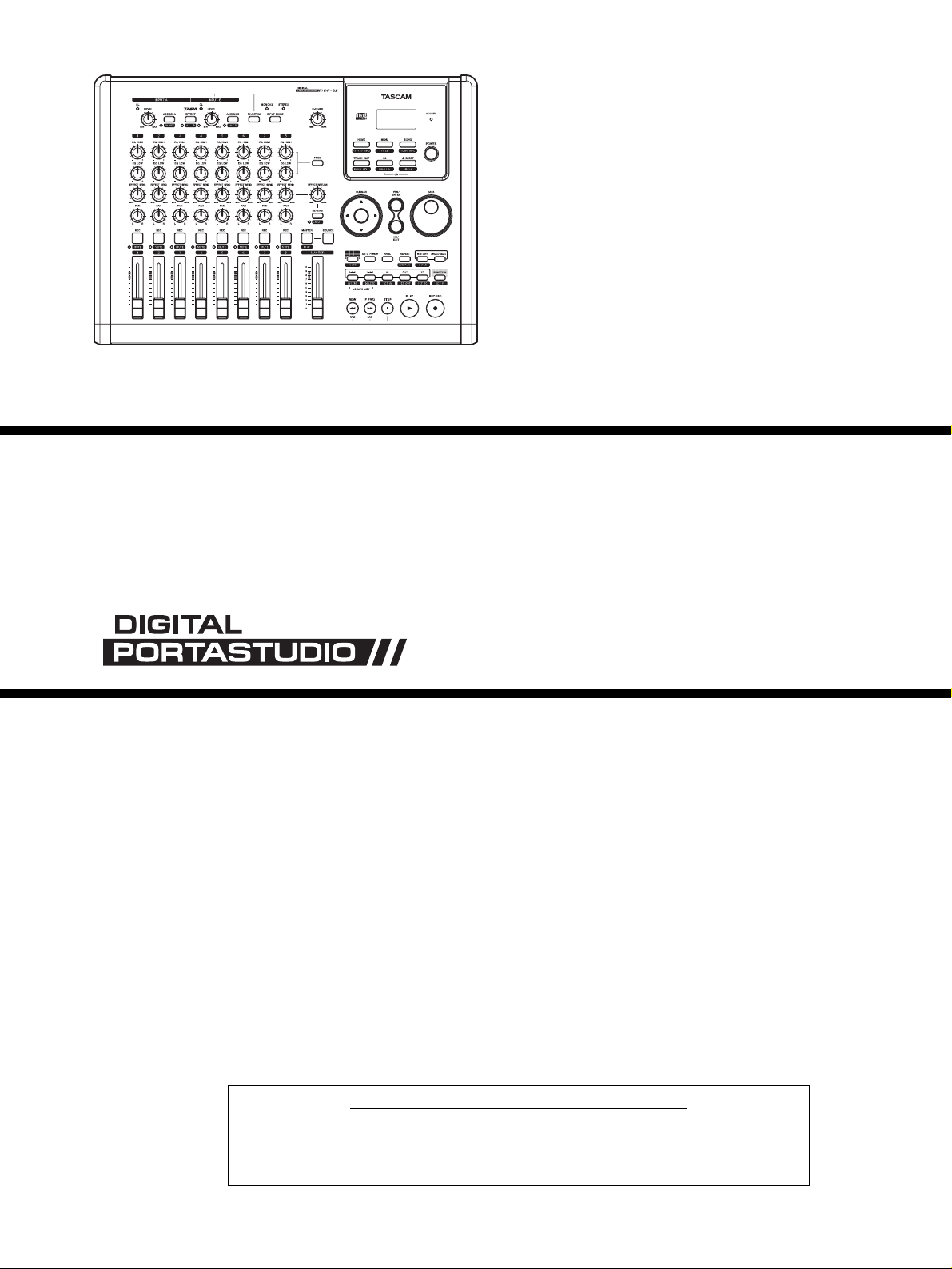
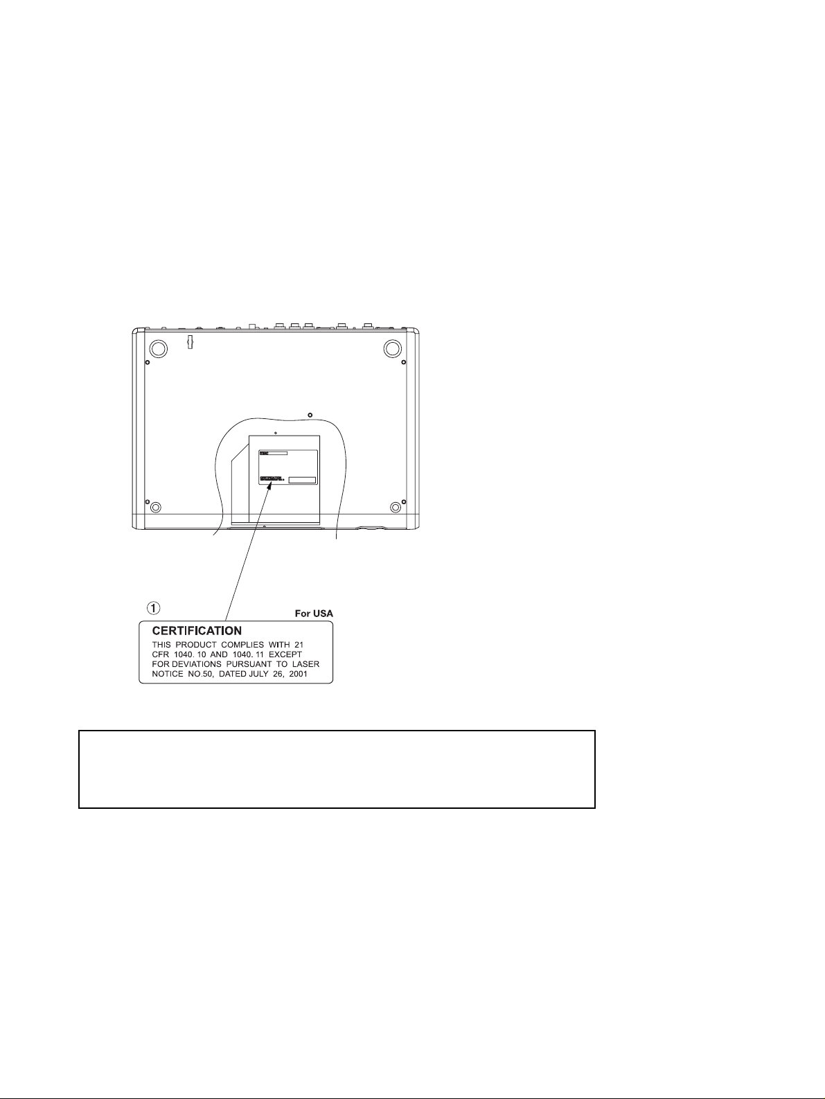
1. SAFETY INFORMATION
TASCAM DP-02/DP-02CF
This product has been designed and manufactured according to FDA regulations "title 21, CFR, chapter 1, subchapter J, based on the
Radiation Control for Health and Safety Act of 1968", and is classified as a class 1 laser product. There is no hazardous invisible laser
radiation
during operation because invisible laser radiation emitted inside of this product is completely confined in the protective housings.
The label required in this regulation is shown .
ºCAUTION
USE OF CONTROLS OR ADJUSTMENT OR PERFORMANCE OF PROCEDURES OTHER THAN THOSE SPECIFIED HEREIN MAY RESULT IN
HAZARDOUS RADIATION EXPOSURE.
Type : HOP-6201T
Optical pickup: Manufacturer : Hitachi Media Electronics Co,Ltd
Laser output : Less than 75 mW on the objective lens(record)
Wavelength : 777 to 787 nm
Page 3

−3−
2. Specifications
仕様
TASCAM DP-02/DP-02CF
Analog specifications
INPUTs (A and B)
1/4" phone (unbalanced)
Input impedance >10 kΩ (A and B), or 1 MΩ (A only)
with switch in GUITAR position
Nominal input level -44dBV ~ -4dBV
Maximum input level +12 dBV
XLR balanced
Input impedance 2.4 kΩ
Nominal input level -48dBV ~ -8dBV
Maximum input level +8 dBu
EFFECT RETURN(L,R) 2 x 1/4" phone (unbalanced)
Input impedance >10 kΩ
Nominal input level –10 dBV
Maximum input level +6 dBV
STEREO MIX(L,R) ø3.5 stereo mini jack (unbalanced)
Input impedance >10 kΩ
Nominal input level –10 dBV
Maximum input level +6 dBV
LINE OUT(L,R) 2 x unbalanced RCA (pin) jacks
Output impedance 1 kΩ
Nominal output level –10 dBV
Maximum output level +6 dBV
EFFECT SEND 1 x 1/4" phone (unbalanced)
Output impedance 1 kΩ
Nominal output level –10 dBV
Maximum output level +6 dBV
PHONES 1/4" stereo jack
Maximum output 25 mW + 25 mW (into 30Ω)
Digital specifications
DIGITAL OUT Optical digital audio output
(TOSLINK)
Data format S/PDIF 1
Audio performance
Frequency response 20 Hz – 20 kHz, +1 dB/–3 dB
Signal-to-noise ratio > 85 dB (A-weighting, 22 kHz LPF)
Total harmonic distortion < 0.02% (1 kHz, –10 dBV, 22 kHz
LPF, MASTER fader at nominal)
アナログ入出力
INPUT(A、B)
標準ホンジャック(アンバランス)入力
入力インピーダンス 10kΩ以上(INPUTB、および
INPUTAの切換スイッチを
MIC/LINEに設定時)
1MΩ(INPUTA、切換スイッチ
を"GUITAR"に設定時)
規定入力レベル −44dBV〜−4dBV
最大入力レベル +12dBV
XLRコネクター入力(バランス)
入力インピーダンス 2.4kΩ
規定入力レベル −48dBu〜−8dBu
最大入力レベル +8dBu
RETURN(L、R)
コネクター 標準ホンジャック(アンバランス)
入力インピーダンス 10kΩ以上
規定入力レベル −10dBV
最大入力レベル +6dBV
STEREOMIX(L、R)
コネクター φ3.5ステレオミニジャック
(アンバランス)
入力インピーダンス 10kΩ以上
規定入力レベル −10dBV
最大入力レベル +6dBV
LINEOUTPUT(L、R)
コネクター RCAピンジャック
出力インピーダンス 1kΩ
規定出力レベル −10dBV
最大出力レベル +6dBV
SEND
コネクター 標準ホンジャック(アンバランス)
出力インピーダンス 1kΩ
規定出力レベル −10dBV
最大出力レベル +6dBV
PHONES
コネクター 標準ホンジャック(ステレオ)
最大出力 25mW+ 25mW(30Ω)
デジタル出力
DIGITALOUT
コネクター 角型オプティカル
データフォーマット S/PDIF1
オーディオ性能
周波数特性 20Hz〜 20kHz、+1dB/−3dB
S/N比 85dB以上
(A-weighted、22kHz LPF)
THD(歪率) 0.02%以下(1kHz、−10dBV、
22kHzLPF、MASTERフェー
ダー基準位置)
Page 4
−4−
TASCAM DP-02/DP-02CF
Physical characteristics
External power adapter AC input 100 – 240 V AC,
50/60 Hz
External power adapter output 12V
External power adapter output current 2.5A
Power consumption
DP-02: 11 W
DP-02CF: 8 W
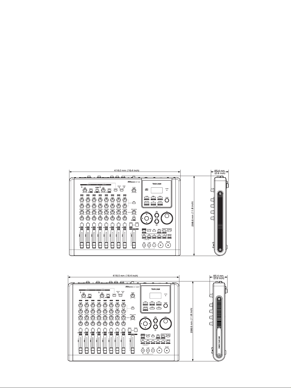
Dimensions (w x h x d)
DP-02/DP-02CF: 416 x 65.4 x 298.6 (mm)
16.4" x 2.6" x 11.8"
Weight
DP-02: 4.5 kg (9.9 lb)
DP-02CF: 4.1 kg (9.0 lb)
一般
電源
ACアダプター入力 AC100− 240V、50Hz−
60Hz
ACアダプター出力電圧 12VDC
ACアダプター出力電流 2.5A
消費電力
DP-02: 11W
DP-02CF: 8W
外形寸法
DP-02: 416(幅)× 65.4(高さ)×
298.6(奥行き)mm
DP-02CF: 416(幅)× 65.4(高さ)×
298.6(奥行き)mm
質量
DP-02: 4.5kg
DP-02CF: 4.1kg
Dimensional drawing
外形寸法図
DP-02
DP-02CF
Page 5
−5−
TASCAM DP-02/DP-02CF
3. Test Mode
テストモード
The DP-02/DP-02CF is provided with a test mode that lets you
run diagnostic checks on the hardware.
This mode is for use in factory and servicing and is not
accessible by users.
By setting this mode on, you can check functions of the
combination of MAIN PCB and PANEL PCB, see firmware version
information, promptly switch into USB mode, check MIDI
functions, etc. This mode is useful in determining what should be
repaired on the PANEL PCB and MAIN PCB or for checking
functions of a PCB after it has been replaced or for verifying the
firmware version.
1. How to enter test mode
While holding down the BOUNCE+DOWN+EXIT keys, switch the
power on.
NOTE: With the DP-02. if there are error conditions in the DSP
section, the test mode cannot be started.
An error occurrence in the DSP initialization process
causes the following message to appear:
"DSP Init Error"
* This error message is displayed not only in the test mode
start-up process, but also in the normal operation mode startup process.
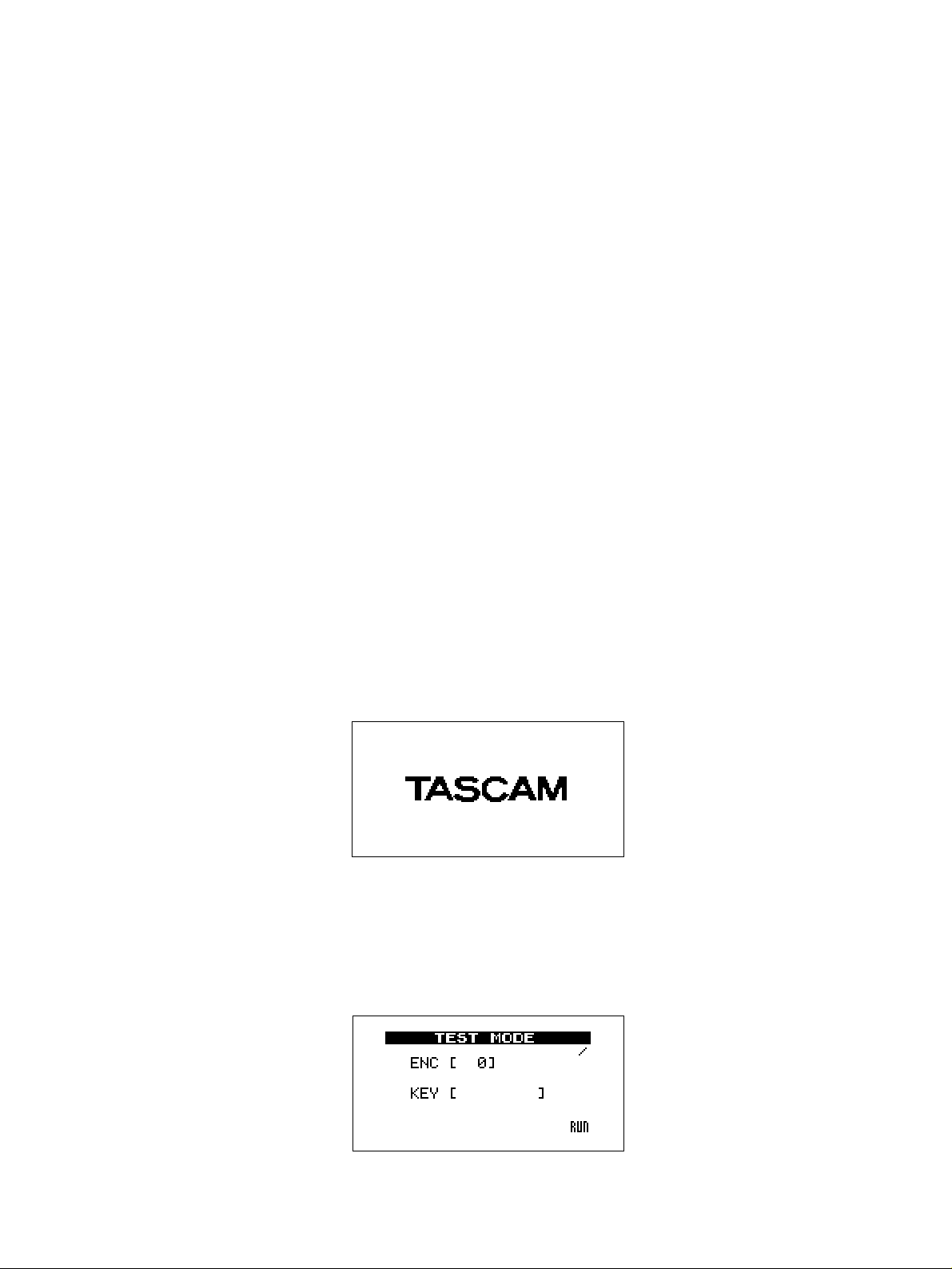
2. When starting up
The LCD shows the following message:
DP-02/DP-02CFではH/Wの自己診断が可能なTEST
MODEを備えています。
このモードは生産、サービス用モードであり、一般公開はし
ません。
自己診断に入ることによりMAIN PCBとPANELPCBの組
み合わせによる動作確認、F/Wの詳細Versionの確認、
USBモードへの素早い移行、MIDI機能確認が行えますので
PANEL PCB、MAINPCBを修理などでチェックする場合
や、PCB交換後のPCB動作確認やF/WのVersion確認時に
有効に使用できます。
1.TESTMODEの起動方法
「BOUNCE+DOWN+EXIT」キーを3個同時に押しながら電
源を投入する。
(注) DP-02ではDSP部のH/Wに異常があるとTEST
MODE起動前にそのエラーで停止します。
DSPの初期化エラーが出た場合、下記を表示します。
"DSPInitError"
※ 上記のエラーメッセージはTEST MODEだけではなく、
通常の起動時にも表示されます。
2.起動時
LCDに下記を表示します。
3. Displays explained
When the test mode starts up, the following are displayed:
3.画面の説明
起動画面後に下記の表示となります。
Page 6
−6−
TASCAM DP-02/DP-02CF
≠ ENC [ 0]: DATA encoder (0-999)
You can determine whether or not each of the three encoders is
in order.
≠ KEY [ ]: Shows the name of a key pressed.
You can determine whether or not a switch pressed is in order.
≠ /: This is an event acceptance indicator.
Normally, this indicator is still and rotates when a key is
operated for example.
4. Checking LEDs
When a key is pressed, its name is displayed in "KEY [ ]" and,
at the same time, the associated LED (except for "ACCESS") turns
on solid or blinks on the PENEL PCB, allowing you to check
whether they work dependably.
1) General
UP: all on
DOWN: all off
RIGHT: blinking at normal speed
LEFT: blinking at higher speed
For the LED associated with a key, it turns on solid when a key is
pressed and starts blinking when holding down the key for a
certain time.
2) Others
MUTE LED: SHIFT+REC1 through REC8
OL A/B: SHIFT+INPUT A/B
The next is on the DP-02 version only.
EFFECT A/B: alternately light when pressing the EFFECT
key.
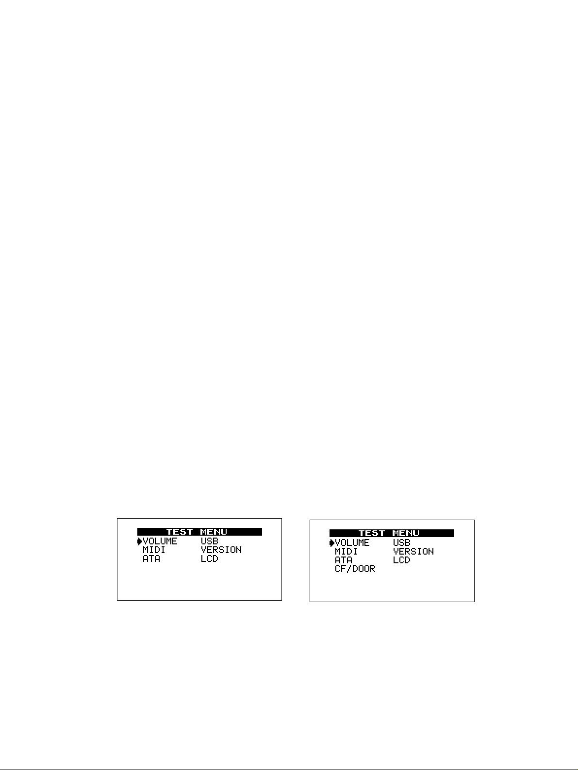
5. Menu
Pressing the MENU key reveals the following menu.
≠ ENC[0]:DATAエンコーダ(0〜999)
エンコーダが正常に動作しているかを確認可能。
≠ KEY[ ]:押されたキーの名称を表示。
押されたKeyが正常に認識されているかを確認可能。
≠
""//""
:イベント受付インジケータ。
通常は停止、キーなど操作すると回転。
4.LED確認
KEY[ ]で押されたキーの名称を表示すると同時に
PANEL PCB上のLED([ACCSESS]を除く)も点灯もしくは
点滅し、正常に点灯するか否かの確認が可能となります。
1)一般
UP:全灯
DOWN:全消灯
RIGHT:通常点滅
LEFT:早い点滅
キーとセットで設置してあるLEDに関してはキーを押すと
LEDが点灯し、一定時間以上押し続けると点滅します。
2)その他
MUTELED:SHIFT+REC1〜REC8
OLA/B:SHIFT+INPUTA/B
以下はDP-02専用
EFFECT A/B:EFFECTキーを押すと交互に点灯し
ます。
5.MENU
MENUキーを押すと下記メニューを表示します。
≠ UP/DOWN/RIGHT/LEFT:項目の移動。
≠ ENTER:項目の選択。
≠ EXIT:TOP画面へ。
≠ UP/DOWN/RIGHT/LEFT: cursor movement
≠ ENTER: mode selection
≠ EXIT: back to the TOP screen
DP-02
DP-02CF
Page 7
−7−
TASCAM DP-02/DP-02CF
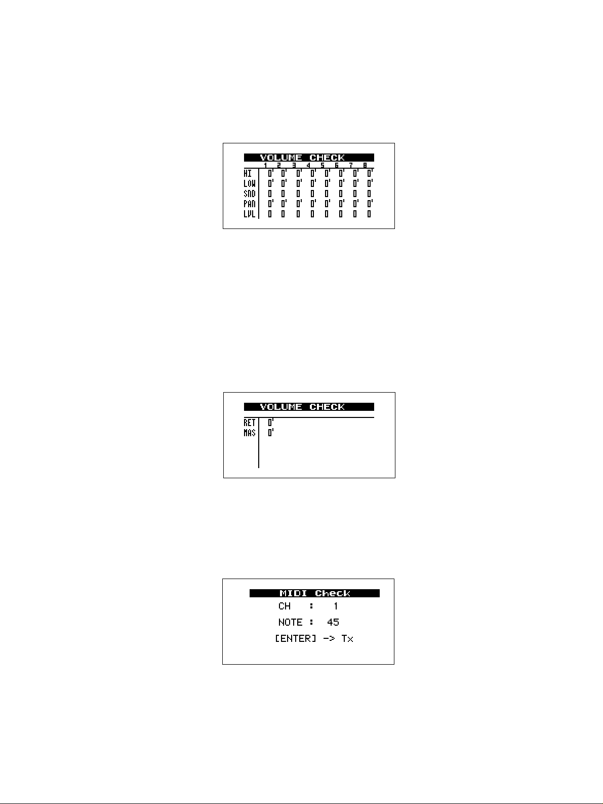
1) VOLUME
When rotating a potentiometer, the number display
changes, allowing you to check whether the
potentiometer is operating correctly.
1)VOLUME
各対応VRを回すとその数値が変化して、VRが正常に
読み取り出来ているかを確認できます。
HI: High Frequency EQ
LOW: Low Frequency EQ
SND: Send
PAN: Panning
LVL: Fader
(Page switching)
The LEFT/RIGHT key lets you move back and forth
through pages.
There are two pages (1 and 2).
Page 1: CH1-CH8
Page 2: Return and Master Fader
HI:EQHIGH
LOW:EQLOW
SND:SEND
PAN:PAN
LVL:FADER
(ページ)
LEFT/RIGHTキーでページ切り替えができます。
ページ1とページ2があります。
ページ1:CH1〜CH8
ページ2:リターン&マスターフェーダ
RET: Return
MAS: Master Fader
2) MIDI
This option lets you check the MIDI OUT function.
RET:RETURN
MAS:MASTERFADER
2)MIDI
MIDIOUT動作の確認が可能となります。
ENTER: Transmits MIDI messages using the channel and
note displayed.
UP/DOWN: Lets the note number display change in +/-12
steps.
LEFT/RIGHT: Increments the channel number by 1.
ENTER:表示されているCHとNOTEで送信します。
UP/DOWN:NOTEの数値が±12の単位で変化し
ます
LEFT/RIGHT:CHが1CHずつ変化します
Page 8
−8−
TASCAM DP-02/DP-02CF
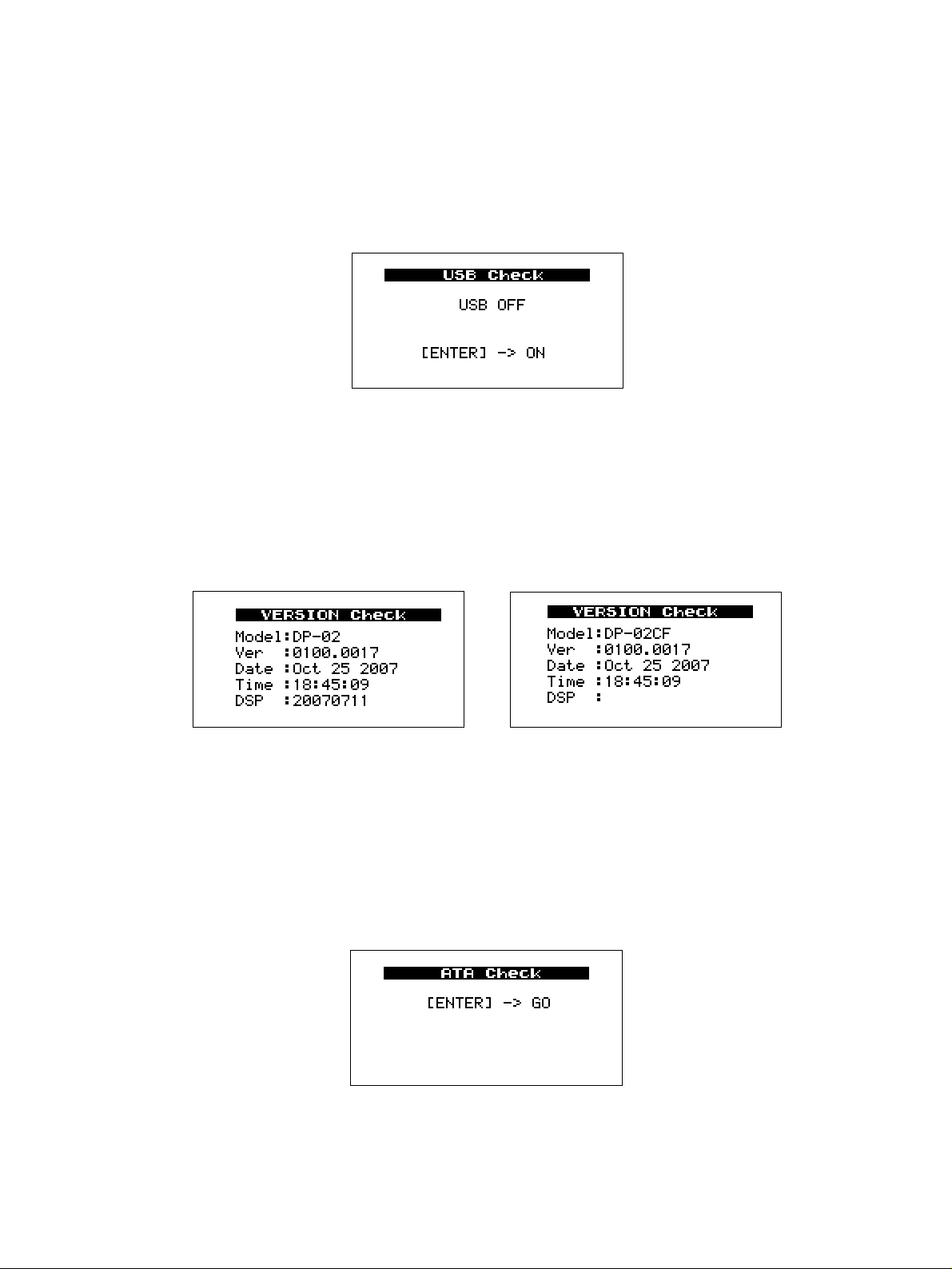
3) USB
This option lets you check whether the USB PCB is
recognized or promptly switch into the USB mode
(promptly, because it is not necessary to access the hard
disk drive).
3)USB
USB PCBの認識状況確認、USBモードへの素早い
移行が可能となります。(通常のHDDアクセスをしな
い為。)
At each press of the ENTER key the USB mode is
switched on/off. Switch the USB mode on is enable the
USB connection, and switch the mode off is disable the
connection.
4) VERSION
When you select this option, the following are displayed,
allowing you to check on the firmware information.
ENTERキーを押すたびにON/OFFを繰り返す。ON
表示でUSB接続、OFF表示でUSB切断となります。
4)VERSION
下記が表示され、F/Wの詳細Version確認が可能とな
ります。
Ver: Version of the system firmware. The last 4 digits
indicate a build number.
Date: on which the system firmware was built.
Time: at which the system firmware was built.
DSP: DSP code version (displayted only on the DP-02)
Ver: システムファームのバージョン。後半の4桁
はビルド番号
Date: ファームビルド日付
Time: ファームビルド時刻
DSP: DSPコードバージョン(DP-02のみ表示さ
れる)
又は
OR
DP-02
DP-02CF
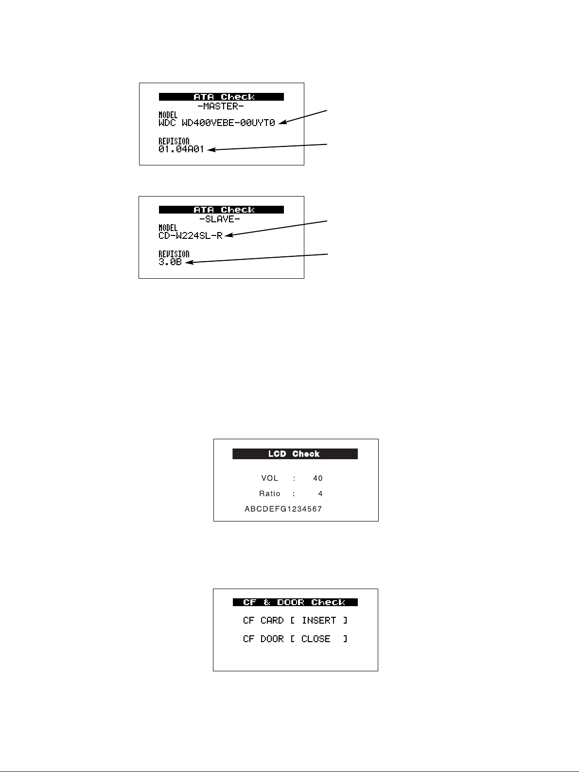
5) ATA :
5)ATA:
ENTERキーを押すと、MASTERとSLAVEのドライ
ブ情報を収集。(DP-02CFの場合はMASTERのみ)
※ENTERを押すと同時にバスリセットを行うので、
短い間隔で連続して行わないように注意。
Press the ENTER key and the unit retrieves information
on the Master and Slave drives (with the DP-02CF, only
information on the master drive is retrieved).
* The bus is reset at each press of the ENTER key. So do
not press the key at short intervals.
Page 9
−9−
TASCAM DP-02/DP-02CF
CFCARD: CFカード挿入時にINSERT、 排出時に
EJECTと表示
CFDOOR: CFDOORのOPEN/CLOSEを表示
RIGHT:SLAVEの画面へ移動。
Right arrow key : reports information on the slave drive.
LEFT:MASTERの画面へ移動。
Left arrow key : reports information on the master drive.
モデル名
Modelname
ドライブのF/Wバージョン
Drivefirmwareversion
モデル名
Modelname
ドライブのF/Wバージョン
Drivefirmwareversion
6)LCD
LCDを選択してENTERを押すと、下記画面を表示す
る。
VOL:コントラスト調整(UP:+ DOWN:− )
Ratio:コントラスト調整傾き(RIGHT:+
LEFT:− )
ABCDEFG1234567:残像確認用キャラクタ
ENTERキー :反転
6) LCD
Select "LCD" and press ENTER and the following are
displayed:
VOL : Contrast adjustment (UP: +; DOWN: -)
Ratio : Tilt adjustment (RIGHT: +; LEFT: -)
ABCDEFG1234567 : Characters for after-image check
ENTER key : Reverse
CF CARD: "INSERT" is displayed when a CF card is
inserted, and "EJECT" is displayed the card is
ejected.
CF DOOR: Indicates that the CF door is closed or opened.
7)CD&DOOR(DP-02CFのみ)
CFCARDの挿入/排出認識、CFDOORのオープン/
クローズ認識ができます。
7) CD & DOOR (DP-02CF only)
This lets you confirm that a CF card is inserted or
ejected, and that the CF door is opened or closed.
Page 10
−10−
TASCAM DP-02/DP-02CF
4. UPDATING SYSTEM FIRMWARE
システムファームウェアアップデート方法
1. Preparations
1) Set this unit for “USB OPEN“ and connect it to a PC using a
USB cable.
2) Place the update file in the UTILITY folder in the unit.
3) Operate the PC to “REMOVE“ the USB device, and set this
unit for “USB CLOSE“ and switch the power off.
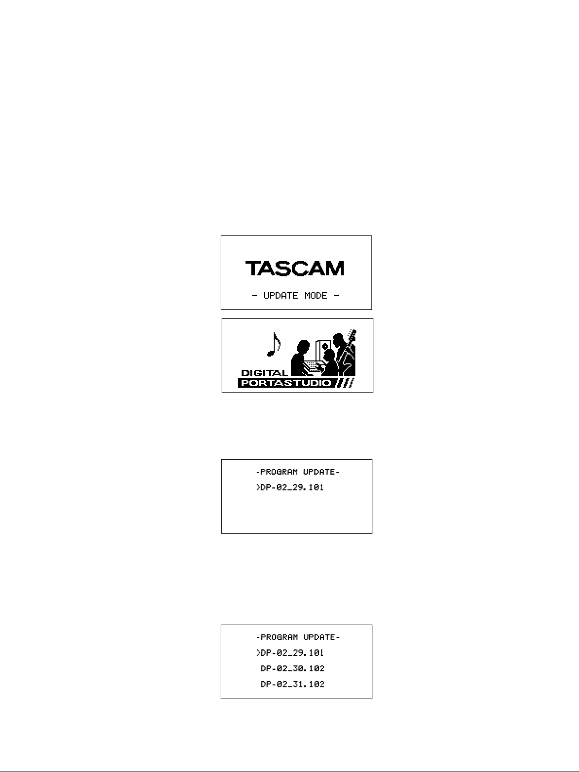
2.Start-up
While holding down the ENETR+EXIT keys, switch the power on.
The LCD looks like this:
1.準備
1)本体を「USB OPEN」状態にしUSBケーブルでPCと接
続します。
2)アップデートファイルを本体の「UTILITY」フォルダに
置きます。
3)PCでUSBデバイスの「取り外し」を行い、本体を
「USBCLOSE」状態にし電源を落とします。
2.起動
ENTER+EXITキーを押しながら電源を投入します。
LCDに下記を表示します。
3.画面の説明
起動後に下記の表示となります。
1)ファイルが一つの場合
2) ファイルが複数の場合
※ 現在のファームウェアバージョンが1.00の場合、文
字が左上寄りに表示され、表示行は最大3行です。
ファームウェアバージョンが1.01以降の場合、表示行
は最大5行です。
表示最大行を超えるファイルがある場合は上下キーまたはダ
イヤルでカーソルが移動します。
3. Displays explained
Upon start-up, the display shows the following.
1) When only a single file is available:
2) When multiple files are available:
* With the version 1.00 firmware, letters are displayed at
upper left, and a maximum of 3 lines is displayed.
With the firmware version 1.01 and later, a maximum of 5
lines is displayed.
If there are files exceeding the maximum display limit, you can
move the cursor using the up/down key or the dial.
Page 11
−11−
TASCAM DP-02/DP-02CF
3) ファイルが無い場合
何も操作できません。
4.ファイルの確認
ENTERキーを押します。
5.アップデート実行
ENTERキーかEXITキーを押します。
1)ENTERキーの場合
アップデートを実行。
2) EXITキーの場合。
3.のファイル選択画面へ戻ります。
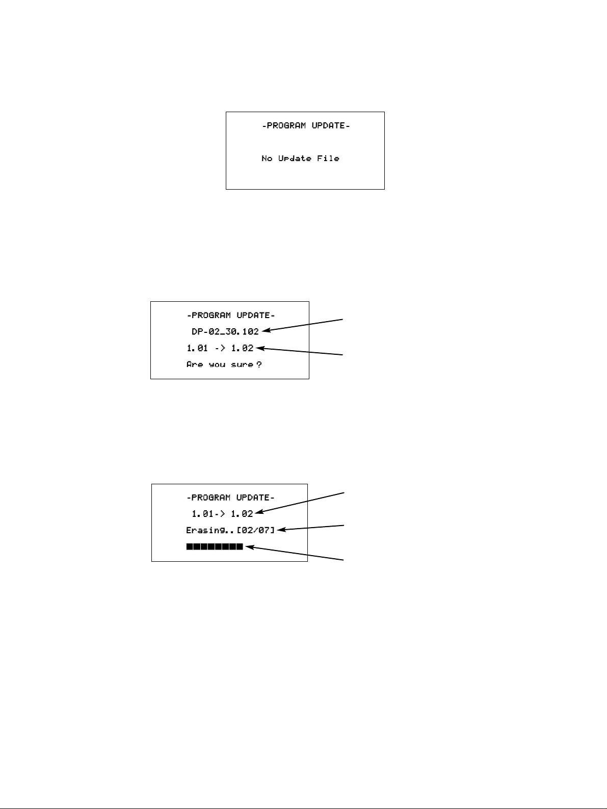
3) When no file is available
You can do nothing.
4. File confirmation
Press the ENTER key.
5. Getting update started
Press the ENTER key, or the EXIT to abort.
1) When ENTER is pressed
The update is carried out.
2) When the EXIT key is pressed
This brings you back to step 3, the display being switched back to
the file selection screen.
選択したファイル名
Nameofthefileselected
左:現バージョン 右:新バージョン
CurrentversionatleftandNewversionatright
左:現バージョン 右:新バージョン
CurrentversionatleftandNewversionatright
左:動作状況、[02/07]:FLASHのセクタ番号
Taskprogress.[02/07]:FLASHsectornumber
セクタ単位の書き込み進捗(現在のファームウェアバー
ジョンが1.00の場合、■ではなく、@で表示されます)
Writingprogressbysector
Page 12

−12−
TASCAM DP-02/DP-02CF
6. Completion
"Complete" and "POWER OFF" are displayed and the unit
automatically powers off.
Recycle the power and check the version information.
7.Error messages
1) If an error occurs when selecting a file, the following
messages appear:
"Product": The product ID of the file does not match (the file
may be for other products).
"Old Version": The file version is older than the current one.
"Checksum": The checksum does not match.
"Update File": Error in file reading
2) If an error occurs in the data rewriting process, the
following messages appear:
"Flash Erase": Error in erasing
"Flash Blank": Blank error as a result of data erasure.
"Flash Write": Error in writing
"Flash Verify": Error in verification after data has been written.
6.完了
「Complete」「POWEROFF」と表示後、自動的に電源OFF
となります。
再度、電源投入しバージョンを確認。
7.エラー
1)ファイル選択時にエラーが発生した場合のメッセージ
"Product": ファイルのプロダクトIDが一致しない(別
製品のファイルの可能性があります
"OldVersion": 現バージョンよりもファイルのバージョン
が古い
"Checksum": ファイルのチェックサムが一致しない
"UpdateFile": ファイル読み込みエラー
2) 書き換え時にエラーが発生した場合のメッセージ
"FlashErase": 消去エラー
"FlashBlank": 消去後のブランクエラー
"FlashWrite": 書き込みエラー
"FlashVerify": 書き込み後のベリファイエラー
Page 13
−13−
TASCAM DP-02/DP-02CF
5. How to initialize HDD/CF CARD
HDD/CFCARD初期化方法
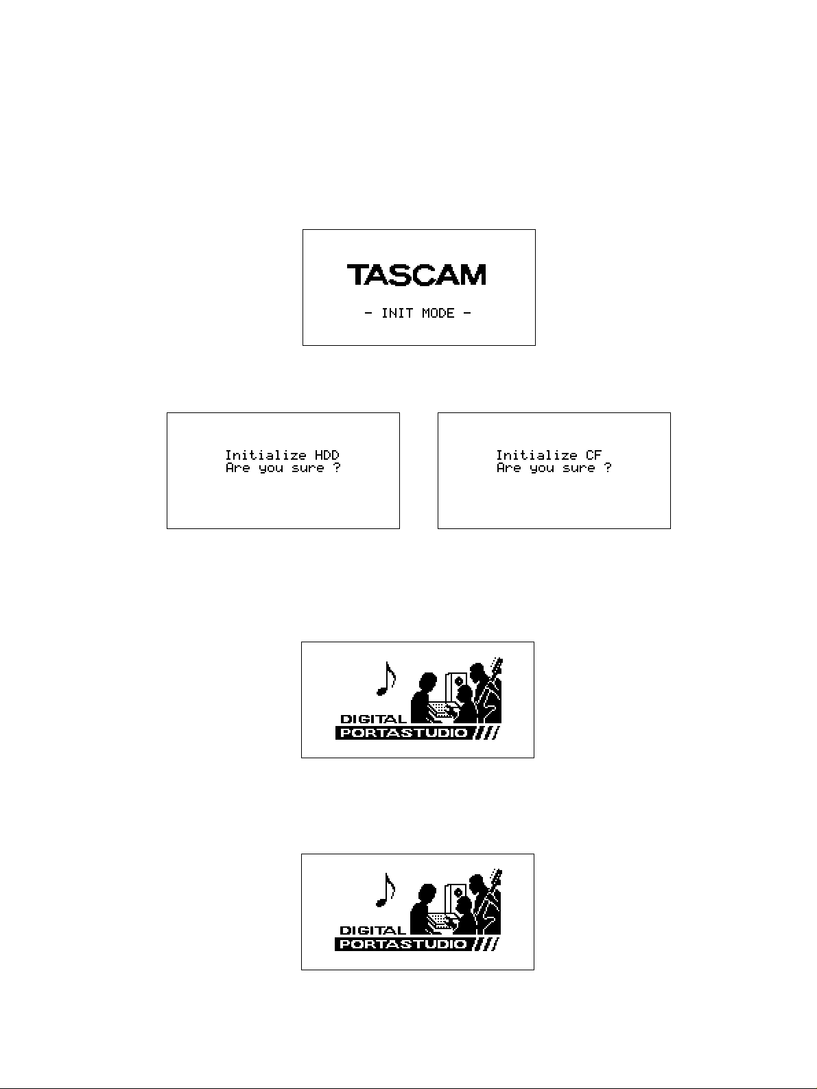
1. Start-up
While holding down the EDIT+UP keys, switch the power on.
2. During start-up
The LCD shows the following:
1.起動方法
EDIT+UPキーを押しながら電源を投入します。
2.起動時
LCDに下記を表示します。
4. Getting initialization started
Press the ENTER key, or the EXIT key to abort.
1) When ENTER pressed:
4.実行
ENTERキーかEXITキーを押します。
1)ENTERキーの場合
The normal start-up screen appears and, when the hard
disk drive/ CF card initialization process is over, the unit
starts up.
2) When EXIT pressed:
通常起動画面となり、HDD/CF CARDの初期化処理
実行後、起動します。
2)EXITキーの場合
3. Prompt
This display prompts you for confirmation.
3.確認画面
確認画面の表示となります。
The normal start-up screen appears and the unit starts up
without going through the hard disk drive/CF card
initialization process.
通常起動画面となり、HDD/CF CARD初期化処理を
しないで起動します。
DP-02
DP-02CF
Page 14

−14−
TASCAM DP-02/DP-02CF
5. Completion
5.完了
The display is switched to show the HOME screen.
HOME画面になり終了します。
Page 15
−15−
6. Precautions when handling CD-W224SL (Thin Drive)
CD-W224SL(薄型ドライブ)取り扱い上の注意
TASCAM DP-02/DP-02CF
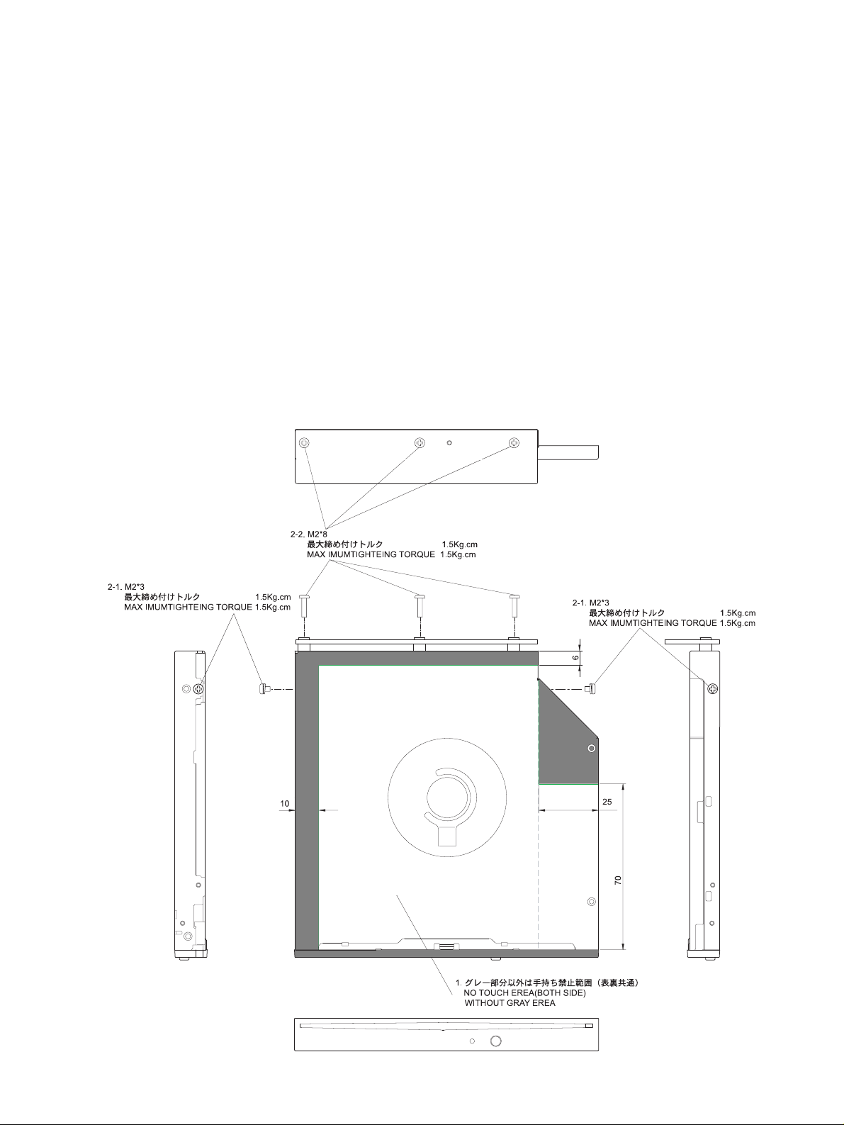
Note the following when handling CD-W224SL
(thindrive).
1. Portions you can hold by hand during removal and
mounting operations
Perform the removal and mounting operations by holding the
grayed portions shown below. It is prohibited to hold other
areas than the grayed ones.
2. Tightening torque limitations during mountingoperations
Note that the screws will be stripped when tightening them
beyond the torque limits.
2-1 When mounting the drive
At lateral 2 points M2*3 1.5kg.cm and below
2-2 When mounting the PCB
At rear 3 points M2*8 1.5kg.cm and below
CD-W224SL(薄型ドライブ)を取り扱う場合は、
下記に注意してください。
1. 取り外し、取り付け時の手持ち可能な範囲
取り付け、取り外しの場合は下図に指示したグレー部分
を持って作業してください。グレー部分以外を持つこと
は禁止されています。
2. 取り付け時のねじの締め付けトルクの制限トルク制限を
超えて締めた場合は、ねじが利かなくなりますので注意
してください。
2-1 ドライブ取り付け
側面2箇所 M2*3 1.5Kg.cm以下
2-2 PCB取り付け
後部3箇所 M2*8 1.5Kg.cm以下
Page 16

−16−
7. Drive Firmware Update
DRIVEファームウェアアップデート
TASCAM DP-02/DP-02CF
1) Creating an update CD
- Prepare a blank CD-R disc, as well as a system capable of
creating data CDs.
- Download the latest version of the firmware from a given
location to PC available.
- Use the "Disc at once" method that complies with ISO9660
Level 1: MS-DOS compatible.
- Create an update disc by recording the downloaded file,
"NM30A3AA.tbf" or later files.
NOTE: Be careful that the mains power supply to the unit is
not interrupted during the update process.
Otherwise the drive firmware data can be damaged
and physical replacement of the related Flash Rom
becomes unavoidable.
2) Getting into update mode
While holding down the STOP, RECORD and SYNC REC keys,
switch on the power.
3) Update mode menu options
After entering update mode, use the encoder to select options
and confirm your selection. The following options are provided.
SYSTEM UP
DRIVE UP
4
DRIVE UPDATE PROCEDURE
Select "DRIVE UP" at the menu and update the drive as
follows:
1) Re
cord in advance the updater file on a disc with a volume
label of UPDATE and under a file name of NM3xxxxx.tbf.
2) When "Drv Update?" is displayed, press the ENTER key.
3) "Disc Set" is then displayed and if a disc has been loaded it is
ejected. Insert then the necessary disc.
1) アップデート用ディスク作製。
1「何も書き込まれていないCD-Rメディアと、データ
CDを記録できる環境を用意する。
2 UPDATEする最新バージョンのファームウェアを所定
の場所からダウンロードしPCに取り込む。
3 CD-Rへの記録フォーマットは、ISO9660 Level 1:
MS-DOS互換、Discatonceを使用。
4 DRIVEアップデートディスクとしてダウンロードファ
イルNM30A3AA.tbf、またはそれ以降を記録する。
注意: アップデート中に不用意に電源が切れないための
注意が必要。アップデート中に電源が切れると、
DRIVEのファームウェアデータが破壊され、関連
フラッシュロムの交換が必要となる。
2)アップデートモードへの入り方
「STOP」と「RECORD」と「SYNCREC」キーを押した
まま電源を入れる。
3)アップデートモードメニュー
アップデートモードに入った後、エンコーダで項目を選択し、
決定する。選択項目は以下の通りである。
「SYSTEMUP」
「DRIVEUP」
4) DRIVEアップデート手順
メニューで「DRIVEUP」項目を選択してDRIVEのバー
ジョンアップを実行する。
1)バージョンアップ元のファイルはボリュームラベル
「UPDATE」、ファイル名「NM3xxxxx.tbf」にして、
ディスクに記録しておく。
2)「Drv Update?」と表示されている状態で「ENTER」
キーを押す。
3)「DiscSet」を表示し、ディスクが入っていた場合は自
動的にディスクを排出するので、準備したディスクを挿
入してください。
DP-02内蔵CD-RWドライブのファームウェアアップデート
はドライブ単体でTASCAM CD-RW900SLもしくはCDRW901SLを使用して実施します。
The firmware update of the CD-RW drive built in the DP-02 is
made by using the TASCAM CD-RW900SL or CD-RW901SL.
Page 17

−17−
TASCAM DP-02/DP-02CF
4) "File Check" is displayed and the disc starts being checked
and, when it is identified as an updater file, the current and
update versions are displayed as "xx.xx > xx.xx", then press
the ENTER key to get the update process started.
5) During the update process, "Drive Update" is displayed
blinking and, when the process is over, "Complete" is
displayed.
6) After the update has been completed, switch off the power,
then switch it back on.
* The drive firmware is prohibited in any case from being
updated on firmware whose drive model number differs from
that on the updater disc.
* Getting into version display mode
Hold down the ∆ and ESCAPE keys and switch on the
power. When the version display mode is engaged, use the
encoder to select "Drive" and confirm the selection. The
following are provided.
SYS Ver xx.xx : System microcomputer version
DRV Ver xx.xx : Drive microcomputer version
4)「File Check」と表示中に挿入されたディスクをチェッ
クし、アップデートファイルと認識すると「xx.xx>xx.xx」と現行バージョン、アップデートバージョン表
示するので「ENTER」キーで実行する。
5)実行中は「Drive Update」を点滅表示し「Complete」
表示で終了となる。
6)バージョンアップ後は電源を入れ直して再起動してくだ
さい。
※ DRIVEファームウェアはいかなる場合も、ドライブ型番
が異なるファームウェアでのアップデートを禁止してい
ます。
※ バージョン表示モードへの入り方
「∆」と「ESCAPE」キーを押したまま電源を入れる。
バージョン表示モードに入った後、エンコーダでDRIVE項
目をを選択し、決定する。選択項目は以下の通りである。
「SYSVerxx.xx」 :Systemマイコンバージョン
「DRVVerxx.xx」 :Drive マイコンバージョン
Page 18

−18−
TASCAM DP-02/DP-02CF
8. LIST OF ERROR MESSAGES AND WARNING
エラー・警告一覧
1. Fatal Error
(致命的エラー)
Message Description (内容)
Shut Error
Unrecoverable error in shutdown process
Shutdown時の修復不可能なエラー
HDD Read Busy
Process not completed in time or other trouble in reading data from HDD or CF CARD
or
HDDもしくはCFCARDからの読み込み時、処理が間に合わないなどのエラー
CF Read Busy
HDD Write Busy
Process not completed in time or other trouble in writing data to HDD or CF CARD
or
HDDもしくはCFCARDへの書き込み時、処理が間に合わないなどのエラー
CF Write Busy
Ata I/F Error
Error occurred in the ATA interface
ATAI/F上でのエラー
No Memory Left
No space left in audio management memory
オーディオ管理用メモリを使い尽くした
System Err 50
Other unrecoverable errors
その他の修復不可能なエラー
HDD Not Found
Failure in the retrieval of the drive interface data
or
ドライブI/F情報取得失敗
CF Not Found
Audio Rst Fail
Error in the initialization of the audio file system
AudioFileSystem初期化エラー
SaveParam Fail
Error in the parameter saving
パラメータセーブエラー
Invalid HDD
Disk label discrepancy
DISKLABEL照合不一致
Mount Error:XX
Error in the mount process. "XX" indicates the step up to which the process has progressed.
マウントプロセスでのエラー。XXは処理がどこまで進んだかのステップを表す番号です
No CD Drive
Shows when the unit cannot recognize a CD drive. (DP-02 only)
CDドライブを認識できない場合に表示されます。(DP-02のみ)
Other unrecoverable errors
File Err:XXXXXX "XXXXXX" indicates the step up to which the process has progressed.
「その他の修復不可能なエラー」
XXXXXXは処理がどこまで進んだかのステップを表す番号です
CPU related error
System error: code X "X" indicates a CPU error type.
CPU関連のエラー。XはCPUエラーの種別を表す番号です
"An unsupported CompactFlash card has been inserted."
CF Size Error Use a CompactFlash card larger than 512MB in size.
容量が512MB未満のコンパクトフラッシュカードがセットされています。
DP-02CFでは、容量が512MB以上のカードをお使い下さい。
Page 19

−19−
TASCAM DP-02/DP-02CF
Message Description (内容)
"CompactFlash card has been removed.
CF-Card Error! Turn off the DP-02CF first, then insert a CompactFlash card and restart the unit.
録音・再生中にコンパクトフラッシュカードが取り出されました。
一旦DP-02CFの電源をオフにしてからカードをセットしなおし、再度起動してください。
System Error 50:0
There are errors in the data on the disk."
DISKの内部情報が異常です。
S Reset Error :XX
Error occurred in the ATA Reset."XX" indicates the step up to which the process has progressed.
ATAバスのリセットに失敗しました。XXは処理がどこまで進んだかのステップを表す
番号です
No HDD :XX
HDD not found. "XX" indicates the step up to which the process has progressed.
HDDを認識できません。XXは処理がどこまで進んだかのステップを表す番号です
CF detect err :XX
CF Card not found. "XX" indicates the step up to which the process has progressed.
CFカードを認識できません。XXは処理がどこまで進んだかのステップを表す番号です
HDD Error :XX
Error occurred in the HD Drive initialize."XX" indicates the step up to which the process has
progressed.
HDドライブの初期設定に失敗しました。XXは処理がどこまで進んだかのステップを表す
番号です
CDD Error :XX
Error occurred in the CD Drive initialize."XX" indicates the step up to which the process has
progressed.
CD-RWドライブの初期設定に失敗しました。XXは処理がどこまで進んだかのステップを
表す番号です
Device error :XX
Error occurred in the CF Card initialize."XX" indicates the step up to which the process has
Invalid Card :XX
progressed.
CF Cmd error :XX
CFカード初期設定に失敗しました。XXは処理がどこまで進んだかのステップを表す番号
です
Page 20

−20−
TASCAM DP-02/DP-02CF
2.Warning
(警告)
Message Description (内容)
You're trying to export a track which doesn't have anything recorded on it. Pick another track to
Empty Export Track
export.
「エクスポートトラックが空っぽです。」
何も録音されていないトラックをエクスポートしようとすると表示されます。
You're trying to restore a song when there are no backed-up songs on the partition maybe you hit
File Not Found
the y key by mistake, or you may want to change the partition.
「ファイルが見つかりません。」
FATパーティションにバックアップされたソングがないときに、ソングをリストアしようと
すると表示されます。
You are trying to enter repeat mode, but the time between the IN and OUT points is too short.
I-O Too Short
Make the time longer.
「INポイントとOUTポイントが近すぎます。」
リピートモードに入ろうとするときにINポイントとOUTポイントが近すぎると表示されます。
You're trying to import a WAV file from the FAT partition when there aren't any WAV files there.
Connect the DP-02/DP-02CF to a PC and transfer some files to the FAT partition for import.
Import File Not Found
「インポートするファイルが見つかりません。」
WAVファイルのないFATパーティションからWAVファイルをインポートしようとしています。
DP-02/DP-02CFをパソコンに接続して、インポートするファイルをパソコンから本機のFAT
パーティションに転送してください。
You're trying to import a WAV file from the FAT partition that is too big for the remaining space on
the partition. Free up some space on the (native) partition and try again.
Import File Too Big
「インポートするファイルが大きすぎます。」
パーティションの空きスペースより容量の大きいWAVファイルをFATパーティションからイン
ポートしようとしています。ファイルを削除してパーティションのスペースを拡げてから再度
インポートを試みてください。
You tried to undo an action while in bounce mode. Other actions may also produce this message.
In Bounce Mode
「バウンスモード中です。」
バウンスモード中に禁止操作をしようとしたときに表示されます。
You tried to undo an action while in mastering mode. Other actions may also produce this message.
In Master Mode
「マスタリングモード中です。」
マスタリングモード中に禁止操作をしようとしたときに表示されます。
You pressed the FF key in auto punch mode. Other actions may also produce this message.
In Punch Mode
「パンチイン/アウトモード中です。」
パンチイン/アウトモード中に禁止操作をしようとしたときに表示されます。
You're trying to enter the menu system, set the IN and OUT points, etc. while the REPEAT indicator
In Repeat Mode
is lit. Turn off repeat and try again. Other actions may also produce this message.
「リピートモード中です。」
リピートモード中に禁止操作をしようとしたときに表示されます。
You tried to store more than 999 location marks in a song. delete some location marks and try again.
Mark Full
「ロケーションマークをこれ以上登録できません。」
1つのソング内のロケーションマーク数は最大999までです。新しいロケーションマークを登
録するには、不要なロケーションマークを削除してから行なってください。
Page 21

−21−
TASCAM DP-02/DP-02CF
Message Description (内容)
You've tried to export a mastered mix track when the song doesn't have one. Master the song and
then export the mix.
Master Track Not Found
「マスタートラックが見つかりません。」
マスターミックストラックがソング内に録音されていないときにマスターミックストラックを
エクスポートしようとすると表示されます。
ソングをマスタリングしてから、ミックスをエクスポートしてください。
You tried to export a master track which was too big for the remaining space on the FAT partition.
connect the DP-02/DP-02CF to a computer and free up some space on the FAT partition.
Master Track Too Big
「マスタートラックが大きすぎます。」
FATパーティションの空き容量より大きなマスタートラックをエクスポートしようとしていま
す。DP-02/DP-02CFをパソコンに接続して、FATパーティションの空きスペースを拡げてく
ださい。
You're trying to set up auto-punching with no tracks armed. Arm a track or tracks and try again.
No Armed Track
「録音待機トラックがありません。」
トラックを録音待機にしないでオートパンチイン/アウトモードに入ろうとしています。
録音待機にしてからAUTOPUNCHキーを押してください。
You'll see this message if you try to create a song, but there's not enough space on the partition
to create a song. Free up some space and try again.
No Disk Space
「ディスクスペースがありません。」
パーティションに十分な空きスペースがないときにソングを作成しようとすると、このメッ
セージが表示されます。
You're trying to edit the location mark list when no location marks have been set.
No Locate Mark
「ロケーションマークがありません。」
ロケーションマークが登録されていないときにロケーションマークリストを編集しようとする
と表示されます。
You've tried to use a non-existent master track as the source in a track cloning operation.
Select another source or master the song and try again.
No Master Trk
「マスタートラックが存在しません。」
トラックのクローンを作るとき、存在しないマスタートラックをソースとして選択しようとす
ると表示されます。マスタートラックを作るか、または別のソースを選択してください。
There's nothing for you to redo (nothing's been undone).
No Redo Histry
「Redoのヒストリーがありません。」
Undoを行なっていないため、Redoするべき操作が存在しません。
You're trying to load a song from a partition that has no songs on it. Change partitions.
No Song
「ソングがありません。」
ソングが存在しないパーティションからソングをロードしようとしています。
パーティションを変更してください。
No actions to be undone.
No Undo Histry
「Undoのヒストリーがありません。」
Undoするような操作が存在しません。
The transport is moving (not stopped, but playing back, recording, etc.) and you've pressed a key
such as the BOUNCE key which cannot be used until you press STOP.
Not Stopped
「レコーダーが停止していません。」
レコーダーが停止していないとき、たとえばBOUNCEキーのように停止中でないと受け付け
ないキーを押すと、このメッセージが表示されます。
Page 22

−22−
TASCAM DP-02/DP-02CF
Message Description (内容)
You're trying to do a menu operation while recording is going on. Other actions may also
producethis message.
Now Recording
「レコーディング中です。」
レコーディングを行なっているときにメニュー操作を行なおうとすると表示されます。
他にもレコーディング中に受け付けない操作があります。
You can't clone a track to itself!
Same Track
「同じトラックを指定しています。」
クローントラック設定で、""SrcTrk""と""DstTrk""とで同じトラックを指定すると表示され
ます。
The song is protected and you are trying to change it (record or edit, etc.). Unprotect the song.
Song Protected
「ソングがプロテクトされています。」
プロテクトされているソングに変更(録音、編集など)を加えようとすると表示されます。
変更を加える前にプロテクトを解除してください。
You have 250 songs on one partition. You must delete some before you can create another song.
Too Many Songs
「これ以上ソングを作成できません。」
一つのパーティションが持つことができるソングの数は最大250です。不要なソングを削除
してから、新しいソングを作成してください。
You're trying to import a file from the FAT partition to a track that already has recording on it.
You can only import to a blank track.
Track Full
「トラックが録音済みです。」
FATパーティションからすでに録音されているトラックにファイルをインポートしようとする
と表示されます。
You're trying to master with the OUT point at the zero position. Set the OUT point and try again.
Trk Too Short
「トラックが短すぎます。」
ゼロポジションをOUTポイントに設定してマスタリングを行なおうとすると表示されます。
OUTポイントを設定し直してください。
This warning alerts you that the management memory consumption increases when the undo history
exceeds 900 in number. The management memory area may be expanded when executing the History
History 900!! Clear function.
UNDOHISTORYの保存数が900を超えると管理メモリエリア消費が増えるため、警告表示さ
れます。HISTORYCLEARを実行することで管理メモリエリアが増える場合があります
"The memory for song recording/editing is full"
Some song memory may be freed up for further recording by pressing SHIFT+CLEAR to delete unused
Memory Poor
data such as the operation history of cuts, copies, etc.
SONGの録音や編集のために必要なメモリエリアがいっぱいになりました。
HISTORYCLEARを実行することにより、録音や編集処理を続けられる場合があります。
"The partition used for song recording has no remaining empty space."
Some song memory may be freed up for further recording by pressing SHIFT+CLEAR to delete unused
data such as the operation history of cuts, copies, etc.
This situation may also be resolved by erasing a song (or songs). This frees up new space for
recording. Remember to back up the song (or songs) before erasing.
No Free Disk
録音中にパーティションの空き領域がなくなりました。
HISTORYCLEARを実行することにより、録音を続けられる場合があります。
また、SONGをERASEすることで空き領域を増やすことができます。
※ERACEする前には必ずSONGBACKUPを行ってください。
Page 23

−23−
TASCAM DP-02/DP-02CF
Message Description (内容)
Undo Fail!
The "Undo" could not be performed.
Undoできませんでした。
Redo Fail!
The "Redo" could not be performed.
Redoできませんでした。
No CF Card!Please set a CF
You tried to record or play or use menu functions despite the compact flash card not being set in place.
コンパクトフラッシュカードがセットされていない状態で録音や再生、またはメニュー機能等を
実行しようとしました
Invalid Card!Please format
You tried to record or play despite the compact flash card not being formatted using the DP-02CF.
コンパクトフラッシュカードがDP-02CFでフォーマットされていない状態で録音や再生等を
実行しようとしました
CF Door is open Please close
You tried to record or play or use menu functions despite the CF door being opened.
CFDOORが開いている状態で録音や再生、またはメニュー機能等を実行しようとしました
! CAUTION ! Close CF door!
The CF door is opened during record or play.
録音・再生中にCFDOORが開けられました
Page 24

−24−
TASCAM DP-02/DP-02CF
9. CD/RW-RELATED ERROR MESSAGES
CD-RW関連エラーメッセージ
Message Description (内容)
Backup Error Press EXIT
An error occurred in the BACKUP execution process.
BACKUP実行の過程でエラーが発生しました。
A CD read error occurred in the FINALIZE, BACKUP, RESTORE, IMPORT, EXPORT, and ERASE
CD Read Error Press EXIT
execution processes.
FINALIZE,BACKUP,RESTORE,IMPORT,EXPORT,ERASE実行の過程でCD読み込み
エラーが発生しました。
CD Write Error Press EXIT
An error occurred in the FINALIZE, BACKUP, RESTORE, and ERASE execution processes.
FINALIZE,BACKUP,EXPORT,ERASE実行の過程でエラーが発生しました。
Erase Error Press EXIT
An error occurred in the ERASE execution process.
ERASE実行の過程でエラーが発生しました。
Export Error Press EXIT
An error occurred in the EXPORT execution process.
EXPORT実行の過程でエラーが発生しました。
Finalize Error Press EXIT
An error occurred in the FINALIZE execution process.
FINALIZE実行の過程でエラーが発生しました。
Import Error Press EXIT
An error occurred in the IMPORT execution process.
IMPORT実行の過程でエラーが発生しました。
Media Error Press EXIT
An error occurred in the CD media in the CD player menu.
CDプレーヤーメニューで、CDメディアにエラーが発生しました。
Restore Error Press EXIT
An error occurred in the RESTORE execution process.
RESTORE実行の過程でエラーが発生しました。
Writing Failed Press EXIT
An error occurred in the CD write process in the MASTER WRITE or CD EXPORT menu.
MASTERWRITE,またはCDEXPORTメニューのCD書き込み過程でエラーが発生しました。
CDメディアの読み取り/書き込みエラーなどにより、CD
関連作業に問題があった場合、以下のポップアップメッセー
ジが表示されます。
表示された場合は、EXITキーを押してメニューから抜け、メ
ディアの状態などを確認後、作業を最初からやり直してくだ
さい。
If you experience a problem while reading or writing a CD, you
may see one of the following error messages:
When a popup message is displayed, press EXIT key to clear the
display, check the state of the media, and retry the operation.
Page 25

−25−
TASCAM DP-02/DP-02CF
メッセージ
以下にポップアップメッセージの一覧表を示します。DP-02
では状況に応じてポップアップメッセージが表示されますが、
それぞれのメッセージの内容を知りたいとき、および対処方
法を知りたいときにこの表をご覧ください。
Messages
The following shows a list of the popup messages. On the DP-02,
popup messages are displayed according to the situation. Refer
to this list to learn the details of each of the messages and how to
remedy the trouble.
Message Description (内容)
"A blank CD has been inserted. Insert a CDRW that is not blank"
An erased CDRW or unwritten CD-R has been inserted in the CDRW ERASE menu.
Blank CD Insert CD-RW
There is no need to erase the inserted CD.
「ブランクのCDがセットされています、ブランクでないCD-RWをセットしてください。」
CD-RWERASEメニューで、消去済みのCD-RWまたは未書き込みのCD-Rがセットされた場合
表示されます。
セットされているCDは消去する必要がありません。
"A blank CD has been inserted. Insert a nonfinalized CD."
An erased CDRW or unwritten CD-R has been inserted in the FINALIZE menu.
Blank CD Insert Opened CD
Insert the CD to be finalized.
「ブランクのCDがセットされています、ファイナライズされていないCDをセットしてください。」
FINALIZEメニューで、消去済みのCD-RWまたは未書き込みのCD-Rがセットされた場合表示
されます。
FINALIZEしたいCDをセットしてください。
"The CDRW will be erased. Insert the CDRW."
The CD was ejected in the CDRW ERASE menu.
CD ERASE Insert CD-RW
Insert the CDRW to erase.
「CD-RWを消去します、CD-RWをセットしてください。」
CD-RWERASEメニューでCDがイジェクトされた場合表示されます。
消去したいCD-RWをセットしてください。
"Insert a blank CD."
The CD was ejected in the CD EXPORT menu.
CD Export Insert Blank CD
Insert a blank CD.
「ブランクCDをセットしてください。」
CDEXPORTメニューでCDがイジェクトされた場合表示されます。
ブランクCDをセットしてください。
"Insert a CD written with import data."
The CD was ejected in the CD IMPORT menu.
CD IMPORT Insert Insert a CD written with import data.
Import CD
「インポートデータが書き込まれたCDをセットしてください。」
CDIMPORTメニューでCDがイジェクトされた場合表示されます。
インポートデータが書き込まれたCDをセットしてください。
Page 26

−26−
TASCAM DP-02/DP-02CF
Message Description (内容)
"Will restore from CD. Insert a CD."
The CD was ejected in the CD RESTORE menu.
CD RESTORE Insert Insert a CD written with backup data.
BackupCD
「CDからリストアします。CDをセットしてください。」
CDRESTOREメニューでCDがイジェクトされた場合表示されます。
バックアップデータが書き込まれたCDをセットしてください。
"There are no exportable tracks"
No audio data is recorded to tracks 1 to 8 in the CD EXPORT menu.
Empty Export Track
「エクスポート可能なトラックがありません。」
CDEXPORTメニューでトラック1-8にオーディオデータが記録されていない場合表示されます。
"Insert the CD to be finalized."
The CD was ejected in the finalize menu.
FINALIZE Insert Opened CD
Insert the CD to be finalized.
「ファイナライズしたいCDをセットしてください。」
ファイナライズメニューで、CDがイジェクトされた場合表示されます。
ファイナライズしたいCDをセットしてください。
"A finalized CD has been inserted. Insert a CDRW that is not blank."
A finalized CD-R has been inserted in the CDRW ERASE menu.
Finalized CD Insert CD-RW
Only CDRW disks can be erased.
「クローズされたCDがセットされています、ブランクでないCD-RWをセットしてください」
CD-RWERASEメニューでファイナライズ済みのCD-Rがセットされた場合表示されます。
CD-RWのみが消去可能です。
"A finalized CD has been inserted. Insert a nonfinalized CD."
A finalized CD has been inserted in the finalize menu.
FinalizedCD Insert This CD does not need to be finalized.
Opened CD
「ファイナライズ済みのCDがセットされています、ファイナライズされていないCDをセット
してください。」
ファイナライズメニューで、ファイナライズ済みのCDがセットされた場合表示されます。
このCDはファイナライズの必要がありません。
"The import file cannot be found. Insert the import CD."
There is no import file in the inserted CD in the CD IMPORT menu.
Import File Not Found
Insert a CD written with import data.
「インポートファイルが見つかりません、インポートCDをセットしてください。」
CDIMPORTメニューでセットされたCDにインポートファイルがない場合表示されます。
インポートデータが書き込まれたCDをセットしてください。
Page 27

−27−
TASCAM DP-02/DP-02CF
Message Description (内容)
"The import file is too big."
The size of the file to import equals or exceeds the free space on hard disk when executing an import
in the CD IMPORT menu.
Create more free space on hard disk by HISTORY CLEAR, for example, to ensure sufficient free space
Import File Too Big
for reading the import file.
「インポートファイルが大きすぎます。」
CDIMPORTメニューでインポートを実行する際、インポートするファイル容量がハードディ
スクの空き容量以上であった場合表示されます。
HISTORYCLEARなどでハードディスク上の空き容量を増やし、ハードディスク上に
インポートファイルを読み込めるだけの空き容量を確保してください。
"An invalid CD has been inserted. Insert the backup CD."
A CD not written with backup data has been inserted in the CD RESTORE menu.
Invalid CD Insert Backup CD
Insert a CD written with backup data.
「無効なCDがセットされています、バックアップCDをセットしてください。」
CDRESTOREメニューで、バックアップデータが書き込まれていないCDがセットされてい
る場合表示されます。
バックアップデータが書き込まれたCDをセットしてください。
"An invalid CD has been inserted. Insert a blank CD."
A CD other than a blank CD has been inserted when writing to CD by the MASTER WRITE, CD BACKUP
or CD EXPORT menu. (This is also displayed when a finalized CD has been inserted when writing by
Track at Once.)
Invalid CD Insert Blank CD
Insert a blank CD.
「無効なCDがセットされています、ブランクCDをセットしてください。」
MASTERWRITE,CDBACKUP,CDEXPORTメニューでCDへの書き込みを行う際、ブラン
クCD以外のCDがセットされている場合表示されます。(TrackatOnceで書き込みを行う場
合は、ファイナライズ済みのCDがセットされた場合もこのメッセージが表示されます。)
ブランクCDをセットしてください。
"An invalid CD has been inserted. Insert a CDRW."
A CD-R or other CD that cannot be erased has been inserted in the CDRW ERASE menu.
Invalid CD Insert CD-RW
Insert a CDRW to be erased.
「無効なCDがセットされています、CD-RWをセットしてください。」
CD-RWERASEメニューで、CD-Rなど消去できないCDがセットされた場合表示されます。
消去したいCD-RWをセットしてください。
"An invalid CD has been inserted. Insert the import CD."
An audio CD, blank CD or other invalid CD has been inserted in the CD IMPORT menu.
Invalid CD Insert Import CD
Insert a CD written with import data.
「無効なCDがセットされています、インポートCDをセットしてください。」
CDIMPORTメニューでオーディオCDやブランクCDなど、無効なCDがセットされた場合表
示されます。
インポートデータが書き込まれたCDをセットしてください。
Page 28

−28−
TASCAM DP-02/DP-02CF
Message Description (内容)
"An invalid CD has been inserted. Insert a nonfinalized CD."
A CD that cannot be finalized has been inserted in the finalize menu.
Invalid CD Insert Opened CD
Insert a CD to be finalized.
「無効なCDがセットされています、ファイナライズされていないCDをセットしてください。」
ファイナライズメニューで、ファイナライズできないCDがセットされた場合表示されます。
ファイナライズしたいCDをセットしてください。
"A CD with low capacity has been inserted. Insert a blank CD with adequate capacity."
The capacity of the CD was less than the data to be written when an attempt was made to make two or
more CDs having the same content after ending MASTER WRITE (Disc at Once) to CD, CD BACKUP or
CD EXPORT. (This message is displayed, for example, when writing is executed with the CD capacity
at 700 MB and the data capacity at 700 MB at the initial write, and a 650 MB CD is inserted after
"Another CD?" is displayedafter writing ends.)
Low Capacity Insert Insert a blank CD having adequate capacity.
Blank CD
「容量の少ないCDがセットされました、適正な容量のブランクCDをセットしてください。」
CDへのMASTERWRITE(DiscatOnce)、CDBACKUPまたはCDEXPORT終了後、さら
に同じ内容のCDを複数作成しようとしたとき、CDの容量が書き込みたいデータ容量以下で
あった場合表示されます。(例えば、最初の書き込み時にCDの容量が700MB/データ容量が
650MBで書き込みを実行し、書き込み終了後AnotherCD?表示の後、640MBのCD
をセットした場合などに表示されます。)
適正な容量のブランクCDをセットしてください。
"Insert a blank CD."
The CD was ejected after preparation for writing to CD was completed in the MASTER WRITE menu.
MASTER WRITE Insert Insert a blank CD and close the CD tray.
Blank CD
「ブランクCDをセットしてください。」
MASTERWRITEメニューでCDへの書き込みを準備完了後、CDがイジェクトされた場合
表示されます。
ブランクCDをセットしてください。
"A CD has not been inserted. Insert the backup CD."
The CD is not inserted in the CD RESTORE menu.
No Disk Insert Backup CD
Insert a CD written with backup data.
「CDがセットされていません、バックアップCDをセットしてください。」
CDRESTOREメニューで、CDが挿入されていない場合表示されます。
バックアップデータが書き込まれたCDをセットしてください。
"A CD has not been inserted. Insert a blank CD."
• There is no CD in the CD tray when writing to a CD in the MASTER WRITE or CD EXPORT menus.
• The CD tray was opened after preparation for backup was completed in the CD BACKUP menu.
No Disk Insert Blank CD
Insert a blank CD and close the CD tray.
「CDがセットされていません、ブランクCDをセットしてください。」
– MASTERWRITE,CDEXPORTメニューでCDへの書き込みを行う際、CDが挿入されて
いない場合表示されます。
– CDBACKUPメニューでバックアップ準備完了後、CDがイジェクトされた場合表示され
ます。
ブランクCDをセットしてください。
Page 29

−29−
TASCAM DP-02/DP-02CF
Message Description (内容)
"A CD has not been inserted. Insert a CDRW that is not blank."
The CD was ejected in the CDRW ERASE menu.
No Disk Insert CD-RW
Insert a CDRW to be erased.
「CDがセットされていません、ブランクでないCD-RWをセットしてください。」
CD-RWERASEメニューで、CDがイジェクトされた場合表示されます。
消去したいCD-RWをセットしてください。
"A CD has not been inserted. Insert the CD to import from."
The CD was ejected in the CD IMPORT menu.
No Disk Insert Import CD
Insert a CD written with the import data.
「CDがセットされていません、インポートするCDをセットしてください。」
CDIMPORTメニューで、CDがイジェクトされた場合表示されます。
インポートデータが書き込まれたCDをセットしてください。
"A CD has not been inserted. Insert a nonfinalized CD."
No Disk Insert Opened CD
The CD was ejected in the finalize menu.
「CDがセットされていません、ファイナライズされていないCDをセットしてください。」
ファイナライズメニューで、CDがイジェクトされた場合表示されます。
"An attempt has been made to write data exceeding the capacity of the CD. Exit the menu."
The total capacity of the specified master track exceeded the capacity of the inserted CD when writing
to CD is started in the MASTER WRITE menu. Press EXIT to exit the menu, and specify the track to
No Room On CD Press EXIT
write to again.
「CDの容量以上のデータが書き込まれようとしました、メニューを抜けてください」
MASTERWRITEメニューでCDへの書き込みを開始時、指定したマスタートラックの合計容量
がセットされたCDの容量以上になった場合表示されます。EXITキーを押してメニューを抜け、
再度書き込むトラックの指定を行ってください。
"Not enough room on hard disk. Exit the menu."
There is no free space to make the CD image file on hard disk when writing to CD is started in the
MASTER WRITE, CD BACKUP or CD EXPORT menus.
Create more free space on hard disk by HISTORY CLEAR, for example, to ensure sufficient free space to
No Room On HD Press EXIT
make the CD image file on the hard disk.
「ハードディスクの容量が不足しています、メニューを抜けてください」
MASTERWRITE,CDBACKUP,CDEXPORTメニューでCDへの書き込みを開始時、ハード
ディスク上にCDイメージファイルを作る空き容量がない場合表示されます。
HISTORYCLEARなどでハードディスク上の空き容量を増やし、ハードディスク上にCDイ
メージファイルを作成できる空き容量を確保してください。
"A nonfinalized CD has been inserted. Insert a blank CD."
A CD written in the Track at Once is inserted when writing by Disc at Once in the MASTER WRITE menu.
Not Blank Insert Blank CD
Either insert a blank CD or write by Track at Once.
「ファイナライズされていないCDがセットされています、ブランクCDをセットしてください」
MASTERWRITEメニューでDiscatOnceの書き込みを行う際、TrackatOnceで書かれた
CDがセットされている場合表示されます。
ブランクCDをセットするか、TrackatOnceで書き込みを行ってください。
Page 30

−30−
TASCAM DP-02/DP-02CF
Message Description (内容)
"No free tracks"
There are no more tracks to import (that is, all tracks are used) when you execute an import in the CD
IMPORT menu.
Track Full
Either import after you have made empty tracks by CLEAN OUT, or import after making a new song.
「空きのトラックがありません。」
CDIMPORTメニューでインポートを実行する際、インポートするトラックがない場合(すべ
てのトラックが使用済み)表示されます。
CLEANOUTで空きトラックを作った後インポートを行うか、新規のソングを作成後インポー
トを行ってください。
"The CD order is wrong. Insert the backup CD."
You have inserted the backup CD in the wrong order while you are restoring from two or more CDs in
the CD RESTORE menu.
Wrong Order Insert Insert the correct backup CD.
Backup CD
「CDの順番が間違っています、バックアップCDをセットしてください。」
CDRESTOREメニューで複数枚のリストアを実行中、BACKUPCDの順番を間違えてセット
した場合表示されます。
適正なバックアップCDをセットしてください。
The data size is too big to restore.
This message alerts you that you tried to perform the "restore" function on the menu while the size of
the data to restore exceeds the free space on the hard disk.
Allocate enough space for the data by increasing the free space on the hard disk using the HISTORY
Restore Data Too Big CLEAR function for example.
「リストアデータが大きすぎます。」
CDRESDTOREメニューでリストアを実行する際、リストアするデータ容量がハードディスク
の空き容量以上であった場合表示されます。
HISTORYCLEARなどでハードディスク上の空き容量を増やし、ハードディスク上にリストア
データを読み込めるだけの空き容量を確保してください。
Page 31

−31−
10. Block Diagram
ブロックダイアグラム
TASCAM DP-02/DP-02CF
Page 32

−32−
11. Level Diagram
レベルダイアグラム
TASCAM DP-02/DP-02CF
Page 33

12. Exploded ViewsI and Parts List
Exploded View-1
−33−
分解図とパーツリスト
TASCAM DP-02/DP-02CF
Please cut DP-02CF.
DP-02CFはカットしてください。
DP-02CF
DP-02CF
Page 34

Exploded View-2
−34−
TASCAM DP-02/DP-02CF
F
DP-02CF
Page 35

Exploded View-1 and 2
REF.NO. PARTSNO. DESCRIPTION REMARKS
1 1J77182R50 CD-W224SL-R50
2 E0144440 FER CORE,A5FS33.5x6.5x12G
3 E95328900A PCB ASSY,MAIN DP02 G...................................................DP-02
3 E95331300A PCB ASSY,MAIN DP02CF G ...............................................DP-02CF
4 E95329000A PCB ASSY,HDD DP02 G
5 E95329100A PCB ASSY,RW DP02 G
6 E95329300A PCB ASSY,PANEL DP02 G.................................................DP-02
6 E95331400A PCB ASSY,PANEL DP02CF G .............................................DP-02CF
7 E95329400A PCB ASSY,LCD DP02 G
8 E95329600A PCB ASSY,CF DP02 G
9 E95329800A PCB ASSY,JACK DP02 G
10 E95329900A PCB ASSY,PHONE DP02 G
11 E95332900A PCB ASSY,SW DP02 G
12 M02190400A CUSHION,PLATE TOP UPPER
13 M02567800A SPACER,SS1-3L G
14 M02594500A CUSHION,AMP GA30 G
15 M02686400B CHASSIS,TOP DP02 G.......................................................DP-02
15 M02686410C CHASSIS,TOP CF G ...........................................................DP-02CF
16 M02686600B BUTTON,DP02 G ...............................................................DP-02CF 2 CUT
17 M02686700A BUTTON,COVER 12 REW G
18 M02686701A BUTTON,COVER 12 FF G
19 M02686702A BUTTON,COVER 12 STOP G
20 M02686800B KNOB,RTRY DO02 GLY/BLK G
21 M02686801B KNOB,RTRY DO02 GRN/BLK G
22 M02686802B KNOB,RTRY DO02 BLU/BLK G
23 M02686803B KNOB,RTRY DO02 ORG/BLK G
24 M02686900A KNOB,SLIDE DP02 GLY/BLK G
25 M02686901A KNOB,SLIDE DP02 RED/BLK G
26 M02687000B WINDOW,LCD DP02 G ......................................................DP-02
26 M02687010B WINDOW,LCD CF G...........................................................DP-02CF
27 M02687500A CHASSIS,CENTER DP02 G
28 M02687600A LINK,DP02 G
29 M02687800A BRACKET,HDD DP02 G
30 M02687900A BRACKET,CDRW DP02 G
31 M02688200B CHASSIS,BOTTOM DP02 G ...............................................DP-02
31 M02688210B CHASSIS,BOTTOM CF G....................................................DP-02CF
32 M02699700A ESCUTCHEON,WINDOW DP02 G
33 M02699800B BUTTON,COVER 19 PLAY G
34 M02699801B BUTTON,COVER 19 REC G
35 M02699900A ESCUTCHEON,FRONT DP02 G...........................................DP-02
35 M02712900A ESCUTCHEON,FRONT CF G ...............................................DP-02CF
36 M02700000A KNOB,JOG BASE G
37 M02700100A POLYEST SHEET,JOG DP02 G
38 M02700200A BUTTON,POWER BASE G
39 M02700400A BUTTON,YN BLK G
40 M02700500A SIDE PANEL,DP02 G
41 M02700510A SIDE PANEL,CF G
42 M02712800A BRACKET,CENTER DP02 G
43 M02713000A BUTTON,CURSOR BASE G
44 M02713100A BUTTON,CURSOR CAP G
TASCAM DP-02/DP-02CF
−35−
Page 36

Exploded View-1 and 2
REF.NO. PARTSNO. DESCRIPTION REMARKS
45 M02713200B PLATE,SIDE DP02 G
46 M02713300B PLATE,SIDE CF G
47 M02713400B COVER,CF G
48 M02713500A KNOB,JOG CAP G
49 M02713600A BUTTON,POWER CAP G
50 M0272180 HDD,HM040HC G
50 T0015780 HARD DISK,WD-400BEVE G..............................................2nd Source
51 M02737400A HIMELON,16*16*0.5 BLK G
52 M02737500A HIMELON,32*16*0.5 BLK G
53 M02750500A SIDE PANEL,CF RIGHT G
54 M02762000A CUSHION,5X16X40 G
55 M02762100A CUSHION,17X16X20 G
56 M02768400A CUSHION,A DP02 G
57 M02768500A CUSHION,B DP02 G
58 T0015900 CF CARD,1GB MLC 80X G
59 3M013100 NUT,M12X2.3-G
60 3M018820 PVC WASHER G
61 3M019930 CLAMP SH3 US-428
62 3M026310 FOOT,SF106R4060 G
63 B0017110 SCREW,DPA 3*6FZB G
64 B0017140 SCREW,BPA 3*6 FZB G
65 B0017150 SCREW,BPA 4*8 FZB G
66 B0017380 SCREW,BPAA 2*8 FZC G
67 B0017400 SCREW,BPA 3*4 FZC G
68 B0019970 SCREW,BPB 3*8 FZB G
69 B0029880 SCREW,BPA 2*3 FZC G
TASCAM DP-02/DP-02CF
−36−
Page 37

−37−
TASCAM DP-02/DP-02CF
GATHER MAIN PCB (SIDE A)
13. PC BOARDS AND PARTS LIST
GATHER MAIN PCB (SIDE B)
Page 38

−38−
TASCAM DP-02/DP-02CF
GATHER PCBA, PANEL (SIDE A)
GATHER PCBA, PANEL (SIDE B)
Page 39

−39−
TASCAM DP-02/DP-02CF
GATHER JACK PCBA
Page 40

−40−
TASCAM DP-02/DP-02CF
GATHER CF PCB (SIDE A) GATHER CF PCB (SIDE B)
Page 41

MAIN PCB ASSY (DP-02(G))
REF.NO. PARTSNO. DESCRIPTION
E95328800A GATHER PCBA,MAIN DP02 G
PCB,MAIN DP02 G
PCB,HDD DP02 G
PCB,RW DP02 G
PCB ASSY,MAIN DP02 G
D102 S0022094 DIODE,1SS355
D103 S0068684 LED,SML-310L TT86 G
D105 S0047674 DIODE,RB160L-60 G
D106 S0015234 DIODE,1SR154-400 TE-25 G
D107 S0022094 DIODE,1SS355
D108 S0015234 DIODE,1SR154-400 TE-25 G
D109 S0074364 DIODE,RB085B-30 G
D110 S0022094 DIODE,1SS355
D111 S0015234 DIODE,1SR154-400 TE-25 G
D113 S0022094 DIODE,1SS355
D114 S0022094 DIODE,1SS355
D115 S0015234 DIODE,1SR154-400 TE-25 G
D116 S0071644 DIODE,RB161M-20 G
D117 S0071644 DIODE,RB161M-20 G
D118 S0023224 DIODE,DAN217 T146 G
D119 S0023224 DIODE,DAN217 T146 G
D120 S0023224 DIODE,DAN217 T146 G
D121 S0023224 DIODE,DAN217 T146 G
D122 S0022094 DIODE,1SS355
D123 S0022094 DIODE,1SS355
D124 S0071644 DIODE,RB161M-20 G
D125 S0015234 DIODE,1SR154-400 TE-25 G
J101 E0140880 JACK,POWER DJ-0702-020 G
J103 E0130730 OPT CONN,GP1FAV51TK0F GZ0
J104 E0124160 MINI DIN JACK,HDC-052A-11 G
J105 E0115760 CONNECTOR,USB UBB4RD14C G
L101 E0140890 COIL,MCDR1419-330K 33UH G
L102 E0124010 COIL,RCR110DNP-102L
L103 E0124024 COIL,ELJPA220KF G
L104 E0140834 COIL,CDRH8D28-100NC G
L105 E0143134 COIL,CDRH6D38NP-6R2NC G
L106 E0126164 BEAD COIL,BLM18PG471SN1D G
L109 E0128324 COIL,ELJPA 100KF G
L110 E0124024 COIL,ELJPA220KF G
L111 E0128324 COIL,ELJPA 100KF G
L112 E0124024 COIL,ELJPA220KF G
L113 E0128324 COIL,ELJPA 100KF G
L114 E0128324 COIL,ELJPA 100KF G
L115 E0128324 COIL,ELJPA 100KF G
L117 E0140474 COIL,CDRH125NP-102MC G
L118 E0126164 BEAD COIL,BLM18PG471SN1D G
L119 E0126164 BEAD COIL,BLM18PG471SN1D G
P101 E0140961 CONNECTOR,S7B-ZR(LF) G
P105 E0143054 CONNECTOR,FH12-50S0.5SH G
MAIN PCB ASSY (DP-02(G))
REF.NO. PARTSNO. DESCRIPTION
P106 E0140951 CONNECTOR,S2B-EHA(LF) G
P107 E0141684 CONNECTOR,S 5B-ZR(LF) G
P108 E0113640 CONNECTOR,S10B-ZR G
P109 E0113630 CONNECTOR,S 9B-ZR G
P110 E0142174 CONNECTOR,F1003WR-S30PB G
P111 E0113560 CONNECTOR,S 2B-ZR G
Q101 S0074414 XSTR,2SA1648-Z-AZ(K/L/M)G
Q102 S0041574 TRANSISTER,DTA124EUA G
Q103 S0065774 TRANSISTOR,2SC3646 G
Q104 S0062132 TRANSISTOR,2SA1020Y G
Q105 S0065074 TRANSISTOR,DTC124EUA TP G
Q106 S0074414 XSTR,2SA1648-Z-AZ(K/L/M)G
Q107 S0029814 TRANSISTOR,DTC123EUA G
Q109 S0071024 TRANSISTER,DTA123EUA G
Q110 S0029814 TRANSISTOR,DTC123EUA G
Q111 S0041574 TRANSISTER,DTA124EUA G
Q112 S0065074 TRANSISTOR,DTC124EUA TP G
Q113 S0071024 TRANSISTER,DTA123EUA G
Q114 S0041574 TRANSISTER,DTA124EUA G
Q115 S0065074 TRANSISTOR,DTC124EUA TP G
Q116 S0075104 TRANSISTOR,KTC2875B G
Q117 S0075104 TRANSISTOR,KTC2875B G
Q118 S0075104 TRANSISTOR,KTC2875B G
Q119 S0065074 TRANSISTOR,DTC124EUA TP G
T101 E0128484 FILTER,956BP-1002=P2 G
U101 S0058774 IC,NJM2374AE G
U102 S0056880 IC,BA033CC0T GZX
U103 S0058774 IC,NJM2374AE G
U104 S0056880 IC,BA033CC0T GZX
U105 S0053584 IIC,NJM78M05DL1A-TE1 GA0
U107 S0065014 IC,SN74LVC2GU04DCKR G
U108 S0063964 IC,PQ1M185M2SPQ G
U109 S0055053 IC,M12L64164A-7T-G
U110 S0065024 IC,BD46285G G
U111 S00757600A IC,ROM ASSY MAIN DP02 G
U111 S0068884 IC,MX29LV400CBTC-70 G
U111 M02764100A LABEL,ROM MAIN DP02 G
U111 D01020300A SOFTWARE SPEC,MAIN DP02 G
U112 S0060143 IC,SCF5249VM140
U113 S0066994 IC,BA2903FVM G
U114 S0075864 IC,CY7C1019DV33-10ZSXI G
U115 S0075043 IC,DSPB56362AG120 G
U116 S0075864 IC,CY7C1019DV33-10ZSXI G
U117 S0061493 IC,XC9536XL-10 VQG44C G
U118 S0075864 IC,CY7C1019DV33-10ZSXI G
U119 S0058774 IC,NJM2374AE G
U120 S0037894 IC,SN74LV04APWR G
U121 S0046854 IC,SN74LV541APWR G
U122 S0046814 IC,SN74LV245APWR G
U123 S0046814 IC,SN74LV245APWR G
TASCAM DP-02/DP-02CF
−41−
Page 42

MAIN PCB ASSY (DP-02(G))
REF.NO. PARTSNO. DESCRIPTION
U124 E0122640 FILTER,DSS6NB32A471Q91A G
U125 E0122640 FILTER,DSS6NB32A471Q91A G
U126 S0064174 IC,PQ1X251M2ZPH G
U127 S0074434 IC,USB97C202-MV-05-E3
U127 S0066493 IC,USB97C202-MV-05 G
U128 S00757800A IC,ROM ASSY USB DP02 G
U128 S0068754 IC,M93C56-WMN6TP G
U128 D01020500A SOFTWARE SPEC,USB DP02 G
U129 S0064724 IC,AK5381ET G
U130 S0064724 IC,AK5381ET G
U131 S0065814 IC,AK4384ET G
U132 S0065814 IC,AK4384ET G
U133 S0064544 IC,NJM4580M G
U134 S0064544 IC,NJM4580M G
U135 S0064544 IC,NJM4580M G
U136 S0053584 IIC,NJM78M05DL1A-TE1 GA0
U137 S0074884 IC,NJM7809DL1A G
X1 E0141174 RESONATOR,11.2896MHZ G
X2 E0141184 RESONATOR,12.0000MHZ G
PCB ASSY,HDD DP02 G
J901 E0143064 CONNECTOR,FH12-50S0.5SV G
J902 E0142780 CONNECTOR,1260050-001-R G
J903 E0143064 CONNECTOR,FH12-50S0.5SV G
P901 E0102430 CONNECTOR,B2B-EH(LF)(SN) G
P902 E0102430 CONNECTOR,B2B-EH(LF)(SN) G
PCB ASSY,RW DP02 G
J904 E0143054 CONNECTOR,FH12-50S0.5SH G
P903 E0140951 CONNECTOR,S2B-EHA(LF) G
P904 E0104604 CONNECTOR,KX14-50K5D1 G
GATHER PCB ASSY, PANEL DP02 G (DP-02(G))
REF.NO. PARTSNO. DESCRIPTION
E95329200A GATHER PCBA,PANEL DP02 G
PCB,PANEL DP02 G
PCB,LCD DP02 G
PCB ASSY,PANEL DP02 G
D701 S0066850 LED,SLR-332VR T32(RED) G
D702 S0067030 LED,SLR-332DU TE7(ORG) G
D703 S0066850 LED,SLR-332VR T32(RED) G
D704 S0067030 LED,SLR-332DU TE7(ORG) G
D705 S0066850 LED,SLR-332VR T32(RED) G
D706 S0067780 LED,SLR-332DU T32(ORG) G
D707 S0067780 LED,SLR-332DU T32(ORG) G
D708 S0067030 LED,SLR-332DU TE7(ORG) G
D709 S0066850 LED,SLR-332VR T32(RED) G
D710 S0067030 LED,SLR-332DU TE7(ORG) G
D711 S0066850 LED,SLR-332VR T32(RED) G
D712 S0067030 LED,SLR-332DU TE7(ORG) G
D713 S0066850 LED,SLR-332VR T32(RED) G
D714 S0067030 LED,SLR-332DU TE7(ORG) G
D715 S0066850 LED,SLR-332VR T32(RED) G
D716 S0067030 LED,SLR-332DU TE7(ORG) G
D717 S0066850 LED,SLR-332VR T32(RED) G
D718 S0067030 LED,SLR-332DU TE7(ORG) G
D719 S0066850 LED,SLR-332VR T32(RED) G
D720 S0066860 LED,SLR-332MG T32(GRN) G
D721 S0067780 LED,SLR-332DU T32(ORG) G
D722 S0067780 LED,SLR-332DU T32(ORG) G
D723 S0067780 LED,SLR-332DU T32(ORG) G
D724 S0067030 LED,SLR-332DU TE7(ORG) G
D725 S0066860 LED,SLR-332MG T32(GRN) G
D726 S0067780 LED,SLR-332DU T32(ORG) G
D727 S0070180 LED,SLR-332MG TE7(GRN)G
D728 S0067030 LED,SLR-332DU TE7(ORG) G
D729 S0067030 LED,SLR-332DU TE7(ORG) G
D730 S0067030 LED,SLR-332DU TE7(ORG) G
D731 S0074392 LED,SLR-332VR TE7(RED) G
D732 S0070180 LED,SLR-332MG TE7(GRN)G
D733 S0067030 LED,SLR-332DU TE7(ORG) G
D734 S0074392 LED,SLR-332VR TE7(RED) G
D735 S0067780 LED,SLR-332DU T32(ORG) G
D736 S0067780 LED,SLR-332DU T32(ORG) G
M02741400A LED SPACER,LEDH-3.5 G
D737 S0022094 DIODE,1SS355
D738 S0022094 DIODE,1SS355
D739 S0022094 DIODE,1SS355
D740 S0022094 DIODE,1SS355
D741 S0022094 DIODE,1SS355
D742 S0022094 DIODE,1SS355
D743 S0022094 DIODE,1SS355
D744 S0022094 DIODE,1SS355
TASCAM DP-02/DP-02CF
−42−
Page 43

GATHER PCB ASSY, PANEL DP02 G (DP-02(G))
REF.NO. PARTSNO. DESCRIPTION
D745 S0022094 DIODE,1SS355
D746 S0022094 DIODE,1SS355
D747 S0022094 DIODE,1SS355
D748 S0022094 DIODE,1SS355
D749 S0022094 DIODE,1SS355
D750 S0022094 DIODE,1SS355
D751 S0022094 DIODE,1SS355
D752 S0022094 DIODE,1SS355
D753 S0022094 DIODE,1SS355
D754 S0022094 DIODE,1SS355
D755 S0022094 DIODE,1SS355
D756 S0022094 DIODE,1SS355
D757 S0022094 DIODE,1SS355
D758 S0022094 DIODE,1SS355
D759 S0022094 DIODE,1SS355
D760 S0022094 DIODE,1SS355
D761 S0022094 DIODE,1SS355
D762 S0022094 DIODE,1SS355
D763 S0022094 DIODE,1SS355
D764 S0022094 DIODE,1SS355
D765 S0022094 DIODE,1SS355
D766 S0022094 DIODE,1SS355
D767 S0022094 DIODE,1SS355
D768 S0022094 DIODE,1SS355
D769 S0022094 DIODE,1SS355
D770 S0022094 DIODE,1SS355
D771 S0022094 DIODE,1SS355
D772 S0022094 DIODE,1SS355
D773 S0022094 DIODE,1SS355
D774 S0022094 DIODE,1SS355
D775 S0022094 DIODE,1SS355
D776 S0022094 DIODE,1SS355
D777 S0022094 DIODE,1SS355
D778 S0022094 DIODE,1SS355
D779 S0022094 DIODE,1SS355
D780 S0022094 DIODE,1SS355
D781 S0022094 DIODE,1SS355
D782 S0022094 DIODE,1SS355
D789 S0066860 LED,SLR-332MG T32(GRN) G
D790 S0067780 LED,SLR-332DU T32(ORG) G
EC701 E0140844 ENCODER,EC12E2440301 G
P701 E0142174 CONNECTOR,F1003WR-S30PB G
P702 E0140961 CONNECTOR,S7B-ZR(LF) G
P703 E0140971 CONNECTOR,S8B-ZR(LF) G
Q701 S0065074 TRANSISTOR,DTC124EUA TP G
Q702 S0065074 TRANSISTOR,DTC124EUA TP G
Q703 S0065074 TRANSISTOR,DTC124EUA TP G
S701 E0127100 SW,TACT SKHHAM2520 G
S702 E0127100 SW,TACT SKHHAM2520 G
S703 E0127100 SW,TACT SKHHAM2520 G
GATHER PCB ASSY, PANEL DP02 G (DP-02(G))
REF.NO. PARTSNO. DESCRIPTION
S704 E0127100 SW,TACT SKHHAM2520 G
S705 E0127100 SW,TACT SKHHAM2520 G
S706 E0127100 SW,TACT SKHHAM2520 G
S707 E0127100 SW,TACT SKHHAM2520 G
S708 E0127100 SW,TACT SKHHAM2520 G
S709 E0127100 SW,TACT SKHHAM2520 G
S710 E0127100 SW,TACT SKHHAM2520 G
S711 E0127100 SW,TACT SKHHAM2520 G
S712 E0127100 SW,TACT SKHHAM2520 G
S713 E0127100 SW,TACT SKHHAM2520 G
S714 E0127100 SW,TACT SKHHAM2520 G
S715 E0127100 SW,TACT SKHHAM2520 G
S716 E0127100 SW,TACT SKHHAM2520 G
S717 E0127100 SW,TACT SKHHAM2520 G
S718 E0127100 SW,TACT SKHHAM2520 G
S719 E0127100 SW,TACT SKHHAM2520 G
S720 E0127100 SW,TACT SKHHAM2520 G
S721 E0127100 SW,TACT SKHHAM2520 G
S722 E0127100 SW,TACT SKHHAM2520 G
S723 E0127100 SW,TACT SKHHAM2520 G
S724 E0127100 SW,TACT SKHHAM2520 G
S725 E0127100 SW,TACT SKHHAM2520 G
S726 E0127100 SW,TACT SKHHAM2520 G
S727 E0127100 SW,TACT SKHHAM2520 G
S728 E0127100 SW,TACT SKHHAM2520 G
S729 E0125781 SW,TACT SKHHDAA010 G
S730 E0125781 SW,TACT SKHHDAA010 G
S731 E0127100 SW,TACT SKHHAM2520 G
S732 E0127100 SW,TACT SKHHAM2520 G
S733 E0127100 SW,TACT SKHHAM2520 G
S734 E0127100 SW,TACT SKHHAM2520 G
S735 E0127100 SW,TACT SKHHAM2520 G
S736 E0127100 SW,TACT SKHHAM2520 G
S737 E0127100 SW,TACT SKHHAM2520 G
S738 E0127100 SW,TACT SKHHAM2520 G
S739 E0127100 SW,TACT SKHHAM2520 G
S740 E0127100 SW,TACT SKHHAM2520 G
S741 E0127100 SW,TACT SKHHAM2520 G
S742 E0127100 SW,TACT SKHHAM2520 G
S743 E0127100 SW,TACT SKHHAM2520 G
S744 E0127100 SW,TACT SKHHAM2520 G
S745 E0127100 SW,TACT SKHHAM2520 G
S746 E0127100 SW,TACT SKHHAM2520 G
S747 E0125781 SW,TACT SKHHDAA010 G
U701 S0065394 IC,SN74LV595APWR G
U702 S0065394 IC,SN74LV595APWR G
U703 S0065394 IC,SN74LV595APWR G
U704 S0065394 IC,SN74LV595APWR G
U705 S0074404 IC,SN74LV4052ANSR G
U706 S0037264 IC,SN74LV4051APWR
TASCAM DP-02/DP-02CF
−43−
Page 44

GATHER PCB ASSY, PANEL DP02 G (DP-02(G))
REF.NO. PARTSNO. DESCRIPTION
U707 S0037264 IC,SN74LV4051APWR
U708 S0037264 IC,SN74LV4051APWR
U709 S0037264 IC,SN74LV4051APWR
U710 S0037264 IC,SN74LV4051APWR
U711 S0051154 IC,SN74LV138APW G
VR701 R0186010 VR,XV9213YNPV20F1B10KC G
VR702 R0186010 VR,XV9213YNPV20F1B10KC G
VR703 R0186000 VR,XV9213YNPV20F1B10K G
VR704 R0186010 VR,XV9213YNPV20F1B10KC G
VR705 R0186010 VR,XV9213YNPV20F1B10KC G
VR706 R0186010 VR,XV9213YNPV20F1B10KC G
VR707 R0186000 VR,XV9213YNPV20F1B10K G
VR708 R0186010 VR,XV9213YNPV20F1B10KC G
VR709 R0186010 VR,XV9213YNPV20F1B10KC G
VR710 R0186010 VR,XV9213YNPV20F1B10KC G
VR711 R0186000 VR,XV9213YNPV20F1B10K G
VR712 R0186010 VR,XV9213YNPV20F1B10KC G
VR713 R0186010 VR,XV9213YNPV20F1B10KC G
VR714 R0186010 VR,XV9213YNPV20F1B10KC G
VR715 R0186000 VR,XV9213YNPV20F1B10K G
VR716 R0186010 VR,XV9213YNPV20F1B10KC G
VR717 R0186010 VR,XV9213YNPV20F1B10KC G
VR718 R0186010 VR,XV9213YNPV20F1B10KC G
VR719 R0186000 VR,XV9213YNPV20F1B10K G
VR720 R0186010 VR,XV9213YNPV20F1B10KC G
VR721 R0186010 VR,XV9213YNPV20F1B10KC G
VR722 R0186010 VR,XV9213YNPV20F1B10KC G
VR723 R0186000 VR,XV9213YNPV20F1B10K G
VR724 R0186010 VR,XV9213YNPV20F1B10KC G
VR725 R0186000 VR,XV9213YNPV20F1B10K G
VR726 R0186010 VR,XV9213YNPV20F1B10KC G
VR727 R0186010 VR,XV9213YNPV20F1B10KC G
VR728 R0186000 VR,XV9213YNPV20F1B10K G
VR729 R0186010 VR,XV9213YNPV20F1B10KC G
VR730 R0186010 VR,XV9213YNPV20F1B10KC G
VR731 R0186010 VR,XV9213YNPV20F1B10KC G
VR732 R0186000 VR,XV9213YNPV20F1B10K G
VR733 R0186010 VR,XV9213YNPV20F1B10KC G
VR734 R0186500 VR,RS45111-92C0P1B103 G
VR735 R0186500 VR,RS45111-92C0P1B103 G
VR736 R0186500 VR,RS45111-92C0P1B103 G
VR737 R0186500 VR,RS45111-92C0P1B103 G
VR738 R0186500 VR,RS45111-92C0P1B103 G
VR739 R0186500 VR,RS45111-92C0P1B103 G
VR740 R0186500 VR,RS45111-92C0P1B103 G
VR741 R0186500 VR,RS45111-92C0P1B103 G
VR742 R0186500 VR,RS45111-92C0P1B103 G
GATHER PCB ASSY, PANEL DP02 G (DP-02(G))
REF.NO. PARTSNO. DESCRIPTION
PCB ASSY,LCD DP02 G
D783 S0023224 DIODE,DAN217 T146 G
D784 S0023224 DIODE,DAN217 T146 G
D785 S0023224 DIODE,DAN217 T146 G
D786 S0023224 DIODE,DAN217 T146 G
D787 S0023224 DIODE,DAN217 T146 G
D788 S0023224 DIODE,DAN217 T146 G
P704 E0140971 CONNECTOR,S8B-ZR(LF) G
Q704 S0029814 TRANSISTOR,DTC123EUA G
Q705 S0071024 TRANSISTER,DTA123EUA G
U712 E01406200A LCD,KMC12864-F-02-SPC G
GATHER PCB ASSY, JACK DP02 G (DP-02(G))
REF.NO. PARTSNO. DESCRIPTION
E95329700A GATHER PCBA,JACK DP02 G
PCB,JACK DP02 G
PCB,PHONE DP02 G
PCB ASSY,JACK DP02 G
D501 S0067021 DIODE,1SS133 T-77 G
D502 S0067021 DIODE,1SS133 T-77 G
D503 S0067021 DIODE,1SS133 T-77 G
D504 S0067021 DIODE,1SS133 T-77 G
D505 S0067021 DIODE,1SS133 T-77 G
D506 S0067021 DIODE,1SS133 T-77 G
D507 S0067021 DIODE,1SS133 T-77 G
D508 S0067021 DIODE,1SS133 T-77 G
D509 S0067021 DIODE,1SS133 T-77 G
D510 S0067021 DIODE,1SS133 T-77 G
J501 E0133140 JACK,064M-4 WITH EARTH G
J502 E0123990 JACK,XLR JY-5033A G
J503 E0123990 JACK,XLR JY-5033A G
J504 E0133140 JACK,064M-4 WITH EARTH G
J505 E0123960 JACK,YKC 21-3487N G
J506 E0133130 JACK,064M WITH EARTHME G
J507 E0133130 JACK,064M WITH EARTHME G
J508 E0136530 JACK,JY-3530-01-030 G
J509 E0133130 JACK,064M WITH EARTHME G
J510 E0113630 CONNECTOR,S 9B-ZR G
J511 E0113580 CONNECTOR,S 4B-ZR G
J512 E0113640 CONNECTOR,S10B-ZR G
J513 E0141684 CONNECTOR,S 5B-ZR(LF) G
Q501 S0064312 FET,2SK117BL(TPE2.F) G
Q502 S0074832 TRANSISTOR,KTC2874BAT/PG
Q503 S0074832 TRANSISTOR,KTC2874BAT/PG
S501 E0140930 SW,SLIDE SSAA120200 G
U501 S0044970 IC,NJM4580L
U502 S0044970 IC,NJM4580L
U503 S0044970 IC,NJM4580L
TASCAM DP-02/DP-02CF
−44−
Page 45

GATHER PCBA, JACK DP02 G (DP-02(G))
REF.NO. PARTSNO. DESCRIPTION
U504 S0044970 IC,NJM4580L
U505 S0044970 IC,NJM4580L
U506 E0122640 FILTER,DSS6NB32A471Q91A G
U507 E0122640 FILTER,DSS6NB32A471Q91A G
U508 E0122640 FILTER,DSS6NB32A471Q91A G
U509 E0122640 FILTER,DSS6NB32A471Q91A G
U510 E0122640 FILTER,DSS6NB32A471Q91A G
U511 E0122640 FILTER,DSS6NB32A471Q91A G
U512 E0122640 FILTER,DSS6NB32A471Q91A G
U513 E0122640 FILTER,DSS6NB32A471Q91A G
U514 E0122640 FILTER,DSS6NB32A471Q91A G
U515 E0122640 FILTER,DSS6NB32A471Q91A G
U516 E0122640 FILTER,DSS6NB32A471Q91A G
U517 E0122640 FILTER,DSS6NB32A471Q91A G
U518 E0122640 FILTER,DSS6NB32A471Q91A G
VR501 R0186540 VR,XV012311GPV20F1B20K G
VR502 R0186540 VR,XV012311GPV20F1B20K G
VR503 R0186530 VR,XV012311GPV20F15A20K G
PCB ASSY,PHONE DP02 G
J601 E0133150 JACK,CPJ-0642M G
J602 E0133130 JACK,064M WITH EARTHME G
J603 E0113580 CONNECTOR,S 4B-ZR G
J604 E0113560 CONNECTOR,S 2B-ZR G
U601 E0122640 FILTER,DSS6NB32A471Q91A G
U602 E0122640 FILTER,DSS6NB32A471Q91A G
U603 E0122640 FILTER,DSS6NB32A471Q91A G
WIRE SECT, DP02(G)
REF.NO. PARTSNO. DESCRIPTION
E01417300A HARNESS ASSY,LCD DP02 G
E01417400A HARNESS ASSY,PANEL DP02 G
E01417500A HARNESS ASSY,A_IN DP02 G
E01417600A HARNESS ASSY,A_OUT DP02 G
E01417700A HARNESS ASSY,A_PWR DP02 G
E01417800A HARNESS ASSY,FRONT DP02 G
E01417900A HARNESS ASSY,IDE_P DP02 G
E01418600A FLAT CABLE,FFC30P P1.0 G
E01418700B FLAT CABLE,FFC50P P0.5 G
E01418800B FLAT CABLE,FFC50PR P0.5 G
E01428100B HARNESS ASSY,PUNCH DP02 G
MAIN PCB ASSY (DP-02CF(G))
REF.NO. PARTSNO. DESCRIPTION
E95331100A GATHER PCBA,MAIN DP02CF G
PCB,MAIN DP02 G
PCB,HDD DP02 G
PCB,RW DP02 G
PCB ASSY,MAIN DP02CF G
D102 S0022094 DIODE,1SS355
D103 S0068684 LED,SML-310L TT86 G
D105 S0047674 DIODE,RB160L-60 G
D107 S0022094 DIODE,1SS355
D108 S0015234 DIODE,1SR154-400 TE-25 G
D109 S0074364 DIODE,RB085B-30 G
D110 S0022094 DIODE,1SS355
D111 S0015234 DIODE,1SR154-400 TE-25 G
D113 S0022094 DIODE,1SS355
D114 S0022094 DIODE,1SS355
D115 S0015234 DIODE,1SR154-400 TE-25 G
D116 S0071644 DIODE,RB161M-20 G
D117 S0071644 DIODE,RB161M-20 G
D118 S0023224 DIODE,DAN217 T146 G
D119 S0023224 DIODE,DAN217 T146 G
D120 S0023224 DIODE,DAN217 T146 G
D121 S0023224 DIODE,DAN217 T146 G
D122 S0022094 DIODE,1SS355
D123 S0022094 DIODE,1SS355
D124 S0071644 DIODE,RB161M-20 G
D125 S0015234 DIODE,1SR154-400 TE-25 G
J101 E0140880 JACK,POWER DJ-0702-020 G
J103 E0130730 OPT CONN,GP1FAV51TK0F GZ0
J104 E0124160 MINI DIN JACK,HDC-052A-11 G
J105 E0115760 CONNECTOR,USB UBB4RD14C G
L101 E0140890 COIL,MCDR1419-330K 33UH G
L102 E0124010 COIL,RCR110DNP-102L
L103 E0124024 COIL,ELJPA220KF G
L104 E0140834 COIL,CDRH8D28-100NC G
L105 E0143134 COIL,CDRH6D38NP-6R2NC G
L106 E0126164 BEAD COIL,BLM18PG471SN1D G
L109 E0128324 COIL,ELJPA 100KF G
L110 E0124024 COIL,ELJPA220KF G
L113 E0128324 COIL,ELJPA 100KF G
L114 E0128324 COIL,ELJPA 100KF G
L115 E0128324 COIL,ELJPA 100KF G
L117 E0140474 COIL,CDRH125NP-102MC G
L118 E0126164 BEAD COIL,BLM18PG471SN1D G
L119 E0126164 BEAD COIL,BLM18PG471SN1D G
P101 E0140961 CONNECTOR,S7B-ZR(LF) G
P105 E0143054 CONNECTOR,FH12-50S0.5SH G
P107 E0141684 CONNECTOR,S 5B-ZR(LF) G
P108 E0113640 CONNECTOR,S10B-ZR G
P109 E0113630 CONNECTOR,S 9B-ZR G
P110 E0142174 CONNECTOR,F1003WR-S30PB G
TASCAM DP-02/DP-02CF
−45−
Page 46

MAIN PCB ASSY (DP-02CF(G))
REF.NO. PARTSNO. DESCRIPTION
P111 E0113560 CONNECTOR,S 2B-ZR G
Q101 S0074414 XSTR,2SA1648-Z-AZ(K/L/M)G
Q102 S0041574 TRANSISTER,DTA124EUA G
Q103 S0065774 TRANSISTOR,2SC3646 G
Q104 S0062132 TRANSISTOR,2SA1020Y G
Q105 S0065074 TRANSISTOR,DTC124EUA TP G
Q106 S0074414 XSTR,2SA1648-Z-AZ(K/L/M)G
Q107 S0029814 TRANSISTOR,DTC123EUA G
Q109 S0071024 TRANSISTER,DTA123EUA G
Q110 S0029814 TRANSISTOR,DTC123EUA G
Q111 S0041574 TRANSISTER,DTA124EUA G
Q112 S0065074 TRANSISTOR,DTC124EUA TP G
Q113 S0071024 TRANSISTER,DTA123EUA G
Q114 S0041574 TRANSISTER,DTA124EUA G
Q115 S0065074 TRANSISTOR,DTC124EUA TP G
Q116 S0075104 TRANSISTOR,KTC2875B G
Q117 S0075104 TRANSISTOR,KTC2875B G
Q118 S0075104 TRANSISTOR,KTC2875B G
Q119 S0065074 TRANSISTOR,DTC124EUA TP G
T101 E0128484 FILTER,956BP-1002=P2 G
U101 S0058774 IC,NJM2374AE G
U103 S0058774 IC,NJM2374AE G
U104 S0056880 IC,BA033CC0T GZX
U105 S0053584 IIC,NJM78M05DL1A-TE1 GA0
U107 S0065014 IC,SN74LVC2GU04DCKR G
U108 S0063964 IC,PQ1M185M2SPQ G
U109 S0055053 IC,M12L64164A-7T-G
U110 S0065024 IC,BD46285G G
U111 S00757700A IC,ROM ASSY MAIN DP02C G
U111 S0068884 IC,MX29LV400CBTC-70 G
U111 M02764200A LABEL,ROM MAIN DP02CF G
U111 D01020400A SOFTWARE SPEC,MAIN DP02C G
U112 S0060143 IC,SCF5249VM140
U113 S0066994 IC,BA2903FVM G
U119 S0058774 IC,NJM2374AE G
U120 S0037894 IC,SN74LV04APWR G
U121 S0046854 IC,SN74LV541APWR G
U122 S0046814 IC,SN74LV245APWR G
U123 S0046814 IC,SN74LV245APWR G
U124 E0122640 FILTER,DSS6NB32A471Q91A G
U125 E0122640 FILTER,DSS6NB32A471Q91A G
U126 S0064174 IC,PQ1X251M2ZPH G
U127 S0074434 IC,USB97C202-MV-05-E3
U127 S0066493 IC,USB97C202-MV-05 G
U128 S00757800A IC,ROM ASSY USB DP02 G
U128 S0068754 IC,M93C56-WMN6TP G
U128 D01020500A SOFTWARE SPEC,USB DP02 G
U129 S0064724 IC,AK5381ET G
U130 S0064724 IC,AK5381ET G
U131 S0065814 IC,AK4384ET G
MAIN PCB ASSY (DP-02CF(G))
REF.NO. PARTSNO. DESCRIPTION
U132 S0065814 IC,AK4384ET G
U133 S0064544 IC,NJM4580M G
U134 S0064544 IC,NJM4580M G
U135 S0064544 IC,NJM4580M G
U136 S0053584 IIC,NJM78M05DL1A-TE1 GA0
U137 S0074884 IC,NJM7809DL1A G
X1 E0141174 RESONATOR,11.2896MHZ G
X2 E0141184 RESONATOR,12.0000MHZ G
GATHER PCBA, PANEL DP02CF G (DP-02CF(G))
REF.NO. PARTSNO. DESCRIPTION
E95331200A GATHER PCBA,PANELDP02CF G
PCB,PANEL DP02 G
PCB,LCD DP02 G
PCB ASSY,PANEL DP02CF G
U701 S0065394 IC,SN74LV595APWR G
U702 S0065394 IC,SN74LV595APWR G
U703 S0065394 IC,SN74LV595APWR G
U704 S0065394 IC,SN74LV595APWR G
U705 S0074404 IC,SN74LV4052ANSR G
U706 S0037264 IC,SN74LV4051APWR
U707 S0037264 IC,SN74LV4051APWR
U708 S0037264 IC,SN74LV4051APWR
U709 S0037264 IC,SN74LV4051APWR
U710 S0037264 IC,SN74LV4051APWR
U711 S0051154 IC,SN74LV138APW G
Q701 S0065074 TRANSISTOR,DTC124EUA TP G
Q702 S0065074 TRANSISTOR,DTC124EUA TP G
Q703 S0065074 TRANSISTOR,DTC124EUA TP G
D737 S0022094 DIODE,1SS355
D738 S0022094 DIODE,1SS355
D739 S0022094 DIODE,1SS355
D740 S0022094 DIODE,1SS355
D741 S0022094 DIODE,1SS355
D742 S0022094 DIODE,1SS355
D743 S0022094 DIODE,1SS355
D744 S0022094 DIODE,1SS355
D745 S0022094 DIODE,1SS355
D746 S0022094 DIODE,1SS355
D747 S0022094 DIODE,1SS355
D748 S0022094 DIODE,1SS355
D749 S0022094 DIODE,1SS355
D750 S0022094 DIODE,1SS355
D751 S0022094 DIODE,1SS355
D752 S0022094 DIODE,1SS355
D753 S0022094 DIODE,1SS355
D754 S0022094 DIODE,1SS355
D755 S0022094 DIODE,1SS355
D756 S0022094 DIODE,1SS355
D757 S0022094 DIODE,1SS355
TASCAM DP-02/DP-02CF
−46−
Page 47

GATHER PCB ASSY, PANEL DP02CF G (DP-02CF(G))
REF.NO. PARTSNO. DESCRIPTION
D758 S0022094 DIODE,1SS355
D759 S0022094 DIODE,1SS355
D760 S0022094 DIODE,1SS355
D761 S0022094 DIODE,1SS355
D762 S0022094 DIODE,1SS355
D763 S0022094 DIODE,1SS355
D765 S0022094 DIODE,1SS355
D766 S0022094 DIODE,1SS355
D767 S0022094 DIODE,1SS355
D768 S0022094 DIODE,1SS355
D769 S0022094 DIODE,1SS355
D770 S0022094 DIODE,1SS355
D771 S0022094 DIODE,1SS355
D772 S0022094 DIODE,1SS355
D773 S0022094 DIODE,1SS355
D774 S0022094 DIODE,1SS355
D775 S0022094 DIODE,1SS355
D776 S0022094 DIODE,1SS355
D777 S0022094 DIODE,1SS355
D778 S0022094 DIODE,1SS355
D780 S0022094 DIODE,1SS355
D781 S0022094 DIODE,1SS355
D782 S0022094 DIODE,1SS355
P701 E0142174 CONNECTOR,F1003WR-S30PB G
D701 S0066850 LED,SLR-332VR T32(RED) G
D703 S0066850 LED,SLR-332VR T32(RED) G
D705 S0066850 LED,SLR-332VR T32(RED) G
D709 S0066850 LED,SLR-332VR T32(RED) G
D711 S0066850 LED,SLR-332VR T32(RED) G
D713 S0066850 LED,SLR-332VR T32(RED) G
D715 S0066850 LED,SLR-332VR T32(RED) G
D717 S0066850 LED,SLR-332VR T32(RED) G
D719 S0066850 LED,SLR-332VR T32(RED) G
D702 S0067030 LED,SLR-332DU TE7(ORG) G
D704 S0067030 LED,SLR-332DU TE7(ORG) G
D708 S0067030 LED,SLR-332DU TE7(ORG) G
D710 S0067030 LED,SLR-332DU TE7(ORG) G
D712 S0067030 LED,SLR-332DU TE7(ORG) G
D714 S0067030 LED,SLR-332DU TE7(ORG) G
D716 S0067030 LED,SLR-332DU TE7(ORG) G
D718 S0067030 LED,SLR-332DU TE7(ORG) G
D728 S0067030 LED,SLR-332DU TE7(ORG) G
D729 S0067030 LED,SLR-332DU TE7(ORG) G
D733 S0067030 LED,SLR-332DU TE7(ORG) G
D706 S0067780 LED,SLR-332DU T32(ORG) G
D707 S0067780 LED,SLR-332DU T32(ORG) G
D721 S0067780 LED,SLR-332DU T32(ORG) G
D722 S0067780 LED,SLR-332DU T32(ORG) G
D723 S0067780 LED,SLR-332DU T32(ORG) G
D726 S0067780 LED,SLR-332DU T32(ORG) G
GATHER PCB ASSY, PANEL DP02CF G (DP-02CF(G))
REF.NO. PARTSNO. DESCRIPTION
D735 S0067780 LED,SLR-332DU T32(ORG) G
D790 S0067780 LED,SLR-332DU T32(ORG) G
D720 S0066860 LED,SLR-332MG T32(GRN) G
D725 S0066860 LED,SLR-332MG T32(GRN) G
D789 S0066860 LED,SLR-332MG T32(GRN) G
D727 S0070180 LED,SLR-332MG TE7(GRN)G
D731 S0074392 LED,SLR-332VR TE7(RED) G
D734 S0074392 LED,SLR-332VR TE7(RED) G
P702 E0140961 CONNECTOR,S7B-ZR(LF) G
P703 E0140971 CONNECTOR,S8B-ZR(LF) G
S701 E0127100 SW,TACT SKHHAM2520 G
S702 E0127100 SW,TACT SKHHAM2520 G
S703 E0127100 SW,TACT SKHHAM2520 G
S704 E0127100 SW,TACT SKHHAM2520 G
S705 E0127100 SW,TACT SKHHAM2520 G
S706 E0127100 SW,TACT SKHHAM2520 G
S707 E0127100 SW,TACT SKHHAM2520 G
S708 E0127100 SW,TACT SKHHAM2520 G
S709 E0127100 SW,TACT SKHHAM2520 G
S710 E0127100 SW,TACT SKHHAM2520 G
S711 E0127100 SW,TACT SKHHAM2520 G
S712 E0127100 SW,TACT SKHHAM2520 G
S713 E0127100 SW,TACT SKHHAM2520 G
S714 E0127100 SW,TACT SKHHAM2520 G
S715 E0127100 SW,TACT SKHHAM2520 G
S716 E0127100 SW,TACT SKHHAM2520 G
S717 E0127100 SW,TACT SKHHAM2520 G
S718 E0127100 SW,TACT SKHHAM2520 G
S719 E0127100 SW,TACT SKHHAM2520 G
S720 E0127100 SW,TACT SKHHAM2520 G
S721 E0127100 SW,TACT SKHHAM2520 G
S722 E0127100 SW,TACT SKHHAM2520 G
S723 E0127100 SW,TACT SKHHAM2520 G
S724 E0127100 SW,TACT SKHHAM2520 G
S725 E0127100 SW,TACT SKHHAM2520 G
S726 E0127100 SW,TACT SKHHAM2520 G
S727 E0127100 SW,TACT SKHHAM2520 G
S731 E0127100 SW,TACT SKHHAM2520 G
S732 E0127100 SW,TACT SKHHAM2520 G
S733 E0127100 SW,TACT SKHHAM2520 G
S734 E0127100 SW,TACT SKHHAM2520 G
S735 E0127100 SW,TACT SKHHAM2520 G
S736 E0127100 SW,TACT SKHHAM2520 G
S737 E0127100 SW,TACT SKHHAM2520 G
S738 E0127100 SW,TACT SKHHAM2520 G
S739 E0127100 SW,TACT SKHHAM2520 G
S740 E0127100 SW,TACT SKHHAM2520 G
S741 E0127100 SW,TACT SKHHAM2520 G
S742 E0127100 SW,TACT SKHHAM2520 G
S744 E0127100 SW,TACT SKHHAM2520 G
TASCAM DP-02/DP-02CF
−47−
Page 48

GATHER PCB ASSY, PANEL DP02CF G (DP-02CF(G))
REF.NO. PARTSNO. DESCRIPTION
S745 E0127100 SW,TACT SKHHAM2520 G
S746 E0127100 SW,TACT SKHHAM2520 G
S729 E0125781 SW,TACT SKHHDAA010 G
S730 E0125781 SW,TACT SKHHDAA010 G
S747 E0125781 SW,TACT SKHHDAA010 G
VR701 R0186010 VR,XV9213YNPV20F1B10KC G
VR702 R0186010 VR,XV9213YNPV20F1B10KC G
VR704 R0186010 VR,XV9213YNPV20F1B10KC G
VR705 R0186010 VR,XV9213YNPV20F1B10KC G
VR706 R0186010 VR,XV9213YNPV20F1B10KC G
VR708 R0186010 VR,XV9213YNPV20F1B10KC G
VR709 R0186010 VR,XV9213YNPV20F1B10KC G
VR710 R0186010 VR,XV9213YNPV20F1B10KC G
VR712 R0186010 VR,XV9213YNPV20F1B10KC G
VR713 R0186010 VR,XV9213YNPV20F1B10KC G
VR714 R0186010 VR,XV9213YNPV20F1B10KC G
VR716 R0186010 VR,XV9213YNPV20F1B10KC G
VR717 R0186010 VR,XV9213YNPV20F1B10KC G
VR718 R0186010 VR,XV9213YNPV20F1B10KC G
VR720 R0186010 VR,XV9213YNPV20F1B10KC G
VR721 R0186010 VR,XV9213YNPV20F1B10KC G
VR722 R0186010 VR,XV9213YNPV20F1B10KC G
VR724 R0186010 VR,XV9213YNPV20F1B10KC G
VR726 R0186010 VR,XV9213YNPV20F1B10KC G
VR727 R0186010 VR,XV9213YNPV20F1B10KC G
VR729 R0186010 VR,XV9213YNPV20F1B10KC G
VR730 R0186010 VR,XV9213YNPV20F1B10KC G
VR731 R0186010 VR,XV9213YNPV20F1B10KC G
VR733 R0186010 VR,XV9213YNPV20F1B10KC G
VR703 R0186000 VR,XV9213YNPV20F1B10K G
VR707 R0186000 VR,XV9213YNPV20F1B10K G
VR711 R0186000 VR,XV9213YNPV20F1B10K G
VR715 R0186000 VR,XV9213YNPV20F1B10K G
VR719 R0186000 VR,XV9213YNPV20F1B10K G
VR723 R0186000 VR,XV9213YNPV20F1B10K G
VR725 R0186000 VR,XV9213YNPV20F1B10K G
VR728 R0186000 VR,XV9213YNPV20F1B10K G
VR732 R0186000 VR,XV9213YNPV20F1B10K G
VR734 R0186500 VR,RS45111-92C0P1B103 G
VR735 R0186500 VR,RS45111-92C0P1B103 G
VR736 R0186500 VR,RS45111-92C0P1B103 G
VR737 R0186500 VR,RS45111-92C0P1B103 G
VR738 R0186500 VR,RS45111-92C0P1B103 G
VR739 R0186500 VR,RS45111-92C0P1B103 G
VR740 R0186500 VR,RS45111-92C0P1B103 G
VR741 R0186500 VR,RS45111-92C0P1B103 G
VR742 R0186500 VR,RS45111-92C0P1B103 G
D736 S0067780 LED,SLR-332DU T32(ORG) G
D736 M02741400A LED SPACER,LEDH-3.5 G
EC701 E0140844 ENCODER,EC12E2440301 G
GATHER PCB ASSY, PANEL DP02CF G (DP-02CF(G))
REF.NO. PARTSNO. DESCRIPTION
PCB ASSY,LCD DP02 G
Q704 S0029814 TRANSISTOR,DTC123EUA G
Q705 S0071024 TRANSISTER,DTA123EUA G
D783 S0023224 DIODE,DAN217 T146 G
D784 S0023224 DIODE,DAN217 T146 G
D785 S0023224 DIODE,DAN217 T146 G
D786 S0023224 DIODE,DAN217 T146 G
D787 S0023224 DIODE,DAN217 T146 G
D788 S0023224 DIODE,DAN217 T146 G
U712 E01406200A LCD,KMC12864-F-02-SPC G
P704 E0140971 CONNECTOR,S8B-ZR(LF) G
GATHER PCB ASSY, JACK DP02 G (DP-02CF(G))
REF.NO. PARTSNO. DESCRIPTION
E95329700A GATHER PCBA,JACK DP02 G
PCB,JACK DP02 GE90329900B
PCB,PHONE DP02 G
PCB ASSY,JACK DP02 G
D501 S0067021 DIODE,1SS133 T-77 G
D502 S0067021 DIODE,1SS133 T-77 G
D503 S0067021 DIODE,1SS133 T-77 G
D504 S0067021 DIODE,1SS133 T-77 G
D505 S0067021 DIODE,1SS133 T-77 G
D506 S0067021 DIODE,1SS133 T-77 G
D507 S0067021 DIODE,1SS133 T-77 G
D508 S0067021 DIODE,1SS133 T-77 G
D509 S0067021 DIODE,1SS133 T-77 G
D510 S0067021 DIODE,1SS133 T-77 G
Q501 S0064312 FET,2SK117BL(TPE2.F) G
Q502 S0074832 TRANSISTOR,KTC2874BAT/PG
Q503 S0074832 TRANSISTOR,KTC2874BAT/PG
U506 E0122640 FILTER,DSS6NB32A471Q91A G
U507 E0122640 FILTER,DSS6NB32A471Q91A G
U508 E0122640 FILTER,DSS6NB32A471Q91A G
U509 E0122640 FILTER,DSS6NB32A471Q91A G
U510 E0122640 FILTER,DSS6NB32A471Q91A G
U511 E0122640 FILTER,DSS6NB32A471Q91A G
U512 E0122640 FILTER,DSS6NB32A471Q91A G
U513 E0122640 FILTER,DSS6NB32A471Q91A G
U514 E0122640 FILTER,DSS6NB32A471Q91A G
U516 E0122640 FILTER,DSS6NB32A471Q91A G
U517 E0122640 FILTER,DSS6NB32A471Q91A G
U518 E0122640 FILTER,DSS6NB32A471Q91A G
J501 E0133140 JACK,064M-4 WITH EARTH G
J504 E0133140 JACK,064M-4 WITH EARTH G
J506 E0133130 JACK,064M WITH EARTHME G
J507 E0133130 JACK,064M WITH EARTHME G
J509 E0133130 JACK,064M WITH EARTHME G
TASCAM DP-02/DP-02CF
−48−
Page 49

GATHER PCBA, JACK DP02 G (DP-02CF(G))
REF.NO. PARTSNO. DESCRIPTION
J502 E0123990 JACK,XLR JY-5033A G
J503 E0123990 JACK,XLR JY-5033A G
J513 E0141684 CONNECTOR,S 5B-ZR(LF) G
J511 E0113580 CONNECTOR,S 4B-ZR G
J512 E0113640 CONNECTOR,S10B-ZR G
J508 E0136530 JACK,JY-3530-01-030 G
J505 E0123960 JACK,YKC 21-3487N G
J510 E0113630 CONNECTOR,S 9B-ZR G
S501 E0140930 SW,SLIDE SSAA120200 G
U501 S0044970 IC,NJM4580L
U502 S0044970 IC,NJM4580L
U503 S0044970 IC,NJM4580L
U504 S0044970 IC,NJM4580L
U505 S0044970 IC,NJM4580L
VR501 R0186540 VR,XV012311GPV20F1B20K G
VR502 R0186540 VR,XV012311GPV20F1B20K G
VR503 R0186530 VR,XV012311GPV20F15A20K G
C550 C0051792 CE,25V 220UFMTP G
C559 C0051792 CE,25V 220UFMTP G
U515 E0122640 FILTER,DSS6NB32A471Q91A G
PCB ASSY,PHONE DP02 G
U601 E0122640 FILTER,DSS6NB32A471Q91A G
U602 E0122640 FILTER,DSS6NB32A471Q91A G
U603 E0122640 FILTER,DSS6NB32A471Q91A G
J601 E0133150 JACK,CPJ-0642M G
J602 E0133130 JACK,064M WITH EARTHME G
J603 E0113580 CONNECTOR,S 4B-ZR G
J604 E0113560 CONNECTOR,S 2B-ZR G
GATHER PCBA, CF DP02 G (DP-02CF(G))
REF.NO. PARTSNO. DESCRIPTION
95329500A GATHER PCBA,CF DP02 G
PCB,CF DP02 G
PCB,SW DP02 G
PCB ASSY,CF DP02 G
U1 S0064984 IC,BA033FP-E2SMT TAPING G
D1 S0047674 DIODE,RB160L-60 G
P1 E0140871 CONNECTOR,CFH050-A00000 G
J1 E0143054 CONNECTOR,FH12-50S0.5SH G
P3 E0113560 CONNECTOR,S 2B-ZR G
PCB ASSY,SW DP02 G
SW1 E0140861 SW,DP1210A-W1 G
P4 E0113560 CONNECTOR,S 2B-ZR G
WIRE SECT, DP02CF(G)
REF.NO. PARTSNO. DESCRIPTION
E01417300A HARNESS ASSY,LCD DP02 G
E01417400A HARNESS ASSY,PANEL DP02 G
E01417500A HARNESS ASSY,A_IN DP02 G
E01417600A HARNESS ASSY,A_OUT DP02 G
E01417700A HARNESS ASSY,A_PWR DP02 G
E01417800A HARNESS ASSY,FRONT DP02 G
E01418100A HARNESS ASSY,CFCSW DP02 G
E01418600A FLAT CABLE,FFC30P P1.0 G
E01418800B FLAT CABLE,FFC50PR P0.5 G
E01428100B HARNESS ASSY,PUNCH DP02 G
TASCAM DP-02/DP-02CF
−49−
Page 50

Included Accessories (DP-02)
REF.NO. PARTSNO. DESCRIPTION REMARKS
D01001100A OWNERS MNL,DP02 J G [JEX]
D01001200B OWNERS MNL,DP02 E G
D01001300A OWNERS MNL,DP02 F G [E]
D01001400A OWNERS MNL,DP02 G G [E]
D01001500A OWNERS MNL,DP02 I G [E]
D01001600A OWNERS MNL,DP02 S G [E]
3E035950 POWER CORD,UL G [IEX, T/C, T]
3E035940 POWER CORD,EUR G [E]
3E035960 POWER CORD,AUS G [A]
3E035970 POWER CORD,UK G [UK]
E01376900A AC ADAPTER,PS-1225L G [Except, K]
M02672100A AC PLUG ASSY,MU-3 G [JEX]
E0130250 AC PLUG,MU-3 G [JEX]
Included Accessories (DP-02CF)
REF.NO. PARTSNO. DESCRIPTION REMARKS
T0015900 CF CARD,1GB MLC 80X G
D01001100A OWNERS MNL,DP02 J G [JEX]
D01001200B OWNERS MNL,DP02 E G
D01001300A OWNERS MNL,DP02 F G [E]
D01001400A OWNERS MNL,DP02 G G [E]
D01001500A OWNERS MNL,DP02 I G [E]
D01001600A OWNERS MNL,DP02 S G [E]
3E035950 POWER CORD,UL G [IEX, T/C, T]
3E035940 POWER CORD,EUR G [E]
3E035960 POWER CORD,AUS G [A]
3E035970 POWER CORD,UK G [UK]
E01376900A AC ADAPTER,PS-1225L G [Except, K]
M02672100A AC PLUG ASSY,MU-3 G [JEX]
E0130250 AC PLUG,MU-3 G [JEX]
TASCAM DP-02/DP-02CF
10. Included Accessories
付属品
NOTES
●
PC boards shown are viewed from parts side.
●
Parts marked with * require longer delivery time.
●
The parts with no reference number or no parts number in the exploded
views are not supplied.
●
As regards the resistors and capacitors, refer to the circuit diagrams
contained in this manual.
●
£ Parts marked with this sign are safety critical components. They must
be replaced with identical components - refer to the appropriate parts list
and ensure exact replacement.
ºParts of [ ] mark can be used only with the version designated.
[ J ] : JAPAN [ US/C ] : U.S.A./CANADA [ K ] : KOREA [ E ] : EUROPE
[ UK ] : U.K. [ A ] : AUSTRALIA [ T ] : TAIWAN [ JEX ] : JAPAN & ASIA
注 意
●
プリント基板図は部品面を示しています。
●
*印の部品は納期が若干かかります。
あらかじめご了承ください。
●
分解図に部番のない部品および品番のない部品は供給できま
せん。
●
標準の抵抗、コンデンサーは省略してあります。
回路図を参照してください。
●
£印は安全重要部品です。
交換する時は必ず指定の部品を使用してください。
●
仕向先
[J]:JAPAN[US/C]:U.S.A./CANADA[K]:KOREA
[E]:EUROPE [UK]:U.K.[A]:AUSTRALIA
[T]:TAIWAN[JEX]:LAPAN&ASIA
−50−
 Loading...