

Page 1

"HAiSOAIVI
TEAC Professional Division
DA-P1
Digital Audio Tape Recorder
c
’S MANUAL )
D00174100B
Page 2

Important Safety Precautions
CAUTION
RISK OF ELECTRIC SHOCK
AI
A
A
This appliance has a serial number located
on the rear panel. Please record the model
number and serial number and retain them
for your records.
Model number
Serial number-------------------------------------
IMPORTANT (for U.K. Customers)
DO NOT cut off the mains plug from this
equipment. If the plug fitted is not suitable for the
power points in your home or the cable is too short to
reach a power point, then obtain an appropriate safety
approved extension lead or consult your dealer.
If nonetheless the mains plue is cut off, remove
the fuse and dispose of the p1u2 immediately,
to avoid a possible shock hazard by inadvertent
connection to the mains supply.
DO NOT OPEN
________________________
lA
The lightning flash with arrowhead symbol, within equilateral triangle, is intended to alert
the user to the presence of uninsulated "dangerous voltage" within the product's enclosure
that may be of sufficient magnitude to constitute a risk of electric shock to person.
The exclamation point within an equilateral triangle is intended to alert the user to the
presence of important operating and maintenance (servicing) instructions in the
literature accompanying the appliance.
CAUTION: TO REDUCE THE RISK OF ELECTRIC SHOCK, DO NOT
REMOVE COVER (OR BACK). NO USER-SERVICEABLE PARTS
INSIDE. REFER SERVICING TO QUALIFIED SERVICE PERSONNEL.
WARNING: TO PRIVENT FIRE OR SHOCK
HAZARD, DO NOT EXPOSE THIS
APPLIANCE TO RAIN OR MOISTURE.
The wire which is coloured BROWN must be connected
to the terminal which is marked with the letter L or
coloured RED.
When replacing the fuse only a correctly rated approved
type should be used and be sure to re-fit the fuse cover.
IF IN DOUBT — CONSULT A COMPETENT
ELECTRICIAN.
If this product is not provided with a mains plug, or one
has to be fitted, then follow the instructions given
below:
IMPORTANT. DO NOT make any connection to the
larger terminal which is marked with the letter E or by
the safety earth symbol or coloured GREEN or
GREEN-and-YELLOW.
The wires in the mains lead on this product are coloured
in accordance with the following code:
BLUE: NEUTRAL
BROWN: LIVE
As these colours may not correspond with the coloured
markings identifying the terminals in your plug proceed
as follows:
The wire which is coloured BLUE must be connected to
the terminal which is marked with the letter N or
coloured BLACK.
Page 3
Safety Instructions
CAUTION:
• Read all of these Instructions.
• Save these Instructions for later use.
• Follow all Warnings and Instructions marked on the audio
equipment.
1) Read instructions — All the safety and operating instructions
should be read before the product is operated.
2) Retain instructions — The safety and operating instructions
should be retained for future reference.
3) Heed Warnings — All warnings on the product and in the
operating instructions should be adhered to.
4) Follow instructions — All operating and use instructions shoud
be followed.
5) Cleaning — Unplug this product from the wall outlet before
cleaning. Do not use liquid cleaners or aerosol cleaners. Use a damp
cloth for cleaning.
6) Attachments — Do not use attachments not recommended by the
product manufacturer as they may cause hazards.
7) Water and Moisture — Do not use this product near water - for
example, near a bath tub, wash bowl, kitchen sink, or laundry tub; in a
wet basement; or near a swimming pool; and the like.
8) Accessories — Do not place this product on an unstable cart,
stand, tripod, bracket, or table. The product may fall, causing serious
injury to a child or adult, and serious damage to the product. Use only
with a cart, stand, tripod, bracket, or table recommended by the
manufacturer, or sold with the product. Any mounting of the product
should follow the manufacturer’s instructions, and should use a
mounting accessory recoitunended by the manufacturer.
9) A product and cart combination should be moved with care. Quick
stops, excessive force, and uneven surfaces may cause the product and
cart combination to overturn.
10) Ventilation — Slots and openings in the cabinet are provided for
ventilation and to ensure reliable operation of the product and to protect
it from overheating, and these openings must not be blocked or
covered. The openings should never be blocked by placing the product
on a bed, sofa, rug, or other similar surface. This product should not be
placed in a built-in installation such as a bookcase or rack unless proper
ventilation is provided or the manufacturer’s instructions have been
adhered to.
11) Power Sources — This product should be operated only from
the type of power source indicated on the marking label. If you are not
sure of the type of power supply to your home, consult your product
dealer or local power company. For products intended to operate Ifom
battery power, or other sources, refer to the operating instructions.
12) Grounding or Polarization — This procuct may be equipped
with a polarized alternating-current line plug (a plug having one blade
wider than the other). This plug will fit into the power outlet only one
way. This is a safety feature. If you are unable to insert the plug fully
into the outlet, try reversing the plug. If the plug should still fail to fit,
contact your electrician to replace your obsolete outlet. Do not defeat
the safety purpose of the polarized plug.
13) Power-Cord Protection — Power-supply cords shoud be routed
so that they are not likely to be walked on or pinched by items placed
upon or against them, paying particular attention to cords at plugs,
convenience receptacles, and the point where they exit from the product.
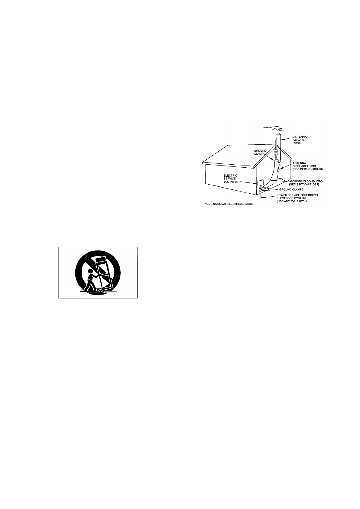
14) Outdoor Antenna Grounding — if an outside anteima or cable
system is connected to the product, be sure the antenna or cable system
is grounded so as to provide some protection against voltage surges and
built-up static charges. Article 810 of the National Electrical Code,
ANSl/NFPA 70, provides information with regard to proper grounding
of the mast and supporting structure, grounding of the lead-in wire to an
antenna discharge unit, size of grounding conductors, location of
antenna-discharge unit, connection to grounding electrodes, and
requirements for the grounding electrode.
"Note to CATV system installer:
This reminder is provided to call the CATV system installer’s attention
to Section 820-40 of the NEC which provides guidelines for proper
grounding and, in particular, specifies that the cable ground shall be
connected to the grounding system of the building, as close to the point
of cable entry as practical.
Example of Antenna Grounding as per
National Electricai Code, ANSI/NFPA 70
15) Lightning — For added protection for this product during a
lightning storm, or when it is left unattended and unused for long
periods of time, unplug it from the wall outlet and disconnect the
antenna or cable system. This will prevent damage to the product due to
lighming and power-line surges.
16) Power Lines — An outside antenna system should not be located
in the vicinity of overhead power lines or other electric light or power
circuits, or where it can fall into such power lines or circuits. When
installing an outside antenna system, extreme care should be taken to
keep from touching such power lines or circuits as contact with them
might be fatal.
17) Overloading — Do not overload wall outlets, extension cords, or
integral convenience receptacles as this can result in risk of fire or
electric shock.
18) Object and Liquid Entry — Never push objects of any kind into
this product through openings as they may touch dangerous voltage
points or short-out parts that could result in a fire or electric shock.
Never spill liquid of any kind on the product.
19) Servicing — Do not attempt to service this product yourself as
opening or removing covers may expose you to dangerous voltage or
other hazards. Refer all servicing to qualified service personnel.
20) Damage Requiring Service — Unplug this product from the
wall outlet and refer servicing to qualified service personnel under the
following conditions:
a) when the power-supply cord or plug is damaged.
b) if liquid has been spilled, or objects have fallen into the product.
c) if the product has been exposed to rain or water.
d) if the product does not operate normally by following the operating
instructions. Adjust only those controls that are covered by the
operating instructions as an improper adjustment of other controls may
result in damage and will often require extensive work by a qualified
technician to restore the product to its normal operation.
e) if the product has been dropped or damaged in any way.
f) when the product exhibits a distinct change in performance - this
indicates a need for service.
21) Replacement Parts — When replacement parts are required, be
sure the service technician has used replacement parts specified by the
manufacturer or have the same characteristics as the original part.
Unauthorized substitutions may result in fire, electric shock, or other
hazards.
22) Safety Check — Upon completion of any service or repairs to
this product, ask the service technician to perform safety checks to
determine that the product is in proper operating condition.
23) Wall or Celling Mouting — The product shoud be mounted to a
wall or ceiling only as recommended by the manufacturer.
24) Heat — The product should be situated away from heat sources
such as radiators, heat registers, stoves, or other products (including
amplifiers) that produce heat.
Page 4

Introduction
Your new TASCAM deck is a heavy-duty, portable R-
DAT recorder/reproducer designed for outdoor
recording needs in various fields from sound
reinforcement through broadcast production. Facilities
include operation using battery or AC current, backlit
LCD display, protection against accidental operations,
settings for two sampling rates when recording via the
analog inputs, S/PDIF I/O port, ID editing modes, and
others, as discussed later in this manual.
Precautions and Recommendations
Table of Contents
Important Safety Precautions
Safety Instructions....................................................... 3
Introduction
Precautions and Recommendations
Structure of DAT Cassettes......................................... 5
Subcodes
Using the Battery......................................................... 6
Hookup
Recording
Playback......................................................................11
Editing Start and Skip ID Marks
Features and Controls
Specifications
Problems and Solutions...............................................21
Block Diagram.............................................................22
Optional Accessories...................................................23
.................................................................
.....................................................................
........................................................................
....................................................................
..............................................................
......................................
.............................
.................................
..................................................
2
4
4
5
6
7
12
14
20
Environmental Conditions How to Load a DAT Cassette
This deck may be used in most areas, but to maintain
top performance and prolong operating life, observe the
following environmental limitations :
1) Nominal temperature should be 5 to 35 degrees
Celsius (41 to 95 degrees Fahrenheit).
2) Relative humidity should be 30 to 90% (non
condensing).
3) Strong magnetic fields should not exist nearby.
Beware of Condensation
When the deck is moved from a cold to a warm place or
used after a sudden temperature change, there is the
danger of condensation ; water vapor in the air could
condense on the internal mechanism, making proper
operation impossible. To prevent this, or if this occurs
(as confirmed by the indicator blinking in the LCD
display window), leave the deck for 1 or 2 hours with
the power turned on, then turn the power off before
turning it on again.
The hinged edge of the cassette must go in first, clear
window up. The cassette holder can open before powerup or while in STOP (the CHARGE/OPERATE switch
must, however, be set to OPERATE).
o* When removing cassettes, don't pull on the cassette's
slider to insure against possible damage to the
naked tape.
Page 5
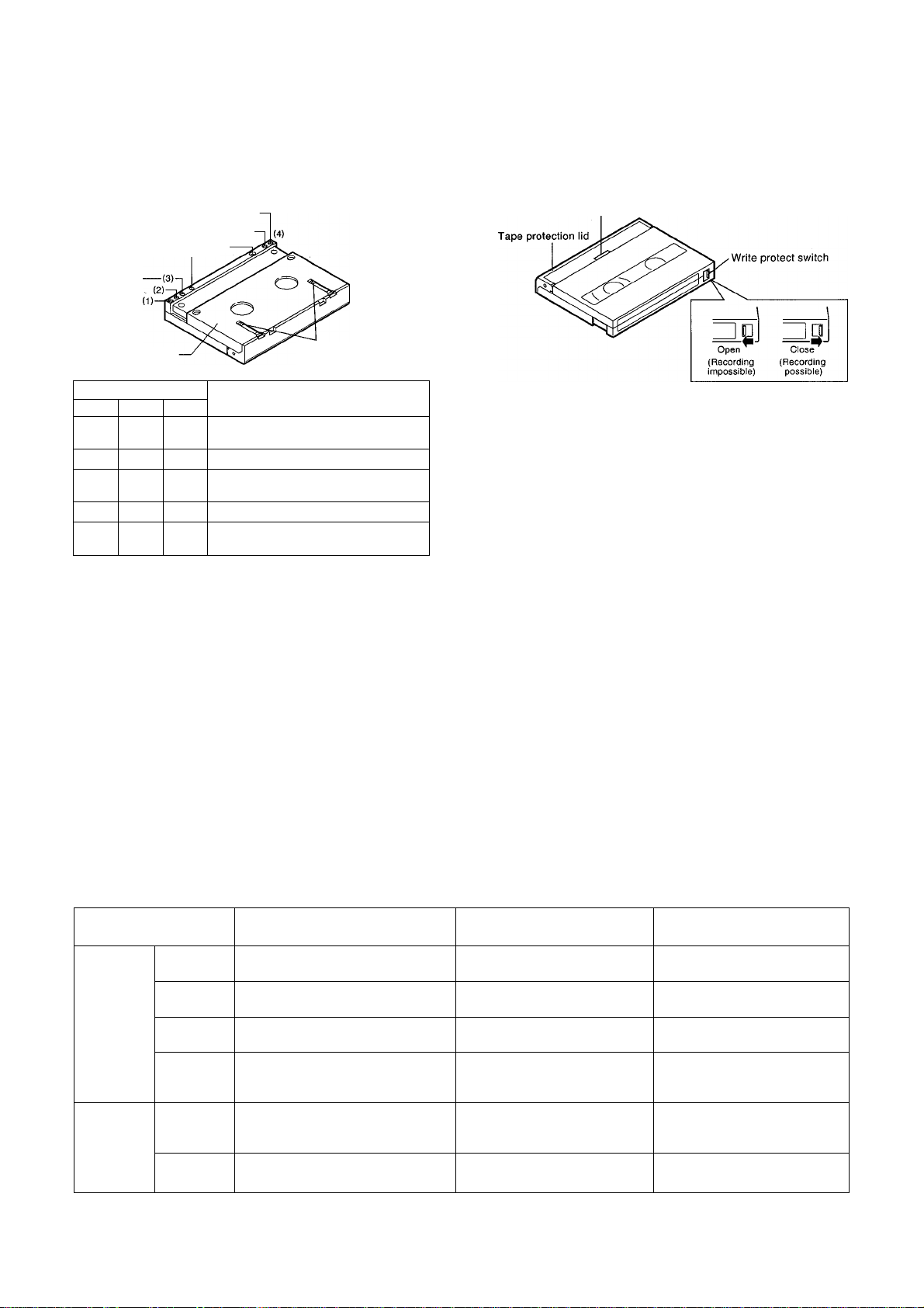
Structure of DAT Cassette
Bottom View
[—Cassette identification hole(1-4)-
Vi/rite protect hole-
Positioning hole-
sliding cover
Identification Hole
2
1
X X X
X
X X
X
o
Where: " O " = Open '' x " = Closed
3
Metal coating or equivalent/13 urn
tape thickness
X
O
O O
— —
Metal coating or equivalent/ Thin tape
o 1.5 time track pitch/13 pm tape
thickness
1.5 time track pitch/ Thin tape
(Reserved for auxiliary tape type
definitions)
Sliding cover lock
Signified
• Hole #4 shows "prerecorded" (Open) or not (Closed).
Top View
Loading grip
• Dimensions:
• Tape width:
73 X 54 X 10.5 mm (W X D X H)
3.81 mm
Notes:
Cassette shells are designed to prevent touching the
tape directly by hand.
DAT cassettes record and play in one direction only.
Do not load DAT cassettes upside down.
DAT cassettes have a tape protection lid on the front
edge to protect the tape. Do not open this lid forcibly,
and do not pull the tape out from the cassette or touch
it with your fingers.
Be sure to replace DAT cassettes in their plastic case
for storage.
Do not place DAT cassettes on a television, speaker
or near equipment which could generate a magnetic
field.
The tape used in 180-min cassettes is extremely thin
and can cause winding problems, crimping,
wrinkling, and other damage to the tape which will
destroy your work. Don't use 180-min cassettes in
this deck.
Subcodes
The following subcodes are available.
Subcode Identifies:
Start ID Beginning of each program
Index
Data
Time
Data
Skip ID Point from where tape is made
End ID End of the existing audio
Program
Number
(PNO)
Absolute
Time
(ABS)
Program
Time
to fast wind to the next Start ID
recordings
How many programs from the
beginning of the tape is the
current one
Elapsed time from the begin
ning of the tape
Elapsed time from the begin
ning of each program
Length and Location
of Data Recording
9 seconds at the beginning
of each program
1 second at the desired
point
9 seconds at the end of the
last recording
9 seconds at the beginning
of each program
Full length of the audio
recordings
9 seconds at the beginning
of each program
Note: If play starts from an intermediate point beyond the program-time recorded section, the display does not show the
elapsed time from the begining of the program.
Recorded Automatically
or Manually
Auto and Manual
Manual only
Manual only
Auto only
Auto only
Auto only
Page 6
Using the Battery
The supplied battery (and also the optional BP-Dl
battery) has been charged to 60 % of its full power at
factory. When the power drops to a point where the
battery needs to be recharged, the battery warning
indicator'!— jJ flashes in the LCD display.
o A slide knob is attached on the side of the battery.
This knob is used to show whether the battery is
"exhausted" or "charged". Therefore, the knob does
not have any direct effect on the battery performance.
CAUTION
Recharge the battery only when the battery
warning FLASHES or its service life is shortened.
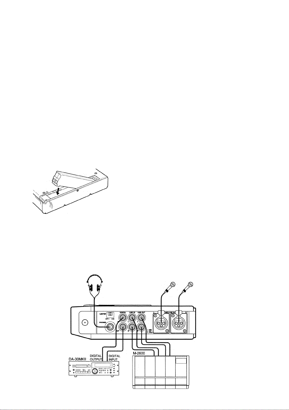
How to Load the Battery
Insert the battery, terminal side down, as illustrated.
How to Recharge the Battery
Set the CHARGE/OPERATE switch to the CHARGE
position to start charging the battery. A full charge is
achieved in about 2.5 hours.
When the battery is being charged, an LED lights red on
the PS-Dl adaptor/charger for the first 2 hours, then
turns green to indicate that you can stop charging after
about 30 minutes by removing the battery pack from the
deck. Remember, the LED does not automatically turn
off.
Insert the charged battery into the deck only when you
operate the deck using the battery. Don't leave the
battery inside the deck when operating under AC power
for long periods.
Auto Power Off When Using the Battery
The Auto Power Off feature turns off the deck if you
leave it in STOP for 6 minutes.
Hookup
WARNING
Make all connections with power off.
If you want to override this feature or prevent it from
functioning, hold down STOP and slide POWER to the
right.
Page 7

Recording
NOTE
Check to see that the write prohibit switch on the cassette you intend to record on
is NOT open.
1. If you haven't done so yet, connect your recording source to the correct inputs of
the deck and make all other necessary connections by referring to the diagram on
page 6.
2. Locate the select switch on the left side of the deck and set it to OPERATE.
3. Turn the system on.
4. Press the EJECT button. The cassette holder will open.
5. Insert the cassette into the holder.
rNPUT
ANALOG > ■ DIGITAL
MARGIN RESET
CD
6. Depending on whether your recording source is analog or digital, proceed as
follows:
Analog Source Recording
(1) Make the following switch settings :
INPUT switch to ANALOG ;
ANALOG INPUT switch to MIC, PAD 20 dB or LINE depending on source
(both the XLR and RCA inputs are active at the same time regardless of
settings of the ANALOG INPUT switch);
PHANTOM switch to ON if phantom powered mics are in use (the phantom
power remains switched off if the ANALOG INPUT switch is set to LINE);
Fs to 48 kHz for standard DAT recording or 44.1 kHz if the recording will be
used as a digital CD master recording.
(2) Press the MARGIN RESET button to see the instantaneous peak level of the
current signal. The maximum level will read "0" in the MARGIN display,
meaning that you have recorded to the maximum level allowable and there is
no headroom left. If you exceed the maximum level, the "0" will blink.
(3) Put the deck into "Input Monitor" mode by pressing RECORD (the transport
must be in STOP when you press RECORD). Then, adjust the INPUT L and R
level controls so that peaks from the source unit don't reach the OVER area in
the peak level meters.
Set the LIMITER switch (on the right side panel) to ON if the source is a mic
and is expected to have such dynamic range that you may want to decrease the
input amplifier gain.
Page 8

Digital Source Recording
INPUT
ANALOG > ■ DIGITAL
Set the INPUT select switch to DIGITAL. The deck configures itself for the
sampling rate of the incoming digital signal. The settings of the Fs switch are
overridden. 48, 44.1, and 32 will light in turn and 'DIGITAL IN" will flash in the
LCD display if a suitable digital signal is not found.
Suggestion : If you intend to make a digital copy from a DAT recorder, you can copy
subcode data (Start and Skip IDs) together with sound data by putting the deck into
AUTO ID mode. Selecting this mode is explained on the next page.
o Recording digital sources does not require any input level adjustment.
7. If you are using a new blank tape :
Press REW (regardless of the current tape position). The tape will be located to a
point 100 mm ahead of the end of the leader tape. If you don't perform this step, or
record from the middle of a blank tape, ABS time will not be recorded in the
subcode area for later reference, and the ABS display will be blank.
If you are using a tape containing some programs previously recorded:
Locate, if necessary, the blank portion of the tape by pressing F FWD. The tape
will automatically stop either at the point beyond which there is nothing recorded so
far or at an End ID mark if available. If the tape finds an End ID mark, " t'c "
shows in the left of the LCD display and "END" in the upper right. Otherwise
c noshows in the center.
©
Avoid discontinuity in the ABS time by moving the tape back the length of 2
seconds or so. This allows the deck, when going into record mode, to read the ABS
time from the previous recording and continue to record the ABS time without a
break.
8. Hold down RECORD and press PAUSE.
Automatic "Lead-in" Feature : If you are using a new blank tape, you will notice
that i- u'rnt (format) shows in the LCD display window and the RECORD LED
lights for about 10 seconds, during which a lead-in mark is automatically laid down
on the tape. While Format is displayed, do not change settings of the INPUT or Fs
select switches. Format goes out and the RECORD LED starts blinking when the
lead-in mark is fully recorded and the transport enters normal record ready mode.
As a result of automatic lead-in recording, tape playback can begin at the lead-in
mark rather than at the very beginning of the audio recording, so there is no risk of
clipping first notes.
Directly entering record mode by holding RECORD and pressing PLAY (without
passing through RECORD PAUSE mode) will also automatically record the lead-in
mark before actually starting normal audio recording. But, be aware of the
following:
Suggestion : While Format is displayed to show the lead-in mark is being
recorded, no audio can be recorded. To follow a tight audio start, first record the
lead-in mark in RECORD PAUSE instead of directly going into record mode.
Before performing step 9 (page 10), consider the following optional possibilities :
Page 9

Start ID Marking Options
Start IDs are electronic index marks in the subcode area of the tape that make it easy to
find the start of each selection on the tape. You can make Start ID marks during the
initial audio recording, or add them to the recording later. Consider the following
possibilities before actually initiating audio recording :
AUTO ID Mode
CZD
-Start IDs-
r
y
1 /
There must be more
than 9 seconds.
—■»I AUTO i5~l~-
AUTO ID Level
MARGIN RESET ID SELECT
I
1 \''
CD
WA /
In this mode, Start ID and program number will automatically be recorded at each
occurrence of audio level exceeding -48 dB or user selected decibels (discussed
below) after a lapse of about 3 second lower levels or silence. (The first Start ID and
program number after the deck is put into record mode are recorded when sounds
exceeding a selected level are fed into the deck, regardless of the length of preceding
lower signals or silence.) To put the deck into AUTO ID mode, press the ID SELECT
switch to have "AUTO ID" light up in the display window.
Note that a quiet passage ("pianissimo") might cause the beginning of the next passage
to be indexed and numbered as if it were a new program. Don't worry. You can correct
it (with "Erase Start") later.
Restriction : No Start ID is automatically recorded unless there is more than 9
seconds since the previous Start ID.
The sensitivity of the AUTO ID circuit defaults to -48 dB but can be set to -42, -54,
-60 or -66 dB. To change the sensitivity level:
(1) When no ID editing mode is selected, hold down MARGIN RESET and press ID
SELECT. The current sensitivity level will blink in the left of the display window.
(2) Press MARGIN RESET until the desired level shows.
Manual Start ID Writing
(3) Press ID SELECT to make the setting effective.
O’ The setting is switched back to -48 dB when turning off the deck.
You can manually index the beginning of each program. Program time is automatically
recorded together with Start IDs.
o There must be 9 seconds or more between two Start ID marks for the correct search
function.
To enter Manual Start ID Writing mode :
Press ID SELECT until "WRT START" shows in the right of the LCD display.
A Start ID is laid down on tape when you hit RECORD after putting the deck into
record. (You can also hit RECORD during play too.)
A Start ID recording lasts about 9 seconds and is noted by "WRT START" flashing in
the right of the display.
IT#- While a Start ID is being written, all transport buttons except for STOP are
disabled.
Before starting audio recording, consider the possibility of recording Skip and End ID
marks. See below for an explanation.
9
Page 10

9. To start audio recording (analog or digital), press PLAY or PAUSE.
If you have selected "AUTO ID," the instant the first note of the music is actually
fed to the tape, recording of the following starts at the same time :
o Start ID mark
o Program number (when the tape starts from its beginning or the previous PGM
number is read)
o Program time
These three data items are recorded for 9 seconds each time a new audio recording
is made.
Whether or not AUTO ID is selected, the point on the tape where the transport
goes into record is automatically marked for later autolocation. It will be the same
for the point where the transport exits record mode. Each time audio recording is
made, the previous record-in and out marks are erased from memory and the new
points are marked. Autolocating to those points is explained in the section on
playback.
o To interrupt audio recording temporarily, press PAUSE. A subsequent pressing
of PLAY or PAUSE will resume the recording.
o To definitely end recording, press STOP. You may want to end recording by
marking the point with an End ID as explained below.
Recording Skip ID
Marks
(ZD
Recording an End iD Mark
You can either enter Skip ID marks during the initial audio recording or they can be
added to the recording during play.
If you want to enter a Skip ID while audio recording is taking place, proceed as
follows:
(1) Press the ID SELECT switch as many times as necessary to have "WRT SKIP"
light in the LCD display.
(2) At the desired moment during record, hit RECORD. "WRT SKIP" will blink for 1
second, during which a Skip ID mark is recorded on the tape.
CAUTION
Don't write an End ID mark at an intermediate point of the existing audio
recordings, which invalidates all the recordings that follow the End ID mark. For
example. If your tape contains 10 programs and you re-record program #3 and
terminate it by writing an End ID mark, then the tape will not run past that point
and you cannot access programs #4-10 unless you erase that End ID mark by re
recording program #4.
(1) Press the ID SELECT switch until "WRT END" lights in the LCD display.
10
(2) When reaching the end of audio recording, hold down RECORD until "WRT END"
blinks, indicating an End ID mark starts being recorded.
After 9 seconds, the indication will go out and the tape will automatically rewind,
stopping at a point 2 seconds lower than the End ID mark recorded. This
intentional overshoot ensures that the current End ID mark is fully erased, and that
the deck continues to record ABS time without a break when you add a new audio
recording to the end of the existing ones.
Page 11

Playback
This deck is not capable of playing back recordings externally made at a 32 kHz
sampling rate and in Long Play mode.
CAUTION
Avoid damaging your ears by turning the PHONES volume fully down before
putting on the headphones.
1. Check to see that all connections are correctly made.
2. Check to see that the OPERATE/CHARGE select switch is set to OPERATE on the
left side panel.
3. Turn the system on.
4. Press EJECT. The cassette holder will open.
5. Insert the cassette in the holder. Notice that a cassette icon flashes in the LCD
display to indicate that the tape is being loaded.
Autolocation
Autolocating to user
marked points
►
njur
6. If you want the tape to skip to the next Start ID mark when it finds a Skip ID mark,
press the ID SELECT switch to have "AUTO ID" light up on the display.
7. Press PLAY to have the tape start playing.
o To interrupt play, press PAUSE. To resume play, press PLAY or PAUSE,
o To definitely stop play, press STOP.
Suggestion : Pressing PLAY during the autolocate process causes the tape
automatically to start playing at the end of the autolocation. If you want the deck to go
into Pause mode, you can press PAUSE instead of PLAY.
You can mark any point on the tape to which you want to autolocate, as follows ;
Switch the time counter in the center of the LCD display to show ABS time with the
COUNTER MODE switch, and when playback reaches the desired point, press the
RESET button.
To autolocate to the mark, hold down STOP when the transport is in Stop and press
PLAY. " L c " will appear in the left of the LCD display, the center time counter
displaying the time address the tape is being located to.
inr The time counter shows a broken line if there is no mark stored in memory.
ITT Each time you mark a point on the tape, the previous one is erased.
11
Page 12

Autolocating to the
record-in or out points
Choosing Selections
© ®
As stated earlier in the section on recording, the points on the tape where the deck
went into, and out of record mode most recently has been stored in memory
automatically.
To autolocate to the record-in point, hold down STOP and press REW when the
transport is in Stop and the time counter is in its ABS mode. " in" will show in the
left of the LCD display and the time counter will read out the time address the tape is
being located to. Actually, the tape is located to the point plus a 2-second preroll time.
To autolocate to the record-out point, hold STOP and press F FWD when the transport
is in Stop and the time counter is in its ABS mode. " at " will show in the left of the
LCD display and the time counter will show the time address the tape is being located
to. Actually, the tape is located to the point plus a 2-second preroll time.
O’ As with the user marked autolocation point, if there is no record-in or out marks in
memory, the time counter shows a broken line.
To advance to the next selection, press the forward SKIP button. The tape will fast-
forward to the next Start ID mark and stop. If PLAY is pressed before or after SKIP, the
tape automatically plays from that point on. You may press the forward or reverse
SKIP button a number of times to skip over several selections.
If you want the deck to go into pause at the end of skip functions, press PAUSE before
or after SKIP.
Editing Start and Skip iD Marks
o When Start IDs are added or erased, program numbers on tape get out of
order. Be sure to restore program numbers to proper sequence by going
through the RENUMBER operation (discussed below).
o No Skip ID can be recorded where a Start ID mark exists.
Recording Start/Skip ID
Marks
You can enter Start and Skip ID marks only when the tape is playing.
1. Press the ID SELECT switch until "WRT START” or "WRT SKIP” lights in the
LCD display.
IMPORTANT
12
2. Play the tape to locate to the point where you want to enter a Start or Skip ID mark,
and press RECORD.
Page 13

"WRT START" or "WRT SKIP" will flash to indicate that the corresponding mark
is being recorded. The Start ID mark is recorded for 9 seconds, and the Skip ID
mark is recorded for 1 second. Entering a Start ID requires that the current location
is more than 9 seconds (in terms of ABS time) apart from the previous Start ID
mark (if available).
O’ While a Start or Skip ID mark is being recorded, all the transport controls are
disabled except for STOP.
Erasing Start/Skip ID Marks
Renumbering
\ I /
-~RENUM-<~
You can erase Start or Skip ID marks when the transport is in STOP, PLAY or PLAY
PAUSE.
o Erasing Start or Skip ID marks does not affect any audio data recorded on tape.
1. Press the ID SELECT switch until 'ERASE START " or "ERASE SKIP" lights in
the LCD display.
2. Press RECORD. The tape will rewind back to the beginning of the previous Start or
Skip ID mark, and will automatically start running at normal play speed (program
material muted) to erase the mark encountered, as confirmed by "ERASE START"
or "ERASE SKIP" flashing.
When erasing is complete, program material is unmuted. The tape continues to run
at normal play speed.
When adding or erasing Start ID marks, the program numbers on tape get out of order.
All programs then need to be "renumbered" in order, as follows :
1. When the transport is in PLAY, PLAY PAUSE or STOP, press the ID SELECT
N
switch until "RENUM" lights in the LCD display.
2 Press RECORD.
The tape will rewind to its beginning, and the renumbering process will start, as
confirmed by the RENUM indicator flashing.
13
Page 14

Features and Controls
Left Side Pane!
1. DC IN connector
For connection to the provided PS-Dl adaptor only.
2. OPERATE/CHARGE select switch
Set to OPERATE for the deck to be operated (using
AC current or battery), or CHARGE for charging the
battery.
NOTE
If this switch is NOT set to OPERATE, all other
switches and buttons cannot operate.
11 12 13 14
Top Pane!
3. POWER switch
Slide to the right to switch on power to the deck.
If you do so while holding down STOP (when the
deck is battery powered), the Auto Power Off feature
(p.6) is defeated.
4. Cassette holder
For loading DAT cassettes only. Conventional audio
cassettes are not accepted.
5. EJECT button
Press to open the cassette holder. Effective only when
the CHARGE/OPERATE switch is set to OPERATE
and the transport is in STOP or the deck is turned off.
When pressing EJECT, the tape counter (shown or
hidden) is reset to 0000 and the MARGIN reading is
cleared.
6. ANALOG INPUT switch
When using inputs to the MIC/LINE IN XLR
connectors, set to MIC if the source is a mic or PAD
20 dB to attenuate the mic inputs, or set to LINE for
recording from line level sources.
7. PHANTOM (+48V) switch
Set to ON when using phantom powered mics. When
setting the ANALOG INPUT switch to LINE, the
phantom power is automatically switched off.
14
Page 15

WARNINGS
The PHANTOM switch must be OFF when no
phantom powered mics are used.
Don't operate the PHANTOM switch when
recording is taking place or while in Input Monitor
mode.
After skip has started, you can change the number of
programs to skip over. For example, if you press the
right SKIP button, say 5 times running, and then the
left SKIP button once, you'll skip to the fourth
program ahead, instead of the fifth.
11. REW button
If pressed when in STOP or running in F FWD,
winds the tape at high speed in reverse.
"MICROPHONE CABLES AND MICROPHONES
CONNECTION: TO PREVENT HAZARD OR
DAMAGE, ENSURE THAT ONLY MICROPHONE
CABLES AND MICROPHONES DESIGNED TO
THE lEC 268-15A STANDARD ARE
CONNECTED."
"CONNEXIONS DES MICROPHONES ET DE
LEURS CABLES: POUR EVITER TOUT
ENDOMMAGEMENT, S'ASSURER DE BRAN
CHER UNIQUEMENT DES MICROPHONES ET
DES CABLES DE MICROPHONES CONÇUS
SELON LA NORME IEC 268-15A."
8. Fs select switch
This selects the sampling rate that will be used for
recording analog inputs only.
Set to 44.1 kHz if the tape will be used as a digital
master for CD production, or 48 kHz if the tape will
be used for other applications.
This switch has no effect when recording from digital
inputs or during playback. In these cases, the deck
will automatically switch to the frequency at which
those sources were originally recorded, as indicated
by 48, 44.1 or 32 in the upper right corner of the
display window.
If pressed once during play, offers 3 times normal
speed reverse cueing for review. If pressed twice,
offers 9 times normal speed reverse cueing. A third
press, switches back to 3 times normal speed reverse
cueing.
Holding down the button (for 1 second or more)
during play also allows cueing to an earlier point.
Review starts from the point where you release the
button.
A tap on REW during forward cueing (activated
with F FWD in a similar way to activating reverse
cueing) switches to the same speed reverse cueing ;
inversely, a tap on F FWD during reverse cueing
switches to the same speed forward cueing.
Another function is to autolocate the tape to a
record-in point. See the section on playback for an
explanation.
12. F FWD button
Similar to REW, but winds the tape in the forward
direction, offers the forward cueing, or autolocates
to a record-out point.
It is also used to autolocate the tape either to the
point beyond which there is nothing recorded so far
or to an End ID marked point. The tape will move
back over the length of 2 seconds when it finds an
End ID mark.
9. INPUT select switch
Set to ANALOG when recording from the analog
XLR balanced inputs or RCA unbalanced inputs, or
DIGITAL when recording from DIGITAL IN.
"48," "44.1," and "32" will light in turn in the upper
right corner of the display window and "DIGITAL
IN" will flash in the center if, when recording from
digital sources, a suitable digital signal is not found.
10.SKIP buttons
Effective in PLAY, PAUSE, and STOP. When
pressed once, the left button rewinds the tape to the
beginning of the current program. Press the button
repeatedly to skip over several programs. The right
button fast-forwards the tape to the beginning of the
next program.
The deck automatically starts playing or goes into
pause mode at the end of search functions if you
press PLAY or PAUSE before or after SKIP.
13.STOP button
Stops any tape motion. It also stops the DAT head
drum from spinning against the tape.
It is also used to disable Input Monitor mode.
14.PLAY button
If pressed while in STOP, REW or F FWD, starts
tape playback.
If pressed after PAUSE, resumes playback from the
point of interruption.
If pressed while in record ready (RECORD PAUSE),
starts recording.
If pressed before or after SKIP, starts playback at the
end of search functions.
It is also used to have the tape automatically start
playing after completing autolocation.
15
Page 16

15 16
17
K
Front Panei
15.PAUSE button
If pressed during record or play, temporarily stops
the tape. Pressing PAUSE or PLAY resumes record
or play accordingly.
If pressed while in STOP, activates Play Ready
mode ; then press PAUSE or PLAY to start
playback.
If pressed while holding down RECORD, activates
Record Ready mode ; then press PAUSE or PLAY to
start recording.
If pressed before or after SKIP, puts the deck into
pause mode at the end of search functions.
It is also used to have the deck go into pause mode
after completing autolocation.
NOTES
o If you interrupt Record by pressing PAUSE and
ieave the deck in that status, the deck wili
automaticaiiy go into "input Monitor" mode after
5 minutes.
o If you interrupt Piay by pressing PAUSE and
ieave the deck in that status, then the deck wiil
go into STOP after 5 minutes.
16. RECORD button
Pressing PLAY while holding down RECORD starts
recording. You may first want to go into Record
Ready mode by pressing PAUSE while holding
down RECORD.
The associated LED blinks during Record Ready
mode. It glows solid and the ► indicator lights in
the LCD display window when recording starts.The
LED also lights when "Input Monitor" mode is
entered by pressing RECORD when the transport is
in STOP.
Difference between the Record Ready and the
Input Monitor Mode : Record Ready is a mode
accessible by holding RECORD and pressing
PAUSE. The head drum is in motion in this mode.
After 5 minutes, the mode is automatically
cancelled.
Input Monitor mode is entered by pressing
RECORD in STOP. The drum is not in motion. To
leave the Input Monitor mode, press STOP. The
Input Monitor mode can be entered even when no
cassette is inserted into the deck. In this case, the
RECORD LED does not light. Depending on
whether the input signal is analog or digital, "A-dA" or "d-A" will show in the display.
The proper recording levels can be set in either
Record Ready or Input Monitor modes.
NOTE
The Input Monitor mode cannot be entered if the
tape is write protected.
17.INPUT level controls
The center knob adjusts the recording level of the
left input, and the outer ring adjusts the recording
level of the right input. Valid only for the record
level of analog inputs.
When you turn the outer control, the inner control
also turns. To turn the outer control only, hold the
inner control.
16
Page 17

18.PH0NES control
Adjusts the listening level of the headphones
plugged into the PHONES jack on the right side
panel.
CAUTION
Avoid damaging your ears by fully turning down
the PHONES control before putting on the
headphones. To hear sounds, turn the control up
slowly.
PGM : Indicates the elapsed time from the start of
the program currently being played back. The deck
will calculate elapsed time since the previous Start
ID. A broken line will show if the tape is inserted
in-between Start IDs.
REMAIN : Indicates the remaining time on the tape.
When a prerecorded music tape (encoded with
"TOC") is being played back, the reading is to
second accuracy. If the tape is not recorded with
TOC, the seconds column will be blank.
19. LCD (Liquid Crystai Display)
This backlit display (see also #24) provides you with
a variety of information, keeping you aware of what
is currently taking place.
DIGITAL IN : Lights when the INPUT select switch
is set to DIGITAL. Blinks when suitable digital
signals are not fed into the deck.
AUTO ID : Lights when AUTO ID mode (p.9) is
selected. This mode is also used to have the tape
skip to the next Start ID mark when a Skip ID mark
is encountered during play.
lOOl : Blinks when a tape is being loaded. Glows
solid when loading is complete. It does not appear
when there is no tape inside the deck.
[5 : Blinks when condensation occurs in the deck.
<ii3
: This is a battery meter with its 3 segments
representing a scale. As the battery power goes low,
the segments turn off in sequence, and then the last,
right segment starts blinking to warn you that the
battery would fully run down in about 10 minutes of
continuous record.
CAUTION
To maximize the service life of the battery, avoid
recharging the battery before the battery warning
starts blinking.
► '• : Rewind, fast forward, play, and
pause are indicated by the corresponding marks
being lit.
PGM NO : Shows the current program number. Also
displayed is the current sensitivity level of the
AUTO ID circuit when selecting "AUTO ID" with
the ID SELECT switch.
ABS : Indicates the elapsed time from the beginning
of the tape up to the current position. If a broken line
shows in the ABS display mode, the tape was not
recorded with ABS time data.
A broken line is displayed when the deck is
calculating the remaining time on the tape.
Tape Counter (when neither ABS nor PGM nor
REMAIN shows, as selected with the COUNTER
MODE switch) : Indicates the distance the tape has
travelled from a zero reference point established
with the RESET button.
Peak Level Meters : These register input levels
during Record Ready, Input Monitor (see #16) or
Record modes and, output levels during Play.
48, 44.1, 32, and 32LP : In analog recording, 48 or
44.1 will light, as selected by the Fs switch. In
digital recording, 48, 44.1, or 32 will light
depending on incoming signals. 48, 44.1 and 32 will
light in turn and DIGITAL IN will blink if suitable
digital signals are not fed into the deck.
32LP will blink to indicate that the tape cannot be
played back with this deck because it is originally
recorded at the sampling rate of 32 kHz and in Long
Play mode.
(ID Mode indications) : This section of the display
shows the current ID editing mode, as selected by
the ID SELECT switch. A blinking indicator shows
the corresponding ID mark is being written on tape
or erased or programs are being renumbered. Each
time an ID mark is read off tape, the corresponding
indicator lights steadily.
MARGIN : This is a digital peak-hold meter,
showing the available headroom before digital
saturation is reached and distortion occurs. It holds
the highest reading since MARGIN RESET was last
pressed (the reading is also reset when EJECT is
pressed). It ranges between 39 and 0 dB during
recording. If 0 dB is flashing, it indicates that the
meter reached the OVERload point. The OVER
indication cannot appear while in playback.
17
Page 18

20 21
20. COUNTER MODE switch
Each time this switch is pressed, the following
information shows in sequence in the center of the
display window.
1. ABS (absolute) time : elapsed time'from the
beginning of the tape
2. PGM (program) time : elapsed time from the
beginning of each program
3. REMAIN time : remaining time on the tape
4. Distance the tape has travelled frdm a zero
reference point
5. TOC (if available) : total number of programs on
the tape and total play time
To select the TOC mode,.you have to let the tape
play for several seconds in advance after inserting it
into the deck.
After a 3-second TOC reading, the display will
automatieally be switched back to show the ABS
time.
21. RESET button
Establishes a new zero reference point. This button
has effect only when the display is switehed to Tape
Counter mode, as selected with the COUNTER
MODE switch.
22.MARGIN RESET button
Defeats a MARGIN (headroom available)
indication so new readings can be taken.
23.ID SELECT switch
Each time this switch is pressed the following ID
editing modes are selected in sequence, as indicated
by the display. The modes that can be entered differ
depending on the current transport modes as shown :
RECORD or RECORD PAUSE
Blank (ID mode off)
AUTO ID
WRT START
WRT SKIP
WRT END
Other modes
Blank (ID mode off)
AUTO ID
WRT START
WRT SKIP
ERASE START
ERASE SKIP
RENUM
After the display indicates the desired ID editing
mode, pressing the RECORD button will actually
execute the ID mode selected. See also the section
on editing ID marks.
NOTE
EJECT also clears the tape counter to 0000 (shown
or hidden).
Another function is to mark a point to which you
want to autolocate, as discussed in the section on
playback.
18
The ID SELECT switch cannot operate if the
cassette is write protected.
Page 19
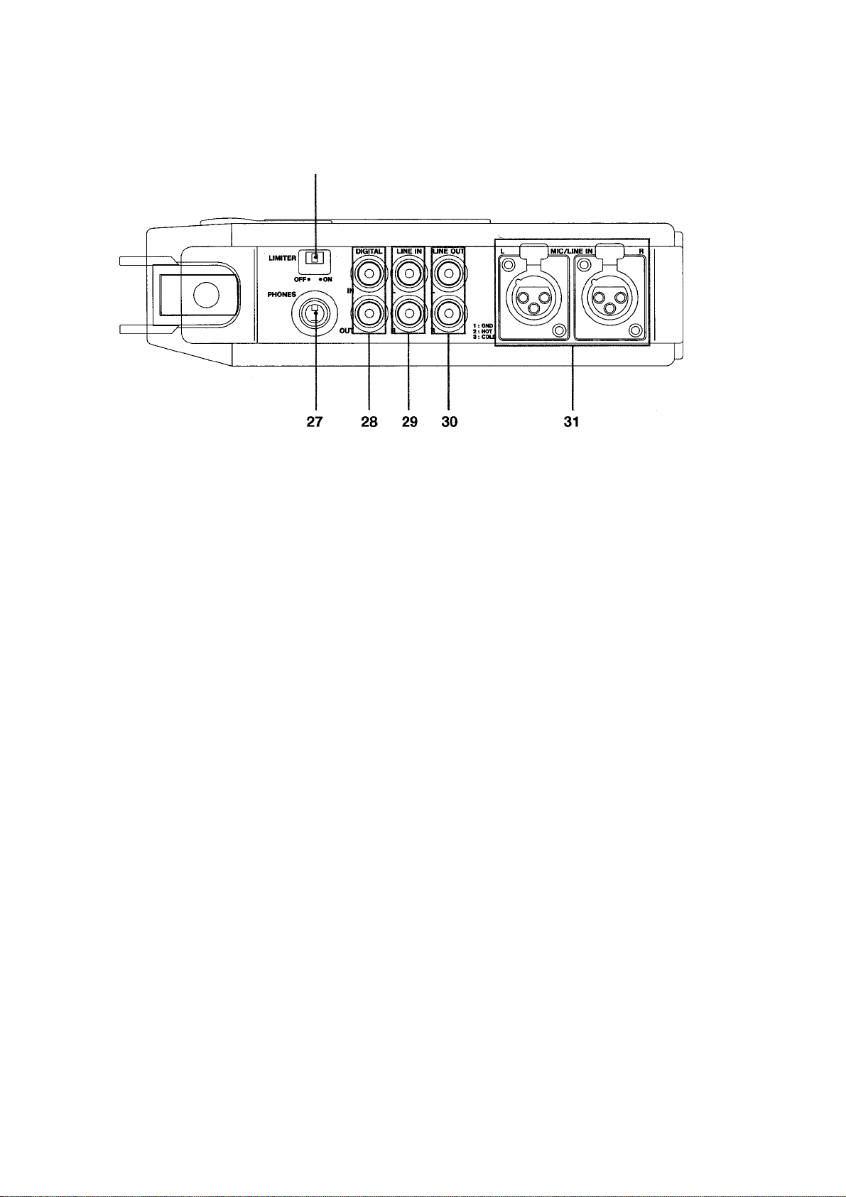
26
Right Side Panel
24. LIGHT switch
Used when the deck is battery powered. Press to
back light the LCD display. The light will
automatically turn off at the end of 10 seconds.
When the display is backlit, if you press LIGHT
once more, the display will be turned off.
The display is automatically backlit when the deck is
powered from the AC outlet. You can turn off the
light by pressing LIGHT.
25. HOLD switch
If slid to the right, locks all the push buttons (except
for COUNTER MODE, RESET, and MARGIN
RESET) to their current positions and prevents them
from being accidentally operated. If you attempt to
operate a button and it is disabled, "Hoi cl" appears
in the LCD display window to remind you that you
must first slide the switch back to the left.
26. LIMITER switch
Set to ON so a built-in limiter prevents the signal
level from exceeding 0 dB when recording from
mics (with ANALOG INPUT set to MIC or PAD).
27. PHONES jack
For connection to stereo headphones only. Don't use
2 conductor mono headphones with this jack.
28. DIGITAL IN and OUT connectors
These RCA IN/OUT jacks are for connection to the
S/PDIF (lEC 958 TYPE II) digital I/O ports of
external digital equipment through a 75 ohm coaxial
cable.
29. LINE IN connectors
These RCA jacks are for plugging unbalanced
analog sources into the deck.
When these connectors are in use, be sure to set the
ANALOG INPUT switch to its LINE position for
optimum S/N performance.
30. LINE OUT connectors
For connection to the unbalanced analog signal
inputs of external equipment.
31. MIC/LINE IN connectors
These balanced XLR type connectors accept
balanced analog sources. Pin 1 is GND, Pin 2 is
HOT, and Pin 3 is COLD.
19
Page 20

Specifications
Format: Rotary head digital audio tape deck
Record Time : 120 minutes (with 120-min tape)
Fast Winding Time : Approx. 60 seconds
Tape Speed : 8.15 mm/sec. (12.225 mm/sec. during
play)
Quantization : 16-bit linear
Error Correction Method : Octuple error correction
Drum Speed : 2,000 rpm
Sampling Rates:
48 kHz recording (digital/analog), play
44.1 kHz recording (digital/analog), play
32 kHz recording (digital only), play
Channel: 2 channels
Frequency Response : 20 Hz to 20 kHz, ± 0.5 dB
(44.1/48 kHz) (LINE)
S/N : Better than 90 dB (LINE)
Dynamic Range : Better than 90 dB (LINE)
Total Harmonic Distortion : Better than 0.007%, 1 kHz
(LINE)
Channel Separation : Better than 85 dB (1 kHz)
Wow and Flutter : Unmeasurable (less than ±0.001%)
Analog I/O
MIC/LINE IN (XLR-3-31 x 2)
MIC
Nominal level: -60 dBm (0.8 mV)
PAD : 20 dB
Input impedance : 2.5 kohms, balanced
LINE
Nominal level: +4 dBm (1.2 V)
Input impedance : 10 kohms, balanced
LINE IN (RCA X 2)
Nominal level: -10 dBv (0.3 V)
Input impedance : 35 kohms, unbalanced
LINE OUT (RCA x2) :
Nominal level: -10 dBv (0.3 V)(10-kohm load)
Output impedance : 500 ohms, unbalanced
PHONES (1/4" jack x 1)
Max. output level: 15 mW -i-15 mW (32 ohms)
Digital I/O
IN (RCA X 1): lEC 958 TYPE II (S/PDIF)
OUT (RCA X 1): lEC 958 TYPE II (S/PDIF)
Power Supply : 2-way (AC adaptor PS-Dl and Ni-Cd
battery BP-Dl (7.2 V, 1.4 Ah))
U.S.A./Canada : 120 VAC, 60 Hz
Europe : 230 VAC, 50 Hz
U.K./Australia : 240 VAC, 50 Hz
Power Consumption :
13W (with PS-Dl, during OPERATE)
15W (with PS-Dl, during CHARGE)
Battery Charging Time : Within approx. 2.5 hours
Battery Life : Approx. 120 minutes (continuous
recording, PHANTOM OFF), approx. 100 minutes
(continuous recording, PHANTOM ON, (2 mA x
2)), Approx. 180 minutes (stop)
Dimensions (WxHxD): 258 x 54 x 188 mm (10-3/16" x
2-1/8" X 7-3/8")
Weight : 1.2 kg (2-10/16 lbs) (excluding battery
(240 g))
Supplied Accessories : AC adaptor/battery charger
(PS-Dl), Ni-Cd battery (BP-Dl), and Carrying belt
o In these specifications, 0 dBv is referenced to I Volt,
and 0 dBm is referenced to 0.775 Vrms. Actual
voltage levels are also given in parenthesis (0.316 V
for -10 dBv rounded off to 0.3 V).
o Changes in specifications and features may be made
without notice or obligation.
DA-PI External Dimensions
20
Page 21

Problems and Solutions
Problem Probable Causes
No power
Controls not operable
ID SELECT switch not operable
1. AC adaptor unplugged.
2. Battery not charged.
3. CHARGE/OPERATE switch set to
CHARGE.
1. HOLD switch engaged.
2. Condensation.
Write protect switch open. Close write protect switch.
Recording impossible Write protect switch open.
Mies not operable 1. Incorrect ANALOG INPUT selector
setting.
2. Phantom mics in use, but PHANTOM
switch not engaged.
Start ID marking not automated
1. AUTO ID mode not selected.
during audio record
2. Improper sensitivity level setting.
Cannot record ABS time
Cannot monitor digitai inputs
Battery warning blinks although
Audio record started from an intermediate
point.
Incorrect connection of digital sources.
1. Memory effect.
the battery has been fully charged
shortly before.
2. Service life of the battery ended.
Shortly after the battery starts
charging, the red LED on the
adaptor/charger turns green.
LED on the adaptor/charger
doesn't light after starting
1. Incorrect insertion of the battery pack.
2. Overdischarged.
charging battery.
Cannot enter Input Monitor mode.
Deck under battery power
automatically turned off.
Tape cannot stop immediately after
pressing STOP.
No playback sounds
An ID editing mode is selected.
1. Battery has run down.
2. Deck left in STOP for 6 minutes.
ID mark-related functions (write, erase, etc)
in progress.
1. Heads are dirty.
2. Programs recorded at 32 kHz in
Long Play mode.
Solution
1. Plug in AC adaptor.
2. Recharge battery.
3. Set switch to OPERATE.
1. Disengage switch.
2. Wait for 1 or 2 hours.
Close write protect switch.
1. Correct setting.
2. Engage switch.
1. Press ID SELECT to have AUTO
ID light up.
2. Correct setting (p.9)
Before starting audio record, rewind the
tape to the beginning or a point where
ABS time is previously recorded.
Correct connection.
1. Fully discharge the battery by leaving
the deck in STOP before recharging.
2. Replace with a new battery pack.
1. Insert the battery pack correctly.
2. Continue to charge. LED will light red
after a while.
Disable the mode with ID SELECT.
1. Recharge battery.
2. Switch on power again (p.6).
Wait for a while.
1. Clean heads with commercially
available head cleaning tape.
2. This deck is not capable of playing
these programs.
Error Messages
Display
" 5]" blinking Condensation
" i_ Jj" blinking Battery needs charging.
"DIGITAL IN" blinking Suitable digital signals are not found.
11 » / » /11
• IL IL L I
You attempted to operate disabled
buttons.
Problem
Solution
Wait for 1 hour or 2 before using the deck.
Charge battery. (About 10 minutes of continuous
record can be made after the warning starts blinking).
Check connection.
Slide HOLD switch to the left to release
the function.
21
Page 22

Block Diagram
For U.S.A.------------------------------------------------------------------------------------------------------
TO THE USER
This equipment has been tested and found to comply with the limits for a Class A digital device, pursuant
to Part 15 of the FCC Rules. These limits are designed to provide reasonable protection against harmful
interference when the equipment is operated in a commercial environment. This equipment generates,
uses, and can radiate radio frequency energy and, if not installed and used in accordance with the
instruction manual, may cause harmful interference to radio communications.
Operation of this equipment in a residential area is likely to cause harmful interference in which case the
user will be required to correct the interference at his own expense.
CAUTION:
Changes or modifications to this equipment not expressly approved by TEAC CORPORATION for compliance
could void the user's authority to operate this equipment.
22
Page 23

Optional Accessories
CS-D1 Carrying Case
BP-D1 Ni-Cd Rechargeable Battery Pack
CB-D1 Battery Charge Box
23
Page 24

TASCAM
TEAC Professional Division
DA-P1
TEAC CORPORATION 3-7-3, Nakacho, Musashino-shi, Tokyo 180, Japan Phone: (0422) 52-5081
TEAC AMERICA, INC. 7733 Telegraph Road, Montebello, California 90640 Phone: (213) 726-0303
TEAC CANADA LTD. 340 Brunei Road, Mississauga, Ontario L4Z 2C2, Canada Phone: 905-890-8008
TEAC UK LIMITED 5 Marlin House, Marlins Meadow, The Croxley Centre, Watford, Herts. WD1 8YA, U.K. Phone: 01923-819699
TEAC DEUTSCHLAND GmbH Bahnstrasse 12, 65205 Wiesbaden-Erbenheim, Germany Phone: 0611-71580
TEAC FRANCE S.A. 17, Rue Alexis-de-Tocqueville, CE 005 92182 Antony Cedex, France Phone: (1) 42.37.01.02
TEAC NEDERLAND BV Perkinsbaan 11,3439 ND Nieuwegein, Nederland Phone: 03-402-30229
TEAC AUSTRALIA PTY., LTD.
A.C.N. 005 408 462
TEAC ITALIANA S.p.A. Via C. Canto 5, 20092 Cinisello Balsamo, Milano, Italy Phone: 02-66010500
106 Bay Street, Port Melbourne, Victoria 3207, Australia Phone: (03) 646-1733
PRINTED IN JAPAN 0998U2.2 M-1072P
 Loading...