

Page 1
TASCAM
TEAC Professional Division
DA-88
Digital Multitrack Recorder
OWNER’S MANUAL
5700141001
Page 2
Introduction
The TASCAM DA-88 is a digital audio multitrack recorder
designed for wz in a variety of professional applications. It
records 8 channels of digital audio data on a readily available
standard Hi8 video cassette tape. which is comparable in
handiness and compacmw to conventional analog audio
cass.sne tapes. Other feamres of the DA-88 include the
following :
0 Newly developed TASCAM-exclusive high performance/
high wear resis+x. rotary 4-head mechanism with
TASCAM original nack layout.
0 Synchronization of up to 16 DA-88s for a setup of 128
tracks simply by connecting them in series, without
having to “sa any synchronizer-controller.
o Synchronization with video or other audio recorders
(analog or digital) under SMF’lWEBU time code conWo1
when the optional SY-88 Sync Board is installed.
o Analog inputs and outputs handled by both RCA jacks
(unbalanced) and 25-pin D-sub conn~cmrs (balanced), and
digital inputs and outputs by a 25-pin serial I/O port.
o CD quality sound ensured by 16.bit linear quamizadon
and 48/44.1 kHz sampling rate.
o Auto punch-in/out with rehearsal capability
o 2-point au~olocavx
o Variable speed playback (up to 6.0% in 0.1 % steps)
Backup Feature
The following are retained in a backup memory each time
the pcw.z is mmed off (battery life is about 50,000 hours) :
0 MEMO 1 and 2 points
0 Pitch change
o Offset time
0 Track delay time
o Crossfade time
o F’unch-in and owpoints
0 Preroll time.
0 DIGITAL IN on/off
0 Monitor selecdon (ALL INPUT, AUTO INPUT and
INSERT)
o CHASE on/off
0 CLOCK selecdon
TABLE OF CONTENTS
Important Safety Precautions.. ................................. 2
Safety Instructions.. ............................................... .3
Introduction.. .................................................... <. .. .4
Precautions and Recommendations ........................ .5
Specifications.. ...................................................... 6
Optional Accessories.. ........................................... .C
Features and Controls.. ...................................... I-12
Front Panel.. ........................................................ 8
Rear Panel.. ........................................................ .l 1
Note for U.K. Customers.. ...................................... .12
Hookup.. .............................................................. .13
Formatting a Tape.. ........................................... 13.14
Audio Record and Playback.. ............................. 15-21
Initial Recording.. ................................................ .14
Punch-in (Insert) Recording ................................... .16
Bouncing Tracks (Ping-pang). ................................ .20
Entering a Track Delay Time.. ............................... .21
Variable Speed Playback.. ..................................... .21
Autolocation Controls.. .................................... .22-23
Seuing Locating Points.. ...................................... .22
Repeat Play.. ...................................................... .22
Multiple-DA-68 System ..................................... .23-25
Synchronization.. ................................................ .23
Entering an Offset.. .............................................. .24
Digital Dubbing.. ................................................ .25
Error Messages.. .................................................. .26
0 Using this manual
1~~ Before acmallv usim? the DA-88, please read this
manual thoroughly at least once, so you will know
where to r&urn when yo” need a”swers. Even though
~nswz that misunderstandings won’t slow you down.
Use of capital letters : In general, w w all appw case
type to designate a particular switch, control or connec@x’
label, as in : Hold RECORD and press PLAY.
4
Page 3
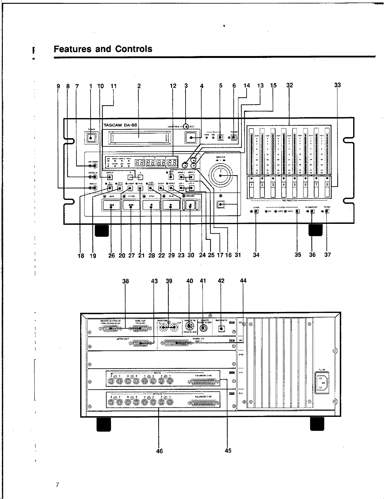
Features and Controls
123 4 5
lllllllll lllll
I
I I I
26 20 27 21 28 22 29 23 30 24 251716 31 34 35 36 37
7
38
43 39
40 41 42 44
Page 4
Skim through this section of the manual to get a bird&eyeview of the DA-88, that way you will be able to locate
information whenever ~0” need. It is not XC~SSIU~ to
memorize all what is here nor to try to build up d&Is into
a systematic whole to get started.
1. POWER switch
Con@& the prwer m the DA-88. See also page 4, “Backup
Fe&we.”
2. Tape loading window
recording. No audio rewrding can correctly be made on
3. CASSETTE IN LED
Lights when a cassette is inside the deck.
4. EJECT key
When pressed, the cassette is ejected.
EJECT ca” operate during stop only.
5. Fs (sampling frequency) switch
Toggles No sampling frequencies (or rates) for your choice.
When formatting a tape yw have to select 48 kHz or 44.1
kHz depending Ron the applicaGons. During play the deck
will aummaGcally switch to the rate at which the. wording
was made, and either of the &vo LEDs will light
accordingly.
NOTE
If you attempt to record additional material to augment
the original cme, and the incoming sampling rate is not
the same as that is previously recorded con the tape,
one of the Fs indicators will flash, warning you that
recording cannot correctly be done.
6. FORMAT key
To fommt a tape is m record it with subcode da@, of which
ABS (absolute) time is one. This ABS data express the
elapsed time from the beginning of the tape, not from any
opdonally selectable. inhxnediate point : hence the name
“absolute.”
Formatting a tape erases whatever is previously recorded on
it. To prevent formatting from starting acciden@lly, the
FORMAT key is not actually a&v&d unless you press it
twice.
IMPORTANT
Audio can be recorded while formatting. l3W iWs wise of
ycu to format the tape from the beginning all the way to
the end before recording audio. This insures against
noise and discontinuity of absolute time data. If you
want to record audio and format a tape at one time,
don’t stop recording by stopping the tape with STOP or
PLAY. Press FIEC FUNCTION instead, which allows the
tape to be continuously formatted up to the end.
7. VARI SPEED switch
When pressed, “PITCW will show in the display and you
can use the v and A keys to change the play (or the wvxd)
speed up to +/-6.0 % in 0.1 % steps.
CAUTION
The pitch change affects the record speed also. Check
to sea that the VARI SPEED LED is turned off unless
you are using the function intentionally.
8. DIGITAL IN switch
Selects either the analog or the digital input. Pressing this
switch to wm on its LED acdwes the DIGITAL I/O port.
Turnin.g off the LED selec@ the. analog inputs (RCA jacks
or multipin connecmr) as the source of the deck.
9. REMOTE switch
When this switch is pressed, and the associated LED lights,
the DA-88 is submitted to the optional RC-848 remote
conwol unit, and all controls are locked out except
DISPLAY (item lo), v and I (item 1 l), and STOP.
10. DISPLAY switch
Each time you press this switch, the following will show
in the digital display window in sequence, as confirmed by
the corresponding LEDs being lit next m the display :
(1) ABS (absolute) time (elapsed time from the beginning
of the tape up to the cwrent position)
Page 5
(‘2.) MEMO 1 point
(3) MEMO 2 point
(4) % of pitch change
0 To go back to ABS time display mode quickly, you can
hold DISPLAY and press A.
11. 7 and 1 keys
Used to enter the following :
15. ERROR LED
0 Crossfade time (p. 17);
0 Offset time (p. 24);
0 Track delay time (p. 21);
0 Pitch change (p. 21);
0 Preroll time (p.17).
Lights when errors occurred at so constraint a rate in digital
data, that they cannot be corrected, and are. submitted to
interpolation to anive at an approximation to the correct
data.
The following can be trimmed or tine tuned with the V and
I keys :
This indicator also lights to indicate that dirt accumulates
on the heads or tape paths, or that the tape is damaged. If
another tape is loaded and the indicator does not turn off,
consult TASCAM or your nearest TASCAM dealer.
0 MEMO points (~22) ;
0 Punch-in and out points (9.17).
See also the 3rd paragraph under the heading. Recommended
tapes, oil page 5.
16. AUTO PLAY key
The keys axe also used together with DISPLAY to get
Automates play start at the end of each autolocation
acces? to :
function.
0
CJ
0
12.
ABS time indication - if you hold DISPLAY and
press A.
Track delay time setting mode - if you hold I and
press DISPLAY.
Crossfade time setting mode - if you hold V and
press DISPLAY.
Digital display wihdow
Shows the ABS time, MEMO 1 point, MEMO 2 point, or
amount of pitch change (or SMPTE time code numbers
when the optional sync board is installed), as selected by
the DISPLAY switch.
The display will also show error messages. For details on
them, see page 26.
0 The display can quickly be switched back to show ABS
time when you hold DISPLAY and press 1 at any time
(except when error messages show).
0 The ABS time display can flicker when the tape is fast
winding (while in FFWD, REW or LOC).
13. WARNING LED
Flashes to warn you that trouble occurred. Error messages
will also then show in the display, specifying what is
wrong. See also page 26.
14. REC INHIBIT LED
Lights when the tape in use is write-protected. Check the
write protect tab on the cassette.
17. MEMO 1 and MEMO 2 keys
Pressing MEMO I stores the current tape location into that
register, to which the tape will be autolocated when
pressing LOC 1. MEMO 2 is similar to MEMO 1, and is
used to capture any point to which you can return by
pressing LOC 2.
NOTE
“MEMV points you recall into the display by pressing
DISPLAY are the points to which the tape will be
autolocated when pressing LOG except when RHSL
lights solid. When RHSL lights solid, “MEMO 1” shows
the punch- in point, and “MEMO 2” the punch-out point,
as established during Rehearsal &fling mode (during
,which RHSL should blink). This does not mean that
punch-in and out points are stored into the MEMO
registers. When they are recalled into the display, the
“MEMO 1” LED only indicates the punch-in point, and
the “MEMO 2” LED the punch-out point.
18. ALL INPUT switch
When pressed to turn on its LBD, all the chacnels’ outputs
are switched to carry signals derived from the inputs,
whatever the transport mode (primarily for alignment).
9
Page 6
19. AUTO INPUT switch
When this switch and INSERT are both previously
activated, the channel inputs selected by REC FUNCTION
are automatically switched to directly feed the outputs
whenever the transport goes into rewind, fast-forward,
shuttle, or stop mode. This allows the talent in studio to
talk to the engineer in control room without having to
change any settings on the mixer.
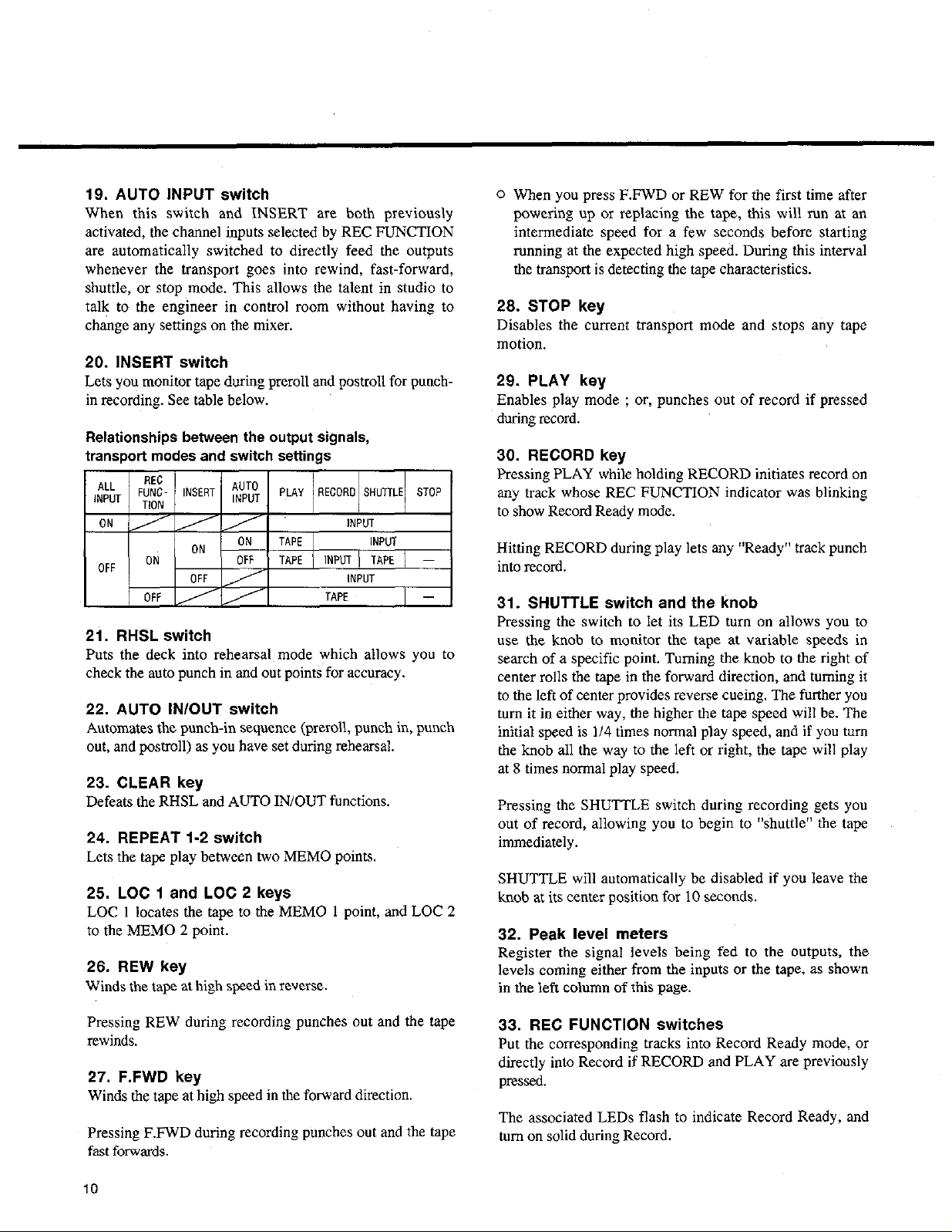
20. INSERT switch
Lets yen monitor tape during preroll and postroll for punch-
in recording. See table below.
Relationships between the output signals,
transport modes and switch settings
21. RHSL switch
Puts the deck into rehearsal mode which allows you to
check the auto punch in and out points for accuracy.
22. AUTO IN/OUT switch
Automates the punch-in sequence (preroll, punch in, punch
out, and postroll) as you have set during rehearsal.
23. CLEAR key
Defeats the RHSL and AUTO IN/OUT functions.
24. REPEAT I-2 switch
Lets the tape play between two MEMO points.
25. LOC I and LOC 2 keys
LOC 1 locates the tape to the MEMO I point, and LOC 2
to the MEMO 2 point.
26. REW key
Winds the tape at high speed in xve~se.
0 When you press F.FWD or REW for the first time after
powering up ok replacing the tape, this will mn at an
intermediate speed for a few seconds before starting
running at the expected high speed. During this interval
the transport is detecting the tape characteristics.
26. STOP key
Disables the current transport mode and stops any tape
motion.
29. PLAY key
Enables play mode ; or, punches out of record if pressed
during record.
30. RECORD key
Pressing PLAY while holding RECORD initiates record on
any track whose REC FUNCTION indicator was blinking
to show Record Ready mode.
Hitting RECORD during play lets any “Ready” track punch
into record.
31. SHUTTLE switch and the knob
Pressing the switch to let its LED turn on allows you to
use the knob to monitor the tape at variable speeds in
search of a specific point. Turning the knob to the right of
center rolls the tape in the forward direction, and turning it
to the left of center provides reverse cueing. The further you
turn it in either way, the higher the tape speed will be. The
initial speed is 1/4 times normal play speed, and if you turn
the knob all the way to the left or right, the tape will play
at 8 times normal play speed.
Pressing the SHUTTLE switch during recording gets you
out of record, allowing you to begin to “shuttle” the tape
immediately.
SHUTTLE will automatically be disabled if you leave the
knob at its ce.nter position for IO seconds.
32. Peak level meters
Register the signal levels being fed to the outputs, the
levels coming either from the inputs or the tape, as shown
in the left column of this page.
Pressing REW during recording punches out and the tape
rewinds.
27. F.FWD key
Winds the tape at high speed in the forward direction.
Pressing F.FWD during recording punches out and the tape
fast forwards.
i0
33. REC FUNCTION switches
Put the corresponding tracks into Record Ready mode, or
directly into Record if RECORD and PLAY axe previously
pressed.
The associated LEDs flash to indicate Record Ready, and
turn on solid during Record.
Page 7
34. CHASE key
Lets the slave DA-88(s) chase and lock to the same ABS
time point as the master. Once locked op. they will play,
record, or fast-wind in sync in response to the commands
from the master.
The installation of the optional SY-88 sync board allows
the DA-88 to run in sync with VTRs or other ATRs
(digital or analog). For more details, refer to the SY-88
manual.
35. CLOCK switch
Selects the clock to which the deck will be referenced.
If the DA-88 is used as a stand-alone deck, it has to be
referenced to the iNT(ernal) clock.
The WORD clock is used when making a digital copy
between the DA-88 and other digital tape machines, or
when letting them run in sync (the optional SY-88 Sync
Board is required).
For the DA-88 to be slaved to VTRs, select VIDEO (the
optional SY-88 sync board is required).
When o”e or more DA-88s are hooked “pas the slaves, the
CLOCK switch on them are locked out (all the associated
LEDs turned off), and they are automatically referenced to
the clock to which the master DA-88 is referenced.
The next two items can operate only when the optional SY88 sync board is installed. For their functions, refer to the
SY-88 manual.
36. TC GENERATE switch
37. TC REC key
Bescheinigung des Herstelle~/lmporteurs
AMTSGLATT 163/1994, VF6 1045/19i4, VFG 1046/1994
,A”‘,abIeX”*?ftiQ”“g,
38. REMOTE IN/SYNC IN and SYNC OUT jacks
When two or more DA-88s are hooked up, a sync signal
and commands from the master’s SYNC OUT jack are fed
into the first slave’s SYNC IN jack; and its SYNC OUT
jack feeds the second slave’s SYNC IN jack, and so on.
The optional RC-848 remote control unit may alternatively
be connected to the SYNC IN jack. The remote can control
a maximum of 6 DA-88s, separately.
m Use ,only the optional PW-88S sync cable ~for
establishing the sync in and out connection
WARNING
Please use only TASCAM cables, as there are very
aoecific cable reauirements. these cables ara
sbecially config”& for comkction to REMOTE
IN/SYNC IN, SYNC OUT, METER UNIT, TDIF-I
(DIGITAL l/O).
(QQ& usa &andard computer cables.)
It is possible to damage certain internal components
by the use of non TASCAM cables. If the use of non
TASCAM cables causes or results in damaged this will
void the Warranty.
1
39. WORD SYNC IN and OUT jacks
The DA-88 can be referenced to the clock derived from the
WORD SYNC IN for it to be slaved to other digital tape
machines. Inversely, they can be slaved to the DA-88 by
letting them be referenced to the clock the DA-88 transmits
from its WORD SYNC OUT. (For the DA-88 and other
digital machines to be synchronized, the optional SY-88
Sync Boani is required.)
The clock the WORD SYNC jacks carries may also be used
when making a digital copy between the DA-88 and other
digital machines.
40. REMOTE IN jack
For connection to the optional RC-808 basic remote
transport control unit.
41. REMOTE PUNCH IN/OUT jack
For connection to the optional RC-30P footswitch.
42. MACHINE ID rotary switch
For tvfo or more DA-885 to be synchronized, they have to
be given their own ID (identification) numbers. Allot “0”
to the master, “1” to the first slave whose SYNC IN is
directly fed with the master’s SYNC OUT and, in a similar
11
Page 8

Note for U.K. Customers
way, allot “2” and upper numbers to the remaining slaves
in sequence, in their order of SYNC IN/OUT connections.
“11” and upper numbers are represented by alphabets ; “I I”
” “12” by “B,” and so’ on.
by “A,
DO NOT cut off the mains plug from this equipment. If
the plug fitted is not suitable for the power points in your
home or the cable is too,short to reach a power point, then
obtain an appropriate safety approved extension lead or
consult your dealer.
If nonetheless the mains olw is cut off. remove the fuse
& dispose of & immediately, to avoid a possible
NOTE
When operating the MACHINE ID switch, make sure
that the deck is turned off or it has no effect
shock hazard by inadvertent connection to the mains
SUPPlY.
If this product is not provided with a mains plw or one
-3 -
has to be fitted, then follow the instructions given b&w:
43. METER~UNIT connector
Carries the output of eight channels and the power for
driving eight of the twenty-four meters on the optional
IMPORTANT. The wires in this mains lead are coloured in
accordance with the following code:
MU-8824 meter unit.
GREEN-AND-YELLOW: EARTH
44. DIGITAL i/O TDIF-1 port
This serial intaface carries all eight channel signals at one
BLUEz
BROW
NEUTRAL
LIVE
time, and allows digital dubbing between two DA-88s
using the optional PW-88D dubbing cable.
For the DA-88 to be connected to other digital machines,
the following optional accessories are available from
TASCAM :
WARNING: This apparatus must be earthed
As the cokx~rs of the wires in the mains lead of this
apparatus may not correspond with the coloured markings
identifying the terminals in your plug proceed as follows.
o IF-88AE : for connection to machines with AES/
EBU digital L’O or SPDIF port.
o IF-88SD : for connection to machines with SDIF-2
port.
45. INPUTS
Jacks I to 8 : receive unbalanced -10 dBV analog sources.
Multipin connector : receives balanced +4 dBm analog
so”rces.
46. OUTPUTS
Jacks I to 8 : for connection to the unbalanced analog
inputs of external equipment.
Multipin connector : for connection to the balanced analog
inputs of external equipment.
The wire which is coloured GWEN-and-YELLOW must be
connected to the terminal in the plug which is marked by
the letter I or by the safety earth symbol * or colcured
GREEN or GREEN-and-YELLOW.
The wire which is coloured BLUE must be connected to the
terminal which is marked with the letter N or coloured
BLACK.
The wire which is coloured BROWN must be connected to
the terminal which is marked with the letter I or coloured
RED.
When reolacins the fuse onlv a correctlv rated amroved tvoe
should be used and be sure to r&fit the fuse cover.
IF IN DOUBT - CONSULT A COMPETENT
ELECTRICIAN.
12
Page 9

Hookup
FtG848 Full-Fuxtion
Rswte Control Unit
Meter Cable (54
Mu-8824 24Ch Meter Unit
PW-88M
RG3OP Footswiich
---e-s--,
PW-88DB8DL Dub4ing Cable
-1
IFXtAE AES/ESU InterfaCe Unit
Mixer
Formattinq a Tape
.SY-88 Sync Board
Before starting to record any audio program on a new tape, it should be formatted,
i.e. it should be time-indexed and given tracking and other subcode data.
NOTES
o Be sure to let formafling start from the very beginning of the tape.
o Once formatting starts, all transporl control buttons’except STOP are
locked out. If you stop the tape before formatting is complete, reformat it
from the beginning.
o Tapes once used for recording video cannot correctly be formatted. Don’t
try to format such tapes.
To format a new tape :
1. Switch on power to the DA-XX.
2. Load a Hi8 tape into the DA-88.
3. Press FORMAT. Its LED will start blinking.
4. Press FORMAT again. Its LED will turn on solid showing that the deck is
ready for formatting.
5. Press the Fs switch to select either of the two sampling rates available. Select
44.1 kHz if the recording will be used as a digital master for CD production.
Or, select the professional standard 48 kHz rate for other applications.
13
Page 10

Audio Recording
G’ Once formatting starts, you cannot change the sampling rate. If you notice
that L wrong rate was selected after formatting starts, stop and rewind the
tape to the beginning and selecf the correct rate before i-e-starting
formatting.
6. Hold RECORD and press PLAY to let formatting start.
When the tape reaches the end and formatting is complete, it will automatically
rewind, stopping at the beginning.
03 Pressing my REC FUNCTION witch after once formatting starts lets audio
be recorded on the corresponding track, But to insure against noise and
discontimities of absolute time data, we recommend that you format all tapes
all the way to the end before using them for audio record.
m If you attempt to record additional material to augmeizt the original and wish
to format the tape from that intermediate point, be sure to mjjiciently inow
back the tape beforehand to prevent an unformatted section being leji in
between.
NOTE
When the tape runs from the previously formatted part into the newly
formatted part, there could be discontinuities of ABS time data. The
tcansition could cause erratic sync if it happens when syncing. If audio
data is present over the transition zone, noise could be heard. The best is
format a tape from start to end without interruption.
mwm
•l
1.
2.
3.
4.
Check to see that all connections are made correctly.
When all connections are checked OK, switch on power to the DA-88 and
other elements of your system.
Load a Hi8 tape into the DA-88.
~3’ Any other tape whatever cannot be loaded on the DA-88
m If the tape has not been formatted already, refer to the section
“Formatting L Tape.”
If you want to record digital audio, press the DIGITAL IN switch to let its
LED light.
If you want to record analog audio, the DIGITAL IN LED should be turned
off.
14
Page 11

Check to see that VARI SPEED is NOT activated. If its LED is on, turn it off
5.
by pressing the switch.
.
I
1
Select the track or tracks to record on by pressing their REC FUNCTION
6.
switch.
If you intend to record analog audio, let the soon% start playing, and adjust its
7.
output level conwok until the DA-Ws meter peaks at the reference level of
“0”. If the OVER indicator lights, it shows distortion occurred.
If you intend to record digital audio, no level adjustment is required.
Hold RECORD and press PLAY to let recording start.
8.
When recording is complete, press STOP.
9.
IO. To prevent recording from accidentally erasing, put the track(s) into Safe mode
by pressing their REC FUNCTION switch again.
Playback
11. Check to see that the audio ootputs are correctly connected to your monitor
system, through a mixer or not.
12. Rewind the tape to the beginning of the recording you want to let play, then
press PLAY.
13. To stop play (detinitely or momentarily), press STOP.
Output Mode Selection
To use the digital outputs, hold down A and press DIGITAL IN when the display is switched to ABS. “Digital”
will appear momentarily on the display, showing the digital output mode is selected. Each time you press
DIGITAL IN while holding down A, the output mode toggles “Digital” and “Analog.” Revert to the analog output
mode when you use tie analog outputs.
15
Page 12

Auto Punch In And Out
REHEARSAL FOR AUTO PUNCH IN AND OUT
-Yr7
.
First check to see that the source is connected to the correct input jack. If you’re
punching into a track just recorded, there is no need of repatching.
During rehearsal, what you hear in the monitor mix and read cm the level meters
will be the same as during recording, but any signal won’t be recorded con tape. So
you can rehearse your punch-in as many times as ycm need without destroying the
origina take at all.
IniM Setting of Punch In and Out Points
I.
2.
3.
4,
5.
6.
7.
8.
9.
Locate the tape to a point lower than the point where you want the track to
punch into word.
Put the punch-in track into Ready mode by pressing its FIEC FUNCTION
switch.
Press the INSERT switch to let its LED light.
Press the RHSL switch. Its LED will start blinking.
KZ You c@vwt qxwte RHSL $REPEAT is activated.
Press PLAY to let the tape stti playing.
When the expected punch-in point is reached, hit RECORD (or press the
optional RC-30P footswitch). This point on the tape is stored into memmy.
You will continue to hear the tape. The monitor does not switch to Source
(Input) because you are still in rehearsal setting mode.
When the expected punch-out pint is reached, hit PLAY (or press the RC-30P
footswitch). This point cm the tape. is stored into memory. The RHSL LED
which was blinking will turn en solid.
After 3 seconds of postroll, the tape will automatically rewind, stopping at a
point 5 seconds lower than the punch-in point you have specified in step 6.
Press PLAY to check the punch in and out points for accuracy.
When the punch-in point is reached the monitor will switch to Source, and
will switch back to Tape at the punch-out point. After 3 seconds of postroll,
the tape will rewind, stopping at the preroll start point.
16
CI
Page 13

Preroll time : It defaults to 5 seconds. If you want longer prerolls, hold 1 or
V and press the other. The display will read “Pr. 00 05 00.” Then, each time
you press A, the display will increment by 1 second, up to 59 minutes, 59
seconds. To decrement the display, pressV. You can hold the key to scroll
through the numerals. After you have entered the desired time, press
DISPLAY to switch the display back to its normal, ABS time display mode.
m You cannon use theA and V keys to get access to the ‘Pr” display
except when the RHSL isjlashging or lights solid or- the AUTO IN/OUT
LED lights solid, and AEtS time shows and the tape is stopped.
The postroll time is fixed to 3 seconds.
0 When the optional RC-848 remote control unit is connected to the DA-88, you
can “fine tune” the postroll time as well.
Fine Tuning In and Out Points
10. Press the DISPLAY Fwitch until the MEMO 1 LED lights. The display then
shows the ABS time of your punch-in point. Then press the 1 key to
increment the punch-in point time, or press the V key to decrement it. Each
time either key is pressed, the ABS time will increment or decrement by 1
second.
To speed up the tuning, you can hold down either 1 or V and press
DISPLAY. Each time you press DISPLAY, the next upper (left) two digits
will fast increment.
11. Likewise, you can fine tune the punch-out point ; first press DISPLAY to let
the MEMO 2 LED tmn on, then change the display with A and V,
12. Audition the new in and out points by pressing PLAY.
Repeat steps 10 and 11 until you are sure that the punch in and out points are
correct.
Entering a Crossfade Time : It defaults to 10 msec. If you want longer
crossfades, hold the V key and press DISPLAY. “CFAdE 10” will show.
Then, each time the A key is pressed, the fade time will increment by 10
msec, up to 90 msec. The V key decrements the time, down to 10 msec.
After you have entzred the desired time, press DISPLAY again.
To reset the crossfade time to IO msec : Hold A or V and press the other
when “C.FAdE” shows in the display.
To check the current crossfade time : Hold V and press DISPLAY at any
time when ABS time shows.
17
Page 14

Punch-in Rehearsal
13. Praaice the pafonnance until you are sure that you will get it right when
acmally recording. Remember, once you punch-in over existing material, that
original signal is erased !
AcWal, Auto Punch In and Out
Once you’re sure yew performance and the in/out points selected are correct, you’re
ready to acwally punch into record. The RIISL LED should be on solid. All
tracks should be in SAFE mode except the one you intend to record.
14. Press AUTO IN/OUT. Its LED will aart blinking.
15. Press PLAY.
The tape will punch inm record, and punch out of record, as progratne& and
after 3 seconds of postroll, the m.pe will rewind, stopping at the preroll start
point, all as you have anticipawd during Rehearsal.
16. Press PLAY to check if the new recording sounds right.
0 Manual punch in and out
To exit Auto In/Out mode :
Press CLEAR. The AUTO IN/OUT LED will turn off, and the RHSL LED as
well.
To accommodate various situations the DA-88 allows you m let the tape manually
punch into and out of record, too.
There are three ways m punch into record mode.
RECORD-Wiggered punch-in
Locate the mpe to a point a few seconds lower than the expected punch-in
1.
point.
2.
Put the punch-in track into Ready mode by pressing its REC FUNCTION
switch.
Press INSERT m Ia its LED turn on.
3.
4
Press PLAY to let the tape start playing.
18
Page 15

5. At the desired punch-in point, hit RECORD. The REC FUNCTION indicator
which was blinking will turn cm solid.
6. Hit PLAY to punch mt of record. The tape will resume playing and the REC
FUNCTION indicator will start blinking as before.
REC FUNCTION-triggered punch-in
I. Check to see that aI1 the REC FUNCTION indicators are off.
2. Press INSERT town on its LED.
3. Locate the tape to a point a few seconds lower than the expected punch-in
point.
4. Hold RECORD and press PLAY to let the tape start playing in Record Ready
mcde.
5. At the desired punch-in point, hit the punch-in track’s REC FUNCTION
switch.
6. At the punch-out point, hit the same REC FUNCTION switch again. The
transport will go into Play mode.
Foobwikh-triggered punch-in
The optional RG3OP footwitch allows you to achieve no-hands punch-in and out.
1. Plug the RC-30P footswitch into the REMOTE PUNCH ON/OUT jack on the
deck’s rear.
2, Locate the tape to a point a few seconds lower than the expected punch-in
point.
3. Put the punch-in track into Ready mode by pressing its REC FUNCTION
switch.
4. Press INSERT m let its LED light.
5. Press the foo&witch to start hearing the track.
6. At the desired mcnnent, press the foovswitch again to punch the track into
xcold.
19
Page 16

7. To punch out of record, press the footswitch again.
8. To stop the tape, press STOP.
In tbis example, we. will “bounce” or combine material from tracks 1-4 onto
etnpty track 8.
I. Connect outputs 1.4 of the DA-88 to inputs I-4 of your mixer, and connect
group out I of the mixer to input 8 of the DA-88.
2.
Set the mixer controls as required (assign channels 1-4 to group out 1, bring up
the group 1 monitor level control, etc).
3. Press the REC FUNCTION switch for track 8 to put this into Ready mode. All
other tracks should be in Safe mode.
4.
Locate the tape to the beginning of the selection, then press PLAY.
5. Slowly increase the group 1 fader until meter 8 peaks at 0 dB. Use the channel
faders (and EQ controls) to set each track’s relative level for the desired balance.
6. When the record level setting is complete, rewind the tape back to the
beginning of the selection.
7. Hold RECORD and press PLAY. Tracks I-4 will be mixed into track 8.
At the end of the selection, press STOP, and rewind the tape to the beginning
8.
of the recording just done.
9, Put track 8 into Safe mode by pressing its REC FUNCTION switch again, then
press PLAY to audition the mix on track 8. If track 8 does not sound right,
make the necessary corrections and redo from the beginning.
Repeat bouncing :
Once you we totally satisfied with the mix on track 8, you can record new material
o” tracks 1-4, then bounce them o”to track 7 or any other empty track the sane
way you bounced onto track 8.
20
Page 17

.
t
I3
You can let the cutput of a specific track lag behind that of others by a maximum
of 7200 samples (Fs). This is like a.n offset you may want to enter so that one
transport will sync to the master with a distance maintained between them.
1 sample corresponds to 22.7 microseconds at 44.1 kHz, and to 20.8 microseconds
at 48 kHz.
When the display shows ABS time, hold the 1 key and press DISPLAY. The
1.
display will read “dl. tr SEL,” prompting you to select the track you want to
lag.
Press REC FUNCTION of the desired track. The display will now read
2.
“tr 1 00 Ov (if you pressed REC FUNCTION 1). prompting you to specify
how many samples the track will lag.
Use the 1 and v keys to enter the desired numerals. Each time you press either
3.
key, the display will increment or decrement in 1 sample steps, up to 7200
samples/down to -200 samples. You can hold the key to scroll through the
numera.ls.
Repeat steps 2 and 3 for other tracks if necessary.
To complete the procedure, press DISPLAY. ABS time will show again.
4.
To reset the current del?y time, hold 1 or v and press the other at any time
when ABS time shows.
Variable Speed Playback
To check the delay time you’ife entered, hold A and press DISPLAY, then
press the necessary channel’s REC FUNCTION at any time wh& ABS time
shows.
During play (or before starting it) yw can change the tape speed up to +/-
6.0% in 0.1 % steps as follows.
1. Press VARI SPEED to let its LED turn on. “PITCW will show in the display.
2. Press the 1 key to speed up the tape, or press the v key to lower the speed.
To def& all pitch changes, bold either A or v and press the other, whatever the
display and the transport mode.
21
Page 18

Autolocation Controls
0 Setting Locating Points
Two locating points (MEMO I and MEMO 2) can be established en a given tape.
To set MEMO points :
F’ress MEMO (1 or 2) at the desired point during Play, or during Stop if the tape is
at the point you want to specify as a locating point
To check MEMO points :
Press the DISPLAY switch (when the tape stops or is running) until the MEMO 1
(or 2) LED lights. The display is now showing the locakm stored into the
correspwding register.
To fine Wne MEMO points :
When the MEMO point ycm want to fine tune is showing in the display, press A
m increment the numbers shown, or press V to decrement them.
TCJ speed up the tuning, you czin hold down either A IX V and press DISPLAY.
Each time YOU press DISPLAY, the next upper (left) two digits will fast
increment
To clear MEMO points :
Hold either A or V and press the other. The locating point currently shown in the
display is erased from memory, as confirmed by “OO:OOzOOz~ appearing instead.
To aumloca& the tape to MEMO points :
Press LOC 1 m locate the tape m the MEMO I point. Press LOC 2 to locak the
tape m the M!ZMO 2 point
At the end of locating funckms the tape will stop unless AUTO PLAY is
previously pressed.
Q Repeat Play
22
Pressing REPEAT lets the tape play between MEMO I and MEMO 2 points over
and over.
The MEMO I point should not be lower than the MEMO 2 point. The DA-88
understands the lower MEMO point as the start point of loop, and the higher
point, as the end.
NOTE
There muat be 4 least 5 seconds between the two MEMO poink
To interrupt momen&wily repeat play, press STOP. Press PLAY to re~umc play.
To exit repeat mode, prw REPEAT.
o If only either MEMO I or MEMO 2 point is established, the tape will repeat
between that MEMO point and the counter zero poinL
Page 19

Multiple-DA-88 System
o Pressing any transport control button during repeat pltiy activates the function
pressed, and repeat play will start again if you -:
Press AUTO PLAY then LOC (whether I or 2) when the tape is at
any point.
OR
Press LOC when the tape is at any point, and, when the tape stops
at the beginning or end of loop, press PLAY.
OR
Press PLAY when the tape is within the loop or at a lower point
than the beginning of the loop.
You can set up a maximum of 16 DA-88s for I28 tracks to let them behave in
sync with sample accuracy, one DA-88 serving as the rimster, and all others as
slaves, this without having to use any external synchronizer, but simply by
connecting their SYNC IN and OUT jacks in series.
0 To synchronize multiple DA-W+ it is imperative that tapes in use are
previously formatted and have ABS time data.
0 You cannot synchroriize tapes if they have been formatted for different
sampling rates.
0 When multiple DA-88s we hooked up, be sure to keep all of them turned on,
whether they are all actually in use or not. If some DA-88s are in record or
play and you turn any others on or off, the recording or playing tapes can
run irregularly.
Connections
Before anything else, check to see that all elements of your system are turned off.
Diagram shows a three-DA-88 system as an example.
SYNC OUT
I
(ID-numtwed 0) (ID-numbered j)
PW43ES
SYNC IN SYNCOUT
1. Connect one end of the optional PW-88s cable to the master’s SYNC OUT,
,ind the other end of the cable to the slave’s SYi% IN.
NOTES
PW-88s
Termination Plug
(ID-numbered 2)
If there are more slaves, connect the second slave’s SYNC OUT to the third
slave’s SYNC IN, and the third slave’s SYNC OUT to the fourth slave’s SYNC
IN, and so on.
23
Page 20

0 Entering an offset
24
UT Use only the optimal PW-82% cables to cascade multiple DA-88s. Any other
cables may seriously damage the machines.
WARNING
Please use only TASCAM cables, as there are very specific cable
requirements, these cables are specially configured for connection to
REMOTE IN/SYNC IN, SYNC OUT, METER UNIT, TDIF-1 (DIGITAL l/O).
(.&&o$ use standard computer cables.)
it is possible to damage certain internal components by the use of non
TASCAM cables. If the use of non TASCAM cables causes or results in
damaged this will void the Warranty.
Allotting ID (Identification) numbers
2. Insert the termination ulw into the last DA+%% SYNC OUT connector. This
plug is supplied with tie %848iPW-88%
NOTE
Do Not forget to attach the termination plug to the SYNC OUT terminal of the
last Slave machine in multiple DA-88 synchronization system or correct
operation is not ensured.
In passing when hooking up only a single DA-88 to the PC-848 remote, the
plug must be inserted into that machine.
3. Locate the MACHINE ID rotary switch on the rear panel of the master DA-S%
and set it to “0”. Similarly, assign “I” to the tirst slave machine, “y to the
second slave, and so on, in their order of SYNC IN/OUT connections.
m Operating the MACHINE ID switch when the machine is turned on has no
&ct at all.
To let slaves chase and lock to the master :
4. Turn on the DA-88s (and other equipment as well a.s required).
5. F’ress CHASE on each of the slave machines. They will all be located to the
satne. time point as the master.
6. F’ress a transport control button whatever on the master machine. The slave
transports will go into the same mode as the master.
You can enter an offset so slave DA-88s lead or lag the master, each by a different
number of hours, minutes, seconds, and frames.
Press DISPLAY 0x1 your slave DA-88 until “OOOOOOOV shows and the OFFSET
indicator lights, then you can use its A and 7 keys to enter the desired offset time
in I frame steps, up to +/-1 hour, 00 minute, 00 second, 00 frame.
To speed up the number entry, you can hold down either A or V and press
DISPLAY. Each time you press DISPLAY, the next upper (left) two digits will
fast increment.
To disable any offset you’ve entered, hold 1 or V and press the other.
Page 21

0 Digital dubbing
With digital recording, how many times dubbing is repeated, no hiss or dismrtion
is added ; you can copy important muldtiack tapes as many times as you need to
creatz work tapes or copies for d&rib&x without having to worry about any
deterioradon.
DIGITAL l/O
PW%3D
DIGITAL l/O
To make a digital copy between DA-88s :
I. Making sure that every equipment of you system is turned off, connect the.
source machine’s DIGITAL WO porl to the target machine’s DIGITAL I/O port
by means of the PW-88D cable.
2. After having made the necessary connecdons, nnn on the whole system.
3. Put the master (source) machine into the Dighal output mode as described on
page 15.
4. Load the master m&itrack tape on the source machine, and an already formaxed
blank tape on the target machine.
5. Check to see that all the REC FUNCTION switches on the source machine are
turned OFF.
6. Check to see that all the REC FUNCTION switches on the target machine are
turned ON.
7. Press CHASE on the target machine, so its tape will be located to the sane
time point as the source machine,
8. Hold RECORD and press PLAY on the source machine to let the master
mul&rack tape start playing. The target machine will automatically go into
record mode, and the master tape will be copied on the taxget tape.
Use the IF-88AE interface unit if you want to make a digital copy between the
DA-88 and other digital machines with AES/EBU Digital I/O or SPDIF port. Or
use the.IF-88SD in&face unit for transferring da@ bewan the DA-88 and other
digital machines with SDIF-2 port. Both units are optionally available. Once you
have connected them, you can copy digital audio from one to the other machine by
following the same prowduE a.s for normal digital audio recording.
Whichever output mode you select (Digital or Analog), audio data is available at both the digital and analog
outputs at one time. But remember the following :
25
Page 22

In the Analog output mode, the analog outputs are timed to compensate for the DIA conversion time as well as the
anticipatory A/D conversion time (42 samples in total as shown). But this in turn disturbs the digital output
timing. On the other hand, in the Digital output mode, the analog outputs will lag because this mode disables the
compensation circuit so that the digital outputs are timed as it should.
Error Messages
No clock is coming in. Or, the CLOCK switch is not set to
match an incoming clock. Check also if the slave machines
(ID-numbered 1.15) are correctly connected in series through
their SYNC IN/OUT connectors, and if the master is IDnumbered 0.
E. k. c u t :
The tape has broken. The only remedy is replacement of the
tape.
E.d <a:
The DIGITAL l/O port is accidentally unplugged.
E.dg:
Condensation occurred on the head drum. Leave the machine for
I or 2 hours with the power switched on until it stabilizes at the
temperature of its operating environment.
g.H I-Bk:
A different tape from the Hi8 is inserted. Use Hi8 tapes only.
E,kh 4n.t:
The tape inserted is too thin (less than 8 pm). Use P6/E6-120
(or PS/E5-90) or shorter tapes.
This shows the incident of error in the mechanics (the “8” is
variable).
If this message appears, switch the power off. then witch it on
again. If the message does not go out. repeat the on/off
switching or try ejecting and reinserting the tape several times.
If all attempts are of no avail, please amtact TASCAM or your
nearest TASCAM dealer.
WARNING LED
This indicator lights to indicate the following :
0
Condensation on the head drum
0
Tape has broken
DIGITAL i/O port accidentally disconnected
0
External clock not coming in correctly
0
0
No time code plug&in (when the opti~nai SY-88 is
installed)
0
Time code setting not matched the type of incoming code
(when the optional SY-88 is installed)
If the indicator lights, check to see whether error messages
specify the problem in the display.
 Loading...