

Page 1

TASCAM
TEAC Professional Division
DA-88
Digital Multitrack Recorder
( OWNER'S MANUAL )
5700141001
Page 2

Important Safety Precautions
CAUTION: TO REDUCE THE RISK OF ELECTRIC SHOCK. DO NOT REMOVE COVER
(OR BACK). NO USER-SERVICEABLE PARTS INSIDE. REFER SERVICING TO
QUALIFIED SERVICE PERSONNEL.
A
CAUTION
RISK OF ELECTRIC SHOCK
DO NOT OPEN
A
The lightning flash with arrowhead symbol, within an equilateral triangle, is intended to alert the user
A
to the presence of uninsulated “dangerous voltage” within the product’s enclosure that may be of
sufficient magnitude to constitute a risk of electric shock to persons.
The exclamation point within an equilateral triangle is intended to alert the user to the presence of
A
This appliance has a serial number located
on the rear panel. Please record the model
number and serial number and retain them for
your records.
Model number
Serial number
_ _ _ _ _ _ _ _ _ _ _ _ _ _ _ _ _ _ _
_ _ _ _ _ _ _ _ _ _ _ _ _ _ _ _ _ _ _
important operating and maintenance (servicing) instructions in the literature accompanying the
appliance.
WARNING: TO PREVENT FIRE OR SHOCK
HAZARD, DO NOT EXPOSE THIS
APPLIANCE TO RAIN OR MOISTURE.
— For U.S.A.
TO THE USER
This equipment has been tested and found to comply with the limits for a Class B digital device, pursuant to Part 15
of the FCC Rules. These limits are designed to provide reasonable protection against interference in a residential
area. This device generates and uses radio frequency energy and if not installed and used in accordance with the
instructions, it may cause interference to radio or TV reception. If this unit does cause interference with TV or radio
reception you can try to correct the interference by one or more of the following measures:
a) Reorient or relocate the receiving antenna.
b) Increase the separation between the equipment and the receiver.
c) Plug the equipment into a different outlet so that it is not on the same circuit as the receiver.
If necessary, consult the dealer or an experienced radio/TV technician for additional suggestions.
CAUTION:
Changes or modifications to this equipment not expressly approved by TEAC CORPORATION for compliance could
void the user's authority to operate this equipment.
THIS DIGITAL APPARATUS DOES NOT EX
CEED THE CLASS B LIMITS FOR RADIO
NOISE EMISSIONS FROM DIGITAL APPARA
TUS AS SET OUT IN THE RADIO INTER
FERENCE REGULATIONS OF THE CANADIAN
DEPARTMENT OF COMMUNICATIONS.
LE PRESENT APPAREIL NUMERIQUE N'EMET
PAS DE BRUITS RADIOELECTRIQUES DE
PASSANT LES LIMITES APPLICABLES AUX
APPAREILS NUMERIQUES DE CLASSE B
PRESCRITES DANS LE REGLEMENT SUR LE
BROUILLAGE RADIOELECTRIQUE EDICTE
PAR LE MINISTERE DES COMMUNICATIONS
DU CANADA.
THE APPLIANCE CONFORMS WITH EEC DIREC
TIVE 87/308/EEC REGARDING INTERFERENCE
SUPPRESSION
CONFORME AL D.M. 13 APRILE 1989
DIRETTIVA CEE/87/308
Page 3
SAFETY INSTRUCTIONS
CAUTION:
• Read all of these instructions.
• Save these instructions for later use.
• Follow all warnings and instructions marked on the
audio equipment.
1. Read Instructions — All the safety and operating instructions
should be read before the appliance is operated.
2. Retain Instructions — The safety and operating instructions
should be retained for future reference.
3. Heed Warnings — All warnings on the appliance and in the
operating instructions should be adhered to.
4. Follow liYstructions — All operating and use instructions
should be followed.
5. Water and Moisture — The appliance should not be used
near water — for example, near a bathtub, washbowl, kitchen
sink, laundry tub, in a wet basement, or near a swimming
pool, etc.
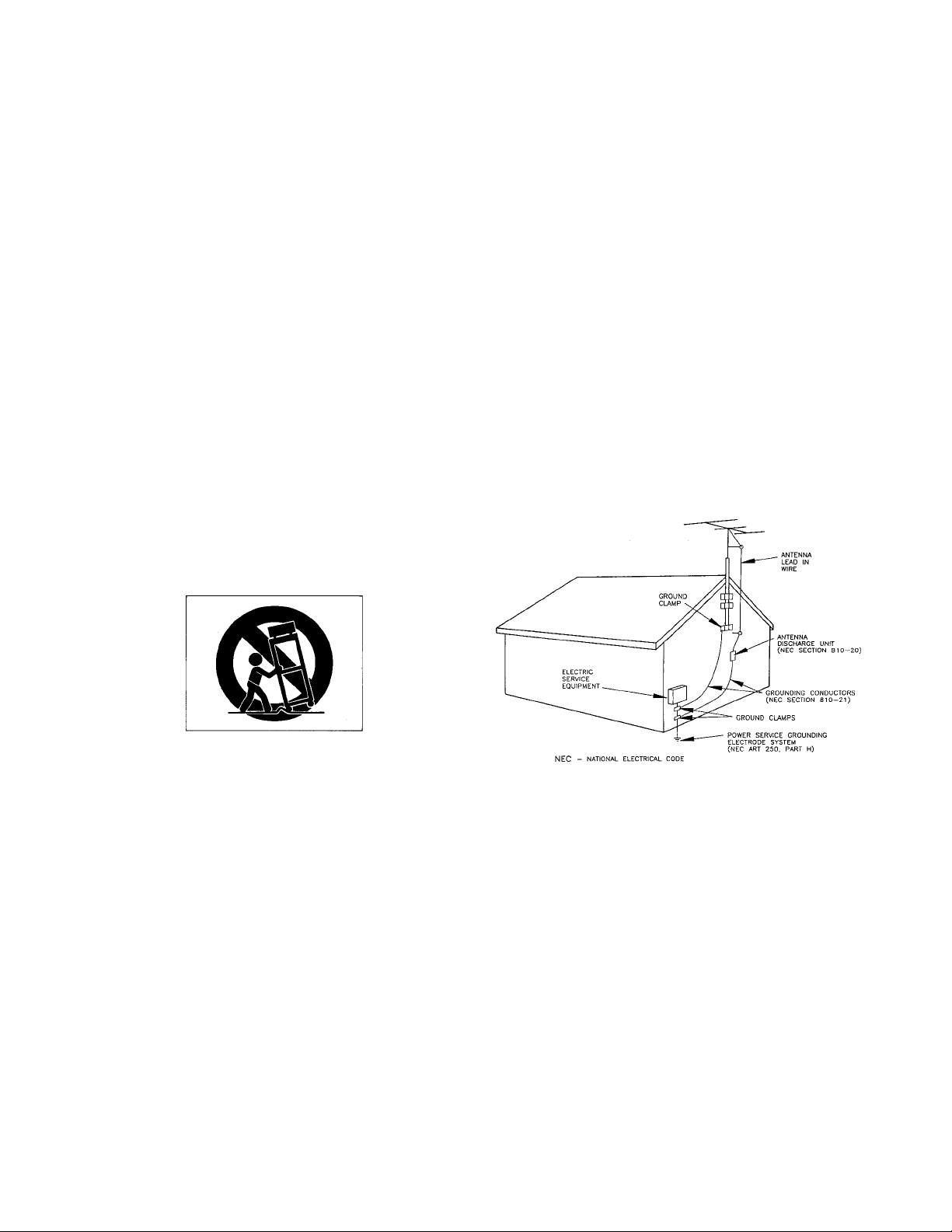
6. Carts and Stands — The appliance should be used only with
a cart or stand that is recommended by the manufacturer.
6A. An appliance and cart combination should be moved with
care. Quick stops, excessive force, and uneven surfaces may
cause the appliance and cart combination to overturn.
13. Cleaning — The appliance should be cleaned only as recom
mended by the manufacturer.
14. Power Lines — An outdoor antenna should be located away
from power lines.
15. Outdoor Antenna Grounding — If an outside antenna is
connected to the receiver, be sure the antenna system is
grounded so as to provide some protection against voltage
surges and built up static charges. Section 810 of the
National Electrical Code, ANSI/NFPA No. 70 — 1984, pro
vides information with respect to proper grounding of the
mast and supporting structure, grounding of the lead-in
wire to an antenna discharge unit, size of grounding con
ductors, location of antenna-discharge unit, connection to
grounding electrodes, and requirements for the grounding
electrode. See Figure below.
EXAMPLE OF ANTENNA GROUNDING
AS PER NATIONAL
ELECTRICAL CODE
7. Wall or Ceiling Mounting — The appliance should demount
ed to a wall or ceiling only as recommended by the manu
facturer.
8. Ventilation — The appliance should be situated so that its
location or position does not interfere with its proper venti
lation. For example, the appliance should not be situated
on a bed, sofa, rug, or similar surface that may block the
ventilation openings; or, placed in a built-in installation,
such as a bookcase or cabinet that may impede the flow of
air through the ventilation openings.
9. Heat — The appliance should be situated away from heat
sources such as radiators, heat registers, stoves, or other
appliances (including amplifiers) that produce heat.
10. Power Sources — The appliance should be connected to a
power supply only of the type described in the operating in
structions or as marked on the appliance.
11. Grounding or Polarization — The precautions that should
be taken so that the grounding or polarization means of an
appliance is not defeated.
12. Power-Cord Protection — Power-supply cords should be
routed so that they are not likely to be walked on or pinch
ed by items placed upon or against them, paying particular
attention to cords at plugs, convenience receptacles, and
the point where they exit from the appliance.
16. Nonuse Periods — The power cord of the appliance should
be unplugged from the outlet when left unused for a long
period of time.
17. Object and Liquid Entry — Care should be taken so that
objects do not fall and liquids are not spilled into the en
closure through openings.
18. Damage Requiring Service — The appliance should be ser
viced by qualified service personnel when:
A. The power-supply cord or the plug has been damaged; or
B. Objects have fallen, or liquid has been spilled into the
appliance; or
C. The appliance has been exposed to rain; or
D. The appliance does not appear to operate normally or
exhibits a marked change in performance; or
E. The appliance has been dropped, or the enclosure dam
aged.
19. Servicing — The user should not attempt to service the
appliance beyond that described in the operating instruc
tions. All other servicing should be referred to qualified
service personnel.
Page 4

Introduction
The TASCAM DA-88 is a digital audio multitrack recorder
designed for use in a variety of professional applications. It
records 8 channels of digital audio data on a readily available
standard Hi8 video cassette tape which is comparable in
handiness and compactness to conventional analog audio
cassette tapes. Other features of the DA-88 include the
following :
o Newly developed TASCAM-exclusive high performance/
high wear resistive rotary 4-head mechanism with
TASCAM original track layout.
o Synchronization of up to 16 DA-88s for a setup of 128
tracks simply by connecting them in series, without
having to use any synchronizer-controller.
o Synchronization with video or other audio recorders
(analog or digital) under SMPTE/EBU time code control
when the optional SY-88 Sync Board is installed.
o Analog inputs and outputs handled by both RCA jacks
(unbalanced) and 25-pin D-sub connectors (balanced), and
digital inputs and outputs by a 25-pin serial I/O port.
o CD quality sound ensured by 16-bit linear quantization
and 48/44.1 kHz sampling rate.
o Auto punch-in/out with rehearsal capability
TABLE OF CONTENTS
Important Safety Precautions..............................................2
Safety Instructions..............................................................3
Introduction
Precautions and Recommendations....................................5
Specifications......................................................................6
Optional Accessories
Features and Controls.....................................................7-12
Front Panel
Rear Panel
Note for U.K. Customers..................................................12
Hookup
Formatting a Tape
Audio Record and Playback
Initial Recording...........................................................14
Punch-in (Insert) Recording
Bouncing Tracks (Ping-pong)
Entering a Track Delay Time.......................................21
Variable Speed Playback..................................................21
Autolocation Controls
Setting Locating Points
Repeat Play...................................................................22
Multiple-DA-88 System..............................................23-25
Synchronization............................................................23
Entering an Offset.........................................................24
Digital Dubbing
Error Messages.................................................................26
...................................................................
..........................................................
...................................................................
....................................................................
.........................................................................
.....................................................
.......................................
.........................................
.......................................
.................................................
................................................
............................................................
13-14
15-21
22-23
.....4
8
11
13
16
20
22
25
6
o 2-point autolocator
o Variable speed playback (up to 6.0% in 0.1 % steps)
Backup Feature
The following are retained in a backup memory each time
the power is turned off (battery life is about 50,000 hours):
o MEMO 1 and 2 points
o Pitch change
o Offset time
o Track delay time
o Crossfade time
o Punch-in and out points
o Preroll time
o DIGITAL IN on/off
o Monitor selection (ALL INPUT, AUTO INPUT and
INSERT)
o CHASE on/off
o CLOCK selection
□ Using this manual
Before actually using the DA-88, please read this
manual thoroughly at least once, so you will know
where to return when you need answers. Even though
a quick glance will get you going, careful study will
ensure that misunderstandings won't slow you down.
Use of capital letters : In general, we use all upper case
type to designate a particular switch, control or connector
label, as in : Hold RECORD and press PLAY.
Page 5
Precautions and Recommendations
□ Environmental conditions
The DA-88 may be used in most area, but to maintain top
performance and prolong operating life, observe the
following environmental limitations :
1) Nominal temperature should be 5 to 35 degrees Celsius
(41 to 95 degrees Fahrenheit).
2) Relative humidity should be 30 to 90% (non
condensing).
3) Strong magnetic fields should not exist nearby,
o Install the unit in an area with proper ventilation.
Beware of Condensation ; When the DA-88 is moved
from a cold to a warm place or used after sudden temperature
change, there is the danger of condensation ; water vapor in
the air could condense on the internal mechanism, making
correct operation impossible and causing damage to the
tape. If condensation occurs, and you attempt to load a tape,
this will automatically be ejected. To prevent this, if you
are going to use the unit in a condition where condensation
could occur, leave the unit for 1 or 2 hours with the power
turned on, then turn the power off before turning it on
again. Do the same when condensation has occurred too.
□ Recommended tapes
The DA-88 transport mechanism is aligned prior to
shipment for SONY Hi8 tapes (MP and ME) to provide
optimum recording and playback performance. As of
October 1993 the following brands and types of Hi8 tape
have proved satisfactory in operation.
MP: SONY, TDK, FUJI, BASF, 3M, DENON,
KONICA
ME: SONY, TDK, MAXELL, BASF
TASCAM cannot assume responsibility for problems
which may arise from inconsistencies in tape or shell
manufacturing quality. Frequent illumination of the DA-88
ERROR LED may indicate the possible presence of taperelated dropouts. Should this occur we recommend that the
tape in use be changed before recording continues.
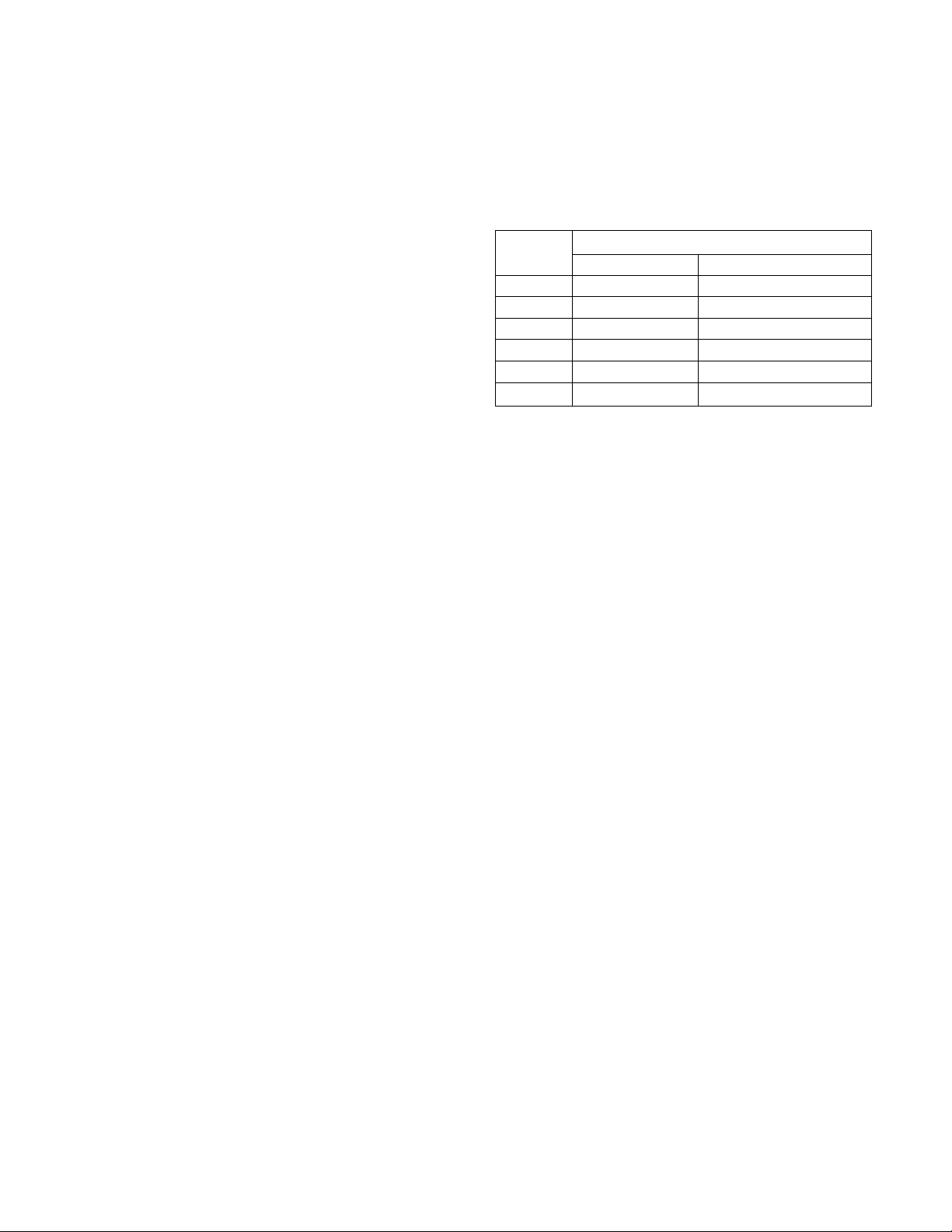
designed for the NTSC or the PAL/SECAM television
system, and therefore on the country where they are sold.
Labelled
time
20 18 25
30
45 40 56
60 54
90
120
P6/E6 (NTSC) P5/E5 (PAL/SECAM)
P6/E6 or P5/E5 is labelled on the tape package.
Actual, available time
27 37
81 113
108
75
—
□ Cleaning the heads
After long periods of use, the heads may become dirty.
They should be cleaned after every 50 hours (or so) of
operation.
Be sure to use a dry cleaning tape designed for 8 mm
video.
First, if the machine is turned on, turn it off.
1. Press and hold both the ▲ and ▼ keys and press the
POWER switch.
"CLEAning" will flash in the display to indicate that the
machine is put into Cleaning mode.
2. Insert your cleaning tape.
Cleaning will start and, about 15 seconds later, the tape
will automatically be ejected, the machine quitting the
cleaning mode.
o You cannot let the cleaning tape run by means of any
transport control buttons. Never try to rewind it for reuse
by any means. Use a new cleaning tape only once thru,
o Excessive cleaning causes premature wearing of the
heads. Don't repeat cleaning 5 times or more at a stretch,
o To maintain performance of the machine, besides head
cleaning (50 hours), a routine maintenance check is
recommended approximately every 500 hours.
CAUTION
Never use tapes longer than 120-minute tape of NTSC
(P6-120, E6-120) or 90-minute tape of PAL/SECAM
(P5-90, E5-90). Also never use tapes which have been
used previously for video recording.
o The DA-88 senses the thickness of tapes inserted, and if
you attempt to load longer tapes than P6-150/E6-150
(NTSC) or P5-120/E5-120 (PAL/SECAM), they will
automatically be ejected.
□ Available record/play time
When used with the DA-88, Hi8 video tapes provide
different record/play times depending on whether they are
□ Others
o To avoid electric shock or other accidents, don't open the
unit to clean inside or perform internal adjustments. The
user should not attempt at any servicing which is not
contained in this Owner's Manual,
o Before turning off the unit, be sure to remove the tape
from the unit. Leaving it in the unit for a long time
could cause damage to the tape,
o Don't cut tapes for any editing purposes. Such tapes
could make correct operation impossible or result in
accumulation of dirt on, or damage to, the heads,
o If a hum or ground loop develops, check the AC power
connection. If necessary, consult a person familiar with
studio grounding techniques.
Page 6

Specifications
Optional Accessories
Transport
Recording Format: 4-rotary head digital recording
Tape : Hi8 video tape
Number of Channels : Eight plus subcode area
Recording Time : 108 minutes using P6/E6-120
tape/113 minutes using P5/E5-90 tape
Tape Speed : 15.9 mm per second
Fast Forward/Rewind Time : Approximately 80 seconds
using P6/E6-120 tape/85 seconds using P5/E5-90 tape
(100 times play speed)
Shuttle Speed : 1/4 to 8 times play speed
Inputs and Outputs
Digital I/O : TDIF (TEAC Digital Interface Format), 25
pin D-sub xl
Analog Input : 25 pin D-sub connector xl, +4 dBm,
10k ohms (balanced)
RCA jack x8, -10 dBV, 50k ohms
(unbalanced)
Output: 25 pin D-sub connector xl, +4 dBm,
75 ohms (balanced)
RCA jack x8, -10 dBV, 250 ohms
(unbalanced)
Sync Input: 15 pin D-sub connector xl
Output: 15 pin D-sub connector xl
Word Sync Input: BNC connector xl
Output: BNC connector x 1
Remote Input: 8 pin DIN connector xl
Remote Punch In/Out: 1/4" phone jack xl
Typical Performance
Sampling Rate : 44.1/48 kHz
Quantization : 16 bit linear
Pitch Control: +1-6% in 0.1 % increments
Frequency Response (Record and Play) :
20 Hz to 20 kHz,+/-0.5 dB
Dynamic Range : Better than 92 dB
Wow and Flutter : Less than measurable limits
Total Harmonic Distortion : 0.007%
□ RC-848 Full-function Remote Control Unit
o 99-point autolocator functions
o ACCESSORY 1 and 2 connectors for controlling
TASCAM (or other) audio machines
o RS-422 connector for controlling VT machines
o Jog/shuttle wheel for locating a specific point at variable
speeds
o Keypad-entered time locations
o Menu-selectable controls of the optional SY-88
synchronizer
□ RC-808 Basic Transport Remote Control Unit
Has duplicates of REC FUNCTION, ALL INPUT, AUTO
INPUT, REHEARSAL, AUTO IN/OUT, CLEAR,
REPEAT, MEMO and LOC in addition to the transport
controls.
□ SY-88 Sync Board
o All SMPTE/EBU time codes supported : Drop 29.97
fps, Non Drop 29.97 fps, 30 fps, 25 fps (EBU), and 24
fps (Film).
o Offset sync with sub-frame accuracy
o Automatic offset entry
a PW-88S Sync Cable
For connecting multiple DA-88s in series when one serves
as the master and others as slaves. One cable establishes
connection between two DA-88s.
□ PW-88D (1 m)/PW-88DL (5 m) Dubbing Cable
For connecting two DA-88s through their digital I/O port
when one serves as the source machine and the other as the
target.
□ MU-8824 24-channel Meter Unit
Allows metering three DA-88s.
□ PW-88M Meter Cable
For connecting the MU-8824 meter unit to the DA-88.
General
Power Requirements :
USA/Canada : 120 V AC, 60 Hz
Europe : 230 V AC, 50 Hz
U.K./Australia : 240 V AC, 50 Hz
Consumption : 74 Watts
Dimensions (WxHxD): 482 mm x 176 mm x 377 mm
Weight: 14 kg
CF Changes in specifications and features may be made
without notice or obligation.
□ IF-88AE Interface Unit
For data communication between the DA-88 and other
digital machines with AES/EBU digital FO or SPDIF.
□ IF-88SD Interface Unit
For data communication between the DA-88 and other
digital machines with SDIF-2.
□ RC-30P Punch-in Footswitch
Page 7
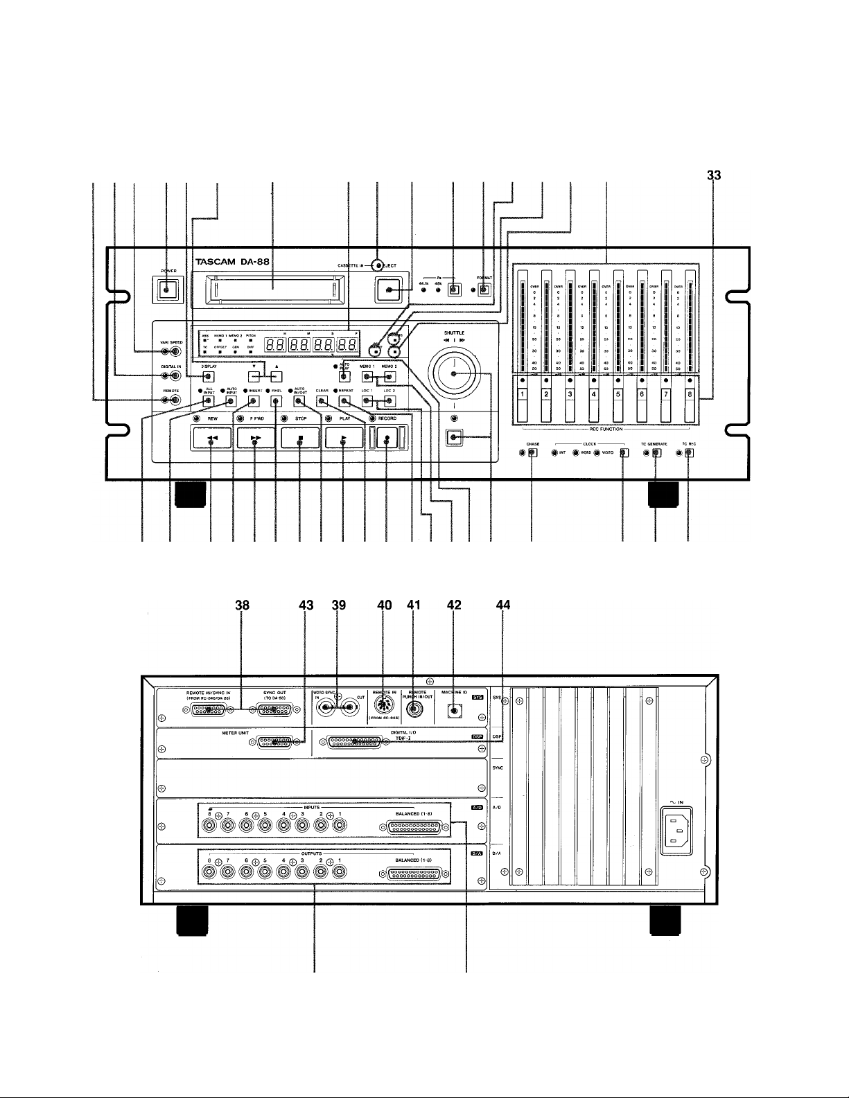
Features and Controls
9 8 7 1 10 11
18 19 26 20 27 21 28 22 29 23 30 24 25 1716 31 34
12 3 4 5 6 14 13 15 32
35 36 37
46
45
Page 8

Skim through this section of the manual to get a bird's-eyeview of the DA-88, that way you will be able to locate
information whenever you need. It is not necessary to
memorize all what is here nor to try to build up details into
a systematic whole to get started.
03" Functions available only when the optional SY-88
Sync Board is installed are not explained here.
Information on them is provided in the SY-88's manual.
6. FORMAT key
To format a tape is to record it with subcode data, of which
ABS (absolute) time is one. This ABS data express the
elapsed time from the beginning of the tape, not from any
optionally selectable intermediate point : hence the name
"absolute."
Formatting a tape erases whatever is previously recorded on
it. To prevent formatting from starting accidentally, the
FORMAT key is not actually activated unless you press it
twice.
FRONT PANEL
1. POWER switch
Controls the power to the DA-88. See also page 4, "Backup
Feature."
2. Tape loading window
NOTE
Don't use any Hi8 tape which was once used for video
recording. No audio recording can correctiy be made on
such tapes.
3. CASSETTE IN LED
Lights when a cassette is inside the deck.
4. EJECT key
When pressed, the cassette is ejected.
EJECT can operate during stop only.
5. Fs (sampling frequency) switch
Toggles two sampling frequencies (or rates) for your choice.
When formatting a tape you have to select 48 kHz or 44.1
kHz depending on the applications. During play the deck
will automatically switch to the rate at which the recording
was made, and either of the two LEDs will light
accordingly.
NOTE
If you attempt to record additional material to augment
the original one, and the incoming sampling rate is not
the same as that is previously recorded on the tape,
one of the Fs indicators will flash, warning you that
recording cannot correctly be done.
IMPORTANT
Audio can be recorded while formatting. But it's wise of
you to format the tape from the beginning all the way to
the end before recording audio. This insures against
noise and discontinuity of absolute time data. If you
want to record audio and format a tape at one time,
don't stop recording by stopping the tape with STOP or
PLAY. Press REC FUNCTION instead, which allows the
tape to be continuously formatted up to the end.
7. VARI SPEED switch
When pressed, "PITCH" will show in the display and you
can use the T and A keys to change the play (or the record)
speed up to +/-6.0 % in 0.1 % steps.
CAUTION
The pitch change affects the record speed also. Check
to see that the VARI SPEED LED is turned off unless
you are using the function intentionally.
8. DIGITAL IN switch
Selects either the analog or the digital input. Pressing this
switch to turn on its LED activates the DIGITAL I/O port.
Turning off the LED selects the analog inputs (RCA jacks
or multipin connector) as the source of the deck.
9. REMOTE switch
When this switch is pressed, and the associated LED lights,
the DA-88 is submitted to the optional RC-848 remote
control unit, and all controls are locked out except
DISPLAY (item 10), ▼ and A (item 11), and STOP.
10. DISPLAY switch
Each time you press this switch, the following will show
in the digital display window in sequence, as confirmed by
the corresponding LEDs being lit next to the display :
(1) ABS (absolute) time (elapsed time from the beginning
of the tape up to the current position)
Page 9

(2) MEMO 1 point
(3) MEMO 2 point
(4) % of pitch change
o To go back to ABS time display mode quickly, you can
hold DISPLAY and press A.
13. WARNING LED
Flashes to warn you that trouble occurred. Error messages
will also then show in the display, specifying what is
wrong. See also page 26.
14. REC INHIBIT LED
Lights when the tape in use is write-protected. Check the
write protect tab on the cassette.
11. T and A keys
Used to enter the following :
o Crossfade time (p. 1,7):
o Offset time (p. 24);
o Track delay time (p. 21);
o Pitch change (p 21);
o Preroll time (p. 17).
The following can be trimmed or fine tuned with the ▼ and
A keys ;
o MEMO points (p.22) ;
o Punch-in and out points (p. 17).
The keys are also used together with DISPLAY to get
access to :
o ABS time indication — if you hold DISPLAY and
press A.
o Track delay time setting mode — if you hold A and
press DISPLAY.
o Crossfade time setting mode — if you hold ▼ and
press DISPLAY.
15. ERROR LED
Lights when errors occurred at so constraint a rate in digital
data, that they cannot be corrected, and are submitted to
interpolation to arrive at an approximation to the correct
data.
This indicator also lights to indicate that dirt accumulates
on the heads or tape paths, or that the tape is damaged. If
another tape is loaded and the indicator does not turn off,
consult TASCAM or your nearest TASCAM dealer.
See also the 3rd paragraph under the heading. Recommended
tapes, on page 5.
16. AUTO PLAY key
Automates play start at the end of each autolocation
function.
17. MEMO 1 and MEMO 2 keys
Pressing MEMO 1 stores the current tape location into that
register, to which the tape will be autolocated when
pressing LOC 1. MEMO 2 is similar to MEMO 1, and is
used to capture any point to which you can return by
pressing LOC 2.
12. Digital display window
Shows the ABS time, MEMO 1 point, MEMO 2 point, or
amount of pitch change (or SMPTE time code numbers
when the optional sync board is installed), as selected by
the DISPLAY switch.
The display will also show error messages. For details on
them, see page 26.
o The display can quickly be switched back to show ABS
time when you hold DISPLAY and press A at any time
(except when error messages show).
o The ABS time display can flicker when the tape is fast
winding (while in F.FWD, REW or LOC).
NOTE
"MEMO" points you recall into the display by pressing
DISPLAY are the points to which the tape will be
autolocated when pressing LOC, except when RHSL
lights solid. When RHSL lights solid, "MEMO 1" shows
the punch- in point, and "MEMO 2" the punch-out point,
as established during Rehearsal Setting mode (during
which RHSL should blink). This does not mean that
punch-in and out points are stored into the MEMO
registers. When they are recalled into the display, the
"MEMO 1" LED only indicates the punch-in point, and
the "MEMO 2" LED the punch-out point.
18. ALL INPUT switch
When pressed to turn on its LED, all the channels' outputs
are switched to carry signals derived from the inputs,
whatever the transport mode (primarily for alignment).
Page 10

19. AUTO INPUT switch
When this switch and INSERT are both previously
activated, the channel inputs selected by REC FUNCTION
are automatically switched to directly feed the outputs
whenever the transport goes into rewind, fast-forward,
shuttle, or stop mode. This allows the talent in studio to
talk to the engineer in control room without having to
change any settings on the mixer.
20. INSERT switch
Lets you monitor tape during preroll and postroll for punchin recording. See table below.
Relationships between the output signals,
transport modes and switch settings
ALL
INPUT
ON
OFF
REC
FUNC
INSERT
TION
ON
OFF TAPE
AUTO
INPUT
ON
OFF INPUT
PLAY RECORD SHUTTLE
ON TAPE INPUT
OFF
TAPE
STOP
INPUT
INPUT TAPE —
—
21. RHSL switch
Puts the deck into rehearsal mode which allows you to
check the auto punch in and out points for accuracy.
22. AUTO IN/OUT switch
Automates the punch-in sequence (preroll, punch in, punch
out, and postroll) as you have set during rehearsal.
23. CLEAR key
Defeats the RHSL and AUTO IN/OUT functions.
24. REPEAT 1-2 switch
Lets the tape play between two MEMO points.
25. LOG 1 and LOC 2 keys
LOG 1 locates the tape to the MEMO 1 point, and LOC 2
to the MEMO 2 point.
26. REW key
Winds the tape at high speed in reverse.
o When you press F.FWD or REW for the first time after
powering up or replacing the tape, this will run at an
intermediate speed for a few seconds before starting
running at the expected high speed. During this interval
the transport is detecting the tape characteristics.
28. STOP key
Disables the current transport mode and stops any tape
motion.
29. PLAY key
Enables play mode
or, punches out of record if pressed
during record.
30. RECORD key
Pressing PLAY while holding RECORD initiates record on
any track whose REC FUNCTION indicator was blinking
to show Record Ready mode.
Hitting RECORD during play lets any "Ready" track punch
into record.
31. SHUTTLE switch and the knob
Pressing the switch to let its LED turn on allows you to
use the knob to monitor the tape at variable speeds in
search of a specific point. Turning the knob to the right of
center rolls the tape in the forward direction, and turning it
to the left of center provides reverse cueing. The further you
turn it in either way, the higher the tape speed will be. The
initial speed is 1/4 times normal play speed, and if you turn
the knob all the way to the left or right, the tape will play
at 8 times normal play speed.
Pressing the SHUTTLE switch during recording gets you
out of record, allowing you to begin to "shuttle" the tape
immediately.
SHUTTLE will automatically be disabled if you leave the
knob at its center position for 10 seconds.
32. Peak level meters
Register the signal levels being fed to the outputs, the
levels coming either from the inputs or the tape, as shown
in the left column of this page.
Pressing REW during recording punches out and the tape
rewinds.
27. F.FWD key
Winds the tape at high speed in the forward direction.
Pressing F.FWD during recording punches out and the tape
fast forwards.
10
33. REC FUNCTION switches
Put the corresponding tracks into Record Ready mode, or
directly into Record if RECORD and PLAY are previously
pressed.
The associated LEDs flash to indicate Record Ready, and
turn on solid during Record.
Page 11

34. CHASE key
Lets the slave DA-88(s) chase and lock to the same ABS
time point as the master. Once locked up, they will play,
record, or fast-wind in sync in response to the commands
from the master.
The installation of the optional SY-88 sync board allows
the DA-88 to run in sync with VTRs or other ATRs
(digital or analog). For more details, refer to the SY-88
manual.
35. CLOCK switch
Selects the clock to which the deck will be referenced.
If the DA-88 is used as a stand-alone deck, it has to be
referenced to the INT(emal) clock.
The WORD clock is used when making a digital copy
between the DA-88 and other digital tape machines, or
when letting them run in sync (the optional SY-88 Sync
Board is required).
For the DA-88 to be slaved to VTRs, select VIDEO (the
optional SY-88 sync board is required).
When one or more DA-88s are hooked up as the slaves, the
CLOCK switch on them are locked out (all the associated
LEDs turned off), and they are automatically referenced to
the clock to which the master DA-88 is referenced.
The next two items can operate only when the optional SY-
88 sync board is installed. For their functions, refer to the
SY-88 manual.
36. TC GENERATE switch
37. TC REC key
REAR PANEL
38. REMOTE IN/SYNC IN and SYNC OUT jacks
When two or more DA-88s are hooked up, a sync signal
and commands from the master's SYNC OUT jack are fed
into the first slave's SYNC IN jack; and its SYNC OUT
jack feeds the second slave's SYNC IN jack, and so on.
The optional RC-848 remote control unit may alternatively
be connected to the SYNC IN jack. The remote can control
a maximum of 6 DA-88s, separately.
lEF Use only the optional PW-88S sync cable for
establishing the sync in and out connection.
WARNING
Please use only TASCAM cables, as there are very
specific cable requirements, these cables are
specially configured for connection to REMOTE
IN/SYNC IN, SYNC OUT, METER UNIT, TDIF-1
(DIGITAL I/O).
(Do Not use standard computer cables.)
It is possible to damage certain internal components
by the use of non TASCAM cables. If the use of non
TASCAM cables causes or results in damaged this will
void the Warranty.
39. WORD SYNC IN and OUT jacks
The DA-88 can be referenced to the clock derived from the
WORD SYNC IN for it to be slaved to other digital tape
machines. Inversely, they can be slaved to the DA-88 by
letting them be referenced to the clock the DA-88 transmits
from its WORD SYNC OUT. (For the DA-88 and other
digital machines to be synchronized, the optional SY-88
Sync Board is required.)
Bescheinigung des Herstellers/Importeurs
Hiermit wird bescheinigt, daß der/die/das
_______
(Gerät, Typ, Bezeichnung)
in Übereinstimmung mitden Bestimmungen der
TASCAM DA-88 DAT-Recorder
_________
AMTSBLATT 163/1984, VFG 1045/1984, VFG 1046/1984
(Amtsblattverfügung)
funk-entstört ist.
Der Deutschen Bundespost wurde das inverkehrbringen
dieses Gerätes angezeigt und die Berechtigung zur Über
prüfung der Serie auf Einhaitung der Bestimmungen eingeräumt.
TEAC CORPORATION
Name des Herstellers/Importeurs
The clock the WORD SYNC jacks carries may also be used
when making a digital copy between the DA-88 and other
digital machines.
40. REMOTE IN jack
For connection to the optional RC-808 basic remote
transport control unit.
41. REMOTE PUNCH IN/OUT jack
For connection to the optional RC-30P footswitch.
42. MACHINE ID rotary switch
For two or more DA-88s to be synchronized, they have to
be given their own ID (identification) numbers. Allot "0"
to the master, "1" to the first slave whose SYNC IN is
directly fed with the master's SYNC OUT; and, in a similar
11
Page 12

Note for U.K. Customers
way, allot "2" and upper numbers to the remaining slaves
in sequence, in their order of SYNC IN/OUT connections.
''11 " and upper numbers are represented by alphabets ; "11 "
by "A," "12" by "B,"and so on.
c? Don't assign the same ID number to two or more
machines. This may cause incorrect functions to them.
NOTE
When operating the MACHINE ID switch, make sure
that the deck is turned off or it has no effect.
43. METER UNIT connector
Carries the output of eight channels and the power for
driving eight of the twenty-four meters on the optional
MU-8824 meter unit.
44. DIGITAL I/o TDIF-1 port
This serial interface carries all eight channel signals at one
time, and allows digital dubbing between two DA-88s
using the optional PW-88D dubbing cable.
For the DA-88 to be connected to other digital machines,
the following optional accessories are available from
TASCAM :
DO NOT cut off the mains plug from this equipment. If
the plug fitted is not suitable for the power points in your
home or the cable is too short to reach a power point, then
obtain an appropriate safety approved extension lead or
consult your dealer.
If nonetheless the mains plug is cut off, remove the fuse
and dispose of the plus immediately, to avoid a possible
shock hazard by inadvertent connection to the mains
supply.
If this product is not provided with a mains plug, or one
has to be fitted, then follow the instructions given below:
IMPORTANT. The wires in this mains lead are coloured in
accordance with the following code:
GREEN-AND-YELLOW: EARTH
BLUE: NEUTRAL
BROWN: LIVE
WARNING: This apparatus must be earthed.
As the colours of the wires in the mains lead of this
apparatus may not correspond with the coloured markings
identifying the terminals in your plug proceed as follows.
o IF-88AE : for connection to machines with AES/
EBU digital I/O or SPDIE port,
o IF-88SD : for connection to machines with SDIF-2
port.
45. INPUTS
Jacks 1 to 8 : receive unbalanced -10 dBV analog sources.
Multipin connector : receives balanced -t-4 dBm analog
sources.
46. OUTPUTS
Jacks 1 to 8 : for connection to the unbalanced analog
inputs of external equipment.
Multipin connector : for connection to the balanced analog
inputs of external equipment.
H = HOT
C = COLD
G = GROUND
The wire which is coloured GREEN-and-YELLOW must be
connected to the terminal in the plug which is marked by
the letter E or by the safety earth symbol or coloured
GREEN or GREEN-and-YELLOW.
The wire which is coloured BLUE must be connected to the
terminal which is marked with the letter N or coloured
BLACK.
The wire which is coloured BROWN must be connected to
the terminal which is marked with the letter L or coloured
RED.
When replacing the fuse only a correctly rated approved type
should be used and be sure to re-fit the fuse cover.
IF IN DOUBT
CONSULT A COMPETENT
ELECTRICIAN.
12
Page 13

Hookup
RC-808
Basic Transport
Remote Control
Unit
(5
#► To the next machine's
SYNC IN
цццдцAцd ¿Дiiцiiцi MÄÄÄööö
iiiiöfiiiiiöi ¿aaaaflafl
aaea üQ DOüO
iaea
cpI'o ÖÖ 0000
1 aä B i e e
□ □ '^if0QQS
□ OO s
0
RC-848 Full-Function
Remote Control Unit
Meter Cable (5m)
MU-8824 24-Ch Meter Unit
0Da
0 00 B
aoasaiiB
PW-88M
Formatting a Tape
SY-88 Sync Board
IF-88SD SDIF-2 Interface Unit
Before starting to record any audio program on a new tape, it should be formatted,
i.e. it should be time-indexed and given tracking and other subcode data.
✓ 8% *-*
I
---
Fs-
44.1k 48k
9 9
□
NOTES
o Be sure to let formatting start from the very beginning of the tape.
o Once formatting starts, all transport control buttons except STOP are
locked out. If you stop the tape before formatting is complete, reformat it
from the beginning.
o Tapes once used for recording video cannot correctly be formatted. Don't
try to format such tapes.
To format a new tape :
1. Switch on power to the DA-88.
2. Load a Hi8 tape into the DA-88.
3. Press FORMAT. Its LED will start blinking.
4. Press FORMAT again. Its LED will turn on solid showing that the deck is
ready for formatting.
5. Press the Fs switch to select either of the two sampling rates available. Select
44.1 kHz if the recording will be used as a digital master for CD production.
Or, select the professional standard 48 kHz rate for other applications.
13
Page 14

\ I / \ I /
—PI-AY —-^•«ECORD
/1 \
-------
O’ Once formatting starts, you cannot change the sampling rate. If you notice
that a wrong rate was selected after formatting starts, stop and rewind the
tape to the beginning and select the correct rate before re-starting
formatting.
6. Hold RECORD and press PLAY to let formatting start.
0
Audio Recording
When the tape reaches the end and formatting is complete, it will automatically
rewind, stopping at the beginning.
O Pressing any REC FUNCTION switch after once formatting starts lets audio
be recorded on the corresponding track. But to insure against noise and
discontinuities of absolute time data, we recommend that you format all tapes
all the way to the end before using them for audio record.
O’ If you attempt to record additional material to augment the original and wish
to format the tape from that intermediate point, be sure to sufficiently move
back the tape beforehand to prevent an unformatted section being left in
between.
NOTE
When the tape runs from the previously formatted part into the newly
formatted part, there could be discontinuities of ABS time data. The
transition could cause erratic sync if it happens when syncing. If audio
data is present over the transition zone, noise could be heard. The best is
format a tape from start to end without interruption.
INITIAL RECORDING
14
DpITAL IN
1. Check to see that all connections are made correctly.
2. When all connections are checked OK, switch on power to the DA-88 and
other elements of your system.
3. Load a Hi8 tape into the DA-88.
O’ Any other tape whatever cannot be loaded on the DA-88.
o If the tape has not been formatted already, refer to the section
"Formatting a Tape."
4. If you want to record digital audio, press the DIGITAL IN switch to let its
LED light.
If you want to record analog audio, the DIGITAL IN LED should be turned
off.
Page 15

5. Check to see that VARI SPEED is NOT activated. If its LED is on, turn it off
by pressing the switch.
6. Select the track or tracks to record on by pressing their REC FUNCTION
switch.
7. If you intend to record analog audio, let the source start playing, and adjust its
output level controls until the DA-88's meter peaks at the reference level of
"0". If the OVER indicator lights, it shows distortion occurred.
If you intend to record digital audio, no level adjustment is required.
— PLAY ”” (g^ECORD
—®>— PLAY
nL
8. Hold RECORD and press PLAY to let recording start.
9. When recording is complete, press STOP.
10. To prevent recording from accidentally erasing, put the track(s) into Safe mode
by pressing their REC FUNCTION switch again.
Playback
11. Check to see that the audio outputs are correctly connected to your monitor
system, through a mixer or not.
12. Rewind the tape to the beginning of the recording you want to let play, then
press PLAY.
13. To stop play (definitely or momentarily), press STOP.
Output Mode Selection
To use the digital outputs, hold down ▲ and press DIGITAL IN when the display is switched to ABS. "Digital"
will appear momentarily on the display, showing the digital output mode is selected. Each time you press
DIGITAL IN while holding down ▲, the output mode toggles "Digital" and "Analog." Revert to the analog output
mode when you use the analog outputs.
15
Page 16

POfJCH-ifJ CSMSERÌl FIECOeOINQ
First check to see that the source is connected to the correct input jack. If you're
punching into a track just recorded, there is no need of repatching.
□ Auto Punch In And Out
d
□
REHEARSAL FOR AUTO PUNCH IN AND OUT
During rehearsal, what you hear in the monitor mix and read on the level meters
will be the same as during recording, but any signal won't be recorded on tape. So
you can rehearse your punch-in as many times as you need without destroying the
original take at all.
Initial Setting of Punch In and Out Points
1. Locate the tape to a point lower than the point where you want the track to
punch into record.
2. Put the punch-in track into Ready mode by pressing its REC FUNCTION
switch.
3. Press the INSERT switch to let its LED light.
4. Press the RHSL switch. Its LED will start blinking.
TT You cannot operate RHSL if REPEAT is activated.
5. Press PLAY to let the tape start playing.
16
PLAy
6. When the expected punch-in point is reached, hit RECORD (or press the
optional RC-30P footswitch). This point on the tape is stored into memory.
You will continue to hear the tape. The monitor does not switch to Source
(Input) because you are still in rehearsal setting mode.
7. When the expected punch-out point is reached, hit PLAY (or press the RC-30P
footswitch). This point on the tape is stored into memory. The RHSL LED
which was blinking will turn on solid.
8. After 3 seconds of postroll, the tape will automatically rewind, stopping at a
point 5 seconds lower than the punch-in point you have specified in step 6.
9. Press PLAY to check the punch in and out points for accuracy.
When the punch-in point is reached the monitor will switch to Source, and
will switch back to Tape at the punch-out point. After 3 seconds of postroll,
the tape will rewind, stopping at the preroll start point.
Page 17

□
T A
□ □
\i/
Preroll time : It defaults to 5 seconds. If you want longer prerolls, hold ▲ or
▼ and press the other. The display will read "Pr. 00 05 00." Then, each time
you press A, the display will increment by 1 second, up to 59 minutes, 59
seconds. To decrement the display, pressV. You can hold the key to scroll
through the numerals. After you have entered the desired time, press
DISPLAY to switch the display back to its normal, ABS time display mode.
You cannot use the A. and T keys to get access to the "Pr" display
except when the RHSL is flashging or lights solid or the AUTO IN/OUT
LED lights solid, and ABS time shows and the tape is stopped.
The postroll time is fixed to 3 seconds.
o When the optional RC-848 remote control unit is connected to the DA-88, you
can "fine tune" the postroll time as well.
Fine Tuning In and Out Points
10. Press the DISPLAY switch until the MEMO 1 LED lights. The display then
shows the ABS time of your punch-in point. Then press the A key to
increment the punch-in point time, or press the T key to decrement it. Each
time either key is pressed, the ABS time will increment or decrement by 1
second.
To speed up the tuning, you can hold down either A or T and press
DISPLAY. Each time you press DISPLAY, the next upper (left) two digits
will fast increment.
11. Likewise, you can fine tune the punch-out point; first press DISPLAY to let
the MEMO 2 LED turn on, then change the display with A and T.
12. Audition the new in and out points by pressing PLAY.
Repeat steps 10 and 11 until you are sure that the punch in and out points are
correct.
Entering a Crossfade Time : It defaults to 10 msec. If you want longer
crossfades, hold the T key and press DISPLAY. "C.FAdE 10" will show.
Then, each time the A key is pressed, the fade time will increment by 10
msec, up to 90 msec. The ▼ key decrements the time, down to 10 msec.
After you have entered the desired time, press DISPLAY again.
To reset the crossfade time to 10 msec : Hold A or ▼ and press the other
when "C.FAdE" shows in the display.
To check the current crossfade time : Hold ▼ and press DISPLAY at any
time when ABS time shows.
17
Page 18

jUJS
PLAY
----
Punch-in Rehearsal
13. Practice the performance until you are sure that you will get it right when
actually recording. Remember, once you punch-in over existing material, that
original signal is erased !
Actual, Auto Punch In and Out
Once you're sure your performance and the in/out points selected are correct, you're
ready to actually punch into record. The RHSL LED should be on solid. All
tracks should be in SAFE mode except the one you intend to record.
14. Press AUTO IN/OUT. Its LED will start blinking.
15. Press PLAY.
The tape will punch into record, and punch out of record, as programed; and
after 3 seconds of postroll, the tape will rewind, stopping at the preroll start
point, all as you have anticipated during Rehearsal.
Review
16. Press PLAY to check if the new recording sounds right.
□
□ Manual punch in and out
— ••+WSERT
V.
□
N.' ^
PLAY
/» 1 X
________
To exit Auto In/Out mode :
Press CLEAR. The AUTO IN/OUT LED will turn off, and the RHSL LED as
well.
To accommodate various situations the DA-88 allows you to let the tape manually
punch into and out of record, too.
There are three ways to punch into record mode.
RECORD-triggered punch-in
1. Locate the tape to a point a few seconds lower than the expected punch-in
point.
2. Put the punch-in track into Ready mode by pressing its REC FUNCTION
switch.
3. Press INSERT to let its LED turn on.
4. Press PLAY to let the tape start playing.
18
Page 19

___
PLAY — (#)-ft€CORD
—- ^Ys
5. At the desired punch-in point, hit RECORD. The REC FUNCTION indicator
which was blinking will turn on solid.
6. Hit PLAY to punch out of record. The tape will resume playing and the REC
FUNCTION indicator will start blinking as before.
REC FUNCTION-triggered punch-in
1. Check to see that all the REC FUNCTION indicators are off.
-•insert
<f I s
□
PLAY ‘^^^tECORD
✓ y V
>
IIHI
s, s ^ ✓ /
■(®— PLAY — (®-«ECORD /
►
•
1/1
- IIHI
2. Press INSERT to'turn on its LED.
3. Locate the tape to a point a few seconds lower than the expected punch-in
point.
4. Hold RECORD and press PLAY to let the tape start playing in Record Ready
mode.
5. At the desired punch-in point, hit the punch-in track's REC FUNCTION
switch.
6. At the punch-out point, hit the same REC FUNCTION switch again. The
transport will go into Play mode.
Footswitch-triggered punch-in
The optional RC-30P footswitch allows you to achieve no-hands punch-in and out.
1. Plug the RC-30P footswitch into the REMOTE PUNCH ON/OUT jack on the
deck's rear.
— #-4MSERT
/Tn
□
2. Locate the tape to a point a few seconds lower than the expected punch-in
point.
3. Put the punch-in track into Ready mode by pressing its REC FUNCTION
switch.
4. Press INSERT to let its LED light.
5. Press the footswitch to start hearing the track.
6. At the desired moment, press the footswitch again to punch the track into
record.
19
Page 20

\ «/
BOUMCiNG TRACKS (PING-PCr>lG)
7. To punch out of record, press the footswitch again.
8. To stop the tape, press STOP.
In this example, we will "bounce" or combine material from tracks 1-4 onto
empty track 8.
1. Connect outputs 1-4 of the DA-88 to inputs 1-4 of your mixer, and connect
group out 1 of the mixer to input 8 of the DA-88.
2. Set the mixer controls as required (assign channels 1-4 to group out 1, bring up
the group 1 monitor level control, etc).
3. Press the REC FUNCTION switch for track 8 to put this into Ready mode. All
other tracks should be in Safe mode.
w
—(®)“- PLAY
AfS
STOP
.....
4. Locate the tape to the beginning of the selection, then press PLAY.
5. Slowly increase the group 1 fader until meter 8 peaks at 0 dB. Use the channel
faders (and EQ controls) to set each track's relative level for the desired balance.
6. When the record level setting is complete, rewind the tape back to the
beginning of the selection.
7. Hold RECORD and press PLAY. Tracks 1-4 will be mixed into track 8.
8. At the end of the selection, press STOP, and rewind the tape to the beginning
of the recording just done.
.
9. Put track 8 into Safe mode by pressing its REC FUNCTION switch again, then
press PLAY to audition the mix on track 8. If track 8 does hot sound right,
make the necessary corrections and redo from the beginning.
Repeat bouncing :
Once you are totally satisfied with the mix on track 8, you can record new material
on tracks 1-4, then bounce them onto track 7 or any other empty track the same
way you bounced onto track 8.
20
Page 21

ENTERING A TRACK DELAY TIME
A / DISPLAY
You can let the output of a specific track lag behind that of others by a maximum
of 7200 samples (Fs). This is like an offset you may want to enter so that one
transport will sync to the master with a distance maintained between them.
1 sample corresponds to 22.7 microseconds at 44.1 kHz, and to 20.8 microseconds
at 48 kHz.
1. When the display shows ABS time, hold the A key and press DISPLAY. The
display will read "dl. tr SEL," prompting you to select the track you want to
lag.
2. Press REC FUNCTION of the desired track. The display will now read
"tr 1 00 00" (if you pressed REC FUNCTION 1), prompting you to specify
how mamy samples the track will lag.
T A
□ □
□
□ □
Variable Speed Playback
3. Use the A and T keys to enter the desired numerals. Each time you press either
key, the display will increment or decrement in 1 sample steps, up to 7200
samples/down to -200 samples. You can hold the key to scroll through the
numerals.
Repeat steps 2 and 3 for other tracks if necessary.
4. To complete the procedure, press DISPLAY. ABS time will show again.
To reset the current delay time, hold A or T and press the other at any time
when ABS time shows.
To check the delay time you've entered, hold A and press DISPLAY, then
press the necessary channel's REC FUNCTION at any time when ABS time
shows.
During play (or before starting it) you can change the tape speed up to +/-
6.0% in 0.1 % steps as follows.
VARI SPEED
T
□
T
A
□
□A□
1. Press VARI SPEED to let its LED turn on. "PITCH" will show in the display.
2. Press the A key to speed up the tape, or press the T key to lower the speed.
To defeat all pitch changes, hold either A or T and press the other, whatever the
display and the transport mode.
21
Page 22

Autolocation Controls
□ Setting Locating Points
MEMO 1
□
DISPLAY
□
T A
T A
□ □
LOG 1
□
□ □
Two locating points (MEMO 1 and MEMO 2) can be established on a given tape.
To set MEMO points :
Press MEMO (1 or 2) at the desired point during Play, or during Stop if the tape is
at the point you want to specify as a locating point.
To check MEMO points ;
Press the DiSPLAY switch (when the tape stops or is running) until the MEMO 1
(or 2) LED lights. The display is now showing the location stored into the
corresponding register.
To fine tune MEMO points :
When the MEMO point you want to fine tune is showing in the display, press A
to increment the numbers shown, or press ▼ to decrement them.
To speed up the tuning, you can hold down either A or T and press DISPLAY.
Each time you press DISPLAY, the next upper (left) two digits will fast
increment.
To clear MEMO points :
Hold either A or T and press the other. The locating point currently shown in the
display is erased from memory, as confirmed by "00:00:00:00" appearing instead.
To autolocate the tape to MEMO points :
Press LOG 1 to locate the tape to the MEMO 1 point. Press LOG 2 to locate the
tape to the MEMO 2 point.
At the end of locating functions the tape will stop unless AUTO PLAY is
previously pressed.
□ Repeat Play
MEMO]
Outside the
repeat loop
Repeat segment
vt/
—A-repeat
/0
□ □ □
MEMO 2
----
►
Outside the
repeat loop
ICF The LOC keys cannot operate during rewind, punch-in/out process, or when
two or more DA-88s are hooked up and the slaves are chasing the master.
Pressing REPEAT lets the tape play between MEMO 1 and MEMO 2 points over
and over.
The MEMO 1 point should not be lower than the MEMO 2 point. The DA-88
understands the lower MEMO point as the start point of loop, and the higher
point, as the end.
To interrupt momentarily repeat play, press STOP. Press PLAY to resume play.
To exit repeat mode, press REPEAT.
o If only either MEMO 1 or MEMO 2 point is established, the tape will repeat
between that MEMO point and the counter zero point.
22
Page 23

Multiple-DA-88 System
SYNCHRONIZATtON
o Pressing any transport control button during repeat play activates the function
pressed, and repeat play will start again if you —:
Press AUTO PLAY then LOG (whether 1 or 2) when the tape is at
any point.
OR
Press LOG when the tape is at any point, and, when the tape stops
at the beginning or end of loop, press PLAY.
OR
Press PLAY when the tape is within the loop or at a lower point
than the beginning of the loop.
You can set up a maximum of 16 DA-88s for 128 tracks to let them behave in
sync with sample accuracy, one DA-88 serving as the master, and all others as
slaves, this without having to use any external synchronizer, but simply by
connecting their SYNC IN and OUT jacks in series.
NOTES
To synchronize multiple DA-88s, It is imperative that tapes in use are
previously formatted and have ABS time data.
You cannot synchronize tapes if they have been formatted for different
sampling rates.
When multiple DA-88s are hooked up, be sure to keep all of them turned on,
whether they are all actually in use or not. If some DA-88s are in record or
play and you turn any others on or off, the recording or playing tapes can
run irregularly.
Connections
Before anything else, check to see that all elements of your system are turned off.
Diagram shows a three-DA-88 system as an example.
1. Connect one end of the optional PW-88S cable to the master's SYNC OUT,
and the other end of the cable to the slave's SYNC IN.
If there are more slaves, connect the second slave's SYNC OUT to the third
slave's SYNC IN, and the third slave's SYNC OUT to the fourth slave's SYNC
IN, and so on.
23
Page 24

D3* Use only the optional PW-88S cables to cascade multiple DA-88s. Any other
cables may seriously damage the machines.
WARNING
Please use only TASCAM cables, as there are very specific cable
requirements, these cables are specially configured for connection to
REMOTE IN/SYNC IN, SYNC OUT, METER UNIT, TDIF-1 (DIGITAL I/O).
(Do Not use standard computer cables.)
It is possible to damage certain internal components by the use of non
TASCAM cables. If the use of non TASCAM cables causes or results in
damaged this will void the Warranty.
Allotting ID (Identification) numbers
2. Insert the termination plug into the last DA-88's SYNC OUT connector. This
plug is supplied with the RC-848/PW-88S.
NOTE
Do Not forget to attach the termination plug to the SYNC OUT terminal of the
last Slave machine in multiple DA-88 synchronization system or correct
operation is not ensured.
In passing when hooking up only a single DA-88 to the RC-848 remote, the
plug must be inserted into that machine.
□ Entering an offset
#□
DISPLAY
□
3. Locate the MACHINE ID rotary switch on the rear panel of the master DA-88,
and set it to "0". Similarly, assign "1" to the first slave machine, "2" to the
second slave, and so on, in their order of SYNC IN/OUT connections.
03* Operating the MACHINE ID .switch when the machine is turned on has no
effect at all.
To let slaves chase and lock to the master :
4. Turn on the DA-88s (and other equipment as well as required).
5. Press CHASE on each of the slave machines. They will all be located to the
same time point as the master.
6. Press a transport control button whatever on the master machine. The slave
transports will go into the same mode as the master.
You can enter an offset so slave DA-88s lead or lag the master, each by a different
number of hours, minutes, seconds, and frames.
Press DISPLAY on your slave DA-88 until "00000000" shows and the OFFSET
indicator lights, then you can use its A and T keys to enter the desired offset time
in 1 frame steps, up to -i-/-l hour, 00 minute, 00 second, 00 frame.
24
□ □
To speed up the number entry, you can hold down either A or T and press
DISPLAY. Each time you press DISPLAY, the next upper (left) two digits will
fast increment.
To disable any offset you've entered, hold A or T and press the other.
Page 25

□ Digital dubbing
With digital recording, how many times dubbing is repeated, no hiss or distortion
is added ; you can copy important multitrack tapes as many times as you need to
create work tapes or copies for distribution without having to worry about any
deterioration.
#□
DIGITAL I/O PW-88D
To make a digital copy between DA-88s :
1. Making sure that every equipment of your system is turned off, connect the
source machine's DIGITAL I/O port to the target machine's DIGITAL I/O port
by means of the PW-88D cable.
2. After having made the necessary connections, turn on the whole system.
3. Put the master (source) machine into the Digital output mode as described on
page 15.
4. Load the master multitrack tape on the source machine, and an already formatted
blank tape on the target machine.
5. Check to see that all the REC FUNCTION switches on the source machine are
turned OFF.
6. Check to see that all the REC FUNCTION switches on the target machine are
turned ON.
7. Press CHASE on the target machine, so its tape will be located to the same
time point as the source machine.
DIGITAL I/O
-'‘@^PLAY -^(^¡ItCOBO
/ I \ ^
8. Hold RECORD and press PLAY on the source machine to let the master
multitrack tape start playing. The target machine will automatically go into
record mode, and the master tape will be copied on the target tape.
DSD
Use the IF-88AE interface unit if you want to make a digital copy between the
DA-88 and other digital machines with AES/EBU Digital FO or SPDIF port. Or
use the IF-88SD interface unit for transferring data between the DA-88 and other
digital machines with SDIF-2 port. Both units are optionally available. Once you
have connected them, you can copy digital audio from one to the other machine by
following the same procedure as for normal digital audio recording.
Whichever output mode you select (Digital or Analog), audio data is available at both the digital and analog
outputs at one time. But remember the following :
25
Page 26

In the Analog output mode, the analog outputs are timed to compensate for the D/A conversion time as well as the
anticipatory A/D conversion time (42 samples in total as shown). But this in turn disturbs the digital output
timing. On the other hand, in the Digital output mode, the analog outputs will lag because this mode disables tbe
compensation circuit so that the digital outputs are timed as it should.
Error Messages
oo
MASTER
42Fs
A OUT A IN
OO
D OUT D IN
SLAVE
. L L. U L •
No clock is coming in. Or, the CLOCK switch is not set to
match an incoming clock. Check also if the slave machines
(ID-numbered 1-15) are correctly connected in series through
their SYNC IN/OUT connectors, and if the master is IDnumbered 0.
E.L.c u t:
The tape has broken. The only remedy is replacement of the
tape.
E.d I o :
The DIGITAL I/O port is accidentally unplugged.
E.d E :
Condensation occurred on the head drum. Leave the machine for
1 or 2 hours with the power switched on until it stabilizes at the
temperature of its operating environment.
E.H I - 8. E '■
A different tape from the Hi8 is inserted. Use Hi8 tapes only.
E.Eh I n.E :
The tape inserted is too thin (less than 8 pm). Use P6/E6-120
(or P5/E5-90) or shorter tapes.
5 - E r r 8
This shows the incident of error in the mechanics (the "8" is
variable).
If this message appears, switch the power off, then switch it on
again. If the message does not go out, repeat the on/off
switching or try ejecting and reinserting the tape several times.
If all attempts are of no avail, please contact TASCAM or your
nearest TASCAM dealer.
WARNING LED
This indicator lights to indicate the following :
o Condensation on the head drum
o Tape has broken
o DIGITAL I/O port accidentally disconnected
o External clock not coming in correctly
o No time code plugged in (when the optional SY-88 is
installed)
o Time code setting not matched the type of incoming code
(when the optional SY-88 is installed)
If the indicator lights, check to see whether error messages
specify the problem in the display.
TEAC CORPORATION
TEAC AMERICA, INC.
TEAC CANADA LTD.
TEAC UK LIMITED
TEAC DEUTSCHLAND GmbH
TEAC FRANCE S.A.
TEAC BELGIUM NV/SA
TEAC NEDERLAND BV
TEAC AUSTRALIA PTY, LTD.
A.C.N. 005 408 462
TEAC ITALtANA S.p.A.
Musashino Center Bldg., 1-19-18, Nakachb, Musashino-shi, Tokyo 180, Japan Phone: (0422) 52-5081
7733 Telegraph Road, Montebello, California 90640 Phone: (213) 726-0303
340 Brunei Road, Mississauga, Ontario L4Z 2C2, Canada Phone: 905-890-8008
5 Marlin House, Marlins Meadow, The Croxley Centre, Watford, Herts. WD1 8YA, U.K. Phone: 0923-819631
Bahnstrasse 12, 65205 Wiesbaden-Erbenheim, Germany Phone: 0611-71580
17. Rue Alexis-de-Tocqueville, CE 005 92182 Antony Cedex, France Phone: (1) 42.37.01.02
143C Woluwelaan, 1831 Machelen-Diegem, Belgium Phone: (02) 725 6555
Perkinsbaan 11,3439 ND Nieuwegein, Nederland Phone: 03-402-30229
106 Bay Street, Port Melborne, Victoria 3207, Australia Phone: (03) 646-1733
Via C. Cantu 5, 20092 Cinisello Balsamo, Milano, Italy Phone: 02-66010500
PRINTED IN JAPAN 0498U1 M-0788J
 Loading...