


TANDBERG SLR
AUTOLOADER
SERVICE AND REPAIR MANUAL
TANDBERG DATA ASA
P.O. Box 134 Kjelsås
N-0411 OSLO, NORWAY
Phone + 47 22 18 90 90
Telefax + 47 22 18 95 50
© Tandberg Data ASA
43 20 72 – 03
December
Part No.
2003

Related publications available from our Marketing Department:
Part No. Title
43 21 77 – 03 Tandberg SLR Autoloader Installation and User Manual
43 20 73 – 03 Tandberg SLR Autoloader SCSI Interface Manual
43 20 74 – 01 Tandberg SLR Autoloader Product Verification Report
43 04 44 - 11
43 07 43 - 13
Tandberg SLR 7-140 Tape Drive Product Reference Manual
Tandberg SLR 7-140 Tape Drive Programmers Reference Manual
This publication may describe designs for which patents are granted or pending. By
publishing this information, Tandberg Data ASA conveys no license under any patent or any
other rights.
Every effort has been made to avoid errors in text and diagrams. However, Tandberg Data
ASA assumes no responsibility for any errors which may appear in this publication.
It is the policy of Tandberg Data ASA to improve products as new techniques and
components become available. Tandberg Data ASA therefore reserves the right to change
specifications at any time.
We would appreciate any comments on this publication.

Table of Contents
Chapter 1 – Introduction..............................................................1
Models.......................................................................................2
Capacity................................................................................2
Data Transfer Rates.............................................................2
Media Compatibility..............................................................3
Product Description...................................................................3
Front Panel...........................................................................4
Control Panel........................................................................4
LCD Display .........................................................................5
Control Buttons.....................................................................5
LED Indicators......................................................................5
Front Panel Door..................................................................6
Tape Cartridge Magazine.....................................................7
Bar Code Reader..................................................................9
Calibrating the Bar Code Reader.......................................11
Rear Panel..........................................................................12
Embedded Diagnostics.......................................................14
Chapter 2 – Installation .............................................................16
Removing the Locking Pin ......................................................17
Reinstalling the Locking Pin................... .................................18
Installation Procedure..............................................................18
Mounting Tabletop Units.....................................................19
Mounting Rack Units..........................................................19
Cabling and Interface Connections.........................................21
Power Cable.......................................................................21
Interfaces............................................................................22
Interface Cable Specifications............................................23
Interface Cable and Terminator Installation.......................23
Software Installation................................................................25
Chapter 3 – Operation................................................................26
System Power-Up....................................................................26
Selecting the Control Panel Display Modes............................27
The SLR Autoloader Menu Map.........................................27
Navigating Through the Menu Map....................................28
Entering the Menu Mode....................................................28
Exiting the Menu Mode.......................................................28
System Data Menu.............................................................28
Setup Menu........................................................................32
Utilities Menu......................................................................34
Autoloader Operation Modes...................................................35
Random Mode....................................................................35
Sequential Mode.................................................................35
Setting the Write-Protect Switch..............................................37
Cartridge Handling...................................................................38
Inserting Cartridges into the Magazine..............................38
Loading a Cartridge into the Drive.....................................38
Magazine Handling .................................................................40
Inserting a Magazine into the Unit......................................40
Removing the Magazine ....................................................40
Chapter 4 – Configuration..........................................................42
Setup Options..........................................................................42
Autoloader Options.............................................................42
SCSI Options......................................................................45
Utilities Options........................................................................46
Maintenance Submenu ......................................................46
Diagnostics Submenu.........................................................46
Security Submenu..............................................................47
Changing a Configuration Option............................................48
Entering Characters from the Control Panel...........................49
Tandberg SLR Autoloader Service and Repair Manual i

Tandberg Data Table of Contents
Default Setup Options..............................................................50
Setting a Password .................................................................51
Chapter 5 – Maintenance........................................... ................53
Using the Cleaning Cartridge..................................................53
Installing a Cleaning Cartridge...........................................53
Running an Installed Cleaning Cartridge...........................54
Removing the Cleaning Cartridge......................................54
Installing Firmware Upgrades..................................................55
Firmware upload via SCSI..................................................55
Firmware upgrade via the serial port..................................56
Possible Upgrade Problems...............................................56
Chapter 6 – Troubleshooting.....................................................57
The Fault Screen.....................................................................57
Error Codes........................................................................58
Chapter 7 – Parts Removal and
Replacement................................................................................65
The Drive.................................................................................66
To remove the drive............................................................66
To replace the drive............................................................68
The Robot Shuttle Assembly...................................................70
Cleaning the Bar Code Reader..........................................70
Re-assembly after bar code reader cleaning.....................72
To remove the robot shuttle assembly...............................73
To replace the robot shuttle assembly...............................76
Appendix A – Specifications.....................................................81
Appendix B – Spares/Accessories ..........................................85
Appendix C – Emergency Magazine Removal ........................87
ii Tandberg SLR Autoloader Service and Repait Manual
Chapter 1 – Introduction
Tandberg Data’s SLR Autoloader is a compact tape cartridge loader designed for
secure, reliable unattended system backup. Based on advanced Scalable Linear
Recording (SLR) technology, the SLR Autoloader occupies only one half of the
shelf space in a standard 19” rack yet delivers impressive storage capacity through
its eight standard SLR data cartridges.
The tapedrive models SLR140, SLR100, SLR75 and SLR60 introduces Variable
Rate Randomizer (VR2) technology. VR2is an advanced data encoding method.
VR2improves code rate efficiency to more than 99% and can potentially double the
capacity and performance of a drive.
The entire system is under host control via an industry standard SCSI interface. Its
tape handling robotics are both rugged and simple for utmost reliability. The unit
requires no preventive maintenance beyond cleaning the tape drive.
The key features of the SLR Autoloader include:
• Removable 8-cartridge magazine
• Integrated Bar Code Reader standard
• Locking front door under system control
• Low Voltage Differential (LVD) / Single-Ended (SE) Interface
• Auto Clean Mode
• On-board Diagnostics.
*** IMPORTANT ***
Review the READ ME FIRST caution at the beginning of
Chap. 2 before you power up the unit for the first time.
Tandberg SLR Autoloader Service and Repair Manual 1
Tandberg Data Chapter 1 - Introduction
Models
There are tree models of the SLR Autoloader. The model number for each is
identical except for the last two/three digits which represent the maximum
compressed data capacity gigabytes (GB) for each cartridge used in a particular
model. See Tables 1-1 and 1-2 below.
For additional specification information, refer to Appendix A.
Capacity
SLR Autoloader Model
Tandberg 1108 SLR 60
Tandberg 1108 SLR 75 38 GB 75 GB 304 GB 600 GB
Tandberg 1108 SLR 100 50 GB 100 GB 400 GB 800 GB
Tandberg 1108 SLR 140 70 GB 140 GB 560 GB 1,12 TB
Cartridge
Capacity
(Native)
1
30 GB 60 GB 240 GB 480 GB
Cartridge
Capacity
(Comp 2:1)
Magazine
Capacity
(Native)
Magazine
Capacity
(Comp 2:1)
Table 1-1 Data Storage Capacity
Data Transfer Rates
SLR Model Maximum Sustained
Tandberg 1108 SLR 60
Tandberg 1108 SLR 75
Tandberg 1108 SLR 100
Tandberg 1108 SLR 140
1
Rate, Native
4.0 MB/s
14.4 GB/hr
4.0 MB/s
14,4 GB/hr
5.0 MB/s
18 GB/hr
6.0 MB/s
21,6 GB/hr
Maximum Sustained
Rate, Compressed
8.0 MB/s
28.8 GB/hr
8.0 MB/s
28,8 GB/hr
10.0 MB/s
36.0 GB/hr
12.0 MB/s
43,2 GB/hr
Table 1-2 Data Transfer Rates
Note: The rates for compressed data are the native rates multiplied by the
compression factor, which depends on file content, but averages approximately 2:1.
Note: GB/hour rates are maximum and may vary due to the specific characteristics
of the data.
1
End of Life 2003
2 Tandberg SLR Autoloader Service and Repair Manual

Media Compatibility
The SLR140, SLR100, SLR75 and SLR60 Autoloader models can perform the
following operations with the indicated media
Drives
Tape type
SLRtape140
SLRtape100
SLRtape75
SLRtape60
SLRtape50
SLRtape40
SLRtape7
SLRTape32
SLRtape24
SLR5
2
Table 1-3 Media compatibility
SLR140 SLR100 SLR75 SLR60
R/W - - R/W R/W - R/W R/W R/W R/W R/W R/W R/W
R/W R/W R/W R/W
R/W R/W R/W R/W
RRRR
-RRR
-RRR
--RR
Product Description
The SLR Autoloader family of products includes several features designed to
increase the ease of use and utility of the product. This includes a removable 8cartridge magazine for easy management of data sets or archival storage. Menudriven operator control panel interface with backlit LCD providing easy control of
configuration and diagnostic modes. Autoselecting AC input power for worldwide
application. Interface support for Ultra2 SCSI (LVD) and standard FAST SCSI
single-ended systems.
2
Includes 13 and 26 GB Media
Tandberg SLR Autoloader Service and Repair Manual 3
Tandberg Data Chapter 1 - Introduction
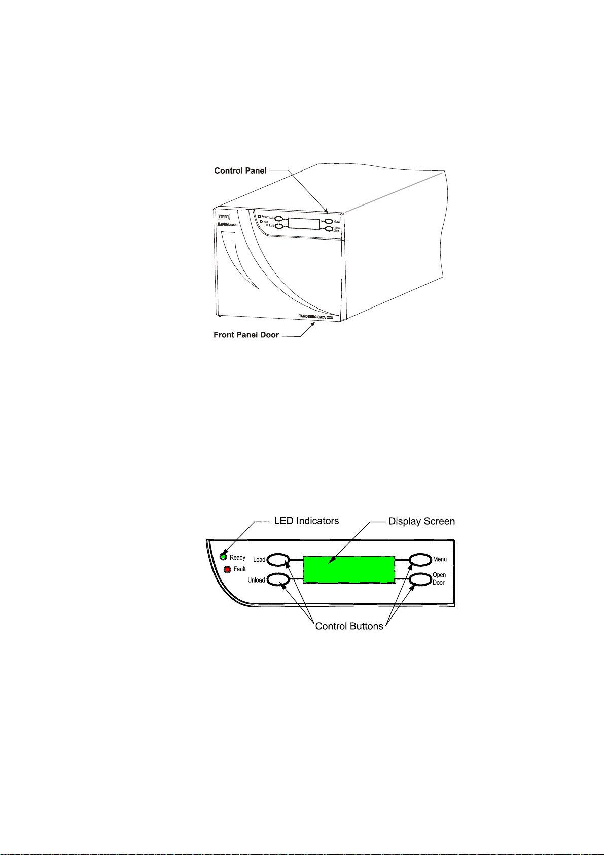
Front Panel
The Front Panel includes the User Control Panel with LCD display and Control
Buttons, LED indicators, and the Front Door Panel.
Control Panel
The control panel presents:
• A backlit green LCD matrix display
• Four control buttons
• Two LED indicators (green and red/amber).
4 Tandberg SLR Autoloader Service and Repair Manual

LCD Display
In various modes of operation, the display panel screens can show you:
• Drive and loader status
• Menu choices, and
• Error messages.
Through most of its operation, the backlit screen displays four 20-character lines of
information. This manual refers to the four text lines of the screen as line 1 through
line 4, moving from top to bottom. You can scroll some screens to greatly expand
the amount of available information. A pointer symbol (θ) indicates additional
options.
Control Buttons
The control buttons let you perform manual tape handling operations, configuration,
and diagnostics:
• The Load button (top left) lets you load tapes from the magazine to the drive.
• The Unload button (lower left) lets you unload tapes from the drive and
return them to the magazine.
• The Open Door button (lower right) releases the door latch after the
completion of any in-process action and when the loader is idle.
• The Menu button (top right) lets you enter menu mode where you can select
configuration options and perform unit diagnostics.
When you enter menu mode, the buttons are re-identified on the display screen to
indicate the different functions they perform under alternate menu levels.
LED Indicators
The green Ready indicator illuminates when the unit is powered up and standing by
to receive instructions. When you start a load, unload, or open door action, the
Ready indicator goes out. The indicator remains illuminated as you enter menu mode
and as you then access the system data. The loader will not remain in a ready state if
you access any other area of the menu mode, and the indicator will then go out.
The red or amber Fault indicator illuminates when the unit experiences a mechanical
fault in the drive or loader robotics. If such a fault occurs, refer to the Error Code
tables in Chapter 6 – Troubleshooting. If that does not clear up the fault, contact
your Technical Support Representative.
Tandberg SLR Autoloader Service and Repair Manual 5
Tandberg Data Chapter 1 - Introduction
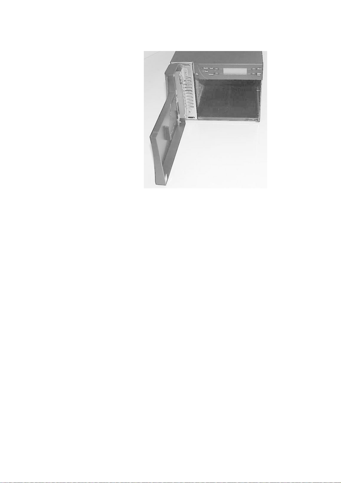
Front Panel Door
The door is opened by a control panel button, with the door latch being released by
the Autoloader robotic mechanism. In order to operate the front door AC power
must be applied. The hinged door swings open to the left, permitting access to the
tape cartridge magazine.
While the door usually remains locked during normal operations, you can open it,
even with a tape in the drive. If you try to open the door with a tape in the drive, the
unit displays a warning message. You can unlock the door or cancel the operation.
6 Tandberg SLR Autoloader Service and Repair Manual
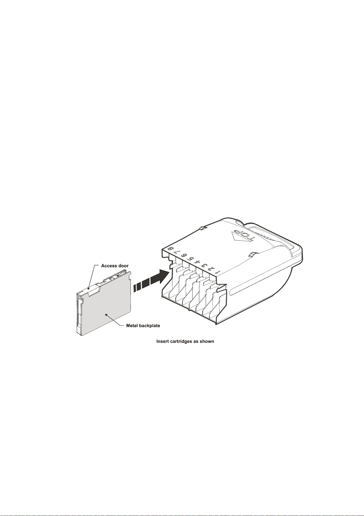
Tape Cartridge Magazine
The 8-cartridge magazine is accessible through the front panel door. The rugged
polymer magazine fits into an alignment guide, which assures precise cartridge
positioning with respect to the loader robotics.
The only correct insertion orientation for the magazine is shown in the photographic
sequence on the next page.
As the magazine moves into its loader compartment, it should move inward until it
snaps into place. (The two chassis metal detents snap into the magazine slots in its
top surface). The magazine locks into position when you close the front door panel.
Note: The SLR Autoloader is shipped with a soft vinyl dust cover for use when the
magazine is not installed in the loader unit. The cover is contained in the
Accessories Kit box and can be easily slipped over the open end of the magazine.
The SLR Autoloader magazine is shown here:
Tandberg SLR Autoloader Service and Repair Manual 7
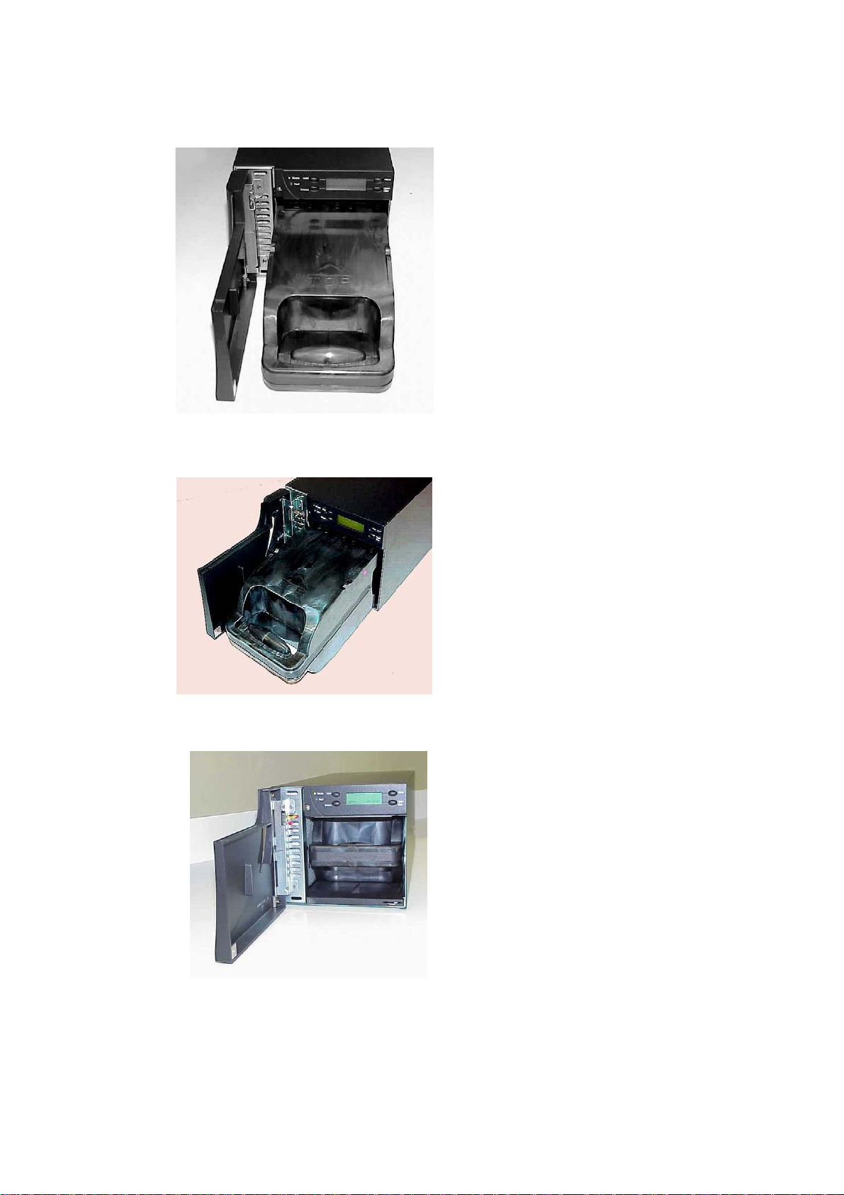
Tandberg Data Chapter 1 - Introduction
LOADING VIEW #1
FRONT VIEW
Proper alignment of magazine prior
to loading it into its bay in the SLR
Autoloader.
LOADING VIEW #2
DIAGONAL SIDE VIEW
Better view of the front end of the
magazine entering its bay of SLR
Autoloader.
LOADING VIEW #3
FRONT VIEW
View of magazine properly locked
into detent position.
8 Tandberg SLR Autoloader Service and Repair Manual
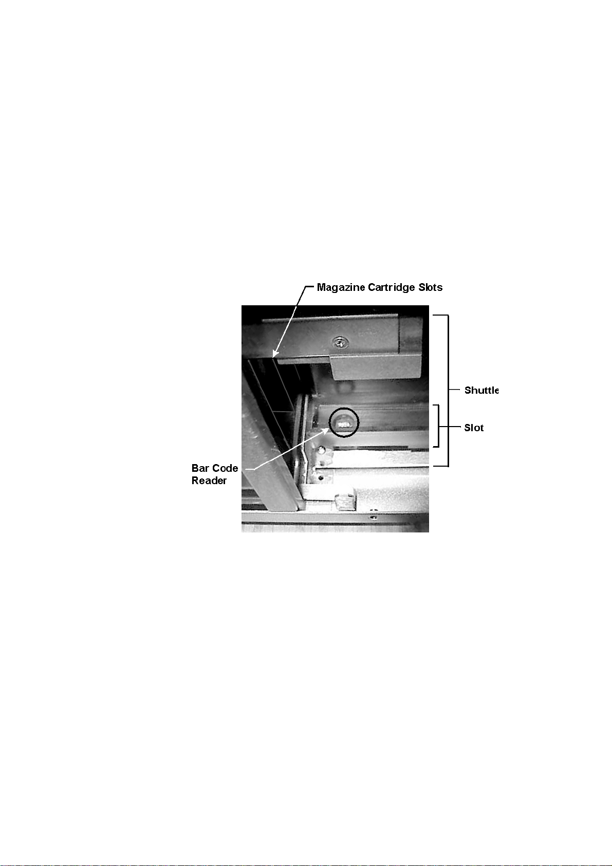
Bar Code Reader
An integrated bar code reader is installed as standard equipment in the SLR
Autoloader. It is an integral part of the robot shuttle assembly and moves with it.
At power up, the loader automatically pulls each cartridge into the robot shuttle to
scan the bar code, and replaces it in the magazine. If the magazine is full, then it
takes approximately 150 seconds (in addition to the normal inventory / calibration
time) to scan all cartridges, since one cartridge can be scanned in 9 seconds, then
returned in equal time to its slot.
Usually hidden by the metal chassis, the bar code reader is located at the leading
edge of the shuttle slot as shown in the following illustration:
Tandberg SLR Autoloader Service and Repair Manual 9
Tandberg Data Chapter 1 - Introduction
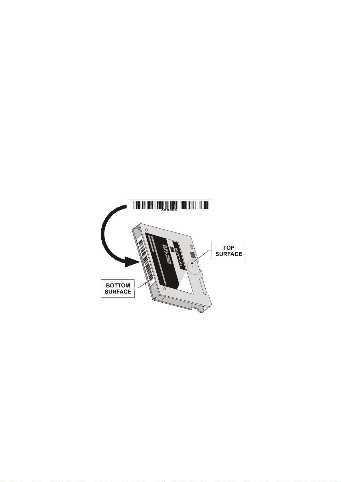
Bar Code Label
The bar code label is encoded with a Code 3 of 9 standard bar code format.
The label for all cartridges consists of six alphanumeric characters: three alpha
characters and three numeric characters. The cleaning cartridge uses CLN as the
alpha characters. For example:
Data cartridge ABC000
DEF123
Cleaning cartridge CLN000
CLN123
Note: You should enable the Enable Check Char option for the most reliable bar
code reader function.
Position the label centrally on the cartridge spine with the six alphanumeric
characters aligned with the cartridge’s base plate.
Ordering Bar Code Labels
You should order additional bar code labels directly from Tandberg Data. Tandberg
bar code labels are made of a mirror-like substrate with special reflectivity, bar
widths, and other characteristics.
Caution: Do not substitute any other bar code labels. They will be unreadable.
See Appendix B – Spares/Accessories for part number information.
10 Tandberg SLR Autoloader Service and Repair Manual

Calibrating the Bar Code Reader
To calibrate the bar code reader, do the following:
1. Insert a cartridge in Slot 2 of the SLR Autoloader. Make sure the cartridge has a
bar code label that is:
• Tandberg approved for SLR Autoloader
• Clean
• Properly positioned on the cartridge.
2. Power up the Autoloader.
3. Press and hold down the
Menu button while you press and release the Load
button.
4. Continue holding down the
Menu button until the READY light turns off. This
will take abt. 10 seconds.
5. From the DIAGNOSTICS menu, scroll down to and select Barcode Calibration.
The SLR Autoloader fetches the cartridge from Slot 2 and moves the cartridge
back and forth across the bar code reader sensor.
It displays the upper and lower values as it progresses through the calibration
and then displays one of the following:
• If the calibration passes
PASSED
• If the calibration fails or is aborted ABORTED
• If there is no cartridge in Slot 2 NO CARTRIDGE IN SLOT 2
6. If there is no cartridge in Slot 2, exit the DIAGNOSTICS MENU, open the door,
place a cartridge in Slot 2, reinsert the magazine and start the procedure again
from Step 3.
Tandberg SLR Autoloader Service and Repair Manual 11

Tandberg Data Chapter 1 - Introduction
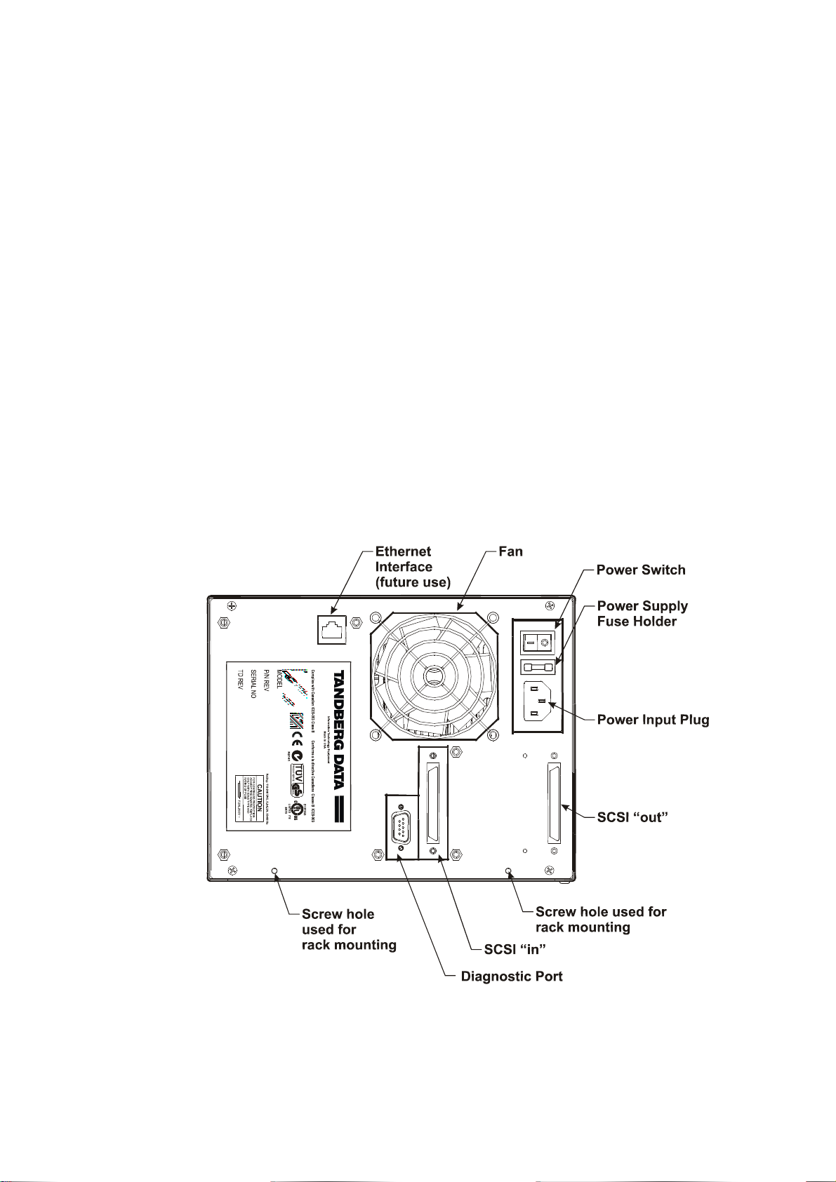
Rear Panel
The rear panel includes eight mechanical devices that relate to bus communication,
firmware upgrading and troubleshooting, device cooling, and line power. Bus
communication between the SCSI Bus connector and the Host adapter occurs
through SCSI Bus connectors (see SCSI In and SCSI Out). The Diagnostic Port
provides sequence information, diagnostic test results and firmware updates. Line
power is supplied and monitored after its circuit is opened by the Power Input Plug,
Power Supply Fuse (in its holder) and the Power Switch. The Product Information
Label includes Model and Serial numbers and cautionary information.
Note: The two empty screw holes on the bottom of the panel are intended for use
only if you mount the unit in a rack. If you have ordered the rack mount conversion
kit, the appropriate fasteners used in this location are provided.
Integrated Cooling Fan
The rear panel contains a single forced-air cooling fan, which draws air inward
through the front of the unit and expels it out the back. The fan prevents overheating
of the drive and robotics electronics, the motors, and the power supply.
Since there is no air filter to clean on a regular basis, you should inspect
occasionally for lint or dust buildup and vacuum the area if necessary.
12 Tandberg SLR Autoloader Service and Repair Manual
Power Switch
The power switch is located on the upper right corner of the rear panel. It is a twoposition rocker switch that controls the supply of AC power to the unit:
• To turn the power ON, depress the switch on the 1 side. The LCD display
illuminates.
• To turn the power OFF, depress the switch on the 0 side.
Power Supply
The auto ranging power supply will adjust to the operating voltage range supplied
through the power cable. The nominal range is 110–240 VAC. The power supply is
capable of operating at 50 or 60 Hz without modification. AC power from a properly
grounded outlet is supplied through a line power cable shipped with the SLR
Autoloader.
For more information on line power cables, see the Power Cable section of Chapter
2 – Installation.
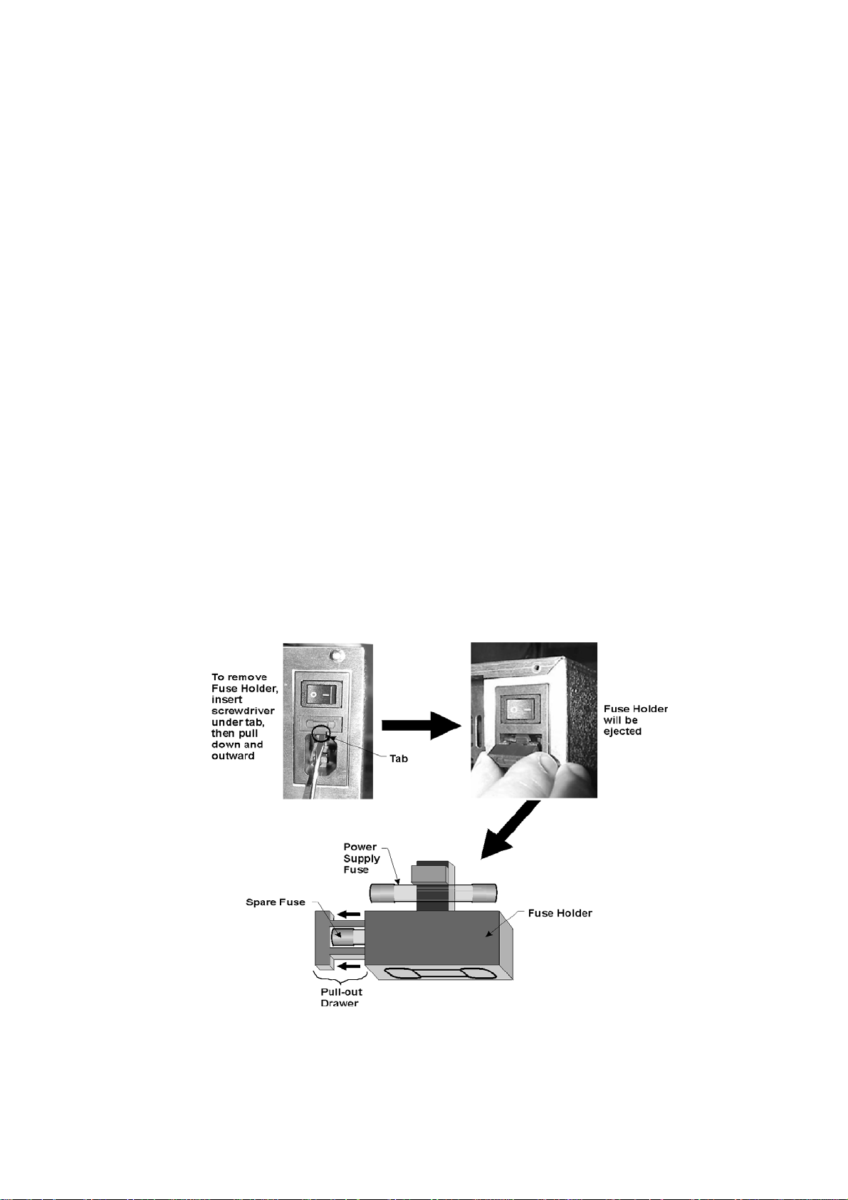
Power Supply Fuse Holder
The power supply fuse holder is located below the power switch as indicated by the
outline diagram on its surface. The procedure for accessing power fuse (and its
spare) is shown below.
Note: Before replacing the fuse, set the Main power switch to OFF and remove the
power cord.
Tandberg SLR Autoloader Service and Repair Manual 13

Tandberg Data Chapter 1 - Introduction
SCSI Interface Connectors
The SCSI Interface connectors link the internal SCSI bus devices (SCSI drive and
robotic controllers) to the external host adapter. The bi-directional SCSI bus
transfers the SCSI commands and data. To provide this function, there are two 68pin, high density, shielded D-type SCSI Connectors which connect to shielded SCSI
Type P cables. The pair of connectors allows for daisy chaining more than one SLR
Autoloader to a host adapter or other SCSI-compatible device. When only one SCSI
connector is used, the second connector must be terminated using the supplied
LVD/SE dual mode terminator.
Ethernet Port
The Ethernet port is reserved for future use.
Diagnostic Port
The Diagnostic port (RS-232) is used to upload fault analysis data by the service
technician after a fault condition occurs. It is also used to update the firmware in the
controller card’s flash memory.
Embedded Diagnostics
• The SLR Autoloader includes three levels of diagnostics:
• The Power-On Self Test (POST) — Performs several verification and
memory tests when you power on the unit.
• User Diagnostics — Lets you change setup options. Select from front panel.
• Tech Support Diagnostics — Used by Technical Support Engineers to
diagnose faults and service the unit.
14 Tandberg SLR Autoloader Service and Repair Manual

This Page Intentionally Left Blank
Tandberg SLR Autoloader Service and Repair Manual 15

Chapter 2 – Installation
*** READ ME FIRST ***
Tandberg Data has installed a locking pin as a precautionary safety mechanism to
prevent damage to the SLR Autoloader during shipment from the factory. Inserted
from underneath the loader floor, the pin prohibits any lateral movement of the
shuttle assembly by locking it down.
CAUTION!
You must remove
the Shuttle Locking Pin
before powering up the unit
or it will not operate.
See the procedure on the following pages.
Carefully unpack the unit from the shipping container. Save the container and
packing materials in case you need to return the unit to Tandberg Data for repairs.
Review the contents of the shipping container to be sure that all parts were included
in the shipment. A complete package for the SLR Autoloader consists of the
following items:
• A factory-assembled SLR Autoloader unit (black or gray metal box)
containing one cartridge magazine.
Note: The SLR Autoloader contains no cartridges prior to shipment.
• An Accessory Kit Box containing:
⎯1 The Tandberg Recource CD containing this manual.
⎯1 Warranty/Registration Card
⎯2 Line Power Cords: one for USA, one for European power outlets
⎯1 Data Cartridge
⎯1 Cleaning Cartridge
⎯1 SCSI Interface Cable
⎯1 68-pin LVD/SE Terminator.
⎯1 Magazine Dust Cover
Note: If you haven’t done so, remove the locking pin from the SLR Autoloader.
Tandberg SLR Autoloader Service and Repair Manual 16
Tandberg Data Chapter 2 - Installation
Removing the Locking Pin
To remove the locking pin (also called lockdown mechanism), do the following:
1. Make sure that the power cord is disconnected from line power.
2. Place the unit on a table at waist height.
3. Position the unit so that the front panel door is facing toward you.
4. Rotate the unit onto its left side so that the bottom of the unit faces right and
its rear chassis end points away from you.
5. Remove the screw from the locking pin as shown in the following
illustration:
Right Side View with
Chassis Panel
Removed
Locking Pin (Installed)
6. Pull the locking pin out slowly. It should come out easily. If it doesn’t,
Screw
Metal Tab on Loc k in g P in
Right S ide View, R otated 45
Upward with Chassis Panel
Removed
°
remove the magazine and investigate the internal shuttle area through the
front panel door with a flashlight. (See Appendix C for instructions on
opening the door without power.) Make sure that the pin is not bent. If it is,
contact Tandberg Data for instructions on removing the pin or returning the
unit to Tandberg Data for repair or replacement.
7. Save the locking pin (6.6” / 16.8 cm) and its screw (M3x8 Phillips panhead)
in case you must return the unit to Tandberg Data. These two parts must be
installed when shipping the unit back to Tandberg Data.
Tandberg SLR Autoloader Service and Repair Manual 17

Reinstalling the Locking Pin
Note: The locking pin must be reinstalled to prevent damage to the
cartridge shuttle mechanism during transportation.
1. Make sure that the power cord is disconnected from line power.
2. Make sure the shuttle is parked in the home position.
(See the description of the Utilities menu on page xx)
3. Place the unit on a table at waist height.
4. Position the unit so that the front panel door is facing toward you.
5. Rotate the unit onto its left side so that the bottom of the unit faces right and
its rear chassis end points away from you.
6. Remove the magazine to have a better view of the internal shuttle area.
7. Push the locking pin in slowly through the hole on the bottom (now facing
right) through to the hole in the metal rack plate on the top side (facing left).
If you have trouble with this, put your hand inside the shuttle area to guide
the pin.
8. Insert and tighten the screw (M3x8 Phillips panhead).
Installation Procedure
After removing the locking pin and confirming that all package items are present in
the shipment, proceed with the installation procedure.
1. Mounting—Proper placement of a tabletop unit or mechanical installation
into a 19” rack.
2. Cabling—Connecting the unit to AC power and to the host interface and
terminating the buses properly.
3. Software Installation.
Tandberg SLR Autoloader Service and Repair Manual 18

Tandberg Data Chapter 2 - Installation
Mounting Tabletop Units
Tabletop units require no mechanical assembly. Place the unit on a desk, table,
server top, or other stable, horizontal surface with at least 2-inch (5 cm) clearance
behind it to allow free flow of cooling air from the fan.
CAUTION: Make sure the Autoloader stays in a horizontal position while
operating. Do not operate it on its side.
Mounting Rack Units
The compact size of the SLR Autoloader permits the mounting of up to two units in
a single shelf of a standard 19” rack. Both units attach to a rack chassis. The units
are secured to the rack chassis by rear brackets and fastened in place by two
machine screws. The chassis and both units fit within a 4U rack height.
Note: Before mounting the SLR Autoloader(s), you must order a separate hardware
kit for converting the unit(s) from a tabletop to a rack mounted one.
Rackmount Installation Process
1. Add the rack chassis to the rack frame.
2. Fasten one or two SLR Autoloader chassis to the installed rack chassis.
Tandberg SLR Autoloader Service and Repair Manual 19

Installation of SLR Autoloader Rack Chassis into Rack
1. Attach the left support bracket to the left rear rail surface side using two 1032x1/2” screws and two 10-32 nut plates.
2. Attach the right support bracket to the right rear rail surface side using two 1032x1/2 screws and two 10-32 nut plates.
3. Attach the front chassis to the inside surface of the front rack rail using four 1032x1/2 screws (two for each side).
4. Attach the left and right bracket(s) to the outside rear chassis surface using four
10-32x1/2 screws and four10-32 hex nuts (two screws and two hex nuts on each
side).
5. Attach left endcap to outside surface of left front rail by snapping a ball stud into
a retaining clip located on the front chassis mounting flange.
6. Repeat Step 5 for the right endcap.
The rack chassis is now ready to mount the SLR Autoloader unit(s).
Installation of SLR Autoloader(s)
To install a single SLR Autoloader:
1. Attach to either the left or right side: the front filler panel to the chassis using
two screws (M3 x 6mm).
2. Prepare the unit before installation:
• Remove the four screws and four rubber feet from the bottom panel of the
unit
• Remove the SLR Autoloader chassis cover by sliding it rearward.
3. Insert the prepared SLR Autoloader unit into the rack chassis until it is stopped
by the rear-mounting bracket.
4. Secure the unit to this bracket using two screws (M3 x 8 mm).
To install two SLR Autoloaders:
1. Prepare both units as described in Step 2 for installing a single unit.
2. Insert both units into the chassis until they are stopped by the rear mounting
brackets.
3. Secure each unit to its mounting bracket using two screws (M3 x 8mm).
Tandberg SLR Autoloader Service and Repair Manual 20
Tandberg Data Chapter 2 - Installation
Cabling and Interface Connections
Before the SLR Autoloader can be powered up or communicate with the host device
or user applications, the following connections must be made (see the diagram of the
rear panel’s connectors on the next page):
• AC line power
• Select and connect the proper line power cable (from the pair of power
cables sent in the Accessory Kit shipped with the SLR Autoloader) between
the Power Input Plug (see the illustration below) and your line power outlet.
• SCSI bus connection to the host (68 pin LVD or SE).
• Connect the SCSI Cable between the SCSI Out connector of the Host
Adapter to the SCSI In connector of the SLR Autoloader. If the SLR
Autoloader is not being daisy-chained to another device, then connect the
supplied LVD/SE Terminator to the SCSI Out connector.
Power Cable
The power cable is a standard grounding AC cable, which plugs a 3-wire connector
into the rear panel and the other end has a country-specific connector plug that fits
into a reliably grounded AC outlet.
Tandberg SLR Autoloader Service and Repair Manual 21

There are two types of power cables supplied with the SLR Autoloader. They differ
in their cable connectors and length. Each cable has a different terminal ending for
connecting to local line power. The cable length of the USA version is 6.5 feet (2.0
m); the European one is 2.5 m.
To maintain product safety compliance, select the power cord with a suitable
electrical rating that is approved for the country where the product is used. In the
USA, use a UL listed cord; in Canada, a CSA certified cord; and in Europe, use a
Harmonized cord marked <HAR> or a nationally certified cord.
Note: After connecting the SLR Autoloader to your AC source, it is a good practice
to do a test power up of the unit before connecting to the host computer. This will
verify proper initialization and electrical behavior and isolate unexpected conditions
to the host interface. The affirmation that the system is operating properly is the
appearance of the cartridge map on the display panel, along with the green Ready
LED being lit. (See the beginning of Chapter 3 – Operation for an example of a
cartridge map on the display panel.) Power down the unit before connecting to the
host.
Interfaces
The SLR Autoloader is supplied with both single-ended Fast/Wide and LVD Ultra 2
SCSI interfaces. The unit configures automatically to either interface.
The Fast/Wide SCSI interface uses high-density 68-pin connectors. Fast/Wide SCSI
cables and terminators are secured to the connectors by jackscrews.
The drive and the robotics are separate SCSI devices. They require unique SCSI
address because they are daisy-chained on the same bus. The SCSI addresses of the
robotics and drive may be set from the control panel.
In order to connect the unit to a host computer system, the host system must have a
compatible SCSI controller and the appropriate driver software. Call your Technical
Support representative if you have any questions about installing for specific host
systems.
Tandberg SLR Autoloader Service and Repair Manual 22

Tandberg Data Chapter 2 - Installation
Interface Cable Specifications
The SLR Autoloader is a high-performance system. To avoid degradation of
performance, any additional or replacement cables you use should likewise be of the
highest quality. The detailed requirements for SCSI cables are set forth in ANSI
X3.131-1994. All SCSI cables used with the SLR Autoloader should meet the
following requirements:
• Shielded or double-shielded, as required to meet EMI specifications
• Nominal characteristic impedance is 90 single-ended and 132 ohms
differential
• Cables of different impedance should not be used together
• Maximum cable lengths as follows:
SE/Fast/Wide Bus LVD Fast Ultra 2 Bus
To Host
34.4 ft
10.46 m
Total
39.4 ft
12 m
5 ft
1.54 m
To Host Total Internal
4.8 ft
1.46 m
9.8 ft
3 m
5 ft
1.54 m
Note: This equipment has been tested for electromagnetic emissions and immunity
using good quality shielded cables. The use of unshielded cables, poor quality
cables or other variances from good practice may result in non-compliance with
national and international rules and degraded performance.
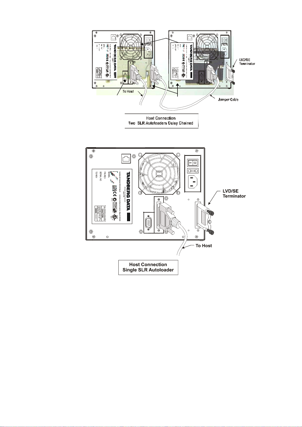
Interface Cable and Terminator Installation
An LVD/SE terminator is supplied with your unit, packaged in the accessory kit
bag.
This terminator must be installed onto the device used at either end of a SCSI bus,
such as the first or last device along a daisy-chain, or as a single SCSI peripheral.
Usually, the host computer’s SCSI interface is at one end of the bus and terminated,
so the question is whether the SLR Autoloader or another device is the last device
on the bus.
On the rear panel of the unit, the incoming SCSI bus is connected to the left SCSI
connector and the terminator or the outgoing SCSI bus is connected to the right
SCSI connector (see the illustration on the next page).
To properly cable the drive, do the following:
1. Make sure the unit and the host computer are powered down.
2. Make sure that your host system has appropriate SCSI interface card or cards
and software drivers installed. The interface card should use Fast/Wide or
Ultra/Wide SCSI, single-ended or low voltage differential (LVD). All models of
the SLR Autoloader are equipped with a LVD/SE Wide SCSI interface. Be sure
to use the same type of SCSI hardware consistently throughout your
configuration.
3. Use only the SCSI terminator supplied with the SLR Autoloader. It should be
one of two available models — either with or without an LED indicator light.
See the following illustration.
Tandberg SLR Autoloader Service and Repair Manual 23
68-Pin High Density Male Connector
LED Light
Thumb Screw Pole
4. If the SLR Autoloader is the only SCSI device you want to connect to the
interface card, connect the cable from the interface card to the incoming SCSI
connector, attach the terminator to the outgoing SCSI connector, then skip to
step 6.
5. If you have two or more additional SCSI devices to connect to the interface card,
your SLR Autoloader must be connected in daisy-chain fashion. That means
that the cable from the interface card must be connected to the incoming SCSI
connector of the first SCSI device, the cable from the outgoing connector of the
first device must be connected to the incoming connector of the second SCSI
device, and so on. You can connect them in any order. The terminator must be
attached to the outgoing SCSI connector of the last device in the chain.
6. Make sure that each cable you use meets the specifications listed earlier in this
chapter.
Tandberg SLR Autoloader Service and Repair Manual 24

Tandberg Data Chapter 2 - Installation
7. Be sure not to exceed the maximum bus length of the entire SCSI bus. The
internal SCSI bus length for the SLR Autoloader is 5.0 feet (1.54 m) including
all cabling and trace lengths. Refer to the manuals for the other SCSI devices to
determine their internal SCSI bus lengths.
Software Installation
The SLR Autoloader comes completely equipped with all necessary on-board
firmware pre-installed at the factory.
You must install and set up the host software necessary to communicate with the
SLR Autoloader that is obtained from a third-party vendor. Set up this software so
that the communication protocol properly transmits between the host adapter and the
SCSI devices of the SLR Autoloader.
Tandberg SLR Autoloader Service and Repair Manual 25

Chapter 3 – Operation
L
System Power-Up
With mechanical installation and electrical connection complete, turn on the AC
power switch. At power-up, for the first three seconds, the unit performs a sequence
of diagnostic tests called Power-On Self Tests (POST). These include: a ROM CRC
check, a RAM test, and a CPU test. As the tests are completed, the control panel
displays a sign-on message and the robotics firmware version number.
After successful completion of the POST sequence, the system performs a series of
initialization functions. The first row of text, Line 1, shows the function currently in
process.
When the unit completes initialization functions, the Default screen appears:
A ‘C’ indicates cleaning
Line 1
ine 4
Idle
Map: 1__456_8 AC
slot occupied when
cleaning is enabled If
enabled, map only
shows 7 slots.
An ‘A’ indicates that
Autoclean is enabled
• Line 1 shows the status of the tape loader mechanism and drive in combination.
When the loader is moving, messages describing the activity (such as Fetching,
Taking Inventory, etc.) appear here. Line 1 also reports the drive status as Active
during read/write operations or Ready when a tape cartridge has been inserted
but is not in motion. When the unit ejects a cartridge from the drive, Ejected
appears at line 1.
• Line 2 shows a cartridge map of the magazine. A number indicates a slot
occupied by a cartridge. An underscore line indicates an empty slot.
• Line 3 shows the six alphanumeric characters of bar code label on the cartridge
in the drive.
• Line 4 shows an activity bar if either the drive or loader is active. The line is
blank when both are idle. This line may alternately display a warning if a drive
cleaning has failed.
Tandberg SLR Autoloader Service and Repair Manual 26

Tandberg Data Chapter 3 - Operation
Selecting the Control Panel Display Modes
After normal startup, the Default Screen appears without operator or host
intervention. Several display modes appear on the display panel screen. To view the
Main Menu, press the Menu (top right) control button on the Control Panel.
The following illustration shows the hierarchical organization of the menu tree of
the SLR Autoloader menus and menu options. The available menu options can vary
according to the specific SLR Autoloader model or firmware revision level.
The SLR Autoloader Menu Map
Takes you back to
SYSTEM DATA EXIT
the default screen
Loader Options
Unload Mode
Numbering Base
Autoclean *
Loader Mode
Sequential Mode **
Baud Rate
Enable Barcode
Enable Chk. Char. #
Serial Number
Cleaning Slot
SCSI Options
Loader SCSI Id.
Drive SCSI Id.
Loader Parity
Vendor Id.
Product Id.
Negotiating Mode
Transfer Rate
Mode Pg. 1F Length
TUR Reporting
Init Elem. Status
Unit Attn. Reporting
SCSI Mode
Cartridge Map
Drive Info
Drive Type
Firmware Id.
Serial Number
Firmware Revision
Fetch Retries
Stow Retries
Fetch Count
Time Since Clean
Power On Time
SETUP UTILITIES
AUTOLOADER
Unload Mode
Numbering Base
Auto Clean *
Loader Mode
Sequential Mode **
Baud Rate
Enable Barcode
Enable Chk. Char. #
Serial Number
Cleaning Slot
SCSI
Loader SCSI Id.
Drive SCSI Id.
Loader Parity
Vendor Id.
Product Id.
Negotiating Mode
Transfer Rate
Mode Pg. 1F Length
TUR Reporting
Init Elem. Status
Unit Attn. Reporting
SCSI Mode
* Displayed only if the Cleaning Slot is enabled.
** Displayed if selected on the Loader Mode option
# Displayed if Enable Barcode is selected
MAINTENANCE
Park
Clean Drive *
Save Configuration
Flash Loader
Download Config.
Set Defaults
Pass Thru
Reboot Module
DIAGNOSTIC
System Cycle
Cartridge Cycle
Drive Test
Barcode Reader Test
SECURITY
Set Password
Tandberg SLR Autoloader Service and Repair Manual 27

Navigating Through the Menu Map
From the Main Menu screen, you can access three submenus: System Data, Setup,
and Utilities. Access the Main Menu Screen from the Default Screen.
System Data Submen u
BACK
SELECT
AUTOLOADE R BAC K
SCSI
Setup Submenu
Main Menu Screen
SYSTEM DATA EXIT
SET UP UTILITIES
Press on the control button associated
with its menu option, either to display a
submenu or to initiate its labeled function.
Default Screen
Idle
Map : 1__3456_8 AC
MAINTENANCE BACK
DIAGNOSTIC SECURITY
Utilities Submenu
Entering the Menu Mode
While viewing the Default screen, press the upper right control button labeled Menu
to change the display to the Main Menu screen. After doing so, you will be provided
three menu options: the SYSTEM DATA menu, the SETUP menu, the UTILITIES
menu and an Exit function. To enter one of these three menus, press the nearest
control button.
Exiting the Menu Mode
If viewing the Main Menu screen, you can exit the menu mode by pressing the
upper right control button associated with the menu option labeled Exit.Otherwise,
if you are viewing one of the three menus or their submenus, then continue to press
on the control button associated with the menu option labeled
Menu screen is displayed. At this time, press
Menu control button to return the
Back until the Main
display to the Default screen.
System Data Menu
The System Data menu options contain the values assigned during device setup
through the identically-named option in the Setup menu’s Autoloader and SCSI
options. Besides the Setup menu options there are additional menu options data
stored in this menu’s fields (see The SLR Autoloader Menu Map earlier in this
chapter). The descriptions of each System Data menu option that contains a value
from the Setup menu options are discussed in Chapter 4 – Configuration.
Tandberg SLR Autoloader Service and Repair Manual 28

Tandberg Data Chapter 3 - Operation
Autoloader Options
The number of possible values for each Autoloader Option setting varies among the
entire Autoloader Option list. All of these values for each menu option of the
Autoloader Options menu are provided on the next page.
Autoloader Options Menu Legend:
[ ] = Example of a default setting for this menu option.
(##) = Number of selectable values for this menu option.
Unload Mode [= Implicit]
(2)
Implicit, Explicit
Numbering Base [= One Base]
(2)
One Base, Zero Base
Auto Clean* [=
Disabled] (2)
Disabled, Enabled
* Displayed only if Cleaning Slor Selected
Loader Mode [= Random]
(2)
Random, Sequential
Sequential Mode* [= Normal]
(2)
Normal, Recirculate
* Displayed if selected in Loader Mode
Baud Rate [=
115.000] (7)
2400; 9600; 19200; 38400; 57600 and 115200
Enable Barcode [= Disabled]
(2)
Disabled, Enabled
Enable Check Char* [= Enabled]
(2)
Disabled, Enabled
* Displayed only if Enable Barcode is selected
Set Serial Number [ None]*
(0)
* There is no value preset for this menu option.
Cleaning Slot [= Disable]
(2)
Disabled, Enabled
Tandberg SLR Autoloader Service and Repair Manual 29

SCSI Options
The number of possible values for each SCSI Option setting varies among the entire
SCSI Option list. Here is a list of all of them for each menu option of the SCSI
Options menu:
SCSI Options Menu Legend:
[ ] = Example of a default setting for this menu option.
(##) = Number of selectable values for this menu option.
Loader SCSI ID [= SCSI ID 4]
(16)
SCSI ID 0 to SCSI ID 15
Drive SCSI ID [= SCSI ID 5]
(16)
SCSI ID 0 to SCSI ID 15
Loader Parity [= Enabled]
(2)
Disabled, Enabled
Vendor ID [=
TANDBERG] (3)
TANDBERG, OVERLAND and Vendor Unique
Product ID [=
SLR AUTOLOADER] (3)
SLR AUTOILOADER, LXB and Vendor Unique
Negotiation Mode [= Do Not Initiate]
(2)
Do Not Initiate, Initiate
TransferRate [= Sync. 10MB/sec]
(3)
Async. Only, Sync. 5 MB/sec and Sync. 10 MB/sec
Mode Page 1F Length [= Short (0x0E)]
(2)
Short (0x0E), Long (0x12)
TUR Reporting [= Standard]
(2)
Standard, Custom
Init Element Status [= No Inventory]
(3)
Force Label Scan, Force Inventory
and No Inventory
Unit Attn. Reporting [= All]
(2)
One, All
SCSI Mode [=
SCSI-2] (2)
SCSI-2, SCSI-3
Tandberg SLR Autoloader Service and Repair Manual 30

Tandberg Data Chapter 3 - Operation
Cartridge Map
When this option is selected, the operator may schroll through a list of all 8
magazine slots and the drive. For each slot and for the drive, line 3 on the display
will indicate if the slot / drive has a cartridge or not. If the Barcode scan is enabled,
the text from the barcode label is displayed.
Drive Info
The SCSI Drive communicates its Product ID (alphanumeric string), Firmware ID
(alphanumeric string), and Serial Number (factory assigned alphanumeric string) to
the SLR Autoloader firmware. When this option is selected, the operator may
schroll through a list containing this information.
Firmware Revision
This option displays the Autoloader FW revision.
Fetch Retries
Displays for each slot and for the drive, the number of cartridge fetch retries.
Stow Retries
Displays for each slot and for the drive, the number of cartridge stow retries.
Fetch Count
Displays for each slot and for the drive, the number of cartridge fetches.
Time Since Clean
Displays the drive run time since the last successful cleaning operation were
performed.
Power On Time
Displays the Power on Time for the loader.
Tandberg SLR Autoloader Service and Repair Manual 31
Setup Menu
The Setup Menu options are described in more detail in Chapter 4 – Configuration.
The Autoloader Setup Submenu
SYSTEM DATA EXIT
SETUP UTILITIES
A
Option Settings
Unload Mode Implicit
Numbering Base One Based
AutoClean Disabled
Loader Mode Random
Sequential Mode Normal
Baud Rate 115,200
Enable Barcode Disabled
Enable Check Char Disabled
Serial Number <xxxxxxxxxx>
Cleaning Slot
UTOLOADER SUBMENU
Explicit
Zero Based
Enabled
Sequential
Recirculate
57,600
38,400
19,200
9,600
2,400
Auto
Enabled
Enabled
Disabled
Enabled
Default settings
display in italics
Displays if cleaning
slot is selected
Displays if selected
in Loader Mode
Displays if Barcode
option is enabled
Tandberg SLR Autoloader Service and Repair Manual 32
Tandberg Data Chapter 3 - Operation
The SCSI Setup Submenu
SYSTEM DATA EXIT
SETUP UTILITIES
SCSI S
Option Settings
Loader SCSI ID SCSI ID 0 to
Drive SCSI ID
Loader Parity Disabled
Product ID SLR AUTOLOADER
Vendor ID TANDBERG
Negotiation Mode Do Not Initiate
Transfer Rate Asynch Only
Mode Pg 1F Length Short (0x0E)
TUR Reporting Custom
Init Elem Status Force Label Scan
Unit Attn Report One
SCSI Mode SCSI – 2
UBMENU
SCSI ID 15
SCSI ID 4
SCSI ID 0 to
SCSI ID 15
SCSI ID 5
Enabled
LXB
Vendor Unique
OVERLAND
Vendor Unique
Initiate
Sync
5 MB/sec
Sync 10 MB/sec
Long (0x12)
Standard
Force Inventory
No Inventory
All
SCSI – 3
Default settings
display in italics
Tandberg SLR Autoloader Service and Repair Manual 33
Utilities Menu
The Utilities Menu options are described in detail in Chapter 4 – Configuration.
The Utility Menues
SYSTEM DATA EXIT
SETUP UTILITIES
AINTENANCE SUBMENU
M
Option Settings
Park Select this option
Clean Drive Select this option
Save Config Select this option
Flash Loader Select this option
Download Config Select this option
Set Defaults Select this option
Pass Thru Select this option
Reboot Module Select this option
Option Settings
System Cycle Select this option
Cartridge Cycle Select this option
Drive Test Select this option
Barcode Reader
Test
Option Settings
Set Password Password: <0000>
Select next or Exit
Select next or Exit
Select next or Exit
Select next or Exit
Select next or Exit
Select next or Exit
Select next or Exit
Select next or Exit
Select next or Exit
Select next or Exit
Select next or Exit
Select this option
Select next or Exit
Displays if cleaning
slot is selected
DIAGNOSTICS SUBMENU
Used by Technical
Support Engineers
SECURITY SUBMENU
Tandberg SLR Autoloader Service and Repair Manual 34

Tandberg Data Chapter 3 - Operation
Autoloader Operation Modes
The autoloader has two operating modes, random mode and sequential mode.
Random mode is the factory default operation mode.
Random Mode
When the loader is operating in random mode, the host computer controls the drive
and the loader robotics individualy through two separate SCSI Id’s. The host can
move cartridges around between magazine slots and between the magazine and the
drive.
Sequential Mode
The purpose of sequential mode is to emulate operator assisted backup over multiple
tapes. When one tape is full and unloaded by the host, the loader robotics will
automaticly replace it with the next cartridge in the cartridge set. This feature can
allow users with single drive backup systems to replace the drive with a loader and
automate their backup routines.
In sequential mode the loader operates with sets of cartridges. A cartridge set,
consist of all cartridges starting with the first cartridge in the magazine or the first
cartridge after an empty magazine slot. The set is ending with the last cartridge in
the magazine or with a cartridge in front of an empty magazine slot.
Example: If the magazine has cartridges in slot 1, 2 and 3 and in slots 5, 6, 7 and 8,
the magazine contains two cartridge sets separated by the empty slot 4.
A full magazine contains one set of 8 cartridges. (7 cartridges if the Cleaning slot is
enabled.)
When the loader is set in Sequential mode, the host can only control the tape drive.
The loader will respond normally to an Inquiry and a Request Sense command, but
will return a check condition on all media changer type commands. The Sense Key
will be set to 02h (Not Ready) and the Asc / Ascq will be 04h/8Eh (Logical unit Not
Ready, Sequential mode).
Chapter 4 – Configuration. describes how the loader can be set in sequential mode.
The Sequential mode has two sub modes, normal or recirculate sequential mode.
Tandberg SLR Autoloader Service and Repair Manual 35

Sequential Operation
A sequential operation is started when a cartridge from a set is loaded into the drive
using the front panel Load button. Any cartridge in a set can be selected as the first
cartridge and the sequential operation will run until the last cartridge in the set has
been unloaded from the drive. (Normal sequential mode).
In a backup situation, the host will write data to the cartridge until it is full. The
cartridge will be logically terminated and the host will Unload the cartridge. The
drive will now respond to Test Unit Ready (TUR) commands with Not Ready, No
Cartridge until a new cartridge has been loaded. The loader robotics will, when it
detects that the cartridge has been ejected, move the cartridge from the drive back to
it’s original slot. The next cartridge in the set will then be moved to the drive and
inserted. Once the cartridge is loaded, the drive will respond to a TUR command
with a ready status and the host can continue the backup operation on the new
cartridge.
A restore operation operates the same way. When a tape is read to End of Data, it is
unloaded by the host and the robotics replaces it with the next cartridge in the
sequence.
The sequential operation can be terminated prematurely with the front panel Unload
button. The cartridge in the drive will be ejected and moved back to the magazine.
Note: Before the sequential operation is terminated manually, make sure the backup
operation is completed. If not, the backup will fail and the data on the last tape will
be incorrectly terminated.
Recirculate Sequential Mode
The recirculate sequential mode operates like normal sequential mode with one
exception. When the last cartridge in the set is unloaded from the drive, the
sequential operation will not terminate. The operation will continue with the first
cartridge in the set.
This mode of operation has to be terminated manually with the Unload button on the
front panel.
Tandberg SLR Autoloader Service and Repair Manual 36

Tandberg Data Chapter 3 - Operation
Setting the Write-Protect Switch
Before loading cartridges into magazines, you should set the write-protect switch of
each cartridge to enable or disable data recording.
• To enable data recording, rotate the write-protect switch until it points to the
unlocked icon.
• To disable data recording, rotate the write-protect switch until it points to the
locked icon.
Tandberg SLR Autoloader Service and Repair Manual 37

Cartridge Handling
Inserting Cartridges into the Magazine
Insert cartridges so that access door is facing up and located at the magazine front.
After you insert your cartridges, position the magazine so that the cartridges face
forward and the handle is toward you. Make sure the cartridges latch.
Loading a Cartridge into the Drive
The normal operations of the unit are controlled by storage management software
resident on the host computer. When you must load or unload a specific cartridge
using the control buttons on the front panel, do the following:
To load a cartridge:
1. Press the Load button.
The screen displays a cartridge slot number on line two and the barcode label
text for the cartridge on line three:
▲ CANCEL
SLOT 1
Label = XXX111
▼ SELECT
2. Select the slot number of your choice. The system ignores empty slots. Press the
▲ button to increment and the ▼ button to decrement.
3. Press the SELECT button.
The robot shuttle removes the cartridge from the selected magazine slot and
moves it to the drive.
Tandberg SLR Autoloader Service and Repair Manual 38

Tandberg Data Chapter 3 - Operation
To unload a cartridge:
1. Press the Unload button.
The following screen appears, displaying the slot number of one of the
available, empty cartridge slots on line two:
▲ CANCEL
SLOT 1
▼ SELECT
2. Select the cartridge slot number of your choice. Press the ▲ button to increment
and the ▼ button to decrement.
3. Press the SELECT button.
The robot shuttle removes the cartridge from the drive and moves it to the
selected magazine slot.
Tandberg SLR Autoloader Service and Repair Manual 39

Magazine Handling
You must remove the magazine from the unit in order to insert or remove cartridges.
When inserting cartridges, be sure that the slot you intend to use is not already
reserved in the system map for a cartridge in a drive. The best way to avoid conflicts
is to unload the drive, either through your host computer software or by using the
Unload button on the control panel.
Note: You cannot insert or remove the magazine if the unit is password protected or
locked by host software.
Inserting a Magazine into the Unit
If the magazine door on the front of the module is closed and locked, open it, as
follows:
1. Press the Open Door button.
The magazine door swings open.
2. Slide the magazine through the door opening, with the cartridges protruding
from the front and the molded top arrow facing up.
3. When the magazine is fully inserted, push the door closed until it locks. The
door will not close if the magazine is not fully inserted.
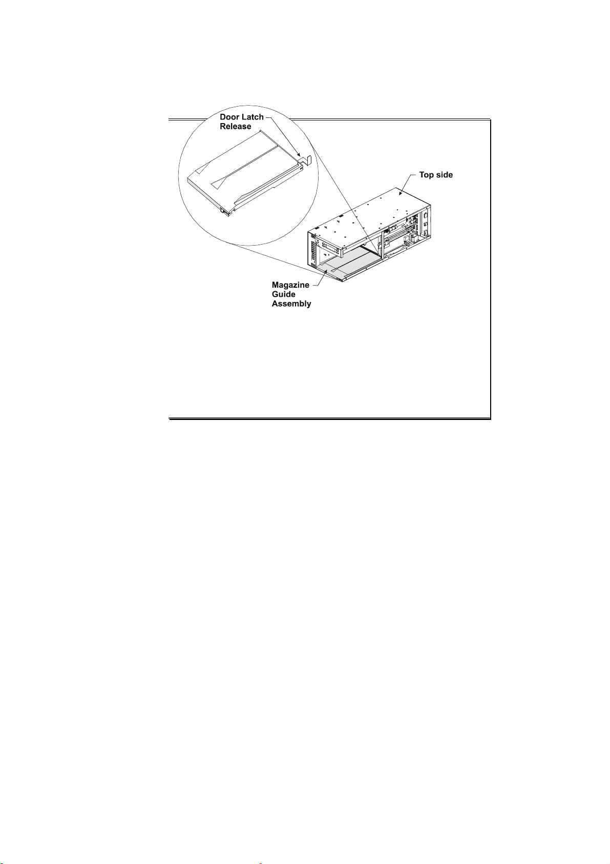
Removing the Magazine
Whenever the front panel door is closed, it is locked in place to prevent tampering or
accidental removal. To remove the magazine, press the Open Door button on the
control panel. After a short delay, the shuttle moves to the Door Latch Release to
activate the door latch, which opens the front panel door.
Tandberg SLR Autoloader Service and Repair Manual 40
Tandberg Data Chapter 3 - Operation
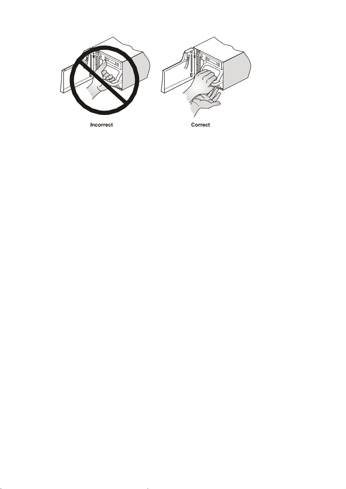
WARNING!
DO NOT push on display panel
when pulling out the magazine.
Using your thumb for leverage
can crack the display panel.
Such damage can lead to
INJURY or ELECTRICAL SHOCK.
The following illustration shows the correct way to remove the magazine from its
compartment.
Tandberg SLR Autoloader Service and Repair Manual 41
Chapter 4 – Configuration
This chapter describes:
• Setting up initial system configuration parameters with individual setup and
utility options
• Entering characters into a menu option using the Control Panel
• Protecting the system with a password.
Before using the SLR Autoloader for the first time, you must set specific
configuration parameters:
• Setup options—Setup menu under Autoloader and SCSI Options submenus
• Utility options—Utilities menu under Maintenance, Diagnostics, and Security
submenus.
Note that if any setup options are changed, the new values will immediately be
saved in Non-Volatile memory. However, some of the options will also require the
loader to be rebooted for the change to tale full effect. If any such options are
changed, the loader will automaticly reboot when exiting from the main menu.
Setup Options
Autoloader Options
Unload Mode — Determines how the loader will react to moves that require a
drive to be in the unloaded state. Setting this value to Implicit indicates that an
unload is implied, causing the loader to issue an unload command to the drive when
necessary. Explicit indicates that the host must explicitly issue an unload to the
drive before issuing a move command to the loader.
Numbering Base— Sets the base for the numbering system. One Based indicates
that all element numbering begins at 1 (Drive 1 and Slots 1 through 8). Zero Based
indicates that the elements begin at 0 (Drive 0 and Slots 0 through 7). This value
affects only the front panel display.
Tandberg SLR Autoloader Service and Repair Manual 42

Tandberg Data Chapter 4 - Configuration
Auto Clean Mode — Enables AutoClean Mode. This option does not display
unless you have selected a cleaning slot.
Loader Mode — Allows the loader to be used as either a random access device or
as a sequential loader device. When set to Random, the host has full control over the
movement of cartridges.
Tandberg SLR Autoloader Service and Repair Manual 43

Sequential Mode — Applies when the Loader Mode is set to Sequential. When
Normal is selected, sequential operation terminates after the last cartridge in the
sequence has been unloaded. A cartridge sequence ends at an empty slot or when the
cartridge in slot 8 has been unloaded. (Slot 7 if Cleaning Slot is enabled)
When Recirculate is selected, operation continues with the first cartridge in the
sequence. This option does not display unless you have selected Sequential Mode in
the Loader Mode option.
Baud Rate — Sets the trace serial port baud rate. Allowable values are:
• 2,400
• 9,600
• 19,200
• 38,400
• 57,600
• 115,200 (Default).
Enable Bar Code — Enables the bar code reader. When the reader is enabled,
the barcode of the cartridge in each occupied magazine slot and in the drive (if any)
will be scanned during the Inventory process.
Enable Check Char — Enables the check sum character to be used to verify the
correctness of each bar code label scan. Does not display unless you have enabled
the bar code reader in the Enable Bar Code option.
Cleaning Slot — If enabled, dedicates slot 8 to cleaning operations.
Note: Do not insert the cleaning cartridge in any other slot than slot 8.
Set Serial Number — The 12-character string of the assigned serial number
entered using the control panel and buttons.
Tandberg SLR Autoloader Service and Repair Manual 44

Tandberg Data Chapter 4 - Configuration
SCSI Options
Loader SCSI ID — Sets the SCSI ID of the loader. Legal values range from 0 –
15.
Drive SCSI ID — Sets the SCSI ID of the drive. Legal values range from 0 – 15.
Loader Parity — Enables/Disables the parity checking for the loader SCSI bus.
Vendor ID — Sets the SCSI Vendor ID. The default Vendor ID is “Tandberg
Data”. Other predefined Vendor ID’s can be selected by scrolling through a list of
choices or enter a unique string by selecting the <Vendor Unique> setting.
Product ID — Sets the SCSI Product ID. The default selection for this option is
SLR Autoloader. Other predefined Product IDs can be selected by scrolling through
a list, or entering a unique string after selecting the <Product Unique> setting.
Negotiation Mode — Determines if SCSI negotiation is initiated by the loader.
Allowable values are Do Not Initiate or Initiate.
Transfer Rate — Defines the SCSI burst transfer rate. Allowable values are:
• Synchronous, 10 MB/sec
• Synchronous, 5 MB/sec
• Asynchronous Only.
Mode Pg 1F Length — Defines the length of the Device Capabilities page
Parameter Length expected by a SCSI Host.
TUR Reporting — Determines how the loader should respond to a Test Unit
Ready command if in Sequential Mode. This option is available only if sequential
mode is active.
Init Elem Status — Determines how the loader should respond to an Initialize
Element Status command. The options are:
• No Inventory
• Force Inventory
• Force Label Scan.
Unit Attn Report — Determines if the loader should stack multiple Unit Attention
responses (ALL) or send only the highest priority Unit Attention response (One).
SCSI Mode — Defines the loader as SCSI-2 or SCSI-3.
Tandberg SLR Autoloader Service and Repair Manual 45

Utilities Options
Maintenance Submenu
Clean Drive — Enables running an installed cleaning cartridge. (Cleaning Slot
must also be enabled in the Setup Menu.)
Park — Enables moving the shuttle assembly to the home position. This option
must be executed before the loader is prepared for transport by insering the Locking
Pin. (See chapter 2, Installation on how to remove and install the Lockin Pin.)
Save Config — Saves all configuration modifications.
Flash Loader — Enables the loader to accept FLASH data through the serial port.
Note: Not used for firmware upgrade via SCSI.
Download Config — Downloads all configuration modifications.
Note: The use of the Save- and Download Config and the Flash Loader options
requires that the operator has access to the LibCenter utility program.
Set Defaults — Stores the default settings for all setup options in Novram.
Pass Thru — Connects drive serial port to loader serial port allowing direct pass
through. Baud rate is fixed at 19,200.
Reboot Module — Performs a soft reboot of the loader without affecting the
drive.
Diagnostics Submenu
This submenu is used by Technical Support Engineers to perform the following
diagnostic tests:
System Cycle — Cycles cartridges through random slots and the drive.
The magazine must be stocked with a minimum of two and a maximum of seven
(six if the cleaning slot is enabled) cartridges to run this test.
Drive Test — Loads a cartridge into the drive and runs a drive Standalone
Diagnostic test. The magazine must be stocked with at least one writeable cartridge
to run this test.
Cartridge Cycle — Cycles cartridges through random slots in the magazine only.
The magazine must be stocked with a minimum of one and a maximum of seven
(six if the cleaning slot is enabled) cartridges to run this test.
Tandberg SLR Autoloader Service and Repair Manual 46

Tandberg Data Chapter 4 - Configuration
Security Submenu
Set Password — Allows you to set a password that can restrict access to the
system through the front panel. If you set the password to a non-zero value, and
press the Load, Unload, or Open Door buttons, the system prompts you for the
password. If you enter the password correctly, the operation continues. If you enter
the password incorrectly, a warning message displays for three seconds and the
operation stops.
These descriptions of the setup options should have made it easier for you to select
the appropriate ones to set for your particular system. The following section will
explain how to change a Setup Option.
Tandberg SLR Autoloader Service and Repair Manual 47

Changing a Configuration Option
These configuration options (such as Setup and Utilities) allow the SLR Autoloader
to support a variety of storage management software and network platforms. The
settings for each option are stored in non-volatile memory inside the unit.
For most applications, you do not have to change the factory default settings. If you
do, follow the procedure outlined below. This section contains descriptions of each
setup option and a summary table of the default settings. If you are uncertain
whether you need to change a setting, contact your Technical Support
representative.
To change a Setup (or Utilities) option:
Note: the procedure for changing a Utilities option is identical to this procedure for
changing a Setup option except that the Utilities menu and its options are accessed
instead of the Setup menu.
1. From the Main menu screen, press the Setup button.
The Setup screen appears, displaying button functions that let you select Loader
or SCSI options or go back to the main menu:
AUTOLOADER BACK
SCSI
2. Press the AUTOLOADER or SCSI button.
A screen similar to the following appears, showing the first item in a list of
Loader or SCSI options:
CANCEL
U n lo a d M o d e
▼ ACCEPT
3. Press the ▼ button to scroll through the list to the option you want.
Each time you press the button, the next option in the list appears on the screen.
As you scroll past the first option, a ▲ button appears in the top left corner. Its
associated button lets you move backwards through the list.
Tandberg SLR Autoloader Service and Repair Manual 48

Tandberg Data Chapter 4 - Configuration
4. From the option you want, press the SELECT button. ▲
A sc reen sim ilar to the follow ing a pp ears, sho w ing the c urren t
value for the selected option:
▲ CANCEL
U n lo a d M o d e
= Im p lic it
▼ ACCEPT
5. Press the ▼ or ▲ button to scroll through the available values.
6. When you’ve displayed the option you want, press the ACCEPT button.
7. Press the CANCEL button to choose another option.
Entering Characters from the Control Panel
To enter characters into any menu option, do the following:
3. Select the appropriate menu option as described in Chapters 3 and 4.
4. Press the SELECT button to display the field data entry screen.
5. In this screen, two opposite facing arrows (▲,▼) are assigned to the left control
panel buttons and a right arrow (►) is assigned to the upper right control button.
When the up and down button is pressed, each button will scroll differently
through the ASCII character set assigned to each character position depending
on where the cursor is currently positioned.
6. Starting with the default cursor position for entering characters, press the ▲
button to move through the character set starting with symbols > numbers (0–9)
> more symbols > alphabet from A to Z. To reverse the scrolling through the
assigned character set, press the ▼ button.
7. To store the selected character, press the ► button on the control panel. This
moves the cursor one character space to the right.
8. Repeat Steps 3 and 4 of this procedure until you have entered all characters.
9. When you have entered the last character, press the DONE button.
The display changes and asks whether to “Save String?”
10. If you made no errors while entering the character string, press the YES button.
If you made an error, press the NO button.
11. Press the appropriate control panel button for your next selection or press BACK
twice to return to the main Menu Screen.
Tandberg SLR Autoloader Service and Repair Manual 49

Default Setup Options
Setup Option Default
Autoloader
Unload Mode Implicit
Numbering Base One Based
Auto Clean Disabled
Loader Mode Random
Sequential Mode Normal
Baud Rate 115,200
Enable Bar Code Disabled
Enable Check Char Enabled
Cleaning Slot Disabled
Set Serial Number _ _ _ _ _ _ _ _ _ _ _ _ (12 spaces)
SCSI
Loader SCSI Bus ID 4
Drive SCSI Bus ID 5
Loader Parity Enabled
Vendor ID TANDBERG
Product ID SLR AUTOLOADER
Negotiation Mode Do Not Initiate
Transfer Rate 10 Mbytes/second Synchronous
Mode Page 1F Length Short (0X0E)
TUR Reporting Standard
Init Elem Status No Inventory
Unit Attn Report All
SCSI Mode SCSI-2
Tandberg SLR Autoloader Service and Repair Manual 50

Tandberg Data Chapter 4 - Configuration
Setting a Password
You can restrict access to the system by setting a password in the Setup options.
When these access codes are set, the Load, Unload, or Open Door buttons will cause
an entry prompt to appear on the screen. The password also restricts access to the
Utilities and Setup menues. The System Data menu has no access restrictions.
When you enter your password correctly, the operation proceeds as normal.
Incorrect entry causes a warning message to appear for 3 seconds before the
operation is terminated.
To set a password:
1. Press the Menu button.
The Main Menu screen appears.
2. Select the UTILITIES menu.
The Utilities menu screen appears.
3. Select the SECURITY menu.
4. Select Set Password.
The password screen appears:
▲ CANCEL
Password: 0
000
► ACCEPT
5. Set the password using the associated control panel buttons:
▲ Increments the number above the cursor (0–9).
► Moves the cursor one character to the right. If the cursor is in
the last position, it reverts back to the first position.
CANCEL Aborts the password operation.
ACCEPT Sets the currently displayed password.
To disable a password:
To disable the password function, set its value to zero.
WARNING: If you set a password, make sure you do not forget it. If you do, it can
only be cleared with assistance from Tandberg Data technical support or by a
qualified service technician.
Tandberg SLR Autoloader Service and Repair Manual 51

This Page Intentionally Left Blank
Tandberg SLR Autoloader Service and Repair Manual 52

Chapter 5 – Maintenance
This chapter shows you how to:
• Use the cleaning cartridge
• Install firmware upgrades.
Using the Cleaning Cartridge
The cleaning cartridge is similar in size and shape to the regular SLR data cartridge.
There are three procedures for using the cleaning cartridge: two manual and one
automatic. Before using any of these procedures, you must install the cartridge into
the magazine correctly.
WARNING: The cleaning cartridge should not be installed in any other slot than
slot #8. An attempt to do so will most likely result in an operation error.
Installing a Cleaning Cartridge
1. Make sure there are no cartridges loaded into the drive.
2. Remove the magazine from the unit.
3. Remove any cartridge present in slot #8.
4. Insert the cleaning cartridge into slot #8.
5. Return the magazine into the unit.
6. Close the magazine door.
After installing the cartridge you can set the cleaning procedure to run manually or
automatically.
Tandberg SLR Autoloader Service and Repair Manual 53

Tandberg Data Chapter 5 - Maintenance
Running an Installed Cleaning Cartridge
Manual Method 1
This method can be used if the Cleaning Slot is disabled in the Setup menu.
1. Install a cleaning cartridge in slot #8.
2. Use the Load button to load the cleaning cartridge into the drive.
3. When the display changes from Drive Ready to Tape Ejected, you can
Unload the cartridge back to the magazine.
Manual Method 2
1. Make sure that Cleaning Slot is enabled in the Setup Menu. (This
dedicates Slot 8 to cleaning operations.)
2. Install a cleaning cartridge in slot #8.
3. Select Clean Drive from the Maintenance section of the Utilities menu.
Automatic Method
Make sure that Cleaning Slot and Auto Clean are enabled in the Setup Menu.
(This allows the loader to automatically load a cleaning cartridge from slot 8
into the drive whenever it needs cleaning.)
Removing the Cleaning Cartridge
1. Determine whether a cartridge is loaded into the drive. If so, unload it.
2. Remove the magazine from the unit.
3. Remove the cleaning cartridge from the magazine.
4. Insert any desired data cartridge into the slot vacated by a cleaning
cartridge.
Note: The Cleaning Slot must be disabled in the Setup meny to make use of
a data cartridge in slot #8.
5. Insert the magazine into the unit.
6. Close the front panel door.
54 Tandberg SLR Autoloader Service and Repair Manual

Installing Firmware Upgrades
The loader FW can be upgraded via the RS232 diagnostic port on the back of the
loader or via the SCSI interface. Before attempting this upgrade, make sure you
have access to a FW Upgrade Utility program for loading the new firmware into the
SLR Autoloader. Tandberg Data recommends an upgrade via SCSI.
Firmware upload via SCSI.
A suitable utility program, FlashIt, and the FW image file, can be downloaded from
the Tandberg Data webb site http://www.tandberg.com/. The program is available
for DOS, WIN95/98 and for Windows NT. The FW immage file shall be named
AS00xxxx.bin were xxxx is the FW revision number. (Example: AS000302.bin for
FW revision 03.02)
Note: Read this entire procedure before you perform an upgrade.
1. Install the FlashIt utility, suitable for your operating system, on your computer
or server were the loader is connected.
2. Make sure the computer has detected the loader.
3. Some operating systems, like Win NT, may require that all backup services
started by the Backup SW is stopped before the FlashIt utility is started.
4. The appropriate FW file must be located on the same directory as the FlashIt
utility.
5. Start the FlashIt utility and follow the instructions in the program.
6. As the Download Utility begins data transfer, the SLR Autoloader displays,
alternately, the following two messages:
While erasing old firmware:
Flash Firmware
SCSI Update:
Erasing
Sector x of y
While programming:
Flash Firmware
SCSI Update
Programming
Sector x of y
Tandberg SLR Autoloader Service and Repair Manual 55

Tandberg Data Chapter 5 - Maintenance
7. When all sectors of the flash has been erased and programmed, the SLR
Autoloader will display the following messages.
After firmware is downloaded:
Flash Firmware
SCSI Update
Checking CRC
When programming is complete and the Autoloader reboots:
Flash Firmware
Update Successful
Please Wait While
Loader Reboots
8. Compare the Firmware ID that appears on the display panel as the unit reboots
to the Firmware ID that was present at the beginning of this procedure to verify
that the correct FW version is programmed.
Firmware upgrade via the serial port.
A new firmware may also be uploaded via the serial, debug port at the back of the
loader. To use this option the operator needs a special serial debug utility program.
Contact your Technical Support Representative for assistance if you need to use this
option.
Possible Upgrade Problems
If a power loss or a failure occurs while you are upgrading firmware, the firmware
might be corrupted. To recover from a FW upgrade failur like this, a new download
has to be performed using the serial download tool. Contact your Technical Support
Representative for assistance.
WARNING!
Loss of power while downloading
new firmware may permanently
damage the flash memory chips.
56 Tandberg SLR Autoloader Service and Repair Manual

Chapter 6 – Troubleshooting
The Fault Screen
When the SLR Autoloader detects a fault condition, the red/amber Fault LED
illuminates and one of the fault screens, shown below, appears on the control panel:
Fault Code: 3013
Drive Fetch Failed
REBOOT PASS THRU
Fault Code: 2912
Unknown Tape Type
EXIT PASS THRU
In these examples, Line 1 displays a fault code number to help you or your technical
support representative diagnose the problem. Line 2 gives a description of the
condition. Line 3 may for some errors display additional error information. Line 4
displays available corrective actions that you can start with a press of the associated
control panel button.
If the corrective action is Reboot, a hard error has occurred and the loader has to be
rebooted to recover.
If the corrective action is Exit, a soft fault has occurred and the loader may continue
to operate correctly once the user presses the assosiated control button.
The Pass Thru option can be used by a service engineer to gain access to the drive
diagnostic port through the loader.
When a fault condition occurs, identify the problem using the displayed error codes
and follow the suggested actions. Current error codes are listed in the next section.
Tandberg SLR Autoloader Service and Repair Manual 57

Tandberg Data Chapter 6 - Trobleshooting
Error Codes
The error codes are listed in numerical sequence by their Fault Symptom Code (FSC)
in the tables that follow. If a persistent error condition prompts you to call your
Technical Support representative, be sure to furnish the code information to help
identify the problem.
System Error Codes
FSC Display Message Description Source of Failure Suggested Action
0101 Unused Interrupt An unused interrupt
was detected.
0102 Enqueue'g a Null Ptr NULL pointer detected
in message queue.
Trace Error Codes
FSC Display Message Description Source of Failure Suggested Action
0201 Trc COMM Open Error Unable to open Trace
com port.
0202 Drv COMM Open
Error
Unable to open Drive
com port.
Robotics Assembly Press the REBOOT
button on the Control
Panel.
Robotics Assembly Press the REBOOT
button on the Control
Panel.
Novram Error Codes
FSC Display Message Description Source of Failure Suggested Action
0301 Novram Init. Error Could not initialize the
configuration area of
the flash device.
0302 Novram CHKSUM
Error
0303 Novram Update Error Could not update the
Checksum error
detected in the
configuration area of
the flash device.
configuration area of
the flash device.
Robotics Assembly Press the REBOOT
button on the Control
Panel.
Press the Exit button and
continue.
Press the REBOOT
button on the Control
Panel.
Printf Error Codes
FSC Display Message Description Source of Failure Suggested Action
0401 Invalid Display Line Attempting to write to
a non-existent display
line (Firmware Error).
Robotics Assembly Contact Tandberg Data
for new firmware.
Flash with new firm-ware.
See Installing Firmware
Upgrades in Chapter 4.
58 Tandberg SLR Autoloader Service and Repair Manual

SCSI Error Codes
FSC Display Message Description Source of Failure Suggested Action
1001 SCSI Firmware Error SCSI Process
detected an
unexpected error
condition.
1002 SCSI FIFO Empty SCSI Controller FIFO
is empty.
1003 SCSI FIFO Error SCSI Controller FIFO
should be empty.
1004 SCSI Gross Error SCSI Controller
detected a
catastrophic error
condition.
1005 Illegal SCSI Cnt Cmd SCSI Controller did
not recognize the
command.
1007 SCSI Invalid Element SCSI Process
detected an
unexpected error
condition.
1009 SCSI Invalid Int SCSI Controller
posted an unexpected
interrupt.
1020 No Active Command
1021 SCSI Invalid Request
1022 SCSI Invalid
Semaphore
1023 SCSI Invalid State
1024 SCSI Invalid Ctl Msg
1025 Overlapped Ctl Cmds
1026 Overlapped Ctl Msgs
SCSI Process
Queuing Error
SCSI Process
Queuing Error
Robotics Assembly
Faulty SCSI cabling
or
Robotics Assembly
Robotics Assembly
Press the Exit button and
continue.
Tandberg SLR Autoloader Service and Repair Manual 59

Tandberg Data Chapter 6 - Trobleshooting
Control Process Error Codes
FSC Display Message Description Source of Failure Suggested Action
2001 Ctl Invalid Command An invalid command
was received by the
control process.
2004 Loader Not Ready Command received
while Loader was not
ready.
2005 SCSI Id Not Set An attempt to set the
drive SCSI ID failed.
2008 Illegal Move While attempting to
perform a MOVE
operation, the source or
destination locations
were in the wrong state
(FULL or EMPTY).
Also occurs if MOVE is
attempted with an invalid
cartridge map.
2009 Door Open A command was
received while door was
open.
200A Menu Mode A command was
received while unit was
in Menu mode.
200C Cart Unaccessible An attempt was made to
fetch a cartridge from a
drive not in ejected
state. Applies when
system is config-ured for
explicit unloads.
200D Drive In Error An attempt was made to
access a drive in an
error state.
200F Removal Prevented An attempt was made to
access a drive in the
Prevent Media Removal
state.
2040 Invalid Ctl Msg An illegal message type
code was received. Can
be the result of receiving
a NULL type code, a
status code without a
command being active,
or a command code
while a command is
currently active.
Robotics Assembly Contact Tandberg Data
for new firmware.
Flash with new firm-
ware. See Chapter 4.
Software or operator
procedure error
Drive or robotics
assembly error
Software or operator
procedure error
Drive or Robotics
Assembly
Software or operator
procedure error
Robotics Assembly Press the REBOOT
Press the REBOOT
button on the Control
Panel.
Replace the SCSI drive
or check the firmware
level.
Press the REBOOT
button on the Control
Panel.
Close the door.
Exit the Menu mode
Check host software for
proper function.
Reboot the system.
Replace the drive.
Reboot the system.
Check host software.
button on the Control
Panel.
60 Tandberg SLR Autoloader Service and Repair Manual

Control Process Error Codes (Continued)
2050 No Free Queues The system could not
allocate a free queue.
2610 BREAK Detected
2611 DACI Locked
2612 DACI Busy
2613 Drive Busy
2614 Illegal CDB
2615 Illegal Parameters
2617 Unknown Command
2618 DACI Poll Error
2619 Illegal Data
267F Status Timeout No response from drive.
Unexpected status
returned from drive.
Drive Assembly Press the REBOOT
button on the Control
Panel.
Drive Selftest Error Codes
FSC Display Message Description Source of Failure Suggested Action
2910 Drive Sensor Error Tape positioning error
occurred during load.
2911 Runout Cartridge The tape on the
cartridge has been run
off the spool.
2912 Unknown Tape Type The drive does not
recognice the tape type.
2917 W rite Protected Cart. The tape cartridge is
write protected
203C Illegal Tape Type The drive can not write
on this cartridge type
2963
|
298B
Drive Selftest
execution errors.
Indicate what section of
the drive standalone
diagnostic that has
failed.
Drive Assembly Press REBOOT on the
control panel.
Exit and unload the
cartridge from the drive
Press REBOOT on the
control panel.
Motor Process Error Codes
FSC Display Message Description Source of Failure Suggested Action
3001 Shuttle Tach Errors TACH errors were
detected during a shuttle
movement.
3002 Picker Tach Errors TACH errors were
detected during a picker
movement.
300A Shuttle Open Tach Open Tach detected on
elevator motor.
300B Picker Open Tach Open Tach detected on
picker motor.
Robotics Assembly Press the REBOOT
button on the Control
Panel.
Tandberg SLR Autoloader Service and Repair Manual 61

Tandberg Data Chapter 6 - Trobleshooting
Motor Process Error Codes, continued
FSC Display Message Description Source of Failure Suggested Action
3011Slot Fetch Failed A problem was
encountered while trying
to fetch a cartridge from
a slot.
3012Slot Stow Failed A problem was
encountered while trying
to stow a cartridge to a
slot.
3013Drive Fetch Failed A problem was
encountered while trying
to fetch a cartridge from
the drive.
3014Drive Stow Failed A problem was
encountered while trying
to stow a cartridge to the
drive.
3021No Cartridge No cartridge was
detected while trying to
fetch a cartridge.
3022Unlatch Failed Robotics or magazine
broken or damaged.
3023Calibration Failed The inventory and slot
cailbration failed
Drive or Robotics
Assembly
Robotics Assembly
Robotics Assembly or
Magazine
Check for damaged
magazine or debris in
mechanism. If none,
contact Tandberg Data.
3040Motor Firmware Error An undefined picker
position was specified.
3100Picker Jammed The picker stalled during
cartridge movement
3200Shuttle Jammed The shuttle stalled
during a cartridge
movement..
3610BREAK Detected
3611DACI Locked
3612DACI Busy
3613Drive Busy
3614Illegal CDB
3615Illegal Parameters
3617Unknown Command
3618DACI Poll Error
3619Illegal Data
Unexpected status
returned from drive.
Robotics Assembly or
software or operator
procedure error
Drive Assembly
Contact Tandberg Data
for new firmware or
flash with new firmware.
See Chap 4.
Press the REBOOT
button on the Control
Panel.
367FStatus Timeout No response from drive
62 Tandberg SLR Autoloader Service and Repair Manual

Boot Firmware Error Codes
FSC Display Message Description Source of Failure Suggested Action
B001 Boot ROM CRC Error
B002 Code ROM CRC Error
B003 Boot RAM Test Failed
B004 Boot CPU Test Failed
B005 Boot ENC Test Failed
B006 Boot UART Error
B007 Boot Comm Open
Error
A power-up error was
detected.
Robotics Assembly Press the REBOOT
button on the Control
Panel or flash with new
firmware. See Chapter
4.
Power-On Self Test Error Codes
FSC Display Message Description Source of Failure Suggested Action
4001 Uart 1 Error
4002 Uart 2 Error
Internal serial port error Robotics Assembly Press the REBOOT
button on the Control
Panel.
If this does not correct
the error, contact
Tandberg Data.
Menu Mode Error Codes
FSC Display Message Description Source of Failure Suggested Action
5610 BREAK Detected
5611 DACI Locked
5612 DACI Busy
5613 Drive Busy
5614 Illegal CDB
5615 Illegal Parameters
5617 Unknown Command
5618 DACI Poll Error
5619 Illegal Data
567F Status Timeout No response from
Unexpected status
returned from drive.
drive.
Drive Assembly Press the REBOOT
button on the Control
Panel.
Tandberg SLR Autoloader Service and Repair Manual 63

Tandberg Data Chapter 6 - Trobleshooting
This Page Intentionally Left Blank
64 Tandberg SLR Autoloader Service and Repair Manual

Chapter 7 – Parts Removal and
Replacement
This chapter provides procedures for the removal and replacement of the tape drive
module and the robot shuttle assembly. The SLR Autoloader has two Field
Replaceable Units (FRUs) that you can order: the Add-on Replacement Drive and
the complete Autoloader Unit without the drive module. The robot shuttle assembly
is part of the larger Autoloader Unit. Part numbers for ordering spares and
accessories are listed in Appendix B.
CAUTION: Before performing any of the following procedures, take all
appropriate precautions to prevent damage from Electro-Static Discharge (ESD).
You should be trained and authorized to perform these procedures.
Note: The only tool necessary to perform these procedures is a #2 Phillips
screwdriver.
Tandberg SLR Autoloader Servive and Repair Manual 65

Tandberg Data Chapter 7 – Parts Removal and Replacement
The Drive
To remove the drive
1. Press the Open Door button.
The robot shuttle moves over to operate the door latch, and the door swings
open.
Note: If the door does not open, refer to Appendix C – Emergency Magazine
Removal.
2. Turn off the power.
3. Pull out the magazine, and make sure that no cartridges are left in the robot
shuttle.
4. Facing the door panel, gently place the unit on its left side.
66 Tandberg SLR Autoloader Service and Repair Manual
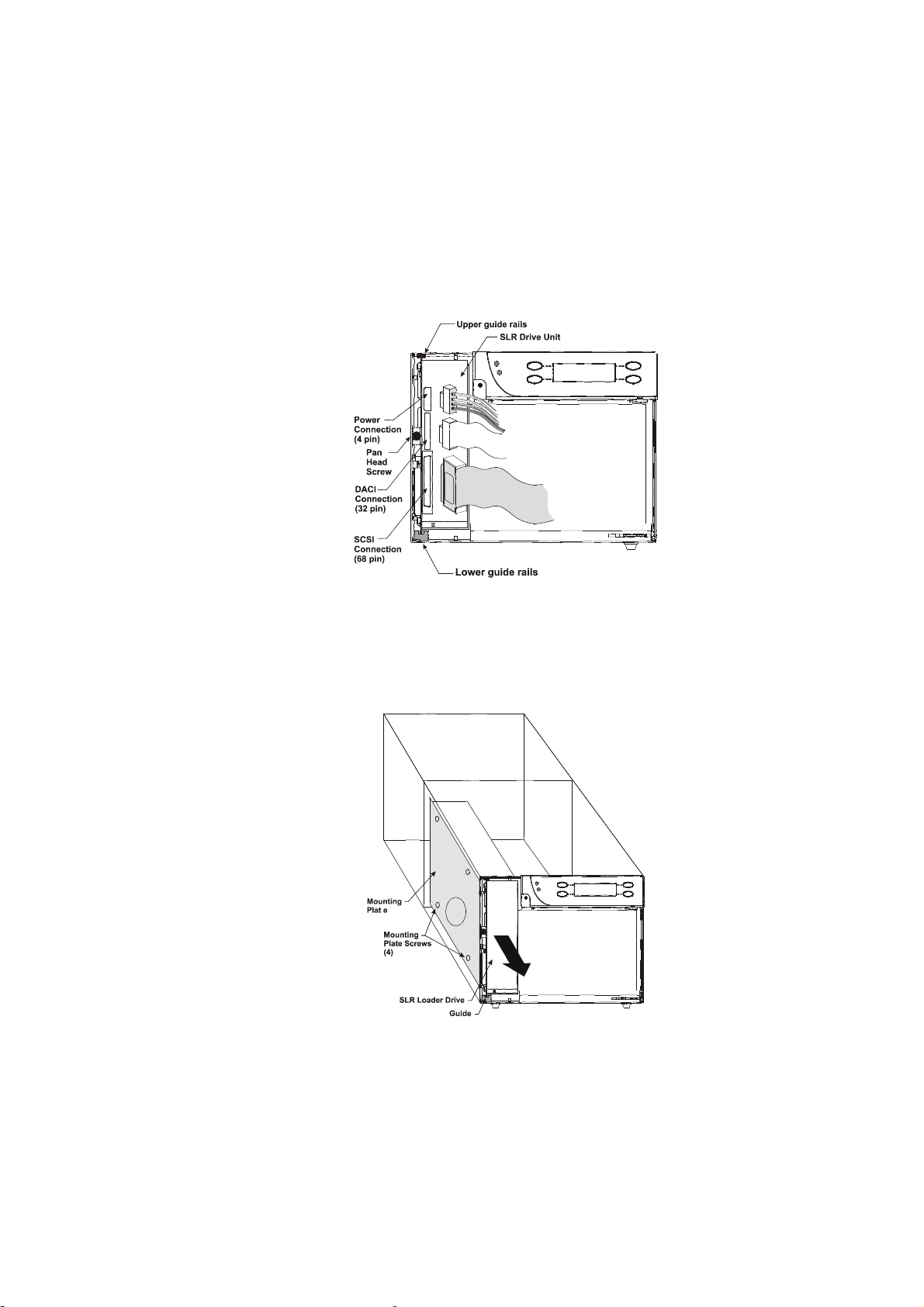
5. Remove the four M3 button socket head screws from the underside of the
painted cover.
6. Turn the unit back upright so that it is resting on its feet.
7. Slide the painted cover off toward the back of the unit.
8. Remove the four flat-head screws that hold the door panel assembly to the
chassis.
9. Disconnect the power, serial (DACI), and SCSI cables from the drive.
10. Remove the M3 x 6mm pan head screw and retainer that hold the drive to the
chassis.
11. Carefully folding the three cables clear, slide the drive out along the guide
channels molded into the chassis.
12. Remove the four M3 x 6mm pan head screws that holds the drive to the
mounting plate.
Tandberg SLR Autoloader Servive and Repair Manual 67

Tandberg Data Chapter 7 – Parts Removal and Replacement
To replace the drive
1. Turn off the power.
2. Insert the four M3 x 6mm pan head screws to fasten the drive to the mounting
plate.
3. Following the guide channels molded into the chassis, slide the drive into
position, between the pairs of lances.
4. Attach the power, serial (DACI), and SCSI cables to their connectors on the
drive. Attach the serial connector to the topmost pins.
5. Insert the M3 x 6mm pan head screw and retainer that holds the drive to the
chassis.
68 Tandberg SLR Autoloader Service and Repair Manual

6. Insert the four flat-head screws that hold the door panel assembly to the chassis.
7. Slide the painted cover on from the back of the unit.
8. Facing the door panel, gently place the unit on its left side.
9. Insert the four M3 button socket head screws into the underside of the painted
cover.
10. Turn the unit back upright so that it is resting on its feet.
11. Insert a magazine full of cartridges into the unit, and close the door.
12. Turn on the power and test the operation of the drive.
Tandberg SLR Autoloader Servive and Repair Manual 69

Tandberg Data Chapter 7 – Parts Removal and Replacement
The Robot Shuttle Assembly
Cleaning the Bar Code Reader
1. Press the Open Door button.
The robot shuttle moves over to operate the door latch, and the door swings
open.
Note: If the door does not open, refer to Appendix C – Emergency Magazine
Removal.
2. Turn off the power.
3. Pull out the magazine, and make sure that no cartridges are left in the robot
shuttle.
4. Facing the door panel, gently place the unit on its left side.
5. Remove four M3 button socket head screws from the underside of the painted
cover.
70 Tandberg SLR Autoloader Service and Repair Manual

6. Turn the unit back upright so that it is resting on its feet.
7. Slide the painted cover off toward the back of the unit.
8. Facing the front, gently place the unit on its left side.
9. Remove the 10 M3 x 6mm flat-head Phillips screws that fasten the right side
panel of the unit, and remove the panel. Turn the unit over on its feet.
10. Using a lens duster purchased from a camera shop carefully brush then blow
accumulated debris off of the Bar Code reader located in the shuttle assembly.
Do not use any form of solvent on the Bar Code reader or shuttle assembly.
Tandberg SLR Autoloader Servive and Repair Manual 71
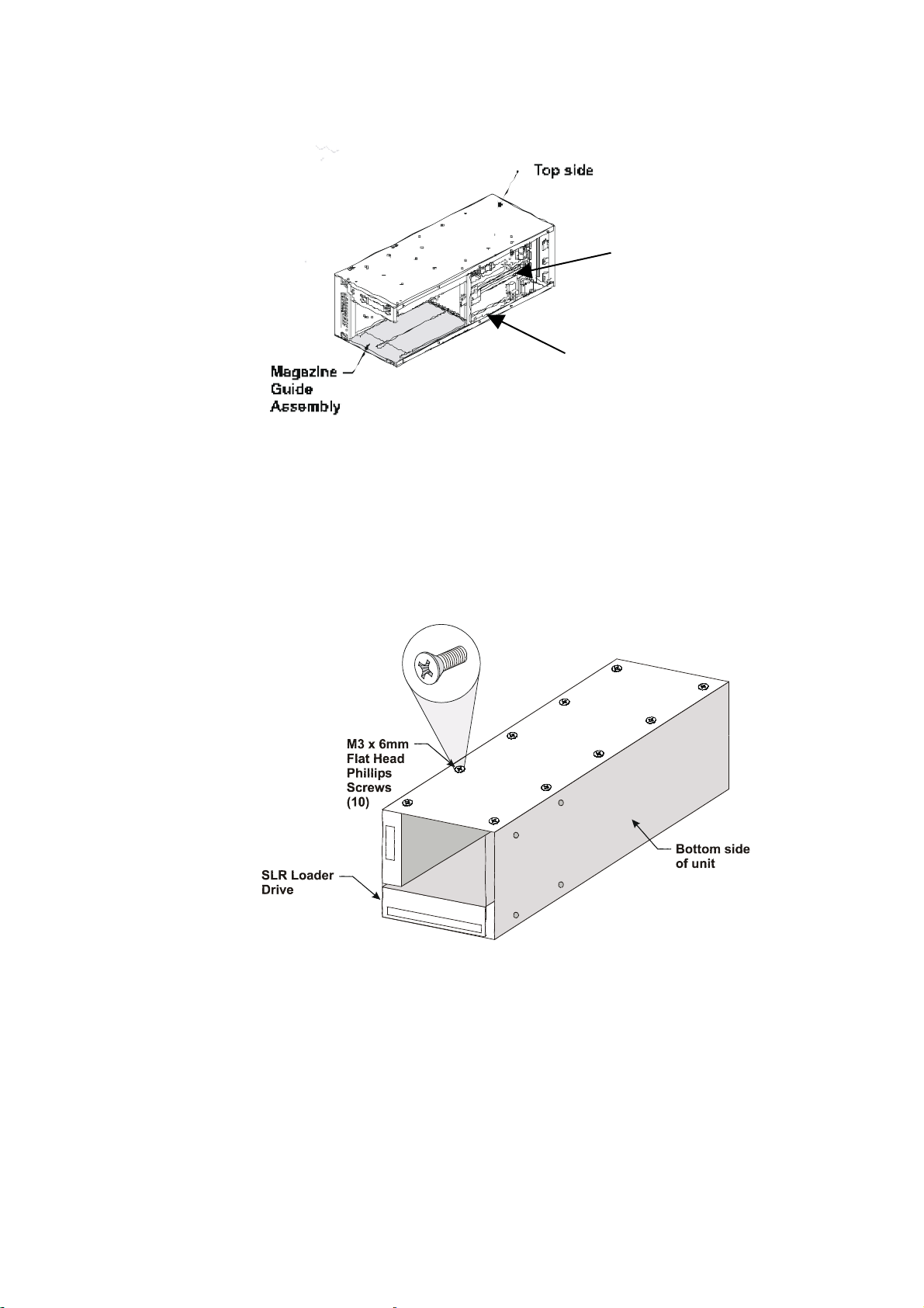
Tandberg Data Chapter 7 – Parts Removal and Replacement
Shuttle
Bar Code Reader
Re-assembly after bar code reader cleaning
1. Replace the right side panel and fasten with 10 M3 x 6mm flat-head Phillips
screws.
2. Turn the unit upright so that it is resting on its feet.
3. Starting from the back, slide the painted cover over the unit.
4. Turn the unit over on its left side.
72 Tandberg SLR Autoloader Service and Repair Manual

5. Insert the four M3 button socket head screws to fasten the underside of the
painted cover.
6. Turn the unit upright again so that it is resting on its feet.
7. Apply power to the unit, and unlock the door.
8. Insert a magazine, close the door, and test the operation of the unit.
To remove the robot shuttle assembly
1. Press the Open Door button.
The robot shuttle moves over to operate the door latch, and the door swings
open.
Note: If the door does not open, refer to Appendix C – Emergency Magazine
Removal.
2. Turn off the power.
3. Pull out the magazine, and make sure that no cartridges are left in the robot
shuttle.
4. Facing the door panel, gently place the unit on its left side.
5. Remove four M3 button socket head screws from the underside of the painted
cover.
Tandberg SLR Autoloader Servive and Repair Manual 73

Tandberg Data Chapter 7 – Parts Removal and Replacement
6. Turn the unit back upright so that it is resting on its feet.
7. Slide the painted cover off toward the back of the unit.
8. Facing the front, gently place the unit on its left side.
9. Remove the 10 M3 x 6mm flat-head Phillips screws that fasten the right side
panel of the unit, and remove the panel.
10. Remove the four M3 x 6mm flathead Phillips screws that fasten the lower
magazine guide assembly, and remove the assembly.
74 Tandberg SLR Autoloader Service and Repair Manual

11. Remove the cable retainer and unplug the ribbon cable from the main Printed
Wiring Board (PWB).
12. Reach in through the front of the chassis past the forward bulkhead, and place
your hand under the shuttle assembly.
13. Applying a slow uniform pressure, gently lift the shuttle assembly upward.
As the assembly rises, the pinion gears turn in their vertical racks and the
shuttle gear train is gently back driven.
14. When all the pinion gears have cleared the top of their racks, tilt the far side of
shuttle assembly slightly upward and lift it out of the unit, carefully avoiding
contact with the chassis.
Tandberg SLR Autoloader Servive and Repair Manual 75
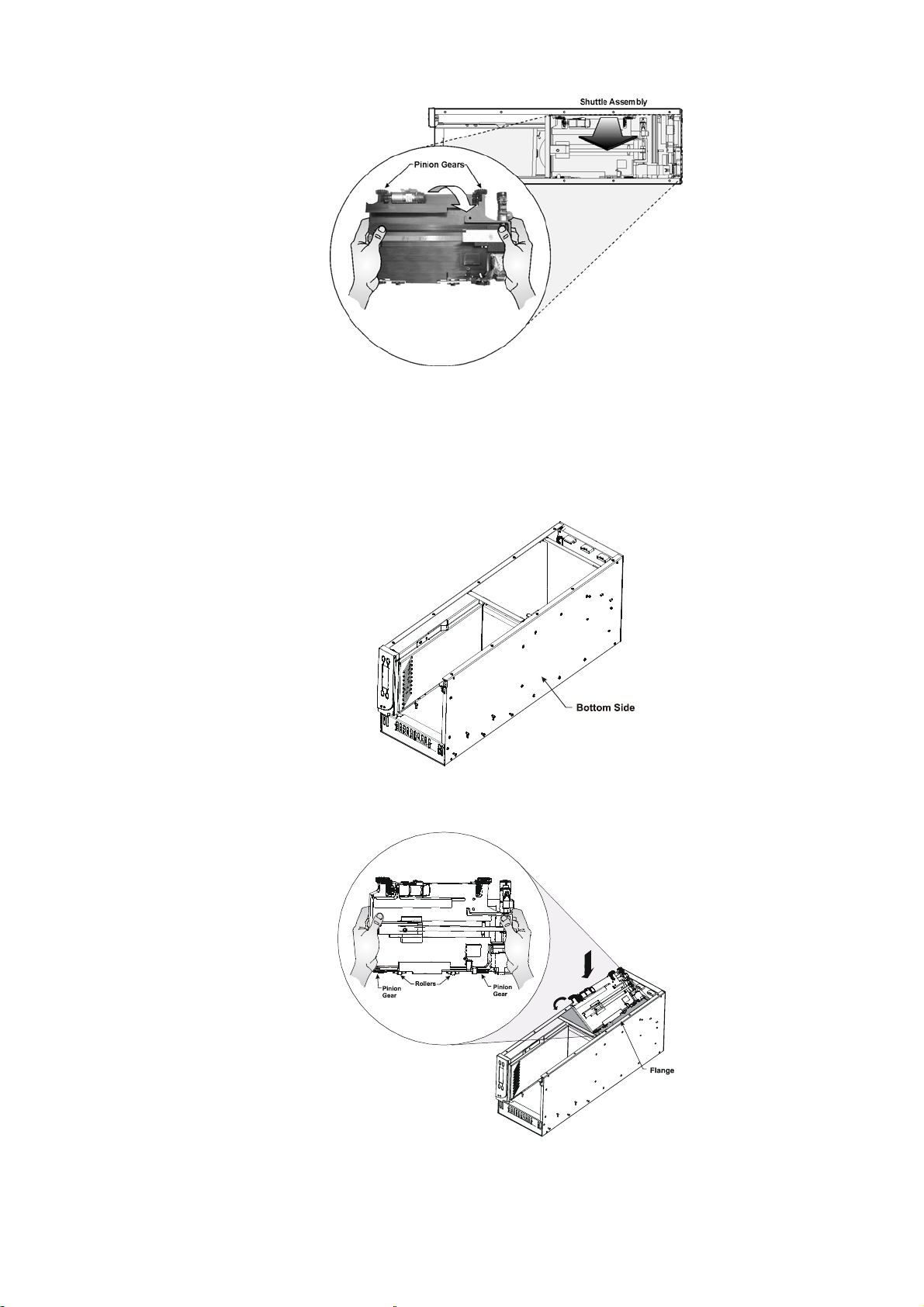
Tandberg Data Chapter 7 – Parts Removal and Replacement
To replace the robot shuttle assembly
1. Make sure electrical power to the unit is off.
2. Place the unit on its left side, with the bottom toward you, and the painted cover
and right side panel removed.
3. Holding the shuttle assemble with both hands, tilt the assembly so that the two
rollers contact the chassis bottom under the chassis flange.
4. Carefully engage the two closest pinion gears with their racks on the bottom
chassis panel.
76 Tandberg SLR Autoloader Service and Repair Manual

5. Tilt the shuttle assembly down to engage the other pair of pinion gears with their
racks.
6. Reach in through the front of the chassis past the forward bulkhead, and place
your hand under the shuttle assembly to assist in lowering it.
Note: For proper operation, the assembly should move through the racks in a
constantly level posture.
7. Applying a slow uniform pressure, gently push the shuttle assembly downward
for about ½ inch (1.27 cm).
As the assembly lowers, the pinion gears turn in their vertical racks and the
shuttle gear train is gently driven.
8. Check the uniform position of the four pinion gears relative to the top of their
racks. (If it’s not level front to rear, back the assembly out and start again.)
9. Check horizontal alignment of the shuttle assembly flange relative to the upper
part of the bulkhead. (If it’s not level, back the assembly out and start again.)
Tandberg SLR Autoloader Servive and Repair Manual 77

Tandberg Data Chapter 7 – Parts Removal and Replacement
10. Continue gently pushing until the assembly is at the bottom of its travel.
11. Insert the four M3 x 6mm flathead Phillips screws that fasten the lower
magazine guide assembly.
12. Attach the ribbon cable to the main PWB and replace the retainer.
13. Replace the right side panel and fasten with 10 M3 x 6mm flat-head Phillips
screws.
78 Tandberg SLR Autoloader Service and Repair Manual

14. Turn the unit upright so that it is resting on its feet.
15. Starting from the back, slide the painted cover over the unit.
16. Turn the unit over on its left side.
17. Insert the four M3 button socket head screws to fasten the underside of the
painted cover.
18. Turn the unit upright again so that it is resting on its feet.
19. Apply power to the unit, and unlock the door.
20. Insert a magazine, close the door, and test the operation of the unit.
Tandberg SLR Autoloader Servive and Repair Manual 79

Tandberg Data Chapter 7 – Parts Removal and Replacement
This Page Intentionally Left Blank
80 Tandberg SLR Autoloader Service and Repair Manual

Appendix A – Specifications
Operational Performance Specifications
Host Interfaces: Fast/Wide SCSI, Single-ended
Ultra-2, Low Voltage Differential
Number of Cartridges, Full Magazine 8
Media Compatibility:
Read Operations
SLR140 SLR7, SLR50, SLR60, SLR75, SLR140 Cartridges
SLR100 SLR7, SLR24, SLR40, SLR50, SLR60, SLR75 SLR100 Cartridges
SLR75 SLR7, SLR50, SLR60, SLR75 Cartridges
SLR60 SLR5, SLR7, SLR24, SLR40, SLR50, SLR60 Cartridges
Write Operations
SLR140 SLR140 Cartridges
SLR100 SLR40, SLR50, SLR60, SLR100 Cartridges
SLR75 SLR40, SLR50, SLR60, SLR75 Cartridges
SLR60 SLR40, SLR50, SLR60 Cartridges
Number of Drives 1
Load Time 10 sec. (max.), including picking from slot
Unload Time 10 sec. (max.), including returning to slot
Load to Ready Time 30 sec. (max.)
Sustained native data transfer rate, maximum
SLR140 6.0 MB/sec – 21,6 GB/hr*
SLR100 5.0 MB/sec - 18 GB/hr*
SLR75 4.0 MB/sec – 14,4 GB/hr*
SLR60 4.0 MB/sec – 14,4 GB/hr*
*GB/hour rates are nominal and may vary due to site-specific factors
Native Data Capacity (Full Magazine)
SLR140 560 GB
SLR100 400 GB
SLR75 300 GB
SLR60 240 GB
Reliability Specifications
MTBF robotics electronics ≥ 250,000 hours
MTBF power supply ≥ 100,000 hours
MTBF tape drive 300,000 hours
MTTR 30 min
Warranty 3 years factory
Robotics Mean-Exchanges-Between-Failures (MEBF) 250,000 cycles
Power Specifications
Voltage 110-240 VAC
Amperage 0.5-0.3 A
Line Frequency 50-60 Hertz
Tandberg SLR Autoloader Servive and Repair Manual 81

Tandberg Data Appendix A - Specifications
Notice
This product complies with the requirements for an IT Power System.
Mechanical Specifications
Height 6.84 in (17.4 cm)
Width 8.80 in (22.4 cm)
Depth 22.75 in (57.8 cm)
Weight 30 lbs (13.6 kg)
Shipping Weight 32 lbs (14.6 kg)
Shipping Size
Height 12.4 in (31.5 cm)
Width 13.8 in (35.1 cm)
Depth 29.2 in (74.2 cm)
Environmental Specifications
Operating
Ambient Temperature +41°F to +104°F (+5°C to +40°C)
Temperature Gradient 2°F/min,18° hour (1°C/min,10°C/hour)
Wet Bulb Temperature 79°F (26°C)
Relative Humidity (non-condensing) 20% to 80%
Altitude -1000 to +10,000 ft (-304.8 m to +3048 m)
Non-Operating (Packed or Unpacked)
Ambient Temperature. -4°F to +140°F (-20°C to +60°C)
Temperature Gradient 2°F/min,36° hour (1°C/min,20°C/hour)
Wet Bulb Temp. 84°F (29°C)
Relative Humidity (non-condensing) 10% to 90%
Altitude -1000 to +40,000 ft. (-304.8 to +12,192 m)
Acoustic Emissions
Tape drive operating <54 dBA
Tape drive plus robotic handler operating <54 dBA
Safety
All models of the SLR Autoloader carry the following Regulatory Agency product safety
certifications:
Certification Standard
UL Listed UL 1950
TUV/Product Service EN 60 950
GS Mark
CE Mark EMC Directive 89/336/EEC
Low Voltage Directive 72/23/EEC
Canadian UL Listed CSA 22.2 No. 950
82 Tandberg SLR Autoloader Service and Repair Manual
Electromagnetic Emission
Notice
This equipment has been tested using double shielded cables and terminators for EMI
compliance. The use of unshielded cables, terminators, or modifications requires
system testing for EMI testing for compliance to the standard.
Industry of Canada
This Class B digital apparatus meets all requirements of the Canadian Interferencecausing Equipment Standard ICES-003 Class B.
Industrie Canada
Cet appareil numérique de la classe B respecte toutes les exigencies du Standard ICES003 classe B sur le matériel brouilleur du Canada.
FCC Notice
This equipment has been tested and found to comply with the limits for a Class B digital
device, pursuant to Part 15 of the FCC rules. These limits are designed to provide
reasonable protection against harmful interference in a residential installation. This
equipment generates, uses and can radiate radio frequency energy and, if not installed and
used in accordance with the instructions, may cause harmful interference to radio
communications. However, there is no guarantee that interference will not occur in a
particular installation. If this equipment does cause harmful interference to radio or
television reception, which can be determined by turning the equipment off and on, the
user is encouraged to try to correct the interference by one or more of the following
measures:
— Reorient or relocate the receiving antenna
— Increase the separation between the equipment and receiver
— Connect the equipment into an outlet on a circuit different from that to which
the receiver is connected
— Consult the dealer or an experienced radio/TV technician for help.
Japanese Voluntary Control Council for Interference (VCCI)
Translation
This is a Class B product based on the standard of the Voluntary Control Council for
Interference from Information Technology Equipment (VCCI). If this is used near a radio
or television receiver in a domestic environment, it may cause radio interference. Install
and use the equipment according to the instruction manual.
Tandberg SLR Autoloader Servive and Repair Manual 83

Tandberg Data Appendix A - Specifications
This Page Intentionally Left Blank
84 Tandberg SLR Autoloader Service and Repair Manual

Appendix B – Spares/Accessories
Type Description P/N
Spares Complete Unit
PS/2 Grey
Black
Add-on/Replacement Drive
SLR140
SLR100
SLR75
SLR60
Loader Assembly
PS/2 Grey
Black
Accessories Data Cartridge 431891
Cleaning Cartridge 005678-2
Bar Code Labels (5 sets, 10 pieces each) 432075
Magazine 432076
Rackmount Kit (for 1 or 2 units) 006296
Locking Pin 968707-101
Screw for locking pin 970945-308
006294
006295
006784
006137
006840
006560
006449
006450
Tandberg SLR Autoloader Service and Repair Manual 85

Tandberg Data Appendix B – Spares/Accessories
This Page Intentionally Left Blank
86 Tandberg SLR Autoloader Installation and User Manual

Appendix C – Emergency Magazine
Removal
If a fault occurs that prevents the normal removal of the magazine, you can still
remove it using the emergency procedure described below:
1. Turn the power off.
2. Facing the front panel, gently turn the SLR Autoloader on its right side so you
can access its underside and the front panel overhangs the tabletop enough to
open freely.
3. Locate the oval-shaped slot in the bottom of the chassis.
4. Insert a straightened paperclip or similar narrow tool approximately ¼ inch into
the opening at the bottom of the slot.
5. Push the tool upward toward the hinged side of the front panel.
The tool moves the latch plate that opens the door.
6. Gently return the unit to its normal resting position, and swing the door open.
7. Grasp the handle, and slide the magazine out of the unit.
Tandberg SLR Autoloader Service and Repair Manual 87

Tandberg Data Appendix C – Emergency Magazine Removal
This Page Intentionally Left Blank
88 Tandberg SLR Autoloader Installation and User Manual
 Loading...