System Sensor PA400 User Manual

INSTALLATION AND MAINTENANCE INSTRUCTIONS
PA400* Series
Electronic Mini-Sounders
*ULC models add suffix “A”; available as regulated 24VDC only. Add suffix “R” for red models; “W” for white models; “B” for Beige model. PA400, add suffix “F” to models with fire printed on front.
3825 Ohio Avenue, St. Charles, Illinois 60174 1-800-SENSOR2, FAX: 630-377-6495 www.systemsensor.com
The products to which this manual applies may be covered by one or more of the following U.S. Patent numbers: 5,546,293 and 5,488,462
Specifications |
|
PA400 Sounder |
|
Voltages: |
Regulated 12DC and 24DC |
Operating Voltage Limits: |
8–17.5 and 16–33 |
Maximum Operating Current: |
At 12V– 20.8mA; at 24V– 47.4mA |
Temperature Range: |
–10°C to +60°C (14°F to 140°F) |
|
0°C to 49°C (32°F to 120°F) with strobe added |
Sound Output: |
74dBA minimum @ 10 feet – 12 volt application |
|
80dBA minimum @ 10 feet – 24 volt application |
NOTE: All PA400 series models were only tested at the 8–17.5 and 16–33 Volt DC limits. This does not include the 80% low-end or 110% high-end voltage limits.
General Information
The National Fire Protection Association has published codes, standards, and recommended practices for the installation and use of the above appliances. Therefore, the installer must be familiar with these requirements, with local codes, and any special requirements of the authority having jurisdiction.
Model PA400
The PA400W (white), PA400R (red), and PA400B (beige) Piezo Alert electronic sounder is intended to be connected to the alarm indicating circuit of a UL-listed 12 or 24 VDC fire alarm control panel.
Installation Notes
The wiring must be in compliance with all codes and must not be of such length or wire size that would cause the appliance to operate outside of its published specifications. The appliances must also be tested after installation in accordance with the control panel manufacturer’s test procedure.
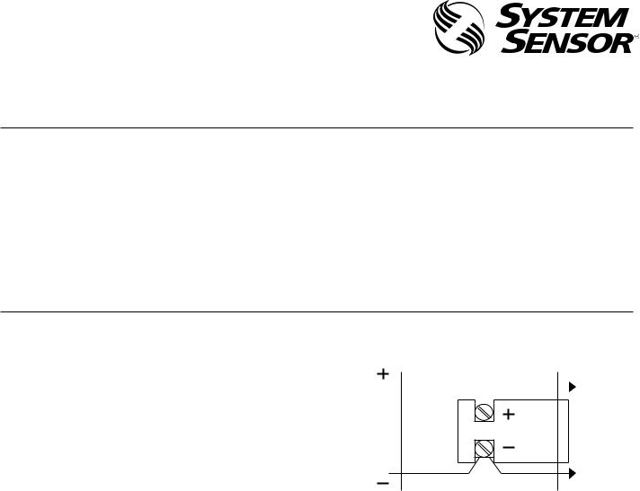
Figure 1:


|
|
|
|
|
|
|
|
|
A0204-00
*NOTE: Shown with control panel in alarm. Panel polarity reversed in supervisory condition.
NOTE: Do not loop wires under terminal screws. Wires connecting the device to the panel must be broken at the device screw terminal in order to maintain electrical supervision.
Mounting
PA400 Sounders
1.The PA400 is intended for mounting to a standard 21⁄2″ deep single-gang box which allows sufficient clearance for conduit entrance.
2.The PA400 is compatible with DC line supervision. The Piezo Alert is polarized and has terminals marked with polarity. Apply positive supply voltage to the (+) terminal and negative supply voltage to the (–) terminal. (See Figure 1.)
3.Mount the appliance to the electrical outlet box using the two mounting screws supplied.
4.Field repair of the PA400 should not be attempted. Return to factory for repair or replacement.
D200-13-00 |
1 |
I56-0305-011R |
 Loading...