


INSTALLATION AND MAINTENANCE INSTRUCTIONS
2112/24AT
Photoelectronic Smoke Detector with
Fixed Heat and Integral Temp-3 Sounder |
3825 Ohio Avenue, St. Charles, Illinois 60174 |
1-800-SENSOR2, FAX: 630-377-6495 |
Figure 1. Wiring diagram for the 2112/24AT detector:
IMPORTANT: OBSERVE POLARITY
As with all sounder models, polarity must be observed on the power connections.
POWER + TO
DETECTORS
–
|
|
|
|
|
|
|
|
|
|
EOL POWER |
|
|
|
|
|
|
|
|
|
|
SUPERVISION |
|
|
|
|
|
|
|
|
|
|
RELAY (SHOWN |
|
+ |
P |
+ |
P |
ENERGIZED) |
|||||
|
|
+ W |
+ W |
A77-716 12/24V |
||||||
|
|
– |
R |
– |
R |
|
||||
UL LISTED |
|
A |
ALARM |
A |
ALARM |
|
||||
|
A |
CONTACT |
A |
CONTACT |
|
|||||
COMPATIBLE |
|
EOL RESISTOR |
||||||||
CONTROL |
|
|
|
|
|
|
|
|
|
|
PANEL |
|
|
|
|
NOT USED |
|
|
|
NOT USED |
SPECIFIED BY |
|
|
|
|
|
|
|
PANEL |
|||
|
|
|
|
|
|
|
|
|
|
MANUFACTURER |
INITIATING |
|
|
|
|
|
|
|
|
|
|
LOOP |
|
|
|
|
|
|
|
|
|
|
|
|
|
|
|
OPTIONAL CLASS A WIRING |
|
|
|
|
A78-2336-14 |
|
|
|
|
|
|
|
|
|
|
|
|
|
|
|
|
|
|
|
|
|
|
Specifications |
|
|
|
|
|
|
|
|
|
|
Diameter: |
5.5 inches (140 mm) |
|
|
|
|
|
||||
Height (including mounting bracket): |
2.05 inches (52 mm) |
|
|
|
|
|
||||
Weight: |
7.5 oz. (210 g) |
|
|
|
|
|
||||
Operating Temperature Range: |
32° to 100° F (0° to 38° C) |
|
|
|
|
|
||||
Operating Humidity Range: |
10% to 93% Relative Humidity, Noncondensing |
|
||||||||
Latching Alarm: |
Reset by momentary power interruption |
|
||||||||
Audible Signal: |
85 dBA minimum when in alarm or with supply polarity reversed |
|||||||||
Heat Sensor: |
135°F Fixed Temperature Electronic Thermistor |
|
||||||||
Electrical Ratings |
|
|
|
|
|
|
|
|
|
|
System Voltage (nominal): |
12 or 24 VDC |
|
|
|
|
|
||||
Minimum: |
10 VDC |
|
|
|
|
|
|
|
||
Maximum: |
35 VDC |
|
|
|
|
|
|
|
||
Maximum Ripple Voltage: |
30% of nom. Voltage (peak to peak) |
|
||||||||
Standby Current: |
50 A maximum |
|
|
|
|
|
||||
Alarm Current: |
49 mA typical, 60 mA max. at 12V |
|
||||||||
|
57 mA typical, 65 mA max. at 24V |
|
||||||||
Reset Voltage: |
0.8 VDC minimum |
|
|
|
|
|
||||
Reset Time: |
1.0 second maximum |
|
|
|
|
|
||||
Start-up Time: |
30 seconds maximum (after 60 sec. reset) |
|
||||||||
EOL Relay: |
A77-716B, 12/24 VDC |
|
|
|
|
|
||||
Alarm Initiation |
|
|
|
|
|
|
|
|
|
|
Contact Rating, Resistive Load: |
1A @ 30 VDC |
|
|
|
|
|
||||
Special Considerations: |
Due to the built-in temporal pattern, use this detector only with a non-coded |
|||||||||
|
power supply. |
|
|
|
|
|
||||
Before Installing
Please thoroughly read the System Sensor manual I56-407,
Guide for Proper Use of System Smoke Detectors, which provides detailed information on detector spacing, placement, zoning, wiring, and special applications. Copies of this manual are available at no charge from System Sensor.
NOTICE: This manual shall be left with the owner/user of this equipment.
IMPORTANT: This detector must be tested and maintained following NFPA 72 requirements. The detector should be cleaned at least once a year.
D200-82-00 |
1 |
I56-1237-01R |
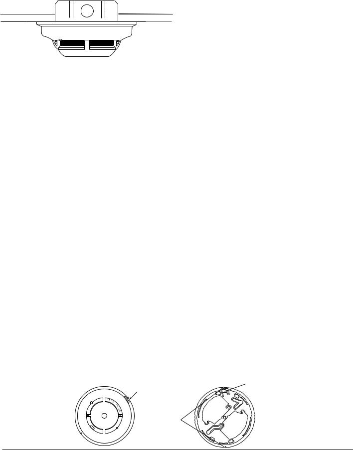
Figure 2. Surface mounting of 2112/24AT smoke detector on 31/2-inch and 4-inch octagonal box:
A78-2563-05
General Description
Model 2112/24AT is a 4-wire photoelectronic smoke detector that uses a state-of-the-art optical sensing chamber. The detector also provides restorable, 135˚F fixed-tempera- ture heat detection. The unit has a heat detection unit that is integrated with the photoelectronic sensor.
In addition, a piezoelectric horn in each detector produces an interrupted, 85 dBA tone when the individual detector alarms or when the supply voltage polarity is reversed.
NOTE: In order for all detectors on a loop to sound when the panel alarms, the panel must reverse the supply voltage polarity to that loop upon alarm. For panels that do not reverse the polarity during alarm, a reversing relay, such as System Sensor’s RR-2, must be used. The RR-2 is designed to allow all the detectors in the same loop to sound when one of the detectors goes into alarm. Some panels may require the use of programmable outputs. Refer to System Sensor literature for further information on the RR-2.
Installation of these detectors is simplified by the use of a mounting bracket and a plug-in screw terminal block that can be prewired to the system, allowing the detector to be easily installed or removed for cleaning. The detector’s sensitivity can be tested in place using the MOD400R Test Module.
An LED on the detector provides a local visual indication of the detector’s status. If power is applied to the detector and it is functioning normally in standby within the listed sensitivity range, the status LED blinks every ten seconds. The LED also latches on in alarm.
Figure 3. 2112/24AT smoke detector mounting bracket:
If the LED stops blinking, the unit should be removed for maintenance and inspection.
Mounting
Each 2112/24AT detector is supplied with a mounting bracket that permits the detector to be mounted:
1.To a single gang box, or
2.Directly to a 3-1/2 inch or 4 inch octagonal box, or
3.To a 4 inch square electrical box by using a plaster ring.
4.Directly to the ceiling using drywall anchors, if permitted by local codes and/or the authority having jurisdiction.
Tamper-resistant Feature
This detector includes a tamper-resistant feature that prevents its removal from the bracket without the use of a tool. To make the detector tamper-resistant, remove the smaller tab by breaking it at the scribed line on the tamper resistant tab on the detector mounting bracket (see Figure 3), then install the detector. To remove the detector from the bracket once it has been made tamper resistant, use a small screwdriver to depress the tamper-resistant tab, located in the slot on the mounting bracket, and turn the detector counterclockwise.
Wiring Installation Guidelines
All wiring must be installed in compliance with the National Electrical Code, applicable local codes, and any special requirements of the local authority having jurisdiction. Proper wire gauges should be used. The conductors used to connect smoke detectors to control panels and accessory devices should be color-coded to reduce the likelihood of wiring errors. Improper connections can prevent a system from responding properly in the event of a fire.
The screw terminal block accepts 14 – 22 gauge wire. For best system performance, all wiring should be installed in separate grounded conduit. Do not mix fire system wiring in the same conduit as any other electrical wiring. Twisted pair may be used to provide additional protection against electrical interference.
Smoke detectors and alarm system control panels have specifications for allowable loop resistance. Consult the control panel specifications for the total loop resistance allowed for the control panel being used before wiring the detector loops.
TAMPER SLOT (DEPRESS TAB TO REMOVE DETECTOR)
ALIGNMENT
ARROWS
TAMPER RESISTANT TAB (CUT OFF SMALL TAB TO ACTIVATE TAMPER-RESIST FEATURE)
A78-2333-01
D200-82-00 |
2 |
I56-1237-01R |
 Loading...