


INSTALLATION AND MAINTENANCE INSTRUCTIONS
|
3825 Ohio Avenue, St. Charles, Illinois 60174 |
D4120W Duct Smoke Detector |
1-800-SENSOR2, FAX: 630-377-6495 |
www.systemsensor.com |
NOTE: The D4120W duct detector consists of a Power Board and Sensor component.
Specifications
Operating Temperature:
Storage Temperature:
Environmental Rating:
Humidity:
Air Velocity:
D4120W Footprint Dimensions:
D4120W Weight: |
|
|
|
|
|
|
|
|
|
|
|
|
|
||
Electrical |
|
|
|
|
|
|
|
|
|
|
|
|
|
||
Power supply voltage: |
|
|
20-29 VDC |
|
|
24 VAC 50-60-Hz |
120 VAC 50-60 Hz |
|
|||||||
Input capacitance: |
|
|
270 µF max. |
|
|
270 µF max. |
N/A |
|
|
||||||
Reset Voltage: |
|
|
3.0 VDC min. |
|
|
2.0 VAC min. |
10 VAC min. |
|
|
||||||
Reset Time (with RTS451/RTS151): |
.03 to 0.3 sec. |
|
|
.03 to 0.3 sec. |
.03 to 0.3 sec. |
|
|
||||||||
Reset Time (by power down): |
|
0.6 sec. max. |
|
|
0.6 sec. max. |
0.6 sec. max. |
|
|
|||||||
Power Up Time: |
|
|
35 sec. max. |
|
|
35 sec. max. |
35 sec. max. |
|
|
||||||
Alarm response time: |
|
|
15 sec. |
|
|
15 sec. |
|
15 sec. |
|
|
|||||
Sensitivity Test: |
|
|
See detector label |
|
|
See detector label |
See detector label |
|
|||||||
Current Requirements (Using No Accessories) |
|
|
|
|
|
|
|
|
|
|
|||||
Max. standby current |
|
|
21 mA @ 24 VDC |
|
|
65 mA RMS @ 24VAC 60Hz |
20 mA RMS @ 120 VAC 60 Hz |
|
|||||||
Max. alarm current |
|
|
65 mA @ 24 VDC |
|
|
135 mA RMS @ 24 VAC 60 Hz |
35 mA RMS @ 120 VAC 60 Hz |
|
|||||||
|
|
|
|
|
|
|
|
|
|
|
|
|
|
||
|
CONTACT RATINGS |
|
|
|
|
|
|
|
|
|
|
|
|
||
|
|
|
|
|
|
|
|
|
ACCESSORY CURRENT LOADS AT 24 VDC |
|
|
||||
|
Alarm initiation contacts (SPST) |
2.0A @ 30 VDC (resistive) |
|
|
|
|
|
DEVICE |
STANDBY |
TROUBLE |
ALARM |
||||
|
|
|
|
|
|
|
|
|
|
APA151/APA451 |
12.5mA |
n/a |
30mA Max. |
||
|
Alarm auxiliary contatcs (DPDT) |
10A @30 VDC (resistive) |
|
|
|
|
|
||||||||
|
|
|
|
|
|
MHR/MHW |
|
0mA |
n/a |
29mA Max. |
|||||
|
|
|
10A @250 VAC (resistive) |
|
|
|
|
|
|
||||||
|
|
|
|
|
|
|
|
RA400Z/RA100Z |
|
0mA |
n/a |
12mA Max. |
|||
|
|
|
1/2 HP @240 VAC |
|
|
|
|
|
|
||||||
|
|
|
|
|
|
|
|
RTS451/RTS151 |
|
0mA |
n/a |
12mA Max. |
|||
|
|
|
1/4 HP @120 VAC |
|
|
|
|
|
|
||||||
|
|
|
|
|
|
|
|
RTS451KEY/RTS151KEY |
12mA |
n/a |
12mA Max. |
||||
|
NOTE: Alarm auxiliary contacts shall not be connected to initiating circuits of |
|
|
|
|
|
|
|
|||||||
|
|
|
RTS2 |
3mA Max. |
16mA Max. |
30mA Max. |
|||||||||
|
control panels. Use the alarm initiation contact for this purpose. |
|
|
|
|
|
RTS2-AOS |
|
3mA |
16mA Max. |
55mA Max. |
||||
|
Supervisory Contacts (SPDT) |
2.0A @ 30 VDC (resistive) |
|
|
|
|
|
|
|
|
|||||
|
|
|
|
|
|
NOTE: Any combination of accessories may be used such that the given |
|||||||||
|
|
|
2.0A @ 125 VAC (resistive) |
|
|
|
|
|
accessory loads are: 110mA or less at the Aux output, and 50mA or less at the |
||||||
Table of Contents |
|
|
|
|
|
Page |
Alarm output. |
|
|
|
|
||||
|
|
|
|
|
NOTICE: This manual shall be left with the owner/user of this equipment. |
||||||||||
[1] Limitations of Duct Smoke Detectors |
|
|
|
1 |
|
||||||||||
. . . . |
. . |
. . . |
|
|
|
|
|
|
|||||||
[2] Exploded View of Duct Smoke Detector Components . . |
. . |
. |
. . |
2 |
|
IMPORTANT: This detector must be tested and maintained regularly following |
|||||||||
[3] General Description. . |
. . . . . . . . . . . . . |
. . . |
. |
. 2 |
|
NFPA 72 requirements. The detector should be cleaned at least once a year. |
|||||||||
[4] Contents of Duct Smoke Detector Kit. . . . . . . . . . . . . . . . |
. . . . |
. . |
. . . |
. 2 |
|
[1] Limitations Of Duct Smoke Detectors |
|
||||||||
[5] Detector Installation |
|
|
|
|
|
|
2 |
|
|
||||||
. . . . . |
. . . . |
. . . . . . . . . . . . . . . . . |
. . . . |
. . |
. . . |
|
|
|
|
|
|
||||
|
|
|
|
|
|
|
|
|
|
|
|
||||
[6] Sampling Tube Installation |
. . . . . . . . . . |
. . |
. |
. . |
3 |
|
|
|
|
|
|
||||
|
|
|
WARNING |
|
|
||||||||||
. . .[7] Measurement Tests |
. . . . . . |
. . . |
. . . . . . . . . . . . . . . . . |
. . . . |
. . |
. . . |
. 3 |
|
The National Fire Protection Association has established that DUCT DETEC- |
||||||
[8] Field Wiring Installation Guidelines |
. . . . . . . . . . . . . . . . . |
. . . . |
. . |
. . . |
. 4 |
|
TORS MUST NOT BE USED AS A SUBSTITUTE FOR OPEN AREA DETECTOR |
||||||||
[9] Unit Configuration |
. . . . . . . . . . . . . |
. . |
. |
. . |
5 |
|
|||||||||
|
PROTECTION as a means of providing life safety. Nor are they a substitute for |
||||||||||||||
. . .[10] Detector Status Indication |
. . . |
. . . . . . . . . . . . . . . . . . |
. . . . |
. . |
. . |
. 6 |
|
early warning in a building’s regular fire detection system. |
|
||||||
. . . . . . . . . . . .[11] Interconnection (Multiple Fan Shut Down) |
. . . . |
. . |
. . |
. 6 |
|
System Sensor supports this position and strongly recommends that the user |
|||||||||
[12] Verification of Operation |
|
|
|
|
|
6 |
|
||||||||
. . . |
. . . . . . . . . . . . . . . . . . |
. . . . |
. . |
. . |
|
read NFPA Standards 90A, 72, and 101. The D4120W Air Duct Smoke Detec- |
|||||||||
[13] Detector Cleaning Procedures |
. . . . . . . . . |
. . |
. |
. |
. 7 |
|
|||||||||
|
tors are listed per UL 268A. |
|
|
|
|
||||||||||
[14] Sensor replacement |
|
|
|
|
|
|
7 |
|
|
|
|
|
|||
. . . . . . |
. . . |
. . . . . . . . . . . . . . . . . . |
. . . . |
. . |
. . |
|
|
|
|
|
|
||||
[15] Optional Accessories. . |
. . . . . |
. . . |
. . . . . . . . . . . . . . . . . . |
. . . . |
. . |
. . |
. 7 |
|
This device will not operate without electrical power. Fire situations may |
||||||
Wiring Diagrams . . . . . . . . |
. . . . . |
. . . |
. . . . . . . . . . . . . . . . . . |
. . . . |
. . |
. . |
5-7 cause an interruption of power. The system safeguards should be discussed |
||||||||
Warranty . . . . . . . . . . . . . . |
. . . . . |
. . . |
. . . . . . . . . . . . . . . . . . |
. . . . |
. . |
. . |
8 with your local fire protection specialist. |
|
|
||||||
Before Installing |
|
|
|
|
|
|
|
|
This device will not sense smoke unless the ventilation system is operating |
||||||
To maintain the watertight properties of this duct smoke detector, watertight |
|||||||||||||||
and the cover is installed. |
|
|
|
|
|||||||||||
conduit and fittings must be used. Mount the product with the conduit holes |
|
|
|
|
|||||||||||
For this detector to function properly, it MUST be installed according to the in- |
|||||||||||||||
facing downwards, if possible. Read the System Sensor Guide for Proper Use of |
|||||||||||||||
structions in this manual. Furthermore, the detector MUST be operated within |
|||||||||||||||
Smoke Detectors in Duct Applications (A05-1004), which provides information |
|||||||||||||||
ALL electrical and environmental specifications listed in this manual. Failure |
|||||||||||||||
on detector spacing, placement, zoning, wiring, and special applications. This |
|||||||||||||||
to comply with these requirements may prevent the detector from activating |
|||||||||||||||
manual is available online at www.systemsensor.com. NFPA Standards 72 and |
|||||||||||||||
when smoke is present in the air duct. |
|
|
|||||||||||||
90A should also be referenced for detailed information. |
|
|
|
|
|
|
|
||||||||
|
|
|
|
|
|
|
|
|
|
||||||
|
|
|
|
|
|
|
|
|
|
|
|
|
|
|
|
SS-300-010 |
|
|
|
|
|
|
1 |
|
|
|
I56-3046-004R |
||||
004R-3046-I56

[2] Figure 1. Exploded View of Duct Smoke Detector Components:
EXHAUST TUBE
METAL
SAMPLING TUBE (sold seperately)
SENSOR HEAD
MAGNET TEST LOCATION
[3] General Description
Smoke introduced into an air duct system will be distributed throughout the entire building. Smoke detectors designed for use in air duct systems are used to sense the presence of smoke in the duct.
Model D4120W. Duct Smoke Detectors utilize 4-wire photoelectric technology for the detection of smoke. This detection method, when combined with an efficient housing, samples air passing through the duct allowing detection of a developing hazardous condition. When sufficient smoke is sensed, an alarm signal is initiated and appropriate action can be taken to shut off fans, blowers, change over air handling systems, etc. These actions can facilitate the management of toxic smoke and fire gases throughout the areas served by the duct system.
The D4120W detectors are designed to operate on 24 VDC/VAC or 120 VAC. Alarm and supervisory relay contacts are available for control panel interface (alarm initiation), HVAC control, and other auxiliary functions. Auxiliary relays are provided for fan shut down. Detector interconnection provides signaling of up to 50 other detectors in the loop for multiple fan shut down. These detectors are not designed for 2-wire applications.
[3.1] Detector Feature Set
-Utilizes 2D51 plug-in head
-2 sensors to 1 power board capability -Cover missing signal
-Sampling tubes install from front or rear of detector -Compatible with existing accessories
[4] Contents Of The Duct Smoke Detector Kit
1.Sensor/power board assembly and cover(s)
2.Three #10 sheet metal screws for mounting
3.Drilling template
4.One sampling tube end cap
5.One plastic exhaust tube
NOTE: A sampling tube must be ordered to complete the installation. It must be the correct length for the width of the duct where it will be installed. See Table 1 on page 3 to determine the inlet tube required for different duct widths.
[5] Detector Installation
[5.1] Verify Air Flow Direction And Velocity
Model D4120W detectors are designed to be used in air handling systems with air velocities of 100 to 4000 feet per minute. Duct widths from 6 inches to 12 feet can be accommodated. Be sure to check engineering specifications to ensure that the air velocity in the duct falls within these parameters. If necessary, use a velocity meter (anemometer) to check the air velocity in the duct.
4-WIRE
POWER BOARD
POWER BOARD MODULE COVER
SENSOR MODULE
COVER
H0549-06
[5.2] Determine Mounting location and Configuration
On ducts wider than 18 inches it is recommended that the detector be mounted downstream of a bend, obstruction in the duct, or the supply or return air inlet.
Exception: Installation of duct detectors can be on or within a commercial packaged rooftop heating and air-conditioning system, fire/smoke dampers and economizers. They may be mounted in either the supply and/or return air section as determined by local code.
Once a suitable location is selected, determine if the detector is to be mounted in a side-by-side “rectangular” configuration or a top-over-bottom “square” configuration as shown in Figure 2. If mounting in the square configuration, remove the rear attachment screw, rotate the unit at the hinge, and replace the screw into the new attachment hole as shown in Figure 2. Do NOT remove the hinge screw during this process. Final installation approval shall be based upon passing section 7.2.2 and/or 8.2.4 tests.
Figure 2: |
|
REMOVE SCREW AND PIVOT |
REPLACE SCREW |
DETECTOR AS SHOWN BELOW. |
TO SECURE DETECTOR |
|
IN PLACE. |
H0550-00
[5.3] Drill the Mounting Holes
Remove the paper backing from the mounting template supplied. Affix the template to the duct at the desired mounting location. Make sure the template lies flat and smooth on the duct.
[5.3.1] For rectangular side-by-side mounting configuration:
Center punch at (4) target centers: (2) “A” for sampling tubes and (2) “B” for the rectangular configuration mounting tabs as shown on mounting template. Drill pilot holes at target “A” centers and cut two 1.375 inch diameter holes using a 13/8 inch hole saw or punch. Drill .156 inch diameter holes using a 5/32 inch drill at target “B” centers.
SS-300-010 |
2 |
I56-3046-004R |
[5.3.2] For square top-over-bottom mounting configuration or D4S sensor component mounting:
Center punch at (4) target centers: (2) “A” for sampling tubes and (2) “C” for the square configuration mounting tabs as shown on mounting template. Drill pilot holes at target “A” centers and cut two 1.375 inch diameter holes using a 13/8 inch hole saw or punch. Drill .156 inch diameter holes using a 5/32 inch drill at target “C” centers. If desired, drill an additional .156 inch hole at the location of one of the mounting tabs on the lower housing.
[5.4] Secure the Duct Detector to the Duct
Use two (rectangular configuration) or three (square configuration) of the provided sheet metal screws to screw the duct detector to the duct.
CAUTION: Do not overtighten the screws.
[6] Sampling Tube Installation [6.1] Sampling Tube Selection
The sampling tube must be purchased separately. Order the correct length, as specified in Table 1, for width of the duct where it will be installed. It is recommended that the sampling tube length extend at least 2/3 across the duct width for optimal performance.
Table 1. Sampling tubes recommended for different duct widths:
Outside Duct Width |
Sampling Tube Recommended* |
Up to 1 ft. |
DST1 |
1 to 2 ft. |
DST1.5 |
2 to 4 ft. |
DST3 |
4 to 8 ft. |
DST5 |
8 to 12 ft. |
DST10 (2-piece) |
*Must extend a minimum of 2/3 the duct width. These sampling tubes can only be used with new InnovairFlex duct smoke detectors.
The sampling tube is always installed with the air inlet holes facing into the air flow. To assist proper installation, the tube’s connector is marked with an arrow. Make sure the sampling tube is mounted so that the arrow points into the airflow as shown in Figure 3. Mounting the detector housing in a vertical orientation is acceptable provided that the air flows directly into the sampling tube holes as indicated in Figure 3. The sampling tube and exhaust tube can be mounted in either housing connection as long as the exhaust tube is mounted downstream from the sampling tube.
Figure 3. Air duct detector sampling tube:
SAMPLING TUBE ENDCAP
ARROW MUST FACE |
AIR FLOW |
INTO AIR FLOW |
DIRECTION |
|
H0551-00 |
CAUTION: The sampling tube end cap, included with the detector, is critical to proper operation of the duct smoke detector. The end cap is needed to create the proper air flow to the sensor of the duct smoke detector. Once any sampling tube length adjustments are made, plug the end of the sampling tube with the provided end cap.
A plastic exhaust tube is included with the unit to be installed if needed. Install into the housing connection that is downstream from the sampling tube connection. The exhaust tube can be installed from the front or back of the detector. A longer 1 foot exhaust tube, model ETX, is available as an accessory in cases where the molded exhaust tube does not extend at least 2 inches into the duct.
[6.2] Sampling Tube Installation
1.For tubes shorter than the width of the duct, slide the sampling tube, with installed end cap, into the housing connection that meets the airflow first. Position the tube so the arrow points into the airflow as shown in Figure 3. Per NFPA sampling tubes over 3 feet long should be sup-
ported at the end opposite the duct detector. In ducts wider than 8 feet, work must be performed inside the duct to couple the other section of the sampling tube to the section already installed using the 1/2 inch conduit fitting. Make sure that the holes on both sections of the air inlet sampling tube are lined up and facing into the airflow.
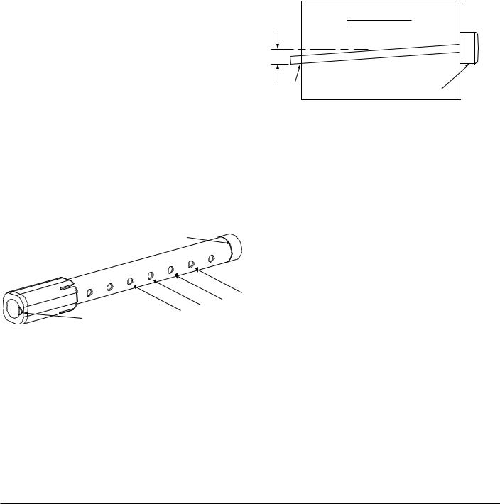
2.For tubes longer than the width of the duct, the tube should extend out of the opposite side of the duct. Drill a 3/4 inch hole in the duct opposite the hole already cut for the sampling tube. Ensure that the sampling tube is angled downward from the duct smoke detector to allow for moisture drainage away from the detector. The sampling tube should be angled at least 1/4” downward for every 12” of duct width per Figure 4. There should be 10 to 12 holes spaced as evenly as possible across the width of the duct. If there are more than 2 holes in the section of the tube extending out of the duct, select a shorter tube using Table 1. Otherwise, trim the tube to leave approximately 1 to 2 inches extending outside the duct. Plug the end with the end cap and tape closed any holes in the protruding section of tube. Be sure to seal the duct where the tube protrudes.
Figure 4.
12˝
1/4˝
2˝
3 |
4 |
˝ |
DETECTOR |
|
/ |
||
HOLE |
|
||
H0215-00
NOTE: Air currents inside the duct may cause excessive vibration, especially when the longer sampling tubes are used. In these cases, a 3 inch floor flange (available at most plumbing supply stores) may be used to fasten the sampling tube to the other side of the duct. When using the flange/connector mounting technique, drill a 1 to 11/4 inch hole where the flange will be used.
[6.3] Modifications of Sampling Tubes
There may be applications where duct widths are not what is specified for the installation. In such cases, it is permissible to modify a sampling tube that is longer than necessary to span the duct width.
Use a 0.193 inch diameter (#10) drill and add the appropriate number of holes so that the total number of holes exposed to the air flow in the duct is 10 to 12. Space the additional holes as evenly as possible over the length of the tube.
NOTE: This procedure should only be used as a temporary fix and is not intended as a substitute for ordering the correct length tubes.
[6.4] Remote Sampling Tube Installation
The detector arrangement can also incorporate remote mounting of the sampling tube and/or exhaust tube. In this case both the detector, sampling tube and exhaust tube (if included) should be rigidly mounted to withstand the pressure and vibrations caused by the air velocity. The location of the detector’s sampling tube should be such that there is uniform airflow in the cross section area.
The pressure differential across the sampling and exhaust ports in the detector housing shall be verified to be between 0.01 and 1.11 inches of water. Do so by measuring the pressure difference between the inlet and outlet ports on the detector housing using a manometer as described in Section 7.1.
[7] Measurement tests [7.1] air flow
The D4120W is designed to operate over an extended air speed range of 100 to 4000 FPM. To verify sufficient sampling of ducted air, turn the air handler on and use a manometer to measure the differential pressure between the two sampling tubes. The differential pressure should measure at least 0.01 inches of water and no more than 1.11 inches of water. Because most commercially available manometers cannot accurately measure very low pressure differentials, applications with less than 500 FPM of air speed may require one of the following: 1) the use of a current-sourcing pressure transmitter (Dwyer Series 607) per Section 7.2, or 2) the use of aerosol smoke per section 12.5.3.
SS-300-010 |
3 |
I56-3046-004R |
 Loading...