


2112-24B

D200-62-00 1 I56-932-01
2112/24B and 2112/24TB
Photoelectronic
Smoke Detectors
INSTALLATION AND MAINTENANCE INSTRUCTIONS
A Division of Pittway
3825 Ohio Avenue, St. Charles, Illinois 60174
1-800-SENSOR2, FAX: 630-377-6495
Before Installing
Please thoroughly read the System Sensor manual I56-407,
Guide for Proper Use of System Smoke Detectors, which
provides detailed information on detector spacing, place-
ment, zoning, wiring, and special applications. Copies of
this manual are available at no charge from System Sensor.
NOTICE: This manual should be left with the owner/user
of this equipment.
IMPORTANT: This detector must be tested and maintained
following NFPA 72 requirements. The detector should be
cleaned at least once a year.
General Description
Model 2112/24B is a 4-wire photoelectronic smoke detector
that uses a state-of-the-art optical sensing chamber. This
detector is designed to provide open area protection. Model
Specications
Diameter: 5.5 inches (140 mm)
Height (including mounting bracket): 1.7 inches (43 mm)
Weight: 5.3 oz. (150 g)
Operating Temperature Range
Model 2112/24B: 32° to 120°F (0° to 50°C)
Model 2112/24TB: 32° to 100°F (0° to 39°C)
Operating Humidity Range: 10% to 93% Relative Humidity, Noncondensing
Latching Alarm: Reset by momentary power interruption
Heat Sensor (2112/24TB only): 135°F Fixed Temperature Electronic Thermistor
Electrical Ratings
System Voltage (nominal): 12 or 24 VDC
Minimum: 8.5 VDC
Maximum: 35 VDC
Maximum Ripple Voltage: 30% of nom. Voltage (peak to peak)
Standby Current: 50 µA maximum
Alarm Current: 17 mA typical, 23 mA max. at 12V
19 mA typical, 25 mA max. at 24V
Reset Voltage: 0.8 VDC minimum
Reset Time: 0.3 seconds maximum
Start-up Time: 30 seconds maximum (after 60 sec. reset)
EOL Relay: A77-716B, 12/24 Volt
Alarm Initiation Contact Ratings
Resistive or inductive load (60% power factor)
Form A: 0.5A @ 30 VAC/DC
2112/24TB features a restoreable, built-in, xed-tempera-
ture (135°F) thermal detector.
Installation of these detectors is simplied by the use of a
mounting bracket and a plug-in screw terminal block that
can be prewired to the system, allowing the detector to be
easily installed or removed for cleaning. The detector’s
sensitivity can be tested in place using the MOD400R Test
Module.
An LED on the detector provides a local visual indication of
the detector’s status. If power is applied to the detector, and
it is functioning normally in standby, the status LED blinks
every ten seconds. The LED also latches on in alarm.
Models 2112/24B and 2112/24TB feature a visual indication
that maintenance is required – if the sensing chamber drifts
out of its sensitivity limits, the LED ceases to blink.
D200-62-00 2 I56-932-01
Mounting
Each 2112/24B and 2112/24TB detector is supplied with a
mounting bracket that permits the detector to be mounted:
1. To a single gang box, or
2. Directly to a 3-1/2 inch or 4 inch octagonal box, or
3. To a 4 inch square electrical box by using a plaster ring.
Tamper-resistant Feature
This detector includes a tamper-resistant feature that pre-
vents its removal from the bracket without the use of a
tool. To make the detector tamper-resistant, remove the
smaller tab by breaking it at the scribed line on the tamper
resistant tab on the detector mounting bracket (see Figure
2), then install the detector. To remove the detector from
the bracket once it has been made tamper resistant, use
a small screwdriver to depress the tamper-resistant tab,
located in the slot on the mounting bracket, and turn the
detector counterclockwise.
Wiring Installation Guidelines
All wiring must be installed in compliance with the Na-
tional Electrical Code, applicable local codes, and any spe-
cial requirements of the local authority having jurisdiction.
Proper wire gauges should be used. The conductors used
to connect smoke detectors to control panels and accessory
devices should be color-coded to reduce the likelihood of
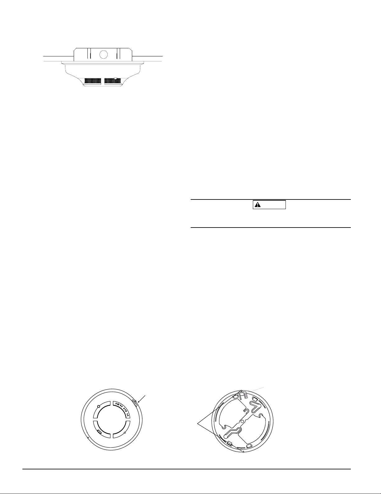
D
O
N
O
T
P
A
I
N
T
TAMPER SLOT
(DEPRESS TAB TO
REMOVE DETECTOR)
TAMPER RESISTANT TAB
(CUT OFF SMALL TAB TO
ACTIVATE TAMPER-RESIST
FEATURE)
ALIGNMENT
ARROWS
Figure 1. Surface mounting of 2112/24B smoke de-
tector on 3
1
/
2
inch and 4 inch octagonal box:
A78-2563-00
Figure 2. 2112/24B and 2112/24TB smoke detector mounting bracket:
A78-2333-01
wiring errors. Improper connections can prevent a system
from responding properly in the event of a re.
The screw terminal block accepts 14 – 22 gauge wire. For
best system performance, all wiring should be installed in
separate grounded conduit. Do not mix re system wiring
in the same conduit as any other electrical wiring. Twisted
pair may be used to provide additional protection against
electrical interference.
Smoke detectors and alarm system control panels have
specications for allowable loop resistance. Consult the
control panel specications for the total loop resistance
allowed for the control panel being used before wiring the
detector loops.
Wire connections are made by stripping about 1/4 inch of
insulation from the end of the feed wire, inserting the wire
into the appropriate terminal, and tightening the screw to
secure the wire in place.
Installation
WARNING
Remove power from the control unit or initiating device
circuits before installing detectors.
1. Wire the plug-in screw terminal block per Figure 3 and
plug the terminal block into the detector.
2. Align the arrows on the detector with the arrows on the
mounting bracket.
3. Turn the detector clockwise in the mounting bracket un-
til it clicks into place.
4. After all detectors have been installed, apply power to
the control unit or initiating device circuits.
5. Test the detector as described in TESTING.
6. Reset the detector at the system control panel.
7. Notify the proper authorities the system is in operation.
 Loading...