

Suzuki DL650 2003 Owner's manual
NSD Ref. P4023/9
OWNER'S MANUAL
SUZUKl
IMPORTANT
BREAK-IN (RUNNING-IN)
INFORMATION FOR YOUR
MOTORCYCLE
The first 1600 km (1 000 miles) are the
most important in the life of your
motorcycle. Proper break-in operation
during this time will help ensure maximum life and performance from your
new motorcycle. Suzuki parts are
manufactured of high quality materials, and machined parts are finished
to close tolerances. Proper break-in
operation allows the machined surfaces to polish each other and mate
smoothly.
Motorcycle reliability and performance depend on special care and
restraint exercised during the break-in
period. It is especially important that
you avoid operating the engine in a
manner which could expose the
engine parts to excessive heat.
Please refer to the BREAK-IN (RUNNING-IN) section for specific break-in
recommendations.
WARNINGICAUTIONINOTE
Please read this manual and follow its
instructions carefully. To emphasize
special information the words WARN-
ING, CAUTION and NOTE carry special meanings and should be carefully
reviewed.
The personal safety of the rider
may be involved. Disregarding
this information could result in
injury to the rider.
CAUTION
These instructions point out special service procedures or precautions that must be followed to
avoid damaging the machine.
NOTE: This Drovides s~ecial informa
tion to maki maintenance easier or
important instructions clearer.
FOREWORD
TABLE OF
CONTENTS
Motorcycling is one of the most exhilarating sports and to ensure your
riding enjoyment. you should become
thoroughly familiar with the information presented in this Owner's Manual
before riding the motorcycle
The proper care and maintenance
that your motorcycle requires is outlined in this manual
these instructions explicitly you will
ensure a long trouble free operating
life for your motorcycle
rized Suzuki dealer has experienced
technicians that are trained to provide
your machine with the best possible
service with the right tools and equipment
.
All information. illustrations. photographs and specifications contained
in this manual are based on the latest
product information available at the
time of publication
ments or other changes. there may
be some discrepancies in this man-
.
Suzuki reserves the right to make
ual
changes at any time
Please note that this manual applies
to all specifications or all respective
destinations and explains all equipment
.
Therefore. your model may
have different standard features than
shown in this manual
SUZUKl MOTOR CORPORATION
0
COPYRIGHT SUZUKl MOTOR
CORPORATION
.
.
2003
.
.
By following
.
Your autho-
Due to improve-
.
CONSUMER INFORMATION
ACCESSORY USE AND
MOTORCYCLE LOADING
SAFE RIDING RECOMMENDATION
FOR MOTORCYCLE RIDERS
SERIAL NUMBER LOCATION
LOCATION OF PARTS
CONTROLS
KEY
IGNITION SWITCH
INSTRUMENT PANEL
LEFT HANDLEBAR
RIGHT HANDLEBAR
FUEL TANK CAP
GEARSHIFT LEVER
REAR BRAKE PEDAL
SEAT LOCK
HELMET HOLDER
SIDE STAND
SUSPENSION ADJUSTMENT
WINDSHIELD HEIGHT
ADJUSTMENT
FUEL. ENGINE OIL AND
COOLANT RECOMMENDATION
FUEL
ENGINE OIL
COOLANT
BREAK-IN (RUNNING-IS
MAXIMUM ENGINE SPEED
RECOMMENDATION
VARY THE ENGINE SPEED
BREAKING IN THE
AVOID CONSTANT LOW SPEED 31
ALLOW THE
CIRCULATE BEFORE
OBSERVE YOUR
CRITICAL
INSPECTIOS
RIDING
STARTING
........................................
.......................................................
..................................
.............................
.................................
...............................
.....
::
............................
................................
............................
............................................
...................................
...........................................
.......................
........................................................
.............................................
................................................
..............................
NEW
EM
SERVICE
TIPS
M
011
Wl)(G
RRST
......................
BEFORE
......................................
W(ilE
............
........................
...................
..................
.......................
................
..
...........
...............
...................
TIRES
.............
...........
TO
...............
AND MOST
RIDING
,
.......
....................
...
I
11
11
13
18
19
21
22
22
23
23
24
25
27
28
28
29
29
30
30
30
30
31
31
31
33
33
4
4
6
7
8
I
2
STARTING OFF
USING THE TRANSMISSION
RIDING ON HILLS
STOPPING AND PARKING
INSPECTION AND
MAINTENANCE
MAINTENANCE SCHEDULE
TOOLS
FUEL TANK LIFT
LUBRICATION POINTS
BAllERY
AIR CLEANER
SPARK PLUGS
FUEL HOSE
ENGINE OIL
IDLE SPEED
THROllLE CABLE PLAY
COOLANT
DRIVE CHAIN
CLUTCH
BRAKES
TIRES
.......................................................
SIDE STANDnGNlTlON
INTERLOCK SWITCH
FRONT WHEEL REMOVAL
REAR WHEEL REMOVAL
LIGHT BULB REPLACEMENT
FUSES
TROUBLESHOOTING
MOTORCYCLE CLEANING
STORAGE PROCEDURE
SPECIFICATIONS .............................
.....................................
.................
...................................
.....................
................................
..................
.....................................................
....................................
..........................
................................................
.........................................
......................................
.............................................
.............................................
............................................
......................
................................................
..........................................
...................................................
..................................................
............................
....................
......................
...............
.....................................................
......................
............
..................
33
34
35
36
37
37
40
40
41
42
43
45
47
48
51
52
53
54
57
58
62
65
66
6E
6f
7i
7:
74
7C
7t
CONSUMER INFORMATION
ACCESSORYUSEAND
MOTORCYCLE LOADING
Accessory Use
The addition of unsuitable accesso
ries can lead to unsafe operating con
ditions. It is not possible for Suzuki
test each accessory on the market o
combinations of all the availablt
accessories; however, your deale
can assist you in selecting qualit!
accessories and installing them cor
rectly. Use extreme caution wher
selecting and installing the accesso
ries on your motorcycle and consul
your Suzuki dealer if you have an!
questions.
Improper accessory installation
can make your motorcycle unsafe
and can lead to an accident.
Use Suzuki genuine accessories
or equivalent, designed and tested
for your motorcycle. Follow the
guidelines in this section.
tc
Accessory installation
Install - aerodynamic afled~ng
accessories, such
windshield, backrests, saddlebags, and travel trunks.
possible, as close to
cle and as near the center of gravity as is feasible.
mounting brackets and other
attachment hardware are rigidly
mounted.
lnspect for proper ground clearance and bank angle. Inspect that
the accessory does not interfere
with the operation of the suspension, steering or other control
operations.
Accessories fined to the handlebars or the front fork area can create serious stability problems.
This extra weight will cause the
motorcycle to be less responsive
to your steering control. The
weight may also cause oscillations
in the front end and lead to instability problems. Accessories
added to the handlebars or front
fork of the machine should be as
light as possible and kept to
minimum.
Select an accessory which does
not limit the freedom of rider
movement.
Select an electric accessory
which does not exceed motorcycle's electrical system capacity.
Severe overloads may damage
the wiring harness or create hazardous situations.
Do not pull a trailer or sidecar.
This motorcycle is not designed to
pull a trailer or sidecar.
guideline
as
the
Check
a fainng,
as
motorcy-
that the
low as
a
Loading Limit
Overloading or improper loading
can cause loss of motorcycle control and this may result in an accident.
Follow loading limits and loading
guidelines in this manual.
Never exceed the G.V.W. (Gross Vehi
cle Weight) of this motorcycle. Thc
G.V.W. is the combined weight of thc
machine, accessories, payload an(
rider. When selecting your access0
ries, keep in mind the weight of tht
rider as well as the weight of tht
accessories. The additional weight
the accessories may not only creatc
an unsafe riding condition but m$
also affect the riding stability.
G.V.W.: 420 kg (926 Ibs)
at the tire pressure (cold)
Front: 2.25
Rear: 2.80 kgf/cm2 (41 psi)
kgf/cm2 (33 psi)
Loading Guidelines
This motorcycle is primarily intended
to carry small items when you are not
riding with a passenger. Follow the
guidelines below to carry a passenger
or cargo:
~iance the load between the left
and right side of the motorcycle
and fasten it securely.
Keep cargo weight low and close
to the center of the motorcycle
possible.
Do not attach large or heavy items
to the handlebars, front forks or
rear fender.
Do not install a luggage carrier or
a luggage box protruding over the
tail end of the motorcycle.
Do not carry any items that pro-
a
trude over the tail end of the
motorcycle.
Check that both tires are properly
inflated to the specified tire pressure for your loading conditions.
Refer to page 62.
Improperly loading your motorcycle can reduce your ability to balance and steer the motorcycle.
You should ride at reduced
speeds, less than 130
mph), when the cargo is loaded or
accessory is fitted.
Adjust suspension setting as necessary.
as
kmlh (80
MODIFICATION
Modification of the motorcycle,
removal of original equipment ma)
render the vehicle unsafe or illegal.
The frame of this motorcycle is
of an aluminium alloy. Therefore
never make any modifications such a$
drilling or welding to the frame as
weakens the strength of the framc
significantly. Failure to heed this warn.
ing could result in an unsafe
operating condition and subsequen
accident. Suzuki will not be responsi'
ble in any way for personal injury
damage to the motorcycle caused b)
frame modifications. Bolt on access0
ries that do not modify the frame ir
any way may be installed providec
that the GVW is not exceeded.
01
madc
i.
vehiclc
01
Modification to an aluminurn alloy
frame, such as drilling or welding,
weakens the frame. This could
result in an unsafe operating condition and may lead to an accident.
Never make any modifications to
the frame.
SAFE RIDING RECOMMENDATION
FOR MOTORCYCLE RIDERS
Motorcycle riding is great fun and an
exciting sport. Motorcycle riding also
requires that some extra precautions
be taken to ensure the safety of the
rider and passenger. These precautions are:
WEAR A HELMET
Motorcycle safety equipment starts
with a quality helmet. One of the most
serious injuries that can happen is a
head injury. ALWAYS wear a properly
approved helmet. You should also
wear suitable eye protection.
RIDING APPAREL
Loose, fancy clothing can be uncom-
fortable and unsafe when riding your
motorcycle. Choose good quality
motorcycle riding apparel when riding
your motorcycle.
INSPECTION BEFORE RIDING
Review thoroughly the instructions in
the "INSPECTION BEFORE RIDING"
section of this manual. Do not forget
to perform an entire safety inspection
to ensure the safety of the rider and
its passenger.
FAMILIARIZE YOURSELF WITH
THE MOTORCYCLE
Your riding skill and your mechanical
knowledge form the foundation for
safe riding practices. We suggest that
you practice riding your motorcycle in
a non-traffic situation until you are
thoroughly familiar with your machine
and its controls. Remember practice
makes perfect.
KNOW YOUR LIMITS
P509-106089
Ride within the boundaries of your
own skill at all times. Knowing these
limits and staying within them will help
you to avoid accidents.
BE
EXTRA SAFETY CONSCIOUS
ON BAD WEATHER DAYS
Riding on bad weather days, especially wet ones, requires extra caution. Braking distances double on a
rainy day. Stay off the painted surface
marks, manhole covers and greasy
appearing areas as they can be especially slippery. Use extreme caution at
railway crossings and on metal grat-
lngs and bridges. Whenever in doubt
about road condition, slow down
!
RIDE DEFENSIVELY
The most common type of motorcycle
accident occurs when a car traveling
towards a motorcycle turns round cor-
ner in front of the motorcyclist. Ride
defensively. Wise motorcyclist uses a
strategy of assuming they are invisible
to other drivers, even in broad day-
light. Wear bright, reflecting clothing.
Turn on the headlight and taillight
every time even on a bright, sunny
day to attract driver's attention. Do not
ride in another driver's blind spot.
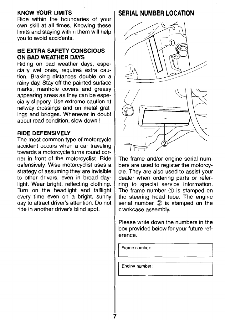
SERIAL NUMBER LOCATION
The frame andlor engine serial num-
bers are used to register the motorcycle. They are also used to assist your
dealer when ordering parts or refer-
ring to special service information.
The frame number
the steering head tube. The engine
serial number is stamped on the
crankcase assembly.
@l
is stamped on
Please write down the numbers in the
box provided below for your future ref-
erence.
Frame number:
I
Engine number:
I
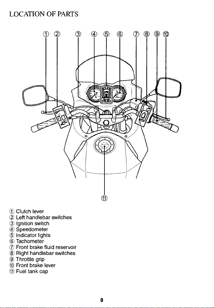
LOCATION OF PARTS
CC
Clutch lever
Q
Left handlebar switches
@
Ignition switch
@
Speedometer
Indicator lights
@
Tachometer
CE
Front brake fluid reservoir
@
Right handlebar switches
@
Throttle grip
0
Front brake lever
O
Fuel tank cap
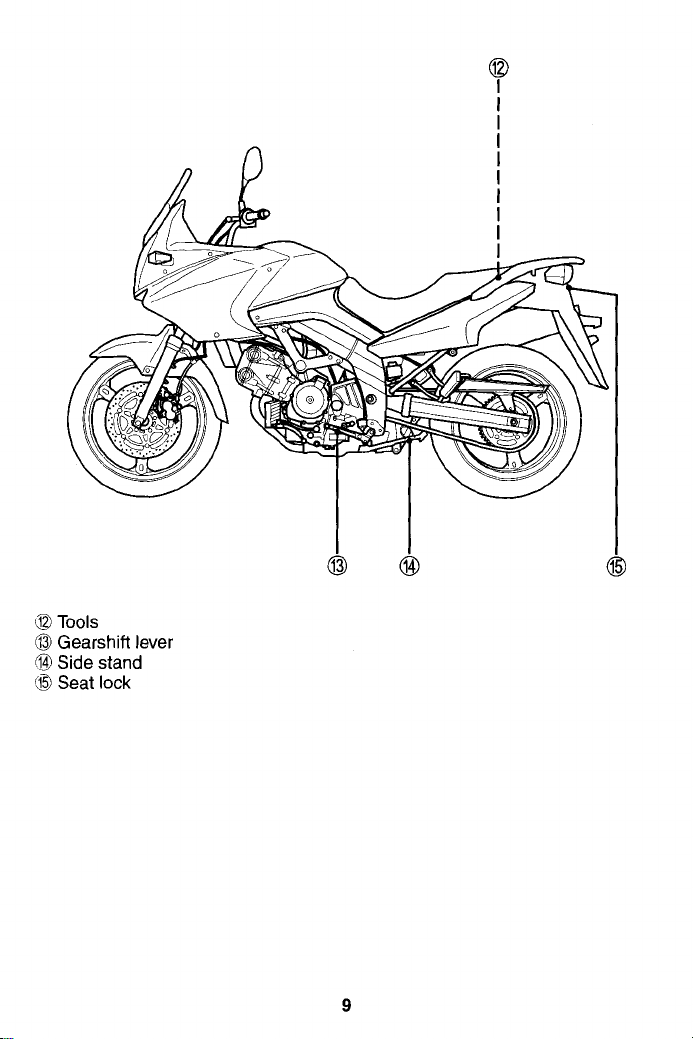
42
Tools
@l
Gearshift lever
@
Side stand
Seat lock
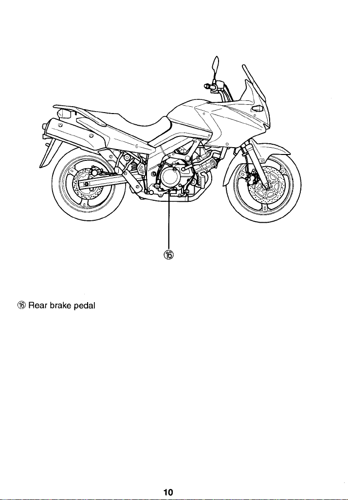
@
Rear brake pedal
CONTROLS
A6446
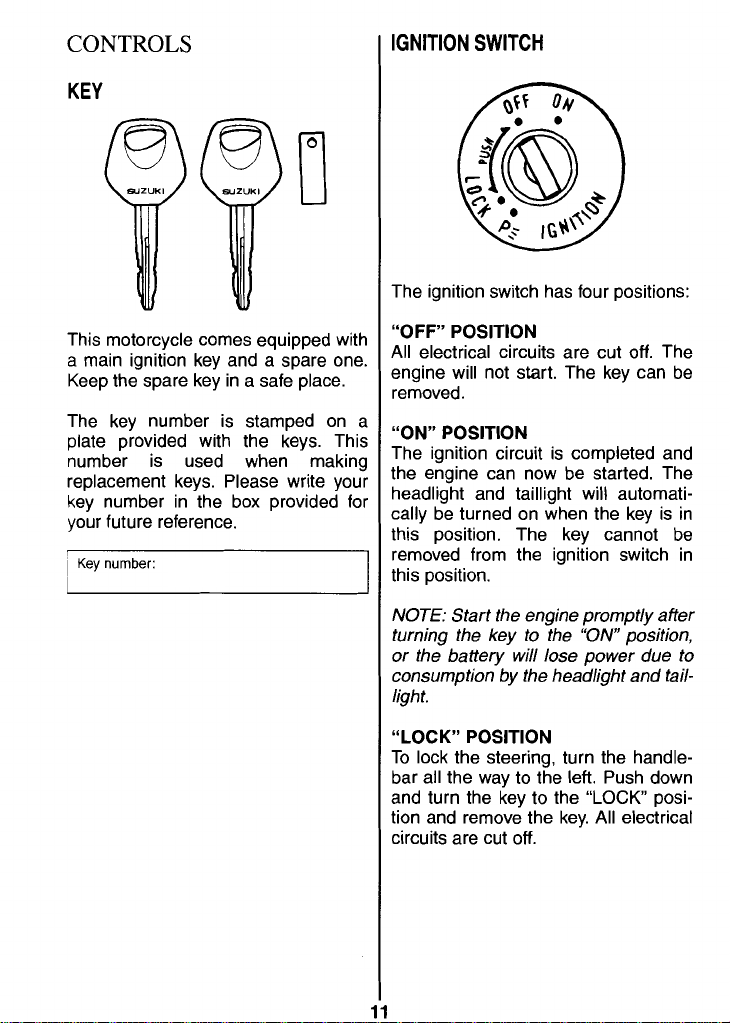
KEY
SWITCH
The ignition switch has four positions:
This motorcycle comes equipped with
a
main ignition key and a spare one.
Keep the spare key in a safe place.
The key number is stamped on a
plate provided with the keys. This
number is used when making
replacement keys. Please write your
key number in the box provided for
your future reference.
I
j
Key
number:
"OFF" POSITION
All electrical circuits are cut off. The
engine will not start. The key can be
removed.
"ON" POSITION
The ignition circuit is completed and
the engine can now be started. The
headlight and taillight will automatically be turned on when the key is in
this position. The key cannot be
removed from the ignition switch in
this position.
NOTE:
Start the engine promptly after
turning the key to the
"ON
position,
or the battery will lose power due to
consumption by the headlight and tail-
light.
"LOCK" POSITION
To lock the steering, turn the handlebar all the way to the left. Push down
and turn the key to the
tion and remove the key. All electrical
circuits are cut off.
"LOCK
posi-
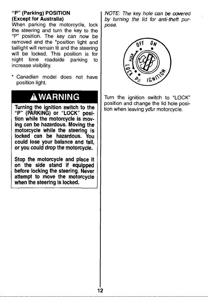
"P" (Parking) POSITION
(~xce~t for -Australia)
When parking the motorcycle, loc
the steering and turn the key to thc
"P"
position. The key can now
removed and the 'position light anc
taillight will remain lit and the steerin!
will be locked. This position is
night time roadside parking tc
increase visibility.
*
Canadian model does not havc
position light.
1
Turning the ignition switch to the
b~
fa
"P" (PARKING) or "LOCK" position while the motorcycle is moving can be hazardous. Moving the
motorcycle while the steering is
locked can be hazardous. You
could lose your balance and fall,
or you could drop the motorcycle.
Stop the motorcycle and place it
on the side stand if equipped
before locking the steering. Never
attempt to move the motorcycle
when the steering is locked.
NOTE: The key hole can
by turning the lid for anti-theft purpose.
Turn the ignition switch to "LOCK
position and change the lid hole position when leaving yc5r motorcycle.
be
covered
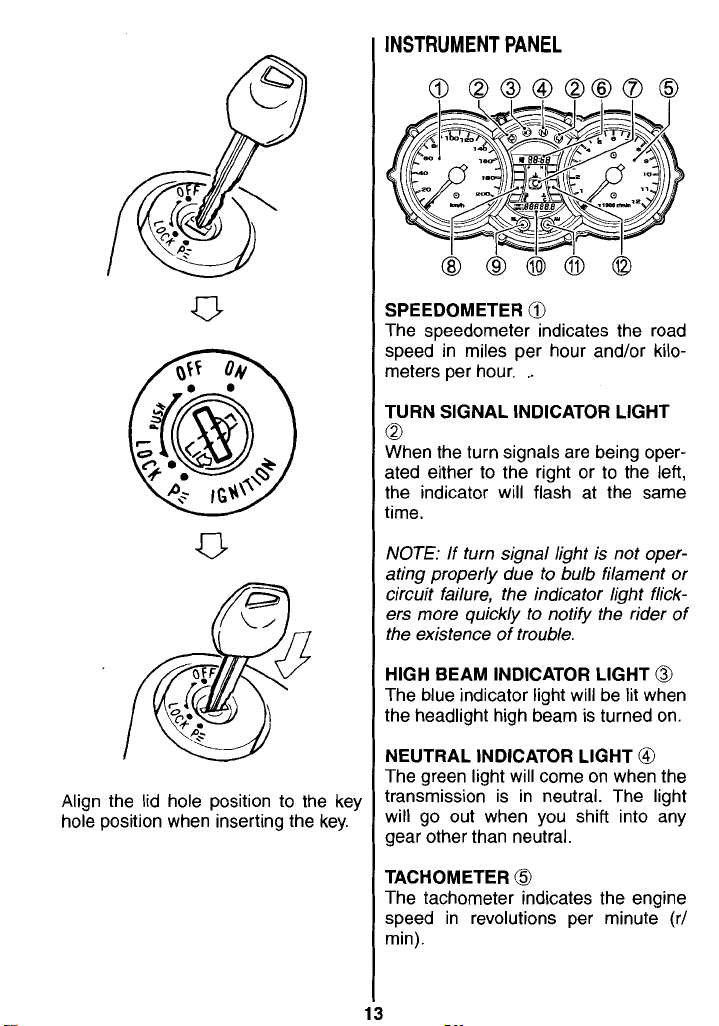
INSTRUMENT PANEL
SPEEDOMETER
The speedometer indicates the road
speed in miles per hour and/or kilometers per hour.
TURN SIGNAL INDICATOR LIGHT
,
0
When the turn signals are being operated either to the right or to the left,
the indicator will flash at the same
time.
Align the lid hole position to the key
hole position when inserting the key.
NOTE:
ating properly due to bulb filament or
circuit failure, the indicator light flickers more quickly to notify the rider of
the existence of trouble.
HIGH BEAM INDICATOR LIGHT
The blue indicator light will be lit when
the headlight high beam is turned on.
NEUTRAL INDICATOR LIGHT
The green light will come on when the
transmission is in neutral. The light
will go out when you shift into any
gear other than neutral.
TACHOMETER
The tachometer indicates the engine
speed in revolutions per minute (r/
min).
If turn signal light is not oper-
@
@
@
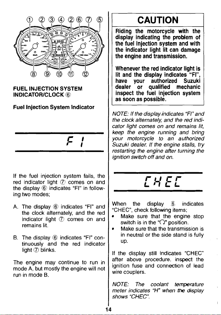
FUEL INJECTION SYSTEM
INDICATORICLOCK
@
Fuel Injection System Indicator
If the fuel injection system fails, the
red indicator light comes on and
the display
ing two modes;
A.
The display @ indicates "FI" and
the clock alternately, and the red
indicator light
remains lit.
B.
The display @ indicates "FI" continuously and the red indicator
light
The engine may continue to run in
mode
run in mode
@
indicates "FI" in follow-
Q
comes on and
Q
blinks.
A,
but mostly the engine will not
B.
1
CAUTION
Riding the motorcycle with the
display indicating the problem of
the fuel injection system and with
the indicator light lit can damage
the engine and transmission.
Whenever the red indicator light is
lit and the display indicates
"FI",
have your authorized Suzuki
dealer or qualified mechanic
inspect the fuel injection system
as soon as possible.
NOTE: If the disp1ay.indicates "F1"and
the clock alternate/)( and the red indicator light comes on and remains lit,
keep the engine running and bring
your motorcycle to an authorized
Suzuki dealer. If the engine stalls, try
restarting the engine after turning the
ignition switch off and on.
When the display
"CHEC", check following items;
Make sure that the engine stop
switch is in the
Make sure that the transmission is
in neutral or the side stand is fully
UP.
If the display still indicates 'CHEC
after above procedure. inspect the
ignition fuse and
wire couplers.
NOTE: The coolant temperature
meter indicates "H" when
shows "CHEC".
5
indicates
"C)"
position.
connectton of lead
the
dsplay
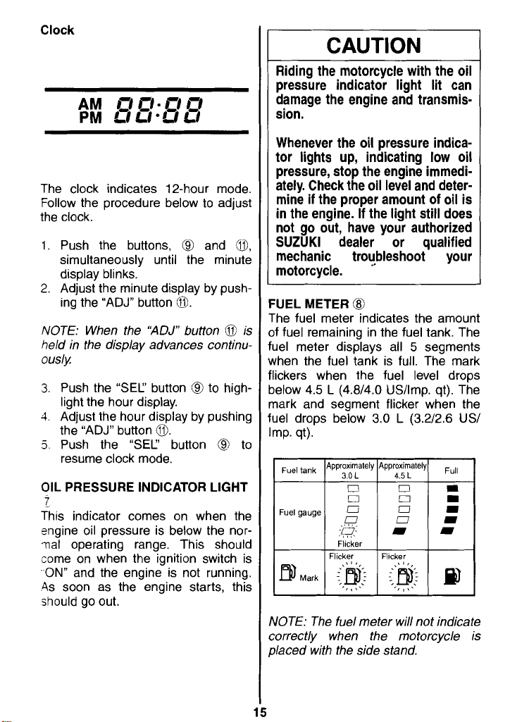
Clock
The clock indicates 12-hour mode.
Follow the procedure below to adjust
the clock.
1.
Push the buttons,
simultaneously until the minute
display blinks.
C3
and
0,
CAUTION
Riding the motorcycle with the oil
pressure indicator light lit can
damage the engine and transmission.
Whenever the oil pressure indicator lights up, indicating low oil
pressure, stop the engine immediately. Check the oil level and deter-
mine if the proper amount of oil is
in the engine. If the light still does
not go out, have your authorized
SUZUKl dealer or qualified
mechanic troubleshoot your
motorcycle.
NOTE: When the
held in the display advances continuously
3.
Push the "SEC' button @ to highlight the hour display.
1.
Adjust the hour display by pushing
the "ADJ" button
5.
Push the
resume clock mode.
OIL PRESSURE INDICATOR LIGHT
"ADJ"
a.
"SEC'
button @ is
button
@
to
t
This indicator comes on when the
sngine oil pressure is below the nor~al operating range. This should
come on when the ignition switch is
,-ON"
and the engine is not running.
4s soon as the engine starts, this
should go out.
FUEL METER
The fuel meter indicates the amount
of fuel remaining in the fuel tank. The
fuel meter displays all 5 segments
when the fuel tank is full. The mark
flickers when the fuel level drops
below 4.5
mark and segment flicker when the
fuel drops below 3.0
Imp. qt).
NOTE: The fuel meter will not indicate
correctly when the motorcycle is
placed with the side stand.
@
L
(4.814.0 US/lmp. qt). The
L
(3.212.6 US1
I
Flicker
l
Flicker l Flicker
I
I
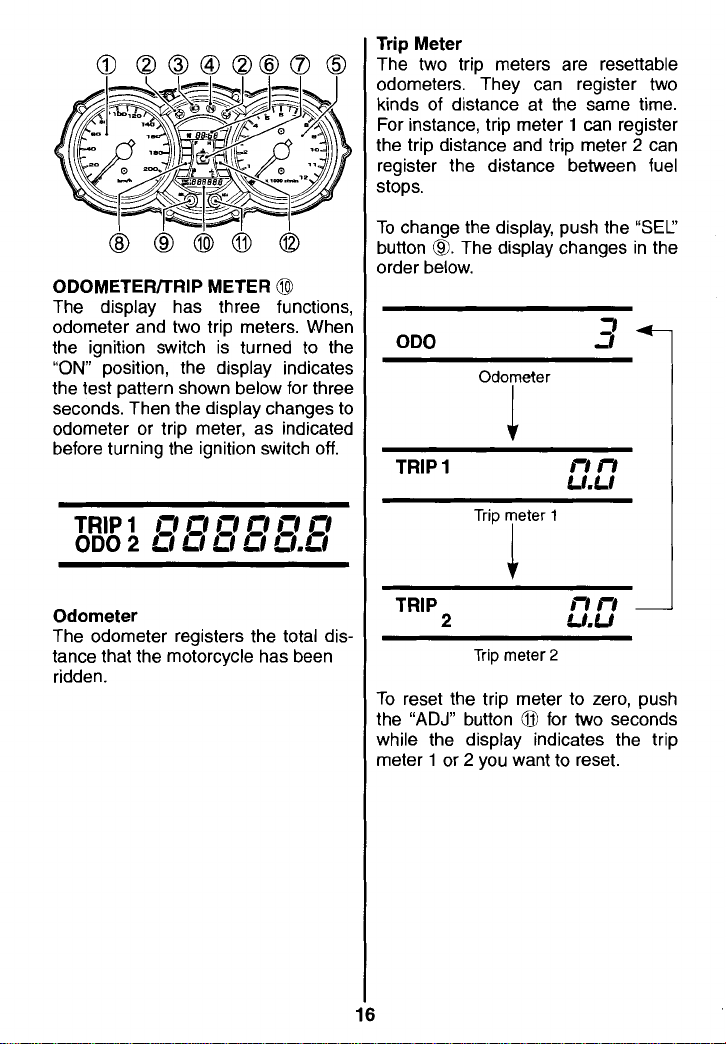
Trip Meter
The two trip meters are resettable
odometers. They can register two
kinds of distance at the same time.
For instance, trip meter 1 can register
the trip distance and trip meter
register the distance between fuel
stops.
2
can
ODOMETERITRIP METER
The display has three functions,
odometer and two trip meters. When
the ignition switch is turned to the
"ON"
position, the display indicates
the test pattern shown below for three
seconds. Then the display changes to
odometer or trip meter, as indicated
before turning the ignition switch off.
TRIP
1
I=!
I~I
ODO
2
CI Cl LI
Odometer
The odometer registers the total distance that the motorcycle has been
ridden.
I=!
@
rI EI rI
a
LI.CI
To change the display, push the
button
@.
order below.
ODO
The display changes in the
Odometer
"SEC'
l
TRIP
1
TRIP
2
Trip meter
To reset the trip meter to zero, push
"ADJ"
the
while the display indicates the trip
meter
button O for two seconds
1
or 2 you want to reset.
2
16
Operating the display while riding
can be hazardous. Removing a
hand from the handlebars can
reduce your ability to control the
motorcycle.
Always keep both hands on the
handlebars while riding.
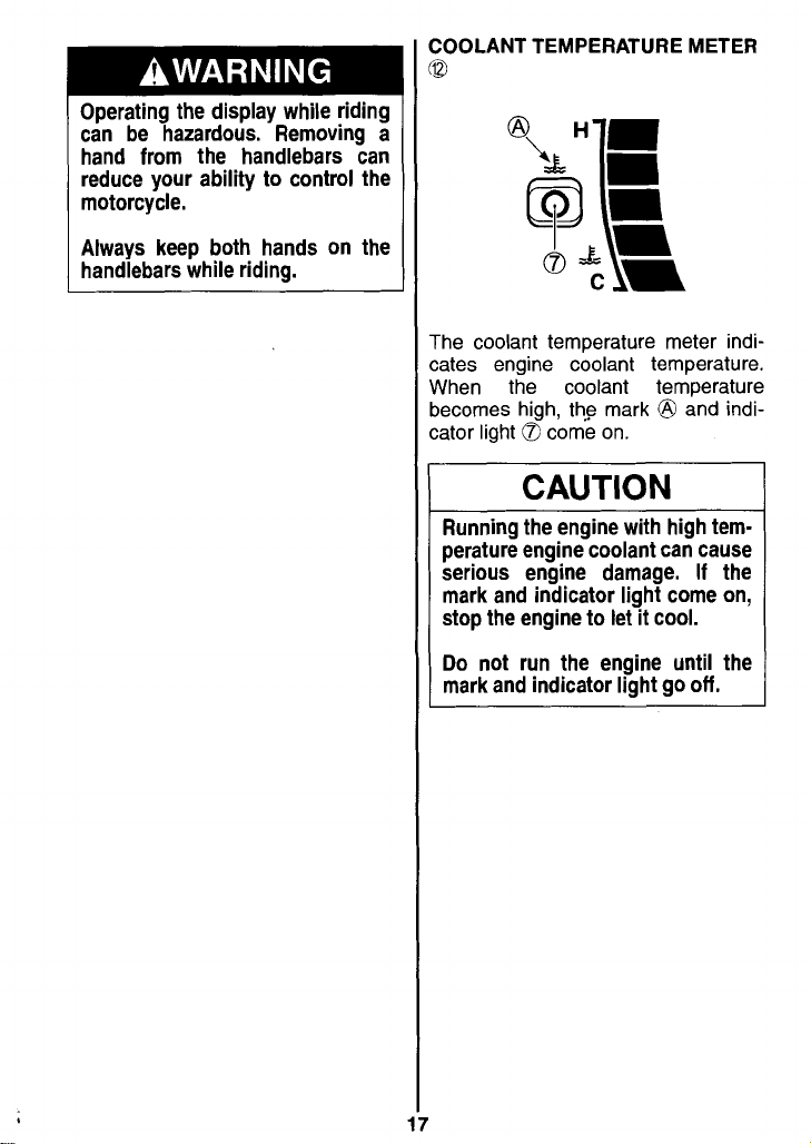
The coolant temperature meter indicates engine coolant temperature.
When the coolant temperature
becomes high, th? mark
cator light
1
Running the engine with high temperature engine coolant can cause
serious engine damage. If the
mark and indicator light come on,
stop the engine to let it cool.
Do not run the engine until the
mark and indicator light go off.
Q
come on.
CAUTION
-
@
-
and indi-
LEFT HANDLEBAR
IORN SWITCH
'ress the switch to sound the horn.
"b"
5
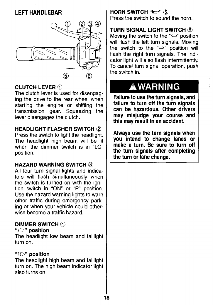
CLUTCH LEVER
The clutch lever is used for disengaging the drive to the rear wheel when
starting the engine or shifting the
transmission gear. Squeezing the
lever disengages the clutch.
HEADLIGHT FLASHER SWITCH
Press the switch to light the headlight.
The headlight high beam will be lit
when the dimmer switch is in
position.
HAZARD WARNING SWITCH
All four turn signal lights and indicators will flash simultaneously when
the switch is turned on with the ignition switch in
Use the hazard warning lights to warn
other traffic during emergency parking or when your vehicle could otherwise become a traffic hazard.
@
"ON"
or "P" position.
Q
"LO"
@
URN SIGNAL LIGHT SWITCH
loving the switch to the
fill flash the left turn signals. Moving
le switch to the
ash the right turn signals. The indiator light will also flash intermittently.
D
cancel turn signal operation, push
ie switch in.
'a"
"0"
@
position
position will
Failure to use the turn signals, and
failure to turn off the turn signals
can be hazardous. Other drivers
may misjudge your course and
this may result in an accident.
Always use the turn signals when
you intend to change lanes or
make a turn. Be sure to turn off
the turn signals after completing
the turn or lane change.
DIMMER SWITCH
"LO"
position
The headlight low beam and taillight
turn on.
":D"
position
The headlight high beam and taillight
turn on. The high beam indicator light
also turns on.
@
RIGHT HANDLEBAR
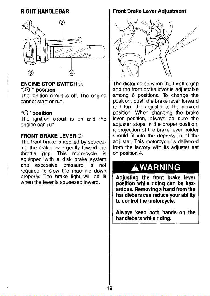
ENGINE STOP SWITCH
"ZX"
position
The ignition circuit is off. The engine
cannot start or run.
"C)"
position
The ignition circuit is on and the
engine can run.
FRONT BRAKE LEVER
The front brake is applied by squeez-
ing the brake lever gently toward the
throttle grip. This motorcycle is
equipped with a disk brake system
and excessive pressure is not
required to slow the machine down
properly. The brake light will be lit
when the lever is squeezed inward.
@
@l
Front Brake Lever
/
T
'he distance between the throttle grip
a
nd the front brake lever is adjustable
a
mong
6
positions. To change the
osition, push the brake lever forward
P
nd turn the adjuster to the desired
a
osition. When changing the brake
P
I€
?ver position, always be sure the
djuster stops in the proper position;
a
projection of the brake lever holder
a
hould fit into the depression of the
S
djuster. This motorcycle is delivered
a
fr
,om the factory with its adjuster set
n position
4.
S
Adjustment
Adjusting the front brake lever
position while riding can be haz-
ardous. Removing a hand from the
handlebars can reduce your ability
to control the motorcycle.
Always keep both hands on the
handlebars while riding.

THROlTLE GRIP
Engine speed is controlled by the
position of the throttle grip. Twist it
toward you to increase engine speed.
Turn it away from you to decrease the
engine speed.
~
@l
ELECTRIC STARTER BUlTON
"a'
0
This button is used for operating th
starter motor. With the ignition switc
"ON"
in the
switch in
neutral, push the electric starter bu
ton to operate the starter motor an
start the engine.
NOTE: This motorcycle is equippe
with interlock switches for the ignitio
circuit and the starter circuit. Th
engine can only be started if:
The transmission is in neutral an
the clutch is disengaged, or
The transmission is in gear, th
side stand is fully up and th
clutch is disengaged.
position, the engine sto
"C)" and the transmission i
CAUTION
To prevent electrical system damage, do not operate the starter
motor more than five seconds at a
time.
If the engine does not start after
several attempts, check the fuel
supply and ignition system. Refer
to the TROUBLESHOOTING section in this manual.
3
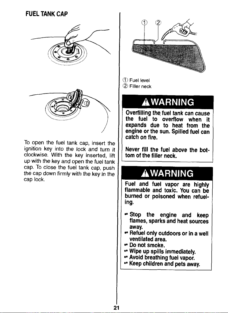
FUEL
TANK
CAP
To open the fuel tank cap, insert the
ignition key into the lock and turn it
clockwise. With the key inserted,
up with the key and open the
cap. To close the fuel tank cap, push
the cap down firmly with the key in the
cap lock.
lift
fuel tank
D
Fuel level
a
Filler neck
Overfilling the. fuel tank can cause
the fuel to overflow when it
expands due to heat from the
engine or the sun. Spilled fuel can
catch on fire.
Never fill the fuel above the bot-
tom of the filler neck.
Fuel and fuel vapor are highly
flammable and toxic. You can be
burned or poisoned when
refuel-
ing.
Stop the engine and keep
flames, sparks and heat sources
away.
Refuel only outdoors or in a well
ventilated area.
Do not smoke.
Wipe up spills immediately.
Avoid breathing fuel vapor.
Keep children and pets away.
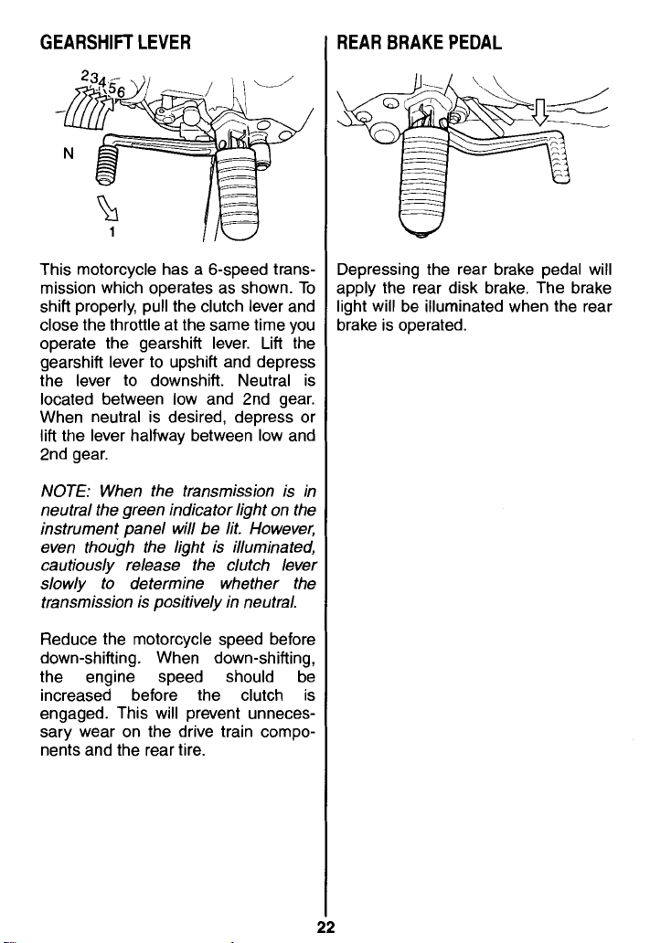
GEARSHIFT LEVER
REAR BRAKE PEDAL
This motorcycle has a 6-speed trans-
mission which operates as shown. To
shift properly, pull the clutch lever and
close the throttle at the same time you
operate the gearshift lever. Lift the
gearshift lever to
the lever to downshift. Neutral is
located between low and 2nd gear.
When neutral is desired, depress or
lift the lever halfway between low and
2nd gear.
NOTE:
neutral the green indicator light on the
instrument panel will be lit. However,
even though the light is illuminated,
cautiously release the clutch lever
slowly to determine whether the
transmission is positively in neutral.
Reduce the motorcycle speed before
down-shifting. When down-shifting,
the engine speed should be
increased before the clutch is
engaged. This will prevent unnecessary wear on the drive train compo-
nents and the rear tire.
When the transmission is in
upshift and depress
Depressing the rear brake pedal will
apply the rear disk brake. The brake
light will be illuminated when the rear
brake is operated.
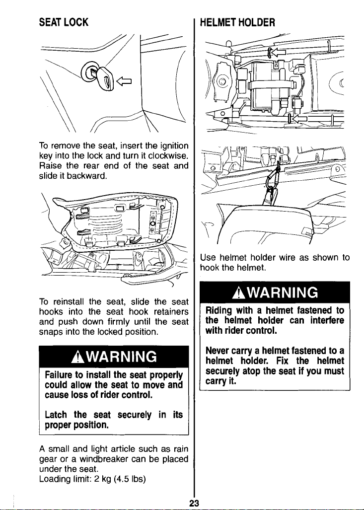
SEAT LOCK
HELMET HOLDER
To remove the seat, insert the ignitior
key into the lock and turn it clockwise
Raise the rear end of the seat
slide it backward.
To reinstall the seat, slide the sea
hooks into the seat hook retainer!
and push down firmly until the sea
snaps into the locked position.
Failure to install the seat properly
could allow the seat to move and
cause loss of rider control.
Latch the seat securely in its
proper position.
an(
l
;
1
,
-
\I
-
U
Ise helmet holder wire as shown to
ook the helmet.
Riding with a helmet fastened to
the helmet holder can interfere
with rider control.
Never carry a helmet fastened to a
helmet holder.
securely atop the seat if you must
carry it.
Fix
the helmet
A
small and light article such as rair
gear or a windbreaker can be place(
under the seat.
Loading limit:
2
kg
(4.5
Ibs)
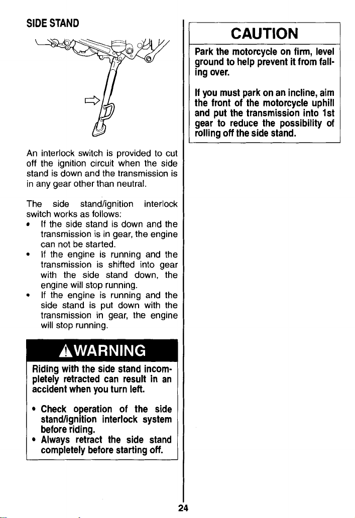
SIDE STAND
An interlock switch is provided to cu
off the ignition circuit when the sidc
stand is down and the transmission i:
in any gear other than neutral.
CAUTION
Park the motorcycle on firm, level
it
ground to help prevent
ing over.
If you must park on an incline, aim
the front of the motorcycle uphill
and put the transmission into 1st
gear to reduce the possibility of
rolling off the side stand.
from fall-
The side
switch works as follows:
If the side stand is down and thf
transmission is in gear, the enginf
can not be started.
If the engine is running and thf
transmission is shifted into gea
with the side stand down,
engine will stop running.
If the engine is running and thf
side stand is put down with thf
transmission in gear, the enginf
will stop running.
standfignition interlocl
Riding with the side stand incompletely retracted can result in an
accident when you turn left.
Check operation of the side
standlignition interlock system
before riding.
Always retract the side stand
completely before starting off.
thf
 Loading...