

Page 1

Notice Originale
F
Original Instructions
Originalbetriebsanleitung
TTF
A LIRE ATTENTIVEMENT AVANT D’UTILISER LA MACHINE
PLEASE READ CAREFULLY BEFORE USING THE MACHINE
VOR INBETRIEBNAHME SORGFÄLTIG LESEN!
Réf: 400 580-00 - FR-GB-DE /TF
Les Portes de Bretagne
P.A. de la Gaultière – 35220 CHATEAUBOURG France
Tél :(33)02-99-00-84-84 · Fax : (33)02-99-62-39-38
Site Internet : www.sulky-burel.com
E-Mail : info@sulky-burel.com
Adresse postale
SULKY-BUREL – CS 20005 – 35538 NOYAL SUR VILAINE CEDEX France
Page 2

Page 3
Cher Utilisateur / Dear Customer / Geehrter Kunde
le bon de Ga-
rantie dûment rempli
J. BUREL
Cher Client,
Vous avez choisi le SEMOIR à grains XEOS TF, et nous
vous remercions de votre confiance pour notre matériel.
Pour une bonne utilisation, et pour tirer profit de toutes
les capacités de votre semoir, nous vous recommandons
de lire attentivement cette notice.
De par votre expérience, n’hésitez pas à nous faire part
de vos observations et suggestions, toujours utiles pour
l’amélioration de nos produits.
Nous vous saurions gré de nous retourner
.
En vous souhaitant bon usage de votre semoir,
Veuillez agréer, Cher Client, l’assurance de nos meilleurs
sentiments.
Président
GB
Dear Customer,
Thank you for choosing the XEOS TF seed
drill.
To ensure correct operation, and to get the
most out of your seed drill, we recommend
that you read these instructions carefully.
Please do not hesitate to give us your suggestions and comments based on your experience. They are always useful for
improving our products.
We would be grateful if you could return
the duly completed guarantee coupon.
We hope your seed drill will provide long
and trouble-free service.
Yours sincerely.
DE
Geehrter Kunde,
Sie haben eine XEOS TF-Drillmaschine gewählt, und wir danken Ihnen für das in unsere Geräte gesetzte Vertrauen.
Bitte lesen Sie die Anleitung sorgfältig
durch, damit Sie ihre Drillmaschine richtig
benutzen und alle ihre Möglichkeiten voll
nutzen können.
Zögern Sie nicht, uns Ihre eigenen Beobachtungen und Erfahrungen mitzuteilen,
die für die Verbesserung unserer Produkte
immer nützlich sein können.
Garantieschein bitte ausgefüllt an uns zurückschicken.
Wir wünschen Ihnen viel Erfolg mit Ihrem
Drillmaschine und verbleiben
J. BUREL
Chairman
mit freundlichen Grüßen
J. BUREL
Präsident
1
Page 4

Selon annexe 2, partie 1, point A de la directive « MACHINES » 2006/42/CE.
In accordance with Appendix 2, Section 1, Point A of the European Machinery Directive 2006/42/EC.
Gemäß Anhang II, Teil 1, Abschnitt A der Maschinenrichtlinie 2006/42/EG.
Déclaration de Conformité
Declaration of Conformity
Konformitätserklärung
NOM DU FABRICANT ET ADRESSE :
MANUFACTURER’SNAMEANDADDRESS:
NAME UND ADRESSE DES HERSTELLERS:
NOM DE LA PERSONNE AUTORISÉE A
CONSTITUER LE DOSSIER TECHNIQUE ET ADRESSE :
NAME AND ADDRESS OF THE PERSON AUTHORISED
TO COMPILE TH E TECHNICAL SPECIFICATIONS:
NAME UND ADRESSE DES FÜR DIE ZUSAMMENSTELLUNG DER
TECHNISCHEN UNTERLAGEN BEVOLLMÄCHTIGTEN:
DESCRIPTION DE LA MACHINE :
MACHINE DESCRIPTION :
BESCHREIBUNG DER MASCHINE:
TYPE :
TYPE:
TYP:
NUMÉRO DE SÉRIE :
SERIAL NUMBER:
S
ERIENNUMMER:
SULKY-BUREL
PA DE LA GAULTIÈRE
35220 CHATEAUBOURG FRANCE
ULIEN
J
J
ULIEN
BUREL
BUREL
PA DE LA GAULTIÈRE
35220 CHATEAUBOURG FRANCE
SEMOIR À GRAINS
SEMOIR À GRAINS
SEED DRILL
SEED DRILL
DRILLMASCHINE
DRILLMASCHINE
XEOS TF
ACCESSOIRES :
A
CCESSORIES:
ZUSATZAUSRÜSTUNGEN:
FR
LA MACHINE EST CONFORME AUX
DISPOSITIONS PERTINENTES DE LA
DIRECTIVE
A MACHINE EST CONFORME AUX
L
DISPOSITIONS DES AUTRES DIRECTIVES
SUIVANTES
D
IRECTIVE CEM 2004 / 108 / CE
Fait à Châteaubourg : Mars 2012
Châteaubourg: March 2012
Ausgestellt in Châteaubourg: März 2012
2
« MACHINES » 2006-42 CE
:
T
HE MACHINE CONFORMS TO THE
RELEVANT TERMS OF THE
EUROPEAN
MACHINERY DIRECTIVE 2006/42/EC.
HE MACHINE ALSO CONFORMS TO THE
T
TERMS OF THE FOLLOWING DIRECTIVES
D
IRECTIVE EMC 2004/108/EC
GB
:
D
IE MASCHINE ENTSPRICHT ALLEN
EINSCHLÄGIGEN
BESTIMMUNGEN DER
MASCHINENRICHTLINIE 2006/42/EG
IE MASCHINE ENTSPRICHT
D
BESTIMMUNGEN
DEN
DER NACHFOLGENDEN
EMV-R
ICHTLINIE 2004/108/EG
RICHTLINIEN:
Signé :
Signed:
Unterzeichnet:
J. BUREL
Président
Chairman
Präsident
DE
Page 5

PRESCRIPTIONS GÉNÉRALES DE SÉCURITÉ
GÉNÉRALITÉS
UTILISATION CONFORME DE LA MACHINE
ATTELAGE
Prescriptions de sécurité
FR
Attention
charge utile
Danger
pièces en mouvement
ne pas s’approcher
Ces symboles sont utilisés dans cette notice chaque fois que des recommandations concernent votre sécurité, celle d’autrui ou le bon
fonctionnement de la machine.
Transmettez impérativement ces recommandations à tout utilisateur de la machine.
Avant chaque utilisation et mise en service de l’ensemble tracteur-machine, s’assurer de sa conformité avec la réglementation en matière de sécurité
du travail et avec les dispositions du Code de la
Route.
1 - Respecter, en plus des instructions contenues
dans cette notice, la législation relative aux prescriptions de sécurité et de prévention des accidents.
2 - Les avertissements apposés sur la machine
fournissent des indications sur les mesures de sécurité à observer et contribuent à éviter les accidents.
3 - Lors de la circulation sur la voie publique, respecter les prescriptions du Code de la Route.
4 - Avant de commencer le travail, l’utilisateur
devra se familiariser obligatoirement avec les organes de commande et de manœuvre de la machine et leurs fonctions respectives. En cours de
travail, il sera trop tard pour le faire.
5 - L’utilisateur doit éviter de porter des vêtements
flottants qui risqueraient d’être happés par des éléments en mouvement.
6 - Il est recommandé d’utiliser un tracteur équipé
d’une cabine ou d’un arceau de sécurité, aux
normes en vigueur.
7 - Avant la mise en route de la machine et le démarrage des travaux, contrôler les abords immédiats (enfant !).
Veiller à avoir une visibilité suffisante ! Eloigner
toute personne ou animal de la zone de danger de
la machine (projections !).
8 - Le transport de personnes ou d’animaux sur la
machine lors du travail ou lors des déplacements
est strictement interdit.
9 - L’accouplement de la machine au tracteur ne
doit se faire que sur les points d’attelage prévus à
cet effet conformément aux normes de sécurité en
vigueur.
10 - La prudence est de rigueur lors de l’attelage
de la machine au tracteur et lors de son désaccouplement !
11 - Avant d’atteler la machine, il conviendra de
s’assurer que le lestage de l’essieu avant du tracteur est suffisant. La mise en place des masses de
lestage doit se faire sur les supports prévus à cet
effet conformément aux prescriptions du constructeur du tracteur.
12 - Respecter la charge à l’essieu maximum et le
poids total roulant autorisé en charge.
13 - Respecter le gabarit maximum sur la voie publique.
14 - Avant de s’engager sur la voie publique, veil-
à ne pas dépasser
ler à la mise en place et au bon fonctionnement
des protecteurs et dispositifs de signalisation (lumineux, réfléchissants…) exigés par la loi. Remplacer les ampoules grillées par des types et couleurs
identiques.
15 - Toutes les commandes à distance (corde,
câble, tringle, flexible…) doivent être positionnées
de telle sorte qu’elles ne puissent déclencher accidentellement une manœuvre génératrice de risque
d’accident ou de dégâts.
16 - Avant de s’engager sur la voie publique, placer la machine en position de transport, conformément aux indications du constructeur.
17 - Ne jamais quitter le poste de conduite lorsque
le tracteur est en marche.
18 - La vitesse et le mode de conduite doivent
toujours être adaptés aux terrains, routes et chemins. En toute circonstance, éviter les brusques
changements de direction.
19 - La précision de la direction, l’adhérence du
tracteur, la tenue de route et l’efficacité des dispositifs de freinage sont influencées par des facteurs
tels que : poids et nature de la machine attelée,
lestage de l’essieu avant, état du terrain ou de la
chaussée. Il est donc impératif de veiller au respect
des règles de prudence dictées par chaque situation.
20 - Redoubler de prudence dans les virages en
tenant compte du porte-à-faux, de la longueur, de
la hauteur et du poids de la machine ou de la remorque attelée.
21 - Avant toute utilisation de la machine, s’assurer que tous les dispositifs de protection sont en
place et en bon état. Les protecteurs endommagés
doivent être immédiatement remplacés.
22 - Avant chaque utilisation de la machine,
contrôler le serrage des vis et des écrous, en particulier de ceux qui fixent les outils (disques, palettes, déflecteurs…). Resserrer si nécessaire.
23 - Ne pas stationner dans la zone de manœuvre
de la machine.
24 - Attention ! Des zones d’écrasement et de cisaillement peuvent exister sur les organes commandés à distance, notamment ceux asservis
hydrauliquement.
25 - Avant de descendre du tracteur, ou préalablement à toute intervention sur la machine, couper le
moteur, retirer la clé de contact et attendre l’arrêt
complet de toutes les pièces en mouvement.
26 - Ne pas stationner entre le tracteur et la machine sans avoir préalablement serré le frein de
parcage et/ou avoir placé des cales sous les roues.
27 - Avant toute intervention sur la machine, s’assurer que celle-ci ne puisse être mise en route accidentellement.
28 - Ne pas utiliser l’anneau de levage pour lever
la machine lorsqu’elle est remplie.
Risque
d’endommager
la machine
Risque
d’accident
Faciliter le
travail
Risque d’endommagement
de la machine
consulter la notice
Le Semoir ne doit être utilisé que pour les travaux
pour lesquels il a été conçu.
En cas de dommage lié à l’utilisation de la machine
hors du cadre des applications spécifiées par le
constructeur, la responsabilité de celui-ci sera entièrement dégagée.
Toute extrapolation de la destination d’origine de la
machine se fera aux risques et périls de l’utilisateur.
L’utilisation conforme de la machine implique également :
- le respect des prescriptions d’utilisation, d’entretien et de maintenance édictées par le constructeur,
- l’utilisation exclusive de pièces de rechange,
d’équipements et d’accessoires d’origine ou préconisés par le constructeur.
Le Semoir ne doit être utilisé, entretenu et réparé
que par des personnes compétentes, familiarisées
avec les caractéristiques et modes d’utilisation de
la machine. Ces personnes doivent aussi être informées des dangers auxquels elles pourraient être
exposées.
L’utilisateur est tenu au respect scrupuleux de la
réglementation en vigueur en matière de :
- prévention contre les accidents,
- sécurité du travail (Code du Travail),
- circulation sur la voie publique (Code de la
Route).
- Il lui est fait obligation d’observer strictement les
avertissements apposés sur la machine.
- Toute modification de la machine effectuée par
l’utilisateur lui-même ou toute autre personne,
sans l’accord écrit préalable du constructeur engagera la responsabilité du propriétaire du matériel
modifié.
- La valeur d'émission de bruit mesurée au poste
de conduite cabine fermée. (Niveau de pression
acoustique) est de 75 dB(A)
Appareil de mesure : SL 401
Position du microphone positionné selon le paragraphe B.2.6 de l’annexe B de la NF EN ISO 4254-1.
Ce niveau de pression acoustique dépend, pour
l'essentiel, du tracteur utilisé.
1 - Lors de l’attelage de la machine au tracteur ou
de sa dépose, placer le levier de commande du relevage hydraulique dans une position telle que
toute entrée en action du relevage ne puisse intervenir de façon inopinée.
2 - Lors de l’attelage de la machine au relevage 3
points du tracteur, veiller à ce que les diamètres
des broches ou tourillons correspondent bien aux
diamètres des rotules du tracteur.
3
Page 6
FR
3 - Attention ! Dans la zone de relevage 3 points, il
existe des risques d’écrasement et de cisaillement!
4 - Ne pas se tenir entre le tracteur et la machine
lors de la manœuvre du levier de commande extérieur du relevage.
5 - Au transport la machine doit être stabilisée par
les tirants de rigidification du relevage pour éviter
tout flottement et débattement latéral.
6 - Lors du transport de la machine en position relevée, verrouiller le levier de commande du relevage.
7 - Ne jamais dételer la machine lorsque la trémie
est remplie.
ORGANES D’ANIMATION
(Prises de force et arbres de transmission à cardans)
1 - N’utiliser que les arbres de transmission à cardans fournis avec la machine ou préconisés par le
constructeur.
2 - Les protecteurs des prises de force et des arbres de transmission à cardans doivent toujours
être en place et en bon état.
3 - Veiller au recouvrement correct des tubes des
arbres de transmission à cardans, aussi bien en position de travail qu’en position de transport.
4 - Avant de connecter ou de déconnecter un
arbre de transmission à cardans, débrayer la prise
de force, couper le moteur et retirer la clé de
contact.
5 - Si l’arbre de transmission à cardans primaire
est équipé d’un limiteur de couple ou d’une roue
libre, ceux-ci doivent impérativement être montés
sur la prise de force de la machine.
6 - Veiller toujours au montage et au verrouillage
corrects des arbres de transmission à cardans.
7 - Veiller toujours à ce que les protecteurs des arbres de transmission à cardans soient immobilisés
en rotation à l’aide des chaînettes prévues à cet
effet.
8 - Avant d’embrayer la prise de force, s’assurer
que le régime choisi et le sens de rotation de la
prise de force sont conformes aux prescriptions du
constructeur.
9 - Avant d’embrayer la prise de force, s’assurer
qu’aucune personne ou animal ne se trouve à
proximité de la machine.
10 - Débrayer la prise de force lorsque les limites
de l’angle de l’arbre de transmission à cardans
prescrites par le constructeur risquent d’être dépassées.
11 - Attention ! Après le débrayage de la prise de
force, les éléments en mouvement peuvent continuer à tourner quelques instants encore. Ne pas
s’en approcher avant immobilisation totale.
12 - Lors de la dépose de la machine, faire reposer
les arbres de transmission à cardans sur les supports prévus à cet effet.
13 - Après avoir déconnecté l’arbre de transmission à cardans de la prise de force du tracteur,
celle-ci doit être recouverte de son capuchon protecteur.
14 - Les protecteurs de prise de force et d’arbres
de transmission à cardans endommagés doivent
être remplacés immédiatement.
CIRCUIT HYDRAULIQUE
1 - Attention ! Le circuit hydraulique est sous pres-
sion.
2 - Lors du montage de vérins ou de moteurs hydrauliques, veiller attentivement au branchement
correct des circuits, conformément aux directives
du constructeur.
3 - Avant de brancher un flexible au circuit hydraulique du tracteur, s’assurer que les circuits côté
tracteur et côté machine ne sont pas sous pression.
4 - Il est vivement recommandé à l’utilisateur de la
machine de suivre les repères d’identification sur
les raccords hydrauliques entre le tracteur et la
machine afin d’éviter des erreurs de branchement.
Attention ! Il y a risque d’interversion des fonctions
(par exemple : relever/abaisser).
5 - Contrôler une fois par an les flexibles hydrauliques :
. Blessure de la couche extérieure
. Porosité de la couche extérieure
. Déformation sans pression et sous pression
. Etat des raccords et des joints
La durée d’utilisation maximum des flexibles est de
6 ans. Lors de leur remplacement, veiller à n’utiliser
que des flexibles de caractéristiques et de qualité
prescrits par le constructeur de la machine.
6 - Lors de la localisation d’une fuite, il conviendra
de prendre toute précaution visant à éviter les accidents.
7 - Tout liquide sous pression, notamment l’huile
du circuit hydraulique, peut perforer la peau et occasionner de graves blessures ! En cas de blessure,
consulter de suite un médecin ! Il y a danger d’in-
fection !
8 - Avant toute intervention sur le circuit hydraulique, abaisser la machine, mettre le circuit hors
pression, couper le moteur et retirer la clé de
contact.
ENTRETIEN
1 - Avant tous travaux de maintenance, d’entretien
ou de réparation, ainsi que lors de la recherche de
l’origine d’une panne ou d’un incident de fonctionnement, il faut impérativement que la prise de
force soit débrayée, que le moteur soit coupé et la
clé de contact retirée.
2 - Contrôler régulièrement le serrage des vis et
des écrous. Resserrer si nécessaire !
3 - Avant de procéder à des travaux d’entretien sur
une machine en position relevée, étayer celle-ci à
l’aide d’un moyen approprié.
4 - Lors du remplacement d’une pièce travaillante,
(pale pour les distributeurs ou socs pour les semoirs), mettre des gants de protection et n’utiliser
qu’un outillage approprié.
5 - Pour la protection de l’environnement, il est interdit de jeter ou de déverser les huiles, graisses et
filtres en tout genre. Les confier à des entreprises
spécialisées dans leur récupération.
6 - Avant toute intervention sur le circuit électrique, déconnecter la source d’énergie.
7 - Les dispositifs de protection susceptibles d’être
exposés à une usure doivent être contrôlés régulièrement. Les remplacer immédiatement s’ils sont
endommagés.
8 - Les pièces de rechange doivent répondre aux
normes et caractéristiques définies par le
constructeur. N’utiliser que des pièces de rechange
Sulky !
9 - Avant d’entreprendre des travaux de soudure
électrique sur le tracteur ou la machine attelée, débrancher les câbles de l’alternateur et de la batterie.
10 - Les réparations affectant les organes sous
tension ou pression (ressorts, accumulateurs de
pression, etc,) impliquent une qualification suffisante et font appel à un outillage spécifique ; aussi
ne doivent-elles être effectuées que par un personnel qualifié.
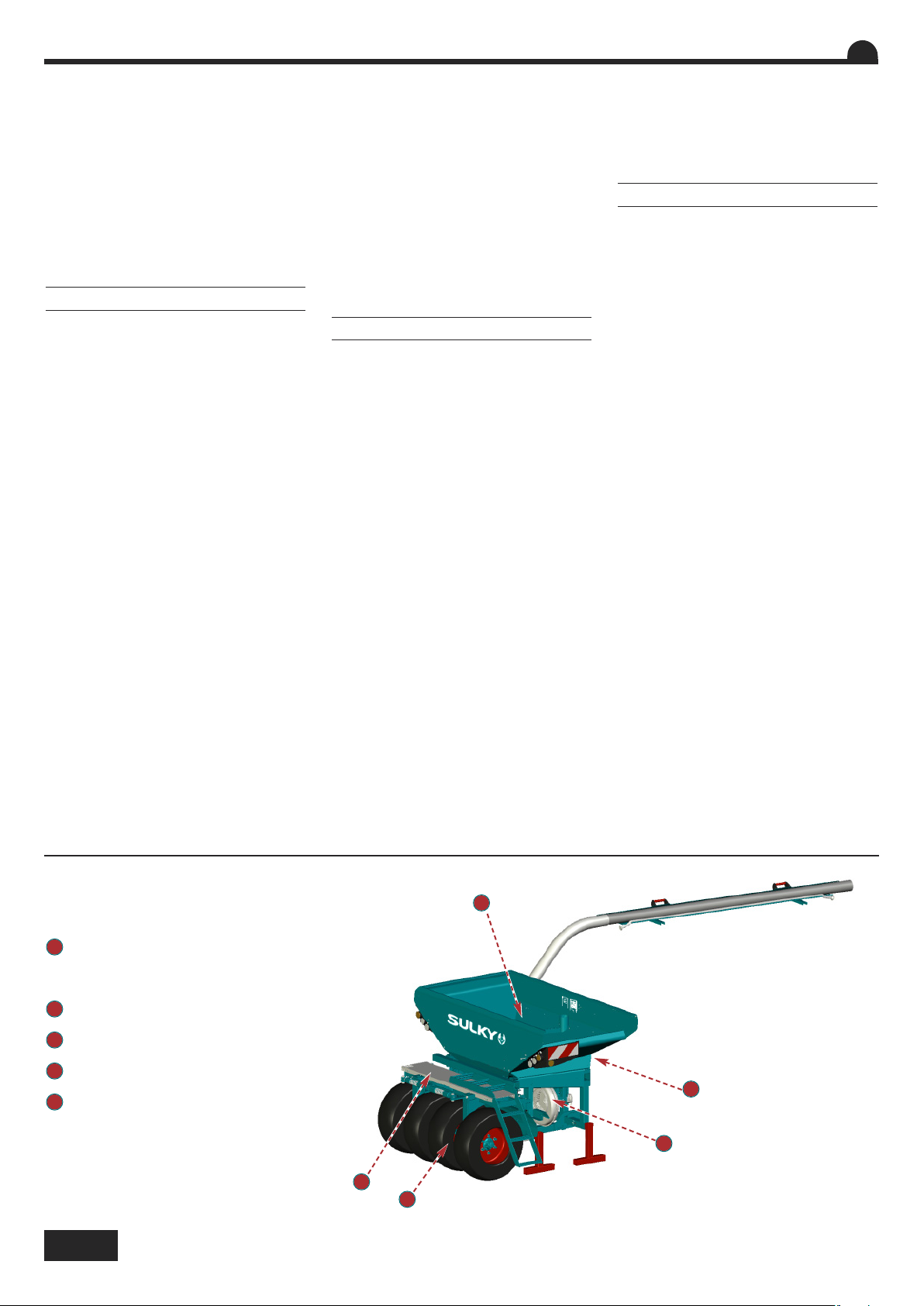
DANGER
1
Arbre en rotation
Agitateur dans la trémie
Cardan de transmission
2
Turbine en rotation
3
Risque d’écrasement attelage triangle
4
Ne pas stationner sur la passerelle
5
Pièces en mouvement
4
1
3
2
4
5
Page 7

GENERAL SAFETY REGULATIONS
GENERAL
PROPER USE OF THE MACHINE
HITCHING
Safety regulations
GB
Caution
Payload should
Danger
Moving parts,
keep away
These symbols are used in these instructions every time recommendations are provided concerning your safety, the safety of others or the cor-
rect operation of the machine.
These recommendations must be given to all users of the machine.
Every time the tractor/machine assembly is to be
started up and used, you should ensure beforehand that it complies with current legislation on safety at work and Road Traffic regulations.
1 - In addition to the instructions contained in this
manual, legislation relating to safety instructions
and accident prevention should be complied with.
2 - Warnings affixed to the machine give indications regarding safety measures to be observed
and help to avoid accidents.
3 - When travelling on public roads, abide by the
provisions of the Highway Code.
4 - Before starting work, it is essential that the
user familiarizes himself with the control and operating elements of the machine and their respective functions. When the machine is running, it
may be too late.
5 - The user should avoid wearing loose clothing
which may be caught up in the moving parts.
6 - We recommend using a tractor with a safety
cab or roll bar conforming to standards in force.
7 - Before starting up the machine and beginning
work, check the immediate surroundings, particularly for children. Make sure that visibility is adequate. Clear any persons or animals out of the
danger zone.
8 - It is strictly forbidden to transport any persons
or animals on board the machine whether it is in
operation or not.
9 - The machine should only be coupled up to the
tractor at the specially provided towing points and
in accordance with applicable safety standards.
10 - Extreme care must be taken when coupling or
uncoupling the machine from the tractor.
11 - Before hitching up the machine, ensure that
the front axle of the tractor is sufficiently weighted.
Ballast weights should be fitted to the special supports in accordance with the instructions of the
tractor manufacturer.
12 - Do not exceed the maximum axle weight or
the gross vehicle weight rating.
13 - Do not exceed the maximum authorized dimensions for using public roads.
14 - Before entering a public road, ensure that the
protective and signalling devices (lights, reflectors,
etc.) required by law are fitted and working properly. Replace burnt out bulbs with the same types
and colours.
15 - All remote controls (cords, cables, rods,
hoses, etc.) must be positioned so that they cannot
accidentally set off any manoeuvre which may
cause an accident or damage.
not be exceeded
Risk of damage
to the machine
16 - Before entering a public road, place the ma-
chine in the transport position, in accordance with
the manufacturer’s instructions.
17 -. Never leave the driver’s position whilst the
tractor is running.
18 - The speed and the method of operation must
always be adapted to the land, roads and paths.
Avoid sudden changes of direction under all circumstances.
19 - Precision of the steering, tractor adhesion,
road holding and effectiveness of the braking mechanism are influenced by factors such as the
weight and nature of the machine being towed, the
front axle stage and the state of the land or path.
It is essential, therefore, that the appropriate care
is taken for each situation.
20 - Take extra care when cornering, taking account of the overhang, length, height and weight of
the machine or trailer being towed.
21 - Before using the machine, ensure that all protective devices are fitted and in good condition.
Damaged protectors should be replaced immediately.
22 - Before using the machine, check that nuts
and screws are tight, particularly those for attaching tools (discs, flickers, deflectors, etc.). Tighten if necessary.
23 - Do not stand in the operating area of the machine.
24 - Caution! Be aware of any crushing and shearing zones on remote-controlled and particularly
hydraulically-controlled parts.
25 - Before climbing down from the tractor, or before any operation on the machine, turn off the engine, remove the key from the ignition and wait
until all moving parts have come to a standstill.
26 - Do not stand between the tractor and the
machine until the handbrake has been applied
and/or the wheels have been wedged.
27 -. Before any operation on the machine, ensure
that it
cannot be started up accidentally.
28 - Do not use the lifting ring to lift the machine
when it is loaded.
The Seed drill must only be used for tasks for
which it has been designed.
The manufacturer will not be liable for any damage
caused by using the machine for applications other
than those specified by the manufacturer.
Using the machine for purposes other than those
originally intended will be done so entirely at the
user’s risk.
Risk of
accident
Operating
tip
Proper use of the machine also implies:
- complying with instructions on use, care and
maintenance provided by the manufacturer;
- using only original or manufacturer recommended spare parts, equipment and accessories.
The Seed drill must only be operated, maintained
and repaired by competent persons, familiar with
the specifications and methods of operation of the
machine. These persons must also be informed of
the dangers to which they may be exposed.
The user must strictly abide by current legislation
regarding:
- accident prevention;
- safety at work (Health and Safety Regulations);
- transport on public roads (Road Traffic Regulations).
Strict compliance with warnings affixed to the machine is obligatory.
The owner of the equipment shall become liable
for any damage resulting from alterations made to
the machine by the user or any other person, without the prior written consent of the manufacturer.
- The noise emission value measured at the driving
position with the cab closed (level of acoustic
pressure) is 75 dB(A).
Measuring device: SL 401
Position of the microphone placed in accordance
with Paragraph B 2.6 of Appendix B of NF EN ISO
4254-1.
This level of acoustic pressure essentially depends
on the tractor used.
1 - When hitching or unhitching the machine from
the tractor, place the control lever of the hydraulic
lift in such a position that the lifting mechanism
cannot be activated accidentally.
2 - When hitching the machine to the three-point
lifting mechanism of the tractor, ensure that the
diameters of the pins or gudgeons correspond to
the diameter of the tractor ball joints.
3 - Caution! In the three-point lifting zone, there
may be a danger of crushing and shearing.
4 - Do not stand between the tractor and the machine whilst operating the external lift control lever.
5 - When in transport, lifting mechanism stabilizer
bars must be fitted to the machine to avoid floating
and side movement.
6 - When transporting the machine in the raised
position, lock the lift control lever.
7 - Never unhitch the machine when the hopper is
filled.
Risk of damage
to the machine
Consult the instruction leaflet
5
Page 8

DRIVE EQUIPMENT
HYDRAULIC CIRCUIT
MAINTENANCE
GB
(Power take-off and universal drive shafts)
1 - Only use universal drive shafts supplied with
the machine or recommended by the manufacturer.
2 - Power take-off and universal drive shaft guards
must always be fitted and in good condition.
3 - Ensure that the tubes of the universal drive
shafts are properly guarded, both in the working
position and in the transport position.
4 - Before connecting or disconnecting a universal
drive shaft, disengage the power take-off, turn off
the engine and re-move the key from the ignition.
5 - If the primary universal drive shaft is fitted with
a torque limiter or a free wheel, these must be
mounted on the machine power take-off.
6 - Always ensure that universal drive shafts are
fitted and locked correctly.
7 - Always ensure that universal drive shaft guards
are immobilized in rotation using the specially provided chains.
8 - Before engaging power take-off, ensure that
the speed selected and the direction of rotation of
the power take-off comply with the manufacturer’s
instructions.
9 - Before engaging power take-off, ensure that
no persons or animals are close to the machine.
10 - Disengage power take-off when the universal
drive shaft angle limits laid down by the manufacturer are in danger of being exceeded.
11 - Caution! When power take-off has been disengaged, moving parts may continue to rotate for
a few moments. Do not approach until they have
reached a complete standstill.
12 - On removal from the machine, rest the universal drive shafts on the specially provided supports.
13 - After disconnecting the universal drive shafts
from the power take-off, the protective cap should
be fitted to the power take-off.
14 - Damaged power take-off and universal drive
shaft guards must be replaced immediately.
1 - Caution! The hydraulic circuit is pressurized.
2 - When fitting hydraulic motors or cylinders, en-
sure that the circuits are connected correctly in accordance with the manufacturer’s guidelines.
3 - Before fitting a hose to the tractor’s hydraulic
circuit, ensure that the tractor-side and machineside circuits are not pressurized.
4 - The user of the machine is strongly recommended to identify the hydraulic couplings between the
tractor and the machine in order to avoid wrong
connection. Caution! There is a danger of reversing the functions (for example: raise/lower).
5 - Check hydraulic hoses once a year:
. Damage to the outer surface
. Porosity of the outer surface
. Deformation with and without pressure
. State of the fittings and seals
The maximum working life for hoses is 6 years.
When replacing them, ensure that only hoses with
the specifications and grade recommended by the
machine manufacturer are used.
6 - When a leak is found, all necessary precautions
should be taken to avoid accidents.
7 - Pressurized liquid, particularly hydraulic circuit
oil, may cause serious injury if it comes into
contact with the skin. If the case of injury, consult
a doctor immediately. There is a risk of infection.
8 - Before any operation on the hydraulic circuit,
lower the machine, release the pressure from the
circuit, turn off the engine and remove the key
from the ignition.
1 - Before commencing any maintenance, servicing or repair work, or before attempting to locate
the source of a breakdown or fault, it is essential
that the power take-off is disengaged, the engine
turned off and the key removed from the ignition.
2 - Check regularly that nuts and screws are not
loose. Tighten if necessary.
3 - Before carrying out maintenance work on a raised machine, prop it up using appropriate means
of support.
4 - When replacing a working part (fertilizer spreader blade or seed drill coulter), wear protective
gloves and only use appropriate tools.
5 - To protect the environment, it is forbidden to
throw away oil, grease or filters of any kind. Give
them to specialist recycling firms.
6 - Before operating on the electric circuit, disconnect the power source.
7 - Protective devices likely to be exposed to wear
and tear should be checked regularly. Replace
them immediately if they are damaged.
8 - Spare parts should comply with the standards
and specifications laid down by the manufacturer.
Only use Sulky spare parts.
9 - Before commencing any electric welding work
on the tractor or the towed machine, disconnect
the alternator and battery cables.
10 - Repairs affecting parts under stress or pressure (springs, pressure accumulators, etc.) should
be carried out by suitably qualified engineers with
special tools.
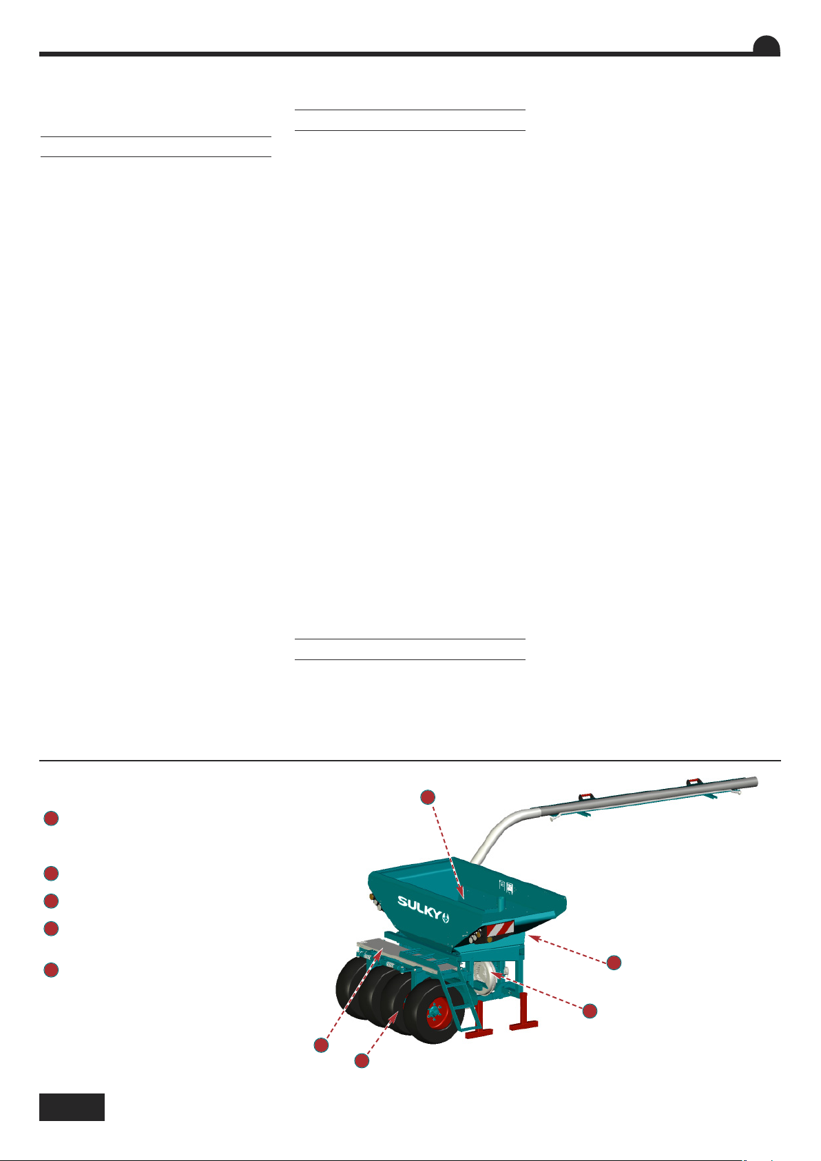
DANGER
1
Rotating shaft
Agitator in the hopper
Universal drive joint
2
Rotating turbine
3
The triangular hitch represents a
crushing hazard
4
Do not remain on the walkway
5
Moving parts
6
1
3
2
4
5
Page 9

ALLGEMEINE SICHERHEITSVORSCHRIFTEN
ALLGEMEINES
BESTIMMUNGSGEMÄSSE VERWENDUNG
DER MASCHINE
ANHÄNGUNG
Sicherheitsvorschriften
DE
Achtung
Nutzlast niemals über-
Bewegliche Maschinen-
Gefahr
teile - sich erst bei Stills-
tand nähern
In der Anweisung werden diese Zeichen in Verbindung mit Empfehlungen für Ihre Sicherheit und der anderer sowie die gute Funktion der Ma-
schine verwendet.
Jeder Benutzer dieser Maschine muß diese Vorschriften genau kennen.
Vor jeder Benutzung und Inbetriebsetzung der
Schlepper-Maschine-Einheit kontrollieren, ob sie
den Sicherheitsvorschriften und den Vorschriften
der Straßenverkehrsordnung entsprechen.
1 - Zusätzlich zu den in diesem Handbuch enthaltenen Anweisungen die Gesetzgebung bezüglich
der Sicherheits- und Unfallverhütungvorschriften
einhalten.
2 - Die auf der Maschine angebrachten Warnungen informieren über die einzuhaltenden Sicherheitsmaßnahmen und tragen zur Unfallverhütung
bei.
3 - Im Straßenverkehr die Straßenverkehrsordnung
einhalten.
4 - Vor Arbeitsbeginn muß sich der Benutzer unbedingt mit den Antriebs- und Bedienungsorganen
der Maschine und ihren jeweiligen Funktionen vertraut machen. Während der Arbeit ist es dafür zu
spät.
5 - Weite Kleidungsstücke, die in sich bewegende
Teile geraten könnten, vermeiden.
6 - Es empfiehlt sich, gemäß den gültigen Normen
einen Schlepper mit Kabine oder Sicherheitsverstärkung zu verwenden.
7 - Vor Inbetriebsetzung und Arbeitsbeginn die direkte Umgebung kontrollieren (Kind!). Für ausreichende Sicht sorgen! Personen oder Tiere aus dem
Maschinengefahrenbereich entfernen (Schutzvorrichtungen!).
8 - Der Transport von Personen oder Tieren auf der
Maschine ist während der Arbeit oder beim Fahren
streng verboten.
9 - Die Maschine darf gemäß den geltenden Sicherheitsnormen nur an den dafür vorgesehenen
Kupplungspunkten angehängt werden.
10 - Besondere Vorsicht ist beim An- und Abbau
der Maschine am Schlepper geboten.
11 - Vor Anhängen der Maschine kontrollieren, ob
der Ballast des Schleppers genügt. Die Ballastelemente müssen gemäß den Vorschriften des
Schlepperherstellers auf den dafür vorgesehenen
Haltern angebracht werden.
12 - Die maximale Achslast und das zulässige Gesamtgewicht einhalten.
13 - Das für den Straßenverkehr maximal zulässige Außenmaß einhalten.
14 - Vor Straßenbenutzung die Schutzvorrichtungen und Signalisierungsvorrichtungen (Licht- und
Rückstrahlelemente) anbringen und ihre Funktion
prüfen. Die defekten Glühbirnen durch Modelle
identischer Art und Farbe ersetzen.
schreiten
15 - Alle Fernsteuerungen (Seil, Kabel, Stange,
Schlauch) müssen so positioniert sein, daß sie
nicht ungewollt betätigt werden und dadurch Unfälle oder Schäden hervorrufen können.
16 - Vor Benutzung der Straße die Maschine
gemäß Herstelleranweisungen in Transportstellung
bringen.
17 -. Fahrersitz nie bei laufender Maschine verlassen.
18 - Fahrgeschwindigkeit und -weise müssen
immer dem Gelände, den Straßen und Wegen angepaßt sein. Auf alle Fälle plötzliche Richtungsänderungen vermeiden.
19 - Die Präzision der Lenkung, die Bodenhaftung
des Schleppers, die Straßenlage und die Wirksamkeit der Bremsvorrichtungen werden beeinflußt
von Faktoren wie: Gewicht und Art der angebauten
Maschine, Belastung der Vorderachse, Zustand des
Geländes oder der Fahrbahn. Die den Bedingungen
entsprechenden Vorsichtsmaßnahmen einhalten.
20 - Besondere Vorsicht ist in Kurven geboten.
Schwerpunktlage, Länge, Höhe und Gewicht der
Maschine oder des Anhängers berücksichtigen.
21 - Vor jeder Benutzung der Maschine kontrollieren, ob alle Schutzvorrichtungen angebracht und in
gutem Zustand sind. Bei Beschädigung sofort austauschen.
22 - Vor jeder Benutzung kontrollieren, ob alle
Schrauben und Muttern fest angezogen sind, insbesondere die, mit denen die Geräte befestigt sind
(Scheiben, Paletten, Schirme...). Notfalls anziehen.
23 - Sich nicht im Manövrierbereich der Maschine
aufhalten.
24 - Vorsicht! Auf den Fernsteuerungsorganen,
insbesondere auf denen mit hydraulischem Regelkreis, kann es Stauch- und Abscherzonen geben.
25 - Vor Verlassen des Schleppers oder vor jedem
Eingriff auf der Maschine Motor abschalten, Zündschlüssel abziehen und völligen Stillstand aller bewegten Teile abwarten.
26 - Sich nicht zwischen Schlepper und Maschine
aufhalten, ohne zuvor die Parkbremse angezogen
und/oder Keile unter die Räder gelegt zu haben.
27 - Vor jedem Eingriff an der Maschine kontrollieren, ob diese nicht ungewollt in Betrieb gesetzt
werden kann.
28 - Die Aufhängöse nicht zum Heben der gefüllten Maschine benutzen.
Die Drillmaschine darf nur für die Arbeiten eingesetzt werden, für die er geplant ist.
Bei Beschädigung der Maschine infolge einer nicht
vom Hersteller spezifizierten Benutzung ist dieser
nicht haftbar.
Gefahr der
Beschädigung
der Maschine
Verletzungsgefahr Hinweis zur
Erleichterung
der Arbeit
Jede nicht der ursprünglichen Bestimmung der
Maschine entsprechende Benutzung erfolgt auf
Rechnung und Gefahr des Benutzers.
Die bestimmungsgemäße Verwendung der Maschine setzt ebenfalls voraus:
- die Einhaltung der vom Hersteller verordneten
Benutzungs-, Wartungs- und Instandsetzungsvorschriften,
- die ausschließliche Verwendung von Originalersatzteilen, Originalausrüstungen und Originalzubehör oder von Teilen, die vom Hersteller empfohlen
sind.
Die Drillmaschine darf nur von kompetenten, mit
den technischen Daten und Benutzungsanweisungen der Maschine vertrauten Personen benutzt,
gewartet und repariert werden, die über die Risiken
informiert sind, denen sie ausgesetzt sein könnten.
Streng die gültige Reglementierung einhalten bezüglich:
- der Unfallverhütung,
- der Arbeitssicherheit (Arbeitsgesetzbuch)
- des Straßenverkehrs (Straßenverkehrsordnung).
Die auf der Maschine angebrachten Warnungen
berücksichtigen.
Der Hersteller haftet nicht für Schäden, die durch
Abänderungen entstehen, die vom Benutzer selbst
oder von Dritten ohne schriftliche Genehmigung an
der Maschine vorgenommen wurden.
- Der am Fahrersitz bei geschlossener Kabine gemessene Geräuschemissionswert (Schalldruckpegel) beträgt 75 dB(A).
Messgerät: SL 401
Position Mikrofons nach Absatz B.2.6 Anhang B
der Norm EN ISO 4254-1.
Dieser Schalldruckpegel ist im Wesentlichen vom
verwendeten Schleppertyp abhängig.
1 - Beim An- und Abkuppeln der Maschine am
Schlepper, den Steuerhebel des Hydraulikkrafthebers so stellen, daß der Hub-vorgang nicht unerwartet ausgelöst werden kann.
2 - Beim Anhängen der Maschine am Dreipunktkraftheber des Schleppers darauf achten, daß die
Spindel- oder Zapfendurchmesser dem Durchmesser der Schlepperkugelgelenke entsprechen.
3 - Vorsicht! Im Dreipunkt-Hubbereich bestehen
Stauch- und Abscherrisiken!
4 - Sich bei Betätigung des äußeren KraftheberSteuerhebels nicht zwischen Schlepper und Maschine aufhalten.
5 - Beim Transport muß die Maschine durch die
Versteifungsstreben des Krafthebers zur Vermeidung von Unwucht und seitlicher Pendelung stabilisiert werden.
Beschädigungsgefahr
Siehe Betriebsanleitung der Ma-
schine
7
Page 10
ANTRIEBSORGANE
HYDRAULIKLEITUNG
WARTUNG
DE
6 - Beim Transport der Maschine in angehobener
Stellung den Kraftheber-Steuerhebel blockieren.
7 - Maschine niemals bei gefülltem Tank abkuppeln.
(Zapfwelle und Gelenkwellen-Antrieb)
1 - Nur die mit der Maschine gelieferte oder vom
Konstrukteur empfohlene Gelenkwelle verwenden.
2 - Die Schutzvorrichtungen der Zapfwellen und
Gelenkwellen müssen immer angebracht und in
gutem Zustand sein.
3 - Auf die richtige Überlappung der Gelenkwellenrohre sowohl in Arbeits- als auch in Transportstellung achten.
4 - Vor Anschließen oder Abziehen einer Gelenkwelle die Zapfwelle auskuppeln, den Motor abschalten und den Zündschlüssel abziehen.
5 - Ist die Primärkardanwelle mit einem Drehmomentbegrenzer oder einer Freilaufkupplung ausgestattet, müssen diese unbedingt auf der
Zapfwelle der Maschine montiert sein.
6 - Immer auf die korrekte Montage und Verriegelung der Kardanantriebe achten.
7 - Immer darauf achten, daß die Schutzvorrichtungen der Gelenkwellen mit den dafür vorgesehenen Ketten gegen Verdrehen gesichert sind.
8 - Vor Kuppeln der Zapfwelle prüfen, ob die gewählte Drehzahl und die Drehrichtung der Zapfwelle den Vorschriften des Herstellers entsprechen.
9 - Vor Kuppeln der Zapfwelle kontrollieren, ob
sich keine Personen oder Tiere in Nähe der Maschine befinden.
10 - Die Zapfwelle auskuppeln, wenn Gefahr besteht, daß die vom Hersteller vorgeschriebenen
Grenzen des Gelenkwellenwinkels überschritten
werden.
11 - Vorsicht! Nach Auskuppeln der Zapfwelle
können Teile der Maschine noch einige Zeit nachlaufen. Sich ihnen nie vor völligem Stillstand nähern.
12 - Bei Abbau der Maschine die Gelenkwellen
auf den dafür vorgesehenen Haltern ablegen.
13 - Nach Abziehen der Gelenkwelle von der
Schlepperzapfwelle muß diese mit ihrer Schutzkappe bedeckt werden.
14 - Schadhafte Schutzvorrichtungen der Zapf-
welle und der Gelenkwellemüssen sofort ausgewechselt werden.
1 - Vorsicht! Die Hydraulikleitung steht unter
Druck.
2 - Bei Montage von Zylindern oder Hydraulikmotoren auf den korrekten Anschluß gemäß Anweisungen des Herstellers achten.
3 - Vor Anschluß eines Schlauches an der Hydraulikleitung des Schleppers dafür sorgen, daß die
schlepper- und maschinenseitigen Leitungen nicht
unter Druck stehen.
4 - Dem Benutzer der Maschine wird zur Vermeidung falscher Anschlüsse dringend geraten, die
Kennzeichnungen auf den Hydraulikanschlüssen
zwischen Schlepper und Maschine zu beachten, da
sonst die Gefahr einer Funktionsumkehrung besteht. (z.B.: Heben/Senken).
5 - Einmal im Jahr die Hydraulikschläuche kontrollieren auf:
. Beschädigung der Außenschicht
. Porosität der Außenschicht
. Verformung ohne Druck und unter Druck
. Zustand der Verbindungen und Dichtungen.
Die maximale Benutzungsdauer der Schläuche ist
6 Jahre. Beim Auswechseln darauf achten, daß nur
Schläuche verwendet werden, deren Eigenschaften
und Qualität den Vorschriften des Maschinenkonstrukteurs entsprechen.
6 - Bei Feststellung einer undichten Stelle alle Vorsichtsmaßnahmen zur Unfallverhütung treffen.
7 - Eine unter Druck stehende Flüssigkeit, insbesondere das Öl der Hydraulikleitung, kann die Haut
durchdringen und schwere Verletzungen verursachen! Bei Verletzungen sofort Arzt Konsultieren;
Infektionsgefahr!
8 - Vor jedem Eingriff in die Hydraulikanlage Maschine ablassen, Anlage drucklos schalten, Motor
abstellen und Zündschlüssel abziehen.
1 - Vor Instandsetzungs-, Wartungs- oder Reparaturarbeiten sowie bei Ermitteln einer Pannen- oder
Betriebsstörungsquelle muß die Zapfwelle ausge-
kuppelt, der Motor abgeschaltet und der Zündschlüssel abgezogen sein.
2 - Regelmäßig kontrollieren, ob Schrauben und
Muttern fest angezogen sind. Notfalls anziehen.
3 - Vor Wartung einer Maschine in angehobener
Stellung diese mit einem geeigneten Mittel abstützen.
4 - Beim Austausch eines Funktionsteiles (Schaufel bei Streuern oder Schare bei Drillmaschinen)
Schutzhandschuhe tragen und nur geeignete Werkzeuge benutzen.
5 - Zum Schutz der Umwelt ist es verboten, Öl,
Fett und Filter jeder Art wegzuwerfen oder auszugießen. Sie sind von darauf spezialisierten Unternehmen zu entsorgen.
6 - Vor Eingriff an der elektrischen Leitung die
Stromzufuhr unterbrechen.
7 - Verschleiß ausgesetzte Schutzvorrichtungen
müssen regelmäßig kontrolliert werden. Sie sofort
austauschen, wenn schadhaft.
8 - Ersatzteile müssen den vom Konstrukteur festgelegten Normen und Kennwerten entsprechen.
Nur Sulky-Ersatzteile verwenden!
9 - Vor Elektroschweißarbeiten am Schlepper oder
der angehängten Maschine die Kabel des Wechselstromgenerators und der Batterie abziehen.
10 - Reparaturen an Organen, die unter Spannung
oder Druck stehen (Federn, Druckspeicher, usw...)
setzen eine ausreichende Qualifikation voraus und
erfordern Werkzeuge; sie dürfen daher nur von
qualifiziertem Personal durchgeführt werden.
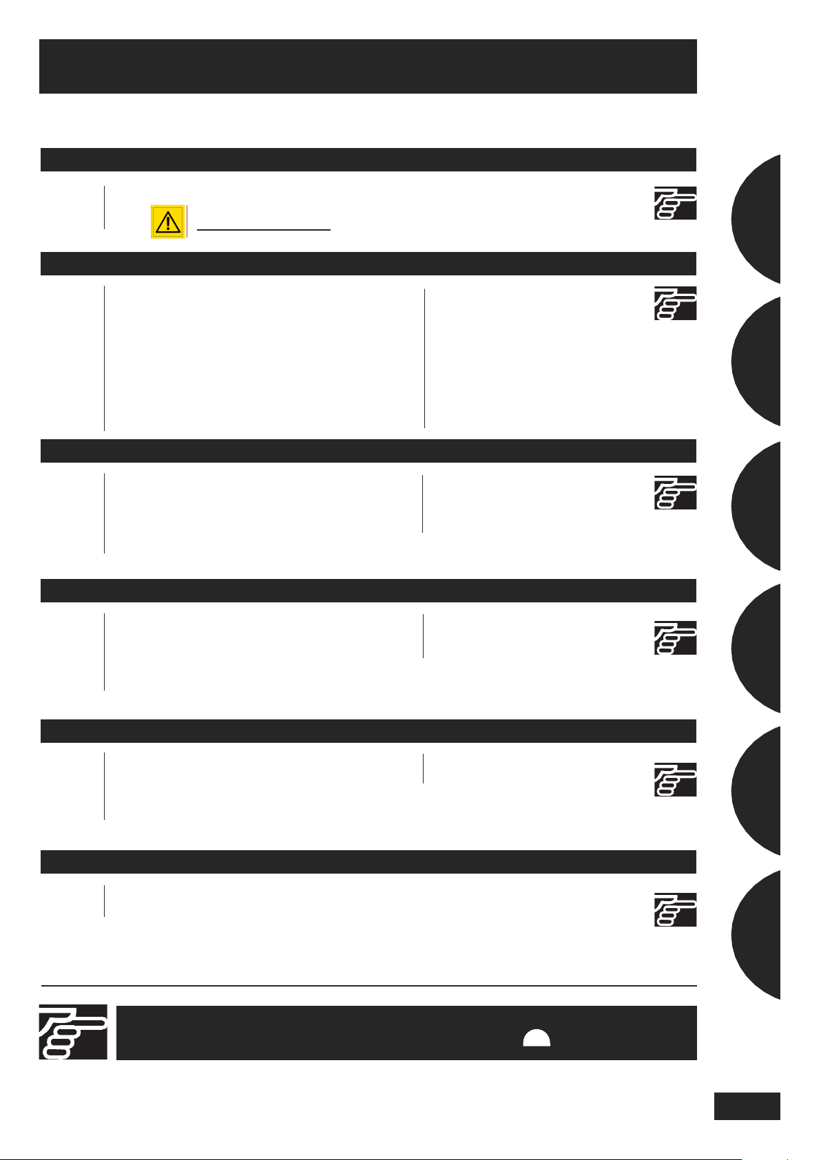
GEFAHR
1
Sich drehende Welle
Trichterrührwerk
Gelenkwelle
2
Sich drehende Turbine
3
Stauchgefahr Dreipunktanbau
4
Kein Fahrzeug auf dem
Ladelaufsteg abstellen
5
Bewegende Teile
8
1
3
2
4
5
Page 11
SOMMAIRE
Français
Pages
AVANT LA MISE EN ROUTE
12 • A Préconisation d’utilisation
A
LIRE
ABSOLUMENT
LIRE
ABSOLUMENT
Pages
15
14-15
14-15
14-15
16-17
16-17
18-21
Pages
46-51
52-53
54-55
56-57
A
MISE EN ROUTE
• A Préparation de la machine
• B Manutention de la trémie
• C Manutention de la rampe de
semis rigide
• D
• E Passage des tuyaux XEOS TF
• F
• G Attelage dételage de la rampe de
Manutention de la rampe de
semis repliable
Tuyau latéral
semis à la herse rotative Cultiline
REGLAGES
• A Réglage du débit
• B Traceurs
• C Réglage de terrage des
rampes repliables
• D Réglage de terrage des
rampes rigides
22-25
26-27
28-29
30-31
36-39
40-41
40-41
42-43
44-45
58-59
60-63
64-65
• H Branchement hydraulique
• I Branchement électrique
• J Turbine
• K Contrôle tracteur
• L Déplacement routier
• M Travail du sol sans semis
• N Manœuvre en bout de champ
• O Passerelle de chargement
• P Remplissage de la trémie
• E Réglage de la herse
• F Jalonnage
• G Utilisation de la trémie
frontale avec de l’engrais
1
1
1
2
1
3
Pages
66-67
66-67
68-69
68-69
70-71
Pages
76-77
78-79
80-81
82-83
Pages
88-89 • A Tableaux de réglage
ENTRETIEN
• A Nettoyage
• B Graissage
• C Vérification
• D Distribution monodoseur
• E Caractéristiques techniques
EQUIPEMENTS
• A Limiteur de profondeur
• B Compteur d'hectares
• C Roues de réappui
• D Utilisation du sélecteur
hydraulique
TABLEAUX DE REGLAGE
72-73
72-73
74-75
84-85
86-87
• F Positions Autocollants
• G Remisage
• H Vidange de la trémie
• E Utilisation du tasse avant
• F Kit de semis vert
1
4
1
5
1
6
Lire attentivement la notice avant l’utilisation. Comprendre son semoir
c’est mieux l’utiliser. En français suivre le symbole.
FR
9
Page 12
English
CONTENTS
Pages
BEFORE START-UP
13 • A Recommendations for use
READING
READING
Pages
15
14-15
14-15
14-15
16-17
16-17
18-21
Pages
46-51
52-53
54-55
56-57
REQUIRED
REQUIRED
START-UP
• A Preparing the machine
• B Handling the seed box
• C Handling the rigid coulter bar
• D Handling the folding coulter bar
• E Alignment of the XEOS TF
pipes
• F Side pipe
• G Hitching and unhitching the
coulter bar and Cultiline
power harrow
SETTINGS
• A Setting the flow
• B Markers
• C Folding bar depth setting
• D Rigid bar depth setting
22-25
26-27
28-29
32-33
36-39
40-41
40-41
42-43
44-45
58-59
60-63
64-65
• H Hydraulic connection
• I Electrical connection
• J Fan
• K Tractor control
• L Road travel
• M Cultivating without drilling
• N End-of-field manoeuvres
• O Loading platform
• P Filling the hopper
• E Adjusting the harrow
• F Tramlining
• G Using the front hopper with
fertilizer
Pages
66-67
66-67
68-69
68-69
70-71
Pages
76-77
78-79
80-81
82-83
Pages
88-89 • A Seeding charts
MAINTENANCE
• A Cleaning
• B Greasing
• C Check
• D Metering device
• E Technical specifications
ACCESSORIES
• A Depth limiter
• B Areameter
• C Packer wheels
• D Using the hydraulic selector
SETTING CHARTS
72-73
72-73
74-75
84-85
86-87
• F Sticker positions
• G Storage
• H Emptying the hopper
• E Using the front packer
• F Green drilling kit
10
Read the manual carefully before use. Better understanding
means better and safer sowing. For English follow the symbol.
GB
Page 13

VERZEICHNIS
Deutsch
Seite
VORBEMERKUNGEN
13 • A Bedienungsempfehlungen
LESEN
LESEN
Seite
15
14-15
14-15
14-15
16-17
16-17
18-21
Seite
46-51
52-53
54-55
56-57
SORGFÄLTIG
SORGFÄLTIG
INBETRIEBSETZUNG
• A Vorbereitung der Maschine
• B Handhabung des Tanks
• C Handhabung des festen
Saatgestänges
• D Handhabung des klappbaren
Saatgestänges
• E Leitungsführung XEOS TF
• F Seitlicher Gebläseschlauch
• G An- und Abkuppeln des
Saatgestänges an die Kreise-
EINSTELLUNGEN
• A Einstellung der Saatmenge
• B Spurreißer
• C Einstellung der Ablagetiefe
bei klappbarem Saatgestänge
• D Einstellung der Ablagetiefe
bei festem Saatgestänge
22-25
26-27
28-29
34-35
36-39
40-41
40-41
42-43
44-45
58-59
60-63
64-65
legge Cultiline
• H Hydraulischer Anschluss
• I Elektrischer Anschluß
• J Turbine
• K Schleppersteuerung
• L
• M Bodenbearbeitung ohne Aussaat
• N Manövrieren am Feldende
• O Ladelaufsteg
• P Füllen des tanks
• E Einstellung der Egge
• F Fahrgassenmarkierung
• G Verwendung des Fronttanks
Straßentransport
mit Dünger
1
1
1
2
1
3
Seite
66-67
66-67
68-69
68-69
70-71
Seite
76-77
78-79
80-81
82-83
Seite
88-89 • A Einstelltabellen
WARTUNG
• A Reinigung
• B Schmierung
• C Kontrolle
• D Saatgutverteilung
Monodosierer
• E Technische Daten
AUSRÜSTUNGEN
• A Sätiefenbegrenzer
• B Hektarzähler
• C Saatandrückräder
• D Verwendung des
Hydraulikwählschalters
EINSTELLTABELLEN
72-73
72-73
74-75
84-85
86-87
• F Sicherheitsaufkleber
• G Abstellen
• H Leeren des Tanks
• E Verwendung
der Frontandruckreifen
• F Aussaatsatz, grün
1
4
1
5
1
6
Anweisung vor Benutzung sorgfältig durchlesen. Die Drillmaschine
verstehen, heißt sie besser benutzen. Die deutsche Fassung ist mit
gekennzeichnet.
DE
11
Page 14
Avant la mise en route
Préconisation d’utilisation
A
FR
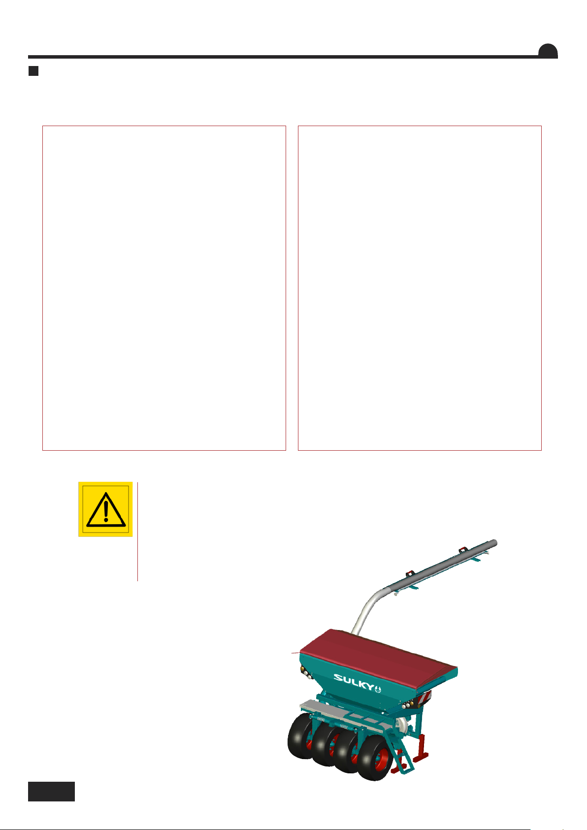
Le semoir XEOS TF est conçu et construit pour semer
toutes les semences courantes dans des situations
très différentes.
Toutefois, il est indispensable de respecter les
recommandations du constructeur et de travailler avec
prudence et bon sens.
Il doit être utilisé exclusivement par du personnel
qualifié et formé.
Lors de son utilisation, il est possible de rencontrer
des situations où les sols sont trop humides ou au
contraire trop secs pour pouvoir faire fonctionner
correctement votre semoir.
Certaines de ces situations difficiles peuvent conduire
à des dommages pour votre semoir ainsi qu’à votre sol.
Sulky ne peut pas être tenu pour responsable des
dommages occasionnés lors d’une utilisation
inappropriée.
Toute modification de la machine opérée sans l’accord
de Sulky annule automatiquement toute garantie du
constructeur.
Les semis sur préparations simplifiées doivent être
pratiqués sur un sol nivelé et fermement rappuyé avec
des résidus de récolte correctement répartis au
préalable.
La présence de cailloux, rochers, souches ou autres
obstacles doit absolument être prise en compte et la
conduite du semoir doit être adaptée.
La vitesse d’utilisation ne doit pas excéder 12 km/h en
semis.
Cependant, il est obligatoire d’adapter sa vitesse en
fonction de l’outil de travail du sol, dans ce cas
consulter la notice d’utilisation de l’outil de travail du
sol.
La vitesse la moins élevée servira alors de référence.
Des variations dans les résultats des semis et leurs
levées ne peuvent être totalement exclues malgré le
soin apporté par Sulky dans la conception et la
fabrication de ce semoir, même lors d’une utilisation
conforme.
Les facteurs pouvant intervenir dans le succès des
semis sont :
- Qualité des semences (enrobages, traitements, densité, vigueur, taux de germinabilité etc.)
- Problème de structure ou d’hétérogénéité des sols,
présence de ravageurs (limaces, mulots).
Lors des semis, il est absolument nécessaire de relever la
machine pour faire un demi-tour dans le champ.
Il n’est pas souhaitable de décrire des courbes trop
prononcées en semant.
La responsabilité de Sulky est totalement dégagée en cas
d’accident survenant lors d’une utilisation de la machine
non-conforme aux prescriptions.
12
Page 15
Before start-up
Recommendations for use
A
GB
The XEOS TF seed drill has been designed and
constructed for drilling all kinds of commonly used
seeds in a variety of different situations.
Nevertheless, it is essential to follow the manufacturer’s recommendations and to work carefully and sensibly.
It must be used only by skilled and trained operators.
It is possible that there will be occasions where the
ground is either too wet or too dry to use the drill properly.
In some of these difficult conditions, using your drill
may result in damage to the machinery or to the soil.
Sulky cannot be held responsible for damage caused by
improper use of the machine.
Any modification to the machine carried out without
Sulky’s approval will automatically invalidate the manufacturer’s guarantee.
Minimum tillage drilling must be carried out on level,
firmly consolidated ground where the harvest residues
have been properly incorporated beforehand.
When drilling, it is absolutely essential to lift the machine up when turning in the field. It is not advisable to turn too tightly when drilling.
The presence of stones, rocks, stumps or other obstacles must be taken into account. The drill must be driven appropriately.
The operating speed for drilling must not exceed 12
km/h.
However, it’s compulsory to adapt the speed according to the soil cultivation tool, in this case, check in
the user book and the lowest speed will be the reference.
Variations in the results of drilling and plant emergence
cannot be completely excluded in spite of the care
taken by Sulky in the design and manufacture of this
seed drill, even when it is used in full compliance with
the instructions.
The factors that may have an impact on the success of
drilling are:
- Seed quality (coatings, treatments, density, vigour,
germination rate, etc.)
- Problems with the structure or heterogeneity of the
soil, presence of pests (slugs, field mice).
1
1
Sulky cannot be held liable in any way in the event of an accident arising due to the use of the
machine that does not comply with the instructions.
Vorbemerkungen
Bedienungsempfehlungen
A
Die XEOS TF Drillmaschine ist darauf ausgelegt, alle
gängigen Saatarten unter sehr verschiedenen Voraussetzungen säen zu können.
Dazu ist es jedoch erforderlich, die Herstellerempfehlungen zu beachten und mit Vorsicht und Vernunft
vorzugehen.
Die Drillmaschine darf nur von qualifiziertem Personal
bedient werden.
Beim Säen können zu feuchte bzw. zu trockene Bodenverhältnisse auftreten, unter denen die Drillmaschine nicht korrekt funktionieren kann.
Einige dieser heiklen Situationen können zu Beschädigungen an der Drillmaschine oder am
Boden führen.
Sulky kann nicht haftbar gemacht werden für Schäden, die aufgrund unsachgemäßer Bedienung oder
Handhabung entstehen.
Werden an der Maschine ohne Zustimmung von Sulky
Änderungen vorgenommen, ist die Herstellergewährleistung ungültig.
Die Aussaat bei vereinfachter Bodenvorbereitung
muss auf planiertem und gut angedrücktem Boden erfolgen, wobei die verbleibenden Pflanzenreste vorher
gut verteilt werden müssen.
DE
Steine, Felsen, Baumstümpfen oder andere Hindernisse sind unbedingt zu berücksichtigen. Die Führung
der Drillmaschine ist an diese Hindernisse anzupassen.
Bei Einsaat mit vereinfachter Bodenvorbereitung darf
die Fahrgeschwindigkeit 12 km/h nicht überschreiten.
Jedoch muß die Geschwindigkeit entsprechend der
Bodenbearbeitungsgeräte angepaßt werden. Dann
sehen Sie nach der Bedienungsanleitung des Bodenbearbeitungsgerät. Die niedrigste Geschwindigkeit
wird als Maßstab dienen.
Abweichende Ergebnisse bei der Aussaat und beim
Saataufgang können trotz der Sorgfalt bei der Entwicklung dieser Drillmaschine durch Sulky, auch bei sachgemäßer Bedienung und Handhabung, nicht völlig
ausgeschlossen werden.
Die für die Aussaatqualität bei Direkteinsaat und bei
vereinfachter Bodenvorbereitung verantwortlichen
Faktoren sind sehr unterschiedlich:
- Saatqualität (Pillieren, Behandlung, Dichte,
Lebenskraft, Keimfähigkeit in Prozent usw.)
- Problem der Bodenstruktur oder der heterogenen
Beschaffenheit des Bodens, Vorliegen von
Schädlingen (Schnecken, Feldmäuse).
Beim Aussäen muss die Maschine beim Wenden im Feld unbedingt angehoben werden.
Es ist nicht zu empfehlen, beim Säen zu enge Kurven zu fahren.
Die Haftung von Sulky ist ausgeschlossen bei Unfällen, die beim Betrieb der Maschinen
unter Nichtbeachtung dieser Betriebsanleitung entstehen.
13
Page 16
Mise en route / Start-up / Inbetriebsetzung
B
14
Ne lever le semoir
qu’avec la trémie vide.
Assurez-vous qu’il n’y ait
personne autour de la
machine lors de la manipulation.
Do not lift the seed drill
unless the seed box is
empty.
Make sure that there is
no-one around the machine during handling
operations.
Drillmaschine nur bei
leerem Tank anheben.
Sicherstellen, dass sich
keine Fremdkörper im
Tank befinden.
Page 17
Mise en route / Start-up / Inbetriebsetzung
A
Préparation de la machine
-
Au moment de la livraison, vérifier que le semoir
soit complet.
-
Assurez-vous qu'il n'y ait pas de corps étrangers
dans la trémie.
Le XEOS TF ne doit être utilisé que pour les travaux
pour lesquels il a été conçu.
-
Vérifier que la machine n’a subi aucun dommage
en cours de transport.
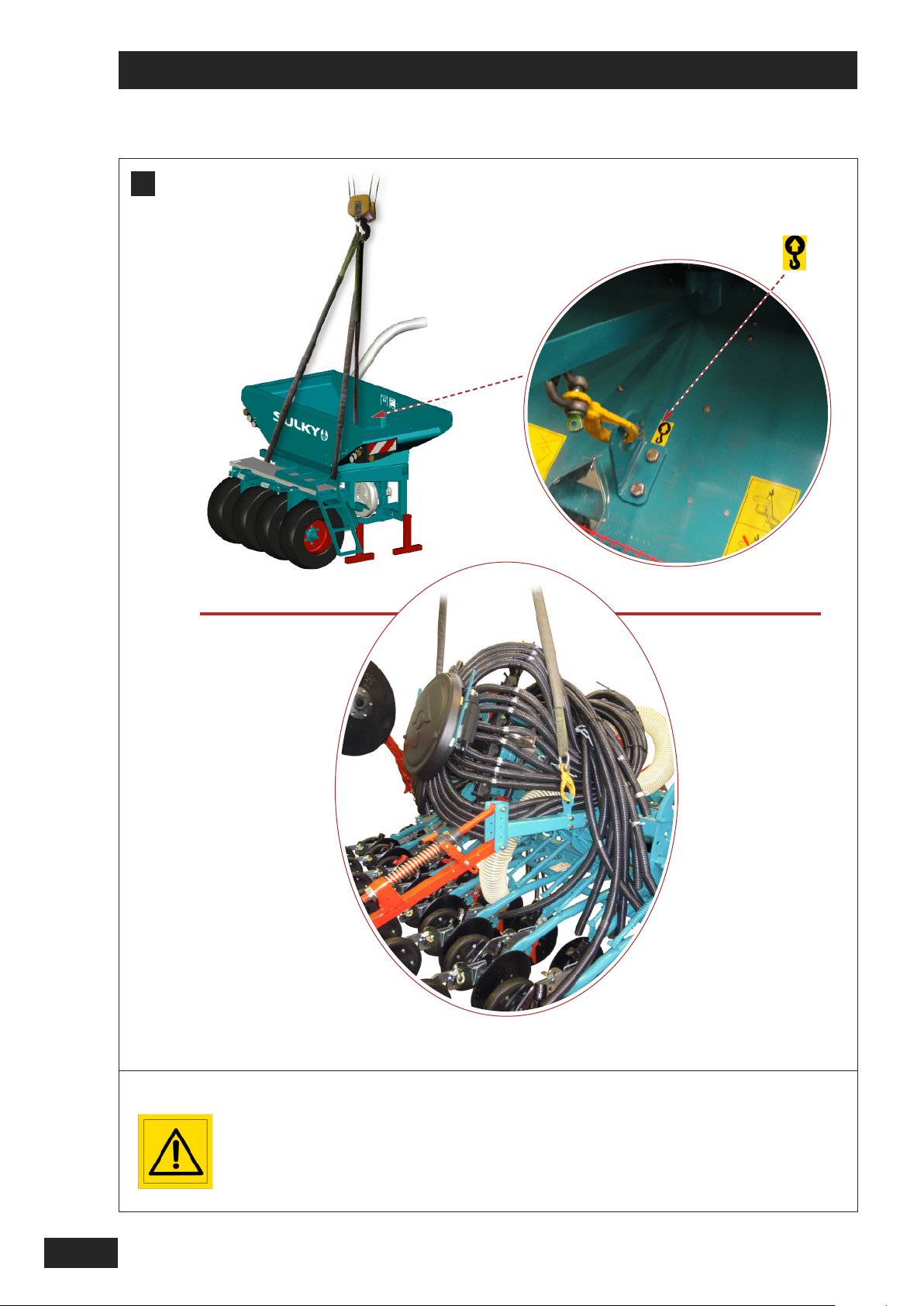
Manutention de la trémie
B
-
Pour manipuler le semoir XEOS TF, utiliser uni-
quement les anneaux soudés prévus à cet effet
C
Manutention de la rampe de semis rigide
-
Pour manipuler la rampe de semis, il est impératif
d’utiliser les anneaux prévus à cet effet.
Veiller à ce que la rampe de semis ne soit
connectée à aucun élément. (câbles,
tuyaux)
FR
1
Seules les réclamations formulées à réception de
la machine pourront être prises en considération.
-
Faire constater d’éventuels dégâts par le
transporteur.
En cas de doute ou de litige, adressez-vous à votre
revendeur.
Preparing the machine
A
A
-
As soon as the drill has been delivered check
that the seed drill is complete.
-
Ensure that there are no foreign bodies in the
seed box.
The XEOS TF should only be used for tasks for which
it has been designed.
- Check that the machine has not suffered any damage during transport.
Only claims made on taking delivery of the
machine will be considered.
-
Any damage should be reported to the delivery
man.
If in doubt or in the event of any complaint, please
contact your dealer.
Manutention de la rampe de semis repliable
D
-
Pour manipuler la rampe de semis, il est impératif
d’utiliser les anneaux prévus à cet effet.
La tête de distribution doit être fixée à la
rampe de semis à l’aide des supports
prévus.
Handling the seed box
B
- Only the welded rings provided should be used to
handle the XEOS TF seed drill.
Handling the rigid coulter bar
C
- To manipulate the coulter bar, use only the
rings provided for this purpose.
Check that the coulter bar is not connected
to any other element. (cables, pipes)
Handling the folding coulter bar
D
- To manipulate the coulter bar, use only the
rings provided for this purpose.
The distribution head must be fixed to the
coulter bar using the supports provided.
2
GB
DE
Vorbereitung der Maschine
A B
A
-
Bei Lieferung prüfen, ob die Drillmaschine komplett
ist.
-
Sicherstellen, dass sich keine Fremdkörper im Tank
befinden.
Die XEOS TF darf nur für die Arbeiten eingesetzt
werden, für die sie bestimmt ist.
- Prüfen, ob die Maschine nicht beim Transport beschädigt wurde.
Nur bei Abnahme der Maschine formulierte
Reklamationen können berücksichtigt werden.
-
Eventuelle Schäden vom Spediteur feststellen
lassen.
Im Zweifels- oder Streitfall Ihren Verkäufer informieren.
Handhabung des Tanks
- Zur Handhabung der Xeos tf Drillmaschine ausschließlich die dazu angeschweißten Ringe benutzen
Handhabung des festen Saatgestänges
C
D
- Zur Handhabung des Saatgestänges ausschließlich die dazu angeschweißten Ringe benutzen.
Darauf achten, dass das Saatgestänge an
keinem Maschinenteil angeschlossen ist
(Kabel, Schläuche)
Handhabung des klappbaren Saatgestänges
- Zur Handhabung des Saatgestänges ausschließlich die dazu angeschweißten Ringe benutzen.
Der Verteilerkopf muss mit Hilfe der vorgesehenen Halter am Saatgestänge befestigt werden.
15
Page 18
Mise en route / Start-up / Inbetriebsetzung
=
=
E
1,5°
=
=
16
Page 19
Mise en route / Start-up / Inbetriebsetzung
E
Passage des tuyaux XEOS TF
Tuyau latéral
F
FR
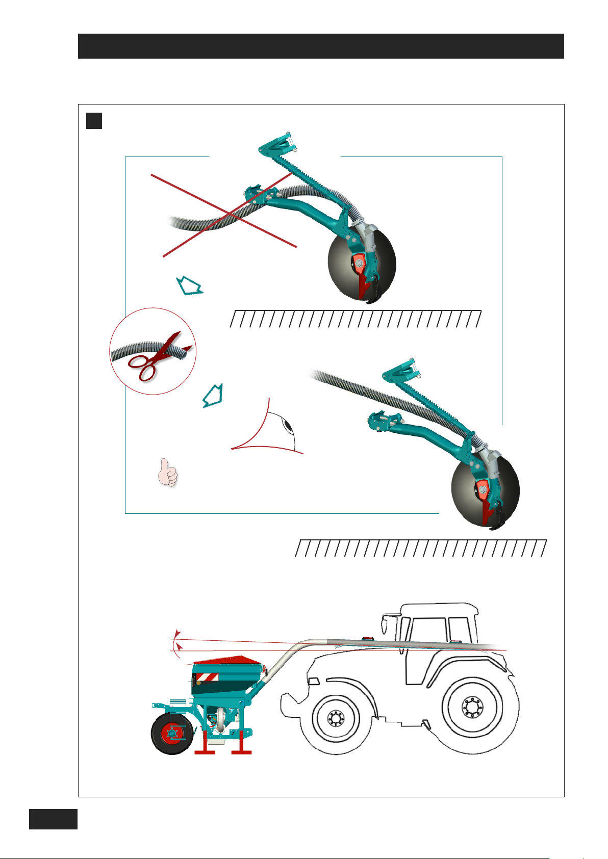
Afin d’éviter tous risques de bouchage, il est important de s’assurer du bon passage des tuyaux.
Lors de la livraison du semoir, effectuer les opérations suivantes :
Ces opérations sont à effectuer semoir relevé !
1- Retirer la butée basse du rouleau Packer.
2- Relever votre ensemble « herse+semoir » afin
qu’il n’y ait plus de contact entre le sol et l’ensemble.
3- S’assurer que les tuyaux aient une pente
régulière.
4- Si nécessaire, recouper les tuyaux.
Alignment of the XEOS TF pipes
E
A
To avoid every risk of blocking, it’s important to be
sure about a good pipe position.
During the drill delivery, follow the instructions bellow:
These operations have to be done drill up!
Il est important de respecter une pente d’au moins
1,5° vers l’arrière.
La fixation du tuyau latéral est à réaliser par votre
concessionnaire.
Il est important que le tuyau soit supporté au moins
par ses deux extrémités.
Side pipe
F
Make sure that there is a slope of at least 1.5° towards the rear.
The side pipe must be fastened by your dealer.
The pipe has to be supported at least by its two
ends.
1
2
GB
1- Remove the lower packer-roller stop.
2- Lift up the drill and power-harrow. It should not
have any contact between the drill and the soil.
3- Be sure that all the pipe have a constant way
down.
4- If necessary, cut the pipe.
Leitungsführung XEOS TF
A
E
Zur Vermeidung jeglicher Verstopfungsgefahr ist es
wichtig, eine korrekte Leitungsführung sicherzustellen.
Bei Lieferung der Drillmaschine sind folgende Arbeitsschritte vorzunehmen:
Diese Vorgänge sind bei angehobener Drillmaschine durchzuführen!
1- Unteren Anschlag der Packerwalze entfernen.
2- Anheben Ihres Gespanns „Egge+Drillmaschine“,
so dass dieses keinen Bodenkontakt mehr zeigt.
3- Sicherstellen, dass die Leitungen eine regelmä-
ßige Neigung aufweisen.
4- Falls notwendig, Leitungen zuschneiden.
Seitlicher Gebläseschlauch
F
Wichtig: bitte beachten Sie eine Neigung von mindestens 1,5° nach hinten.
Der seitliche Gebläseschlauch ist von Ihrem Fachhändler zu befestigen.
Es ist wichtig, dass der Gebläseschlauch mindestens
an beiden Enden gehalten wird.
DE
17
Page 20
Mise en route / Start-up / Inbetriebsetzung
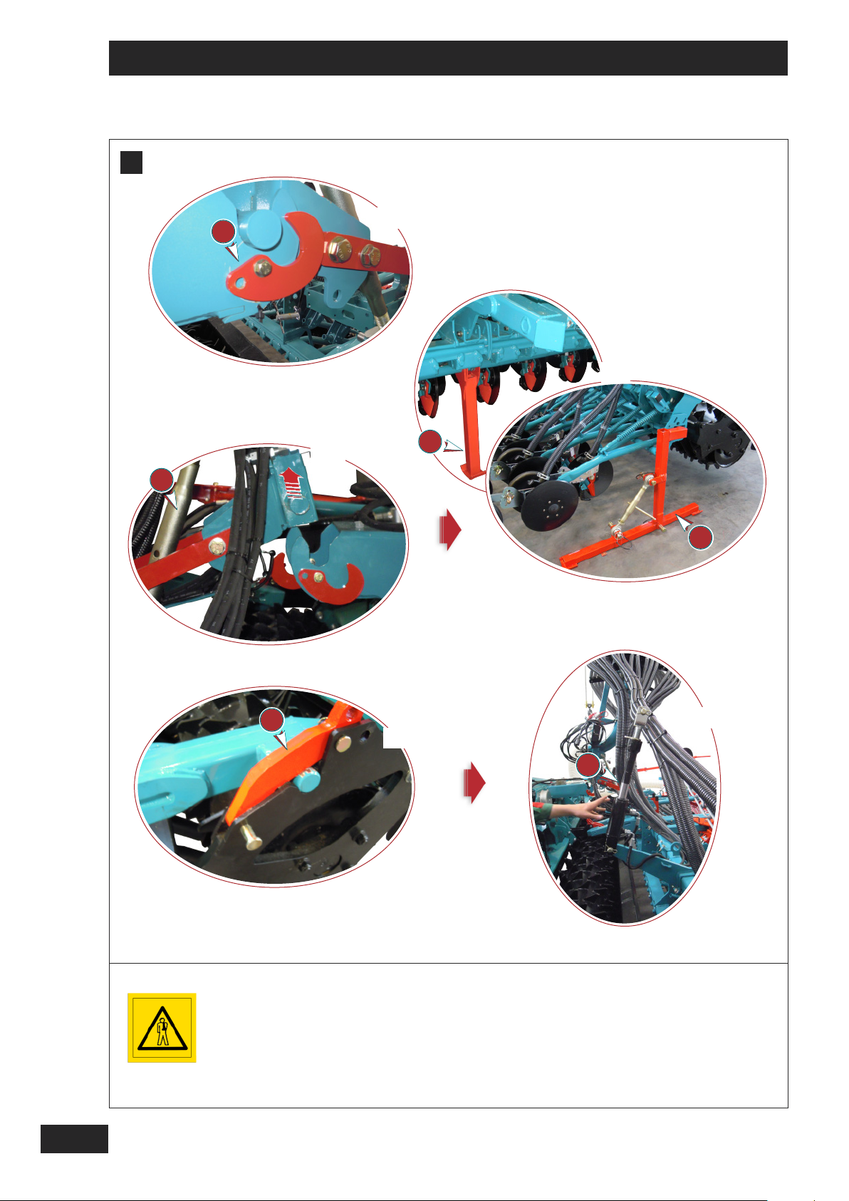
G
I
I
II
II
III
III
1
2
IV
IV
3
3
18
Du bon montage du triangle dépend le bon positionnement du
Semoir/Herse.
Assurez-vous qu'il n'y ait
personne autour de la
machine lors de la manipulation.
Correct seed drill/harrow
positioning depends on
mounting the triangle
correctly.
Make sure that there is
no-one around the machine during handling
operations.
Die gute Positionierung
der Drillmaschine/Egge
hängt von der richtigen
Montage des Dreiecks ab.
Sich vergewissern, daß
sich dabei niemand im
Maschinenbereich aufhält.
Page 21
Mise en route / Start-up / Inbetriebsetzung
G
Attelage dételage de la rampe de semis à la
herse rotative Cultiline
Dételage
FR
Avant toutes choses, il est important de veiller
aux règles de sécurités et de bon sens.
Eloigner les enfants et les personnes n’ayant
pas prit connaissance du manuel d’utilisation.
Cette opération doit être réalisée sur sol
parfaitement plat et le semoir doit être
stable.
Assurez-vous que l’aire soit dégagée et
qu’il n’y ait personne autour de la
machine.
Hitching and unhitching the coulter bar and
G
A
Cultiline power harrow
Unhitching
Most importantly, comply with all safety rules
and use common sense.
Keep children away and anyone who is not
familiar with the operating manual.
This operation should be carried out on perfectly level ground and the seed drill must be
stable.
I
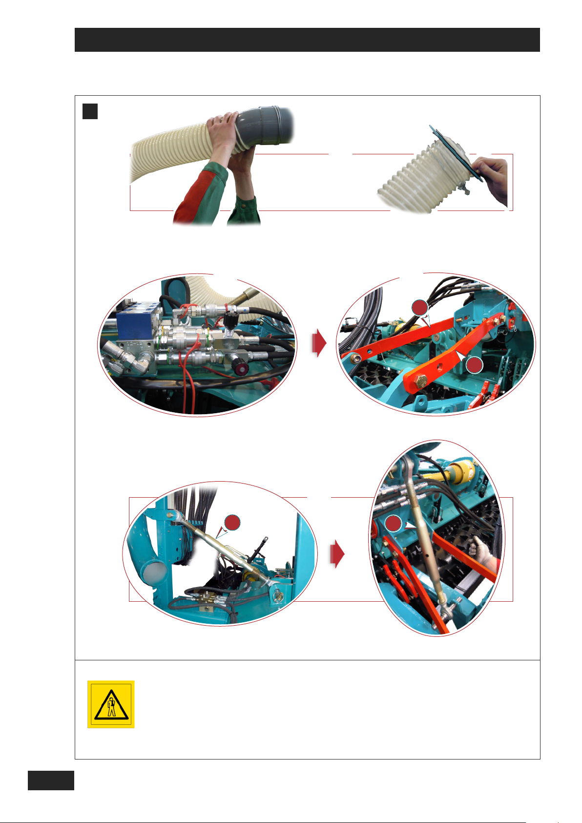
Débrancher le tuyau latéral et le retirer de son
I
support central.
II
Retirer toutes les prises hydrauliques ainsi que
II
les prises électriques.
III
Mettre en place les pièces et .
III
IV
Placer le tirant de la position 1 à la position 2.
IV
I Disconnect the side pipe and remove it from its
I
central support.
II Remove all of the hydraulic and electric
II
connectors.
Fit the parts and .
III
III
IV Move the tie rod from position 1 to
IV
position 2.
3
21
3
21
1
2
GB
Check that the area is clear and no one is
standing next to the machine.
An- und Abkuppeln des Saatgestänges an
A
G
die Kreiselegge Cultiline
Abkuppeln
Zunächst ist es wichtig, die Sicherheitsregeln
zu beachten und mit Vernunft vorzugehen.
Kinder und Personen, die das Handbuch nicht
gelesen haben, aus dem Gefahrenbereich
entfernen.
Der Anbau muss auf vollständig flachem Untergrund erfolgen und die Drillmaschine muss
sich in stabiler Lage befinden.
Sicherstellen, dass genügend Platz vorhanden
ist und sich niemand im Maschinenbereich
befindet.
I Seitlichen Gebläseschlauch abtrennen und von
I
seinem zentralen Halter abnehmen.
II Sämtliche hydraulische und elektrische An-
II
schlüsse unterbrechen.
Teile und in Stellung bringen.
III
III
IV Oberlenker von Position 1 in Position 2 brin-
IV
gen.
21
3
DE
19
Page 22
Mise en route / Start-up / Inbetriebsetzung
G
V
V
4
VII
VII
VI
VI
5
3
5
IX
6
VIII
VIII
IX
7
20
Vérifier que le Xeos soit
bien stable sur ses béquilles.
Bien respecter l'ordre des
opérations.
Assurez-vous qu'il n'y ait
personne autour de la
machine lors de la manipulation.
Check that the Xeos is perfectly stable on its parking
supports.
Carry out the operations
in the correct order.
Make sure that there is
no-one around the machine during handling
operations.
Prüfen, ob der Xeos fest
auf seinen Stützen liegt.
Reihenfolge der Arbeitsgänge einhalten.
Sich vergewissern, daß
sich dabei niemand im
Maschinenbereich aufhält.
Page 23
Mise en route / Start-up / Inbetriebsetzung
G
FR
V
Déverrouiller les crochets .
V
VI
A l’aide du tirant lever la tête afin de la dé-
VI
gager de son support
VII
Placer les béquilles de maintient de la rampe
VII
de semis de part et d’autre du semoir sans oublier la béquille centrale.
Trouver le point neutre sur les tirants mobiles
placés sur les béquilles.
VIII
Déverrouiller les brides de fermeture sur le
VIII
rouleau Packer.
IX
Retirer les vérins (option) ou tirants supé-
IX
rieurs.
G
A
V
Unlock the hooks .
V
VI Use the tie rod to lift the head in order to
VI
release it from its support
VII Fit the parking supports to maintain the
VII
coulter bar on either side of the drill and do not
forget the central support.
3
7
3
4
5
4
5
1
6
GB
2
Find the neutral point on the mobile tie rods
placed on the supports.
VIII Unlock the closing clamps on the Packer
VIII
roller.
IX Remove the cylinders (option) or upper tie
IX
rods.
A
G
V Die Haken entriegeln.
V
VI Verteilerkopf mit Hilfe des Oberlenkers an-
VI
heben, um ihn aus seinem Halter zu heben.
VII Haltestützen des Saatgestänges an beiden
VII
Seiten der Drillmaschine platzieren, ohne die
mittige Stütze zu vergessen.
Neutralen Punkt an den beweglichen Lenkern
der Stützen suchen.
VIII Verschlussflanschen an der Packerwalze
VIII
entriegeln.
4
5
6
7
6
DE
3
IX Auslöser (Option) bzw. obere Lenker ab-
IX
nehmen.
7
21
Page 24
Mise en route / Start-up / Inbetriebsetzung
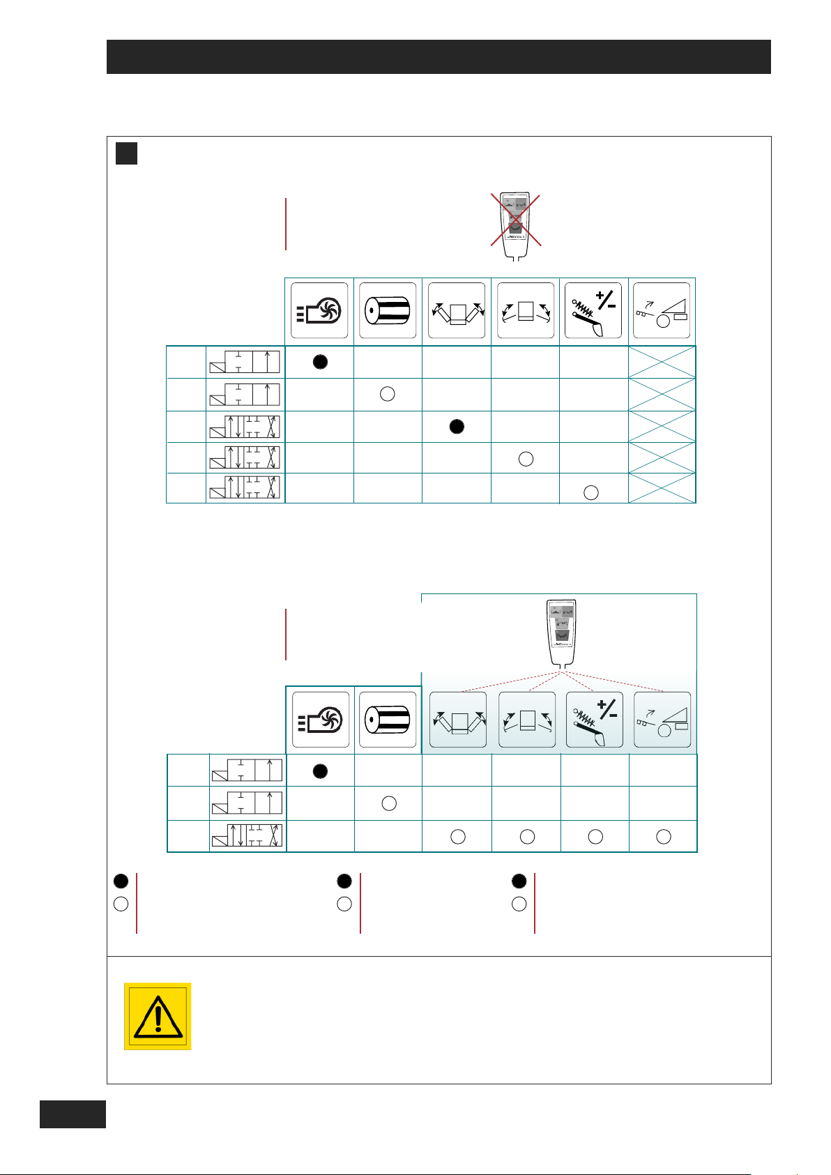
H
MONTAGE SANS SÉLECTEUR
ASSEMBLY WITHOUT SELECTOR
MONTAGE OHNE WÄHLSCHALTER
1 SE
1 SE
1 DE
1 DE
1 DE
1 SE
1 DE
*
MONTAGE AVEC SÉLECTEUR
ASSEMBLY WITH SELECTOR
MONTAGE MIT WÄHLSCHALTER
On / Of
22
1 DE
DE SÉRIE
OPTION
EN REPLIABLE UNIQUEMENT
*
Il est recommandé de
réaliser l’alimentation directement depuis la batterie pour éviter toute
microcoupure.
Veillez à garder propre les
prises hydrauliques Push
Pull.
STANDARD
OPTIONAL
FOLDING ONLY
*
*
We recommend that the
unit is connected directly
to the battery to ensure a
constant power supply.
Make sure that the hydraulic push-pull connector is kept clean.
SERIENMÄSSIG
OPTION
NUR BEI KLAPPBARER AUSFÜHRUNG
Wir empfehlen eine Direktversorgung ab Batterie zur Vermeidung von
Mikroabschaltungen.
Push-Pull-Hydraulikstecker sauber halten.
Page 25

Mise en route / Start-up / Inbetriebsetzung
FR
H
Branchement Hydraulique
T
RÉMIE
- Connecter la turbine à un distributeur simple
effet à retour libre.
Un accouplement femelle 1 pouce est livré avec la
machine pour être installé sur le tracteur directement sur le réservoir.
Si aucun distributeur n'est disponible à l'avant du
tracteur, il faudra en envisager l'installation.
L'activation et la désactivation du semoir se fait à
l'aide d'un distributeur simple effet si vous avez
choisi de l'opérer par hydraulique.
R
AMPE DE SEMIS
Le repliage de l'ensemble arrière (cas ou rampe
de semis repliable) nécessite un distributeur double effet.
Hydraulic Connection
H
A
HOPPER
- Connect the fan to a single-acting spool valve
with free return.
La manipulation des traceurs requière un distributeur double effet.
L'utilisation de la modulation hydraulique de terrage
nécessite un distributeur double effet.
Le relevage hydraulique de la rampe de semis n'est
disponible qu'avec le sélecteur hydraulique (option).
Le sélecteur hydraulique fonctionne avec un distributeur double effet et permet de faire fonctionner le
repliage, les traceurs, la modulation hydraulique de
terrage et enfin le relevage hydraulique de la barre
de semis.
Manipulating markers requires a double-acting spool
valve.
Using hydraulic depth modulation requires a doubleacting spool valve.
1
2
GB
A 1-inch female coupling is supplied with the machine
to be installed on the tractor directly on the reservoir.
If no spool valve is available at the front of the tractor,
you must consider installing one.
Activating and deactivating the drill is done using a single-acting spool valve if you have selected to operate
it with hydraulics.
C
OULTER BAR
Folding the rear unit (case with a folding coulter
bar) requires a single acting spool valve.
Hydraulischer Anschluss
A
H
SAATGUTTANK
- Turbine an ein einfachwirkendes Steuerventil mit
freier Rückleitung anschließen.
Eine 1-Inch Kupplungssteckdose gehört zum Lieferumfang der Maschine, um direkt am Druckbehälter
des Schleppers montiert zu werden.
Ist an der Schlepperfrontseite kein Steuerventil vorhanden, sollte eines eingebaut werden.
Die Aktivierung bzw. Inaktivierung der Drillmaschine
erfolgt mittels eines einfachwirkenden Steuerventils,
wenn eine Hydrauliksteuerung erwünscht ist.
Hydraulic lift for the coulter bar is available only with
the hydraulic selector (optional).
The hydraulic selector operates with a double-acting
spool valve and enables operation of folding, markers,
hydraulic depth modulation and finally hydraulic lifting
for the coulter bar.
DE
Die Handhabung der Spurreißer erfordert ein doppelwirkendes Steuerventil.
Die Modulierung der Ablagetiefe erfolgt über ein doppelwirkendes Steuerventil.
Die Hebehydraulik des Saatgestänges ist nur mit dem
Hydraulikwählschalter (Option) möglich.
Der Hydraulikwählschalter wird mit einem doppelwirkenden Steuerventil betrieben. Mit ihm werden der
Klappmechanismus, die Spurreißer, die Modulierung
der Ablagetiefe und die Hebehydraulik der Aussaatstange betrieben.
S
AATGESTÄNGE
Das Einklappen der hinteren Anlage (bei Klappausführungen) erfordert ein doppelwirkendes Steuerventil.
23
Page 26
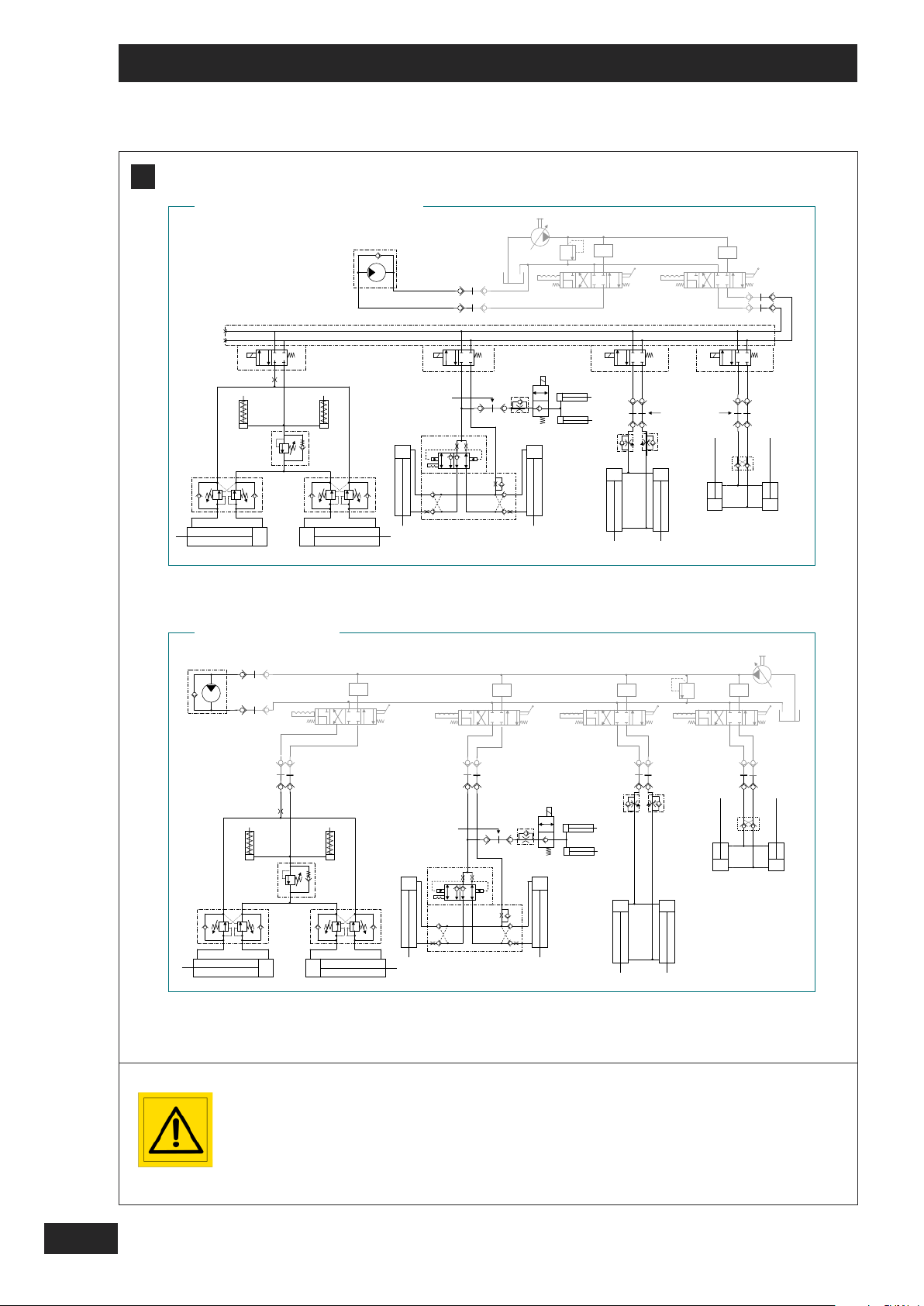
Mise en route / Start-up / Inbetriebsetzung
H
AVEC SELECTEUR DE FONCTION
Gicleur
2mm
DIRECT TRACTEUR
3 2 0 1
repliage
3 2 0 1
<=
F: 50b
<=
F: 50b
P1
2 1
B2
A2
3.5mm
P2
3 mm
B1
A1
3.5mm
3 2 0 1 3 2 0 1 3 2 0 1
3 2 0 1
24
Il est recommandé de
réaliser l’alimentation directement depuis la batterie pour éviter toute
microcoupure.
Veillez à garder propre les
prises hydrauliques Push
Pull.
P1
2 1
B2
A2
P2
3 mm
B1
A1
We recommend that the
unit is connected directly
to the battery to ensure a
constant power supply.
Make sure that the hydraulic push-pull connector is kept clean.
<=
F: 50b
<=
F: 50b
Wir empfehlen eine Direktversorgung ab Batterie zur Vermeidung von
Mikroabschaltungen.
Push-Pull-Hydraulikstecker sauber halten.
Page 27

Mise en route / Start-up / Inbetriebsetzung
H
MONTAGE HYDRAULIQUE TF
VEC SELECTEUR DE FONCTION
1 - A
2 - D
IRECT TRACEUR
FR
1
2
GB
H
A
TF HYDRAULIC ASSEMBLY
1 – W
ITH FUNCTION SELECTOR
2 - DIRECT MARKER
A
H
AUFBAU HYDRAULIKKREIS TF
1 - M
IT FUNKTIONSWÄHLSCHALTER
DE
2 - DIREKT SPURREISSER
25
Page 28
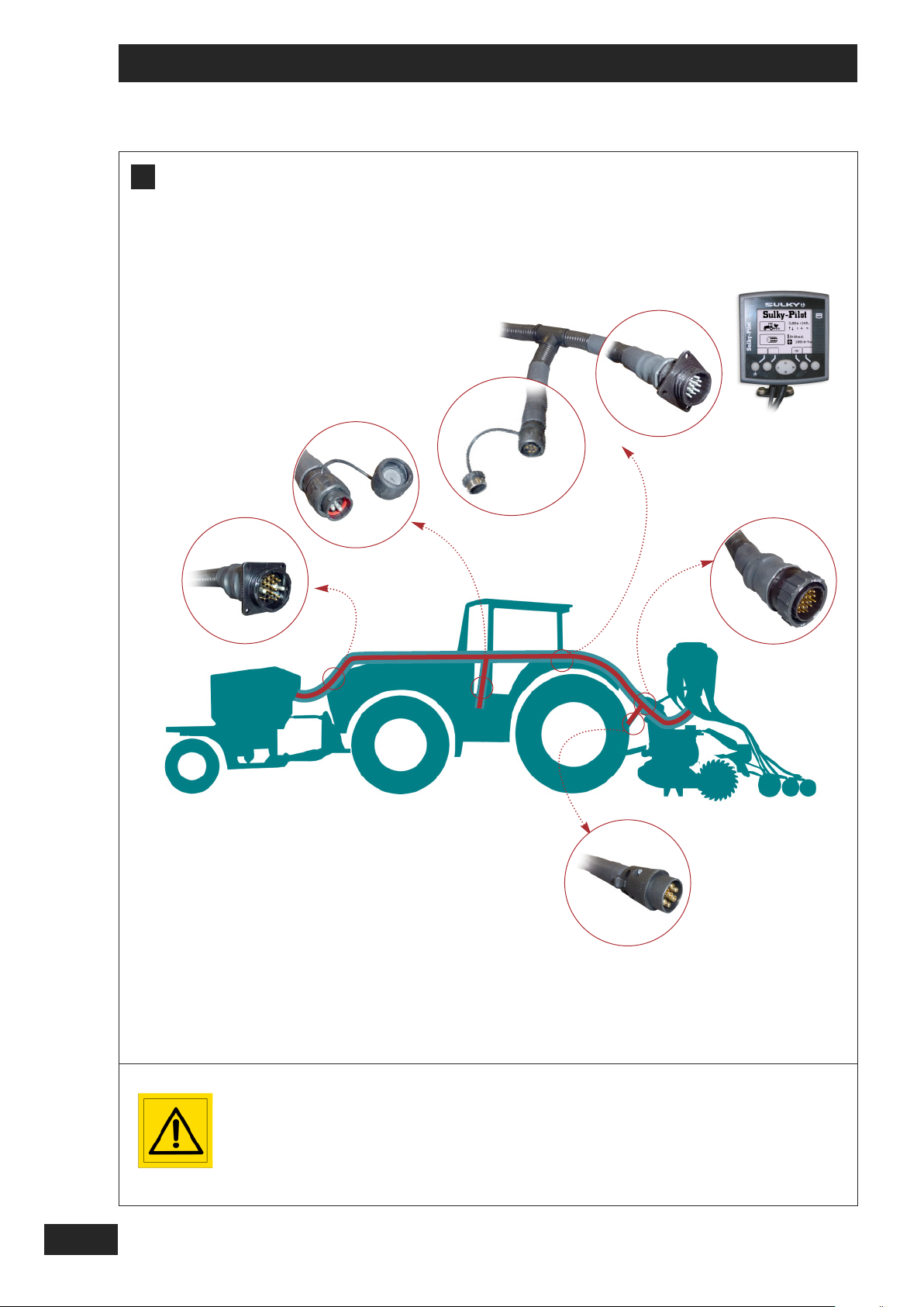
Mise en route / Start-up / Inbetriebsetzung
I
Il est recommandé de
réaliser l’alimentation directement depuis la batterie pour éviter toute
microcoupure.
-
We recommend that the
unit is connected directly
to the battery to ensure a
constant power supply.
+
Wir empfehlen eine Direktversorgung ab Batterie zur Vermeidung von
Mikroabschaltungen.
26
Page 29

Mise en route / Start-up / Inbetriebsetzung
I
Branchement Electrique
Le faisceau électrique de votre combiné de semis avec
trémie frontale intègre toutes les fonctions électriques
de votre machine: Éclairage, puissance, commandes
du boîtier Pilot et fonction électro-hydraulique.
(option)
FR
1
2
GB
Electrical connection
I
A
The electrical bundle for your drill unit with front hopper incorporates all of the electrical functions for your
machine: Lighting, power, Pilot unit controls and the
electrics-hydraulics function. (optional)
Elektrischer Anschluss
A
I
Das Kabelbündel der Drillmaschine mit Fronttank umfasst alle elektrischen Funktionen der Maschine: Beleuchtung, Leistung, Steuerung des
Pilot-Elektronikgeräts und die elektrohydraulische
Steuerung (Option)
DE
27
Page 30

Mise en route / Start-up / Inbetriebsetzung
J
1
28
Il est toujours nécessaire de valider
le régime de turbine lors du début
des travaux au champ.
- Un régime de turbine inapproprié
nuit à la qualité du semis.
- Un régime de turbine insuffisant
provoque des bouchages de
tuyaux.
- Un régime de turbine excessif
éjecte les graines du sillon et ne
permet pas de juger de la pertinence du réglage de profondeur.
Faire les réglages du volet de la turbine tracteur à l'arrêt.
Attention : l’huile peut être sous
pression.
It is always necessary to check the
fan speed when starting work in the
field.
- An inappropriate fan speed is detrimental to drilling quality.
- If the fan speed is too slow, this
can cause blockages in the pipes.
- If the fan speed is too fast, the
grain will be thrown out of the furrow and it will not be possible to
judge whether or not the depth setting is correct.
Carry out adjustments to the fan
flap with the tractor stopped.
Caution: oil may be under pressure!
Vor Beginn der Feldarbeiten ist eine
Bestätigung der Turbinendrehzahl
unerlässlich.
- Eine ungeeignete Turbinendrehzahl beeinträchtigt die Aussaatqualität.
- Eine unzureichende Turbinendrehzahl führt zu Verstopfungen der Leitungen.
- Eine überhöhte Turbinendrehzahl
wirft die Körner aus der Furche und
verhindert die korrekte Bewertung
der Tiefeneinstellung.
Die Einstellungen der Turbinenklappe des Schleppers sind bei Maschinenstillstand vorzunehmen.
Achtung: Das Öl kann unter Druck
stehen.
Page 31

Mise en route / Start-up / Inbetriebsetzung
free return
W
ARNING AND RE MINDER
:
frreeiieerr RRüücckklleeiittuunngg
W
D
E
G
:
retour libre
AVERTISSE MENT ET RAPPEL
FR
Turbine
J
Il est impératif d’utiliser un tracteur avec une pompe à
débit variable “load-sensing” et d’utiliser le régulateur
du tracteur pour régler la vitesse de la turbine.
Le débit d'huile nécessaire pour une vitesse de rotation de la turbine d'environ 4400 tr/mn est de 45 l/mn
aux auxiliaires à une pression de 100 bars.
L'utilisation de la turbine hydraulique nécessite son
branchement sur un distributeur simple effet du tracteur avec un
.
Afin d'éviter toutes perturbations de l'hydraulique, il est
conseillé de brancher la turbine sur le distributeur prioritaire du tracteur.
:
L'utilisation de l'entraînement hydraulique de la turbine
entraîne quelques vérifications sur le tracteur, consulter votre revendeur.
J
A
Fan
A tractor with a “load-sensing” variable flow pump
must be used and the tractor’s regulator must be used
to set the fan speed.
The auxiliary oil flow rate required to achieve a fan rotation speed of approximately 4400 rpm is 45 l / min at
a pressure of 100 bar.
Retour libre impératif. La pression du retour
doit être obligatoirement inférieure à 10 bars,
pour garantir un bon fonctionnement du
moteur hydraulique.
-
Contrôler régulièrement la propreté du tamis
d’aspiration de la turbine , afin de garantir le
1
bon fonctionnement du transport pneumatique.
-
Nettoyer toujours correctement les raccords
hydrauliques.
Lors de la première mise en service, une correction
du nombre de tours est obligatoire entre le démarrage
(huile froide) et le fonctionnement normal (huile
chaude).
Le contrôle de la vitesse de rotation de la turbine se
fait avec le boîtier PILOT.
Branchement au tracteur
- Flexible d’alimentation et de retour avec Push pull.
Free return is essential. The return pressure
must be lower than 10 bar in order for the
hydraulic motor to function correctly.
- Check the cleanliness of the fan’s suction screen
1
regularly, in order to ensure that the pneumatic system functions correctly.
- Always clean the hydraulic fittings correctly.
1
2
GB
In order to use the hydraulic fan it must be connected
to a single acting spool valve with
To avoid any problems with the hydraulics, it is recommended that you connect the fan to the tractor's priority spool valve.
a number of checks need to be made on the tractor
when using the fan’s hydraulic drive system. Please
consult your dealer.
Turbine
A
J
Der eingesetzte Schlepper muss unbedingt über eine
variable “load-sensing” Streumengenpumpe verfügen
und mit dem Regler des Schleppers verwendet werden, um die Turbinengeschwindigkeit einzustellen.
Der für eine Rotationsgeschwindigkeit der Turbine von
4400
etwa
45
etwa
Der Betrieb der Hydraulikturbine erfordert den Anschluss an ein einfachwirkendes Steuerventil des
Schleppers mit
Um Störungen an der Hydraulik zu vermeiden wird
empfohlen, die Turbine am vorrangigen Steuerventil
des Schleppers anzuschließen.
U/min erforderliche Öldurchsatz liegt bei
L/min an den Hilfsgeräten bei einem Druck von
100
Bar.
f
.
.
number of revolutions between start up (cold oil) and
normal operation (hot oil).
The rotation speed of the fan can be controlled using
the PILOT unit.
Connection to the tractor
- Feed and return hose with push-pull fitting.
DE
Die Rückleitung muss unbedingt frei sein. Zur
vollen Funktionsfähigkeit des Hydraulikmotors
muss der Druck der Rückleitung unbedingt
unter 10 Bar liegen.
When starting up the fan, it is essential to adjust the
- Sauberkeit des Turbinenansaugsiebs regelmäßig prüfen, um die Druckluftbeförderung voll funktionsfähig zu
halten.
- Die Hydraulikanschlüsse stets sorgfältig reinigen.
Bei der ersten Inbetriebnahme ist eine Korrektur der Umdrehungszahl zwischen dem Anlauf (Öl kalt) und dem
Normalbetrieb (Öl warm) erforderlich.
Die Geschwindigkeitskontrolle der Turbinenrotation erfolgt
mit dem PILOT-Elektronikgerät
Anschluss am Schlepper
- Hydraulikschlauch für Hin- und Rückleitung mit Push pull.
1
W
AARRNNUUNNGGUUNND
Der Betrieb des Hydraulikantriebs der Turbine erfordert
einige Prüfungen am Schlepper, dazu Ihren Fachhändler fragen.
E
RRIINNNNEERRUUNNG
:
29
Page 32

Mise en route
K
P
M
1
P1
a1
a2
a
M = M2 + M3
d = (M2 x D2 + M3 x D3) / M
TRÉMIE 1000L + TASSE AV : 990,426 KG - a1 = 964,3 mm
T
RÉMIE 1000L SEULE : 463,784 KG - a1 = 450,2 mm
b
P2
M3
M
M
M2
c
D2
d
D3
RÉMIE 1800L + TASSE AV : 1018,729 KG - a1 = 941,4 mm
T
T
RÉMIE 1800L SEULE : 490,142 KG - a1 = 444,4 mm
M1
mini
P1c =
M x (c + d) - P
=
M
1 x (a + b) + P1 x b - M x (c + d)
1 x b + (0,2 x P x b)
a + b
b
= .............. kg
= .............. kg
Pc = M1 + P + M2 = .............. kg
P2c = Pc - P1c = .............. kg
La charge sur l’essieu
avant du tracteur doit être
égal au moins à 20% du
poids à vide du tracteur.
30
Page 33

Mise en route
Il est interdit d’atteler la machine à un tracteur si:
V
ALEURS À CONNAÎTRE
V
ALEURS
V
ALEURS AUTORISÉES
V
ALEURS AUTORISÉES
CALCULÉES PAR LE TRACTEUR PAR LES PNEUMATIQUES
MONTÉS SUR LE TRACTEUR
Contrôle tracteur
K
-
A vérifier :
• Le poids total autorisé.
• Les charges par essieu autorisées.
• La charge d’appui autorisée au point d’accouplement du tracteur.
• Les capacités de charge admissibles des pneumatiques montés sur le tracteur.
• La charge d’attelage autorisée est-elle suffisante ?
Toutes ces indications sont sur la carte grise, ou sur la plaque signalétique et dans la notice tracteur.
FR
P (kg) Poids à vide du tracteur
P
1 (kg) Charge sur l’essieu avant du tracteur vide
2 (kg) Charge sur l’essieu arrière du tracteur vide
P
1 (kg) Poids total du lest à l’avant
M
Consulter la notice d’utilisation ou la carte grise du
tracteur.
Consulter les caractéristiques techniques du tracteur et du lest avant, ou mesurer.
M
2 (kg) Poids de la herse rotative ou de l’outil
Consulter les caractéristiques techniques de la
herse rotative ou de l’outil.
M
3 (kg) Poids du semoir + semences
a (m) Distance entre le centre de gravité du lest
avant et le centre de l’essieu avant
Consulter les caractéristiques techniques de la machine. (voir chapitre “Caractéristiques).
5
Consulter les caractéristiques techniques du tracteur et du lest avant, ou mesurer.
b (m) Empattement du tracteur
Consulter la notice d’utilisation ou la carte grise du
c (m) Distance entre l’axe attelage inférieur et le
tracteur, ou mesurer.
centre de l’essieu arrière
d (m) Distance entre l’axe attelage inférieur et le
centre de gravité de la machine
d2 (m) Distance du centre de gravité de la herse
rotative
Consulter les caractéristiques techniques de la machine. (voir chapitre “Caractéristiques).
5
d3 (m) Distance du centre de gravité semoir +
semences
M1 mini = Calcul du lestage nécessaire à l’avant au minimum. P1c = Calcul de la charge sur l’essieu avant
Pc= Calcul du poids total de l’ensemble (tracteur +machine) P2c = Calcul de la charge sur l’essieu arrière
P1c
1
2
P2c
Pc
- Complétez le tableau ci-dessus:
- Vérifiez que:
• Les valeurs calculées doivent être < ou = aux valeurs autorisées pour le tracteur et aussi par les pneumatiques
montés sur le tracteur.
• Il faut impérativement respecter sur l’essieu avant du tracteur une charge minimum > ou = à 20% de la
charge du tracteur à vide.
La charge totale calculée est > à la valeur autorisée.
La charge sur l’essieu avant est < au minimum requis.
31
Page 34

Start-up
K
P
M
1
P1
a1
a2
a
M = M2 + M3
d = (M2 x D2 + M3 x D3) / M
TRÉMIE 1000L + TASSE AV : 990,426 KG - a1 = 964,3 mm
T
RÉMIE 1000L SEULE : 463,784 KG - a1 = 450,2 mm
b
P2
M3
M
M
M2
c
D2
d
D3
RÉMIE 1800L + TASSE AV : 1018,729 KG - a1 = 941,4 mm
T
T
RÉMIE 1800L SEULE : 490,142 KG - a1 = 444,4 mm
M1mini
P
1c =
M x (c + d) - P
=
M
1 x (a + b) + P1 x b - M x (c + d)
1 x b + (0,2 x P x b)
a + b
b
= .............. kg
= .............. kg
Pc = M1 + P + M2 = .............. kg
P2c = Pc - P1c = .............. kg
The weight on the tractor’s front axle should be
at least 20% of the unladen weight of the tractor.
32
Page 35

Start-up
The machine must not be hitched to a tractor if:
F
IGUR ES THAT YOU SHOULD KNOW
V
ALUES
T
RACTOR’S
V
ALUES PERMISSIBLE WITH
CALCULATED PERMISSIBLE VALUES THE TYRES THAT ARE
FITTED TO THE TRACTOR
Tractor control
K
-
To be checked: :
• The total authorised weight.
• The permitted weight per axle.
• The authorised support weight on the tractor’s linkage.
• The permissible load capacity for the tyres fitted to the tractor.
• Is the authorised linkage weight sufficient?
All of this information can be found on the registration papers, or on the data plate and in the tractor manual.
GB
P (kg) Unladen weight of tractor
1 (kg) Weight on the front axle when the tractor is empty
P
2 (kg) Weight on the rear axle when the tractor is empty
P
1 (kg) Total weight of front ballast
M
Consult the tractor’s instruction manual or the registration documents.
Consult the technical characteristics of the tractor
and the front ballast, or measure.
M
2 (kg) Weight of the rotary harrow or of the tool
Consult the technical characteristics of the rotary
harrow or of the tool
M
3 (kg) Weight of the drill + seed
a (m) Distance between the centre of gravity of the
front ballast and the centre of the front axle
Consult the machine’s technical characteristics.
(see section “Characteristics”).
5
Consult the technical characteristics of the tractor
and the front ballast, or measure.
b (m) Wheelbase of tractor
Consult the instruction manual or the tractor’s regis-
c (m) Distance between the lower linkage pins
tration documents, or measure.
and the centre of the rear axle.
d (m) Distance between the lower linkage pins
and the centre of gravity of the machine
d2 (m) Distance of the centre of gravity from the
rotary harrow
Consult the machine’s technical characteristics.
(see section “Characteristics”).
5
d3 (m) Distance of the centre of gravity of drill +
seed
M1 mini = Calculation of the minimum ballast need in front. P1c = Calculation of the weight on the front axle
Pc= Calculation of the total weight of the unit (tractor + machine) P2c = Calculation of the weight on the rear axle
P1c
1
2
P2c
Pc
- Complete the table below:
- Check that:
• The values calculated should be < or = to the tractor’s permissible values and the values for the tyres fitted to
the tractor.
• It is essential that the minimum load on the front axle is > or = to 20% of the unladen tractor weight.
The total weight calculated is > than the maximum authorised weight.
The weight on the front axle is < than the minimum required.
33
Page 36

Inbetriebsetzung
K
P
M
1
P1
a1
a2
b
a
M = M2 + M3
d = (M2 x D2 + M3 x D3) / M
P2
M3
M
M
M2
c
D2
d
D3
TRÉMIE 1000L + TASSE AV : 990,426 KG - a1 = 964,3 mm
T
RÉMIE 1000L SEULE : 463,784 KG - a1 = 450,2 mm
RÉMIE 1800L + TASSE AV : 1018,729 KG - a1 = 941,4 mm
T
T
RÉMIE 1800L SEULE : 490,142 KG - a1 = 444,4 mm
M1mini
P1c =
M x (c + d) - P
=
M
1 x (a + b) + P1 x b - M x (c + d)
1 x b + (0,2 x P x b)
a + b
b
= .............. kg
= .............. kg
Pc = M1 + P + M2 = .............. kg
P2c = Pc - P1c = .............. kg
Die vordere Achslast des
Schleppers muss mindestes 20 % des Schleppereigengewichts
betragen.
34
Page 37

Inbetriebsetzung
Maschine nicht an den Schlepper ankuppeln, solange:
W
ICHTIGEWERTE
B
ERECHNETE
F
ÜR DENSCHLEPPER
F
ÜR DIESCHLEPPERREIFEN
W
ERTE ZULÄSSIGEWERTE ZULÄSSIGEWERTE
Schleppersteuerung
K
-
Bitte prüfen :
• Zulässiges Gesamtgewicht.
• Zulässige Achslast.
• Zulässiger Auflagedruck am Schlepperanbaupunkt.
• Zulässiges Ladegewicht der Schlepperreifen.
• Ist die zulässige Zuglast ausreichend?
Sämtliche dieser Angaben sind auf dem Fahrzeugschein oder auf dem Typenschild und im Schlepperhandbuch vermerkt.
DE
P (kg) Schleppereigengewicht
1 (kg) Vordere Achslast bei leerem Schlepper
P
2 (kg) Hintere Achslast bei leerem Schlepper
P
1 (kg) Ballastgewicht vorne
M
Siehe Handbuch oder Fahrzeugschein des Schleppers.
Technische Daten des vorne ballastierten Schleppers einsehen oder messen.
M
2 (kg) Gewicht der Kreiselegge oder des Geräts
Technische Daten der Kreiselegge oder des Geräts
einsehen.
M
3 (kg) Gewicht von Drillmaschine + Saatgut
a (m) Abstand zwischen Ballastschwerpunkt
vorne und Achsmittelpunkt vorne
Technische Daten der Maschine einsehen. (siehe
Kapitel “Technische Daten”).
5
Technische Daten des vorne ballastierten Schleppers einsehen oder messen.
b (m) Radabstand Schlepper
Siehe Handbuch oder Fahrzeugschein des Schlep-
c(m)Abstand zwischen unterer Ankupplungsachse
pers.
und dem Achsmittelpunkt hinten
d (m) Abstand zwischen unterer Ankupplungsachse
und dem Schwerpunkt der Maschine
d2 (m) Abstand vom Kreiseleggen-Schwerpunkts
Technische Daten der Maschine einsehen. (siehe
Kapitel “Technische Daten”).
5
d3 (m) Abstand vom Schwerpunkt der Drillma-
schine + Saatgut
M1 mini = Berechnung des erforderlichen Mindestballasts vorne. P1c = Berechnung der Vorderachslast
Pc= Berechnung der Gesamtlast (Schlepper +Maschine) P2c = Berechnung der Hinterachslast
1
2
P1c
P2c
Pc
- Untenstehende Tabelle ausfüllen:
- Überprüfen Sie Folgendes:
• Die berechneten Werte müssen < oder = der für den Schlepper bzw. für die Schlepperreifen zulässigen Werte
sein
• Die Vorderachse muss unbedingt mit > oder = 20 % des Schleppereigengewichts ballastiert sein.
Die berechnete Gesamtlast > als der zulässige Wert ist.
Der Ballast auf der Vorderachse < als der erforderliche Mindestballast ist.
35
Page 38

Mise en route / Start-up / Inbetriebsetzung
L
36
Assurez-vous qu'il n'y ait
personne autour du semoir avant toute manoeuvre.
Bien respecter les
consignes du code de la
route en vigueur.
H
d’ = 15m
Make sure there is no one
around the seed drill before starting.
Strictly observe all driving
code regulations.
1
H
2
d = 30m maxi
Vergewissern Sie sich vor
jedem Manöver, dass sich
niemend im näheren Umfeld der Drillmaschine befindet. Die Vorschriften
der geltenden Straßenverkehrs ordnung sind zu
beachten.
Page 39

Mise en route / Start-up / Inbetriebsetzung
L
Déplacement routier
FR
I - DÉPLACEMENT
Afin d’être toujours dans le respect des règles de
circulation routière,
- Veuillez vous référer au code de la route en
vigueur du pays concerné.
- Veiller à la conformité et au bon état visuel
des éléments de signalisation obligatoire .
- Placer les verrous de traceurs.
- Assurez-vous que l’outil de travail du sol est
bien dans le gabarit routier.
- Assurez-vous de la conformité de la
signalisation routière de votre semoir.
Road transport
L
A
I – ROAD TRANSPORT
To ensure that you always comply with the rules of the
road:
- make sure that you refer to the rules in force in
the country of use.
- check the conformity and visual condition of the
compulsory markings .
- Position the marker locks.
- ensure that the cultivator is within the max. road
transport width.
1
II - RÉGLAGE DES OPTIQUES DE PHARE
Cette opération est à réaliser sur sol plat.
La distance maximum entre le feu et la limite
d’éclairage est de 30m.
1
- Ajuster la longueur du tirant supérieur afin de
respecter la réglementation routière.
En se plaçant à 15m d’un mur, sur un sol parfaitement plat, la hauteur de la limite d’éclairage ne doit
pas dépasser la moitié de la hauteur du feu.
ETTING THE HEADLIGHT LENSES
II – S
This operation is to be carried out on level
ground.
The maximum distance between the light and the lighting limit is 30m.
- Adjust the length of the upper tie rod in order to
comply with the rules of the road.
15m from a wall, on perfectly level ground, the height
of the lighting limit must not exceed half of the height
of the light.
1
2
GB
- check that your drill's road lights are all working
correctly.
Straßentransport
A
L
I - TRANSPORT
Um stets die Straßenverkehrsregeln einzuhalten,
- Halten Sie sich bitte an die Straßenverkehrsordnung Ihres Landes.
- Achten Sie darauf, dass die Straßensignalisierung
1
der Maschine den Vorschriften entspricht und
gut lesbar und sichtbar ist.
- Riegel der Spurreißer vorschieben.
- Sicherstellen ,dass das Bodenbearbeitungsgerät
das maximal zulässige Straßenmaß nicht überschreitet.
- Sicherstellen, dass die Straßensignalisierung der
Drillmaschine den Vorschriften entspricht.
INSTELLUNG DER SCHEINWERFER
II - E
Die Einstellung muss auf flachem Untergrund
erfolgen.
Die größte Entfernung zwischen Scheinwerfer und
Leuchtweite liegt bei 30 m.
- Länge des Oberlenkers so anpassen, dass die
Straßenverkehrsordnung eingehalten wird.
In 15 m Abstand zu einer Wand auf völlig flachem
Untergrund darf die Höhe der Leuchtweite die
Hälfte der Scheinwerferhöhe nicht überschreiten.
DE
37
Page 40

Mise en route / Start-up / Inbetriebsetzung
L
a)
b)
38
Page 41

Mise en route / Start-up / Inbetriebsetzung
L
Activation / Désactivation du semoir
a) Avec tasse avant.
L’activation ou la désactivation du doseur se fait en
levant ou abaissant la trémie frontale, par le biais
d’un capteur de position qui doit être placé sur le
3ème point.
Il est important de bien régler la longueur de
la chaînette, ceci conditionnera la sensibilité
de votre système.
Plus la chaîne sera courte et plus le système
sera réactif à la coupure de votre distribution.
b) Sans tasse avant.
L’activation et la désactivation du doseur se fait à
l’aide d’un distributeur hydraulique (SE), un vérin
vous indique la position dans laquelle se trouve le
système sur la trémie frontale.
FR
1
2
GB
L
A
Activating / Deactivating the drill
a) With front packer.
Activating and deactivating the metering mechanism is
carried out by raising or lowering the front hopper, by
means of a position sensor which must be placed on
the top link.
The length of the chain must be properly
adjusted, as this will condition the sensitivity
of your system.
The shorter the chain, the more the system
will react to distribution cut-off.
b) Without front packer.
Activating and deactivating the metering mechanism is
done using a hydraulic spool valve (SA), a cylinder
indicates the position in which the system is on the
front hopper.
A
L
Aktivierung / Inaktivierung der Drillmaschine
a) Mit Frontandruckreifen.
Die Aktivierung bzw. Inaktivierung der Dosieranlage
erfolgt durch Anheben oder Absenken des Fronttanks
über einen Positionsmelder, der am Oberlenker zu
platzieren ist.
DE
Es ist wichtig die Länge des Kettchens sorgfältig einzustellen, dies bedingt die Empfindlichkeit Ihres Systems.
Je kürzer das Kettchen, je sensibler reagiert
das System auf das Abschalten der Saatgutverteilung.
b) Ohne Frontandruckreifen.
Die Aktivierung bzw. Inaktivierung der Dosieranlage
erfolgt über ein hydraulisches Steuerventil (SE), ein
Auslöser gibt Ihnen die Position an, in der sich das
System am Fronttank befindet.
39
Page 42

Mise en route / Start-up / Inbetriebsetzung
M
40
Assurez-vous qu'il n'y ait
personne autour du semoir avant toute manoeuvre.
Bien respecter les
consignes du code de la
route en vigueur.
Make sure there is no one
around the seed drill before starting.
Strictly observe all driving
code regulations.
Vergewissern Sie sich vor
jedem Manöver, dass sich
niemend im näheren Umfeld der Drillmaschine befindet. Die Vorschriften
der geltenden Straßenverkehrs ordnung sind zu
beachten.
Page 43

Mise en route / Start-up / Inbetriebsetzung
N
OTE
:
M
Travail du sol sans semis
-
Afin de pouvoir utiliser l’outil de travail du sol sans
semer, il est possible d’arrêter la distribution depuis la
console PILOT.
Replier le traceur.
-
Réduire le régime moteur.
FR
Il est conseillé d’utiliser le relevage hydraulique de la
rampe de semis (option) dans ce cas de figure.
Lorsqu’il n’y a pas de tasse avant, il est plus simple de
désactiver le système par l’hydraulique.
Manœuvre en bout de champ
N
La trémie frontale SULKY donne une très grande
liberté de mouvement et un gain de temps appréciable. Toutefois, nous conseillons la démarche
suivante :
Cultivating without drilling
M
A
To enable you to use the cultivator without drilling, distribution can be stopped from the PILOT console.
You are advised to use the hydraulic lift for the coulter
bar (optional) in this case.
N
OTE :
When there is no front packer, it is simpler to deactivate the system by the hydraulics.
- Désactiver le doseur ou relever la trémie.
-
Relever la machine (il peut être nécessaire
de débrayer la prise de puissance selon la
configuration du tracteur).
-
Faire demi-tour.
-
Descendre la machine (remettre la prise de
puissance en marche progressivement)
- Réactiver le doseur
-
Ouvrir le traceur.
- Fold the marker back up.
- Reduce the engine speed.
- Deactivate the metering mechanism or raise the
hopper.
- Raise the machine (it may be necessary to disengage the PTO depending on the configuration of
the tractor).
1
2
GB
End of field manoeuvres
N
The SULKY front hopper provides greater freedom of
manoeuvrability and considerable time savings. Nevertheless, we recommend the following procedure:
Bodenbearbeitung ohne Aussaat
A
M
Wenn das Bodenbearbeitungsgerät ohne zu säen benutzt werden soll, kann die Streufunktion am PILOTElektronikgerät gestoppt werden.
Es ist zu empfehlen, in diesem Fall die Hebehydraulik
des Saatgestänges (Option) zu benutzen.
B
ITTE BEACHTEN:
Ohne Frontandruckreifen ist es einfacher, das System
über die Hydraulik zu inaktivieren.
Manövrieren am Feldende
N
Der SULKY-Fronttank erlaubt eine sehr große Bewegungsfreiheit und beträchtliche Zeitersparnis. Wir
empfehlen jedoch folgendes Vorgehen:
- Turn around.
- Lower the machine (gradually return the PTO to
the correct speed).
- Reactivate the metering mechanism
- Open the marker.
DE
- Spurreißer einklappen.
- Motordrehzahl reduzieren.
- Dosieranlage inaktivieren oder Tank anheben.
- Maschine anheben (je nach Schleppertyp kann es
notwendig sein, die Zapfwelle auszukuppeln).
- Wenden
- Maschine absenken (Zapfwelle stufenweise wieder anlaufen lassen).
- Dosieranlage wieder aktivieren.
- Spurreißer ausklappen.
41
Page 44

Mise en route / Start-up / Inbetriebsetzung
O
1
L'escalier doit être relevé
au travail et au transport.
Ne pas stationner sur la
passerelle en dehors du
chargement.
The steps must be raised
when working and during
transport.
Do not stand on the platform unless loading.
Die Treppe muß bei Arbeit und Transport hochgeklappt sein. Aufenthalt
auf dem Ladesteg außer
beim Beladen verboten.
42
Page 45

Mise en route / Start-up / Inbetriebsetzung
O
Passerelle de chargement
-
Charger le semoir uniquement lorsque la trémie
est posée à terre.
FR
Il est interdit de charger ou de monter sur la
passerelle lorsque l’ensemble est en mouvement.
Loading platform
A
O
Loading the drill or climbing onto the deck during
operation is strictly forbidden.
1
- Only load the seed drill when the hopper is resting
on the ground.
1
2
GB
1
Ladelaufsteg
A
O
- Drillmaschine nur füllen, wenn der Tank am Boden
abgestellt ist.
Es ist verboten, zu beschicken oder auf den Ladesteg
zu steigen, während die Drillkombination in Bewegung ist.
1
DE
43
Page 46

Mise en route / Start-up / Inbetriebsetzung
P
3
1
Attention à la rotation de
l'arbre d'agitateur.
Vérifier qu'aucun corps
étranger ne se trouve
dans la trémie.
Il est conseillé de ne pas
laisser de graines à l'intérieur de la trémie afin
d'éviter d'éventuels dégats causés par les rongeurs.
Il est formellement interdit de monter sur la machine pendant le travail.
2
Beware of the rotating
agitator shaft.
Check that there are no
foreign bodies in the seed
box.
It is recommended not to
leave grain inside the
seed box to avoid possible damage by rodents.
Climbing onto the machine during operation is
strictly forbidden.
Auf die Drehung der
Rührwelle achten.
Kontrollieren, ob sich kein
Fremdkörper im Kasten
befindet.
Zum Vermeiden von eventuellen Beschädigungen
durch Nagetiere keine
Körner im Saatkasten lassen. Es ist ausdrücklich
verboten, bei der Arbeit
auf die Drillmaschine zu
steigen.
44
Page 47

N
OTE
N
OTE
:
A
NMERKUNG
:
Mise en route / Start-up / Inbetriebsetzung
P
Remplissage de la trémie
FR
-
Ouvrir le couvercle de trémie .
-
Vérifier qu'aucun corps étranger ne se trouve
dans la trémie .
-
Un capteur de niveau réglable est placé dans
2
3
1
le fond de la trémie (position basse pour les
petites graines, et haute pour les grosses
graines)
-
Après remplissage, refermer la bâche et la
bloquer de chaque côté afin d’éviter les
pénétrations d’eau à l’intérieur de la trémie.
N
:
Ne pas laisser de semence à l’intérieur de la trémie
afin d’éviter tous dégâts causés par des rongeurs.
Filling the hopper
A
P
- Open the hopper’s protective cover .
1
- Check that there are no foreign bodies inside .
- An adjustable low seed level sensor is located
3
inside the hopper (in the lower position for small
seed, and in the higher position for large grains)
1
2
GB
2
- Close the cover after filling and fasten it on both
sides to prevent water getting inside.
in order to prevent damage caused by rodents, make
sure that you do not leave any seed inside the hopper.
Füllen des Tanks
A
P
- Tankdeckel öffnen.
1
- Sicherstellen, dass sich keine Fremdkörper im
2
Tank befinden.
- Der Tankfüllstand-Sensor befindet sich im un-
3
teren Tankbereich (untere Position bei kleinem
Korn, obere Position bei großem Korn).
- Nach dem Tankfüllen Plane schließen und an
jeder Seite befestigen, damit kein Wasser ins Tankinnere dringen kann.
Kein Saatgut im Tank lassen, um Beschädigung durch
Nagetiere zu verhindern.
DE
45
Page 48

Réglages / Settings / Einstellungen
A
2
1
4
3
4
a)
Ne pas forcer pour engager le pignon rouge dans
le pignon noir.
Tourner à la main le pignon rouge pour faire
correspondre les dentures avec
le pignon noir.
b)
4
3
3
Do not try to force the red
cog into the black cog in
order to engage it.
Turn the red cog by hand
to match it up with the
black cog’s teeth.
Nicht gewaltsam versuchen, das rote Ritzel in
das schwarze zu stecken.
Rotes Ritzel mit der Hand
drehen, bis dessen Zähne
mit dem schwarzen Ritzel
übereinstimmen.
46
Page 49

V
EUILLEZ VOUS RÉFÉRER À LA NOTICE DE LA CONSOLE
PILOT
R
EFER TO THE PILOT CONSOLE INSTRUCTION MANUAL
S
EED METER SETTINGS
N
M
B
ITTE DIE HINWEISE DES PILOT-GERÄTS BEACHTEN
.
E
INSTELLUNG DE RSAATGUTVERTEILUNG
Réglages / Settings / Einstellungen
FR
A
Réglage du débit
R
ÉGLAGE DE LA DISTRIBUTION
(voir chapitre pour les valeurs de réglages)
5
1 - Débit d’air
Ajuster la vitesse de la turbine suivant la largeur
-
de votre semoir et positionner le volet selon le
type de graine utilisé comme indiqué dans le
tableau ci-contre.
Attention toutes ces opérations doivent être
effectuées semoirs arrêté.
Setting the flow
A
A
(see chapter for setting values)
5
1 - Airflow
2 - Sélection de la vitesse de rotation du
doseur
En fonction du type de graine, se référer aux tableaux
de débit pour le choix de la vitesse de rotation du
doseur.
Le réducteur de vitesse se trouve dans le carter
1
situé à gauche du doseur. (vitesse Normal ou Micro)
-
Desserrer le bouton moleté pour ouvrir le
2
couvercle.
-
Engager le pignon rouge dans le pignon noir
4
(coté gauche) pour travailler en vitesse
3
Normale -a-.
-
Sortir le pignon rouge vers la roue doseuse
(coté droit) pour mettre la petite vitesse
Micro -b-.
-
S'assurer que le pignon est bien verrouillé dans
son billage.
2 – Metering mechanism speed selection
Refer to the calibration charts to select the metering
mechanism rotation speed for each type of seed.
The speed reducer can be found in the housing lo-
1
cated to the left of the metering mechanism (normal
or micro speed).
GB
1
3
- Adjust the fan speed in line with the width of your
seed drill and position the choke according to the
type of seed used, as indicated in the table opposite.
Please note that all of these operations
should only be carried out when the seed drill
is stopped.
Einstellung der Saatmenge
A
A
(Siehe Kapitel für die Einstellungswerte).
5
1 - Luftzufuhr
- Turbinengeschwindigkeit nach der Breite der Drillmaschine einstellen und Einstellklappe nach Saatart positionieren, wie in untenstehender Tabelle
gezeigt.
Achtung: sämtliche Einstellvorgänge sind bei
Maschinenstillstand durchzuführen.
- Unscrew the knob to open the cover.
- Engage the red cog in the black cog (on
the left-hand side) to work at
2
43
ormal speed -a-
- Slide out the red cog towards the metering wheel
(right-hand side) to switch to
icro speed -b-.
- Ensure that the cog is correctly seated in its detent.
DE
2 - Wahl der Rotationsgeschwindigkeit des Do-
sierers
Die von der Saatart abhängige Rotationsgeschwindigkeit des Dosierers den Streumengentabellen entnehmen.
Der Geschwindigkeitsregler befindet sich im Gehäuse
1
links vom Dosierer. (Normal- oder Mikrogeschwin-
digkeit)
- Rändelschraube lockern, um den Deckel zu
2
öffnen.
- Rotes Ritzel in das schwarze Ritzel schieben
4
(linke Seite), um mit Normalgeschwindigkeit -
3
a- zu arbeiten.
- Rotes Ritzel in Richtung Dosierrad herausziehen
(rechte Seite), um die Mikrogeschwindigkeit -b-
einzustellen.
- Sicherstellen, dass das Ritzel in seiner Aufnahme
gut verriegelt ist.
47
Page 50

Réglages / Settings / Einstellungen
A
1
4
2
3
5
48
Bien suivre les indications
de réglage
Follow the setting recommendations carefully.
Einstellhinweise sorgfältig
befolgen.
Page 51

I
T
Réglages / Settings / Einstellungen
I
T
W
ICHTIG
:
A
3 - Réglage de la dose hectare
FR
I
MMPPOORRTTAANNT
-
:
Ne procéder au réglage de doses plus faibles
(diminution de la largeur de la cannelure) que si
le doseur tourne ou si la trémie est vide.
Vous risquez autrement de détériorer le doseur
et la graine.
Lors du réglage de débit à poste fixe, procéder
comme suit :
-
Chercher sur le tableau de réglage la valeur
correspondant à la quantité à semer.
(voir chapitre “Tableaux de réglage”).
A
A
3 - Setting the seed rate per hectare
I
MMPPOORRTTAANNT
-
Only attempt to reduce the rate (reduction in the
5
:
width of the fluted seed metering wheel) if the
metering mechanism is turning or if the hopper is
empty.
Le secteur gradué indique des valeurs de 0 à
2
150.
-
Faire tourner la tige filetée jusqu'à ce que la
valeur de réglage apparaisse au curseur .
1
4
(lecture côté droit du curseur).
-
Fermer la trappe de vidange .
-
Verser la semence dans la trémie.
- Ouvrir la trappe d’isolement du doseur en po-
3
5
sition semence.
The graduated sector displays values from 0 to
2
150.
-
Turn the threaded rod until the setting value
appears on the indicator .
1
4
(Read from the right hand side of the indicator).
GB
1
3
Otherwise, you risk damaging both the metering
mechanism and the seed.
When setting the flow rate when stationary, proceed
as follows:
-
In the calibration table look for the value that
corresponds to the quantity to be drilled.
(see section “Settings charts”).
A
A
5
3 - Einstellung der Hektardosierung.
- Geringere Dosen (Verringerung der Riffelungsbreite), nur dann einstellen, wenn der Dosierer
läuft oder der Tank leer ist.
Anderenfalls besteht das Risiko, den Dosierer und
das Saatgut zu beschädigen.
Bei der Streumengeneinstellung - Maschinenstillstand
- folgendermaßen vorgehen:
- Der Tabelle den zur gewünschten Aussaatmenge
gehörenden Einstellwert entnehmen.
-
Close the emptying shutter .
-
Pour the seed into the hopper.
- Open the isolation shutter of the metering
3
5
mechanism in seeding position.
Die Skala zeigt Werte zwischen 0 und 150 an.
- Schraubenspindel drehen, bis der Einstellwert
am Kursor erscheint.
2
1
4
(Ablesen rechts vom Kursor).
- Entleerungsklappe schließen.
3
- Saatgut in den Tank schütten.
- Verschlussschieber des Dosierers in Sästellung
5
öffnen.
DE
(Siehe Kapitel „Tabelle Einstellwerte“).
5
49
Page 52

Réglages / Settings / Einstellungen
A
L'essai de débit va conditionner le résultat de
votre semis. Attention à la
précision de la balance et
déduire le poids du récipient.
The calibration test will
influence the result of
your drilling. Pay attention
to the accuracy of the
scales and deduct the
weight of the container.
2
Die Abdrehprobe bedingt
das Ergebnis der Aussaat.
Achten Sie auf die Genauigkeit der Waage und
darauf, das Behältergewicht abzuziehen.
50
Page 53

Note:
IN
THIS CASE, THE MARKER POSITION
SHOULD BE DIVIDED BY
5.
Anmerkung:
IN
DIESEM FALL DIE POSITION
DER MARKE DURCH
5
DIVIDIEREN
.
Réglages / Settings / Einstellungen
Note:
D
ANS CE CAS, IL FAUT DIVISER LA POSITION DU
REPÈRE PAR
5.
FR
A
B
SULER LE LEVIER ROUGE EN POSITION ESSAI DE DÉBIT
A
VERROUILLER ENSUITE LE LEVIER AVEC LA GOUPILLE
2
BÉTA
.
-
Placer le sac d'essai de débit sous le doseur
1
pour recueillir la semence lors du test. S'assurer
de la position du sac pour ne pas perdre de
graine lors de l'essai.
- Suivre les instructions de la notice PILOT.
En positon Micro, si le repère est sur une position supérieure à 50 avec des graines de petites tailles, il est
possible de repasser en position normale.
A
A
SWITCH THE RED LEVER TO CALIBRATION TEST POSITION.
T
HEN LOCK THE LEVER IN PLACE USING THE BETA PIN .
- Place the calibration test sack under the mete-
1
ring mechanism to collect the seed during the
test. Ensure that the sack is positioned correctly
so that no seed is lost during the test.
.
Cela améliore la position sur le rang par une vi-
tesse de rotation supérieure du doseur.
Le tamis doit toujours être en place dans la
trémie, lors des essais de débit.
GB
1
This will improve the position in the row via a hi-
2
gher metering mechanism rotation speed.
3
The screen should always be in place in the
hopper when carrying out a calibration test.
- Follow the instructions in the PILOT manual.
N
In micro position, if the marker is set to higher than 50
with small seed, it is possible to return to normal position.
A
A
ROTE N HEBEL IN POSITION ABDREHPROBE UMSTELLEN.
ANN DEN HEBEL MIT DEM BETASTIFT VERRIEGELN.
D
- Den Sack für die Abdrehprobe unter den Do-
1
2
sierer platzieren, um das beim Test gestreute
Saatgut aufzufangen. Sicherstellen, dass der Sack
richtig positioniert ist, um bei der Abdrehprobe
keine Körner zu verlieren.
- Anweisungen in der Bedienungsanleitung des
PILOT-Geräts befolgen.
Wenn bei kleinen Saatkörnern die Marke in Position
Mikrogeschwindigkeit auf über 50 steht, kann auf Normalgeschwindigkeit umgestellt werden.
DE
Dies verbessert die Position in der Reihe durch
eine höhere Rotationsgeschwindigkeit des Dosierers.
Das Sieb muss bei den Abdrehproben stets
im Tank sein.
51
Page 54

Réglages / Settings / Einstellungen
B
52
Bloquer les traceurs en
transport.
Retirer la pression d'huile
avant dételage du semoir.
Ne pas stationner sous
les traceurs.
Secure the markers for
transport.
Release oil pressure before unhitching the drill.
No stopping below the
markers.
Spurreißer beim Transport blockieren.
Öldruck vor Abkuppeln
der Drillmaschine zurücknehmen.
Nicht unterhalb der Spurreißer stehen bleiben.
Page 55

Réglages / Settings / Einstellungen
B
Traceurs
Les traceurs sont installés sur la herse rotative SULKY.
Veuillez consulter la notice correspondante.
FR
Markers
B
A
The markers are installed on the SULKY power harrow.
Please refer to the corresponding instructions.
Spurreißer
A
B
Die Spurreißer sind an der SULKY-Kreiselegge
montiert.
Bitte entsprechende Anleitung einsehen.
GB
DE
1
3
53
Page 56

Réglages / Settings / Einstellungen
C
1
a)
b)
2
3
Bien respecter la hauteur
de réglage du semoir par
rapport au sol.
Make sure that the drill
setting height in relation
to the ground is correct.
Einstellhöhe der Drill maschine in Bezug auf den
Boden einhalten.
54
Page 57

Réglages / Settings / Einstellungen
C
Réglage de terrage des rampes repliables
FR
a) Soc trainant : LS 3.20
Réglage centralisé par une ou une manivelle par
section de repliage.
-
Utiliser le repère pour avoir le même
3
positionnement à droite et à gauche.
Folding bar depth setting
C
A
a) Suffolk coulter : LS 3.20
Centralised adjustment via one or one handle per
folding section.
-
Use the mark to obtain the same position on
3
the left and on the right.
b) Soc Unidisc : LS 2.30
2
L'Unidisc a été conçu pour travailler avec des sols
recouvert de résidus végétaux ou en préparation de
sol simplifiée.
Réglage centralisé par les manivelles
2
(idem soc).
GB
b) Soc Unidisc : LS 2.30
2
The Unidisc has been designed to work on trashy or
1
3
min till ground.
Centralised handle adjustment
2
(cf. Suffolk coulter).
Einstellung der Ablagetiefe bei klappbarem
A
C
Saatgestänge
a) Schleppschar : LS 3.20
Zentrale Einstellung per Handkurbel für jedes
Klappteil.
-
Zur symmetrischen Ausrichtung auf beiden
Seiten Markierung beachten.
3
2
b) Unidisc-Schar : LS 2.30
Der Unidisc wurde für die Arbeit auf Böden mit
Pflanzenrückständen bzw. für die vereinfachte
Bodenbearbeitung entwickelt.
Zentrale Einstellung durch die Kurbeln
(wie Schar).
DE
2
55
Page 58

Réglages / Settings / Einstellungen
IIII
IIII
III
III
II
II
I
I
C
56
Page 59

I
I
II
II
III
III
IIII
IIII
I
I
II
II
III
III
IIII
IIII
Réglages / Settings / Einstellungen
I
I
II
II
III
III
IIII
IIII
FR
D
Réglage de terrage des rampes rigides
a) Réglage roulette
(Réglage standard position II )
-
Avant de régler la profondeur de terrage, vous
devez déterminer la pression d’appui des
roulettes.
Ce réglage est dicté par vos conditions de sol:
Sol sec position
R
EMARQUE
-
En cas de conditions très collantes, retirer les
roulettes pour ne pas sortir de grains du sillon.
Dans ce cas, la profondeur est contrôlée par le
Rigid bar depth setting
D
A
a) Adjusting the following wheel
(Normal setting is position II)
- Before setting the working depth you must set the
load pressure of the following wheels.
This setting is dictated by the ground conditions:
NB:
- If the conditions are very sticky, remove the following wheels so as not to drag seed grains from
the furrow.
In this case, the depth is controlled by the parallelogram linkage and the furrow is closed by the
rear harrow.
pression
Sol ressuyé position
Sol humide position
profondeur sans lisser le dessus du rang
Semis à profondeur > 6 cm
:
Dry ground position
Moist ground position
Wet ground position
without smearing the top of the row
Drilling at depth > 6 cm
pour un maximum de
pour contrôler la-
for maximum pressure
I
to control the depth
parallélogramme et le sillon est refermé par la
herse arrière.
b) Réglage de la profondeur de semis
La profondeur ne se règle pas avec les roulettes
(voir point précédent)
-
Ajuster les tirants, pour augmenter ou diminuer
la profondeur de semis.
-
Utiliser le repère I placé sur côté de la bielle
pour avoir le même positionnement à droite et à
gauche.
R
EMARQUE
-
b) Setting the drilling depth
If the depth is not set by means of the following
wheels (see previous point)
- Adjust the tie rods to increase or reduce the dril-
- Use the scale I located on the side of the connec-
NB:
- When drilling at great depths, if increasing the
:
En cas de semis à forte profondeur, si
l’augmentation de la longueur des tirants pour
accroître la profondeur de semis, ne permet pas
d’atteindre la profondeur désirée, c’est que les
roulettes “consomment” trop de pression.
Dans ce cas, relever la roulette d’une position ,
pour redonner la pression au disque.
ling depth.
ting rod to ensure equal left and right adjustment.
length of the tie rods to increase the drilling depth
does not allow you to attain the desired drilling
depth, it is because the following wheels are absorbing too much pressure.
In this case, raise the following wheel by one position in order to return pressure to the disc.
1
1
B
G
1
3
Einstellung der Ablagetiefe bei festem Saat-
A
D
gestänge
a) Einstellung des Rads
(Einstellung Standardposition II)
- Vor der Einstellung der Ablagetiefe müssen Sie
den Radandruck bestimmen.
Diese Einstellung ist von den Bodenverhältnissen
abhängig:
Trockener Boden: Position
Angetrockneter Boden: Position
Feuchter Boden: Position
tiefe steuern zu können, ohne die Oberfläche der
Reihe zu glätten
Bei Ablagetiefen > 6 cm Position
ANMERKUNG:
- Bei stark haftenden Bodenverhältnissen Räder anheben, um keine Saat aus der Saatfurche zu
heben.
In diesem Fall wird die Ablagetiefe durch das Parallelogramm gesteuert und die Saatfurche durch
die nachlaufende Egge geschlossen.
für höchsten Druck
um die Ablage-
b) Einstellung der Ablagetiefe
Die Ablagetiefe kann nicht mit den Rädern eingestellt werden
(siehe obenstehender Punkt)
- Spannstangen einstellen, um die Saatablagetiefe
höher oder tiefer einzustellen.
- Die Marke I seitlich an der Pleuelstange benutzen, um rechts und links die gleiche Einstellung zu
erreichen.
A
NMERKUNG:
- Bei Saatarten mit großer Ablagetiefe: wenn trotz
maximal erhöhter Länge der Spannstangen – um
die Ablagetiefe zu erhöhen – die gewünschte
Ablagetiefe nicht erreicht wird, "fressen" die
Räder zuviel Druck.
In diesem Fall das Rad eine Position höher einstellen, um der Scheibe wieder Druck zu verleihen.
1
DE
57
Page 60

Réglages / Settings / Einstellungen
E
2
1
4
3
2
1
58
Page 61

N
E
A
NMERKUNG
:
Réglages / Settings / Einstellungen
N
OTE
:
FR
E
Réglage de la herse
a)
Herse à dents standard droites
Le réglage de l’inclinaison des dents se fait à
l’aide des broches sur les chapes .
Le réglage de la pression se fait en tournant les
ressorts :
- Pression en tournant vers le bas.
- Soulagement en tournant vers le haut.
Lors du transport, il est très important de
mettre la herse en pression maximale.
b)
Herse à dents niveleuses
Le réglage de l’inclinaison des dents, se fait à
l’aide des broches sur les chapes .
Adjusting the harrow
E
A
a) Standard straight tine harrow
The angle of incline of the tines is adjusted using
the pins on the clevises .
1
2
The pressure is adjusted by turning the springs:
- Increase pressure by turning downwards.
- Relieve pressure by turning upwards.
During transport it is essential to set the harrow to maximum pressure.
b) Levelling tine harrow
The angle of incline of the tines is adjusted using
the pins on the clevises .
1
2
Le réglage de la pression, se fait en comprimant
ou en soulageant le ressort .
3
Ce réglage s’effectue à l’aide de la manivelle de
terrage placée sur l’ergot .
N
OOTTE
21
:
4
Pour une question de simplicité et de facilité, le réglage se fait toujours semoir posé au sol.
En cas de difficulté de réglage avec la
herse niveleuse, il faut lever la herse avec
une main, tout en réglant le système avec
’autre main.
l
Au transport, la herse doit toujours être
réglée en compression maximum.
Quelles que soit les conditions, la herse à
dents niveleuses doit travailler parallèle au
21
sol
GB
1
This adjustment is made with the help of the depth
crank placed on the peg wheel .
4
3
For greater simplicity and ease, adjustments should always be carried out with the seed drill resting on the
ground.
If you are experiencing difficulties with adjustments
with the levelling harrow, raise the harrow with one
hand while adjusting the system with the other.
During transport, the harrow should always
be set to maximum compression.
No matter what the conditions, the levelling
tine harrow should operate parallel to the
ground.
Einstellung der Egge
A
E
a) Egge mit geraden Standardzinken
Die Schiefstellung der Zinken wird mithilfe der
Raststifte an den Ankupplungsbolzen einges-
1
tellt.
Der Druck wird durch Drehen der Federn eingestellt:
- Mehr Druck durch Drehen nach unten.
- Nachlassender Druck durch Drehen nach
oben.
Beim Transport muss die Egge unbedingt
unter maximalem Druck stehen.
b) Egge mit Planierzinken
Die Schiefstellung der Zinken wird mithilfe der
Raststifte an den Ankupplungsbolzen einges-
1
tellt.
DE
Diese Einstellung wird mithilfe der Schardruckverstellkurbel vorgenommen, die sich auf dem Nockenrad befindet
2
Der Einfachheit halber wird diese Einstellung stets bei
4
auf dem Boden abgestellter Drillmaschine durchgeführt.
Bei Einstellungsproblemen mit der Egge mit Planierzinken muss die Egge mit einer Hand angehoben
und gleichzeitig mit der anderen das System eingestellt werden.
Beim Transport muss die Egge stets maximal
komprimiert werden.
Unabhängig von den Bedingungen muss die
Egge mit Planierzinken parallel zum Boden
arbeiten.
2
59
Page 62

Réglages / Settings / Einstellungen
F
60
Pour le bon fonctionnement du jalonnage assurez-vous que le
branchement électrique
est correctement réalisé.
Maintenir en pression
quelques secondes la manette du distributeur hydraulique avant et après
le passage de jalonnage.
For the tramline system to
function well, make sure
that the electrical
connections are correctly
made.
Maintain the pressure on
the hydraulic valve lever
for a few seconds before
and after tramlining.
Zur guten Funktion der
Fahrgassenschaltung
muß der elektrische Anschluß korrekt sein.
Schalthebel des Hydraulik steuerventils vor und
nach Markierungsfahrt einige Sekunden lang
drücken.
Page 63

P
OST-EMERGENCE
P
RINCIPLE
O
PERATION
N
ACHLAUF
F
UNKTIONSPRINZIP
F
UNKTIONSWEISE
Réglages / Settings / Einstellungen
P
OST LEVÉE
P
RINCIPE
F
ONCTIONNEMENT
F
Jalonnage
La commande de jalonnage est électronique.
Le boîtier Pilot commande le système de
jalonnage.
(Se référer à la notice du boîtier électronique)
-
Pour changer la voie de jalonnage, monter sur
la passerelle, dégrafer la bâche afin de pouvoir
atteindre la tête de distribution depuis la trémie.
(Se référer à la notice du boîtier électronique)
-
Positionner les clips de connexion sur les rangs
oncernés.
c
-
Refermer.
FR
Le Jalonnage consiste à ménager des passages
en vue de traitements ultérieurs avec des outils
de largeur, multiple de la largeur de travail du
semoir.
JALONNAGE POST-LEVÉE
Fermeture à distance d’éléments de la tête
de répartition correspondant à la voie de l'outil
d'épandage ou de traitement.
Tramlining
F
A
P
Tramlining is controlled electronically.
The Pilot unit controls the tramlining system.
(Refer to the instructions for the relevant electronic
unit.)
The aim of tramlining is to prepare runs for later
crop treatments with equipment whose widths are
in multiples of the working width of the drill.
POST-EMERGENCE TRAMLINING
L’ accès à la tête se fait par l’arrière de la
machine, il est important de faire réaliser
cette opération par des personnes formées
(concessionnaires)
- To change the tramline, climb onto the loading
platform and unclip the cover in order to be able
to access the distribution head from the hopper.
(Refer to the instructions for the relevant electronic unit.)
- Place the connection clips on the rows in question.
- Close again.
Access to the head is via the rear of the machine; this operation must be carried out by
trained personnel (dealers)
GB
1
3
Remote shut-off of the distribution head elements
corresponding to the tracks of the spreader or crop
sprayer.
Fahrgassenmarkierung
A
F
Die Fahrgassenmarkierungen werden elektronisch
gesteuert.
Das Pilot-Gerät steuert das System der Fahrgassenmarkierung.
(Die Anweisungen des Elektronikgeräts befolgen)
Die Fahrgassenmarkierung besteht darin, spätere
Arbeitsgänge mit Maschinen einzuplanen, die ein
Vielfaches der Arbeitsbreite der Drillmaschine
haben.
NACHLAUFMARKIE RUNG
Ferngesteuertes Auskoppeln des Verteilerkopfes
auf der Spur des Düngerstreuers bzw. des Spritzwerkzeugs.
DE
- Zur Änderung der Fahrgassenspur auf den Ladesteg steigen und die Plane loshaken, um aus dem
Tank heraus den Verteilerkopf zu erreichen.
(Bedienungsanleitung des Elektronikgeräts befolgen)
- Die Anschlussclips an den betreffenden Reihen
positionieren.
- Zuschließen.
Der Zugang zum Verteilerkopf erfolgt hinten
an der Maschine. Dieser Vorgang ist durch
entsprechend geschulte Fachkräfte durchzuführen (Fachhändler)
61
Page 64

Réglages / Settings / Einstellungen
F
POSITION TRANSPORT
TRANSPORT POSITION
TRANSPORTSTELLUNG
3
POSITION TRAVAIL
WORKING POSITION
3
ARBEITSSTELLUNG
1
2
2
4
1
62
Ne pas circuler dans la
zone de fonctionnement
des jalonneurs de prélevée.
Keep clear of the working
area of the preemergence
tramlining system.
Aufenhalt im Arbeitsbereich
der Vorauflauf-Markierer untersagt.
Page 65

PRE-
EMERGENCE TRAMLINING
V
ORAUFLAUFMARKIERUNG
Réglages / Settings / Einstellungen
FR
F
JALONNAGE DE PRÉ-LEVÉE
DISQUES DE PRÉ-LEVÉE
-
Appuyer sur le levier pour débloquer les
2
bras
1
Les disques de pré-levée fonctionnent en
simultanée avec le jalonnage de post-levée.
La voie de marquage doit correspondre avec celle
des rangs débrayés.
Le marquage au sol est réglable en faisant
accrocher plus ou moins les disques au sol.
Il est conseillé de faire travailler le disque au bord du
dernier rang semé afin de jeter la terre sur les rangs
débrayés.
F
A
P
PRE-EMERGENCE DISCS
-
Push lever to release arms .
1
2
The pre-emergence discs operate at the same time
as the post-emergence tramlining system.
The width between the tramlines must match the
distance between the disengaged rows.
Ground marking can be adjusted by altering disc
penetration in the soil.
You are advised to set the disc to operate along the
edge of the last drilled row so as to throw the earth
on the rows that have been disengaged.
-
Mettre le bras en position transport , après
2 3
chaque utilisation et au transport.
ÉGLAGE DE LA VOIE
R
Voie possible de 1,60 m à 2,25 m.
Le réglage de la voie est possible :
a - En coulissant l'axe du disque par rapport au
4
bras.
b - En Inversant l’axe gauche et droit pour
4
changer de déport.
Il est aussi possible de regler l’agressivité des
traceurs en orientant l’axe du disque .
- Put the arm into the transit position after
4
32
use and for transport.
DJU STIN G THE TRACK
A
The tramline track can be adjusted between 1.6 m
and 2.25 m.
This is done by:
a - Sliding the disc shaft through the arm,
b - By inverting the left and right shafts to
4
4
change the offset.
It is possible to adjust the angle of attack of the
disc by adjusting the disc shaft .
4
B
G
1
3
A
F
VORAUFLAUFSCHEIBEN
-
Auf den Hebel drücken, um die Arme frei-
1
zugeben
Die Vorauflaufscheiben funktionieren gleichzeitig
mit der Nachlaufmarkierung.
Die Fahrgassenspur muß mit der der abgeschalteten Reihen übereinstimmen.
Die Bodenmarkierung ist durch stärkeres oder schwächeres Haften der Scheiben auf dem Boden einstellbar.
Es wird empfohlen, die Scheibe am Rand der letzten ausgesäten Reihe anzusetzen, um die Erde auf
die abgeschalteten Reihen zu werfen.
DE
2
- Arm nach jeder Benutzung und beim Transport
in Transportstellung bringen.
2
SPUREINSTELLUNG
3
Spur einstellbar von 1,60 m bis 2,25 m
Die Spureinstellung ist möglich:
a - Durch Verschieben des Bolzens der
4
Scheibe in Bezug auf den Arm.
b - Änderung der Versetzungsrichtung durch
Links-Rechts Umkehrung der Achse .
4
Es ist auch möglich, die Aggressivität der Spurreißer durch Orientierung der Achse der Scheibe
4
zu regeln.
63
Page 66

Réglages / Settings / Einstellungen
G
1
1/2
64
Page 67

Réglages / Settings / Einstellungen
G
Utilisation de la trémie frontale avec de
l’engrais
La trémie frontale Sulky peut être utilisée pour doser
de l’engrais.
FR
Cependant ceci nécessite que la trappe d’isolement du
doseur soit placée en position intermédiaire.
Using the front hopper with fertilizer
G
A
The Sulky front hopper can be used to meter fertilizer.
However, this requires the isolation shutter of the metering mechanism be placed in intermediate position.
1
Lors du remisage quotidien, il est important de
fermer la trappe d’isolement du doseur et de le
vidanger afin d’éviter toute prise en masse du
produit durant la nuit.
1
During daily storage, it is important to close the
isolation shutter of the metering mechanism and
to empty it in order to prevent any bulk loading
of the product during the night.
GB
1
3
Verwendung des Fronttanks mit Dünger
A
G
Der Sulky-Fronttank kann zur Düngerstreuung genutzt
werden.
Die erfordert jedoch, dass der Verschlussschieber des
Dosierers in die Zwischenposition gestellt wird.
1
Nach der Arbeit ist es wichtig, den Verschlussschieber des Dosierers zu schließen und diesen
zu entleeren, um zu verhindern, dass sich das
Produkt über Nacht verdichtet.
DE
65
Page 68

Entretien / Maintenance / Wartung
A
B
1 2 3
4 5
66
Attention à l'utilisation excessive des nettoyeurs
haute pression sur les
transmissions et les composants électroniques.
Avoid excessive use of
high-pressure cleaners on
transmission and electronic components.
Hochdruckreiniger nicht
übermäßig für Getriebe
und Elektronikteile benutzen.
Page 69

Entretien / Maintenance / Wartung
A
Nettoyage
-
Nettoyer l'intérieur de la trémie et de la
distribution.
RAISSER:
G
FR
-
Laver le semoir.
Les nettoyeurs haute pression endommagent
les circuits électriques et les roulements !
Pour le nettoyage et entretien, porter lunette
de protection et gants pour éviter toute
blessure.
Si il reste de la semence porter un masque
anti-poussière pour éviter toute inhalation.
-
Contrôler la propreté à l’intérieur de la tête
quotidiennement.
Graissage
B
-
Procéder régulièrement à un graissage de la
machine en début et fin de campagne, et après
chaque nettoyage
Cleaning
A
A
- Clean the inside of the hopper and metering system.
- Wash the drill.
High-pressure cleaners are liable to cause
damage to bearings and electrical circuits.
Wear safety glasses and gloves to avoid any
injury when cleaning and maintaining the
machine.
If there are seeds remaining in the machine,
wear a dust-mask to avoid inhaling them.
- Les graisseurs de traceurs , toutes les 50
2431
heures
- le palier de l’axe de la manivelle de terrage
(toutes les 50h)
- Tasse avant , toutes les 50 heures.
G
REASE:
- The markers’ grease fittings , every 50 hours
- The depth crank shaft bearing (every 50 hrs)
- Front packer , every 50 hours.
5
3
21
4
5
GB
1
4
- Ensure that the inside of the head is clean every day.
Greasing
B
- Lubricate the machine regularly at the start and end
of each campaign and after cleaning
Reinigung
A
A
- Das Innere des Tanks und der Säanlage reinigen.
- Drillmaschine reinigen.
Hochdruckreiniger beschädigen elektrische
Leitungen und Kugellager!
Für Reinigung und Pflege Schutzbrille und handschuhe zu tragen, um Verletzungen zu
vermeiden.
Wenn noch Saatgut im Tank verbleibt, Staubschutzmaske tragen, um das Einatmen von
Staub zu verhindern.
- Sauberkeit im Innern des Verteilerkopfes täglich prüfen.
B
Schmierung
- Maschine regelmäßig schmieren, zu Anfang und zum
Ende der Kampagne und nach jeder Reinigung
S
CHMIEREN:
3
- Die Schmiernippel der Spurreißer alle 50
21
Betriebsstunden
- Das Lager der Achse der Andruckkurbel (alle 50
4
Betriebsstunden)
- Frontandruckreifen alle 50 Arbeitsstunden.
5
DE
67
Page 70

Entretien / Maintenance / Wartung
D
68
Page 71

Entretien / Maintenance / Wartung
FR
C
Vérification
-
Vérifier le serrage des écrous principaux après 20
heures d'utilisation.
- Il est important de contrôler régulièrement la
propreté de la tête de distribution Sulky afin de
prévenir tout risque de bouchage.
- Vérifier quotidiennement l’écoulement de la se-
mence jusqu’à l’élément semeur et ce sur la
largeur totale de la machine.
Distribution monodoseur
D
Le monodoseur de votre semoir Xeos TF est composé principalement de plastique.
A ce titre, il ne nécessite aucune lubrification.
Une lubrification des engrenages du monodoseur ou
du monodoseur même, entrainerait une détérioration
Check
C
- Check the tightness of the main nuts after 20 hours
of operation.
- The cleanliness of the Sulky distribution head must
be inspected on a regular basis in order to prevent
any risk of blockage.
- The flow of the seed through to the drilling unit has
to be checked every day, and this across the entire
width of the machine.
Metering device
D
très rapide et irréversible de votre système.
GB
self will result in rapid and irreversible damage to your
system.
1
4
Your Xeos TF drill’s metering device is primarily made
of plastic.
This being the case, it does not need to be lubricated.
Lubricating the metering device gears or the device it-
Kontrolle
C
- Festen Sitz der Hauptmuttern nach 20 Betriebsstunden prüfen.
- Es ist wichtig, den Verteilerkopf täglich auf Sauberkeit zu prüfen, um Verstopfen vorzubeugen.
- Täglich den Auslauf des Saatgutes bis zum Säorgan
auf der gesamten Maschinenbreite prüfen.
D
Streugutverteilung Monodosierer
Der Monodosierer der Xeos TF Drillmaschine besteht
hauptsächlich aus Kunststoff.
In diesem Sinne bedarf dieser keiner Schmierung.
Eine Schmierung des Getriebes des Monodosierers
würde eine sehr baldige und irreversible Beschädigung
des Systems nach sich ziehen.
DE
69
Page 72

Entretien / Maintenance / Wartung
E
70
Page 73

Entretien / Maintenance / Wartung
E
Caractéristiques techniques
a) Identification
Lors de la prise en charge de votre
machine, notez les informations suivantes :
Numéro de la machine :
Type de machine :
Accessoires :
b) Caractéristiques
T
RÉMIE
HAUTEUR DE REMPLISSAGE 1557 1790
P
OIDS MINI/MAXI
461/988 490/1028
BDERANGS
N
CARTEMENTS
E
L
ARGEUR AU TRANSPORT
OIDS MINI/MAXI
P
N
BDERANGS
E
CARTEMENTS
L
ARGEUR AU TRANSPORT
P
OIDS MINI/MAXI
1000L T
(cm) 15 14,6 14,3
(cm)
RÉMIE
1800L
R
IGIDE
3.00m 3.50m 4m
20 24 28
3m 3,50m 4m
R
EPLIABLE
4m 4,50m 5m 6m
28 32 32 36 32 40 40
14,3 12,5 14 12,5 15,6 12,5 15
3m 3m 3m 3m
581/1035 618/1099 630/1167 698/1202
FR
GB
Technical specifications
E
A
a) Identification
O. OF ROWS
Please note the following information when you take delivery of your
machine:
Machine number:
N
PAC IN G(C
S
T
RANSPORT WIDTH
MIN
. /
MAX. WEIGHT
Machine type:
Accessories:
NO.
OF ROWS
S
PACING(C
T
RANSPORT WIDTH
MIN
. /
b) Specifications
1000L H
MAX. WEIGHT
OPPER
FILLING HEIGHT 1557 1790
MIN. / MAX. WEIGHT
Technische Daten
A
E
a) Identifizierung
Bei der Übernahme Ihrer Maschine folgende Informationen
vermerken:
Maschinennummer:
Maschinentyp:
Zubehör:
b) Technische Daten
461/988 490/1028
EIHENZAHL
R
BSTÄNDE(CM
A
RANSPORTBREITE
T
INDEST
- /H
M
R
EIHENZAHL
A
BSTÄNDE(CM
T
RANSPORTBREITE
M
INDEST
- /H
R
IGID
3.00m 3.50m 4m
20 24 28
m) 15 14,6 14,3
3m 3,50m 4m
F
OLDABLE
4m 4,50m 5m 6m
28 32 32 36 32 40 40
m)
14,3 12,5 14 12,5 15,6 12,5 15
3m 3m 3m 3m
581/1035 618/1099 630/1167 698/1202
1800L H
OPPER
F
EST
3.00m 3.50m 4m
20 24 28
) 15 14,6 14,3
3m 3,50m 4m
ÖCHSTGEWICHT
K
LAPPBAR
4m 4,50m 5m 6m
28 32 32 36 32 40 40
)
14,3 12,5 14 12,5 15,6 12,5 15
3m 3m 3m 3m
ÖCHSTGEWICHT
581/1035 618/1099 630/1167 698/1202
1
4
DE
1000 L-T
ANK
1800 L-T
FÜLLHÖHE 1557 1790
M
INDEST- /HÖCHSTGEWICHT
461/988 490/1028
ANK
71
Page 74

Entretien / Maintenance / Wartung
F
72
Page 75

Entretien / Maintenance / Wartung
F
Positions Autocollants
Remisage
G
FR
Des étiquettes adhésives relatives à la sécurité ont
été placées sur votre machine.
Leur but est de contribuer à votre sécurité et à celle
d'autrui.
-
Lisez leur contenu et contrôlez leur emplacement.
-
Revoyez les étiquettes ainsi que les instructions
contenues dans la notice d'instructions avec
l'opérateur de la machine.
-
Gardez les étiquettes propres et lisibles.
Remplacez-les lorsqu'elles sont détériorées.
Sticker positions
F
A
Warning notices relating to safety are affixed to your
machine.
Their aim is to contribute to your safety and to the
safety of others.
-
Know their contents and check their location.
-
Review the safety notices as well as the instructions
contained in this operating manual.
-
If any safety notices become illegible or lost they
should be replaced.
Avant chaque remisage, il est important d’effectuer un
certain nombre d’action et de respecter certains points:
- La trémie doit être parfaitement vide
- Le semoir doit être lavé correctement en évitant les
projections d’eau sur les éléments électriques, les
paliers et les roulements du semoir .
- Graisser les éléments qui le nécessitent.
Il est formellement interdit de protéger son semoir
avec un mélange huile/gasoil.
Le semoir est composé de certains éléments plastiques complètement incompatibles avec ce type de
pratique.
- Dételer votre semoir au sec et sur un sol plat.
Les élements plastique auront une meilleur
conservation dans le temps si ils ne sont pas soumit
aux différentes intempéries
Storage
G
Before storing the machine certain tasks must be carried out and certain points complied with:
- The hopper should be completely empty
- The seed drill should have been properly washed,
whilst avoiding spilling water on the electric elements,
the bearings and the roller bearings.
- Grease the parts that need it.
Protecting your seed drill with an oil/diesel mix is prohibited.
The drill consists of a number of plastic elements that
are totally incompatible with such practices.
GB
1
4
Sicherheitsaufkleber
A
F
Sicherheitsaufkleber sind auf Ihrer Maschine
angebracht.
Sie sollen zu Ihrer Sicherheit und der anderer
Personen beitragen.
-
Sie sorgfältig lesen und ihre Anbringung
kontrollieren.
-
Sicherheitsaufkleber und Bedienungsanweisung mit
dem Benutzer der Maschine durchgehen.
-
Aufkleber sauber und lesbar halten. Beschädigte
Aufkleber auswechseln.
- Unhitch your seed drill in a dry, level location.
The plastic parts will last longer if they are not subjected to extreme weather conditions.
Abstellen
G
Vor jedem (längeren) Abstellen müssen folgende
Punkte beachtet werden:
- Der Tank muss völlig leer sein
- Die Drillmaschine muss sorgfältig gereinigt werden,
wobei Wassereinwirkung an den elektrischen Teilen,
Lagern und Kugellagern zu vermeiden ist.
- Die Teile schmieren, die es erfordern.
Es ist formell untersagt, die Drillmaschine mit einem
Öl-Diesel-Gemisch zu schützen.
Die Drillmaschine besteht teils aus Kunststoffteilen, für
die diese Art der Behandlung nicht in Frage kommt.
- Drillmaschine im Trockenen und auf ebenem Boden
abkoppeln.
Die Kunststoffteile halten sich besser, wenn sie nicht
zu stark schwankenden Witterungsverhältnissen ausgesetzt sind
DE
73
Page 76

Entretien / Maintenance / Wartung
H
1
1
Il est impératif de vider la
trémie après le travail,
pour éviter les dégâts
causés par les rongeurs.
It is essential to empty
the hopper after sowing
to avoid any damage caused by rodents.
Der Tank muss unbedingt
nach der Arbeit geleert
werden, um Beschädigung durch Nagetiere zu
vermeiden.
74
Page 77

Entretien / Maintenance / Wartung
H
Vidange de la trémie
FR
La vidange de la trémie se fait en ouvrant la trappe de
vidange .
- Positionner un bac ou un grand sac sous la machine.
- Ouvrir la trappe sans oublier de vider les canne-
- Ne jamais laisser de la semence dans la trémie
- Ouvrir les trappes pendant la période de
Emptying the hopper
H
A
The hopper is emptied by opening the emptying shutter .
- Place a tray or a large sack under the machine.
- Open the shutter without forgetting to empty the
- Never leave seed in the hopper over a long period of
- Leave the shutters open when the machine is in sto-
1
1
lures du monodoseur en le faisant tourner.
pendant une longue période.
remisage.
Dans le cas ou le tamis n’est pas en
place lors de la vidange de la trémie, il
est important de débrancher toutes les
alimentations électriques.
1
1
metering mechanism flutes by turning the wheel.
time.
rage.
GB
1
4
If the screen is not in place when emptying the hopper, it is important to disconnect all of the electrical power
supply cables.
Leeren des Tanks
A
H
Die Tankentleerung erfolgt über die Entleerungsklappe
1
.
- Einen Behälter oder großen Sack unter die Maschine
stellen.
- Entleerungsklappe öffnen und dabei nicht vergessen, die Riffelungen des Monodosierers zu entleeren,
indem dieser in Betrieb gesetzt wird.
- Saatgut niemals während längerer Zeit im Tank lassen.
- Während einer längeren Abstellzeit die Klappen öffnen.
Wenn das Sieb beim Entleeren des
Tanks nicht an seinem Platz ist, sollten
alle elektrischen Anschlüsse von der
Stromversorgung getrennt werden.
1
DE
75
Page 78

Equipements / Accessories / Ausrüstungen
A
1
3
2
76
Chaque équipement correspond à des conditions particulières à adapter au sol et
au semis.
Every accessory relates to
special conditions which
need to be adapted to the
soil and the seed.
Jede Ausrüstung entspricht
besonderen Bedingungen
und ist dem Boden und der
Saat anzupassen.
Page 79

Equipements / Accessories / Ausrüstungen
A
Limiteur de profondeur
(contrôle de la profondeur en sol "souple")
FR
• Montage du limiteur
- Retirer les deux écrous H10 du soc
- Monter le limiteur
3
21
- Régler la hauteur du limiteur par rapport à la pointe
u soc au sol et serrer.
d
• Réalisation, réglage
- Pour déterminer la cote de réglage du limiteur, vous
pouvez vous aider d'une cale dont sa hauteur correspond à la profondeur de semis désirée.
Toutefois, si les conditions de sol sont difficiles, il est
conseillé de mettre quelques centimètres en plus.
• Avec cet équipement, il est aussi conseillé de mettre
plus de pression de terrage aux éléments semeurs.
Depth limiter
A
A
(depth control in loose soil)
• Fitting the limiter
- Remove the two H10 nuts from the share
- Fit the limiter
- Adjust the height of the limiter in relation to the point of
the share to the ground and tighten.
3
21
GB
• Adjustment
- To determine the limiter setting, a block whose height cor-
responds to the required sowing depth may be used.
In difficult soil conditions, however, you are advised to add on
a few centimetres.
• With this equipment, it is also recommended to increase the
depth control pressure on the coulter units.
Sätiefenbegrenzer
A
A
(Tiefenkontrolle in "lockerem" Boden)
• Montage des Begrenzers
- Die beiden Muttern H10 des Schars abneh-
21
men
- Den Begrenzer montieren
3
- Höhe des Begrenzers in Bezug auf die Scharspitze
am Boden einstellen und anziehen.
• Ausführung, Einstellung
- Zur Ermittlung des Einstellwertes des Begrenzers
kann ein Paßstück benutzt werden, dessen Höhe
der gewünschten Saattiefe entspricht.
Bei schwierigen Bodenbedingungen sollten jedoch
einige Zentimeter mehr vorgesehen werden.
DE
1
5
• Mit dieser Ausrüstung sollte ein höherer Schardruck
an den Säelementen benutzt werden.
77
Page 80

Equipements / Accessories / Ausrüstungen
B
78
Page 81

Equipements / Accessories / Ausrüstungen
B
Compteur d'hectares
Le compteur d’hectare est intégré à la console Pilot.
FR
GB
Areameter
B
A
The hectare counter is integrated within the Pilot
console.
Hektarzähler
A
B
Der Hektarzähler ist in das Pilot-Gerät integriert.
DE
1
5
79
Page 82

Equipements / Accessories / Ausrüstungen
C
2
1
2
80
Page 83

NB:
A
NME RKUNG
:
Equipements / Accessories / Ausrüstungen
R
EMARQU E
C
Roues de réappui (40mm)
FR
a) Régler votre profondeur de travail avec les roues
en position flottante. .
Le semoir doit être en position horizontale, et bien
respecter la hauteur de la ligne de semis. (325mm)
b) Après avoir déterminé votre bon réglage de terrage,
appuyer légèrement sur la roue et mettre la rondelle
1
carré au réglage correspondant.
Dans la majorité des cas la position est identique
entre la rangée avant et arrière.
Dans les cas moins favorables (combiné herse + semoir non d’aplomb par exemple), il est possible
d’avoir une différence de position entre la rangée
avant et arrière.
- Vérifier le résultat obtenu en profondeur après
quelques dizaines de mètres.
Packer wheels (40 mm)
C
A
a) Adjust the working depth with the wheels in the
floating position.
The drill must be positioned horizontally and be set
to the row height (325 mm)
- Vérifier le serrage de toute les vis après les
premières utilisations.
N
- Check the torque of all the screws after the first
few times the wheel has been used.
:
GB
b) After having determined the appropriate depth set-
ting, gently press on the wheel and correctly position the square washer .
In most cases, the position is the same between the
forward row and the rear row.
In less favourable circumstances (e.g. when the
combined harrow and seed drill are out of line), the
position of the forward row and the rear row may
not match.
- Check the performance of the depth setting
after a few dozen metres or so.
Saatandrückräder (40mm)
A
C
a) Ablagetiefe mit den Rädern in loser Stellung eins-
tellen.
Die Drillmaschine muss sich in horizontaler Position
befinden, Höhe der Saatlinie genau beachten.
(325mm)
b) Nach Bestimmung des richtigen Ablagedrucks Rad
leicht andrücken und viereckige Scheibe entsprechend einstellen.
In den meisten Fällen ist die Position der vorderen
und hinteren Reihe gleich.
In weniger günstigen Fällen (nicht senkrechte
Eggen-Drillkombination z. B.) kann die Position der
hinteren und vorderen Reihe verschieden sein.
1
1
- Nach den ersten Arbeitsstunden sicherstellen,
dass alle Schrauben gut angezogen sind.
DE
1
5
- Erhaltene Tiefe nach einigen Metern prüfen.
81
Page 84

Equipements / Accessories / Ausrüstungen
D
82
Page 85

Equipements / Accessories / Ausrüstungen
D
Utilisation du sélecteur hydraulique
option)
(
Le sélecteur hydraulique est installé sur votre HRW
cultiline.
A ce titre, veuillez consulter la notice HRW.
FR
GB
Using the hydraulic selector
D
A
(optional)
The hydraulic selector is installed on your HRW
Cultiline.
This being the case, please refer to the HRW
instruction manual.
Verwendung des Hydraulikwählschalters
A
D
(Option)
Der Hydraulikwählschalter ist an Ihrer HRW Cultiline
installiert.
DE
1
5
Bitte entsprechende HRW Anleitung einsehen.
83
Page 86

Equipements / Accessories / Ausrüstungen
E
84
Page 87

Equipements / Accessories / Ausrüstungen
E
Utilisation du tasse avant
La tasse avant Sulky est conçu pour rappuyer le sol.
Le poids maximum admissible par celui-ci est égal au
poids de la trémie et de son chargement.
En aucun cas utiliser la tasse avant en appliquant des
efforts depuis le tracteur.
- Utiliser le relevage avant en position flottante.
La tasse avant nécessite d’être graisser régulièrement.
(voir section graissage).
FR
GB
Using the front packer
E
A
The Sulky front packer is designed to roll the ground.
The maximum permissible weight for the latter is equal
to the weight of the hopper and its load.
Under no circumstances should you use the packer
before applying pressure from the tractor.
- Use the front lift in floating position.
The front packer must be lubricated on a regular basis.
(see the section on lubrication).
Verwendung der Frontandruckreifen
A
E
Die Sulky-Frontandruckreifen dienen zur Rückverfestigung des Bodens.
Deren zulässiges Höchstgewicht entspricht dem Tankgewicht samt Füllung.
DE
1
5
Unter keinen Umständen die Frontandruckreifen unter
Belastung des Schleppers einsetzen.
- Frontheber in frei beweglicher Stellung benutzen.
Die Frontreifenwalze muss regelmäßig geschmiert
werden.
(Siehe Abschnitt Schmieren).
85
Page 88

Equipements / Accessories / Ausrüstungen
F
86
Page 89

Equipements / Accessories / Ausrüstungen
F
Kit de semis vert
FR
GB
Green drilling kit
F
A
Aussaatsatz, grün
A
F
DE
1
5
87
Page 90

N
N
ormal
ormal
Tableau de reglage / Setting charts / Einstelltabellen
9
1
6
0
2
9
0
2
5
0
3
5
2
5
0
3
8
0
2
9
4
5
9
4
5
7
5
0
2
7
2
1
3
2
9
0
5
0
8
0
9
8
7
3
9
5
6
6
6
54 61 68 51 53 53 65
1
9
7
8
9
0
3
9
7
6
5
6
7
1
6
5
5
1
2
5
9
3
3
4
8
9
2
7
0
1
4
4
5
9
4
97 109 124 91 92 96 112
105 118 134 97 98 104 119
8
2
9
1
2
7
3
6
0
9
7
8
5
0
3
8
3
5
2
7
130 147 120 121 129 144
137 126 128 137 150
8
6
7
8
9
1
149 150
15 Km/h maxi
B
N
W
W
LÉ
HEAT
EIZEN
O
B
ARLEY
G
ERSTE
RGE
A
VOINE
O
H
AFER
ATS
P
P
E
OIS
EAS
RBSE
F
EVEROLE
F.
BEANS
A.B
OHNEN
Pos
S
EIGLE
R
R
OGGEN
YE
F
L
L
LAX
EIN
IN
25
35
55
70
90
110
130
150
170
190
210
230
250
270
290
300
320
340
360
380
410
420
450
112
220
225
332
440
447
9
111
115
223
229
337
445
553
116
220
228
334
442
550
559
110
113
220
225
331
338
445
112
115
222
227
333
440
446
112
119
225
332
339
446
9
110
115
224
330
339
448
556
661
669
776
883
990
669
777
885
993
11001
777
886
995
11004
11114
558
665
771
778
884
559
666
772
779
885
660
667
775
882
889
773
881
889
997
11004
11008
11116
11223
11222
11330
11338
11339
11449
11001
11007
11113
11002
11008
11115
11007
11115
11222
11223
11330
11337
11448
11336
11339
11337
11441
11448
88
V
ALEURS INDICATIVES
– U
SE AS GUIDE ONLY
- R
ICHTWERTE
N
ORMAL
M
ICRO
Page 91

Tableau de reglage / Setting charts / Einstelltabellen
3
2
5
3
3
7
4
3
8
6
4
0
7
4
6
6
4
2
4
7
5
4
5
8
7
5
0
5
0
9
8
7
1
7
11 11 9 18 12 19
12 12 10 20 13 20
4
4
2
3
6
4
7
7
4
7
8
8
9
9
6
0
1
5
2
1
2
8
3
4
7
6
2
5
7
2
0
9
0
6
5
30 32 25 47 34 24 57 28
34 38 29 54 39 28 68 31
8
3
3
1
5
1
1
4
42 49 37 68 50 35 94 37
52 64 46 85 64 43 133 46
61 80 55 103 77 52 55
78 114 71 138 105 69 74
M
M
ICRO
ICRO
15 Km/h maxi
L
M
M
C
R
R
OLZA
APE
APS
UZERNE
L
UCERNE
L
UZERNE
T
REFLE
C
LOVER
K
LEE
H
G
G
ERBE
RASS
RAS
P
HACELIE
P
HACELIA
P
HAZELIA
S
ORGHO
S
ORGHUM
S
ORGHUM
Pos
T
OURNESOL
S
UNFLOWER
S
ONNENBLUME
M
M
M
AÏS
AIZE
AIS
1
1,5
2
2,5
3,0
3,5
4,0
4,5
5,0
5,5
6
7
8
9
10
12
14
16
18
20
25
30
40
00,,3
11,,5
22,,7
33,,8
55,,0
77,,4
88,,5
110
6
00,,2
11,,3
22,,4
33,,6
44,,7
6
7
8
9
00,,3
11,,3
22,,4
33,,4
4
5
7
8
115
117
110
111
112
114
115
117
114
117
119
221
225
114
117
119
222
227
112
114
116
118
222
223
227
330
333
440
116
118
221
224
229
115
117
220
224
228
332
336
446
222
225
338
443
333
661
445
331
881
334
V
ALEURS INDICATIVES
– U
SE AS GUIDE ONLY
- R
ICHTWERTE
N
ORMAL
M
ICRO
1
6
89
 Loading...