

Page 1
Sulky Burel
BP 92111 - rue Fabien Burel
35221 Châteaubourg Cedex- FRANCE
Tél: 02.99.00.84.84 - Fax: 02.99.62.39.38
Site Internet : www.sulky-burel.com
e-mail : info@sulky-burel.com
A LIRE ATTENTIVEMENT AVANT D’UTILISER LA MACHINE
PLEASE READ CAREFULLY BEFORE USING THE MACHINE
VOR INBETRIEBNAHME SORGFÄLTIG LESEN!
Réf: 400 213 - FR-GB-DE / GVX / A-02
4000 - 5600
DPA
XLT
Page 2

1
Cher Utilisateur
Dear Customer,
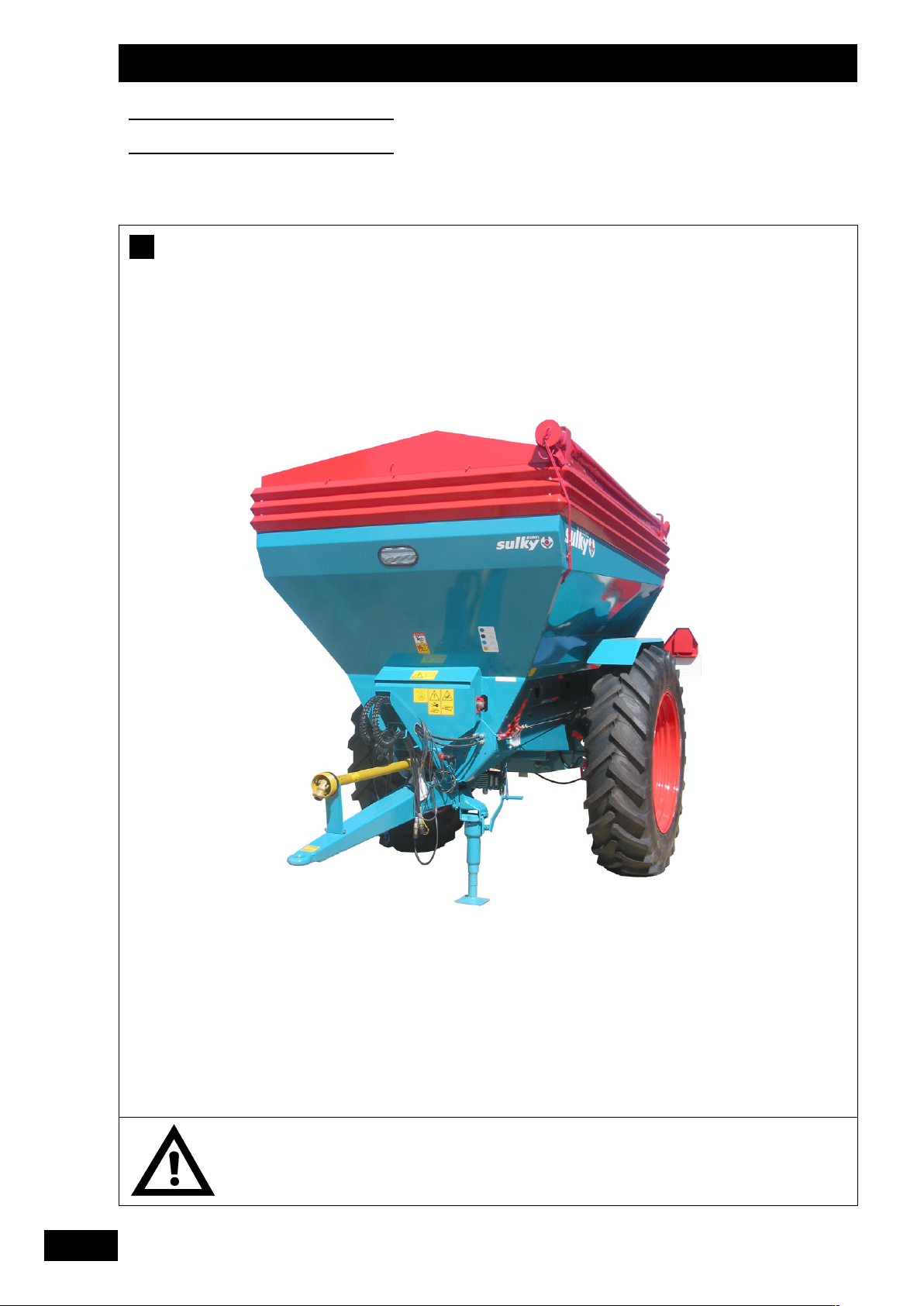
Thank you for choosing the DPA XLT
fertilizer spreader.
To ensure correct operation, and to get the
most out of your spreader, we recommend
that you read these instructions carefully.
Please do not hesitate to give us your
suggestions and comments based on your
experience. They are always useful for
improving our products.
We would be grateful if you could return
the duly completed guarantee coupon.
We hope your fertilizer spreader will
provide long and trouble-free service.
Yours sincerely.
J. BUREL
Chairman and Managing Director
Geehrter Kunde,
Sie haben einen DPA XLT Düngerstreuer
gewählt, und wir danken Ihnen für das in
unsere Geräte gesetzte Vertrauen.
Bitte lesen Sie die Anleitung sorgfältig
durch, damit Sie ihre Düngerstreuer richtig
benutzen und alle ihre Möglichkeiten voll
nutzen können.
Zögern Sie nicht, uns Ihre eigenen
Beobachtungen und Erfahrungen
mitzuteilen, die für die Verbesserung
unserer Produkte immer nützlich sein
können.
Garantieschein bitte ausgefüllt an uns
zurückschicken.
Wir wünschen Ihnen viel Erfolg mit Ihrem
Düngerstreuer und verbleiben
mit freundlichen Grüßen
J. BUREL
Generaldirektor-Präsident
Dear Customer
Geehrter Kunde
Cher Client,
Vous avez choisi l’épandeur
DDPPAA XXLLTT
, et nous vous
remercions de votre confiance pour notre matériel.
Pour une bonne utilisation, et pour tirer profit de toutes
les capacités de votre épandeur, nous vous recommandons
de lire attentivement cette notice.
De par votre expérience, n’hésitez pas à nous faire part
de vos observations et suggestions, toujours utiles pour
l’amélioration de nos produits.
Nous vous saurions gré de nous retourner
llee bboonn ddee
GGaarraannttiiee ddûûmmeenntt rreemmppllii
.
En vous souhaitant bon usage de votre épandeur d’engrais,
Veuillez agréer, Cher Client, l’assurance de nos meilleurs
sentiments.
JJ.. BBUURREELL
Président Directeur Général
GB DE
Page 3
2
LA MACHINE RÉPOND AUX
DISPOSITIONS SUIVANTES :
DIRECTIVE MACHINE
EUROPÉENNE 98/37 CE 97/23 CE
89/336 / CEE
L
ES NORMES EUROPÉENNES SUIVANTES ONT
ÉTÉ UTILISÉES :
EN 292-1 NF EN 292-2
NF EN 1553
T
HE MACHINE COMPLIES WITH THE REVELANT
ESSENTIAL HEALTH AND SAFETY
REQUIREMENTS OF THE
Directive 98/37 EC 97/23 EC
89/336 / EEC
THE FOLLOWING TRANSPOSED HARMONISED
STANDARDS AND
/OR TECHNICAL
SPECIFICATIONS HAVE BEEN USED:
EN 292 PART 1 EN 292 PART 2
EN 1553
D
IE MASCHINE ENTSPRICHT DEN
FOLGENDEN VORSCHRIFTEN:
EG- Maschinen-Richtlinie 98/37
97/23
89/336
FOLGENDE EUROPÄISCHE
NORMEN WURDEN HERANGEZOGEN:
EN 292-1 EN 292-2
EN 1553
Déclaration de Conformité
Declaration of Conformity
Konformitätserklärung
Selon Article 5 annexe 2 point A de la directive européene 89/392/CE et additif
Following article 5 annex 2 poInt A of the Directive 89/392/ EEC and additions
Gemäss Artikel 5 und Anhang 2, Punkt A der EG-Richtlinie 89/392/EG und Zusatz
Fabriqué pour SULKY BUREL
BP 92111 - 35221 Châteaubourg Cedex - France
par SIRTEC
21, rue Jean Monnet
28630 F
ONTENAY-SUR-EURE FRANCE
Nom du Fabricant :
Manufacturer’s name:
Name des Herstellers:
Description de la Machine :
--
Machine Description:
--
Beschreibung der Maschine:
--
Type :
Type:
Typ:
Epandeur
Spreader
Düngerstreuer
DPA -XLT
Numéro de Série :
Serial number:
Serien-Nummer:
Accessoires :
--
Accessories:
--
Zusatzausrüstungen:
--
Fait à Châteaubourg le 24 Octobre 2001
Established in Châteaubourg, on 24 October 2001
Ausgestellt in Châteaubourg am 24 Oktober 2001
Signed:
Befugter Verantwortlicher:
J. BUREL
Président Directeur Général
Managing Director
Generaldirektor-Präsident
FR
GB
DE
Page 4

3
PPRREESSCCRRIIPPTTIIOONNSS GGÉÉNNÉÉRRAALLEESS DDEE SSÉÉCCUURRIITTÉÉ
Avant chaque utilisation et mise en service de
l’ensemble tracteur-machine, s’assurer de sa
conformité avec la réglementation en matière de
sécurité du travail et avec les dispositions du Code
de la Route.
GGÉÉNNÉÉRRAALLIITTÉÉSS
1 - Respecter, en plus des instructions contenues
dans cette notice, la législation relative aux
prescriptions de sécurité et de prévention des
accidents.
2 - Les avertissements apposés sur la machine
fournissent des indications sur les mesures de
sécurité à observer et contribuent à éviter les
accidents.
3 - Lors de la circulation sur la voie publique,
respecter les prescriptions du Code de la Route.
4 - Avant de commencer le travail, l’utilisateur
devra se familiariser obligatoirement avec les
organes de commande et de manœuvre de la
machine et leurs fonctions respectives. En cours
de travail, il sera trop tard pour le faire.
5 - L’utilisateur doit éviter de porter des vêtements
flottants qui risqueraient d’être happés par des
éléments en mouvement.
6 - Il est recommandé d’utiliser un tracteur équipé
d’une cabine ou d’un arceau de sécurité, aux
normes en vigueur.
7 - Avant la mise en route de la machine et le
démarrage des travaux, contrôler les abords
immédiats (enfant !).
Veiller à avoir une visibilité suffisante ! Eloigner
toute personne ou animal de la zone de danger de
la machine (projections !).
8 - Le transport de personnes ou d’animaux sur la
machine lors du travail ou lors des déplacements
est strictement interdit.
9 - L’accouplement de la machine au tracteur ne
doit se faire que sur les points d’attelage prévus à
cet effet conformément aux normes de sécurité
en vigueur.
10 - La prudence est de rigueur lors de l’attelage
de la machine au tracteur et lors de son
désaccouplement !
11 - Avant d’atteler la machine, il conviendra de
s’assurer que le lestage de l’essieu avant du
tracteur est suffisant. La mise en place des masses
de lestage doit se faire sur les supports prévus à
cet effet conformément aux prescriptions du
constructeur du tracteur.
12 - Respecter la charge à l’essieu maximum et le
poids total roulant autorisé en charge.
13 - Respecter le gabarit maximum sur la voie
publique.
14 - Avant de s’engager sur la voie publique,
veiller à la mise en place et au bon
fonctionnement des protecteurs et dispositifs de
signalisation (lumineux, réfléchissants…) exigés
par la loi.
15 - Toutes les commandes à distance (corde,
câble, tringle, flexible…) doivent être positionnées
de telle sorte qu’elles ne puissent déclencher
accidentellement une manœuvre génératrice de
risque d’accident ou de dégâts.
16 - Avant de s’engager sur la voie publique,
placer la machine en position de transport,
conformément aux indications du constructeur.
17 - Ne jamais quitter le poste de conduite
lorsque le tracteur est en marche.
18 - La vitesse et le mode de conduite doivent
toujours être adaptés aux terrains, routes et
chemins. En toute circonstance, éviter les
brusques changements de direction.
19 - La précision de la direction, l’adhérence du
tracteur, la tenue de route et l’efficacité des
dispositifs de freinage sont influencées par des
facteurs tels que : poids et nature de la machine
attelée, lestage de l’essieu avant, état du terrain ou
de la chaussée. Il est donc impératif de veiller au
respect des règles de prudence dictées par
chaque situation.
20 - Redoubler de prudence dans les virages en
tenant compte du porte-à-faux, de la longueur, de
la hauteur et du poids de la machine ou de la
remorque attelée.
21 - Avant toute utilisation de la machine,
s’assurer que tous les dispositifs de protection
sont en place et en bon état. Les protecteurs
endommagés doivent être immédiatement
remplacés.
22 - Avant chaque utilisation de la machine,
contrôler le serrage des vis et des écrous, en
particulier de ceux qui fixent les outils (disques,
palettes, déflecteurs…). Resserrer si nécessaire.
23 - Ne pas stationner dans la zone de manœuvre
de la machine.
24 - Attention ! Des zones d’écrasement et de
cisaillement peuvent exister sur les organes
commandés à distance, notamment ceux asservis
hydrauliquement.
25 - Avant de descendre du tracteur, ou
préalablement à toute intervention sur la machine,
couper le moteur, retirer la clé de contact et
attendre l’arrêt complet de toutes les pièces en
mouvement.
26 - Ne pas stationner entre le tracteur et la
machine sans avoir préalablement serré le frein de
parcage et/ou avoir placé des cales sous les
roues.
27 - Avant toute intervention sur la machine,
s’assurer que celle-ci ne puisse être mise en route
accidentellement.
28 - Ne pas utiliser l’anneau de levage pour lever
la machine lorsqu’elle est remplie.
UUTTIILLIISSAATTIIOONN CCOONNFFOORRMMEE DDEE LLAA MMAACCHHIINNEE
Le Distributeur ne doit être utilisé que pour les
travaux pour lesquels il a été conçu.
En cas de dommage lié à l’utilisation de la
machine hors du cadre des applications spécifiées
par le constructeur, la responsabilité de celui-ci
sera entièrement dégagée.
Toute extrapolation de la destination d’origine de la
machine se fera aux risques et périls de
l’utilisateur.
L’utilisation conforme de la machine implique
également :
- le respect des prescriptions d’utilisation,
d’entretien et de maintenance édictées par le
constructeur,
- l’utilisation exclusive de pièces de rechange,
d’équipements et d’accessoires d’origine ou
préconisés par le constructeur.
Le Distributeur ne doit être utilisé, entretenu et
réparé que par des personnes compétentes,
familiarisées avec les caractéristiques et modes
d’utilisation de la machine. Ces personnes doivent
aussi être informées des dangers auxquels elles
pourraient être exposées.
L’utilisateur est tenu au respect scrupuleux de la
réglementation en vigueur en matière de :
- prévention contre les accidents,
- sécurité du travail (Code du Travail),
- circulation sur la voie publique (Code de la
Route).
- Il lui est fait obligation d’observer strictement les
avertissements apposés sur la machine.
- Toute modification de la machine effectuée par
l’utilisateur lui-même ou toute autre personne,
sans l’accord écrit préalable du constructeur
engagera la responsabilité du propriétaire du
matériel modifié.
- Le bruit créé par la machine n’excède pas 70
décibels.
AATTTTEELLAAGGEE
1 - Pendant les phases d’attelage et de dételage,
veiller à ce que l’axe de verrouillage de la béquille
soit correctement verrouillé.
2 - Ne pas se tenir entre le tracteur et la machine,
ni autour de celle-ci pendant l’attelage.
Prescriptions de sécurité
Risque d’accident
Risque d’endommager la machine
Faciliter le travail
● Ces symboles sont utilisés dans cette notice chaque fois que des recommandations concernent votre sécurité, celle d’autrui ou le bon
fonctionnement de la machine.
● Transmettez impérativement ces recommandations à tout utilisateur de la machine.
FR
Page 5

4
ORGANES D’ANIMATION
(Prises de force et arbres de transmission à
cardans)
1 - N’utiliser que les arbres de transmission à
cardans fournis avec la machine ou préconisés par
le constructeur.
2 - Les protecteurs des prises de force et des
arbres de transmission à cardans doivent toujours
être en place et en bon état.
3 - Veiller au recouvrement correct des tubes des
arbres de transmission à cardans, aussi bien en
position de travail qu’en position de transport.
4 - Avant de connecter ou de déconnecter un
arbre de transmission à cardans, débrayer la prise
de force, couper le moteur et retirer la clé de
contact.
5 - Si l’arbre de transmission à cardans primaire
est équipé d’un limiteur de couple ou d’une roue
libre, ceux-ci doivent impérativement être montés
sur la prise de force de la machine.
6 - Veiller toujours au montage et au verrouillage
corrects des arbres de transmission à cardans.
7 - Veiller toujours à ce que les protecteurs des
arbres de transmission à cardans soient
immobilisés en rotation à l’aide des chaînettes
prévues à cet effet.
8 - Avant d’embrayer la prise de force, s’assurer
que le régime choisi et le sens de rotation de la
prise de force sont conformes aux prescriptions du
constructeur.
9 - Avant d’embrayer la prise de force, s’assurer
qu’aucune personne ou animal ne se trouve à
proximité de la machine.
10 - Débrayer la prise de force lorsque les limites
de l’angle de l’arbre de transmission à cardans
prescrites par le constructeur risquent d’être
dépassées.
11 - Attention ! Après le débrayage de la prise de
force, les éléments en mouvement peuvent
continuer à tourner quelques instants encore. Ne
pas s’en approcher avant immobilisation totale.
12 - Lors de la dépose de la machine, faire
reposer les arbres de transmission à cardans sur
les supports prévus à cet effet.
13 - Après avoir déconnecté l’arbre de
transmission à cardans de la prise de force du
tracteur, celle-ci doit être recouverte de son
capuchon protecteur.
14 - Les protecteurs de prise de force et d’arbres
de transmission à cardans endommagés doivent
être remplacés immédiatement.
CIRCUIT HYDRAULIQUE
1 - Attention ! Le circuit hydraulique est sous
pression.
2 - Lors du montage de vérins ou de moteurs
hydrauliques, veiller attentivement au branchement
correct des circuits, conformément aux directives
du constructeur.
3 - Avant de brancher un flexible au circuit
hydraulique du tracteur, s’assurer que les circuits
côté tracteur et côté machine ne sont pas sous
pression.
4 - Il est vivement recommandé à l’utilisateur de la
machine de suivre les repères d’identification sur
les raccords hydrauliques entre le tracteur et la
machine afin d’éviter des erreurs de branchement.
Attention ! Il y a risque d’interversion des fonctions
(par exemple : relever/abaisser).
5 - Contrôler une fois par an les flexibles
hydrauliques :
. Blessure de la couche extérieure
. Porosité de la couche extérieure
. Déformation sans pression et sous pression
. Etat des raccords et des joints
La durée d’utilisation maximum des flexibles est de
6 ans. Lors de leur remplacement, veiller à n’utiliser
que des flexibles de caractéristiques et de qualité
prescrits par le constructeur de la machine.
6 - Lors de la localisation d’une fuite, il conviendra
de prendre toute précaution visant à éviter les
accidents.
7 - Tout liquide sous pression, notamment l’huile
du circuit hydraulique, peut perforer la peau et
occasionner de graves blessures ! En cas de
blessure, consulter de suite un médecin ! Il y a
danger d’infection !
8 - Avant toute intervention sur le circuit
hydraulique, abaisser la machine, mettre le circuit
hors pression, couper le moteur et retirer la clé de
contact.
ENTRETIEN
1 - Avant tous travaux de maintenance, d’entretien
ou de réparation, ainsi que lors de la recherche de
l’origine d’une panne ou d’un incident de
fonctionnement, il faut impérativement que la prise
de force soit débrayée, que le moteur soit coupé
et la clé de contact retirée.
2 - Contrôler régulièrement le serrage des vis et
des écrous. Resserrer si nécessaire !
3 - Avant de procéder à des travaux d’entretien
sur une machine en position relevée, étayer celleci à l’aide d’un moyen approprié.
4 - Lors du remplacement d’une pièce travaillante,
(pale pour les distributeurs ou socs pour les
semoirs), mettre des gants de protection et
n’utiliser qu’un outillage approprié.
5 - Pour la protection de l’environnement, il est
interdit de jeter ou de déverser les huiles, graisses
et filtres en tout genre. Les confier à des
entreprises spécialisées dans leur récupération.
6 - Avant toute intervention sur le circuit
électrique, déconnecter la source d’énergie.
7 - Les dispositifs de protection susceptibles
d’être exposés à une usure doivent être contrôlés
régulièrement. Les remplacer immédiatement s’ils
sont endommagés.
8 - Les pièces de rechange doivent répondre aux
normes et caractéristiques définies par le
constructeur. N’utiliser que des pièces de
rechange Sulky !
9 - Avant d’entreprendre des travaux de soudure
électrique sur le tracteur ou la machine attelée,
débrancher les câbles de l’alternateur et de la
batterie.
10 - Les réparations affectant les organes sous
tension ou pression (ressorts, accumulateurs de
pression, etc) impliquent une qualification
suffisante et font appel à un outillage spécifique ;
aussi ne doivent-elles être effectuées que par un
personnel qualifié.
DANGER
Disque en rotation
Projection d’engrais
Pression hydraulique
Risque d’écrasement attelage
FR
Page 6

5
Safety regulations
Risk of accident
Risk of damage to the machine
Operating tip
● These symbols are used in these instructions every time recommendations are provided concerning your safety, the safety of others or the
correct operation of the machine.
● These recommendations must be given to all users of the machine.
GGEENNEERRAALL SSAAFFEETTYY RREEGGUULLAATTIIOONNSS
Every time the tractor/machine assembly is to be
started up and used, you should ensure
beforehand that it complies with current legislation
on safety at work and Road Traffic regulations.
GGEENNEERRAALL
1 - In addition to the instructions contained in this
manual, legislation relating to safety instructions
and accident prevention should be complied with.
2 - Warnings affixed to the machine give
indications regarding safety measures to be
observed and help to avoid accidents.
3 - When travelling on public roads, abide by the
provisions of the Highway Code.
4 - Before starting work, it is essential that the
user familiarizes himself with the control and
operating elements of the machine and their
respective functions. When the machine is
running, it may be too late.
5 - The user should avoid wearing loose clothing
which may be caught up in the moving parts.
6 - We recommend using a tractor with a safety
cab or roll bar conforming to standards in force.
7 - Before starting up the machine and beginning
work, check the immediate surroundings,
particularly for children. Make sure that visibility is
adequate. Clear any persons or animals out of the
danger zone.
8 - It is strictly forbidden to transport any persons
or animals on board the machine whether it is in
operation or not.
9 - The machine should only be coupled up to the
tractor at the specially provided towing points and
in accordance with applicable safety standards.
10 - Extreme care must be taken when coupling
or uncoupling the machine from the tractor.
11 - Before hitching up the machine, ensure that
the front axle of the tractor is sufficiently
weighted. Ballast weights should be fitted to the
special supports in accordance with the
instructions of the tractor manufacturer.
12 - Do not exceed the maximum axle weight or
the gross vehicle weight rating.
13 - Do not exceed the maximum authorized
dimensions for using public roads.
14 - Before entering a public road, ensure that
the protective and signalling devices (lights,
reflectors, etc.) required by law are fitted and
working properly.
15 - All remote controls (cords, cables, rods,
hoses, etc.) must be positioned so that they
cannot accidentally set off any manoeuvre which
may cause an accident or damage.
16 - Before entering a public road, place the
machine in the transport position, in accordance
with the manufacturer’s instructions.
17 -. Never leave the driver’s position whilst the
tractor is running.
18 - The speed and the method of operation must
always be adapted to the land, roads and paths.
Avoid sudden changes of direction under all
circumstances.
19 - Precision of the steering, tractor adhesion,
road holding and effectiveness of the braking
mechanism are influenced by factors such as the
weight and nature of the machine being towed,
the front axle stage and the state of the land or
path. It is essential, therefore, that the appropriate
care is taken for each situation.
20 - Take extra care when cornering, taking
account of the overhang, length, height and
weight of the machine or trailer being towed.
21 - Before using the machine, ensure that all
protective devices are fitted and in good condition.
Damaged protectors should be replaced
immediately.
22 - Before using the machine, check that nuts
and screws are tight, particularly those for
attaching tools (discs, flickers, deflectors, etc.).
Tighten if necessary.
23 - Do not stand in the operating area of the
machine.
24 - Caution! Be aware of any crushing and
shearing zones on remote-controlled and
particularly hydraulically-controlled parts.
25 - Before climbing down from the tractor, or
before any operation on the machine, turn off the
engine, remove the key from the ignition and wait
until all moving parts have come to a standstill.
26 - Do not stand between the tractor and the
machine until the handbrake has been applied
and/or the wheels have been wedged.
27 -. Before any operation on the machine, ensure
that it
cannot be started up accidentally.
28 - Do not use the lifting ring to lift the machine
when it is loaded.
PPRROOPPEERR UUSSEE OOFF TTHHEE MMAACCHHIINNEE
The Spreader must only be used for tasks for
which it has been designed.
The manufacturer will not be liable for any damage
caused by using the machine for applications
other than those specified by the manufacturer.
Using the machine for purposes other than those
originally intended will be done so entirely at the
user’s risk.
Proper use of the machine also implies:
- complying with instructions on use, care and
maintenance provided by the manufacturer;
- using only original or manufacturer
recommended spare parts, equipment and
accessories.
The Spreader must only be operated, maintained
and repaired by competent persons, familiar with
the specifications and methods of operation of the
machine. These persons must also be informed of
the dangers to which they may be exposed.
The user must strictly abide by current legislation
regarding:
- accident prevention;
- safety at work (Health and Safety Regulations);
- transport on public roads (Road Traffic
Regulations).
Strict compliance with warnings affixed to the
machine is obligatory.
The owner of the equipment shall become liable
for any damage resulting from alterations made to
the machine by the user or any other person,
without the prior written consent of the
manufacturer.
The noise created by the machine does not
exceed 70 decibels.
HHIITTCCHHIINNGG
1 - During the hitching and unhitching operations,
check that the stand locking pin is correctly
locked.
2 - Make sure that no-one stands between the
tractor and the machine, nor around them during
hitching.
DDRRIIVVEE EEQQUUIIPPMMEENNTT
(Power take-off and universal drive shafts)
1 - Only use universal drive shafts supplied with
the machine or recommended by the
manufacturer.
2 - Power take-off and universal drive shaft
guards must always be fitted and in good
condition.
3 - Ensure that the tubes of the universal drive
shafts are properly guarded, both in the working
position and in the transport position.
4 - Before connecting or disconnecting a universal
drive shaft, disengage the power take-off, turn off
the engine and re-move the key from the ignition.
5 - If the primary universal drive shaft is fitted with
a torque limiter or a free wheel, these must be
mounted on the machine power take-off.
6 - Always ensure that universal drive shafts are
fitted and locked correctly.
7 - Always ensure that universal drive shaft guards
are immobilized in rotation using the specially
provided chains.
GB
Page 7

6
8 - Before engaging power take-off, ensure that
the speed selected and the direction of rotation of
the power take-off comply with the
manufacturer’s instructions.
9 - Before engaging power take-off, ensure that
no persons or animals are close to the machine.
10 - Disengage power take-off when the universal
drive shaft angle limits laid down by the
manufacturer are in danger of being exceeded.
11 - Caution! When power take-off has been
disengaged, moving parts may continue to rotate
for a few moments. Do not approach until they
have reached a complete standstill.
12 - On removal from the machine, rest the
universal drive shafts on the specially provided
supports.
13 - After disconnecting the universal drive shafts
from the power take-off, the protective cap should
be fitted to the power take-off.
14 - Damaged power take-off and universal drive
shaft guards must be replaced immediately.
HHYYDDRRAAUULLIICC CCIIRRCCUUIITT
1 - Caution! The hydraulic circuit is pressurized.
2 - When fitting hydraulic motors or cylinders,
ensure that the circuits are connected correctly in
accordance with the manufacturer’s guidelines.
3 - Before fitting a hose to the tractor’s hydraulic
circuit, ensure that the tractor-side and machineside circuits are not pressurized.
4 - The user of the machine is strongly
recommended to identify the hydraulic couplings
between the tractor and the machine in order to
avoid wrong connection. Caution! There is a
danger of reversing the functions (for example:
raise/lower).
5 - Check hydraulic hoses once a year:
. Damage to the outer surface
. Porosity of the outer surface
. Deformation with and without pressure
. State of the fittings and seals
The maximum working life for hoses is 6 years.
When replacing them, ensure that only hoses with
the specifications and grade recommended by the
machine manufacturer are used.
6 - When a leak is found, all necessary
precautions should be taken to avoid accidents.
7 - Pressurized liquid, particularly hydraulic circuit
oil, may cause serious injury if it comes into
contact with the skin. If the case of injury, consult
a doctor immediately. There is a risk of infection.
8 - Before any operation on the hydraulic circuit,
lower the machine, release the pressure from the
circuit, turn off the engine and remove the key
from the ignition.
MMAAIINNTTEENNAANNCCEE
1 - Before commencing any maintenance,
servicing or repair work, or before attempting to
locate the source of a breakdown or fault, it is
essential that the power take-off is disengaged,
the engine turned off and the key removed from
the ignition.
2 - Check regularly that nuts and screws are not
loose. Tighten if necessary.
3 - Before carrying out maintenance work on a
raised machine, prop it up using appropriate
means of support.
4 - When replacing a working part (fertilizer
spreader blade or seed drill coulter), wear
protective gloves and only use appropriate tools.
5 - To protect the environment, it is forbidden to
throw away oil, grease or filters of any kind. Give
them to specialist recycling firms.
6 - Before operating on the electric circuit,
disconnect the power source.
7 - Protective devices likely to be exposed to wear
and tear should be checked regularly. Replace
them immediately if they are damaged.
8 - Spare parts should comply with the standards
and specifications laid down by the manufacturer.
Only use Sulky spare parts.
9 - Before commencing any electric welding work
on the tractor or the towed machine, disconnect
the alternator and battery cables.
10 - Repairs affecting parts under stress or
pressure (springs, pressure accumulators, etc.)
should be carried out by suitably qualified
engineers with special tools.
DANGER
Rotating disc
Projection of fertilizer
Hydraulic pressure
Risk of pinching or
crushing
GB
Page 8

7
Sicherheitsvorschriften
Verletzungsgefahr
Gefahr der Beschädigung der Maschine
Hinweis zur Erleichterung der Arbeit
● In der Anweisung werden diese Zeichen in Verbindung mit Empfehlungen für Ihre Sicherheit und der anderer sowie die gute Funktion der
Maschine verwendet.
● Jeder Benutzer dieser Maschine muß diese Vorschriften genau kennen.
AALLLLGGEEMMEEIINNEE SSIICCHHEERRHHEEIITTSSVVOORRSSCCHHRRIIFFTTEENN
Vor jeder Benutzung und Inbetriebsetzung der
Schlepper-Maschine-Einheit kontrollieren, ob sie
den Sicherheitsvorschriften und den Vorschriften
der Straßenverkehrsordnung entsprechen.
AALLLLGGEEMMEEIINNEESS
1 - Zusätzlich zu den in diesem Handbuch
enthaltenen Anweisungen die Gesetzgebung
bezüglich der Sicherheits- und
Unfallverhütungvorschriften einhalten.
2 - Die auf der Maschine angebrachten
Warnungen informieren über die einzuhaltenden
Sicherheitsmaßnahmen und tragen zur
Unfallverhütung bei.
3 - Im Straßenverkehr die
Straßenverkehrsordnung einhalten.
4 - Vor Arbeitsbeginn muß sich der Benutzer
unbedingt mit den Antriebs- und
Bedienungsorganen der Maschine und ihren
jeweiligen Funktionen vertraut machen. Während
der Arbeit ist es dafür zu spät.
5 - Weite Kleidungsstücke, die in sich bewegende
Teile geraten könnten, vermeiden.
6 - Es empfiehlt sich, gemäß den gültigen Normen
einen Schlepper mit Kabine oder
Sicherheitsverstärkung zu verwenden.
7 - Vor Inbetriebsetzung und Arbeitsbeginn die
direkte Umgebung kontrollieren (Kind !). Für
ausreichende Sicht sorgen! Personen oder Tiere
aus dem Maschinengefahrenbereich entfernen
(Schutzvorrichtungen !).
8 - Der Transport von Personen oder Tieren auf
der Maschine ist während der Arbeit oder beim
Fahren streng verboten.
9 - Die Maschine darf gemäß den geltenden
Sicherheitsnormen nur an den dafür vorgesehenen
Kupplungspunkten angehängt werden.
10 - Besondere Vorsicht ist beim An- und Abbau
der Maschine am Schlepper geboten.
11 - Vor Anhängen der Maschine kontrollieren, ob
der Ballast des Schleppers genügt. Die
Ballastelemente müssen gemäß den Vorschriften
des Schlepperherstellers auf den dafür
vorgesehenen Haltern angebracht werden.
12 - Die maximale Achslast und das zulässige
Gesamtgewicht einhalten.
13 - Das für den Straßenverkehr maximal
zulässige Außenmaß einhalten.
14 - Vor Straßenbenutzung die
Schutzvorrichtungen und
Signalisierungsvorrichtungen (Licht- und
Rückstrahlelemente) anbringen und ihre Funktion
prüfen.
15 - Alle Fernsteuerungen (Seil, Kabel, Stange,
Schlauch) müssen so positioniert sein, daß sie
nicht ungewollt betätigt werden und dadurch
Unfälle oder Schäden hervorrufen können.
16 - Vor Benutzung der Straße die Maschine
gemäß Herstelleranweisungen in Transportstellung
bringen.
17 -. Fahrersitz nie bei laufender Maschine
verlassen.
18 - Fahrgeschwindigkeit und -weise müssen
immer dem Gelände, den Straßen und Wegen
angepaßt sein. Auf alle Fälle plötzliche
Richtungsänderungen vermeiden.
19 - Die Präzision der Lenkung, die Bodenhaftung
des Schleppers, die Straßenlage und die
Wirksamkeit der Bremsvorrichtungen werden
beeinflußt von Faktoren wie: Gewicht und Art der
angebauten Maschine, Belastung der Vorderachse,
Zustand des Geländes oder der Fahrbahn. Die den
Bedingungen entsprechenden
Vorsichtsmaßnahmen einhalten.
20 - Besondere Vorsicht ist in Kurven geboten.
Schwerpunktlage, Länge, Höhe und Gewicht der
Maschine oder des Anhängers berücksichtigen.
21 - Vor jeder Benutzung der Maschine
kontrollieren, ob alle Schutzvorrichtungen
angebracht und in gutem Zustand sind. Bei
Beschädigung sofort austauschen.
22 - Vor jeder Benutzung kontrollieren, ob alle
Schrauben und Muttern fest angezogen sind,
insbesondere die, mit denen die Geräte befestigt
sind (Scheiben, Paletten, Schirme...). Notfalls
anziehen.
23 - Sich nicht im Manövrierbereich der Maschine
aufhalten.
24 - Vorsicht! Auf den Fernsteuerungsorganen,
insbesondere auf denen mit hydraulischem
Regelkreis, kann es Stauch- und Abscherzonen
geben.
25 - Vor Verlassen des Schleppers oder vor jedem
Eingriff auf der Maschine Motor abschalten,
Zündschlüssel abziehen und völligen Stillstand
aller bewegten Teile abwarten.
26 - Sich nicht zwischen Schlepper und Maschine
aufhalten, ohne zuvor die Parkbremse angezogen
und/oder Keile unter die Räder gelegt zu haben.
27 - Vor jedem Eingriff an der Maschine
kontrollieren, ob diese nicht ungewollt in Betrieb
gesetzt werden kann.
28 - Die Aufhängöse nicht zum Heben der
gefüllten Maschine benutzen.
BBEESSTTIIMMMMUUNNGGSSGGEEMMÄÄßßEE VVEERRWWEENNDDUUNNGG DDEERR
MMAASSCCHHIINNEE
Der Rotorstreuer darf nur für die Arbeiten
eingesetzt werden, für die sie geplant ist.
Bei Beschädigung der Maschine infolge einer
nicht vom Hersteller spezifizierten Benutzung ist
dieser nicht haftbar.
Jede nicht der ursprünglichen Bestimmung der
Maschine entsprechende Benutzung erfolgt auf
Rechnung und Gefahr des Benutzers.
Die bestimmungsgemäße Verwendung der
Maschine setzt ebenfalls voraus:
- die Einhaltung der vom Hersteller verordneten
Benutzungs-, Wartungs- und
Instandsetzungsvorschriften,
- die ausschließliche Verwendung von
Originalersatzteilen, Originalausrüstungen und
Originalzubehör oder von Teilen, die vom Hersteller
empfohlen sind.
Der Rotorstreuer darf nur von kompetenten, mit
den technischen Daten und
Benutzungsanweisungen der Maschine vertrauten
Personen benutzt, gewartet und repariert werden,
die über die Risiken informiert sind, denen sie
ausgesetzt sein könnten.
Streng die gültige Reglementierung einhalten
bezüglich:
- der Unfallverhütung,
- der Arbeitssicherheit (Arbeitsgesetzbuch)
- des Straßenverkehrs (Straßenverkehrsordnung).
Die auf der Maschine angebrachten Warnungen
berücksichtigen.
Der Hersteller haftet nicht für Schäden, die durch
Abänderungen entstehen, die vom Benutzer selbst
oder von Dritten ohne schriftliche Genehmigung
an der Maschine vorgenommen wurden.
Das von der Maschine hervorgerufene Geräusch
liegt unter 70 Dezibel.
AANNHHÄÄNNGGUUNNGG
1 - Beim An- oder Abkoppeln darauf achten, dass
die Verriegelungsachse der Stütze richtig verriegelt
ist.
2 - Achten Sie darauf, dass sich beim
Ankopplungsvorgang niemand im bzw. um den
Maschinenbereich zwischen Schlepper und
Maschine aufhält.
AANNTTRRIIEEBBSSOORRGGAANNEE
(Zapfwelle und Gelenkwellen-Antrieb)
1 - Nur die mit der Maschine gelieferte oder vom
Konstrukteur empfohlene Gelenkwelle verwenden.
2 - Die Schutzvorrichtungen der Zapfwellen und
Gelenkwellen müssen immer angebracht und in
gutem Zustand sein.
3 - Auf die richtige Überlappung der
Gelenkwellenrohre sowohl in Arbeits- als auch in
Transportstellung achten.
4 - Vor Anschließen oder Abziehen einer
Gelenkwelle die Zapfwelle auskuppeln, den Motor
DE
Page 9

8
abschalten und den Zündschlüssel abziehen.
5 - Ist die Primärkardanwelle mit einem
Drehmomentbegrenzer oder einer
Freilaufkupplung ausgestattet, müssen diese
unbedingt auf der Zapfwelle der Maschine
montiert sein.
6 - Immer auf die korrekte Montage und
Verriegelung der Kardanantriebe achten.
7 - Immer darauf achten, daß die
Schutzvorrichtungen der Gelenkwellen mit den
dafür vorgesehenen Ketten gegen Verdrehen
gesichert sind.
8 - Vor Kuppeln der Zapfwelle prüfen, ob die
gewählte Drehzahl und die Drehrichtung der
Zapfwelle den Vorschriften des Herstellers
entsprechen.
9 - Vor Kuppeln der Zapfwelle kontrollieren, ob
sich keine Personen oder Tiere in Nähe der
Maschine befinden.
10 - Die Zapfwelle auskuppeln, wenn Gefahr
besteht, daß die vom Hersteller vorgeschriebenen
Grenzen des Gelenkwellenwinkels überschritten
werden.
11 - Vorsicht! Nach Auskuppeln der Zapfwelle
können Teile der Maschine noch einige Zeit
nachlaufen. Sich ihnen nie vor völligem Stillstand
nähern.
12 - Bei Abbau der Maschine die Gelenkwellen
auf den dafür vorgesehenen Haltern ablegen.
13 - Nach Abziehen der Gelenkwelle von der
Schlepperzapfwelle muß diese mit ihrer
Schutzkappe bedeckt werden.
14 - Schadhafte Schutzvorrichtungen der
Zapfwelle und der Gelenkwelle müssen sofort
ausgewechselt werden.
HHYYDDRRAAUULLIIKKLLEEIITTUUNNGG
1 - Vorsicht! Die Hydraulikleitung steht unter
Druck.
2 - Bei Montage von Zylindern oder
Hydraulikmotoren auf den korrekten Anschluß
gemäß Anweisungen des Herstellers achten.
3 - Vor Anschluß eines Schlauches an der
Hydraulikleitung des Schleppers dafür sorgen, daß
die schlepper- und maschinenseitigen Leitungen
nicht unter Druck stehen.
4 - Dem Benutzer der Maschine wird zur
Vermeidung falscher Anschlüsse dringend geraten,
die Kennzeichnungen auf den
Hydraulikanschlüssen zwischen Schlepper und
Maschine zu beachten, da sonst die Gefahr einer
Funktionsumkehrung besteht. (z.B.:
Heben/Senken).
5 - Einmal im Jahr die Hydraulikschläuche
kontrollieren auf:
. Beschädigung der Außenschicht
. Porosität der Außenschicht
. Verformung ohne Druck und unter Druck
. Zustand der Verbindungen und Dichtungen.
Die maximale Benutzungsdauer der Schläuche ist
6 Jahre. Beim Auswechseln darauf achten, daß
nur Schläuche verwendet werden, deren
Eigenschaften und Qualität den Vorschriften des
Maschinenkonstrukteurs entsprechen.
6 - Bei Feststellung einer undichten Stelle alle
Vorsichtsmaßnahmen zur Unfallverhütung treffen.
7 - Eine unter Druck stehende Flüssigkeit,
insbesondere das Öl der Hydraulikleitung, kann die
Haut durchdringen und schwere Verletzungen
verursachen! Bei Verletzungen sofort Arzt
konsultieren; Infektionsgefahr!
8 - Vor jedem Eingriff in die Hydraulikanlage
Maschine ablassen, Anlage drucklos schalten,
Motor abstellen und Zündschlüssel abziehen.
WWAARRTTUUNNGG
1 - Vor Instandsetzungs-, Wartungs- oder
Reparaturarbeiten sowie bei Ermitteln einer
Pannen- oder Betriebsstörungsquelle muß die
Zapfwelle ausgekuppelt, der Motor abgeschaltet
und der Zündschlüssel abgezogen sein.
2 - Regelmäßig kontrollieren, ob Schrauben und
Muttern fest angezogen sind. Notfalls anziehen.
3 - Vor Wartung einer Maschine in angehobener
Stellung diese mit einem geeigneten Mittel
abstützen.
4 - Beim Austausch eines Funktionsteiles
(Schaufel bei Streuern oder Schare bei
Drillmaschinen) Schutzhandschuhe tragen und nur geeignete Werkzeuge
benutzen.
5 - Zum Schutz der Umwelt ist es verboten, Öl,
Fett und Filter jeder Art wegzuwerfen oder
auszugießen. Sie sind von darauf spezialisierten
Unternehmen zu entsorgen.
6 - Vor Eingriff an der elektrischen Leitung die
Stromzufuhr unterbrechen.
7 - Verschleiß ausgesetzte Schutzvorrichtungen
müssen regelmäßig kontrolliert werden. Sie sofort
austauschen, wenn schadhaft.
8 - Ersatzteile müssen den vom Konstrukteur
festgelegten Normen und Kennwerten
entsprechen. Nur Sulky-Ersatzteile verwenden!
9 - Vor Elektroschweißarbeiten am Schlepper oder
der angehängten Maschine die Kabel des
Wechselstromgenerators und der Batterie
abziehen.
10 - Reparaturen an Organen, die unter Spannung
oder Druck stehen (Federn, Druckspeicher, usw...)
setzen eine ausreichende Qualifikation voraus und
erfordern Werkzeuge; sie dürfen daher nur von
qualifiziertem Personal durchgeführt werden.
GEFAHR
Scheibe in Bewegung
Düngerauswurf
Hydraulikdruck
Stauchgefahr Kupplung
DE
Page 10

9
Pages
MISE EN ROUTE
SSOOMMMMAAIIRREE
Français
12-13
14-15
14-17
Pages
REGLAGES
22-23
24-31
32-45
46-47
48-55
• A Réglage de la machine
• B Réglage du débit
• C Réglage largeur
• D Epandage
• E Epandage de bordure
Pages
ENTRETIEN
64-67
68-69
69
• A Entretien pendant la campagne
• B Remisage
• C Avant de recommencer
une saison d'épandage
18
17-18
20-21
• D Pneumatiques
• E Grilles anti-motte
• F Chargement de la trémie
Pages
CARACTERISTIQUES / RECOMMANDATIONS
77
77
• A Identification
• B Caractéristiques Techniques
Lire attentivement la notice avant l’utilisation. Comprendre son épandeur
c’est mieux l’utiliser. En français suivre le symbole.
56-59
60-61
62-63
• F Optimisation bordure
environnement
• G Embrayage et débrayage
du tapis convoyeur
• H Réglage de la voie de l'essieu
Pages
MONTAGE EQUIPEMENTS
74-75
75
• A Bâche enrouleur
• B Réhausse
70-71
72-73
• D Vérification double disques
• E Contrôle étalonnage
Pages
REGLAGE LARGEUR
78
81
82-101
• Conseils généraux
• Listes des produits
• Tableaux réglage largeur
• A Transport et réception du
matériel
• B Attelage
• C Prise de force
1
FR
2
3
4
5
6
Page 11

10
Read the manual carefully before use. Better understanding
means better and safer spreading. For English follow the symbol.
CONTENTS
English
Pages
START-UP
12-13
14-15
14-17
Pages
SETTINGS
22-23
24-31
32-45
46-47
48-55
• A Machine settings
• B Adjusting the flow rate
• C Width adjustment
• D Spreading
• E Border spreading
Pages
MAINTENANCE
64-67
68-69
69
• A Maintenance during the
season
• B Storage
• C Before the start of a new
spreading season
18
17-18
20-21
• D Tyres
• E
Anti-clod screens
• F Loading the hopper
Pages
SPECIFICATIONS
77
77
• A Identification
• B Technical specifications
Pages
FITTING THE ACCESSORIES
74-75
75
• A The cover spool
• B The hopper extension
70-71
72-73
• D Checking the twin discs
• E Width calibration checks
Pages
WIDTH ADJUSTMENT
78
81
82-101
• General Recommendations
• Product-list
• Width adjustment table
• A Transport and delivery
• B Hitching
• C Power take-off
56-59
60-61
62-63
• F Environmental Border
optimising
• G Engaging and disengaging the
conveyor belt
• H Adjusting the axle track
GB
Page 12

11
VVEERRZZEEIICCHHNNIISS
Deutsch
Anweisung vor Benutzung sorgfältig durchlesen. Die Düngerstreuer
verstehen, heißt sie besser benutzen. Die deutsche Fassung ist mit
gekennzeichnet.
Seite
INBETRIEBSETZUNG
12-13
14-15
14-17
Seite
EINSTELLUNGEN
22-23
24-31
32-45
46-47
48-55
• A Einstellung der Maschine
• B Streumengeneinstellung
• C Einstellungen Arbeitsbreiten
• D Ausbringung
• E Grenzstreuung
Seite
WARTUNG
64-67
68-69
69
• A Wartung und Pflege während
der Düngekampagne
• B Stillegung bzw. Einwinterung
• C Vor der nächsten Düngesaison
18
17-18
20-21
• D Bereifung
• E
Klumpenschutz
• F Füllen des Trichters
Seite
TECHNISCHE DATEN
77
77
• A Identifizierung
• B Technische Eigenschaften
Seite
MONTAGE DER AUSRÜSTUNGEN
74-75
75
• A Rollplane
• B Trichteraufbau
70-71
72-73
• D Prüfung der
Doppelstreuscheiben
• E Prüfung und Einstellung der
Breitenstreuung
Seite
EINSTELLUNGEN ARBEITSBREITEN
78
81
82-101
• Allgemeine Ratschläge
• Produkt-Verzeichnis
• Tabelle Einstellung Arbeitsbreite
• A Transport und Abnahme der
Maschine
• B Ankopplung
• C Zapfwelle
56-59
60-61
62-63
• F Grenzstreung Optimierung
• G Ein- und Auskuppeln des
Förderbandes
• H Spurbreite einstellen
DE
1
2
3
4
5
6
Page 13

12
Mise en route
Start-up
Inbetriebsetzung
A réception de votre
machine, vérifier qu'elle n'a
pas été endommagée
pendant le transport et qu'il
ne manque rien.
Check the machine upon
delivery for any damage that
may have occurred during
transit and for missing parts.
Bei Annahme ihrer
Maschine prüfen, ob die
Maschine nicht während
des Transports beschädigt
wurde und gegenüber dem
Bestellschein kein Teil fehlt.
A
Page 14

13
FR
GB
DE
Transport et réception du matériel
Vérifier soigneusement que votre machine n’a pas été
endommagée pendant le transport et qu’il ne manque
aucune pièce. Eventuellement, faire les réserves nécessaires
sur le récépissé et les confirmer dans un délai de 48 heures
par lettre recommandée au transporteur.
La machine peut être levée par les 4 points d’ancrage situés
aux 4 angles supérieurs de la trémie.
Lors d’un transport, se conformer aux règles de sécurité
suivantes :
- La béquille doit être en position basse,
- Tirer le levier de frein de stationnement,
- Arrimer le matériel sur les «zones de sanglage pour
transport» prévu à cet effet.
Remarques
: Conditions de stockage : à vide sur une pente
inférieure à 10%, freins correctement serrés.
• Vérifications préalables à toute utilisation
Contrôle serrage
Vérifier que tous les boulons de la machine sont bien serrés.
A
TTENTION.
Après 1 heure de travail:
. resserrer les écrous de roues, le couple de serrage doit
être compris entre 19 et 21 m.daN pour les essieux à
8 goujons Ø 18 par tambour.
Après 8 heures de travail:
. vérifier le serrage des roues et des écrous de roues.
A
Mise en route
Start-up
Inbetriebsetzung
Transport and delivery
Check the machine carefully for any damage that may have
occurred during transit and for missing parts. Note any
reserves on the delivery slip and then to the carrier by
recorded delivery letter within 48 hours.
The machine can be raised using the 4 lifting lugs at each
corner of the hopper.
Always observe the following safety instructions when the
machine is being transported:
- The parking stand must be lowered,
- Apply the parking brake,
- Secure the equipment using the “transport strap
attachments” provided.
N
B:Storage conditions: Store the machine empty on a slope
of less than 10%, with the brakes correctly applied.
• Checks before each use
Torque check
Make sure that the bolts are properly tightened.
I
MPORTANT.
After 1 operating hour:
. retighten the wheel nuts to between 19 and 21 m/daN
on axles with 8 x Ø 18 per drum
After 8 operating hours:
. check the tightness of the wheels and the wheel nuts
A
Transport und Abnahme der Maschine
Bei Annahme ihrer Maschine bitte sorgfältig prüfen, ob die
Maschine nicht während des Transports beschädigt wurde
und ob kein Teil fehlt. Eventuelle Vorbehalte auf dem
Empfangsschein vermerken und dem Spediteur innerhalb
von 48 Stunden per Einschreiben bestätigen.
Anheben der Maschine mittels der 4 Verankerungspunkte an
den 4 oberen Ecken des Tanks.
Beim Transport bitte folgende Sicherheitshinweise beachten:
- Die Abstellstütze muss in abgesenkter Position sein.
- Parkbremse ziehen,
- Maschine an den dazu vorgesehenen
„Transportgurtbereichen“ festmachen.
Anmerkungen : Stillegungsbedingungen: leer bei einer
Neigung unter 10%, Parkbremse angezogen.
• Prüfungen vor jedem Maschineneinsatz
Anziehen der Schrauben
Prüfen, dass alle Schrauben und Muttern richtig angezogen
sind.
A
CHTUNG.
Nach 1 Arbeitsstunde:
. Radmuttern anziehen, das Anziehdrehmoment muss
zwischen 19 und 21 m.daN für Achsen mit 8
Stiftbolzen im Ø 18 pro Bremstrommel.
Nach 8 Arbeitsstunden:
. Prüfen, ob die Räder und Radmuttern richtig
angezogen sind.
A
1
Page 15
14
Mise en route
Start-up
Inbetriebsetzung
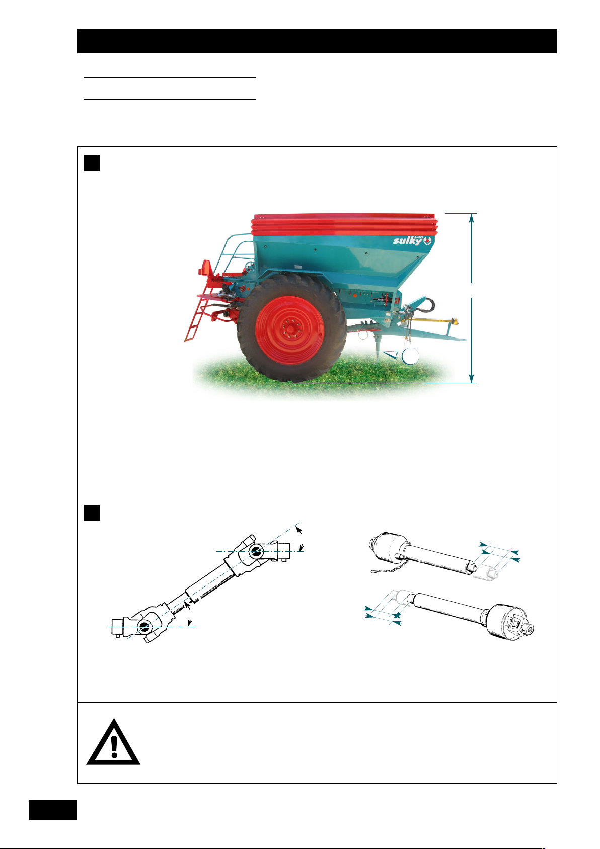
Travailler avec une
transmission protégée en
bon état, conforme aux
normes en vigueur.
Respecter le régime de prise
de force de 540 tr/min.
When working, the PTO drive
assembly guards must be
fitted and in good condition,
and meet applicable
standards.
Do not exceed a PTO speed
of 540 rpm.
Stets mit einer geschützten
und voll funktionsfähigen
Antriebswelle nach den
geltenden Standards
arbeiten.
Zapfwellendrehzahl von 540
U/min beachten.
B
35°
35°
//
C
1
Page 16

Ankopplung
Maschine mit der Stütze ➀ an den Schlepper ankuppeln
(untere Ankupplung) und Ausleger in der Höhe so
einstellen, dass der obere Fahrgestellrand sich so weit wie
möglich in horizontaler Lage befindet; dies entspricht der
optimalen Arbeitsposition der Scheiben.
Beim An- oder Abkoppeln darauf achten, dass die
Verriegelungsachse der Stütze richtig verriegelt ist.
Zapfwelle
Die Zapfwellendrehzahl beträgt 540 U/min.
Kardanwelle an die Zapfwelle des Schleppers ankoppeln
und Länge prüfen.
(den auf dem Zapfwellenschutz angebrachten
Herstelleranweisungen folgen).
Empfohlene Gelenkwelle verwenden
(siehe technische Eigenschaften).
Ohne diese Vorsichtsmaßnahmen könnte der
Mechanismus beschädigt werden; diesen Schaden würde
die Garantie nicht übernehmen.
Hydraulikanschlüsse an den Schlepper anschließen und
Hydraulikbremsung prüfen.
Sicherheitskabel am Parkbremsenhebel an einen soliden
Verankerungspunkt hinten am Schlepper anhängen. Das
Kabel muss beim Einschlagen der SchlepperMaschinenkombination zugfrei bleiben.
Elektrischen Beleuchtungsstecker anschließen.
Hitching
Hitch the machine to the tractor using parking stand ➀
(low hitch) and adjust the drawbar height until the top
edge of the box is as close as possible to horizontal, i.e.
the most efficient disc working position.
During the hitching and unhitching operations, check that
the stand locking pin is correctly locked.
Power take-off
The speed is 540 rpm.
Connect the universal joint shaft to the tractor PTO,
making sure that it is the correct length
(as indicated by the manufacturer’s notice attached to the
guard).
Use the recommended shaft
(see the Technical Specifications).
Failure to follow these precautions may result in
mechanical damage which would not be covered by the
warranty.
Connect the oil valve to the tractor and check the
hydraulic braking system.
Attach the parking brake safety cable to a sturdy bearing
point behind the tractor. The cable should remain slack
while the tractor/machine assembly is turning.
Connect the electrical lighting socket.
15
FR
GB
DE
Attelage
Atteler la machine au tracteur au moyen de la béquille ➀
(attelage bas) et régler la flèche à une hauteur telle que le
bord supérieur de la caisse soit le plus proche de
l’horizontale, ce qui correspond à la position optimale de
travail des disques.
Pendant les opérations d’attelage, ou de dételage, veiller à
ce que l’axe de verrouillage de la béquille soit
correctement verrouillé.
Prise de force
Le régime est de 540 tr/min.
Raccorder à la prise de force du tracteur la transmission à
cardan en vérifiant sa longueur
(comme l’indique la notice du fabricant fixée sur la
protection).
Utiliser la transmission recommandée
(voir Caractéristiques Techniques).
L’inobservation de cette précaution entraînerait des
dommages au mécanisme qui ne seraient pas couverts
par la garantie.
Raccorder les prises d’huile au tracteur et vérifier le
freinage hydraulique.
Accrocher le câble de sécurité situé sur le levier de frein
de stationnement à un point d’ancrage solide à l’arrière du
tracteur. Le câble doit resté détendu lors du braquage de
l’ensemble tracteur/machine.
Mise en route
Start-up
Inbetriebsetzung
B
C
B
C
B
C
Page 17

“TRAPPE GAUCHE”
“LEFT SHUTTER”
“L
INKER STREUSCHIEBER”
(Réf: 5006 1370)
“V
OIE VARIABLE”
“V
ARIABLE TRACK”
“Ä
NDERUNG SPURWEITE”
(Réf: 5006 1380)
“B
LOCDEDISTRIBUTION”
“D
ISTRIBUTION ASSEMBLY”
“V
ERTEILERBLOCK”
(Réf: 5006 1420)
“E
MBRAYAGE”
“CLUTCH”
“K
UPPLUNG”
(Réf: 5006 1320)
“V
IDANGEÀL’ARRÊT”
“EMPTYING WHEN STOPPED”
“HYDRAULIKÖLWECHSEL BEI
STILLSTAND”
(Réf: 5006 1340)
“T
RAPPE DROITE”
“R
IGHT SHUTTER”
“R
ECHTER STREUSCHIEBER”
(Réf: 5006 1360)
R
EPÉRAGE DES FONCTIONS HYDRAULIQUES
I
DENTIFY THE HYDRAULIC FUNCTIONS
M
ARKIERUNG DER HYDRAULISCHENFUNKTIONEN
16
Mise en route
Start-up
Inbetriebsetzung
C
(Réf: 5006 1300)
S
IGNIFICATIONS DES PICTOGRAMMES
D
IAGRAM EXPLANATIONS
- E
RKLÄRUNG DERPIKTOGRAMME
Page 18

17
FR
GB
DE
Raccorder la prise électrique d’éclairage, et les prises
hydrauliques suivant les pictogrammes placés sur la
machine.
Mise en route
Start-up
Inbetriebsetzung
Connect the lights to the electrical socket and the
hydraulic connections using the diagram placed on the
machine.
Elektrischen Beleuchtungsstecker anschließen, und
ebenso die Hydraulikstecker anhand der Piktogramme an
der Maschine anschließen.
Page 19
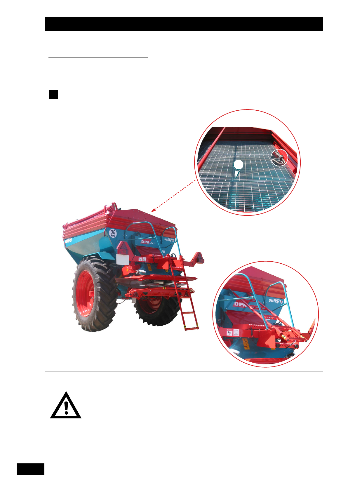
Veillez, lorsque le tracteur
est braqué, et afin d’éviter
toutes détériorations, que les
pneumatiques ne viennent
pas en contact avec
l’épandeur ou certains de
ses composants.
Pendant tous les
déplacements, au travail ou
sur la route, l’échelle doit
être totalement repliée.
When the tractor is turning,
make sure that the tyres do
not touch the spreader or
any spreader parts as this
may cause damage.
For either work or on-road
travelling, the steps must be
completely folded away.
Um Beschädigungen zu
vermeiden muss darauf
geachtet werden, dass die
Reifen beim Einschlagen des
Schleppers nicht mit dem
Streuer oder seinen
Bestandteilen in Berührung
kommen.
Bei der Feldarbeit oder beim
(Straßen)-Transport muss
die Leiter vollständig
hochgeklappt sein.
18
Mise en route
Start-up
Inbetriebsetzung
E
1
Page 20

Bereifung
Einige Maschinen sind für breite Bereifung zugelassen.
In diesem Fall darf das Gesamtaußenmaß der Maschinen
2,25 m überschreiten (bis 3 m sind erlaubt), wenn die
Maßüberschreitung ausschließlich von den Reifen erzeugt
wird. Die eigentlichen Maschinenmaße müssen auf 2,25 m
beschränkt sein.
Beim Straßentransport mit einer Maschine, deren Außenmaß
aufgrund der Bereifung zwischen 2,55 m und 3,00 m liegt,
bedarf es in Frankreich einer Genehmigung durch die
Präfektur.
In diesem Fall die Präfekturverordnungen der Departements
einsehen, in denen die Maschine gefahren werden soll.
Ohne Zulassung und Präfekturgenehmigung ist die
Überschreitung des Gesamtaußenmaßes ausschließlich bei
der eigentlichen Feldarbeit erlaubt.
In allen Fällen nur die in untenstehender Tabelle aufgeführte
Bereifung verwenden.
W
ICHTIG:
Derzeit liegt die maximale Geschwindigkeit auf
öffentlichen Straßen in Frankreich bei 25 km/h.
Kontrollieren, ob der Klumpenschutz an der richtigen
Stelle angebracht ist.
Wenn Ihr Streuer mit Trichteraufbau und Klumpenschutz ➀
ausgestattet ist, auf die Anbringung an der richtigen Stelle
achten, um Beschädigung zu vermeiden.
Tyres
Some machines may be approved for extra-width tyres.
If such tyres are fitted the overall vehicle width can exceed
2.55 m but not 3.00 m, provided that the extra width is only
caused by the tyres and that the rest of the vehicle does not
exceed 2.55 m.
A permit is required to drive on public roads in a vehicle
whose tyres cause the overall width to exceed 2.55 m whilst
remaining within the 3.00 m limit.
Please consult the local laws covering the areas in which the
machine will be driven.
If no approval or authorization exists, the machine may only
be permitted to exceed the stipulated width
during use in the field.
The machine should only ever be fitted with the tyres in the
following table.
I
MPORTANT:
Today, the maximum on-road driving speed in
France is 25 km/h.
Check that the anti-clod screens are in the correct
position.
Make sure that the spreader’s extensions and anti-clod
screen kit
➀, if included, are fitted properly.
T
YRE
T
YRE PRESSURE
T
YRE PRESSURE
T
YPE
COMBINED COMBINED
ROAD
/
FIELD USE ROAD/FIELD USE
25 KM/H(F
RANCE
) 25 KM/H(
OTH ER
)
550/60 - 22,5 12 PR 1,5 bars 1,8 bars
11.2 R44 140 A8 3,6 bars - bars
600/55 - 26,5 12 PR 1,3 bars 1,3 bars
11.2 R48 142 A8 3,2 bars 3,6 bars
18.4 R38 149 A8 1,6 bars 1,4 bars
18.4 R42 148 A8 1,6 bars 1,4 bars
19
FR
GB
DE
Pneumatiques
Certaines machines peuvent être homologuées en autorisant
des montes de pneumatiques de forte largeur.
Dans ce cas la largeur hors-tout des machines peut excéder
2,55m sans dépasser 3,00m à la seule condition que ce
dépassement ne soit causer que par les pneumatiques, le
reste de la machine ne doit pas dépasser 2,55m.
Une circulation sur route avec une machine dont les
pneumatiques dépassent la largeur de 2,55m sans dépasser
3,00m, est soumise à autorisation préfectorale.
Veuillez consulter les arrêtés préfectoraux des départements
dans lesquels la machine va se déplacer.
En l’absence d’homologation et d’autorisation préfectorale,
un dépassement de largeur est autorisé exclusivement
pendant une utilisation aux champs.
Dans tous les cas n’utiliser que les pneumatiques indiqués
dans le tableau ci-dessous.
I
MPORTANT:
Actuellement, la vitesse de circulation maximale
sur route en France est de 25 Km/h.
Contrôler le bon emplacement des grilles anti-motte
Si votre épandeur est équipé de réhausses et d’un jeu de
grilles anti-motte
➀, veillez à ce que celles-ci soient bien
placées afin d’éviter les dommages.
Mise en route
Start-up
Inbetriebsetzung
D
ÉSIGNATION
P
RESSION DE GONFLAGEPRESSION DE GONFLAGE
PNEUMATIQUES
C
IRCU LATION M IXTE
C
IRCU LATION M IXTE
ROUTE
/
CHAMP ROUTE/CHAMP
25 KM/H(F
RANCE
) 25 KM/H(A
UTRE PAYS
)
550/60 - 22,5 12 PR 1,5 bars 1,8 bars
11.2 R44 140 A8 3,6 bars - bars
600/55 - 26,5 12 PR 1,3 bars 1,3 bars
11.2 R48 142 A8 3,2 bars 3,6 bars
18.4 R38 149 A8 1,6 bars 1,4 bars
18.4 R42 148 A8 1,6 bars 1,4 bars
Spécification Fabricants
D
E
D
E
D
Herstellerspezifikation
E
Manufacturers’ specification
B
EZEICHNUNG
R
EIFENDRUCK
R
EIFENDRUCK
B
EREIFUNG
G
EMISCHTFAHREN
G
EMISCHTFAHREN
S
TRAßE
/ F
ELD
S
TRAßE
/ F
ELD
25 KM/H(F
RANCE
)
25KM/H (ANDERE LÄNDER)
550/60 - 22,5 12 PR 1,5 bars 1,8 bars
11.2 R44 140 A8 3,6 bars - bars
600/55 - 26,5 12 PR 1,3 bars 1,3 bars
11.2 R48 142 A8 3,2 bars 3,6 bars
18.4 R38 149 A8 1,6 bars 1,4 bars
18.4 R42 148 A8 1,6 bars 1,4 bars
Page 21
20
Mise en route
Start-up
Inbetriebsetzung
Vous devez vider
complètement la trémie
avant le chargement.
The hopper must be
emptied completely
before it is filled.
Trichter vor dem Füllen
vollständig entleeren.
F
Page 22

21
FR
GB
DE
Chargement de la trémie
Vous devez vider complètement la trémie avant le
chargement.
D
ÉBUT DE L’ÉPANDAGE APRÈS U N NOUVEAU CHARGEMENT:
Si la machine a bien été complètement vidée avant d’être
rechargée, le redémarrage ne pose aucun problème.
Toutefois, un long trajet chargé peut provoquer un tassement
de l’engrais, et un blocage au redémarrage. Dans ce cas, le
blocage se produit dans les 50 cm situés juste avant la
trappe; au redémarrage, la sécurité située sur la transmission
DPA, (limiteur de couple à cames et ressorts) se déclenche.
Il suffit alors de débourrer sur cette longueur (manche de
pelle pour déstabiliser la masse d’engrais bloquée), pour que
la machine reparte normalement.
F
Mise en route
Start-up
Inbetriebsetzung
Loading the hopper
The hopper must be emptied completely before it is filled.
S
PREADING AFTER THE HOPPER HAS BEEN REFI LLED:
The machine will start up again without any problem if it was
completely emptied before being refilled.
Nevertheless, the fertilizer may become compacted during a
long journey, causing a blockage when the machine is
restarted. If a blockage occurs it will be in a 50-cm area just
behind the flaps; the safety system on the DPA shaft (cam
and spring type slip clutch) will be activated when the
machine is restarted. The blockage needs simply to be
removed along this length (use a shovel handle to break up
the fertilizer causing the blockage) to be able to restart the
machine.
F
Füllen des Trichters
Trichter vor dem Füllen vollständig entleeren.
BEGINN DER AUSBRINGUNG NACH DEM FÜLLEN.
Wenn die Maschine vor dem Füllen vollständig geleert
wurde, läuft die Streuung problemlos wieder an.
Eine lange Fahrt mit gefülltem Trichter kann zur Verdichtung
des Streugutes und zur Blockierung beim Anlaufen führen. In
diesem Fall setzt sich das Streugut in den 50 cm oberhalb
der Klappe fest; beim Anlaufen wird die
Sicherheitsvorrichtung auf der DPA-Gelenkwelle
(Nockenreibkupplung mit Federn) ausgelöst. Das Streugut
braucht nur bis in diese Höhe gelockert zu werden (mit dem
Spatenstiel Streugutmasse lockern), dann läuft die Maschine
wieder normal an.
F
Page 23

22
Réglages
Settings
Einstellungen
Avant utilisation, consulter
le manuel d’utilisation et
respecter les règles de
sécurité.
Contrôler régulièrement la
tension du tapis.
Read the user manual and
follow the safety instructions
before use.
Check the tension of the
conveyor belt at regular
intervals.
Vor dem Einsatz
Betriebshandbuch
konsultieren und
Sicherheitsvorschriften
beachten.
Regelmäßig die Spannung
des Förderbandes
kontrollieren
A
Page 24

23
FR
GB
DE
Réglage de la machine
• Poutre d’éclatement
Pour l’épandage de la plupart des produits, la poutre
d’éclatement longitudinale élimine les problèmes de
tassement au chargement et pendant le transport. Elle
supprime les effets de voûte pendant l’extraction. On obtient
ainsi une alimentation constante du produit jusqu’à la
vidange totale de la trémie. La machine assure donc un
épandage régulier de tous types d’engrais granulés.
R
EMARQUE:
Il est possible qu’après plusieurs heures de fonctionnement,
et bien souvent lors de la première mise en service, que le
tapis se détende légèrement. On obtiendra alors un
glissement du tambour d’entraînement sous la bande.
R
EMÈDE:
Tendre le tapis modérément au moyen des 2 paliers
tendeurs, afin d’obtenir une adhérence
suffisante. Pour éviter que le tapis se déporte, ce qui
provoquerait son usure prématurée, il convient de tendre
les 2 paliers tendeurs de manière identique.
Les guides évitent le déplacement du tapis hors des
limites acceptables. Mais ils ne doivent, en aucun cas,
être considérés comme des pièces de frottement
permanent.
Les tambours améliorent le guidage.
Afin d’éviter d’éventuels dommages sur la mécanique,
lors d’un effort violent (par exemple : tambour bloqué par
un corps étranger, etc...) le réducteur supérieur de
l’entraînement est protégé par un limiteur de couple à
cames situé sur la transmission à cardan du DPA.
NB: Ce limiteur doit toujours être taré à un couple
de 260 N.m maximum.
A
Réglages
Settings
Einstellungen
Machine settings
• Breaker arm
The lengthways breaker arm eliminates compaction problems
for most products during loading and transport, and prevents
bridging during extraction, maintaining a smooth flow of
product until the hopper is completely empty. The machine is
therefore able to spread all types of granular fertilizer evenly.
N
B:
The conveyor may slacken slightly after several hours of
operation and especially when it is used for the first time.
This will cause the drive pulley under the belt to lose some
of its grip.
S
OLUTION:
Tension the belt slightly with the 2 take-ups so that it
acquires sufficient grip. To stop the belt from moving out of
true and suffering premature wear, the two take-ups should
both be tensioned the same.
The tracks keep the belt within acceptable limits. They are
not, however, intended to be subject to constant friction.
The pulleys improve belt guidance.
To prevent any mechanical damage due to severe exertion
(e.g. pulley blocked by an irregular object, etc.), a cam type
slip clutch on the DPA universal joint shaft protects the drive.
NB: This slip clutch must always be calibrated to a maximum
torque of 260 N.m.
A
Einstellung der Maschine
• Zerstreuungsvorrichtung
Bei der Ausbringung der meisten Streugutarten beseitigt die
längs liegende Zerstreuungsvorrichtung die beim Beschicken
und durch den Transport entstehende Verdichtung. Die
Vorrichtung verhindert das Entstehen einer kompakten
Streugutmasse während der Ausbringung. Die Speisung des
Streugutes ist so konstant, bis der Trichter vollständig leer ist.
Die Ausbringung aller Düngergranulate ist daher regelmäßig.
A
NMERKUNG:
Es kann vorkommen, dass sich das Förderband nach
mehreren Betriebsstunden und oft bei der ersten
Inbetriebnahme leicht entspannt. Die Antriebstrommel unter
dem Förderband kann dann seitlich ein wenig wegrutschen.
A
BHILFE:
Förderband mit den 2 Spannlagern nur so stark spannen,
dass eine ausreichende Haftung entsteht. Damit das
Förderband nicht seitlich wegrutscht, was zum vorzeitigen
Verschleiß führen würde, müssen beide Spannlager gleich
stark gespannt werden.
Die Führungen verhindern, dass das Band zu weit
wegrutscht. Die Führungen dürfen keinesfalls als ständige
Reibungsteile angesehen werden.
Die Trommeln unterstützen die Führung.
Um mögliche mechanische Schäden zu verhindern bei
starken Belastungen(zum Beispiel: Trommel durch
Fremdkörper blockiert usw.)ist der obere Antriebsregler
durch eine Nockenreibkupplung auf der Kardanwelle des
DPA geschützt.
NB: Diese Nockenreibkupplung ist stets auf ein
Drehmoment von maximal 260 N einzustellen.
A
2
Page 25
24
Réglages
Settings
Einstellungen
Contrôler le débit, un nouvel
étalonnage peut s'avéver
nécessaire suivant les
conditions.
Check the rate of flow as it may
be necessary to re-calibrate to
suit the conditions
Streumenge überwachen, je
nach Verhältnissen kann eine
neue Eichung notwendig sein.
B
a)
b)
3
4
2
1
1
2
3
Page 26

25
FR
GB
DE
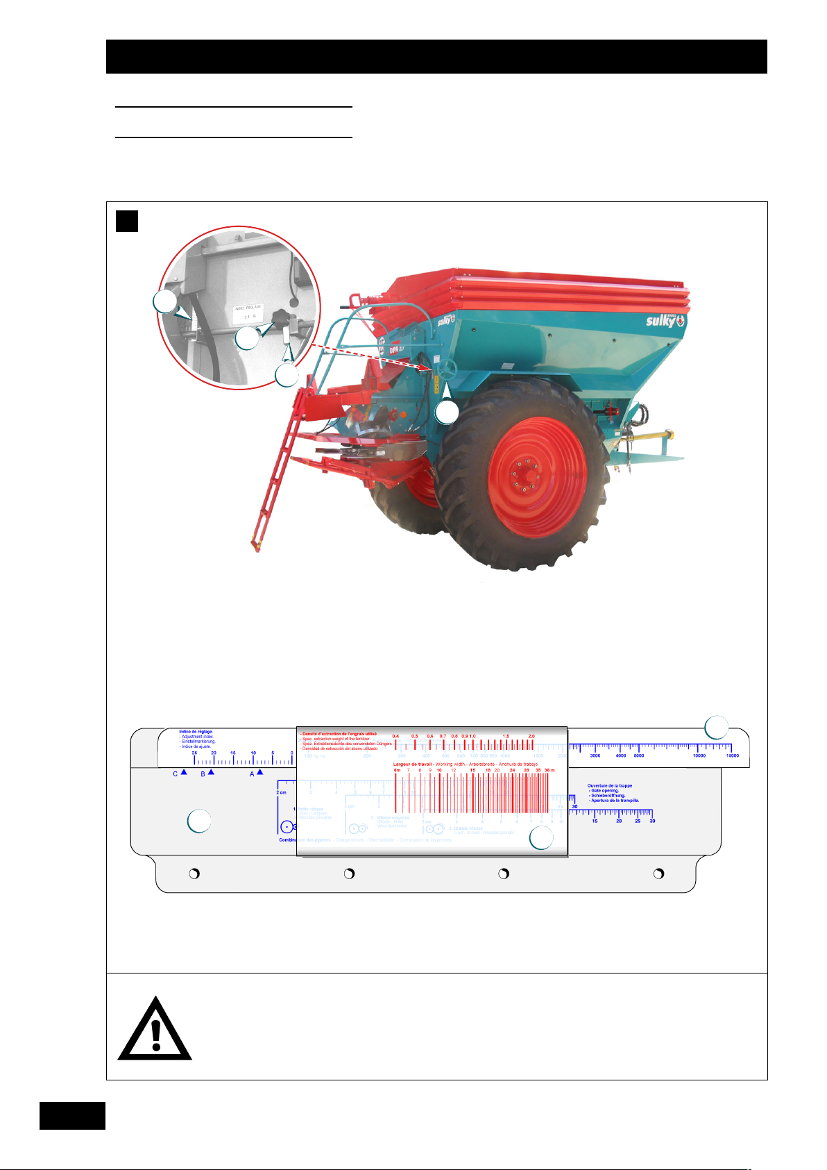
Réglage du débit
a) Réglage
Le DPA-XLT est une machine avec distribution dite
volumétrique.
Le débit est obtenu en jouant sur la hauteur de la trappe
d'ouverture à la sortie du tapis.
- Desserrer le levier inox ➀ et la molette noire ➁.
- Tourner le volant ➂.
- Mettre le repère de réglage donné par la réglette
➃.
Remarque:
Pour les petits débit/ha mettre en position la deuxième
trappe inox (divise le débit par 2).
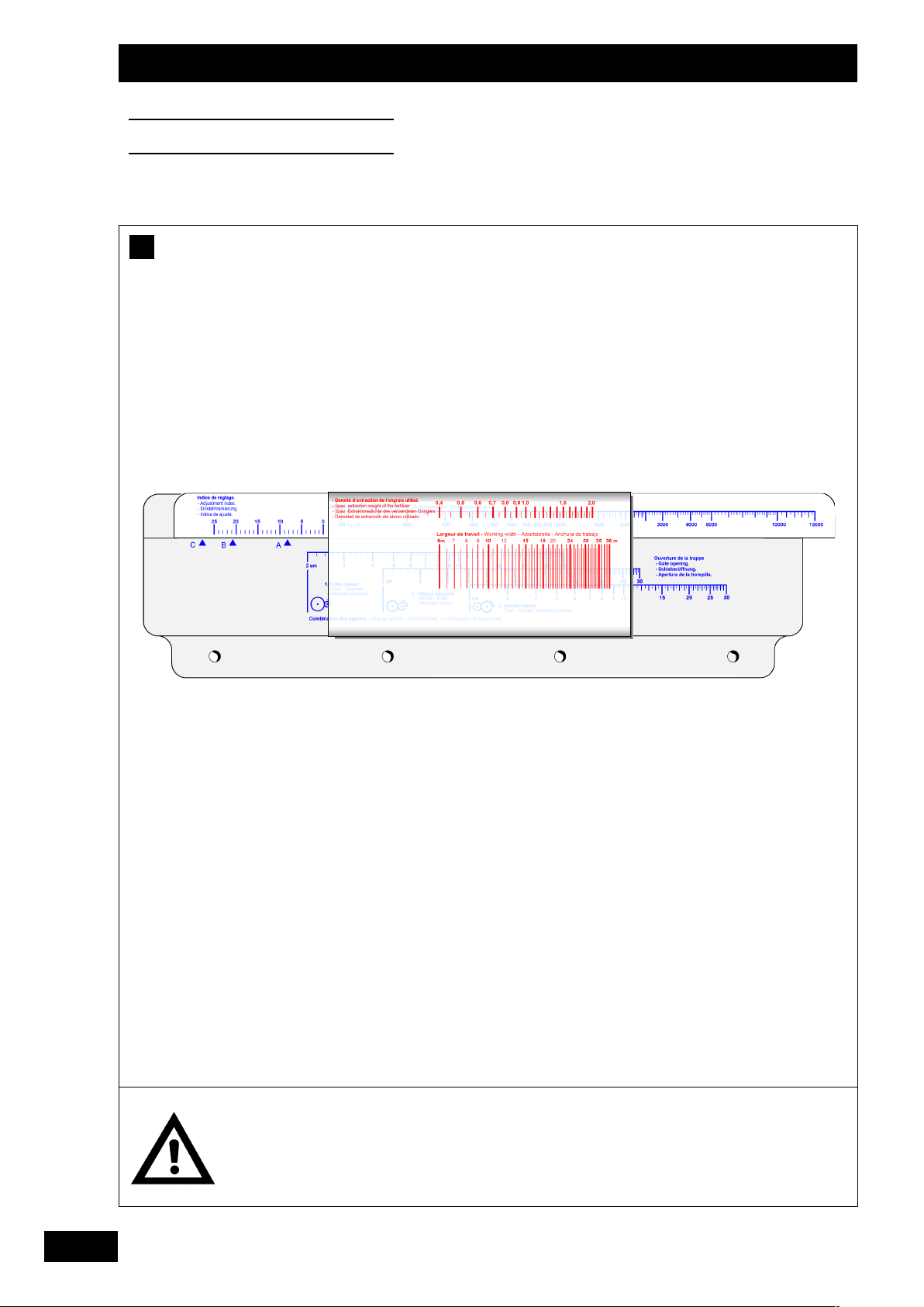
b) Réglette
La réglette de dosage, fournie avec la machine, permet de
lire directement les réglages à utiliser pour obtenir le dosage
désiré, en fonction de la densité et de la largeur de travail.
La densité à prendre en compte pour le réglage est la
densité d’extraction, c’est-à-dire la densité du produit à la
sortie de la trappe.
Des variations peuvent apparaître selon la nature des
produits et certains paramètres extérieurs tels que
l’hygrométrie, la température ambiante ou le tassement. Il
convient donc de contrôler le débit obtenu, et d’étalonner la
réglette en apportant une éventuelle correction par le choix
d’un indice de réglage différent.
Remarque:
Si la quantité de produit épandu est moins importante que
celle désirée, choisir un indice de réglage plus fort
(0
----
>25).
Si la quantité de produit épandu est plus importante que
celle désirée, choisir un indice de réglage plus faible
(25
----
>0).
B
Réglages
Settings
Einstellungen
Adjusting the flow rate
a) Adjustment
The DPA-XLT machine uses a volumetric metering system.
The application rate is set by manipulating the height of
the outlet flap at the end of the belt.
- Unscrew the stainless steel lever ➀ and the black
thumb wheel ➁.
- Turn the hand wheel ➂.
- Set to the mark given by the slide calculator ➃.
NB:
When applying a small rate per hectare, put the second
stainless steel flap into place (application rate divided by 2).
b) Slide calculator
The metering calculator supplied with the machine lets you
see which settings to use in order to apply the required dose
based on the density and the working width.
The density used to determine the setting is the extraction
density, i.e. product density on leaving the flap.
Differences may arise depending on the type of product and
certain external factors such as moisture levels, local
temperature or compaction. The output should therefore be
checked and the slide calculator calibrated by altering the
setting index if necessary.
N
B:
If the product is spread in a lower quantity than required,
select a higher setting index.
(0---->25).
If the product is spread in a higher quantity than required,
select a lower setting ratio
(25---->0).
B
Streumengeneinstellung
a) Einstellung
Der DPA-XLT Streuer hat einen volumetrischen
Streumechanismus.
Die Streumenge ergibt sich aus der eingestellten Höhe
der Klappe am Förderbandausgang.
- Edelstahlhebel ➀ und schwarzes Rädchen ➁ lockern.
- Schwungrad ➂ drehen.
- Durch die Skala ➃ gegebene Einstellmarke einstellen.
Anmerkung:
Bei geringer Streumenge/ ha zweite Edelstahlklappe
verwenden (halbiert die Streumenge).
b) Skala
Über die mit der Maschine gelieferte Dosierungsskala
können die Einstellungen für die gewünschte Dosierung in
Abhängigkeit von der Saatdichte und der Arbeitsbreite direkt
abgelesen werden.
Für die Einstellung zu berücksichtigen ist die AusbringungsSaatdichte, d.h. die Saatdichte am Ausgang der Klappe.
Je nach Saatgut und bestimmten äußeren Parametern wie
Luftfeuchtigkeit, Außentemperatur oder Verdichtung können
Variationen in der Saatdichte auftreten. Die Saatdichte muss
also überwacht und die Skala geeicht werden. Bei Bedarf
können Korrekturen durch Wahl einer anderen
Einstellrichtzahl vorgenommen werden.
A
nmerkung:
Liegt die ausgebrachte Menge unter der gewünschten
Saatdichte, eine höhere Einstellrichtzahl wählen.
(0---->25).
Liegt die ausgebrachte Menge über der gewünschten
Saatdichte, eine geringere Einstellrichtzahl wählen.
(25---->0).
B
Page 27
26
Réglages
Settings
Einstellungen
Contrôler le débit, un nouvel
étalonnage peut s'avéver
nécessaire suivant les
conditions.
Check the rate of flow as it may
be necessary to re-calibrate to
suit the conditions
Streumenge überwachen, je
nach Verhältnissen kann eine
neue Eichung notwendig sein.
B
b)
Page 28

Untenstehende Tabelle zeigt die „Einstellrichtzahlen“ in
Abhängigkeit von der Bereifung. Die Richtzahl der Maschine
wird zur Erinnerung durch einen Aufkleber am hinteren
Maschinenende in der Nähe der Klappe angegeben.
Bei abweichender Bereifung bei uns um Rat fragen.
The table below shows the "setting indices" for the main
types of tyre fitted. The machine index is shown on a sticker
at the rear, near to the flap.
Please contact us regarding other tyres.
27
FR
GB
DE
Le tableau ci-dessous donne les «indices de réglage»
correspondant aux principales montes de pneumatiques.
L’indice de la machine est rappelé par un autocollant situé à
l’arrière, à proximité de la trappe.
Autres pneumatiques nous consulter.
Réglages
Settings
Einstellungen
D
ÉSIGNATION
PNEUMATIQUES
I
NDICE DE RÉGLAGE
550/60 - 22,5 12 PR 8 B
11,2 R 44 140 A8 15 B
600/55 - 26,5 12 PR 10 B
11,2 R 48 142 A8 17 B
18,4 R 38 - 149 A8 17 B
18,4 R 42 - 148 A8 19 B
Spécification Fabricants
T
YRE
TYPE
S
ETTING INDEX
550/60 - 22,5 12 PR 8 B
11,2 R 44 140 A8 15 B
600/55 - 26,5 12 PR 10 B
11,2 R 48 142 A8 17 B
18,4 R 38 - 149 A8 17 B
18,4 R 42 - 148 A8 19 B
Manufacturers’ specification
B
EZEICHNUNG
B
EREIFUNG
E
INSTELLRICHTZAHL
550/60 - 22,5 12 PR 8 B
11,2 R 44 140 A8 15 B
600/55 - 26,5 12 PR 10 B
11,2 R 48 142 A8 17 B
18,4 R 38 - 149 A8 17 B
18,4 R 42 - 148 A8 19 B
Herstellerspezifikation
Page 29
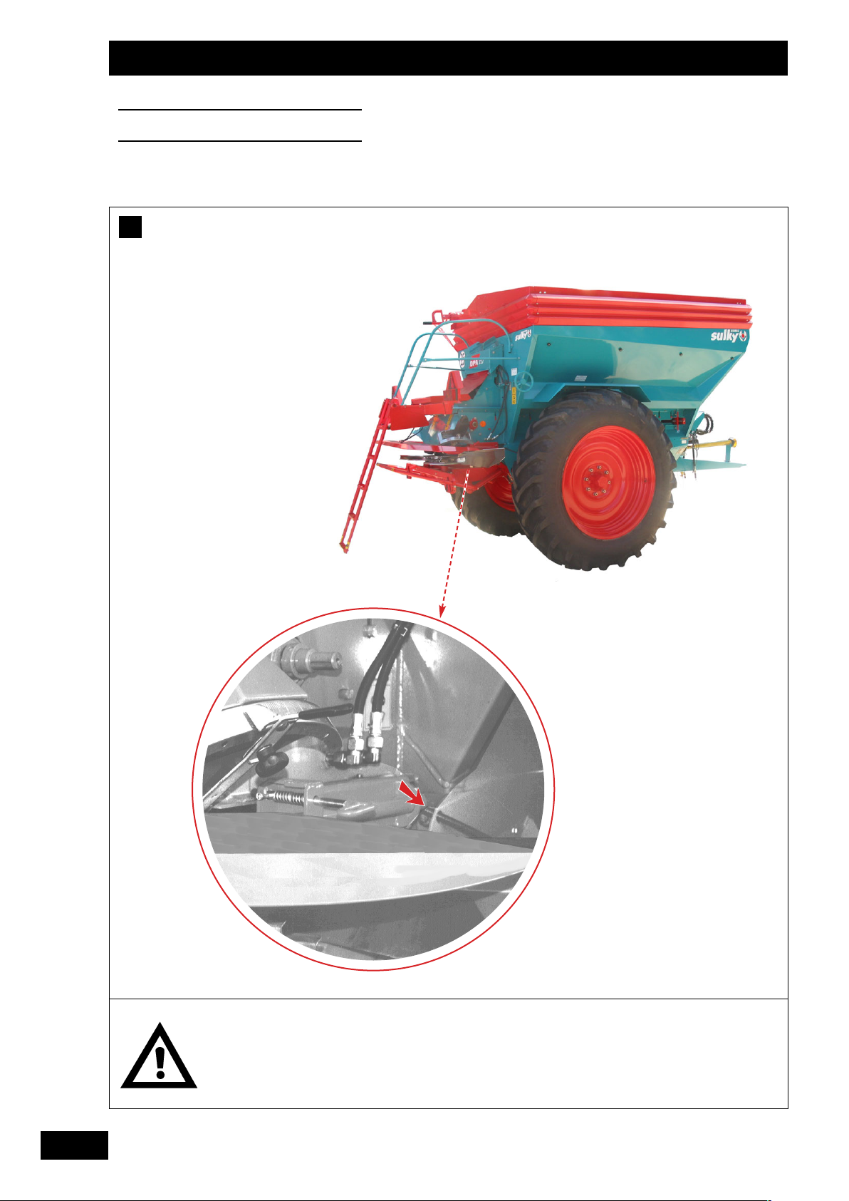
28
Réglages
Settings
Einstellungen
Contrôler le débit, un nouvel
étalonnage peut s'avéver
nécessaire suivant les
conditions.
Check the rate of flow as it may
be necessary to re-calibrate to
suit the conditions.
Streumenge überwachen, je
nach Verhältnissen kann eine
neue Eichung notwendig sein.
B
Page 30

29
FR
GB
DE
c) Essai de débit
Il est possible d'effectuer un essai de débit pour valider
son réglage.
La nature des engrais est tellement variée, qu'il est
recommandé de l'exécuter
Réalisation de l'essai
- Baisser le bloc double plateaux
- Mettre l'arceau de maintient des bacs et bien serrer.
- Mettre les 2 bacs.
- Mettre le repère d'ouverture donné par la réglette.
- Jalonner la distance d'essai à réaliser suivant votre
largeur de travail
12 m . . . . . . . . . . . . . . . . . . . . . . 41,7 m
15 m . . . . . . . . . . . . . . . . . . . . . . 33,4 m
18 m . . . . . . . . . . . . . . . . . . . . . . 27,8 m
20 m . . . . . . . . . . . . . . . . . . . . . . 25,0 m
21 m . . . . . . . . . . . . . . . . . . . . . . 23,8 m
24 m . . . . . . . . . . . . . . . . . . . . . . 20,8 m
27 m . . . . . . . . . . . . . . . . . . . . . . 18,5 m
28 m . . . . . . . . . . . . . . . . . . . . . . 17,9 m
32 m . . . . . . . . . . . . . . . . . . . . . . 15,7 m
36 m . . . . . . . . . . . . . . . . . . . . . . 13,9 m
38 m . . . . . . . . . . . . . . . . . . . . . . 13,2 m
40 m . . . . . . . . . . . . . . . . . . . . . . 12,5 m
42 m . . . . . . . . . . . . . . . . . . . . . . 11,90 m
44 m . . . . . . . . . . . . . . . . . . . . . . 11,36 m
- Bien amorcer la distribution en récupérant (sans peser)
une quantité d'engrais.
(ou après quelques mètres d'épandage)
- Mettre le tracteur au 1erJalon et enclencher le DPA
(ne pas mettre la PDF).
- Rouler jusqu'au 2
ème
jalon et stopper.
- Peser la quantité des 2 seaux et multiplier par 20, vous
obtiendrez la dose /ha.
- Corriger en plus ou en moins si nécessaire l'ouverture
de la trappe.
Réglages
Settings
Einstellungen
c) Calibration test
A calibration test can be performed to confirm that the
correct setting has been applied.
As the fertilizer types vary so greatly a calibration test is
recommended.
Performing the calibration test
- Lower the twin disc unit
- Fit the bucket retaining bar and tighten.
- Fit the 2 buckets.
- Set to the opening mark given by the slide calculator.
- Mark out the test distance according to your working
width
12 m . . . . . . . . . . . . . . . . . . . . . . 41.7 m
15 m . . . . . . . . . . . . . . . . . . . . . . 33.4 m
18 m . . . . . . . . . . . . . . . . . . . . . . 27.8 m
20 m . . . . . . . . . . . . . . . . . . . . . . 25.0 m
21 m . . . . . . . . . . . . . . . . . . . . . . 23.8 m
24 m . . . . . . . . . . . . . . . . . . . . . . 20.8 m
27 m . . . . . . . . . . . . . . . . . . . . . . 18.5 m
28 m . . . . . . . . . . . . . . . . . . . . . . 17.9 m
32 m . . . . . . . . . . . . . . . . . . . . . . 15.7 m
36 m . . . . . . . . . . . . . . . . . . . . . . 13.9 m
38 m . . . . . . . . . . . . . . . . . . . . . . 13.2 m
40 m . . . . . . . . . . . . . . . . . . . . . . 12,5 m
42 m . . . . . . . . . . . . . . . . . . . . . . 11,90 m
44 m . . . . . . . . . . . . . . . . . . . . . . 11,36 m
- Start the flow of fertilizer and retrieve a quantity without
weighing
(or after having spread for a few metres)
- Position the tractor at the 1st marker and engage the
DPA (do not start the PTO).
- Advance as far as the 2nd marker and stop.
- Weigh the contents of both buckets and multiply by 20
to obtain the dose per hectare.
- Adjust the flap opening if necessary.
c) A
bdrehprobe
Zur Überprüfung der Einstellung ist es möglich, eine
Abdrehprobe durchzuführen.
Da die Eigenschaften der Saatarten sehr unterschiedlich
sind, ist eine Abdrehprobe empfehlenswert.
Durchführung der Abdrehprobe
- Verteilerblock mit Doppelstreuscheibe absenken
- Haltebügel der Gitterkästen einsetzen und gut anziehen.
- Beide Gitterkästen einsetzen.
- Von der Skala gegebene Öffnungsmarke einstellen.
- Versuchsabstand je nach Arbeitsbreite abfahren und
markieren
12 m . . . . . . . . . . . . . . . . . . . . . . 41,7 m
15 m . . . . . . . . . . . . . . . . . . . . . . 33,4 m
18 m . . . . . . . . . . . . . . . . . . . . . . 27,8 m
20 m . . . . . . . . . . . . . . . . . . . . . . 25,0 m
21 m . . . . . . . . . . . . . . . . . . . . . . 23,8 m
24 m . . . . . . . . . . . . . . . . . . . . . . 20,8 m
27 m . . . . . . . . . . . . . . . . . . . . . . 18,5 m
28 m . . . . . . . . . . . . . . . . . . . . . . 17,9 m
32 m . . . . . . . . . . . . . . . . . . . . . . 15,7 m
36 m . . . . . . . . . . . . . . . . . . . . . . 13,9 m
38 m . . . . . . . . . . . . . . . . . . . . . . 13,2 m
40 m . . . . . . . . . . . . . . . . . . . . . . 12,5 m
42 m . . . . . . . . . . . . . . . . . . . . . . 11,90 m
44 m . . . . . . . . . . . . . . . . . . . . . . 11,36 m
- Streumechanismus anlaufen lassen und Saatgutmenge
(ohne wiegen) auffangen.
(oder nach einigen Ausbringungsmetern)
- Schlepper an die erste Markierung platzieren und DPA
auslösen (PDF nicht einstellen).
- Bis zur zweiten Markierung vorfahren und anhalten.
- Menge in beiden Eimern abwiegen und mit 20
multiplizieren, der Wert entspricht der Hektardosierung.
- Klappenöffnung bei Bedarf korrigieren (vergrößern oder
verkleinern).
Page 31

30
Réglages
Settings
Einstellungen
Lorsque la dose choisie
impose une ouverture de
trappe supérieure à 18 cm, il
est possible qu’avec certains
engrais, lorsque la trémie est
presque vide, que la trappe
ne soit pas complètement
alimentée jusqu’à la fin. Ne
pas épandre dans ces
conditions, mais recharger à
nouveau la trémie dès que
cela devient nécessaire.
If the selected dose requires
a flap to be opened more than
18 cm the flow of certain
fertilizers to the flap may be
reduced when the hopper is
almost empty. You should not
spread in such a case, but
refill the hopper as soon as
necessary.
Erfordert die gewünschte
Dosierung eine
Klappenöffnung von über 18
cm, kann es bei fast leerem
Trichter vorkommen, dass mit
bestimmten Düngern die
Klappe bis zur vollständigen
Leerung nicht voll gespeist
wird. Unter diesen
Bedingungen nicht weiter
ausbringen, Trichter bei
Bedarf vorzeitig neu auffüllen.
a)
b)
c)
B
1
2
3
1
2
1
3
1
2
3
2
3
Page 32

31
FR
GB
DE
EXEMPLE :
Votre épandeur est un DPA-XLT avec des pneumatiques
11,2 R44****.
Le tableau vous donne comme indice de réglage : 15 B.
Sur votre réglette, positionner l’indice de réglage 15 en face
du repère B. Déterminer alors le réglage de l’appareil à l’aide
du curseur, en prenant bien garde de maintenir les deux
parties de la réglette dans la même position relative.
L’ouverture de la trappe se lit directement sur le réglet,
située du côté droit de la trappe. L’ouverture donnée par la
réglette ou le tableau doit être mesurée entre le fond du
tapis et le bord inférieur de la trappe.
A
TTENTION
La réglette de dosage est une réglette polyvalente. Elle est
utilisée également pour des appareils qui comportent
plusieurs combinaisons possibles de pignons, ce qui
expliquent les 3 vitesses qui y sont notées.
Cependant, les épandeurs DPA-XLT ont une vitesse unique
qui correspond à la vitesse moyenne. Vous devez lire sur la
réglette uniquement l’échelle correspondant à la vitesse
moyenne.
Ex
emple :
DPA-XLT (indice de réglage 15 B)
Epandage à 600 kg d’un engrais de densité 1,25 sur une
largeur de travail de 24m :
Il faut lire sur l’échelle correspondant à la vitesse moyenne et
ouvrir la trappe de 7,6 cm.
Réglages
Settings
Einstellungen
EXAMPLE:
If your spreader is type DPA-XLT fitted with 11.2 R44****
tyres.
The setting index shown in the table is: 15 B.
Move the setting index 15 so that it is lined up with mark B
on your slide calculator. Then use the pointer to ascertain the
machine setting, taking care to keep both parts of the
calculator in the same relative position.
Take the reading for the flap opening directly from the ruler
located on the RH side of the flap. The opening indicated by
the slide calculator or in the table must be measured
between the end of the belt and the lower edge of the flap.
IMPORTANT
The metering slide calculator has many uses. It can also be
applied to machines with several possible gear combinations,
which is why it shows three speeds.
However, DPA-XLT spreaders have one speed (medium).
Readings from the slide calculator must only be taken using
the medium-speed scale.
E
XAMPLE:
DPA-XLT (setting index 15 B)
600 kg of 1.25 density fertilizer spread over a working width
of 24 metres:
The reading should be taken from the medium-speed scale
and the flap opened by 7,6 cm.
B
EISPIEL:
Ihr Streuer ist ein DPA-XLT mit 11,2 R44**** Bereifung.
Die Tabelle gibt als Einstellrichtzahl an: 15 B.
Auf der Skala Einstellrichtzahl 15 gegenüber der B-Marke
stellen. Dann Einstellung des Gerätes mit Hilfe des Zeigers
bestimmen, wobei darauf zu achten ist, dass die beiden Teile
der Skala in der gleichen relativen Position zueinander
bleiben.
Die Klappenöffnung ist rechts von der Klappe direkt von der
Skala ablesbar. Die von der Skala bzw. auf der Tabelle
angegebene Öffnung muss zwischen Bandunterseite und
unterem Klappenrand gemessen werden.
A
CHTUNG
Die Dosierungsskala ist für mehrere Zwecke einsetzbar. Sie
wird ebenfalls für Geräte benutzt, die verschiedene mögliche
Zahnradkombinationen umfassen, daher sind 3
Geschwindigkeiten markiert.
Die DPA-XLT Streuer haben eine einzige Geschwindigkeit,
die der mittleren Geschwindigkeit entspricht. Auf der Skala
nur die Gradeinteilung für die mittlere Geschwindigkeit
ablesen.
B
EISPIEL:
DPA-XLT (Einstellrichtzahl 15 B)
Hektardosierung von 600 kg eines Düngers mit Dichte 1,25
auf einer Arbeitsbreite von 24 m:
Auf der Gradeinteilung für mittlere Geschwindigkeit ablesen:
Klappenöffnung 7,6 cm.
Page 33

32
C
Pour un bon épandage, il
est indispensable de
maintenir les plateaux et
les pales d’éjection en bon
état.
The spreading discs and
blades must be kept in
good condition to ensure
good spreading quality.
Eine präzise Ausbringung
ist nur möglich, wenn
Streuscheiben und
Wurfschaufeln in gutem
Zustand erhalten werden.
Réglages
Settings
Einstellungen
1
Page 34

33
FR
GB
DE
Réglage largeur
a) Utilisation
La goulotte de réglage permet de changer le point de chute
de l’engrais sur le disque et donc de modifier la largeur de travail.
Ce réglage est continu et vous permet quel que soit l’engrais
granulé de trouver le réglage en ayant un recouvrement
optimum. La lecture se fait sur la partie la plus large du repère ➀.
Réglages
Settings
Einstellungen
C
Width adjustment
a) Instructions
The adjusting chute lets you change the point at which the
fertilizer drops onto the disc and so alter the working width.
The setting is continuous and can be used to find the setting
that gives optimum coverage. The reading should be taken
from the widest point of the marker
➀.
C
Einstellungen Arbeitsbreiten
a) Anwendung
Aufgrund der einstellbaren Zuführorgane kann der DüngerAufgabepunkt auf den Teller und damit die Arbeitsbreite
geändert werden. Die Einstellung ist stufenlos, so dass für jede
Düngersorte die Einstellung mit der optimalen Überlappung
gefunden werden kann. Das Ablesen erfolgt auf der breiteren
Seite der Marke ➀.
C
Page 35

34
Réglages
Settings
Einstellungen
➜
➜
E
D
C
B
A
➜
E
D
C
B
A
+
+
E
DC
BA
E
DC
BA
E
DC
BA
1
2
3
1
2
3
10cm
E
C
B
DA
3,15
2,5
2
4
➠
➠
➠
➠
Page 36

35
FR
GB
DE
Réglages
Settings
Einstellungen
b) Caractéristiques de l'engrais
Pour obtenir une grande largeur de travail, la structure et la
forme de l'engrais sont importantes et il est préférable de
choisir le produit le mieux adapté.
Utilisation du granulomètre
1) Positionner le couvercle ouvert. Remplir d'engrais le
compartiment gauche du granulomètre puis refermer
le couvercle.
2) Agiter l'appareil pendant au minimum 10 secondes.
3) L'appareil reposé, lire directement l'histogramme formé
par les cinq colonnes de produits séparés par les tamis.
Les compartiments sont les suivants:
A : de 2mm
B : - de 2,5 à 2mm
C : de 3,15 à 2,5mm
D : de 4 à 3,15mm
E : + de 4mm
Lecture du résultat
• Pour atteindre les performances maximales du
distributeur (44m avec jeu de pales 36-44m par exemple):
80% de l'engrais doit avoir une granulométrie supérieure
à 3mm avec une densité supérieure ou égale à 0,9.
C'est à dire avec le granulomètre
➀ C + D + E ≈ 8cm.
Remarques: Pour l'urée, le chlorure de potasse et tous
les compactés en général :
Pale 12-18m ➪ Largeur maxi 18m
Pale 18-28m
➪ Largeur maxi 24m
Pale 28-36m
➪ Largeur maxi 28m
Pale 36-44m
➪ Largeur maxi 36m
• Engrais homogène ➁
Les granulés se répartissent dans les 2 compartiments
centraux du Granulomètre aucune particule n'est
présente dans les cases extrêmes. Il y a 0% de granulés
de diamètre inférieur à 2mm.
• Engrais hétérogène ➂
Les granulés se répartissent dans 3 ou 4 compartiments.
Il y a une grosse quantité de particules de diamètre
inférieur à 2mm.
b) Düngereigenschaften
Bei großer Arbeitsbreite sind Struktur und Form des Düngers
von Bedeutung, und es ist vorzuziehen, das am besten
geeignete Produkt zu wählen.
Gebrauch des Granulometers
1) Deckel öffnen. Linkes Fach des Granulometers mit
Dünger füllen und Deckel schließen.
2) Gerät mindestens 10 Sekunden lang schütteln.
3) Gerät abstellen, direkt in den fünf durch Siebe
getrennten Säulen die Düngermengen ablesen.
Die Fächer entsprechen folgenden Korngrößen:
A: bis 2mm
B : -2,5 bis 2mm
C : 3,15 bis 2,5mm
D : 4 bis 3,15mm
E : über 4mm
Ablesen des Ergebnisses
• Zum Erzielen maximaler Leistungen des Streuers (z. B.
44 m mit Schaufel- Spiel 36 - 44 m):
80% des Düngers müssen eine Korngröße von mehr als
3 mm mit einer Dichte von mehr oder gleich 0,9
aufweisen.
Bzw. mit dem Korngrößenmesser
➀ C+D+E = 8 cm
Anmerkung. Für Harnstoff, Kaliumchlorid und allgemein
alle verdichteten Produkte:
Schaufel -12-18 m ➪ maxi. Breite 18 m
Schaufel -18-28 m ➪ maxi. Breite 24 m
Schaufel -28-36 m
➪ maxi. Breite 28 m
Schaufel -36-44 m ➪ maxi. Breite 36 m
• Homogener Dünger ➁
Die Granulate verteilen sich in den 2 zentralen
Abteilungen des Korngrößenmessers, aber nicht in den
äußeren Abteilungen. Von den Granulaten haben 0%
einen Durchmesser von weniger als 2 mm.
• Heterogener Dünger
➂
Die Granulate verteilen sich in 3 oder 4 Unterteilungen.
Eine große Menge der Teilchen haben einen Durchmesser
von weniger als 2 mm.
b) Fertilizer properties
The structure and form of the fertilizer are important factors
in acquiring a large working width, and the most suitable
product should be used.
Using the granulometer
1) Open the cover. Fill the LH compartment with fertilizer
and close the cover.
2) Shake the granulometer for at least 10 seconds.
3) Set the granulometer down to see how the mesh
screens have separated the products into five columns.
The compartment sizes are as follows:
A: < 2 mm
B : 2,5 to 2 mm
C : 3.15 to 2.5 mm
D : 4 to 3.15 mm
E : > 4 mm
Reading the result
• To achieve maximum performance with your spreader
(44 m with a 36-44 m set of blades, for example):
80% of the fertilizer granules must be larger than
3 mm and a density at least equal to 0.9; i.e. with
granulometer
➀, C+D+E ≈ 8 cm
Note: With urea, potassium chloride and all compact
fertilizers in general:
12-18 m blade ➪ max. width of 18 m
18-28 m blade ➪ max. width of 24 m
28-36 m blade
➪ max. width of 28 m
36-44 m blade
➪ max. width of 36 m
• Homogeneous fertilizer
➁
The granules are concentrated in the two central
compartments of the Granulometer with no particles in
the outer compartments. No granules are less than
2 mm in diameter.
• Heterogeneous fertilizer ➂
Granules are found in three or four compartments. A
large quantity of particles are less than 2 mm in diameter.
Page 37

36
Pour un bon épandage, il
est indispensable de
maintenir les plateaux et
les pales d’éjection en bon
état.
To ensure good spreading
quality, the discs and
blades must be kept in
good condition.
Eine präzise Ausbringung
ist nur möglich, wenn
Streuscheiben und
Wurfschaufeln in gutem
Zustand erhalten werden.
Réglages
Settings
Einstellungen
540tr/mn
c)
Granulométrie
Fertilizer granulometry
Korngrössenbestimmung
Type
Typ
KALI
PATEN T
KALI
PHOSPHAT
10-22-65
K
ALI 60 ER
GRAN 60 %
K S
ALZ
GMBH
KALKSALPETER
15,5 % N
KEMIRA
14-10-24
Info
12 130
112233
15 133
112244
18 137 125
21 128
110022
24 131
110055
28 135 112
110077
32 -
111100
36 - 117
40 44 12 133
112266
15 135
112277
18 138 128
21 131
112233
24 133
112255
28 136 128
112288
32 130
113300
36 - 133
40 135
44 12 110
15 115
110088
18 112
21 116
110011
24 121
110066
28 113
111111
32 -
111177
36 - 123
40 44 12 131
112233
15 133
112255
18 135 127
21 129
112200
24 131
112244
28 133 126
112255
32 128
112299
36 130 131
40 133
44 135
12 120
110022
15 126
110055
18 132 110
21 113
111111
24 118
111122
28 123 115
111166
32 121
111177
36 127 12 0
40 126
44 132
d 1
d 1,1
d 1,06
d 1,1
d 1,04
1812
2818
3628
4436
36
28
115
115
TType
ype
TTyp
yp
K
K
EEMMIIRRA
A
14-10-2
14-10-244
228
8
Page 38

37
FR
GB
DE
c) Réglage
• Réglage avec tableaux
En consultant les tableaux, rechercher l’engrais qui se
rapproche le plus du produit que vous avez à épandre
suivant ses principales caractéristiques, à savoir : sa
grosseur, sa densité, sa forme et sa rugosité.
Mettre la goulotte au repère lu et serrer la molette.
Ex: K
EMIRA
Jeu de pale 28-36 à 28m > repère 115
Pour obtenir une grande largeur de travail, la structure et
la forme de l'engrais sont importantes, et il est
préférable de choisir le produit le mieux adapté.
Réglages
Settings
Einstellungen
c) Einstellung
• Einstellung anhand der Tabelle
In den Tabellen durch Beachten der folgenden
Eigenschaften den Dünger auswählen, der Ihrem
Düngerprodukt am nächsten ist: Korngröße, Dichte, Form
und Rauhigkeit.
Zufuhrorgane auf die abgelesene Marke stellen und
Rädchen anziehen.
Bsp.: Neuer „K
EMIRA“
Streuschaufelsatz 28-36 bei 28m > Marke 115
Bei großer Arbeitsbreite sind Struktur und Form des
Düngers von Bedeutung, und es ist vorzuziehen, das am
besten geeignete Produkt zu wählen.
c) Settings
• Setting using tables
When consulting the tables, look for the fertilizers whose
properties most closely resemble the product you will be
spreading, i.e. its size, density, shape and coarseness.
Set the chute to the appropriate mark and tighten the
thumb wheel.
E.g New “K
EMIRA”
28-36 blade set at 28 metres > mark 115
The structure and shape of the fertilizer are important
factors in obtaining a large working width, and so the
most suitable product should be chosen.
Page 39

38
Réglages
Settings
Einstellungen
A
B
C
D
D
E
E
E
1
2
4
3
A
C
B
E
D
3,15
2,5
2
4
C
1
Page 40

39
FR
GB
DE
Contrôle largeur
• Réglage avec essais de recroisement
La zone critique d’épandage correspond au
recouvrement entre un aller-retour du distributeur. Le kit
permet de contrôler cette zone vous permettant ainsi
d’ajuster le réglage.
• Mise en place de l’essai :
➀ Préparer les bacs, monter les cloisons et les poser
dans chaque bac.
Réglages
Settings
Einstellungen
Grenzstreung Einstellung
• Einstellung mit Überlappungsprobe
Die kritische Streuzone entspricht der Überlappung
zwischen einer Hin- und Rückfahrt des Streuers. Die
Ausrüstung erlaubt die Kontrolle dieser Zone und damit
die Feineinstellung.
• Anbringen des Probe-Sets
:
➀ Die Mulden vorbereiten, die Trennwände montieren
und sie in jeder Mulde anbringen.
Checks width
• Setting with overlapping tests
The critical spreading zone corresponds to the coverage
between an outward and return pass. The kit enables
this zone to be checked to enable you to adjust the
setting.
• Setting up the test:
➀ Prepare the bins, mount the partitions and fit them
into each bin.
Page 41

40
Réglages
Settings
Einstellungen
Pour un bon épandage, il
est indispensable de
maintenir les plateaux et
les pales d’éjection en bon
état.
For correct spreading, the
discs and the ejector
blades need to be kept in
good condition.
Streuscheiben und
Wurfschaufeln müssen für
ein gutes Streuergebnis in
gutem Zustand sein.
1,10m 2,20m 3,30m 4,50m
1,25m 2,50m 3,75m 5,00m
1,50m 3,00m 4,50m 6,00m
1,80m 3,70m 5,60m 7,50m
2,00m 4,00m 6,00m 8,00m
2,25m 4,50m 6,75m 9,00m
2,50m 5,00m 7,50m 10,00m
2,60m 5,20m 7,80m 10,50m
3,00m 6,00m 9,00m 12,00m
3,38m 6,76m 10,14m 13,50m
3,50m 7,00m 10,50m 14,00m
4,00m 8,00m 12,00m 16,00m
4,50m 9,00m 13,50m 18,00m
4,75m 9,50m 14,25m 19,00m
5,00m 10,00m 15,00m 20,00m
5,25m 10,50m 15,75m 21,00m
5,50m 11,00m 16,50m 22,00m
99mm
1100mm
1122mm
1155mm
1166mm
1188mm
2200mm
2211mm
2244mm
2277mm
2288mm
3322mm
3366mm
3388mm
4400mm
4422mm
4444mm
1/2 L
=
1234
L
C
2
Page 42

41
FR
GB
DE
➁ Anbringen der Mulden:
- Ihre empfohlene Stellung je nach Arbeitsbrfeite und
benutztem DPA XLT-Modell einhalten (gemäß Tabelle
2)
- Sie auf flachem Boden aufstellten.
➁ Positioning the bins:
- Make sure their position is correct in consideration of
your working width and the type of your DPA XLT
(see table 2)
- Place them on level ground.
➁ Placement des bacs :
- Bien respecter leurs positions en fonction de votre
largeur de travail et de votre DPA XLT (suivant le
tableau 2)
- Les placer sur un sol plat.
Réglages
Settings
Einstellungen
Page 43

42
Réglages
Settings
Einstellungen
15m
50m
15m
50m
L
1/2
120m
C
3
2
1
Page 44

43
FR
GB
DE
• Réalisation de l'essai
La distance d’essai nécessaire est d’environ 120 m.
➀ Mettre en route l’épandeur une dizaine de mètres
avant les bacs.
➁ Ne stopper la distribution que 50 m au minimum après
avoir passé les bacs.
➂ Reprendre le passage correspondant à votre largeur de
travail.
Réglages
Settings
Einstellungen
• Durchführung der Probe
Die notwendige Probeentfernung beträgt ca. 120 m.
➀ Streuer etwa zehn Meter vor den Mulden anstellten.
➁ Die Verteilung erst 50 m hinter den Mulden stoppen.
➂ Die Ihrer Arbeitsbreite entsprechende Fahrt
wiederaufnehmen.
• The test itself
The distance required for the test is around 120 m.
➀ Start up the spreader about ten metres before the bins.
➁ Only stop spreading after passing the bins by at least
50 m.
➂ Make another pass corresponding to your working
width.
Page 45

44
Réglages
Settings
Einstellungen
➪
+ 50%
+ 25%
➪
+ 10%
+10
➪
+ 50%
+ 5
➪
+ 25%
+ 2
➪
+ 10%
-10
- 30%
OK
OK
- 5
➪
- 2
C
a
b
1
2
3
4
Page 46

45
FR
GB
DE
• Analyse de l'essai
➀ Quantité identique dans les 4 éprouvettes:
☞ Bon recroisement correspondant à un bon
épandage.
➁ Trop d’engrais au recroisement:
☞ Réglage de la goulotte trop important.
• Diminuer le réglage de la goulotte en fonction de
la surdose mesurée au recroisement.
EXEMPLE: Pour un sur-dosage au recroisement de l’ordre de
25%, diminuer la goulotte de 5.
Pour des sur-dosages intermédiaires, diminuer la goulotte
par paliers intermédiaires.
EXEMPLE: Pour +35% au recroisement, diminuer la goulotte
de 7 graduations
➂ Pas assez d’engrais au recroisement:
• Augmenter la goulotte en fonction du sous-dosage
mesuré au recroisement.
EXEMPLE: Pour un sous-dosage au recroisement de l’ordre
de 25% , augmenter la goulotte de 5 graduations.
Pour des sous-dosages intermédiaires, augmenter la
goulotte par paliers intermédiaires.
EXEMPLE: Pour -35% au recroisement, augmenter la
goulotte de 7 graduations
➃ Cas particuliers: les éprouvettes forment un dôme:
• Il faut essayer d’obtenir la même quantité dans les 2
éprouvettes aux extrémités. Pour cela procéder
comme aux points précedents à savoir :
ajuster votre goulotte en fonction de la différence de
quantité observée.
• Si l’écart est ≥ à 30%, alors il faut réduire la largeur
de travail car les limites physiques de l’engrais sont
atteintes
Optimisation :
Si vous souhaitez une grande précision de réglage du
recroisement, peser la quantité recueillie dans les
éprouvettes a et b (grammes) et utiliser la formule suivante :
Déplacement de la goulotte = ((quantité éprouvette a /
quantité éprouvette b)- 1)x 20
Réglages
Settings
Einstellungen
Bewertung der Überlappungskontrolle
➀ Gleiche Menge in den 4 Reagenzgläsern
☞ Gute Überlappung, d.h. einwandfreies
Streuergebnis
➁ Zu viel Dünger in der Überlappungszone
☞ Zuführorgan zu hoch eingestellt:
• Zuführorgan in Abhängigkeit von der im
Überlappungsbereich gemessenen Übermenge
reduzieren.
BEISPIEL: Bei einer Übermenge von 25% im
Überlappungsbereich Zuführorgan um 5 verringern
Bei dazwischen liegenden Übermengen, Zuführorgan
entsprechend verringern.
BEISPIEL: Bei + 35% in der Überlappungszone
Zuführorgan um 7 verringern.
➂ Zu wenig Dünger in der Überlappungszone
• Zuführorgan in Abhängigkeit von der im
Überlappungsbereich gemessenen Fehlmenge
erhöhen.
BEISPIEL: Bei einer Fehlmenge von 25% im
Überlappungsbereich Zuführorgan um 5 erhöhen.
Bei dazwischen liegenden Fehlmengen, Zuführorgan
entsprechend erhöhen.
BEISPIEL: Bei - 35% in der Überlappungszone,
Zuführorgan um 7 erhöhen.
➃ Sonderfall: zu viel Dünger in den mittleren
Reagenzgläsern
• Beide Behälter sollten möglichst bis an die Seite
gleich hoch mit Dünger gefüllt sein. Um dies zu
erreichen, müssen Sie wie in den vorgenannten
Punkten vorgehen, d.h. Sie müssen das
Zuführorgan in Abhängigkeit von der festgestellten
Differenzmenge einstellen.
• Wenn die Mengenabweichung mehr als 30%
betregt, muß Mann die Arbeitsbreite redujieren weil
die physikalischen Dünger-Eingenschaften begrenjt
sind.
Optimierung :
Um eine exakte Überlappung zu erreichen, ist es
erforderlich, die in Röhrchen a + b aufgefangene Menge in
Gramm abzuwiegen und den Aufgabepunkt auf- oder
abwärts um „x“ Einstellungsgrade nach folgender Formel zu
verändern.
Veränderung der Aufgabepunktgraduierung =
((Menge in g Röhrchen a/ Menge in g Röhrchen b)-1) x 20
• Test analysis
➀ Identical amount in all 4 tubes:
☞ Good overlap which corresponds to a good
spread.
➁ Too much fertiliser in the overlap:
☞ Chute setting too important.
• Reduce the chute setting depending on the
overdose measured in the overlap.
EXAMPLE: For an overdose in the overlap of about 25%,
reduce the setting by 5.
For intermediate overdoses, reduce the chute setting by
stages.
EXAMPLE: for +35% in the overlap, reduce by 7 marks.
➂ Not enough fertiliser in the overlap:
• Increase the chute setting depending on the underdose measured in the overlap.
EXAMPLE: For an under-dose in the overlap of 25%, increase
the setting by 5 marks.
For intermediate under-doses, increase the chute setting by
stages.
EXAM
PLE
: for -35% in the overlap, increase by 7 marks.
➃ Special situation: the tubes form a dome:
• You have to try to obtain the same quantity in the 2
extreme tubes. For this, continue as before, by
adjusting depending on the difference in quantities
obtained.
• If the difference is more or equal to 30% you must
reduce the working width as fertiliser physical limits
are reached.
Optimising :
To even get a more accurate overlap setting, it is possible,
after weighing the “a” and “b” tubes content (grammas), to
move the chute setting further up or down by “x”
graduations, applying the following formula :
“x” = ((quantity in tube “a” / quantity in tube “b”)-1)x 20
Page 47

46
Réglages
Settings
Einstellungen
Effectuer les réglages prise
de force à l’arrêt.
Switch off the PTO before
making the adjustments.
Einstellungen der Zapfwelle
bei Schlepperstillstand.
a)
1/2 L
L
L = 24m
b)
➧
D
1
2
1
2
3
Page 48

47
FR
GB
DE
Epandage
a) Epandage pleine largeur
Par principe, un distributeur double disque épand suivant une
forme demi-sphérique. L’engrais est projeté à l’arrière de la
machine. Il convient de décaler la mise en route et l’arrêt de
l’épandage entre chaque aller et retour suivant le schéma:
Exemple
: 24m
➀ Mise en route = correspond à une largeur de travail.
➁ Arrêt = correspond à une 1/2 largeur de travail.
b) Epandage en forte pente
Si vous voulez utiliser votre distributeur d'engrais dans des
parcelles à forte pente, placer le déflecteur dans le centre de
la goulotte.
➀ Récupérer le déflecteur sous la poignée plastique de la
goulotte.
➁ Mettre le déflecteur.
➂ Bloquer le déflecteur en vrillant les petites équerres.
Réglages
Settings
Einstellungen
D
Ausbringung
a) Ausbringung auf voller Breite
Im Prinzip bringt ein Düngerstreuer mit Doppelstreuscheiben
halbrundförmig aus. Der Dünger wird hinter die Maschine
gestreut. Einschalten und Stoppen der Ausbringung zwischen
jeder Fahrgasse sollte folgendermaßen erfolgen:
Beispiel: 24m
➀ Einschalten = entspricht einer Arbeitsbreite
➁ Stoppen = entspricht einer _ Arbeitsbreite.
b) Ausbringung auf stark geneigtem Gelände
Wenn Sie den Düngerstreuer auf stark geneigtem Gelände
einsetzen wollen, Streuschirm in die Mitte des Zuführorgans
platzieren.
➀ Streuschirm unter dem Kunststoffgriff des Zuführorgans
hervorholen.
➁ Streuschirm anbringen.
➂ Streuschirm durch Drehen der kleinen Winkel blockieren.
Spreading
a) Full-width spreading
The principle of a twin disc metering device is to spread over
a 180º area. The fertilizer is spread behind the machine. The
end of spreading on the outward pass should be offset in
relation to the start of spreading on the return pass, as
illustrated:
Example: 24m
➀ Start = full working width.
➁ Stop = half working width.
b) Spreading on a steep slope
Position the deflector in the centre of the chute if you wish
to operate the spreader on steeply sloping plots.
➀ Take the deflector from the plastic cover on the chute.
➁ Attach the deflector to the chute.
➂ Secure the deflector in place by bending back the small
tabs.
D
D
Page 49

48
Réglages
Settings
Einstellungen
Effectuer les réglages prise
de force à l’arrêt.
Switch off the PTO before
making the adjustments.
Einstellungen der Zapfwelle
bei Schlepperstillstand
durchführen.
b)
1/2 L = 12m
L = 24m
E
1
JUSTOBORD
Page 50

49
FR
GB
DE
Epandage de bordure
Pour réaliser un bon épandage de bordure, il est important
de bien choisir le jeu de pales en fonction de la largeur de
travail.
Exemple: Pour une largeur de travail de 18 m, préférer le
jeu de pales 12-18m.
Bien régler votre largeur de travail avec les bacs de
recroisement SULKY.
a) Epandage en 1/2 largeur
• Il est possible de fermer une trappe ou l’autre soit pour
l'épandage dans les angles de parcelle, soit pour réaliser
la bordure.
b) Epandage en bordure avec JUSTOBORD
optimisation de rendement
Système standard gauche d'épandage de bordure en suivant
le passage du tramlines.
Pour effectuer l'épandage de bordure:
- baisser à fond le déflecteur "JUSTOBORD"
➀ du côté de
la bordure.
Après l'épandage en bordure, ne pas oublier de remettre
les réglages de base et de relever le justobord.
Réglages
Settings
Einstellungen
E
Border spreading
It is important to use a blade set that is suited to the working
width for good quality border spreading.
Example: Use a 12-18 m set of blades on a working width
of 18 m.
Use the SULKY overlap trays to ensure the correct working
width.
a) Half-width spreading
. One of the two flaps can be closed for spreading in corners
or along borders.
b) Border spreading with the Justobord system for
maximum efficiency.
This is the standard left-side system for tramline border
spreading.
To spread along the border:
- lower the JUSTOBORD deflector
➀ as far as possible on
the border side.
When you have finished the border spreading operation,
remember to revert to the standard settings and to lift the
Justobord deflector.
E
E
Grenzstreuung
Für eine fachgerechte Grenzstreuung muss der zur
Streubreite passende Streuschaufelsatz gewählt werden.
Beispiel: Bei einer Streubreite von 18 m passt der
Streuschaufelsatz 12-18 m am besten.
Streubreite mit den SULKY-Gitterkästen einstellen.
a) Ausbringung auf halber Arbeitsbreite
. Eine der beiden Klappen kann zur Ausbringung in den
Parzellenwinkeln oder am Parzellenrand geschlossen
werden
b) Grenzstreuung mit Justobord Ertragsoptimierung
Standardsystem Grenzstreuung links mit Tramline-Fahrgasse.
Durchführen der Grenzstreuung:
- Streuschirm „JUSTOBORD“
➀ am Parzellenrand ganz
absenken.
Nach der Grenzstreuung nicht vergessen, die
Grundeinstellungen wieder vorzunehmen und den Justobord
anzuheben.
Page 51

50
Réglages
Settings
Einstellungen
Il est impératif de vérifier, quelles
sont les diodes allumées, avant
l’épandage afin de s’assurer de
l’épandage normal ou de
l’épandage en bordure.
Remarque:
Position bordure: vérin sorti
Positon épandage: vérin rentré
It is essential to check which diodes
are lit before spreading so that you
know whether you are in normal or
border spreading mode.
Note:
Border position: actuator lowered
Spreading position: actuator
retracted
Vor dem Ausbringen unbedingt
nachsehen, welche Dioden leuchten,
um zu überprüfen, ob Normal- oder
Grenzstreuung eingestellt ist.
A
nmerkung:
Position Grenzstreuung: Auslöser
ausgefahren
Position Normalstreuung: Auslöser
eingezogen
E
d)
TRIBORD
1
2
3
Page 52

51
FR
GB
DE
b) Epandage de bordure avec TRIBORD
PRÉSENTATIO
N
Avec le tribord, il est possible d’effectuer deux types
d’épandage en bordure.
Soit: - bordure optimisé pour l’environnement.
- bordure optimisé pour le rendement
Le système de bordure nécessite une alimentation en 12V
continu (prise type cobo)
Un fusible de 7,5A est positionné au niveau de la prise
d’alimentation.
. La commande s’effectue avec l’interrupteur: ➀
➯ épandage normal, la diode verte ➁
est allumée en permanence.
➯ épandage en bordure droite, la
diode rouge
➂ clignote très lentement.
Remarque:
Lors du changement de position de la goulotte
(déplacement du vérin électrique), une des deux diodes
(la verte ou la rouge) clignote.
En cas de problème, les deux diodes (la verte et la rouge)
clignotent ensemble et rapidement.
Réglages
Settings
Einstellungen
b) TRIBORD border spreading
INTRODUCTION
The tribord spreading control system lets you perform two
types of border spreading operation:
- environmentally-friendly border spreading, or
- maximum-yield order spreading
The border system requires a 12V DC power supply (cobo
type socket)
The power outlet contains a 7.5 A fuse.
. Use the switch to perform the operation: ➀
➯ normal spreading, the green diode ➁ is
permanently lit.
➯ RH border spreading, the red diode ➂
flashes intermittently.
Note:
One of the two diodes (red or green) will start flashing when
the position of the chute is changed (actuator moving).
If a problem occurs, the green and red diodes will both start
to flash rapidly and in unison.
b) Grenzstreuung mit TRIBORD
P
RÄSENTATION
Mit dem Tribord haben Sie die Wahl zwischen zwei
Grenzstreuungsarten.
Entweder: - Umweltoptimierte Grenzstreuung.
- Ertragsoptimierte Grenzstreuung.
Das Grenzstreusystem erfordert eine 12 V GleichstromVersorgung (Cobo-Stecker)
Der Stromstecker funktioniert mit einer 7,5 A-Sicherung
. Die Steuerung erfolgt über den Schalter:➀
➯
Normalstreuung, die grüne Diode ➁
leuchtet ständig.
➯ Grenzstreuung rechts, die rote Diode ➂
blinkt sehr langsam.
Anmerkung:
Bei der Positionsänderung der Zuführorgane (Bewegung des
elektrischen Auslösers), blinkt eine der beiden Dioden (die
grüne oder die rote).
Bei Störungen blinken beide Dioden (die rote und die grüne)
gemeinsam und schnell.
Page 53

52
Réglages
Settings
Einstellungen
TRIBORD
L= 24m
C B
A
18-28
18-28m
C B A
E
Effectuer les réglages prise de
force à l’arrêt.
Stop the PTO before adjusting.
Einstellungen bei
abgeschalteter Zapfwelle
vornehmen.
18-28m
C B A
1
2
3
TRIBORD
Page 54

53
FR
GB
DE
• Bei jeder Änderung der Arbeitsbreite muss die
Verlängerung ➀ der Grenzstreuschaufel gemäß
nachstehender Tabelle eingestellt werden:
• Beispiel:
Wenn Sie bei 36 m Arbeitsbreite mit Streuschaufeln von
36-44 m streuen, müssen Sie die Verlängerung der
Grenzstreuschaufel auf A einstellen.
• Einstellung bei kleiner Ausbringmenge:
Für eine gute Grenzstreuung muß die Stellung der
Grenzstreuschaufel abhängig von der Ausbringmenge
positioniert werden:
- Kleine Streumenge (Mengeneinstellhebel ≤10): Die
Grenzstreuschaufel muß näher an die lange Wurfschaufel
➁ positioniert werden.
- Große Streumenge (Mengeneinstellhebel > 10): Die
Grenzstreuschaufel muß weiter entfernt von der langen
Wurfschaufel ➂ positioniert werden.
Dafür müssen die beide Ø 8er Schrauben der langen
Schaufel und die einzelne Ø 6er Schraube der
Grenzstreuschaufel in die entsprechende Position
gebracht werden und die Schrauben wieder angezogen
werden.
• Anmerkung
Die Vorrichtung erlaubt das Rückstellen auf die manuelle
Steuerung der Grenzstreuung.
Sie können mit manueller Steuerung weiter arbeiten, wenn
sich eine Störung des Auslösers oder des elektrischen
Systems an der Maschine oder am Schlepper ereignen
sollte. Dazu müssen Sie die Pleuelstange zwischen
Auslöser und den Zuführorganen abbauen und die
Zuführorgane mit Hilfe eines Betastifts mit Ø 4 in der
gewünschten Position feststellen.
• A chaque changement de largeur de travail, régler la
rallonge
➀ de la pale de bordure suivant le tableau ci-
dessous:
• Exemple :
Si vous épandez sur 36m avec des pales 36-44m,
réglez votre rallonge de bordure en A.
• Réglage petit débit:
Pour de bons épandages en bordure, vous devez positionner votre pale de bordure selon le débit réalisé :
- pour les petits débits (repère de débit ≤10), rapprocher
votre pale de bordure de la pale longue ➁
- pour les gros débits (repère de débit > 10), écarter
votre pale de bordure de la pale longue ➂
Pour réaliser ces opérations, dévisser les 2 vis Ø 8 de la
pale longue et la vis Ø 6 de la pale de bordure, déplacer
votre pale de bordure et bien resserrer vos pales.
• Remarque
Le dispositif permet un retour à un réglage“bordure”
manuel.
En effet, si un aléa du vérin ou du système électrique se
produit sur la machine ou le tracteur, il est possible de
continuer à travailler en manuel.
Pour cela il faut démonter la bielle entre le vérin et la
goulotte et immobiliser la goulotte en position désirée à
l’aide d’une goupille bêta de Ø 4.
Réglages
Settings
Einstellungen
Jeu de pales 12-18 18-28 28-36 36-44
Largeur de travail (m) 12 15 18 182128 28 32 36 36 40 44
24
Réglage pale bordure
Optimisation de l’environnement A B B A B C A B C A B C
Optimisation du rendement B - - B C - B C - B C -
Blade set 12-18 18-28 28-36 36-44
Working width (m) 12 15 18 182128 28 32 36 36 40 44
24
Border blade setting
Best environment A B B A B C A B C A B C
Best yield B - - B C - B C - B C -
Grenzschaufelsatz 12-18 18-28 28-36 36-44
Arbeitsbreite (m) 12 15 18 182128 28 32 36 36 40 44
24
Einstellung Grenzstreuschaufel
Optimierter Umweltschutz A B B A B C A B C A B C
Ertragsoptimierung B - - B C - B C - B C -
• Adjust the extension ➀ on the border spreading blades as
shown in the table below each time you change the
working width:
• Example:
Spreading over 36m using 36-44m blades , set your
extension on A.
•L
ow application rate setting:
For good border operation, you need to position the
border blade depending of the spread rate:
- If you are working at low rate (rate setting ≤10), move
the border blade nearer to the longer blade ➁
- If you are working at high rate (rate setting > 10), move
the border blade away from the longer blade ➂
To do so, remove both screws Ø 8 from the longer blade
and the single screw Ø 6 from the border blade, move
your border blade and tighten the blades.
• Note:
The system lets you revert to a manual “border” setting.
You can continue working in manual mode if a problem
occurs with the machine’s or tractor’s actuator or
electronics.
To do this, remove the connecting rod between the
actuator and the chute and lock the chute in the required
position using Ø 4 hair pin.
Page 55

54
Réglages
Settings
Einstellungen
EXEMPLE : L = 24m - 1/2 L = 12m
L
B
A
-20%
E
L
Page 56

55
FR
GB
DE
Réglages
Settings
Einstellungen
RÉGLAGE DE L’ÉPANDAGE DE BORDURE.
Votre distributeur d’engrais permet d’épandre en bordure
suivant différents modes et d’optimiser ces épandages.
Bordure rendement:
Il vous suffit d’actionner le système tribord sans toucher
à la dose. Vous limitez ainsi la projection d’engrais hors
de la limite du champ.
Bordure environnement:
Lors d’épandage en bord de route ou de rivière
par exemple, baissez votre dose de 20% côté bordure.
N
OTA:
Aidez-vous du boîtier électronique si votre appareil en
est équipé, ou de la réglette Sulky.
(voir modulation page 28/29)
NOTA:
Penser à bien vérifier l’adéquation entre le débit
(repère > ou < à 10), avec la position décalée de la pale.
(Voir Page 51: réglage petit débit)
A
B
EINSTELLUNG FÜR DAS GRENZSTREUEN
Mit Ihrem Düngerstreuer können Sie unter
verschiedenen Grenzstreuarten auswählen und diese
optimal einstellen:
Grenzstreuen
Wenn Sie beispielsweise an Weggrenzen und Bach- oder
Flussufern streuen, muss die Dosiermenge grenzseitig
um 20% gesenkt werden.
Randstreuen
Sie müssen einfach nur das Tribordsystem betätigen, die
Menge bleibt unverändert. Danach wird weniger Dünger
über die Feldgrenze hinaus gestreut.
H
INWEIS:
Bedienen Sie sich dabei der Elektronik, sofern Ihr
Düngerstreuer damit ausgerüstet ist, oder nehmen Sie
den Dosierschieber von SULKY zu Hilfe (siehe
Dosiermengenverstellung Seite 28/29).
H
INWEIS:
Vergessen Sie nicht zu überprüfen, ob die Streumenge
(Skalenwert > oder < 10) mit der Wurfschaufelstellung
übereinstimmt (siehe Seite 51: Einstellung geringer
Dosiermengen).
B
ORDER SPREADING ADJUSTMENT.
Your fertiliser spreader can be adjusted to two different
modes for border spreading to optimize results.
Environmentally-friendly border spreading:
When spreading alongside roads or watercourses for
example, lower your rate by 20% on the border side.
Yield border speading:
Simple use the tribord system without changing the rate.
You will then limit the amount of fertiliser projected past
the field borders.
N
OTE:
Use your electronic box if your machine is fitted
with one or use the SULKY slide rule (see modulation
page 28/29)
NOTE:
Remember to make sure that the blade position matches the
output reading (mark > or < 10).
(See Page 51 small rate settings)
A
B
B
A
Page 57

56
Réglages
Settings
Einstellungen
15m
50m
L
120m
15m
50m
1/2
a a
•
1/2
F
2
3
1
Page 58

57
FR
GB
DE
Grenzstreung Optimierung
• DURCHFÜHRUNG DER GRENZSTREUKONTROLLE
Behälter gemäß Abbildung aufstellen, dabei Abstand
zwischen den Behältern in den nachfolgenden tabelle
ablesen:
➀Düngerstreuer ca. 10 Meter vor den Behältern einschalten.
➁Düngerstreuen erst 50 Meter hinter den Behältern stoppen.
➂Vorgang mit normaler Arbeitsbreite wiederholen.
Environmental Border optimising
• PERFORMING THE TEST:
Place the trays as shown in the drawing and refer to table
for the correct inter-tray distances.
➀Start spreading about 10m from the trays.
➁Only stop spreading once 50 m after the trays.
➂Resume spreading on the following tramline
corresponding to your working width.
Optimisation bordure environnement
• RÉALISATION DE L’ESSAI :
Disposer les bacs selon la figure et reportez-vous au
tableau pour la distance entre les bacs.
➀Mettre en route l’épandeur une dizaine de mètres avant
les bacs.
➁Ne stopper la distribution que 50 m au minimum après
avoir passé les bacs.
➂Reprendre le passage correspondant à votre largeur de
travail.
Réglages
Settings
Einstellungen
Largeur de travail a
9m ➙18m 2m
21m ➙32m 3m
36m ➙44m 4m
Working width a
9m ➙18m 2m
21m ➙32m 3m
36m ➙44m 4m
F
F
F
Arbeitsbreite
a
9m ➙18m 2m
21m ➙32m 3m
36m ➙44m 4m
Page 59

58
Réglages
Settings
Einstellungen
+ < 15% x
et/and/und
+ + < 50% x
100%
15%
0
100%
50%
0
100%
15%
0
100%
15%
0
100%
50%
0
A
C B A
B
+ < 15% x
et/and/und
OK
+ + > 50% x
❵
+ > 15% x
-20%
+20%
❵
C
440 tr/mn
❵
1
3
4
1
3
4
2
1
2 3 4
1
2 3 4
1
3
4
1
3
4
1
3
4
2
1
2 3 4
Page 60

59
FR
GB
DE
• ANALYSE DE L’ESSAI:
REMARQUES :
l’épandage de bordure ne peut être réglé que si
l’épandage normal a été réglé au préalable
B
ON ÉPANDAGE EN MODE ENVIRO
NNEMENT
:
La somme des bacs 3 et 4 ne doit pas comporter plus
de 15% de la dose normale (bac 1), et la somme des
bacs 2, 3 et 4 doit comporter plus de la moitié de la
dose normale (bac1)
TROP D’ENGRAIS EN BORDU RE
La somme des bacs 3 et 4 représente plus de 15% de la
dose normale (bac 1)
Diminuer la vitesse de la p.d.f à 440 tour/min puis
contrôler de nouveau.
Si la dose est toujours trop importante, diminuer
votre réglage de goulotte de 10 graduations
P
AS AS
SEZ
D’E
NGR
AIS
ENB
ORD
URE
La somme des bacs 2, 3 et 4 représente moins de 50%
de la dose normale (bac 1)
Rallonger la pale de bordure (par ex de B à C) et
contrôler de nouveau
Si la dose n’est pas assez importante, remettre le débit
côté bordure identique au côté plein champ.
Réglages
Settings
Einstellungen
A
B
• BEWERTUNG DER GREN ZSTREUKONTROLLE
HI
NWEISE
:
Die Grenzstreuvorrichtung kann erst dann eingestellt
werden, wenn zuvor die Arbeitsbreite eingestellt wurde.
E
INWANDFREIES STREUERGEBN IS BE IM GRENZSTREU EN:
Die Gesamtmenge aus den Behältern 3 und 4 darf nicht
mehr als 15% der Normalmenge (Behälter 1) betragen
und die Gesamtmenge aus den Behältern 2, 3 und 4
muss mehr als die Hälfte der Normalmenge (Behälter 1)
betragen.
Z
U VIEL DÜNGER AN DER GRENZE
Die Gesamtmenge aus den Behältern 3 und 4 macht
mehr als 15% der Normalmenge (Behälter 1) aus.
Zapfwellendrehzahl auf 440 U/min verringern, dann
nochmals überprüfen. Ob die Dosiermenge immer noch
zu hoch ist.
Ist die Ausbringmenge noch zu hoch, reduzieren Sie
die Einstellung des Aufgabepunkt um - 10
Graduierungen.
Z
U WENIG DÜNGER AN DER GRENZE
Die Gesamtmenge aus den Behältern 2, 3 und 4 macht
weniger als 50% der Normalmenge (Behälter 1) aus.
Verlängern Sie die veränderbare Grenzstreuschaufel (z.
B.: von B zu C) und überprüfen Sie erneut.
Ist die Streumenge immer noch nicht hoch genug,
Grenzstreumenge auf den gleichen Wert wie die
Feldmenge einstellen.
• T
EST ANALYSIS:
NB :
Border spreading cannot be set unless normal in-field
spreading has been set beforehand
GOOD SPREADING FOR ENVIRONMENTAL BORDERS:
The amount in trays 3 and 4 should not be over 15% of
the normal rate (tray 1) And the amount trays 2,3 and 4
should be over half the normal rate (tray 1)
TOO MUCH FERTILISER ON THE BORDER
The amount in trays 3 and 4 represents + 15% of the
normal rate (tray 1) =Reduce the speed of the PTO to
440 rpm and test again.
If the rate is still too high, move your chute setting
down by 10 graduations
NOT ENOUGH FERTILISER ON THE BORDER
The amount in trays 2, 3 and 4 represents less than 50%
of the normal rate (tray 1).
Extend the border blade telescopic end (ex: from B to
C) and check it again
If the rate is still not enough, put the rate on the border
side identical to the in-field side.
A
B
B
A
C
C
C
Page 61

60
Réglages
Settings
Einstellungen
Vérifier qu'il n'y ait personne
dans la zone de travail avant
d'embrayer le tapis et la PDF.
Make sure that nobody is in
working area before engaging
the conveyor belt and the
PTO.
Vor Einkuppeln des
Förderbandes und des PDF
sicherstellen, dass sich
niemand im
Maschinenbereich befindet.
G
1
2
STOP
Page 62

61
FR
GB
DE
Embrayage et débrayage du tapis convoyeur
L’épandeur est équipé d’une commande mécanique et d’une
commande hyddraulique d’embrayage :
➀ Commande mécanique:
la position DÉBRAYÉE correspond au levier tiré.
(voir figure après) Position route.
Lors du déplacement du matériel entre le lieu de
chargement et le champ, même si l’équipement hydraulique
du tracteur permet l’utilisation de la commande hydraulique
d’embrayage, actionner le levier mécanique en le tirant vers
le tracteur (débrayage), et le bloquer en plaçant la goupille
de sécurité : de cette manière, même en cas de défaillance
du système hydraulique, il n’y a pas de risque d’embrayage
intempestif.
➁ Commande hydraulique:
A brancher sur un distributeur simple effet du tracteur.
L’action sur le distributeur a pour effet de DEBRAYER. Le
tapis sera donc embrayé si le distributeur est relaché.
Attention
Le vérin simple effet de l’embrayage, sous l’action des
ressorts de rappel, permet d’embrayer à nouveau lorsque l’on
relache le levier du distributeur.
Cependant afin d’obtenir l’embrayage total, il faut maintenir
le levier pendant quelques secondes.
A chaque extrémité du champ, il faut débrayer le tapis
convoyeur pour arrêter l’épandage pendant le virage.
Réglages
Settings
Einstellungen
G
Engaging and disengaging the conveyor belt
The spreader includes both a mechanical and a hydraulic
clutch control:
➀ Mechanical control system:
applying the lever will DISENGAGE the belt.
(see illustration) Road travel position.
When the equipment is being transferred from the loading
point to the field, even though the tractor’s hydraulic system
means that the hydraulic clutch control can be used, pull the
mechanical lever towards the tractor (disengage) and secure
with the locking pin: this will prevent any risk of the clutch
being engaged suddenly, even if the hydraulic system fails.
➁ Hydraulic control system:
Connect the hydraulic control to one of the tractor’s singleaction spool valves. Operating the valve will DISENGAGE the
clutch, and the belt will be engaged if the valve is released.
Important
The action of the return springs on the single-action clutch
cylinder allows the clutch to be engaged again when the
single-action valve lever is released.
However, for the clutch to be engaged fully, the lever has to
be held in position for a few seconds.
The conveyor belt clutch has to be released each time the
end of the field is reached to pause spreading when turning.
G
Ein- und Auskuppeln des Förderbandes
Der Streuer ist mit einer mechanischen und einer
hydraulischen Kupplungssteuerung ausgestattet:
➀ Mechanische Steuerung:
Wenn der Hebel gezogen ist, ist die Steuerung
AUSGEKUPPELT.
(siehe Abbildung) Position Straßentransport.
Bei der Fahrt mit dem Streuer zwischen Beschickungsort
und Feld mechanischen Hebel zum Schlepper hin ziehen
(auskuppeln) und mit dem Sicherheitsstift blockieren, auch
wenn der Schlepper mit der hydraulischen Steuerung
ausgestattet ist: in dieser Weise besteht keine Gefahr, dass
sich die Steuerung unerwünscht einkuppelt, selbst bei Ausfall
der Hydraulik.
➁➁
Hydrauliksteuerung
An einen einfach wirkenden Hydraulikanschluss des
Schleppers anschließen. Anziehen der Hydrauliksteuerung
führt zum AUSKUPPELN. Das Förderband ist also
eingekuppelt, wenn die Hydrauliksteuerung gelöst ist.
Achtung
Aufgrund der Wirkung der Federn kann der einfachwirkende
Kupplungsauslöser erneut angezogen werden, wenn der
Hebel der Steuerung gelöst wurde.
Aber: zum vollständigen Einkuppeln muss der Hebel einige
Sekunden festgehalten werden.
Am Feldende jeweils Förderband auskuppeln, damit in der
Kurve nicht gestreut wird.
G
Page 63

62
Réglages
Settings
Einstellungen
Bien suivre les instructions.
Ne pas stationner sous la
machine sans sécurité.
N'intervenir que moteur à
l'arrêt.
Follow the instructions
carefully.
Do not stand on the
machine unless a no safety
system is in place.
Do not carry out work or
adjustments unless the
engine is switched off.
Anweisungen genau folgen.
Ohne
Sicherheitsvorrichtungen
nicht im Maschinenbereich
parken.
Handhabungen nur bei
Motorstillstand durchführen.
H
3
2
1
856
4
7
Page 64

63
FR
GB
DE
Réglage de la voie de l’essieu
Pour régler la voie des roues appliquer les consignes
suivantes :
1°) Veiller à ce que l’épandeur soit atteler au tracteur et que
l’ensemble se trouve sur un sol convenable (proche de
l’horizontale).
2°) Désserrer de deux tours les quatre écrous freins des vis
(Rep.1) puis retirer les épingles d’arrêt (Rep.2).
3°) Désserrer les deux excentriques de blocage (Rep.3), puis
replacer les épingles d’arrêt (Rep.2) afin que les
excentriques ne se rebloquent pas pendant la manipulation
qui va suivre.
4°) Retirer les épingles de cale (Rep.4) du côté droit et
gauche vers l’avant (Attention : ne pas retirer les épingles
(Rep.7).
Remarque:
Le nombre de cales (Rep.5) (épr. = 20 mm) à basculer sera
foncton de la valeur de la voie des roues que l’on veut
obtenir, et dans tous les cas il faut basculer autant de cales à
droite qu’à gauche.
(exemple : si la voie actuelle est de 1800 mm, pour obtenir
une voie de 1920 mm, il faudra basculer 3 cales à droite et 3
cales à gauche.
5°) Actionner le vérin hydraulique(Rep.8) dans le sens voulu
tout en avançant la machine afin de ne pas décoller les
pneumatiques des jantes
(pour information : rentrer la tige = réduire la voie de
l’essieu; sortir la tige = augmenter la voie de l’essieu).
6°) Remettre en place les cales basculées du côté opposé
de la butée (Rep.6), puis remettre les épingles de cales
(Rep.4).
7°) Reproduire les opérations 3°), 2°) puis 1°) à l’inverse.
H
Réglages
Settings
Einstellungen
Adjusting the axle track
To adjust the wheel widths follow the given instructions:
1°) Make sure that the spreader is hitched to the tractor and
that both are on suitable ground (as level as possible).
2°) Loosen the four locknuts (item 1) by two full turns and
take out the locking pins (item 2).
3°) Loosen the two cam locks (item 3); next, replace the
locking pins (item 2) to secure the lever and prevent the
cams from locking again when performing the following
steps.
4°) Remove the left and right shim pins (item 4) from the
front (Caution: do not remove the pins item 7).
NB:
The number of 20 mm shims (item 5) to be shifted depends
on the intended wheel track. The same number of shims
must be shifted on the left and on the right.
e.g. if the current track is 1,800 mm, three shims will have to
be shifted on each side to give a track of 1,920 mm.
5°) Extend or retract the hydraulic cylinder (item 8) as
required while at the same time moving the machine forward
to prevent the tyres from coming free of the rims.
(please note: retracting the rod = reduce the axle track;
extending the rod = increase the axle track).
6°) Refit the shims that were shifted on the other side of the
stop (item 6) and then refit the shim pins (item 4).
7°) Repeat steps 3°), 2°) and 1°) in reverse order.
H
Spurbreite einstellen
Zur Einstellung der Spurbreite folgende Anweisungen
befolgen:
1°) Sich vergewissern, dass der Streuer am Schlepper
angebaut ist und dass sich die Kombination auf einem
passenden Untergrund befindet (nahe der Horizontale).
2°) Die vier Bremsschrauben um 2 Umdrehungen lockern
(Marke 1), dann Sperrnadeln abnehmen (Marke 2).
3°) Die zwei Sperrexzenter lösen (Marke 3), dann
Sperrnadeln wieder einsetzen (Marke 2), damit die Exzenter
sich bei der folgenden Handhabung nicht sperren.
4°) Keilnadeln rechts und links und vorne abnehmen (Marke
4), Achtung: Nadeln nicht abnehmen (Marke 7).
Anmerkung:
Die Zahl der umzuschaltenden Keile (Marke 5) (Länge =
20mm) ist abhängig von der gewünschten Spurbreite. Stets
rechts und links die gleiche Anzahl Keile umschalten.
(Beispiel: Wenn die jetzige Spurbreite 1800 mm beträgt und
auf 1920 mm erhöht werden soll, müssen 3 Keile links und 3
rechts umgeschaltet werden.
5°) Hydraulikauslöser (Marke 8) in die gewünschte Richtung
bewegen und Maschine vorfahren, damit die Reifen nicht
von den Felgen gehen
(Zur Information: Stift eindrücken = Spurbreite reduzieren,
Stift herausziehen = Spurbreite erhöhen).
6°) Umgeschaltete Keile vom Anschlag weg (Marke 6)
wieder zurückschalten, dann Keilnadeln (Marke 4) wieder
einsetzen.
7°) Anweisungen unter 3°) und 2°) wiederholen und
Anweisung 1°) umgekehrt.
H
Page 65

64
A
Toute intervention sur le
distributeur doit être
effectuée par une personne
ayant eu connaissance du
manuel d'utilisation.
Pour les interventions de
lavage et d'entretien, veuillez
porter des gants et des
lunettes de protection.
Le lavage devra être effectué
sur une aire de nettoyage
prévue à cette effet pour la
récupération des eaux.
Les pièces usagées devront
être apportées à
votre revendeur pour y être
recyclées.
Work on the spreader must
be performed by a person
who has read and is familiar
with the user manual.
Safety gloves and protective
eyewear must be worn when
cleaning or carrying out
maintenance work.
The machine should be
cleaned in a specially
designated area where the
used water can be recovered.
Worn parts must be returned
to your dealer for recycling.
Eingriffe am Streuer dürfen
ausschließlich von Personen
durchgeführt werden, die das
Betriebshandbuch gelesen
haben.
Für Reinigungs- und
Wartungsarbeiten
Handschuhe und Schutzbrille
tragen.
Das Reinigen sollte wegen
der Wasserrückgewinnung
auf einer dafür vorgesehenen
Waschanlage stattfinden.
Ausgewechselte Teile sollten
zur Wiederverwertung beim
Fachhändler abgegeben
werden.
Entretien
Maintenance
Wartung
3
4
2
6 7 8 95 1011 12
13
14
15
16
17
10
1
1
2
3
4
5
6
7
8
9
10
11
12
13
14
15
16
17
8
Chaine de cloche
Canon porte came d’essieux
et tubes coulissants
Croisillons Trans. à cardan sous machine
Page 66

65
FR
GB
DE
Les épandeurs DPA-XLT sont construits pour servir pendant de
longues années. Ceci suppose bien sûr un certain entretien de
la machine. Celui-ci est simple :
• Le tapis convoyeur est en caoutchouc. Il suffit de
veiller à sa tension, en particulier à la mise en route, le
tapis s’allongeant toujours un peu pendant le rodage.
• Les roulements à billes utilisés dans la construction
sont du type «graissés à vie». Cependant, au cours de
l’utilisation de l’épandeur, et essentiellement au moment
du lavage, les conditions sont très défavorables.
Nous vous conseillons:
- de ne pas diriger les jets des laveurs à haute pression
directement sur les roulements.
- de graisser après le lavage de façon à éliminer l’eau
chargée d’engrais qui aurait pu pénétrer dans un
roulement dont l’étanchéité ne serait plus parfaite.
- ne pas insister en graissant sur des paliers dont les
roulements sont neufs, les joints d’étanchéité
risqueraient d’en souffrir.
Entretien pendant la campagne
Veuillez consulter également les instructions données par le
constructeur des transmissions à cardan qui figurent sur les
notices fixées sur les protecteurs lors de la livraison.
• Tous les jours
NETTOYER: l’espace entre l’essieu et le support articulé du
renvoi d’angle de l’embrayage, afin d’éviter
l’accumulation de terre qui aurait pour
conséquence un mauvais débrayage.
GRAISSER: • avec de la graisse à roulements les 2 graisseurs
de croisillons de transmission:
- tracteur-machine
- à cardan sous la machine
- du DPA
• avec de la graisse à roulements, le graisseur:
- du pignon du DPA
- du support articulé d’embrayage
- du moyeu de flèche avant
• avec de l’huile: les arbres à came d’essieu
Vérifier le niveau du réducteur (huile recommandée = total
carter EP 220) quantité = 1,4 l. Il est conseillé de changer
l’huile après les premières 50 heures de fonctionnement, puis
toutes les 500 heures.
Entretien
Maintenance
Wartung
A
DPA-XLT spreaders are built to last for many years. This depends,
of course, on the machine receiving some basic maintenance:
• The conveyor belt is made from rubber, so the tension
should be checked, especially when it is switched on, as
it will stretch a little until it is fully bedded in.
• The ball bearings are “lifetime lubricated”. However, the
conditions are far from ideal for maintenance work during
spreading or while the spreader is being washed.
W
e recommend that you :
- avoid aiming jets of high-pressure water directly at the
bearings.
- lubricate after washing so as to drive out any water
containing fertilizer that may have penetrated into a
bearing that is no longer watertight.
- do not apply too much lubricant onto housings with new
bearings as this may damage the seals.
Maintenance during the season
Please refer to the universal joint shaft manufacturer’s
instructions located on the guards at the time of delivery.
• Daily maintenance
C
LEANING: clean the area between the axle and the hinged
bracket on the on the clutch angle transmission
to prevent a build-up of soil that could hamper
clutch release.
LUBRICATION :
• apply bearing grease to the grease nipples on
the drive spiders on the:
- tractor-machine drive shaft
- universal joint shaft underneath the machine
- DPA shaft
• apply bearing grease to the grease nipples on the:
- DPA gear
- hinged clutch bracket
- front drawbar hub
• apply oil to the axle camshafts
Check the reduction gear oil level (Total Carter EP 220
recommended), quantity = 1.4 litres. An oil change is
recommended after the first 50 operating hours and every 500
hours thereafter.
A
DPA-XLT Streuer sind auf einen langjährigen Betrieb
ausgerichtet. Dazu bedarf es einer gewissen Wartung und Pflege
der Maschine. Die Wartung ist einfach:
• Das Förderband ist aus Gummi. Auf die Spannung des
Förderbands achten, insbesondere beim Einschalten, da sich
das Band beim Einlaufen ein wenig dehnt.
• Die Kugellager der Maschine sind vom Typ
Lebensdauerschmierung. Während der Betriebsdauer des
Streuers und vor allem beim Reinigen sind die Kugellager
widrigen Bedingungen ausgesetzt.
Wir empfehlen daher:
- Hochdruck-Wasserstrahl beim Reinigen nicht direkt auf die
Kugellager richten.
- Nach dem Reinigen die Kugellager schmieren, um das
möglicherweise in das nicht mehr ganz dichte Kugellager
eingedrungene Wasser-Düngergemisch abzuweisen.
- Lager mit neuen Kugellagern nicht zu stark schmieren, da
die Abdichtungen darunter leiden könnten.
Wartung und Pflege während der Düngekampagne
Bitte auch die Herstelleranweisungen der Kardanwellen
beachten, diese befinden sich bei der Lieferung auf den
Schutzvorrichtungen.
• Täglich
REINIGEN: Raum zwischen Achse und Gelenk des
Winkelgetriebes an der Kupplung, um zu
verhindern, dass sich Erde dort ansammelt und die
Kupplung schlecht funktioniert.
S
CHMIEREN :
• die beiden Schmiervorrichtungen der Radsterne
mit Kugellagerfett:
- an Schlepper und Maschine
- an der Kardanwelle unter der Maschine
- am DPA
• mit Kugellagerfett die Schmiervorrichtung:
- am DPA-Ritzel
- am Kupplungsgelenk
- an der vorderen Auslegernabe
• mit Schmieröl: die Nockenwellen an der A
chse
Ölstand des Antriebsreglers prüfen (Empfohlenes Öl: total
carter EP 220). Menge: 1,4 L. Empfohlen wird, das Öl nach den
ersten 50 Betriebsstunden auszutauschen, dann alle 500
Betriebsstunden.
A
3
Page 67

66
A
La durée de vie et le bon
fonctionnement de votre
machine dépendent
essentiellement des soins que
vous lui apporterez.
Réaliser l'opération de
pulvérisation dans un local
bien aéré, voire même à
l'extérieur.
Your machine’s service
lifetime and its smooth
operation mainly depend on
the care it receives.
Spraying should be performed
in a well-ventilated area,
preferably outside.
Die Lebensdauer und die
Funktionsfähigkeit Ihrer
Maschine ist wesentlich von
der Pflege abhängig.
Spritzung in einem gut
gelüfteten Raum durchführen,
oder auch im Freien.
Entretien
Maintenance
Wartung
Page 68

• After every 30 hours:
C
HECK: - the tightness of the bolts
- the state of the 4 retaining springs for the
upper position of the centrifugal system
FILL: - the lubricant sump above each gear motor via
the grease nipples located under the
spreading discs’ flange clamps.
• After washing the machine
LUBRICATION:• Lubricate all the points mentioned above as
well as the 2 grease nipples on the:
- 2 front take-ups and the threaded linkage
check rods
- 2 flange bearings (drive pulley)
- 2 bearings on the transmission under the
machine
- variable-track axle guide
OIL: all moving parts
S
PRAY: the whole machine
C
LEAN: the cover
use a PVC cleaning agent
N
B:
• Do refill the machine while it is still damp.
• We do not recommend washing the machine in dry
weather simply to remove a covering of dust if it will
be used again shortly afterwards.
• Alle 30 Betriebsstunden:
P
RÜFEN: - dass alle Schrauben und Muttern gut
angezogen sind
- den Zustand der 4 Haltefedern für die obere
Position des Zentrifugalverteilers
AUFFÜLLEN: - den Schmierfettkasten unter jedem
Antriebsregler über die Schmiervorrichtungen
unter den Flanschen der Streuscheiben.
• Nach jeder Reinigung
S
CHMIEREN: • Alle bisher aufgezählten Punkte, sowie die
jeweils 2 Schmiervorrichtungen:
- der beiden Spannlager vorn und der
Schraubenspindeln (Spannung)
- der beiden Spannlager (Antriebstrommel)
- der beiden Antriebslager unter der Maschine
- der Achsführung (einstellbare Spurbreite)
S
CHMIEREN: alle beweglichen Teile
S
PRITZEN: die gesamte Maschine
REINIGEN: die Plane
dazu ein für PVC geeignetes Mittel verwenden
Anmerkung:
• Maschine niemals auffüllen, wenn sie noch feucht ist
• Bei trockener Witterung ist es nicht ratsam, eine
einfach nur staubige Maschine zu reinigen, wenn diese
nach kurzer Zeit wieder eingesetzt werden solls.
67
FR
GB
DE
• Toutes les 30 heures:
V
ÉRIFIER: - le serrage de tous les boulons
- l’état des 4 ressorts de maintien pour la
position haute du système centrifuge
R
EMPLIR: - la cage à graisse située au dessus de chaque
réducteur, par l’intermédiaire des graisseurs
situés sous les flasques brides des disques
d’épandage.
• Après chaque lavage
G
RAISSER: • Graisser tous les points précédemment cités,
ainsi que les 2 graisseurs:
- des 2 paliers tendeurs avant et les tiges
filetées de tension
- des 2 paliers bridés (tambour d’entraînement)
- des 2 paliers de la transmission sous machine
- de la glissière de l’essieu à voie variable
H
UILER: toutes les parties mobiles
P
ULVÉRISER: l’ensemble de la machine
NETTOYER: la bâche
utiliser un produit spécial pour P.V.C.
Remarque:
• Ne jamais recharger la machine si celle-ci est encore
humide.
• Par temps sec, il n’est pas conseillé de laver une
machine simplement poussiéreuse si elle doit resservir
peu de temps après.
Entretien
Maintenance
Wartung
Page 69

68
B
Nettoyer la machine dès la fin
des épandages pour éviter
l’incrustation des produits dans
la peinture et le métal.
Ne pas diriger le jet
directement sur les
roulements.
Clean the machine when the
spreading season is over to
prevent residue from
becoming encrusted on the
paintwork and metal.
Do not spray jets of water
directly onto the bearings.
Nach der Düngekampagne
Maschine reinigen, um die
Einlagerung von Dünger und
Schmutz in die Lackschicht
und das Metall zu verhindern.
Wasserstrahl beim Reinigen
nicht direkt auf die Kugellager
richten.
Entretien
Maintenance
Wartung
Page 70

69
FR
GB
DE
Remisage
ROUES ET FREINS
• Débloquer et resserrer les écrous de roue pour éviter
leur grippage.
• Nettoyer et huiler les articulations du système de
freinage.
• Vérifier le jeu latéral des roulements en secouant la
roue.
• Resserrer les roulements si nécessaire.
T
RÉMIE DE L’ÉPANDEUR
• Vérifier la tension du tapis convoyeur, retendre si
nécessaire.
T
RANSMISSIONS
• Démonter la transmission à cardan tracteur-machine,
nettoyer et graisser, y compris les bouts d’arbres
cannelés de l’arbre de transmission sous machine, puis
poser la transmission sur son support.
• La transmission à cardan sous la machine et la
transmission du DPA : démonter, nettoyer tubes
métalliques et protecteurs, nettoyer et vérifier les
croisillons, graisser et remonter.
D
ÉBIT PROPORTIONNEL À L’AVANCEMENT (DPA)
• Nettoyer et graisser la chaîne de cloche fixée sur le
tambour de frein.
• Vérifier l’étanchéité des réducteurs et faire les niveaux
si des fuites sont apparues.
T
RAPPE DE RÉGLAGE
• Nettoyer et huiler l’axe de trappe ainsi que la vis de
blocage.
• Nettoyer les chaînes.
PARTIE AVANT
• Nettoyer avec du dégrippant les leviers d’embrayage et
de freinage.
• Mettre de l’huile dans l’engrenage de la béquille si
c’est une béquille mécanique.
P
ROTECTION
• Après toutes ces vérifications, il est recommandé de
faire une pulvérisation d’un mélange égal d’huile et de
fuel ou d’un produit de protection.
Avant de recommencer une saison d’épandage
• Reprendre tous les points de graissage et d’entretien
cités plus haut.
• Resserrer les écrous de roues après 1 heure puis 8
heures de travail.
Entretien
Maintenance
Wartung
B
C
Storage
WHEELS AND BRAKES
• Loosen the wheel nuts and tighten again to stop them
seizing.
• Clean the joints on the braking system and lubricate.
• Shake the wheel to check the amount of side play in
the bearings.
• Retighten the bearings if necessary.
S
PREADER HOPPER
• Check the tension of the conveyor belt and tighten if
necessary.
T
RANSMISSION SHAFTS
• Remove, clean and lubricate the tractor-machine
universal joint shaft, including the ends of the splined
shafts located on the drive shaft under the machine.
Place the shaft in its mounting bracket.
• Remove the universal joint shaft under the machine
and the DPA drive, clean the metal tubing and the
guards, clean and check the spiders, lubricate and refit.
DPA (
FLOW RATE CALIBRATION)
• Clean and lubricate the chain fitted to the brake drum.
• Check for leaks on the gear motors and top up if
necessary.
O
UTLET SHUTTER
• Clean the flap pin and locking screw and lubricate.
• Clean the chains.
FRONT SECTION
• Clean the stop and start levers using penetrating oil.
• Add some oil to the parking support mechanism if
it is mechanically operated.
P
ROTECTION
• Once all these checks have been made, you are
advised to spray the machine with a mixture of oil and
fuel oil or protective substance in equal parts.
Before the start of a new spreading season
• Repeat the lubrication and maintenance procedures
above.
• Tighten the wheel nuts again after 1 working hour and
again after 8 hours.
B
C
Stillegung bzw. Einwinterung
RÄDER UND BREMSEN
• Muttern lockern und wieder anziehen, um Einrosten zu
verhindern.
• Gelenke des Bremssystems reinigen und schmieren.
• Seitliches Spiel der Kugellager prüfen durch Rütteln
der Räder.
• Kugellager bei Bedarf anziehen.
STREUTRICHTER
• Spannung des Förderbandes prüfen, bei Bedarf
anziehen.
ANTRIEBSWELLEN
• Kardanwelle der Schlepper-Streuerkombination
abbauen, Gelenkwelle unter der Maschine reinigen und
schmieren, einschließlich der geriffelten Enden, dann
Gelenkwelle auf den Träger stellen.
• Kardanwelle unter der Maschine und DPA-Antrieb:
Metallrohre und Schutzvorrichtungen abbauen und
reinigen, Radsterne reinigen und prüfen, schmieren
und wieder einbauen.
S
TREUMENGE PROPORTIONAL ZUR FAHRGESCHWINDIGKEIT
(DPA)
• Kette an der Bremstrommel reinigen und schmieren.
• Dichtigkeit der Antriebsregler prüfen und bei
Undichtigkeiten Pegelstand prüfen.
S
TREUMENGENKLAPPE
• Klappenachse und Sicherungsschraube reinigen und
schmieren.
• Ketten reinigen.
VORDERER TEIL
• Kupplungs- und Bremshebel mit Rostlösungsmittel
reinigen.
• Ölstand des Stützengetriebes auffüllen, wenn die
Stütze mechanisch ist.
SCHUTZMAßNAHMEN
• Nach all diesen Prüfungen wird eine Spritzung mit
einem Gemisch aus Öl und Dieselöl oder einem
Schutzmittel empfohlen.
Vor der nächsten Düngesaison
• Alle oben genannten Schmier- und Pflegepunkte erneut
durchgehen.
• Nach einer Arbeitsstunde und nochmals nach 8 alle
Radmuttern anziehen.
B
C
Page 71

70
Une usure excessive de
pale influe sur la qualité
d’épandage.
Lorsque des vagues
apparaissent dans le fond
des pales, il faut les
remplacer.
Too much wear on the
blades will affect the
quality of the spread.
Replace the blades when
ripples begin to form at the
ends.
Übermäßiger Verschleiß
der Wurfschaufeln wirkt
sich auf die Streuqualität
aus.
Wenn Wellen an den
Wurfschaufeln erscheinen,
müssen diese ersetzt
werden.
Entretien
Maintenance
Wartung
D
2
1
➠
Page 72

71
FR
GB
DE
BLADE SETS STANDARD BLADE REF. HEAVY-DUTY BLADE REF.
12 - 18m 209 820 -
18 - 28m 209 830 209 915
28 - 36m 209 840 209 905
Vérification double disques
a) Vérification
• Dans les 1ères heures d'utilisation, vérifier le serrage des
principaux écrous: Pales d'épandage
Disques d'épandage
• Avant le remisage, vérifier l'état des pièces d'usure.
b) Changement des pièces d'usure
• Vérifier l'usure des pales d'épandage.
- Lorsque des vagues apparaissent dans le fond des
pales, il faut les remplacer.
- Lors du remplacement des pales :
• Vérifier que vous avez le bon jeu, voir marquage sur le
dessus de la pale.
• Vérifier le sens de montage des pales par rapport au sens de
rotation des disques.
• Assurez-vous que le collet carré de 8 de la tête de vis
➀
est correctement engagé.
Remarque : A chaque changement de jeu de pales, changer
les vis et les écrous inox.
• Serrer correctement les écrous.
• Monter les masselottes ➁ pour tous les jeux de pale, sauf le
12 - 18m / 209 820
Entretien
Maintenance
Wartung
D
JEUX RÉF. STAND ARD RÉF. HR
12 - 18m 209 820 -
18 - 28m 209 830 209 915
28 - 36m 209 840 209 905
Checking the twin discs
a) Checks
• Check the tightness of the main nuts on the following
during the first few hours of use: Spreading blades
Spreading discs
• Check the condition of wear parts before placing the
machine in storage.
b) Replacing spare parts
• Check the extent of wear on the spreading blades.
- Replace the blades when ripples begin to form at the
ends.
- When replacing the blades:
• Make sure you have the right set of blades. Refer to the
markings on the top side of the blade.
• Make sure that the blades are fitted the right way round
with regard to the direction of rotation.
• Make sure that the 8 mm square neck of the screw head
➀ is properly inserted.
NB: Replace the stainless steel screws and nuts each time
the blade sets are replaced.
• Tighten the nuts firmly.
• Fit counterweights ➁ for each blade set except the 12 – 18
m/209 820 set.
D
Prüfung der Doppelstreuscheiben
a) Prüfung
• In den ersten Betriebsstunden die Muttern prüfen und zwar
bei: den Wurfschaufeln
den Streuscheiben
• Vor der Stillegung bzw. Einwinterung Verschleißteile prüfen.
b) Auswechseln der Verschleißteile
• Verschleiß der Wurfschaufeln prüfen.
- Wenn Wellen an den Wurfschaufeln erscheinen,
müssen diese ersetzt werden.
- Bei dem Auswechseln der Wurfschaufeln
• Sicherstellen, dass der richtige Wurfschaufelsatz eingebaut
wird, siehe Aufschrift unter den Wurfschaufeln.
• Beim der Montage Ausrichtung der Wurfschaufeln
gegenüber der Drehrichtung der Scheiben prüfen.
• Sicherstellen, dass der eckige Schraubenkopf
➀ richtig
einrastet.
Anmerkung: Beim Auswechseln des Wurfschaufelsatzes
Edelstahlschrauben und –muttern erneuern.
• Muttern gut anziehen.
• Speiser ➁ montieren, und zwar bei allen Wurfschaufelsätzen
außer beim 12 - 18m / 209 820.
D
SATZ STAN DAR DS ATZ ART.NR. HR-SAT Z ART.NR.
12 - 18m 209 820 18 - 28m 209 830 209 915
28 - 36m 209 840 209 905
Page 73

72
N’intervenir sur le
distributeur que moteur du
tracteur à l’arrêt.
Do not carry out work or
adjustments on the
spreader unless the tractor
engine is switched off.
Handhabungen am Streuer
nur bei Stillstand des
Schleppermotors.
Entretien
Maintenance
Wartung
1
E
142
Page 74

73
FR
GB
DE
Contrôle étalonnage largeur
• Goulottes de largeur :
- Si vous observez une dissymétrie importante de
l’épandage par rapport au centre de la machine, veuillez
contrôler les étalonnages suivants. Le problème doit être
observé avec des pales en bon état et contrôlé à l’aide des
bacs de recouvrement.
- Positionner la pointe de la goulotte
➀ au-dessus du
centre du disque d’épandage.
- Le réglage doit être 142, si ce n'est pas le cas, régler le
repère de lecture du levier
- Bloquer le secteur gradué. Etalonner les goulottes droite
et gauche.
Entretien
Maintenance
Wartung
E
Width calibration checks
• Spreading chutes:
- If you notice that fertilizer is being spread significantly offcentre, check the following settings. This check should be
carried out if the problem occurs despite the blades being
in good condition, using the overlap check kits.
- Place the tip of the chute
➀ over the centre of the
spreading disc.
- The setting should be at 142; if not, move the lever to this
mark.
- Block the graduated scale so that it cannot move.
Calibrate the LH and RH chutes
E
Prüfung und Einstellung der Breitenstreuung
• Breitenstreuung der Zuführorgane:
- Wenn Sie eine im Vergleich zur Maschinenmitte ungleiche
Verteilung der Streuung beobachten, bitte folgende
Einstellungen kontrollieren: Der Test sollte mit
Wurfschaufeln im voll funktionsfähigem Zustand und die
Prüfung mit den Gitterkästen durchgeführt werden.
- Spitze des Zuführorgans
➀ genau über die Mitte der
Streuscheibe stellen.
- Die Einstellung muss auf 142 stehen, ist dies nicht der Fall,
Lesemarke des Hebels einstellen.
- Skala blockieren. Zuführorgane rechts und links einstellen.
E
Page 75

74
Suivre les instructions. Follow the instructions. Anweisungen folgen.
Montage équipements
Fitting the accessories
Montage der Ausrüstungen
A
Page 76

75
FR
GB
DE
Bâche enrouleur ➀
Montage usine
- Pour retirer les élastiques de maintient de la bâche,
utiliser la tige placée dans le tube enrouleur.
Réhausse
Montage: suivre les instructions.
Montage équipements
Fitting the accessories
Montage der Ausrüstungen
A
B
The cover spool ➀
Factory fitted
- Take the rod from the spool tube and use to remove the
cover’s elasticated tie-straps.
The hopper extension
Follow the fitting instructions.
A
B
Rollplane ➀
Werksmontage
- Haltegummizüge der Plane mit der Stange abnehmen,
die sich im Aufwickelrohr befindet.
Trichteraufbau
Montage: Anweisungen folgen.
A
B
4
Page 77

DPA
XLT
76
Des étiquettes adhésives relatives
à la sécurité ont été placées sur
votre machine.
Leur but est de contribuer à votre
sécurité et à celle d'autrui.
Lisez leur contenu et contrôlez
leur emplacement.
Revoyez les étiquettes ainsi que
les instructions contenues dans la
notice d'instructions avec
l'opérateur de la machine.
Gardez les étiquettes propres et
lisibles. Remplacez-les
lorsqu'elles sont détériorées.
Safety warning labels have been
stuck at various places on the
machine.
Please read the labels and note
where they are positioned.
Please study the safety labels and
the instructions in the operating
manual together with the machine
operator.
Keep the safety labels clean and
legible. Replace the safety labels
when they become worn or
damaged.
Auf der Maschine befinden sich
Aufkleber mit
Sicherheitsempfehlungen.
Die Aufkleber sollen zu Ihrer
Sicherheit und der Sicherheit
Dritter beitragen.
Lesen Sie die Aufkleber und
prüfen Sie die Anbringung.
Gehen Sie die Aufkleber und die
Benutzungsanweisungen mit dem
Maschinenbediener durch.
Aufkleber sauber und leserlich
halten. Aufkleber bei
Beschädigung ersetzen.
Caractéristiques / Recommandations
Specifications
Technische Daten
INDICE REGLAGE
17 B
GVX 429
P.V : 1 800 Kg
P.T.C : 7 000 Kg
Page 78

77
F GB D DPA-XLT
Longueur Length Länge 5,419 m
Largeur Max. width Breite
(peut varier en fonction de l'équipement) (may vary depending on the equipment) (kann je nach Ausstattung variieren) maxi: 2,550 m
Hauteur de chargement Max. loading height Beladungshöhe
(peut varier en fonction de l'équipement) (may vary depending on the equipment) (kann je nach Ausstattung variieren) maxi: 2,560 m
Voie variable de l'essieu Variable axle track Variable Spurbreite 1,860 m mini / 2,140 m maxi
Voie variable Variable track Variable Spurbreite
(avec retournement des roues à déport -70) (with offset wheel turn –70 mm) (mit Räderversatz –70) 1,750 m mini / 2,280 m maxi
Poids total en charge Full laden weight Gesamtladegewicht 7200 Kg
Poids à vide Unladen weight Leergewicht
(peut varier en fonction de l'équipement) (may vary depending on the equipment) (kann je nach Ausstattung variieren) 2000 Kg
Report de charge Load transfer Gewichtsverlagerung 1700 Kg
Capacité (sans réhausse) Capacity (without extension) Füllkapazität (ohne Trichteraufbau) 4000 L
Capacité (avec réhausse) Capacity (with extension) Füllkapazität (mit Trichteraufbau) 5600 L
Pneumatiques Tyres Bereifung
550/60 - 22,5 12 PR
(montes standard autorisées) (standard authorized fit) (zugelassene Standardbereifung) 11.2 R44 140 A8
600/55 - 26,5 12 PR
11.2 R48 142 A8
18.4 R38 149 A8
18.4 R42 148 A8
Régime prise de force PTO speed (540 rpm) Drehzahl Zapfwelle (540 U/min) 540 tr/min
Vitesse de circulation maximale sur route Max. speed on public roads Maximale Fahrgeschwindigkeit auf der Straße 25 Km/h
Identifizierung - Identification
Lors de la prise en charge de votre machine, notez les
informations suivantes /Please make a note of the following
information when your machine is delivered/Bei
Inbetriebnahme der Maschine folgende Informationen
notieren:
Numéro de la machine/Machine number/
Maschinennummer: :
Type de machine/Machine type/Maschinentyp:
Accessoires/Optional equipment/Zubehör: :
Caractéristiques techniques/Technical
specifications/Technische Eigenschaften:
A
Caractéristiques / Recommandations
Specifications
Technische Daten
B
DEGBFR
5
Page 79

78
Conseils Généraux
General Recommendations
Allgemeine Ratschläge
. Lire attentivement la notice avant l’utilisation.
. En raison des variations d’état des différents engrais, il peut apparaître des différences
par rapport aux indications des tableaux et vos règlages.
. Les valeurs de règlage ne sont données qu’à titre indicatif.
. La réalisation des essais de débit et de largeur est vivement conseillée pour obtenir la plus
grande précision de réglage possible.
. Vérifier qu’il n’y a personne autour de la machine avant d’effectuer l’essai.
. Bien choisir votre jeu de pales en fonction de vos besoins.
. L'épandage sur une largeur inférieure aux valeurs indiquées sur la pale est possible.
Une attention particulière sera à porter sur l'épandage de bordure.
.
Pour l'épandage sur la largeur maxi indiquée sur la pale, travailler avec la pale courte reculée (position B).
. Pour les épandages à une dose inférieure à 150 kg/ha, augmenter le repère de réglage de largeur
du tableau de 5 graduations.
. Please read the manual carefully before use.
. Differences in fertilizer conditions may result in discrepancies between your settings and the information
shown in the tables.
. Settings are only given as a guideline.
. We strongly recommend that you carry out the calibration tests and width checks to acquire the most
accurate settings possible.
. Make sure that nobody is near the machine before carrying out tests.
. Make sure that the blade set is suitable for your requirements.
. It is possible to carry out spreading over a smaller width than is shown on the blades.
Take special care when border spreading.
. Use the shot blade in the retracted position (B) when spreading at the maximum width shown on the blade.
. Increase the width setting shown on the table by 5 when spreading a dose of less than 150 kg/ha.
. Vor Inbetriebnahme sorgfältig lesen.
. Wegen der Vielseitigkeit der handelsüblichen Düngersorten können Unterschiede gegenüber den Tabellen
und Ihren Einstellungen vorkommen.
. Die Einstellungswerte haben lediglich Hinweischarakter.
. Zur größtmöglichen Arbeitsgenauigkeit wird die Durchführung von Abdrehproben und Tests zur
Breiteneinstellung empfohlen.
. Sichergehen, dass sich niemand im Maschinenbereich befindet, bevor Sie den Test bzw. die Abdrehprobe
durchführen.
. Den für Ihren Bedarf richtigen Wurfschaufelsatz wählen.
. Die Ausbringung auf einer geringeren Arbeitsbreite als die auf der Wurfschaufel angegebene
Arbeitsbreite ist möglich.
Besondere Vorsicht ist bei der Grenzstreuung geboten.
. Bei der Ausbringung auf der maximalen Arbeitsbreite, die auf der Wurfschaufel angegeben ist, mit der
kurzen Wurfschaufel in zurückgesetzter Stellung arbeiten.
. Bei Ausbringung mit einer Hektardosierung unter 150 kg/ha Einstellmarke für die Breite in der Tabelle um
fünf Gradeinteilungen erhöhen.
FR
GB
DE
Page 80

79
6
4000 - 5600
Réglages Largeurs
Width adjustment
Einstellungen Arbeitsbreiten
DPA
XLT
Page 81

80
18
12
Réglage de Largeur
Width adjustment
Einstellungen Arbeitsbreiten
Prise de Force
PTO shaft
Zapfwelle
Largeur de Travail
Working width
Arbeitsbreite
Réglage du Débit
Rate setting
Streumengen-Einstellung
Vitesse d’avancement
Tractor speed
Fahrgeschwindigkeit
Quantité
Quantity
Menge
Kg/ha
540/tr/mn
Pales - Blades - Wurfschaufeln : 12-18 m
Pales - Blades - Wurfschaufeln : 18-28 m
Pales - Blades - Wurfschaufeln : 28-36 m
Pales - Blades - Wurfschaufeln : 36-44 m
Legende
Key
Zeichenerklärung
36
28
28
18
44
36
Page 82

81
Liste des produits
Product-list
Produkt-Verzeichnis
AA
LLBBAATTRROOSS
1188..66..1122
AA
LLBBAATTRROOSS
CCAANN 2277,,55
AA
LLBBAATTRROOSSGGRRAASSSSUURREEAA
AAZZFF 1155//1122//2244
AAZZFF 1177--1177--1177
AAZZFF 2200//1100//1100
AAZZFF AA
MMMMOONNIITTRRAATTEE
3333,,55%% NN GG
RRAANN
BBBB 666600
BB
UULLKKSSUUPPEERR
4455 CC
HHLLOORRUURREE
CC
EEDDEESSTTAAZZOOMMAAGG
2255
CC
EEDDEESSTT
00--1133--3366
CC
EEDDEESSTT
1144--1100--1188
CC
OOMMPPOOEENNTTEECC
NN 2266
CC
OOOOPP
--CC
AANNSSUULLFFAATTEE DD’’AAMMMMOONNIIAAQQUUEE
2211%%
CC
RROOPPMMAASSTTEERR
1155--1100--1100
CC
RROOPPMMAASSTTEERR
2200
CC
RROOPPMMAASSTTEERR
DDAAPP
DD
IIAAMMMMOONNIIUUMMPPHHOOSSPPHHAATT
1188..4466
DD
OOMMOOCCAAPPRROOLLEEUUNNAASSCCHHWWEEFFEELLSSAAUURREESSAAMMOONNIIAAKK
2211NN2244SS
DDSSMM 1155--1155--1155
DDSSMM 1177--1122--1188
DDSSMM DD
YYNNAAMMOONN
SS
DDSSMM GG
RRAANNUULLAARR
33
ZZWWAAVVEELLZZUURREE AAMMOONNIIAAKK
2211NN++2244SS
DDSSMM KK
AALLKKAAMMMMOONNSSAALLPPEETTEERR
2277%%
DDSSMM MM
AAGGNNEESSAAMMOONN
2222NN..77MM
GGOO
DDSSMM NNPP 2266 ++ 1144
DDSSMM NN
UUTTRRAAMMOONN
2277%% NN ++ 44 MM
GGOO
FF
EERRTTIIVVAAAAMMMMOO
3333,,55
FF
EERRTTIIVVAABBAASSAAMMOONN
2266%% SS
FF
EERRTTIIVVAABBAASSAAMMOONN
2277%%
FF
EERRTTIIVVAANNIITTRRAATTOO DDEEAAMMOONNIIOOCCAALLCCAARREEOO
2277%% NN..
FF
EERRTTIIVVAANNIITTRROOFFOOSSKKAA
1155--1155--66 ((44 MM
GGOO
))
FF
EERRTTIIVVAANNIITTRROOPPHHOOSSKKAA
1155 -- 1155 -- 1155 55
FF
EERRTTIIVVAASSUULLFFOONNIITTRRAATTOO DDEEAAMMOONNIIOO
2266%% NN..
FF
EERRTTIIVVAAUURRÉÉEE
4466%%
FF
EERRTTIIVVAA
AASSSS 2266 %% NN ++ 1133 %% SS
GG
OOUULLDDIINNGG
00--77--3300
GG
OOUULLDDIINNGG
1100--1100--2200
GG
OOUULLDDIINNGG
CCAANN 2277,,55
GG
RRAASSSSLLAANNDD
1144--77--1144,,55
GG
RRAASSSSLLAANNDD
1188--66--1122
GG
RRAASSSSLLAANNDD
CCAANN 2277
HH
AARRNNSSTTOOFFFF
IICCII KK
AAIINNIITTRROO
2255--00--1166
IICCII NN
IITTRRAAMM
3344,,55
IICCII NN°°88 NN
EEWW
2211--0088--1111
IIFFII GG
RRAANNUULLAARRUURREEAA
IIFFII NN
EETTNNIITTRRAATTEE
IIFFII PP
AASSTTUURREESSWWAARRDD
KK
AALLIIKKOORRNNGGRRAANN
4400KK 66MMgg 44SS KK++SS
KK
AALLIIPPAATTEENNTT
KK
AALLIIPPHHOOSSPPHHAATT
1100--2222--6655
KK
AALLII
6600
EERRGGRRAANN
6600%% KK SS
AALLZZGGMMBBHH
KK
AALLKKSSAALLPPEETTEERR
1155,,55%% NN
KK
EEMMIIRRAA
1144--1100--2244
KK
EEMMIIRRAA
2200--1100--1100
KK
EEMMIIRRAAKKAALLKKAAMMMMOONNSSAALLPPEETTEERR
2277%% 22,,44%% mmgg
KK
EEMMIIRRAAKKAAYYEENNNNEE
2255--00--1166
KK
EEMMIIRRAAKKEEMMIISSTTAARR
KK
EEMMIIRRAANNIITTRRAAPPRRIILLLL
3344,,55
LL
IINNAANN
NNPP 2266..1144
NNPPKK 00--2244--2244
NNPPKK 1177--1177--1177
NNPPKK 2233--2233--00
NNPPKK CC
HHLLOOOORRAAMM
1122--1100--1188
NNPPKK DD
ÜÜNNGGEERR
1144--1100--2200
NN
OOUUVVEEAAUU PPRRPP
PPRRPP
PP
IIAAGGRRAANN
4466 SSKKWW
PP
IIAAMMOONN
3333++1122 SS UU
RREEAA
PP
IINNSSHHOOWW AANNKKOORRII
2200--66--44
PP
OOTTAASSHH
3300%%
PP
OOTTAASSHHCCHHLLOORRIINNEE
RR
YYUUAANN
2211%% NN
SSCCPPAA 00--1133--1188
SSCCPPAA CC
HHLLOORRUURREE DDEEPPOOTTAASSSSIIUUMMKKCC
LL 6600 %%
SSCCPPAA KK
IIEESSEERRIITTEE
SSCCPPAA SS
UULLFFAATTEE DDEE PPOOTTAASSSSIIUUMM
SS
EECCOO
2200--1100--1100
SS
EECCOO
2200--1111--0000
SS
UULLPPHHUURREETTIIGGEERR
9900
SS
UUPPEERR
TT
RRIIPPLLEESSUUPPEERR
TT
RRIIPPLLEESSUUPPEERRPPHHOOSSPPHHAATT
4455
UU
RREEEE
4466 VV
EENNEEZZUUEELLAA
UU
RREEEE
4466 GGRR EE
GGYYPPTTEE
YY
AARRAA
5522 RR
EEGGUULLAARR
2200//1100//1100
YY
AARRAAAAGGRRII
1155--99--2233
YY
AARRAAAAGGRRII
1177--1177--1177
YY
AARRAAAAGGRRII
2200--1100--1100
YY
AARRAAAAGGRRIIAAMMMMOONNIITTRRAATTEE
3333,,55
YY
AARRAAAAGGRRII
NNPPKK 2211--33--1100 MMgg++ SS++BBPP
OORRSSGGRRUUNNNN
YY
AARRAAEEXXTTRRAAGGRRAASSSS
2299--55--55
YY
AARRAAEEXXTTRRAANN
3344,,55
YY
AARRAAKKAALLKKAAMMMMOONNSSAALLPPEETTEERR
2277%% 22,,44%% mmgg
YY
AARRAASSLLUUIISSKKIILLUURREEUUMMPPRRIILLSS
YY
AARRAATTEECCHHNNIISSCCHHEEUURREEUUMM
4466 %% NN
YY
AARRAAUUNNIIVVEERRSSAALL
1166 1166--1166--1166
66
77
88
99
1100
1111
1122
1133
1144
1155
1166
1177
1188
1199
2200
2211
2222
2233
2244
2255
2266
2277
2288
2299
3300
3311
3322
3333
3344
3355
3366
3377
3388
3399
440
0
4411
4422
4433
4444
4455
4466
4477
4488
4499
5500
5511
5522
5533
5544
5555
5566
5577
5588
5599
6600
6611
6622
6633
6644
6655
6666
6677
6688
6699
7700
7711
7722
7733
7744
7755
7766
7777
7788
7799
8800
8811
8822
8833
8844
8855
8866
8877
8888
8899
9900
9911
9922
99
33
9944
9955
9966
9977
9988
9999
110000
110011
110022
110033
110044
Engrais / Fertilizer / Dünger
Page 83

82
Granulométrie
Fertilizer granulometry
Korngrössenbestimmung
Type
Typ
ALBATROS
18-6-12
A
LBATROS
CAN
27,5
A
LBATROS
GRASS UREA
AZF
15-12-24
AZF
17-17-17
Info
12 133
111199
15 137
112233
18 141 127
21 131
111166
24 135
112244
28 139 128
112211
32 132
112299
36 - 133
40 137
44 12 135
112277
15 137
112299
18 139 131
21 133
112244
24 135
112288
28 137 130
112299
32 132
113333
36 134 135
40 137
44 139
12 135
112255
15 137
112277
18 140 129
21 135
112222
24 137
112266
28 - 130
112277
32 -
113311
36 - 135
40 44 12 109
110000
15 115
110000
18 118 101
21 103
110000
24 109
110000
28 112 104
110033
32 110
110055
36 113 109
40 115
44 123
12 117
110066
15 122
110088
18 127 110
21 114
110033
24 118
110077
28 123 112
110088
32 117
111122
36 122 117
40 122
44 -
d 1
d 1,1
d 0,78
d 0,98
d 0,95
1812
2818 3628
4436
Page 84

83
Granulométrie
Fertilizer granulometry
Korngrössenbestimmung
Type
Typ
AZF
20-10-10
AZF
A
MMONITRATE
33,5% N
GRAN
BB 660
B
ULK
SUPER 45
CHLORURE
CEDEST
AZOMAG 25
Info
12 112
110000
15 117
110033
18 120 107
21 108
110022
24 110
110044
28 113 107
110077
32 112
110099
36 - 112
40 117
44 -
12 136
112222
15 140
112244
18 145 127
21 133
112222
24 136
112255
28 140 131
112277
32 135
113300
36 - 136
40 140
44 145
12 130
111166
15 135
111188
18 138 121
21 128
111133
24 134
111188
28 - 125
111188
32 -
112233
36 - 130
40 44 12 125
111155
15 126
111166
18 128 118
21 123
111122
24 124
111155
28 126 120
111177
32 -
112200
36 - 125
40 44 12 107
110011
15 115
110066
18 122 111
110000
21 116
110044
24 120
110099
28 125 114
110099
32 -
111144
36 - 119
40 44 -
d 0,96
d 0,98
d 1,1
d 1,15
d 0,93
1812
2818 3628
4436
Page 85

84
Granulométrie
Fertilizer granulometry
Korngrössenbestimmung
Type
Typ
CEDEST
0-13-36
C
EDEST
14-10-18
C
OMPOENTEC
N 26
C
OOP-CAN
S
ULFATE
D’AMMONIAQUE
21%
CROPMASTER
15-10-10
Info
12 100
110000
15 105
110000
18 112 102
110000
21 106
110000
24 111
110044
28 115 109
110022
32 -
110044
36 - 109
40 44 12 106
110000
15 113
110055
18 121 110
110000
21 115
110022
24 119
110077
28 124 112
110077
32 -
110055
36 - 117
40 44 12 107
15 115
18 122 112
21 116
24 121
28 125 114
32 120
36 126 124
40 130
44 136
12 131
112233
15 133
112255
18 135 127
21 129 120
24 131
112244
28 133 126
112255
32 -
112299
36 - 131
40 44 12 130
111166
15 133
111188
18 136 121
21 128
111133
24 134
111188
28 138 125
111188
32 -
112233
36 - 130
40 44 -
d 1,07
d 0,92
d 0,97
d 1,04
d 1,1
1812
2818 3628
4436
Page 86

85
Granulométrie
Fertilizer granulometry
Korngrössenbestimmung
Type
Typ
CROPMASTER
20
C
ROPMASTER
DAP
Diammonium
Phosphat
18.46
DOMO
CAPROLEUNA
SCHWEFELSAURES
AMONIAK
21 N 24 S
DSM
15-15-15
Info
12 130
111166
15 134
111188
18 - 121
21 128
111133
24 134
111188
28 - 125
111188
32 -
112233
36 - 130
40 44 -
12 136
112255
15 138
112277
18 142 129
21 134
112222
24 135
112266
28 - 131
112277
32 -
113311
36 - 136
40 44 12 125
111155
15 126
111166
18 130 118
21 123
111122
24 124
111155
28 128 120
111177
32 -
112200
36 - 125
40 44 12 114
15 119
18 124 111
21 118
111155
24 125
111188
28 123
112200
32 -
112233
36 - 128
40 44 12 117
111133
15 124
111177
18 131 121
110088
21 125
111133
24 130
111188
28 134 123
111188
32 129
112255
36 135 128
40 135
44 140
d 1
d 1
d 0,98
d 1,03
d 1,06
1812
2818 3628
4436
Page 87

86
Granulométrie
Fertilizer granulometry
Korngrössenbestimmung
Type
Typ
DSM
17-12-18
DSM
D
YNAMON S
DSM
G
RANULAR 3
Z
WAVELZURE
AMONIAK
21 N + 24 S
DSM
K
ALKAMMON
SALPETER
27 %
DSM
M
AGNESAMON
22N.7MGO
Info
12 109
110000
15 113
110000
18 115 100
21 102
110000
24 107
110000
28 109 104
110011
32 108
110044
36 110 109
40 113
44 115
12 100
110000
15 107
110000
18 114 103
110000
21 108
110000
24 112
110011
28 117 106
110011
32 112
110066
36 118 111
40 117
44 123
12 123
15 127
112211
18 131 123
21 127
111133
24 131
111188
28 136 123
111199
32 133
112233
36 - 128
40 138
44 12 133
110033
15 137
110088
18 142 113
21 115
111100
24 117
111133
28 123 117
111155
32 121
111188
36 132 122
40 126
44 137
12 130
112211
15 137
112244
18 142 126
21 128
111188
24 135
112233
28 140 125
112233
32 132
112288
36 137 130
40 137
44 142
d 1,06
d 1,05
d 1,05
d 1
d 1
1812
2818 3628
4436
Page 88

87
Granulométrie
Fertilizer granulometry
Korngrössenbestimmung
Type
Typ
DSM
NP 26 + 14
DSM
N
UTRAMON
27 % N
+ 4 Mgo
F
ERTIVA
AMMO 33,5
F
ERTIVA
BASAMON
26 % S
F
ERTIVA
BASAMON
27 %
Info
12 131
112200
15 134
112233
18 137 125
21 129
111177
24 132
112222
28 135 126
112222
32 129
112277
36 132 131
40 134
44 137
12 116
111100
15 124
111155
18 131 120
111100
21 125
111133
24 129
111188
28 134 123
111188
32 129
112233
36 135 128
40 134
44 140
12 120
15 128
18 135 126
21 131
24 135
28 140 132
32 138
36 144 137
40 143
44 149
12 129
111166
15 135
111188
18 140 121
21 125
111133
24 128
111188
28 133 124
111188
32 130
112233
36 - 129
40 135
44 12 128
111166
15 132
111188
18 135 121
21 124
111166
24 127
111199
28 132 123
112211
32 127
112244
36 130 128
40 132
44 135
d 1
d 1,05
d 0,99
d 0,95
d 1
1812
2818 3628
4436
Page 89

88
Granulométrie
Fertilizer granulometry
Korngrössenbestimmung
Type
Typ
FERTIVA
NITRATO
DE AMONIO
CALCAREO
27 % N.
FERTIVA
NITROFOSKA
15-15-6
(4 MGO)
F
ERTIVA
NITROFOSKA
15-15-15 5
F
ERTIVA
SULFONITRATO
DE AMONIO
26 % N.
F
ERTIVA
URÉE 46 %
Info
12 131
112255
15 134
112266
18 137 127
21 129
112222
24 132
112244
28 135 126
112277
32 129
112299
36 132 131
40 134
44 137
12 120
111111
15 133
111122
18 140 113
21 118
110088
24 131
111100
28 138 115
111133
32 128
111155
36 135 120
40 133
44 140
12 136
111144
15 141
111177
18 145 120
21 123
111177
24 126
112277
28 129 131
112222
32 136
113322
36 - 136
40 141
44 12 131
112200
15 134
112233
18 137 125
21 129
111177
24 132
112222
28 135 126
112222
32 129
112277
36 132 131
40 134
44 137
12 133
112255
15 135
112266
18 - 128
21 -
112222
24 -
112255
28 - -
112277
32 -
113300
36 - 40 44 -
d 1
d 1,1
d 1,08
d 1
d 0,8
1812
2818 3628
4436
Page 90

89
Granulométrie
Fertilizer granulometry
Korngrössenbestimmung
Type
Typ
FERTIVA
ASS 26 %
N + 13 % S
G
OULDING
0-7-30
G
OULDING
10-10-20
G
OULDING
CAN
27,5
G
RASSLAND
14-7-14,5
Info
12 134
15 137
112222
18 140 127
21 132
111177
24 137
112222
28 141 128
112277
32 132
113300
36 136 138
40 142
44 -
12 135
111177
15 137
112233
18 139 128
21 133
111144
24 135
112255
28 137 130
111199
32 -
113300
36 - 135
40 44 12 131
112233
15 133
112255
18 135 127
21 129
112200
24 131
112244
28 133 126
112255
32 -
112299
36 - 131
40 44 12 130
112211
15 135
112233
18 140 125
21 128
111188
24 133
112222
28 138 125
112233
32 130
112277
36 - 130
40 135
44 12 128
111199
15 131
112211
18 135 123
21 126
111166
24 129
112200
28 133 123
112211
32 -
112255
36 - 128
40 44 -
d 0,97
d 1
d 1
d 0,97
d 1
1812
2818 3628
4436
Page 91

90
Granulométrie
Fertilizer granulometry
Korngrössenbestimmung
Type
Typ
Grassland
18-6-12
GRASSLAND
CAN 27
H
ARNSTOFF
ICI KAINITRO
25-0-16
ICI N
ITRAM
34,5
Info
12 133
112233
15 135
112266
18 137 128
21 131
112200
24 133
112255
28 135 128
112255
32 130
113300
36 - 133
40 135
44 12 130
112211
15 135
112233
18 140 125
21 128
111188
24 133
112222
28 138 125
112233
32 130
112277
36 135 130
40 135
44 140
12 131
112255
15 135
112277
18 - 129
21 133
112222
24 137
112255
28 - -
112277
32 -
113300
36 - 40 44 12 130
111166
15 135
111188
18 139 121
21 128
111133
24 134
111188
28 138 125
111188
32 -
112233
36 - 130
40 44 12 130
112211
15 133
112233
18 136 125
21 128
111188
24 134
112222
28 - 125
112233
32 -
112277
36 - 130
40 44 -
d 1
d 0,97
d 0,8
d 0,98
d 0,95
1812
2818 3628
4436
Page 92

91
Granulométrie
Fertilizer granulometry
Korngrössenbestimmung
Type
Typ
ICI N°8
21-08-11
IFI
GRANULAR
URÉA
IFI NET
NITRATE
IFI PASTURE
SWARD
KALI KORN
GRAN
40K 6Mg
4
SK+S
Info
12 131
112255
15 134
112266
18 137 127
21 129
112222
24 132
112244
28 135 126
112277
32 129
112299
36 132 131
40 134
44 137
12 134
112255
15 136
112277
18 139 129
21 132
112222
24 138 126
28 129
112277
32 -
113311
36 - 134
40 44 12 135
112255
15 138
112277
18 140 129
21 133
112222
24 136
112266
28 - 130
112277
32 -
113311
36 - 135
40 44 12 133
112233
15
112255
18 127
21 131
112200
24 135
112244
28 - 128
112255
32 -
112299
36 - 133
40 44 12 105
15 110
18 115 103
21 107
110000
24 113
110011
28 106
110077
32 -
111100
36 - 117
40 44 -
d 1,1
d 0,78
d 1
d 0,9
d 0,97
1812
2818 3628
4436
Page 93

92
Granulométrie
Fertilizer granulometry
Korngrössenbestimmung
Type
Typ
KALI
PATE NT
KALI
PHOSPHAT
10-22-65
K
ALI 60 ER
GRAN 60 %
K SALZ
GMBH
KALKSALPETER
15,5 % N
KEMIRA
14-10-24
Info
12 130
112233
15 133
112244
18 137 125
21 128
110022
24 131
110055
28 135 112
110077
32 -
111100
36 - 117
40 44 12 133
112266
15 135
112277
18 138 128
21 131
112233
24 133
112255
28 136 128
112288
32 130
113300
36 - 133
40 135
44 12 110
15 115
110088
18 112
21 116
110011
24 121
110066
28 113
111111
32 -
111177
36 - 123
40 44 12 131
112233
15 133
112255
18 135 127
21 129
112200
24 131
112244
28 133 126
112255
32 128
112299
36 130 131
40 133
44 135
12 120
110022
15 126
110055
18 132 110
21 113
111111
24 118
111122
28 123 115
111166
32 121
111177
36 127 120
40 126
44 132
d 1
d 1,1
d 1,06
d 1,1
d 1,04
1812
2818 3628
4436
Page 94

93
Granulométrie
Fertilizer granulometry
Korngrössenbestimmung
Type
Typ
Kemira
20-10-10
KEMIRA
KALKAMMON
SALPETER
27 %
2,4 % mg
K
EMIRA
KAYEN NE
25-0-16
K
EMIRA
KEMISTAR
KEMIRA
NITRAPRILL
34,5
Info
12 123
111155
15 134
111177
18 139 119
21 121
111122
24 132
111166
28 137 118
111177
32 129
112211
36 134 123
40 44 -
12 134
15 136
112266
18 139 128
21 130
112200
24 133
112233
28 136 126
112277
32 129
112288
36 132 131
40 134
44 137
12 135
112244
15 137
112266
18 140 129
21 132
112211
24 135
112266
28 139 131
112266
32 -
113311
36 - 135
40 44 12 128
111122
15 130
111166
18 133 119
21 121
111155
24 123
111188
28 126 123
112200
32 125
112233
36 128 128
40 130
44 133
12 136
112255
15 138
112277
18 142 129
21 134
112222
24 135
112266
28 139 131
112277
32 -
113311
36 - 136
40 44 -
d 1
d 1,02
d 0,98
d 1,04
d 0,98
1812
2818 3628
4436
Page 95

94
Granulométrie
Fertilizer granulometry
Korngrössenbestimmung
Type
Typ
LINAN
NP
26-14
NPK
0-24-24
NPK
17-17-17
NPK
23-23-0
Info
12 131
112233
15 134
112255
18 136 127
21 129
112200
24 131
112244
28 - 126
112255
32 -
112299
36 - 131
40 44 12 130
112211
15 137
112244
18 142 126
21 128
111188
24 135
112233
28 140 125
112233
32 132
112288
36 137 130
40 137
44 142
12 131
112233
15 133
112255
18 135 127
21 129
112200
24 131
112244
28 133 126
112255
32 128
112299
36 130 131
40 133
44 12 112
110000
15 126
110011
18 137 103
21 110
111100
24 124
111133
28 135 116
111155
32 121
111188
36 132 121
40 126
44 137
12 135
111177
15 137
112233
18 139 128
21 133
111144
24 135
112255
28 137 130
111199
32 132
113300
36 134 135
40 137
44 139
d 0,9
d 1
d 1,08
d 1,1
d 1
1812
2818 3628
4436
Page 96

95
Granulométrie
Fertilizer granulometry
Korngrössenbestimmung
Type
Typ
NPK
Chlooram
12-10-18
NPK
DUNGER
14-10-20
Nouveau
PRP
PRP
P
IAGRAN 46
SKW
Info
12 112
110000
15 126
110011
18 137 103
21 110
111100
24 124 113
28 135 116
111155
32 121
111188
36 - 121
40 126
44 -
12 125
111133
15 126
111166
18 130 118
21 123
111122
24 124
111155
28 128 120
111177
32 122
112200
36 125 125
40 126
44 130
12 117
110066
15 122
110088
18 127 110
21 114
110033
24 118
110077
28 123 112
110088
32 117
111122
36 122 117
40 122
44 12 128
111144
15 133
112211
18 - 123
21 127
112299
24 -
113355
28 - -
113344
32 -
114400
36 - 40 44 12 131
112233
15 134
112255
18 136 127
21 129
112200
24 131
112244
28 - 126
112255
32 -
112299
36 - 131
40 44 -
d 1,05
d 1
d 1,1
d 0,94
d 0,8
1812
2818 3628
4436
Page 97

96
Granulométrie
Fertilizer granulometry
Korngrössenbestimmung
Type
Typ
PIAMON
33+12 S
U
REA
PIN SHOW
AN KORI
20-6-4
P
OTAS H
30 %
P
OTAS H
CHLORINE
RYUAN
21 % N
Info
12 115
15 123
111100
18 115
21 123
111177 111155
24 -
112200 112200
28 - 123
112255
32
--
-
112288
36
--
-40 44 12 130
111166
15 134
111188
18 137 121
21 128
111133
24 134
111188
28 - 125
111188
32 -
112233
36 - 130
40 44 12 109
110000
15 113
110000
18 116 100
21 103
110000
24 108
110000
28 - 104
110011
32 -
110055
36 - 109
40 44 12 133
111199
15 137
112233
18 141 127
21 131
111166
24 135
112244
28 139 128
112211
32 -
112299
36 - 133
40 44 12 130
112211
15 133
112233
18 136 125
21 128
111188
24 134
112222
28 - 125
112233
32 -
112277
36 - 130
40 44 -
d 0,78
d 1
d 1
d 1,2
d 1
1812
2818 3628
4436
Page 98

97
Granulométrie
Fertilizer granulometry
Korngrössenbestimmung
Type
Typ
SCPA
0-13-18
SCPA
C
HLORURE DE
POTASSIUM
KCL
60%
SCPA
K
IESERITE
SCPA
S
ULFATE DE
POTASSIUM
SECO
20-10-10
Info
12 100
110000
15 107
110000
18 114 103
110000
21 108
110000
24 112
110011
28 117 106
110011
32 -
110066
36 - 111
40 44 -
12 109
110000
15 112
110000
18 116 100
21 103
110066
24 108
111122
28 - 118
111111
32 -
111177
36 - 123
40 44 12 115
110000
15 119
110000
18 125 103
21 107
111122
24 111
111166
28 117 120
111177
32 124
112211
36 130 125
40 129
44 135
12 115
110000
15 118
110000
18 122 103
21 106
110000
24 111
110055
28 - 110
110055
32 -
111100
36 - 115
40 44 12 109
110033
15 116
110088
18 124 113
110000
21 117
110055
24 122
111100
28 126 115
111100
32 121
111155
36 127 120
40 126
44 132
d 1,24
d 1
d 1,28
d 1,28
d 0,93
1812
2818 3628
4436
Page 99

98
Granulométrie
Fertilizer granulometry
Korngrössenbestimmung
Type
Typ
SECO
20-11-00
S
ULPHURE
TIGER 90
S
UPER
TRIPLE
SUPER
TRIPLE
S
UPERPHOSPHAT
45
Info
12 114
111100
15 121
111144
18 128 118
110055
21 122
111100
24 127
111155
28 131 120
111155
32 126
112200
36 132 125
40 131
44 137
12 135
111188
15 140
112233
18 142 128
21 133
112200
24 138
112255
28 140 130
112255
32 135
113300
36 - 135
40 140
44 12 135
112244
15 138
112266
18 142 129
21 132
112211
24 135
112266
28 - 130
112266
32 -
113311
36 - 135
40 44 12 125
111155
15 126
111166
18 128 118
21 123
111122
24 124
111155
28 126 120
111177
32 121
112200
36 123 125
40 126
44 128
12 125
111155
15 126
111166
18 128 118
21 123
111122
24 124
111155
28 126 120
111177
32 121
112200
36 123 125
40 126
44 -
d 0,99
d 1,24
d 0,92
d 1,2
d 1
1812
2818 3628
4436
Page 100

99
Granulométrie
Fertilizer granulometry
Korngrössenbestimmung
Type
Typ
UREE 46
VENEZUELA
UREE 46
GR E
GYPTE
YARA 52
R
EGULAR
20-10-10
Y
ARA AGRI
15-9-23
Y
ARA AGRI
17-17-17
Info
12 119
111133
15 127
111188
18 123
111111
21 128
111166
24
112211
28 126
112211
32 -
112266
36 - 131
40 44 -
12 132
112266
15 140
113311
18 136
112233
21 141
112288
24 145
113333
28 139
113333
32 -
113388
36 - 144
40 44 12 120
111111
15 133
111122
18 140 113
21 118
110088
24 131
111100
28 138 115
111133
32 -
111155
36 - 120
40 44 12 120
110033
15 126
110088
18 132 113
21 115
111100
24 121
111122
28 128 115
111155
32 121
111177
36 126 120
40 126
44 132
12 128
110088
15 130
111133
18 133 118
21 121
111155
24 123
111188
28 126 123
112200
32 125
112233
36 128 128
40 130
44 133
d 0,74
d 0,73
d 0,98
d 1,04
d 0,98
1812
2818 3628
4436
 Loading...