


READ AND SAVE THESE INSTRUCTIONS
INSTALLATION AND
OPERATING MANUAL PN 20-00534
MODELS SBB45 & SBB45A CHILLED WALL CASES
Model SBB45 Without Wood Cladding |
Model SBB45 After |
||||||
Customer-Supplied Wood Cladding |
|||||||
|
|
||||||
|
|
Has Been Attached to Case |
|||||
NOTE: SEE LOAD LEVEL GUIDE / |
|
|
|
|
|
||
TEMPERATURE GUIDE SECTION IN THIS |
|
|
|
|
|
||
MANUAL FOR GUIDELINES ON MAINTAINING |
|
|
|
|
|
||
PROPER PRODUCT TEMPERATURE DURING |
|
Model SBB45………..46 5/8”L* x 27 3/4”D x 79 1/8”H~ |
|
|
|
||
|
|
|
|
||||
PRODUCT PLACEMENT. |
|
|
|
|
|||
|
Model SBB45A……...46 5/8”L* x 27 3/4”D x 79 1/8”H~ |
|
|
|
|||
|
|
|
|
|
|||
|
|
*Includes End Panels ~ With Adjustable Levelers |
|
|
|
||
|
|
Extended 1 1/4” Below Base Frame |
|
|
|
|
|
|
|
|
|
|
|
|
|
|
|
|
|
|
|
|
|
888 E. Porter Road · Muskegon, MI 49441 Phone: 231.798.8888 Fax: 231.798.4960 |
www.structuralconcepts.com |
||||||
|
|
|
|
|
|
|
|
I:\Oper Manuals\Oasis\SBB45_SBB45A_20-00534.pub |
|
Rev M Date: 11.20.2012 |
|||||

TABLE OF CONTENTS
|
OVERVIEW / NSF® TYPE / COMPLIANCE / WARNINGS / PRECAUTIONS / WIRING ………......…... |
|
3-4 |
|
|
|
|
|
|
||
|
INSTALLATION: SKID REMOVAL / PLACING ON SIDE FOR FITTING THROUGH DOORWAYS ….... |
|
5 |
|
|
|
INSTALLATION, CONT’D: REAR PANEL REMOVAL / SHIMMING / SEALING ………………………… |
|
6 |
|
|
|
INSTALLATION, CONT’D: FRONT PANEL & GRILLE REMOVAL / CHECK THAT REFRIGERATION |
|
7 |
|
|
|
ASSEMBLY PARTS ARE SECURE ……………………………………………..……………………. |
|
|
|
|
|
INSTALLATION, CONT’D: CASE STARTUP / CONFIRMING EVAPORATOR COIL FAN DISCHARGE |
|
8 |
|
|
|
INSTALLATION, CONT’D: FRONT PANEL BRACKET REMOVAL & ATTACHMENT TO FRONT |
|
9 |
|
|
|
PANEL ……………………………………………………………………………………………………. |
|
|
|
|
|
INSTALLATION, CONT’D: FRONT PANEL BRACKET ATTACHMENT TO FRONT PANEL & CASE .. |
|
10 |
|
|
|
SETUP: OPTIONAL NIGHT AIR CURTAIN OPERATING INSTRUCTIONS .……………….…...……….. |
|
11 |
|
|
|
SETUP, CONT’D: SEISMIC BRACKET RETROFIT INSTRUCTION SHT [FROM SCC P/N 20-06349] . |
|
12 |
|
|
|
SETUP, CONT’D: SBB45 MONARCH “Z” CLIPS [FROM 20-08262] …...…………………………………. |
|
13 |
|
|
|
SETUP, CONT’D: WOOD CLADDING INSTRUCTIONS: END PANELS - PAGE 1 of 2 ……...…………. |
|
14 |
|
|
|
SETUP, CONT’D: WOOD CLADDING INSTRUCTIONS: AIR EXH. CONSIDERATIONS - PG 2 of 2 .... |
|
15 |
|
|
|
LED LIGHT FIXTURES / LIGHT SWITCH LOCATION …...…………………………………………………. |
|
16 |
|
|
|
SHELVING [ACCESS, REMOVAL & ADJUSTMENT] / PRODUCT STOPS / THERMOMETERS ..……. |
|
17 |
|
|
|
LOAD LEVEL GUIDE / TEMPERATURE GUIDE …………………………………………………………….. |
|
18 |
|
|
|
CRUMB TRAY [ACCESS & CLEANING] ……………………………………………………………………… |
|
19 |
|
|
|
CONDENSER COIL CLEANING - TO BE PERFORMED BY STORE PERSONNEL ……………………. |
|
20 |
|
|
|
REFRIGERATION PACKAGE LAYOUT - CONFIGURATION #1 ………………………………………….. |
|
21 |
|
|
|
REFRIGERATION PACKAGE LAYOUT - CONFIGURATION #1 ………………………………………….. |
|
22 |
|
|
|
GENERAL CLEANING SCHEDULE - TO BE PERFORMED BY STORE PERSONNEL ……………….. |
|
23 |
|
|
|
PREVENTIVE MAINTENANCE [TRAINED SERVICE PROVIDERS ONLY] …………………………….... |
|
24-25 |
|
|
|
TRAINED SERVICE PROVIDERS: HOT GAS LOOP CONDENSATE PAN ACCESS / TXV |
|
26 |
|
|
|
[THERMOSTATIC EXPANSION VALVE] ...………………………………………………………..…. |
|
|
|
|
|
TRAINED SERVICE PROVIDERS: ELECTRICAL RACEWAY LAYOUT ……….……………..……..…… |
|
27 |
|
|
|
TROUBLESHOOTING - GENERAL ISSUES …….………………….…………………….……….…......….. |
|
28-30 |
|
|
|
TROUBLESHOOTING - CONDENSING SYSTEM [TRAINED SERVICE PROVIDERS ONLY] ...…..…. |
|
31 |
|
|
|
TROUBLESHOOTING - EVAPORATOR SYSTEM [TRAINED SERVICE PROVIDERS ONLY] .…....…. |
|
32 |
|
|
|
SERIAL LABEL LOCATION & INFORMATION LISTED / TECH INFO & SERVICE …..……..……....….. |
|
33 |
|
|
|
CAREL® CONTROLLER - PROGRAMMING THE INSTRUMENT….…………………………….…….... |
|
34 |
|
|
|
CAREL® CONTROLLER - USER INTERFACE, SUMMARY TABLES OF ALARMS & SIGNALS ……. |
|
35 |
|
|
|
CAREL® CONTROLLER - Summary Table of Operating Parameters (After Programming Key) …….. |
|
36 |
|
|
|
TECHNICAL SERVICE CONTACT INFORMATION & WARRANTY INFORMATION …………...…...…. |
|
37 |
|
|
|
|
|
|
|
|
|
|
|
|
|
|
2

OVERVIEW / NSF® TYPE / COMPLIANCE / WARNINGS / PRECAUTIONS / WIRING - PAGE 1 of 2
OVERVIEW
These Structural Concepts® Oasis Self-Service Refrigerated cases are designed to merchandise packaged bakery products at between 33 °F [1 °C] and 38 °F [4 °C] / product temperatures.
This case should be installed and operated according to this Installation and Operating Manual to ensure proper performance.
Improper use will void warranty.
NSF® TYPE
This unit is designed for the display of products in ambient store conditions where temperatures and humidity are maintained within a specific range.
For NSF® Type 1 Conditions (most cases): ambient conditions are to be at 55% maximum humidity and maximum temperatures of 75 °F [24 °C].
For NSF® Type 2 Conditions: ambient conditions are to be at 60% maximum humidity and maximum temperatures of 80 °F [27 °C].
If unsure if unit is NSF® Type 1 or 2, see tag next to serial label. See SERIAL LABEL LOCATION &
INFORMATION LISTED / TECH INFO & SERVICE section in this manual for sample serial labels.
COMPLIANCE
Performance issues when in violation of applicable NEC, federal, state and local electrical and plumbing codes are not covered by warranty.
See below compliance guideline.
WARNINGS
This page contains important warnings to prevent injury or death.
Please read carefully!
PRECAUTIONS and WIRING DIAGRAMS
See next page for PRECAUTIONS and WIRING DIAGRAM information.
COMPLIANCE
WARNING
ELECTRICAL
HAZARD
WARNING
KEEP
HANDS
CLEAR
WARNING
HOT
SURFACE
This equipment MUST be installed in compliance with all applicable NEC, federal, state and local
electrical and plumbing codes.
WARNING
Risk of electric shock. Disconnect power before servicing unit. CAUTION! More than one source of electrical supply is employed with units that have separate circuits.
Disconnect ALL ELECTRICAL SOURCES before servicing.
WARNING
Hazardous moving parts. Do not operate unit with covers removed. Fan blades may be exposed when deck panel is removed.
Disconnect power before removing deck panel.
WARNING
Hot gas condenser coils are very hot!
Turn main power switch OFF and allow to cool before servicing, cleaning or removing from case.
3

OVERVIEW / NSF® TYPE / COMPLIANCE / WARNINGS / PRECAUTIONS / WIRING - PAGE 2 of 2
PRECAUTIONS |
WIRING DIAGRAM |
|
||
Following are important precautions to prevent |
Each case has its own wiring diagram folded and in |
|
||
damage to unit or merchandise. |
its own packet. |
|
||
Please read carefully! |
Wiring diagram placement may vary; it may be |
|
||
See previous page for specifics on OVERVIEW, NSF |
placed near ballast box, field wiring box, raceway |
|
||
TYPE, COMPLIANCE and WARNINGS. |
cover, or other related location. |
|
||
|
|
|
|
|
|
|
|
|
|
|
|
|
|
|
|
|
|
|
|
CAUTION
CAUTION
CAUTION! LAMP REPLACEMENT GUIDELINES
LED lamps reflect specific size, shape and overall design. Any replacements must meet factory specifications.
Fluorescent lamps have been treated to resist breakage and must be replaced with similarly treated lamps.
CAUTION! GFCI BREAKER USE REQUIREMENT
If N.E.C. (National Electric Code) or your local code requires GFCI (Ground Fault Circuit Interrupter) protection, you MUST use a GFCI breaker in lieu of a GFCI receptacle.
CAUTION! POWER CORD AND PLUG MAINTENANCE
Risk of electric shock. If cord or plug becomes damaged, replace only with cord and plug of same type.
CAUTION! ADVERSE CONDITIONS / SPACING ISSUES
Performance issues caused by adverse conditions are NOT covered by warranty.
Seismic bracket MUST be properly attached to structure. See SEISMIC BRACKET RETROFIT INSTRUCTION SHEET for installation specifics.
Unit must be kept at least 15-feet from exterior doors, overhead HVAC vents or any air curtain disruption to maintain proper temperatures.
Unit must not be exposed to direct sunlight or any heat source (ovens, fryers, etc.).
Keep at least 8-inch clearance above unit for air discharge.
CAUTION! CHECK BOTH CONDENSATE PAN AND OVERFLOW PAN Water on floor can cause extensive damage! Before powering up unit:
Condensate pan MUST BE positioned directly under condensate drain.Overflow pan MUST HAVE single plug connected to its box. Units with
optional Clean Sweep™ MUST HAVE two plugs connected.
4

INSTALLATION: SKID REMOVAL / PLACING ON SIDE FOR FITTING THROUGH DOORWAYS
1. Remove Case From Skid (Rails)
Remove shipping brace that may be securing case to skid.Support case to prevent tipping.
Caution! Rails can be damaged if case hits floor with heavy force!
Carefully slide unit to rear of skid and tip backward off skid.
2. Placing Case on its Side for Fitting Through Doorways
Due to case height, unit may need to be laid on its side to transport into store.Before laying case on its side, remove shelving, product stops, deck pans, etc.
[any pieces or parts that may shift or fall].
Caution Note 1: To avoid damaging case when on its side, place a protective blanket, felt or styrofoam between dolly/transporter and case.
Caution Note 2: Place dollys/transporters at underside of each end [not center] of case to prevent damage to case.
Caution Note 3: To avoid oil leaking from condenser unit, lie case down
ONLY on its RIGHT SIDE [as shown below] during transport into store.
See below illustration for view of case on its side ready for transport.
After case has been moved to general location, use extreme caution to lift case upright. Several people will be required to safely perform this task.
After case is upright, parts (shelving, product stops, deck pans, etc.) may be placed in case.
 Slide Skid Out
Support
Case To
Prevent
Tipping
Caution Note 3: To Avoid
Oil Leaking From
Condenser Unit, Case is to
Lie ONLY on its RIGHT
SIDE [as Shown at Right]
During Transport.
Caution Note 1: To avoid damaging case when on its side, place a protective blanket, felt or styrofoam between dolly/transporter and case.
|
|
|
Caution Note 2: Place dollys/transporters at |
|
|
|
|
underside of each end [not center] of case to |
|
|
|
|
prevent damage to case. |
|
Sample Dolly / Transporter |
|
|
|
|
|
|
|
|
|
With Felt/Fabric Protection |
|
|
|
|
|
|
|
|
|
Shown Above |
|
View of Case on its Side For Transport Through Doorways |
||
|
||||
5
INSTALLATION, CONT’D.: REAR PANEL REMOVAL / SHIMMING / SEALING
Caution! Risk of electric shock! Only certified electricians are to access electrical components.
3. Rear Field Access
Note: Access to case rear AFTER installation is extremely limited (without pulling case out from wall).
To access components at rear of case, remove rear panel retaining screws (see illustration below). Lift panel up and off case rear.
While rear panel is removed, (and before moving case into position), check that evaporator pan is positioned directly under condensate drain.
Also, before moving case into position, plug cord into wall (or field wire). See illustration at right.
Caution! To assure proper airflow, replace rear panel when done.
Slide case into proper merchandising location.
4. Frame Support Rails Must Be Shimmed and Sealed To Floor
Shims will be provided for all cases that have frame support rails.
Use shims to level case.
After case is in position and shimmed, it must be sealed to floor with continuous bead of silicone caulk to prevent entry or leakage of liquid or moisture.
See below-right illustration of frame support rails.
--- Case Rear View / Rear Panel Removed (Shown Below) ---
Power Cord
4” x 4” Field Wiring Box & Plug
Location (For Hardwiring) 
Rear
Panel
Rear Panel |
|
Power Cord |
|
Route |
|
Screw Locations |
|
|
|
|
|
|
|
|
Refrigeration Assembly
Wicking Material Rear View
To Be Held in
Place With
Prongs
Note: After case is in position and shimmed, it must be sealed to floor with continuous bead of silicone caulk to prevent entry or leakage of liquid or moisture.
6
INSTALLATION, CONT’D.: FRONT PANEL & GRILLE REMOVAL / SECURE REFRIG. ASS’Y PARTS
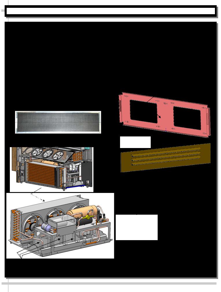
5. Remove Front Panel / Remove Lower Front Grille
Remove by lifting up and off hooks.No screw removal is required.
See illustrations at top-right.
Make certain that magnetic air filter is in place (as shown immediately below and at lower-right).
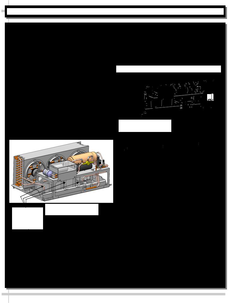
6. Check That No Shifting or Separation of Refrigeration Assembly Parts Has Occurred
To check refrigeration assembly, remove the (3) base rail screws keeping it secure during shipment.
Refrigeration assembly pan rests on plastic glides. |
Remove Front Panel From Case |
Slide refrigeration assembly out from under case, and |
[Shown Rotated in Below Illustration] |
check that no parts have shifted or separated from |
|
|
|
assembly. |
|
Also, confirm that wicking material is securely in place |
|
(held securely in upright prongs) as shown below-left. |
|
View of Magnetic Air Filter at Front
of Case [After Grille Removed] Remove Lower
Front Grille 
Magnetic Air Filter at Front of


 Case [After Grille Removed]
Remove 2 to 3 Base Rail Screws to Allow Refrigeration Package to Slide Out
From Under Case
Wicking Material |
|
|
|
|
Refrigeration Assembly [Shown Rotated] |
|
|
||
|
Lift Off Front Panel and Lower |
|||
To Be in Place |
|
|
||
|
Slid Out From Under Front of Case |
|
Front Grille From Hooks |
|
|
|
|
||
|
|
|
|
|
|
|
|
|
|
7
INSTALLATION, CONT’D.: CASE STARTUP / CONFIRMING EVAPORATOR COIL FAN DISCHARGE
7. Turn On Power To Case
Caution! Before turning on main power switch, confirm that no obstructions to fan blades or other moving parts exist. Lift up deck pans to check for obstructions.
Power cord [located at case rear] should already be plugged into outlet. See INSTALLATION section of this manual.
If there is no power cord, case is to be field-wired at rear. See FIELD ACCESS [CASE REAR] section in this manual for specifics on field wiring.
Access main power switch by removing front grille.
Main power switch is located on main electrical box, below controller. See illustration at top-right.
8. Confirm Evaporator Coil Fan Discharge
When main power switch is turned on, refrigeration assembly will energize (see CASE START-UP & REFRIGERATION ASSEMBLY ACCESS section).
Evaporator coil fans should turn on.
From inside of case, check for discharge air from front baffle (shown below), to confirm that fans are functioning properly.
Caution! Evaporator fans have protective fan guard to prevent injury caused by spinning fan blades. Do not remove fan guard!
Check that cold air is beginning to circulate.
When the case is in a start up mode or has been idle for a long period of time, a 75 minute run time is required to fully achieve set point temperatures.
See below illustration.
Front Baffle 
Deck Pan
Evaporator Fans
[Shown With
Fan Guard
Attached
Main Power
Switch
 On
On
Carel®
Off Temperature
Controller
Note Illustrations shown may not reflect every feature or option
of your particular case.
Case shown with
End Panel Removed
For Illustrative
Purposes Only
8
INSTALLATION, CONT’D.: FRONT PANEL BRACKET REMOVAL & ATTACHMENT TO FRONT PANEL
9. Front Panel Bracket Removal
Assembly Note: Front panel bracket is to be removed and attached to front panel [or wood cladding] as part of setup.
Brackets with holes (for screws) are provided at specific locations to attach front panel (or wood cladding).
Illustration and photo (below) shows various locations of brackets to which attach.
Front panel support bracket is removable WITHOUT screw removal. Simply remove by lifting up and off
hooks. See photo below.
Screws hold lower side brackets in place.
Depending Upon Front Panel (or Wood Cladding)
Design, Lower Side Brackets May Be Unscrewed and Removed (To Attach Front Panel or Wood Cladding Pieces). Both Sides.
See illustrations below.
See cover sheet of manual for sample illustrations of BOTH cladded and un-cladded cases.
See more specific front panel attachment instructions on next page.
View of Front Panel Support
Bracket Attached to Front Panel
Removable Front Panel Support Bracket Shown Being Removed From Case (Wood Cladding To Be Attached to Bracket and Then Replaced).
Note: No screws required for removal! See next page for attachment instructions.
Depending Upon Wood Cladding Design,
These Lower Side Brackets May Be
Unscrewed and Removed (To Attach
Wood Cladding Pieces). Both Sides.
9

INSTALLATION, CONT’D.: FRONT PANEL BRACKET ATTACHMENT TO FRONT PANEL & CASE
10. Front Panel Attachment Instructions, Cont’d
Assembly Note: Case ships without front panel / wood cladding on exterior and is not included with the NSF Certification.
Panel brackets with holes (for screws) are provided to attach wood cladding.
Illustrations show BACK SIDE of front panel being attached to front panel support bracket.
Place screws into the wood cladding at the four
(4) vertical or horizontal obrounds at each of the four (4) corners of front panel support bracket.
Place the newly assembled front panel onto the four (4) retaining hooks.
Top Surface of Front
Ledge (Shown Here)
To Be Flush With
Top of Front Panel
Retaining Hook
(For Front
 Panel). One at
Each End.
Check that the top edge of the front panel wood piece is FLUSH with the top surface of front ledge (as shown in illustration below).
Remove and adjust accordingly.
Important! Front panel must be easily removable from case (by lifting up and off retaining hooks). Easy removal is for access to both refrigeration package and base.
When proper fit is attained, place screws in the eight (8) LOCKING SCREW HOLES (as shown in illustration below).
Top of Front Panel (Here) to Be
Flush With Top Surface of Front
Ledge (See Location Above)
Slot for Front Panel Hook (One at Each End)
Horizontal
Obround
(Typical)
Vertical Obround |
Locking Screw |
(Typical) |
Hole (Typical) |
40. |
|
|
15” |
|
|
↑ UP |
.75” |
Each Side |
|
|
1.68”
Front |
|
Panel |
|
Support |
|
Bracket |
18.63” |
--- Front Panel ( |
|
Back Side) --- |
|
10
SETUP: OPTIONAL NIGHT AIR CURTAIN OPERATING INSTRUCTIONS
1. Night Air Curtain Operating Instructions
1.Use caution when handling Night Air Curtain.
2.Grasp the handle and pull downward to desired location (see illustration below).
3.Magnets will hold Night Air Curtain in place.
4.To return Night Air Curtain to its retracted position, grasp handle, lift up and away from its magnetic attachment and carefully wind Night Air Curtain back into roll.
5.Caution! Do not allow spring-loaded Night Air Curtain to freely snap back into roll. Doing so can eventually destroy Night Air Curtain’s tension and retractability.
6.To entirely detach Night Air Curtain from case, slide Night Air Curtain toward rear of case, freeing it from its ‘keyhole’ slots. Lift upward and away from case.
Note: For cleaning instructions, see CLEANING SCHEDULE - TO BE PERFORMED BY STORE PERSONNEL section in this manual.
Night Air
Curtain Magnet
(One at Each Side
of Night Air Curtain
Handle)
NOTE: MODEL SHOWN MAY NOT EXACTLY REFLECT EVERY FEATURE OR OPTION OF YOUR CASE. HOWEVER, GENERAL NIGHT CURTAIN PLACEMENT AND OPERATION IS THE SAME.
Night Air
 Curtain
|
Night Air Curtain |
|
Attachment Points |
Night Air |
(at Outside of Air |
Deflector) |
|
Curtain Handle |
|
11

|
SETUP, CONTINUED: SEISMIC BRACKET RETROFIT INSTRUCTION SHEET |
|
|
|
|
P/N 20-06349 |
|
|
|
|
|
|
|
|
|
||
|
|
|
|
|||||
|
|
|||||||
|
|
|
|
|
|
|
|
|
|
|
|
|
|
|
|
|
|
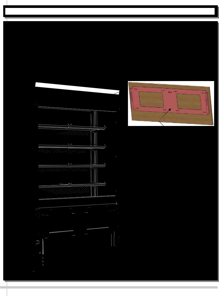
2. Seismic Bracket Retrofit Parts and Instructions
A. Each Kit Consists of the Following:
Two (2) BracketsEight Wood Screws
B. Retrofit Instructions:
Position as shown in illustration below (within 1” of front of end panel).
Use SCC-supplied woodscrews to attach seismic brackets to inside of end panels and into sides of units positioned at left and right of case.
See illustrations below.
12
 Loading...