


READ AND SAVE THESE INSTRUCTIONS
INSTALLATION AND
OPERATING MANUAL PN 54070
FLORAL UPRIGHT “3-D” THREE-SIDED END-CAP UNIT
Model FR96EC 96 1/8”L x 50 3/4”D x 92 1/4”H**
**With 1” End Panels.
**For Self-Contained Unit. Remote Unit height is 85 5/8”.
888 E. Porter Road · Muskegon, MI 49441 Phone: 231.798.8888 Fax: 231.798.4960 www.structuralconcepts.com
I:\Oper Manuals\Allure\FR96EC_54070.pub |
Rev D Date: 7.22.2010 |
|
|

TABLE OF CONTENTS
|
|
OVERVIEW AND WARNINGS …..…………………..…………………..…….………….....….. |
|
3 |
|
|
|
|
|
|
|
||
|
|
FORK LIFT INSTRUCTIONS …………………………………………………………………….. |
|
4 |
|
|
|
|
INSTALLATION INSTRUCTIONS ………………………………………………………….……. |
|
5-7 |
|
|
|
|
START-UP AND OPERATION ……….. …..….…………………...………...…..………………. |
|
8 |
|
|
|
|
THERMOMETER & CPC® CONTROLLER LOCATION ………………………………………. |
|
9 |
|
|
|
|
SHELF ASSEMBLY REMOVAL & CONVERTIBLE SHELVES ……………………………….. |
|
10 |
|
|
|
|
CONVERTIBLE SHELVING INSTALLATION VIEWS …………………………………………. |
|
11 |
|
|
|
|
LIGHT FIXTURE ACCESS AND REMOVAL ……………………………………………………. |
|
12 |
|
|
|
|
HONEYCOMB AIR DIFFUSER LOCATION, REMOVAL AND INSTALLATION …………….. |
|
13 |
|
|
|
|
REFRIGERATION STUB-UP CONNECTIONS …………………………………………………. |
|
14 |
|
|
|
|
DRAIN RESERVOIR, EVAPORATOR PAN, DRAIN HOSE, PUMP LOCATIONS …………. |
|
15 |
|
|
|
|
SERIAL LABEL LOCATION & INFORMATION LISTED / TECH INFO & SERVICE .…..…… |
|
16 |
|
|
|
|
TROUBLESHOOTING ….…………….…………………………………………….….…………. |
|
17 |
|
|
|
|
CPC® ESC3 CONTROLLER OVERVIEW ….………………………………………………….. |
|
18 |
|
|
|
|
CPC® ESC3 CONTROLLER OPERATION …………………………………………………….. |
|
19 |
|
|
|
|
CPC® ESC3 CHANGING SET POINT CHANGING INSTRUCTIONS .…………………….. |
|
20 |
|
|
|
|
CAREL® TEMPERATURE CONTROLLER SPECIFICATIONS ………………………………. |
|
21-23 |
|
|
|
|
CLEANING SCHEDULE..…………………………………………………...………………….…. |
|
24 |
|
|
|
|
TECHNICAL SERVICE CONTACT INFORMATION & WARRANTY INFORMATION ..…..... |
|
25 |
|
|
|
|
|
|
|
|
|
|
|
|
|
|
|
|
2

OVERVIEW AND WARNINGS
OVERVIEW
These cases should be installed and operated according to the following instructions to insure proper performance.
This unit is designed for the display of products in ambient store conditions where temperatures and humidity are maintained at a maximum of 75° F and 55% relative humidity.
WARNING |
WARNING |
Risk of Electric Shock. |
|
ELECTRICAL |
Disconnect Power Before Servicing Unit |
HAZARD |
|
WARNING
ELECTRICAL
HAZARD
WARNING
KEEP HANDS
CLEAR
WARNING
More Than One Source of Electrical Supply.
Disconnect All Sources Before Servicing.
Employed with units that have separate circuits.
WARNING
Hazardous Moving Parts.
Do Not Operate unit with covers removed.
Fan blades may be exposed when deck panel is removed. Disconnect power before removing deck panel.
3

FORK LIFT INSTRUCTIONS
1. Remove From Skid By Placing Fork Lift At Case Rear
Illustration below shows proper location for forks to be placed to remove case from skid.
Forks MUST slide between casters (see illustration below). Be careful to NOT hit casters.
Forks MUST NOT hit P-Trap (see illustration below).
An approximate 31” space is available for forks to go between casters.
Forks MUST be positioned under Rear-Left and Rear-Right U-Channels for proper support.
Placement of forks at any other locations can cause case to be damaged.
Caution! Due to case length, provide support on both case ends to prevent tipping!
Support |
Support |
Case To |
Case To |
Prevent |
Prevent |
Tipping |
Tipping |
Labels: “Use
Fork Lift In
This Area
Only!
31”
|
Rear-Right |
|
Rear-Left |
U-Channel |
|
P-Trap |
||
U-Channel |
4

INSTALLATION INSTRUCTIONS
2. Position and Level Units
After removal from skid, roll case to location desired.
Using 13/16” wrench, adjust feet until they reach the floor.
Adjust each foot (six total on case) until all casters are slightly raised off the floor and case is level and plumb.
Note: For proper case leveling, this procedure may need to be performed several times on each foot.
See illustrations at right.
4. Electrical Connection
Note: Standard single phase connections required, and must be performed by a certified electrician.
Two 220-Volt electrical circuits with leads are provided.
Remove screws from 4X4 box provided for field hook up.
3. Remote Evaporator Connections
A 220-Volt electrical stub up connection is provided on the rear side at either the top or base of case (per customer request).
Refrigeration stub up connections are provided on the rear side at either the top or base of case per customer request.
|
Adjustable |
|
Foot (Six Total |
Caster |
on Case) |
|
5
INSTALLATION INSTRUCTIONS, CONTINUED
5. Electrical Specifications
See Technical Information Sheet
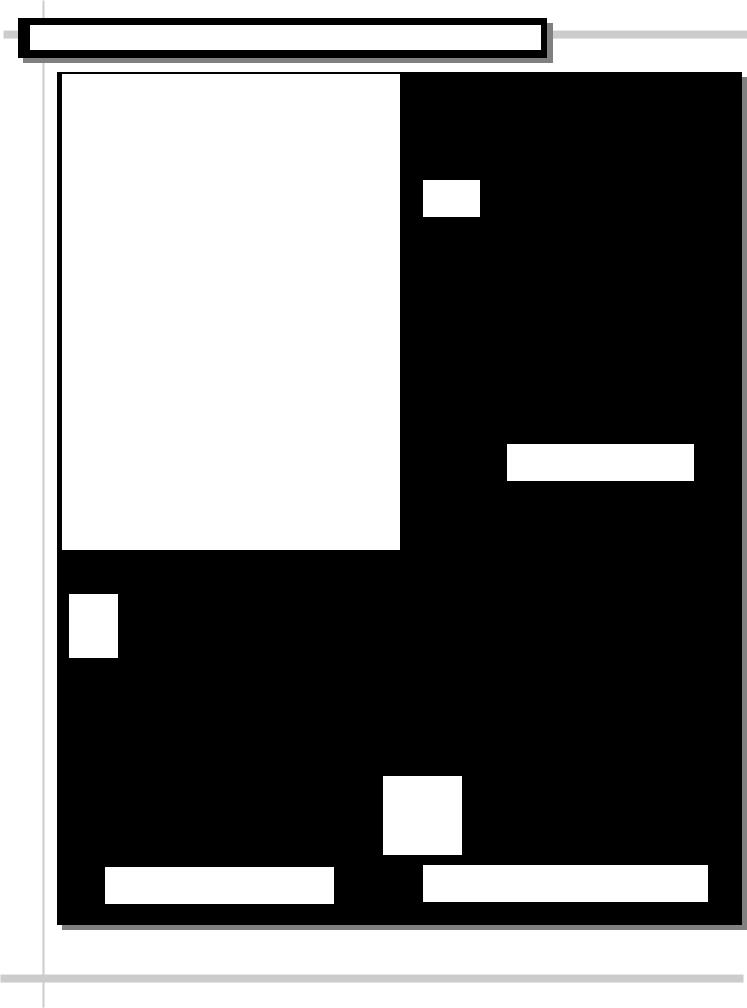
6. Field Wiring Hookup
See Illustration below. Note: Self-Contained Unit shown below.
Whether Remote or Self-Contained unit, Field Wiring Box is in same location.
Field Wiring Box to
Refrigeration Fans, Lights,
Compressor,
Ballasts & CPC® Controller
Field Wiring
Box to
Evaporator
Pan & Pump
Note: CPC® Controller Box shown with cover removed for illustrative purposes only.
6

INSTALLATION INSTRUCTIONS, CONTINUED
7. Skirt Specifics
Skirt is held in place with brackets
Brackets are placed along lower skirt and attaches to top of case.One bracket is to be placed in each of the four (4) corners of skirt.
Whether Remote or Self-Contained, skirt location and positioning is the same.
7
START-UP AND OPERATION
Merchandiser Start-Up
Turn on main power circuit breaker. Coil fans (and in self-contained units, compressor motor) will turn on.
Check to see that coil fans are all functioning
properly. To do so, the following steps must be taken: Square
Buckets
1. Remove the Square Buckets for access to coil fans. See illustration #1.
2. Remove Intake Panels by removing screws (approx. 7 screws per panel). See illustration #2. 3. Access Coil Fans and/or Coil. See illustration
#3.
Check to see if air is discharging properly.
Caution! While fans are rotating, be careful not to put hands or fingers near fan blades. Serious injury can occur.
When main power circuit breaker is turned on, all of the lights should come on at the same time. First time lighting may require short warm up period for bulbs. Slightly dim or a flickering of new bulbs is normal.
Case temperature is set at the factory, as determined by the case size.
Case
Front
Intake
Panel
Right
Side
Intake
Panel
View of Coil
Fans after
removal of
Buckets &
Intake Panel
Illustration #1: View of Case with Square Buckets In Case
Illustration #2: View of Case with Square Buckets removed from Case
Illustration #3: View of Case with Square Buckets and Intake Panel removed from Case
8
 Loading...