


READ AND SAVE THESE INSTRUCTIONS
INSTALLATION &
OPERATING MANUAL PN 5-2434
REFRIGERATED SELF-SERVICE SPECIALTY ISLANDS: ANTIPASTA / OLIVE-CHEESE / SEAFOOD
Model DPI68R.4969
[Front View]
Shown At Left
Model DPI68R.4969
[Rear View]
Shown At Right
Model
DPI716R.4874
Shown At Left
Model
DPI924R.4874A
Shown At Right
Important Note!
Seafood Cases
Require Special
Cleaning Procedures.
Model DPI716R.5602 Shown Above See Cleaning Model DPI924R.5602A Shown Above
Instructions Inside.
888 E. Porter Road · Muskegon, MI 49441 Phone: 231.798.8888 Fax: 231.798.4960 www.structuralconcepts.com
I:\Oper Manuals\CDR\DPI716R-4874_DPI924R-4874A_DPI168R-4969_DPI716R-5602_DPI924R-5602A_5-2434 |
Rev F Date: 5.2.2013 |
|
|

TABLE OF CONTENTS
|
OVERVIEW / NSF® TYPE / COMPLIANCE / WARNINGS / WIRING / GFCI BREAKER USE ….…... |
|
3-4 |
|
|
|
|
|
|
||
|
START-UP: FIELD WIRING WITH ELECTRICAL CORD THRU TOP VS. UNDERSIDE OF CASE ... |
|
5 |
|
|
|
START-UP, CONTINUED: TEMPERATURE SETTINGS ..……………………………………………….. |
|
6 |
|
|
|
DISPENSE-RITE CUP DISPENSER ADJUSTMENT INSTRUCTIONS ………………………………... |
|
7 |
|
|
|
LIGHTING FUNDAMENTALS …………………………………………………………….………………….. |
|
8 |
|
|
|
ADJUSTABLE SHELVING / BRACKETS [MODEL DPI68R.4969 ONLY] ………………………………. |
|
9 |
|
|
|
REFRIGERATION FUNDAMENTALS [MODELS DPI68R.4969 & DPI716R.4874 ONLY] ……………. |
|
10 |
|
|
|
REFRIGERATION FUNDAMENTALS, CONT’D - [MODELS DPI716R.5602 & DPI924R.5602A |
|
|
|
|
|
ONLY] …………………………………………………………………………………………………... |
|
11 |
|
|
|
REFRIGERATION FUNDAMENTALS, CONTINUED …...…………………………………..…………….. |
|
12-15 |
|
|
|
REFRIGERATION FUNDAMENTALS, CONT’D - [MODELS DPI716R.5602 & DPI924R.5602A |
|
|
|
|
|
ONLY] ………………………………………………………………………………………………….. |
|
16 |
|
|
|
HONEYCOMB AIR DIFFUSER PREVENTIVE MAINTENANCE [DPI68R.4969 ONLY] ………………. |
|
17 |
|
|
|
SERIAL LABEL LOCATION & INFORMATION LISTED / TECH INFO & SERVICE……………………. |
|
18 |
|
|
|
CLEANING SCHEDULE - DAILY & WEEKLY ……………………………...……….………….………….. |
|
19 |
|
|
|
CLEANING SCHEDULE - MONTHLY & QUARTERLY ….………………...……….………….………….. |
|
20 |
|
|
|
CARE & CLEANING OF FORMICA® SOLID SURFACING ………………………………………………. |
|
21-22 |
|
|
|
TROUBLESHOOTING ..………………….…………………………………………….….………………….. |
|
23 |
|
|
|
CAREL® TEMPERATURE CONTROLLER INFORMATION ……………...……………………………... |
|
24-26 |
|
|
|
SCC TECHNICAL SERVICE CONTACT INFORMATION & WARRANTY INFORMATION ..…………. |
|
27 |
|
|
|
|
|
|
|
|
|
|
|
|
|
|
2
OVERVIEW / NSF® TYPE / COMPLIANCE / WARNINGS / WIRING / GFCI BREAKER USE - PG 1 of 2
OVERVIEW |
COMPLIANCE |
These Structural Concepts Impulse® self-service cases are designed to merchandise packaged products at a range of temperatures.
The refrigerated 40 °F [4 °C] or less product temperatures.
Cases should be installed and operated according to this operating manual’s instructions to insure proper performance. Improper use will void warranty.
NSF® TYPE
This unit is designed for the display of products in ambient store conditions where temperatures and humidity are maintained within a specific range.
For NSF® Type 1 Conditions (most cases): ambient conditions are to be at 55% maximum humidity and maximum temperatures of 75 °F [24 °C].
See SERIAL LABEL LOCATION & INFORMATION LISTED / TECH INFO & SERVICE section in this manual for sample serial labels).
Performance issues when in violation of applicable NEC, federal, state and local electrical and plumbing codes are not covered by warranty.
See below compliance guideline.
WARNINGS
This page contains important warnings to prevent injury or death.
Please read carefully!
WIRING DIAGRAM INFO / GFCI BREAKER USE RECOMMENDATION / CORD & PLUG MAINTENANCE and HEATED WELL PRECAUTIONS
See next page for WIRING DIAGRAM INFORMATION,
GFCI BREAKER USE RECOMMENDATION, CORD/PLUG MAINTENANCE and HEATED WELL PRECAUTIONS.
COMPLIANCE
WARNING
ELECTRICAL
HAZARD
WARNING
KEEP
HANDS
CLEAR
WARNING
HOT
SURFACE
This equipment MUST be installed in compliance with all applicable NEC, federal, state and local
electrical and plumbing codes.
WARNING
Risk of electric shock. Disconnect power before servicing unit. CAUTION! More than one source of electrical supply is Employed with units that have separate circuits.
Disconnect ALL ELECTRICAL SOURCES before servicing.
WARNING
Hazardous moving parts. If fan blades are exposed, turn off case and allow fan blades to stop before cleaning or servicing.
WARNING
Condenser Pan / Evaporator Tray is Hot!
Disconnect and allow to cool before cleaning or removing from case.
3

OVERVIEW / NSF® TYPE / COMPLIANCE / WARNINGS / WIRING / GFCI BREAKER USE - PG 2 of 2
WIRING DIAGRAM
Each case has its own wiring diagram folded and in its own packet.
Wiring diagram placement may vary; it may be placed near ballast box, field wiring box, raceway cover, or other related location.
POWER CORD AND PLUG MAINTENANCE
Caution! Risk of electric shock.
If cord or plug becomes damaged, replace only with cord and plug of same type.
CAUTION! GFCI BREAKER USE REQUIREMENT
N.E.C. (National Electric Code) or your local code may require GFCI (Ground Fault Circuit Interrupter) protection. In such cases, you MUST use a GFCI breaker in lieu of a GFCI receptacle.
the use of a GFCI breaker is mandatory.
OVERVIEW, NSF TYPE, COMPLIANCE and WARNINGS
See previous page for specifics on OVERVIEW, NSF TYPE, COMPLIANCE and WARNINGS.
CAUTION
WIRING DIAGRAM FORMAT & LOCATION
Each case has its own wiring diagram folded and in its own packet.Wiring diagram placement may vary; it may be placed near ballast box, field wiring box, raceway cover, or other related location.
CAUTION! LAMP REPLACEMENT GUIDELINES
Fluorescent lamps have been treated to resist breakage and must be replaced with similarly treated lamps.
CAUTION! GFCI BREAKER USE REQUIREMENT
If N.E.C. (National Electric Code) or your local code requires GFCI (Ground Fault Circuit Interrupter) protection, you MUST use a GFCI breaker in lieu of a GFCI receptacle.
CAUTION! POWER CORD AND PLUG MAINTENANCE
Risk of electric shock. If cord or plug becomes damaged, replace only with cord and plug of same type.
CAUTION! ADVERSE CONDITIONS / SPACING ISSUES
Performance issues caused by adverse conditions are NOT covered by warranty.
Unit must be kept at least 15-feet from exterior doors, overhead HVAC vents or any air curtain disruption to maintain proper temperatures.
Unit must not be exposed to direct sunlight or any heat source
(ovens, fryers, etc.).
4
START-UP: FIELD WIRING WITH ELECTRICAL CORD THROUGH TOP VS. UNDERSIDE OF CASE
1. Case Start-Up: Field Wiring With Electrical Cord Through Top of Case
When case has cord routed to upper location (through top of case), switch is to be in the “ON / UPPER” position.
Below-left illustration reflects switch position of units wired into ceiling outlet (or hardwired into ceiling junction box).
Switch is shown in the “ON / UPPER” position.
See Field Access Box Location below.
Power Cord / Wiring Route
Through Top of Case 


Field Access
Box 
Switch |
Switch |
|
Design |
||
Design |
||
#2 |
||
#1 |
||
|
2. Case Start-Up: Field Wiring With Electrical Cord Through Underside of Case
When case has cord routed to lower location (through underside of case), switch is to be in the “LOWER / ON” position.
Below-right Illustration reflects switch position of units plugged into floor or wall outlet (or hardwired into junction box).
Switch is shown in the “LOWER / ON” position.
See Field Access Box Location below.
Note:
Illustrations
Shown May Not
Exactly Reflect
Every Feature
or Option of
Your Particular
Case.
Switch |
Switch |
Design |
|
Design |
#2 |
#1 |
|
When case has cord routed to upper location (through top of case), flip switch to “ON / UPPER” position. [Note: Switch Design May Vary]
When case has cord routed to lower location (through underside of case), flip switch to the “LOWER ON” position. [Note: Switch Design May Vary]
5
START-UP, CONTINUED: TEMPERATURE SETTINGS
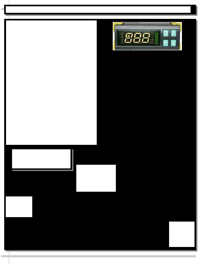
Temperature Settings
This case has been tested to maintain a temperature at or below 4° Celsius / 40° Fahrenheit.
Temperature controller is located next to the main power switch behind the louvered refrigeration package access door. See photo at top right of this sheet.
Open the louvered refrigeration package access door. See illustration at mid-right.
When Main Power Switch is at “ON” position, evaporator coil fans and compressor motor should turn on.
Note: See Previous Page for Main Power
Switch Settings.
Remove several food pans to check that air is circulating through air return column louvers (along inside edge of food bar). See lower-left illustration.
If a temperature setting change is required, refer to the instructions for the Temperature Control Programming operating section of this manual
When the merchandiser is in start-up mode or has been idle for a long period of time, the unit will require a 30 minute time frame to pull-down to proper temperature.
Note:
Illustrations Shown May Not Exactly Reflect Every Feature or Option of Your Particular Case.
Note: Condensate Pans are ONLY on Models DPI716R.4874 and DPI924R.4874A
[Not on Seafood Units With Ice Trays]
Air Return
Column Louvers
(Shown After
Food Pan
Removal)
Refrigeration
Assembly
Removed and
Rotated (For
Illustrative
Purposes)
6

 DISPENSE-RITE CUP DISPENSER ADJUSTMENT INSTRUCTIONS
DISPENSE-RITE® ADJ-1, ADJ-2 & ADJ-3 SERIES
ADJUSTMENT INSTRUCTIONS
FOLLOW THESE INSTRUCTIONS
7
LIGHTING FUNDAMENTALS
1. Standard Fluorescent Style Light Fixtures
When unit is plugged in properly (and main power |
|
Fluorescent |
|
Fluorescent Light |
|||
Light Switch |
|||
switch is turned on), turn on light switch under |
|
||
|
|
||
canopy. See illustration at right. |
|
|
2. Lights Will Turn On
The lights should illuminate immediately. However, first time lighting may require a short warm-up period for the bulbs.
Slightly dim or a flickering of new bulbs is normal.
3. Lamp Removal / Lamp Installation
Removal of lamps:
Grasp lamp firmly and carefully pull downward and out from socket.
See photos at mid-right.
Installation of lamp:
Align pins with slot.
Insert pins into socket and push upward into place.
See photos below.
8

ADJUSTABLE SHELVING / BRACKETS [MODEL DPI68R.4969 ONLY]
Shelf Bracket Adjustment
Brackets are adjustable to allow greater visibility of product.To adjust, lift upward on brackets and rotate front downward.Each notch the bracket is adjusted will change angle by 5°.
See Shelf Bracket Assembly and Shelf Bracket Assembly Side View illustrations below.
|
|
Shelf Bracket |
|
|
Shelf Bracket |
|
|
|
|
|
Assembly |
|
5° Gradient |
|
Assembly |
|
Side View |
|
(To Adjust) |
|
|
|
||
|
|
|
|
|
|
|
|
|
|
Upper & Lower
Shelves and
Adjustable Brackets
9
 Loading...