


|
|
READ AND SAVE THESE INSTRUCTIONS |
|
|||
|
|
|
|
|
|
|
|
|
|
INSTALLATION AND |
|
|
|
|
|
|
|
|
|
|
|
|
|||||
|
PN 54383 |
|||||
|
|
|
OPERATING MANUAL |
|
|
|
|
|
|
|
|
|
|
|
|
|
|
|
|
|
|
|
|
|
|
|
|
34” DEEP COMBINATION CONVERTIBLE SERVICE ABOVE REFRIGERATED SELF-SERVICE CASE
PLEASE NOTE THE FOLLOWING:
1.YOUR SPECIFIC MODEL NUMBER IS ON THE SERIAL LABEL ON CASE REAR (NEAR MAIN POWER SWITCH).
2.SEE “MODELS (AND THEIR RESPECTIVE CASE DIMENSIONS) LISTED IN THIS MANUAL”
SECTION FOR ADDITIONAL INFORMATION REGARDING SPECIFIC CASE DIMENSIONS OF STANDARD MODELS AND CDRs.
3.*[L] DENOTES DIFFERING CASE LENGTHS.
|
|
Note 1: HMBC2 and HMBC3 reflect an |
|
|
|
|
|
|
|
|
|
undivided upper section. |
|
|
|
|
Note 2: HMBC4, HMBC5, HMBC6 reflect a |
|
|
HMBC5 Case Shown Above |
|
divided upper section (as shown above). |
|
|
|
|
|
|
|
|
|
|
|
|
Structural Concepts Corporation · 888 E. Porter Road · Muskegon, MI 49441 Phone: 231.798.8888 Fax: 231.798.4960 · www.structuralconcepts.com
I:\Oper Manuals\Standard\Harmony_Combo_Conv_Svc_Abv_Rfg_Slf-Svc_Oper_Manual_54383.pub |
Rev B Date: 4.11.2011 |
TABLE OF CONTENTS
TABLE OF CONTENTS ……………………………………………………………………………………... |
2 |
MODELS LISTED IN MANUAL / DETERMINING THEIR RESPECTIVE CASE DIMENSIONS…….. |
3 |
OVERVIEW / NSF® TYPE / COMPLIANCE / WARNINGS / PRECAUTIONS …………………...….. |
4-5 |
INSTALLATION: REMOVAL FROM SKID [LEVELERS vs. CASTERS] ...……...…….………………. |
6 |
INSTALLATION: LOWER FRONT GRILLE and LOWER REAR PANEL REMOVAL/REPLACEMENT. |
7 |
INSTALLATION: ELECTRICAL CONNECTIONS ………………………………………………………… |
8 |
INSTALLATION: POSITIONING AND ALIGNING UNITS / GLASS SHELVING ……………………... |
9 |
INSTALLATION: SETUP / POWER CORDS / TEMPERATURE CONTROLLER ……….…………... |
10 |
INSTALLATION, CONTINUED: REMOTE UNIT ELECTRICAL LEADS / REFRIGATION & DRAIN |
|
CONNECTIONS ……………………………………………………………………...…………………….... |
11 |
INSTALLATION: CASTERS / LEVELERS / CURVED GLASS / REAR DOORS ….………………...... |
12 |
INSTALLATION: DISPLAY CASE START-UP, LIGHTS, TEMPERATURE CONTROLLER, SST …. |
13 |
INSTALLATION: FRONT GLASS ALIGNMENT & ADJUSTMENT …………………………………….. |
14 |
BAFFLES: AMBIENT VS. REFRIGERATED CONDITIONS ……………………………………………. |
15 |
OPTIONAL NIGHT AIR CURTAIN INSTALLATION & OPERATING INSTRUCTIONS ……………... |
16 |
SECURITY GRID INSTRUCTIONS (OPTIONAL) ………………………………………………………... 17-18 |
|
DRAIN, HOSE AND BRACKET PLACEMENT ILLUSTRATIONS …………..…………..……….…….. |
19 |
CLEANING SCHEDULE [TO BE PERFORMED BY STORE PERSONNEL] ……....…………...…….. 20-21 |
|
TROUBLESHOOTING [TO BE PERFORMED BY STORE PERSONNEL] ……………………………. |
22 |
MAINTENANCE: LIGHT FIXTURES / REAR SLIDING DOORS [TO BE PERFORMED BY STORE |
|
PERSONNEL]...................................................................................................................................... |
23 |
MAINTENANCE FUNDAMENTALS: BRACKET RETAINERS / SHELVES / DRAIN / TXV VALVE… |
24 |
MAINTENANCE FUNDAMENTALS: REFRIG. PACKAGE., TEMPERATURE CONTROLLER, |
|
CONDENSER PAN ACCESS [TO BE PERFORMED BY TRAINED SERVICE PROVIDERS ONLY] |
25 |
MAINTENANCE FUNDAMENTALS: HONEYCOMB AIR DIFFUSERS / UPPER SECTION AIR |
|
DUCT [SERVICE TO BE PERFORMED BY TRAINED SERVICE PROVIDERS ONLY].…………….. |
26 |
TROUBLESHOOTING [TO BE PERFORMED BY TRAINED SERVICE PROVIDERS ONLY] .……. 27-29 |
|
TROUBLESHOOTING - CONDENSING SYSTEM [TRAINED SERVICE PROVIDERS ONLY] ..….. |
30 |
TROUBLESHOOTING - EVAPORATOR SYSTEM [TRAINED SERVICE PROVIDERS ONLY] …… |
31 |
PREVENTIVE MAINTENANCE [TO BE PERFORMED BY TRAINED SERVICE PROVIDER] …..... 32-33 |
|
SERIAL LABEL INFORMATION & LOCATION ..……………………………………...…....…………..… |
34 |
TEMPERATURE CONTROLLER - CAREL® ...…. ……………………..……..…………………...…….. |
35-37 |
TECHNICAL SERVICE CONTACT INFORMATION & WARRANTY INFORMATION ...……….…..... |
38 |
2
MODELS LISTED IN THIS MANUAL / DETERMINING THEIR RESPECTIVE CASE DIMENSIONS
DETERMINING YOUR MODEL AND ITS CASE DIMENSIONS:
Note 1. Your model number can be found on serial label at rear of case (near main power switch). Note 2. Dimensions of each model can be found at www.structuralconcepts.com. Simply enter the case model number into the Product Number Search box. Click the product specification link for complete dimensions.
Note 3. If your specific model is not found, contact technical service (phone number is listed at Technical Service section in this manual) for dimensions.
Note 4. CDRs (Customer Design Requests) are listed with a 4-digit number. All CDR dimensions are identical to standard model dimensions.
THIS OPERATING MANUAL ENCOMPASSES THE FOLLOWING MODELS (AND THEIR RESPECTIVE CDRs):
Models: HMBC2
HMBC3
HMBC4
HMBC5
HMBC6
3

OVERVIEW / NSF® TYPE / COMPLIANCE / WARNINGS / PRECAUTIONS - PAGE 1 of 2
OVERVIEW
These Structural Concepts Harmony® cases are designed to merchandise packaged products at 41°F [5 °C] or less product temperatures (unless custom cases with wire rack shelving).
Cases should be installed and operated according to this operating manual’s instructions to insure proper performance. Improper use will void warranty.
NSF® TYPE
This unit is designed for the display of products in ambient store conditions where temperatures and humidity are maintained within a specific range.
For NSF® Type 1 Conditions (most cases): ambient conditions are to be at 55% maximum humidity and maximum temperatures of 75 °F [24 °C].
For NSF® Type 2 Conditions: ambient conditions are
to be at 60% maximum humidity and maximum temperatures of 80 °F [27 °C].
If unsure if unit is NSF® Type 1 or 2, see tag next to serial label. See SERIAL LABEL LOCATION &
INFORMATION LISTED / TECH INFO & SERVICE section in this manual for sample serial labels).
COMPLIANCE
Performance issues when in violation of applicable NEC, federal, state and local electrical and plumbing codes are not covered by warranty.
See below compliance guideline.
WARNINGS
Following are important warnings to prevent injury or death.
Please read carefully!
See next page for PRECAUTIONS.
COMPLIANCE
WARNING
ELECTRICAL
HAZARD
WARNING
KEEP
HANDS
CLEAR
WARNING
HOT
SURFACE
This equipment MUST be installed in compliance with all applicable NEC, federal, state and local
electrical and plumbing codes.
WARNING
Risk of electric shock. Disconnect power before servicing unit. CAUTION! More than one source of electrical supply is employed with units that have separate circuits.
Disconnect ALL ELECTRICAL SOURCES before servicing.
WARNING
Hazardous moving parts. Do not operate unit with covers removed. Fan blades may be exposed when deck panel is removed.
Disconnect power before removing deck panel.
WARNING
Condenser Pan is Hot! Disconnect and allow to cool
before cleaning or removing from case.
4
OVERVIEW / NSF® TYPE / COMPLIANCE / WARNINGS / PRECAUTIONS - PAGE 2 of 2
PRECAUTIONS |
|
Please read carefully! |
|||
Following are important precautions to prevent |
|
See previous page for specifics on OVERVIEW, NSF |
|||
damage to unit or merchandise. |
|
TYPE, COMPLIANCE and WARNINGS. |
|||
|
|
|
|
|
|
|
|
|
|
|
|
|
|
|
|
|
|
|
|
|
|
|
|
CAUTION |
CAUTION |
Lamps have been treated to resist breakage |
and must be replaced with similarly treated lamps.
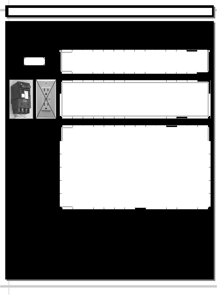
CAUTION
Use the required GFCI (Ground Fault Circuit Interrupter) when electrical code mandates such circuit breaker.
When GFCI is required, DO NOT use standard GFI receptacle.
CAUTION |
CAUTION! ADVERSE CONDITIONS / SPACING ISSUES |
|
Performance issues caused by adverse conditions are NOT covered |
|
by warranty. |
|
End panels must be tightly joined or kept at least 6-inches away |
|
from any structure to prevent condensation. |
|
Unit must be kept at least 15-feet from exterior doors, overhead |
|
HVAC vents or any air curtain disruption to maintain proper |
|
temperatures. |
|
Unit must not be exposed to direct sunlight or any heat source |
|
(ovens, fryers, etc.). |
|
Tile floors, low ceilings or small rooms will increase noise level. |
|
Whisper Cool compressor blanket or remote unit may resolve noise |
|
level issues. |
|
Keep at least 8-inch clearance above unit for air discharge |
|
(self-contained units only). |
5
INSTALLATION: REMOVAL FROM SKID [LEVELERS vs. CASTERS]
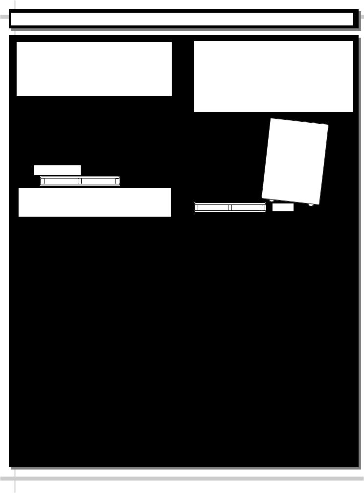
1. Remove Case From Skid (Levelers)
Remove shipping brace that may be securing case to skid.
Support case to prevent tipping.
Caution! Levelers can be damaged if case hits floor with heavy force!
Carefully slide unit to rear of skid and tip backward off skid.
Illustration may not reflect every feature or option of your particular case.
 Slide Skid Out
Case can be repositioned with pallet truck when front lower panel is removed. Blocking may be necessary to obtain adequate height.
2. Remove Case From Skid (Casters)
Remove shipping brackets that may be securing casters to skid
Place ramp up against skid (to allow case to smoothly slide off from skid).
Maintain support of case at all times or center of gravity may cause case to fall.
Unlock Casters. Roll unit to rear of skid.
Roll down ramp and off from skid.
Note: Illustrations |
|
|
shown reflect a |
Support |
|
general outline of |
||
while |
||
sample cases and do |
||
rolling |
||
not reflect features or |
||
case |
||
options of your |
||
down |
||
particular model. |
ramp. |
Ramp |
6

INSTALLATION: LOWER FRONT GRILLE and LOWER REAR PANEL REMOVAL / REPLACEMENT
3. Removing Lower Front Grille
No screw removal is required to remove grille.
Front grille has retainer slots at each end of grille.Case has retainer hooks at each end.
(2) Front Grille
Retainer Slots
(at Each End
of Grille)
(2) Front Grille
Retainer Hooks 
(at Each End of Case)
Simply lift lower front grille up and off retainer hooks (at each end of case).
Replace in same manner.
View below is shown is disassembled for illustrative purposes only.
4. Removing Lower Rear Panel
No screw removal is required to remove panel.
Rear panel has retainer slots at each end of grille.Case has retainer hooks at each end.
Simply lift lower rear panel up and off retainer hooks (at each end of case).
Replace in same manner.
View below is shown is disassembled for illustrative purposes only.
(2) Rear Panel
Retainer Slots
(at Each End
of Rear Panel)
(2) Lower Rear Panel
Retainer Hooks
(at Each End of Case)
7

INSTALLATION, CONTINUED: ELECTRICAL CONNECTIONS
5. Electrical Connections
Ballast Box: Remove 4 screws from the thermostat/ballast cover. Remove screws holding ballast cover to base.
Knockouts are located on side and rear of box for making electrical connections.
Note: Standard 120V or 220V (depending upon case chosen), single phase connections are required for self contained refrigeration units and must be performed by a certified electrician.
View of case with thermostat/ballast cover intact
Thermostat/Ballast Cover
Base
Ballast Cover
Remove two (2) screws at each end of cover to remove thermostat/ballast cover.
Note: Illustrations shown with rear grille removed for illustrative purposes only.
View of case with thermostat/ballast cover removed
Ballasts
Enlarged view of thermostat/ballast area
8
INSTALLATION, CONTINUED: POSITIONING AND ALIGNING UNITS / GLASS SHELVING
6. Position and Aligning Units
Position Units. Align multiple units carefully in areas A & B shown at right.
7. Glass Shelving
Glass shelving will be packed separately.
Caution! Carefully remove from packaging.Grasp firmly and carefully install.
Caution! Check that plastic edging is intact before placing glass shelving onto brackets!
Plastic edging must NOT be removed from glass shelves. Contact Structural Concepts for replacement edging (see TECHNICAL SERVICE CONTACT INFORMATION section).
Check that glass shelving is in proper position before placing product in case.
See illustration below.
A
B
Glass Shelves
(Typical)
9

INSTALLATION, CONTINUED: SETUP / POWER CORDS / TEMPERATURE CONTROLLER
8. Merchandiser Setup: Self Contained Units
Remove lower front grille; see
INSTALLATION: REMOVAL FROM SKID, REMOVING LOWER FRONT GRILLE section in this manual for instructions.
Insure that the Condenser Pan is installed under the PVC condensate drain trap.
Insure that the Condenser Pan is plugged into the receptacle inside base.
Return front grille to case.
See Drain, Hose and Bracket Placement section in Operating Manual for details.
9.a. Self-contained refrigeration with power cord
For your safety, equipment is furnished with a properly grounded cord connector. Do not attempt to defeat the grounded connector.
Plug cord into a certified electrical outlet with ground.
9.b. Self-Contained refrigeration without power cord
Remove the rear lower grille required).
Note: The compressor/condenser assembly can be slid out to facilitate maintenance.
Electrical leads are provided inside the base exiting the ballast box.
Leads are labeled for identification.
9.c. Self-Contained Temperature Controller
See below for location.
See Temperature Controller section for additional information.
PVC Condensate |
Temperature |
|
Drain |
||
Controller |
||
|
Condenser
Pan
Above view shown with rear panel and end panel removed for illustrative purposes only.
10
INSTALLATION, CONTINUED: REMOTE UNIT ELEC. LEADS / REFRIG. & DRAIN CONNECTIONS
10. Merchandiser Setup: Remote Units Remote Refrigeration System
Note: Service to be accomplished by refrigeration / electrical contractor.
10.a. Electrical leads
Remove screws from rear wire-way cover to access electrical leads.
Wiring may run case to case.
Knockout is provided in bottom of wireway for stub-up connection.
Separate leads for lights that are labeled accordingly.
10.b. Refrigerant Connection
Remove the front panel.
Refrigerant stub-up access opening is at the front on the left hand side of the base.
Case
Front
Drain Connection
General Location
Evaporator Stub
Ups Access 
Route refrigerant lines thru access hole.Remove tube caps from stub up
connections
Sweat the high and low pressure connections.
Fill access hole with suitable filler to insure watertight integrity of tub.
10.c. Drain Connection
1” male PVC stub-up connection is under the case on the right hand side.
Remove the front panel.
Remove the rear panel (optional).
Connect tub drain to floor drain. Maintain 1/4” fall per foot to provide proper drainage.
Below illustration may not exactly reflect every feature or option of your case.
Case
Rear
11
INSTALLATION, CONTINUED: CASTERS / LEVELERS / CURVED GLASS / REAR DOORS
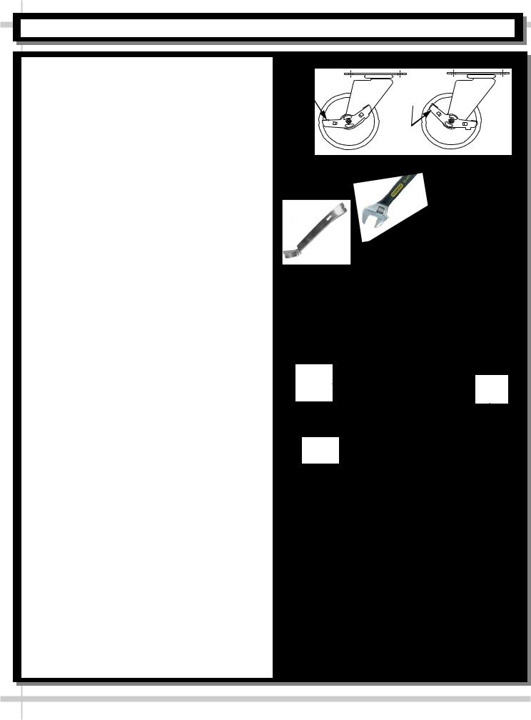
11. Cases With Casters: Lock and Unlock
To lock casters, press down on lever.To unlock casters, pull lever up.
See illustration at right.
12. Cases With Levelers: Adjust Levelers
After case is in position, adjust case so it is level and plumb (see illustration at right).
You may need to remove front and/or rear Toe-Kick to access levelers.
Use adjustable wrench (and possibly a pry bar) to adjust leveler.
Do not use pry bar on toe-kick (it may buckle).Do not use pry bar on end panel (it may chip).Use pry bar ONLY on base frame to avoid
damaging case.
Use a block to reach base frames with pry bar.See illustrations at right.
13. Raising the Curved Glass
To raise the curved glass, grab the lift handle extrusion on the bottom edge of the front curved glass and lift up.
Gas cylinders hold the glass open for hands free access to the interior of the case.
14. Removing the Rear Doors
Move rear doors toward center of the case.
Individually lift each door up toward the top of the case; pivot the bottom of the door out.
15. Electrical Wiring Diagram
Each case has its own wiring diagram folded and in its own packet.
Wiring diagram placement may vary; it may be placed near condenser fan cover, ballast box, raceway cover, or other related location.
16. Ventilation and Clearance
Self-Contained refrigerated cases must maintain airflow clearance of 6” (minimum) to 12” (recommended) at front and rear.
Restriction of air can void warranty.See illustration at right.
|
ed |
d |
k |
e |
|
k |
||
Loc |
|
c |
|
n |
|
|
|
lo |
|
|
U |
Adjustable
Wrench
Pry Bar
Block
Base
Frame
Leveler Toe-Kick 
Front |
|
Curved |
Rear |
Glass |
Doors |
Lift
Handle
 Check air grilles for obstructions.
  Maintain airflow clearance of 6” (min.) to 12” (recommended) at front & rear.
12
 Loading...