


B62

M O B I L E S E R I E S
READ AND SAVE THESE INSTRUCTIONS
INSTALLATION & OPERATING
MANUAL - SCC P/N 54110
Note: See Next
Page For All
Models Covered
By This Manual
Model B42C Model B32
(With Optional Roll-Down Security Cover)
Model B4732
Model B8832 (With Optional
Roll-Down Security Cover)
888 E. Porter Road · Muskegon, MI 49441 Phone: 231.798.8888 Fax: 231.798.4960 www.structuralconcepts.com
I:\Oper Manuals\Oasis\B32_B36_B42_B42C_B47_B59_B62_B71_B82_B88_B92_54110.pub
Model B43C
Rev U Date: 1.8.2014
TABLE OF CONTENTS / MODELS and DIMENSIONS
OVERVIEW / TYPE / COMPLIANCE / WARNINGS / PRECAUTIONS / WIRING / PLUGS …………....
INSTALLATION: CASE REMOVAL / POSITIONING & ALIGNING CASE ………………………………..
INSTALLATION, CONT’D: OPTIONAL SECURITY COVER INSTRUCTIONS …………………………..
FRONT GRILLE ACCESS / CHECK CONDENSER PAN / REFRIGERATION ASS’Y / TURN ON
POWER ……………………………………..………………….…………………………...…………..
CHECK EVAPORATOR COIL FAN DISCHARGE / TXV [THERMOSTATIC EXPANSION VALVE] ..…
HONEYCOMB AIR DIFFUSER ACCESS ……………………………………...…...…………….………….
HONEYCOMB AIR DIFFUSER REMOVAL / INSTALLATION ……………………....…………….…...….
LIGHT FIXTURES [FLUORESCENTS & MINI-LEDs] ...…………………………………………………….
OPTIONAL ROLL-DOWN SECURITY COVER - MODEL B4732 ILLUSTRATED ...…………………….
WALL SPACING / REAR VENTING - MODEL B43C ONLY ……………………………………………….
CONDENSATE PAN ACCESS: STANDARD UNITS ………..………………………………………..….....
CONDENSATE PAN ACCESS: REMOTE UNITS WITH CONDENSATE PANS ONLY ………….........
SELF-CONTAINED HOT GAS LOOP CONDENSATE PACKAGE LAYOUTS …………………………..
LOAD LEVEL GUIDE / TEMPERATURE GUIDE [MODEL B42 SHOWN / APPLICABLE TO ALL
OTHER MODELS IN MANUAL] …..……………………………………………………………… …..
CLEANING SCHEDULE [TO BE PERFORMED BY STORE PERSONNEL] …..……………….………..
PREVENTIVE MAINTENANCE [TO BE PERFORMED BY TRAINED SERVICE PROVIDERS ONLY]
TROUBLESHOOTING [TO BE PERFORMED BY TRAINED SERVICE PROVIDERS ONLY] .…..……
TROUBLESHOOTING [BY TRAINED SERVICE PROVIDERS ONLY] - CONDENSING SYSTEM ......
TROUBLESHOOTING [BY TRAINED SERVICE PROVIDERS ONLY] - EVAPORATOR SYSTEM .….
SERIAL LABEL LOCATION & INFORMATION LISTED / TECH INFO & SERVICE ……….…..…...…..
CAREL® CONTROLLER OPERATING INSTRUCTION …………………………………………..………..
TECHNICAL SERVICE CONTACT INFORMATION & WARRANTY INFORMATION …...………..…….
3-4
5
6
7
8
9
10
11-12
13
14
15
16
17
18
19
20-22
23-25
26
27
28
29-31
32
Models and Dimensions
Model B32: 36”L* x 24”D x 81”H~
Model B3632: 36 5/8”L* x 32”D x 82 1/4”H~
Model B42: 47”L* x 24”D x 81”H~
Model B42C: 45”L* x 31 3/4”D x 81 7/8H~
Model B43C: 39 7/8”L* x 36 3/4D” x 61 1/4”H~
Model B4732: 47 1/2* x 32”D x 82 1/4”H~
*Includes End Panels / ~ With Adjustable Levelers Extended 1 5/8” Below Base Frame
Model B5932: 59 1/2* x 32”D x 82 1/4”H~
Model B62: 68”L* x 24”D x 81”H~
Model B7132: 71 5/8”L* x 32”D x 82 1/4”H~
Model B82: 90”L* x 24”D x 81”H~
Model B8832: 88 1/4”L* x 32”D x 82 1/4”H~
Model B9232: 92 5/8”L* x 32”D x 82 1/4”H~
2

OVERVIEW / TYPE / COMPLIANCE / WARNINGS / PRECAUTIONS / WIRING / PLUGS - PAGE 1 of 2
OVERVIEW
These Structural Concepts merchandisers are
designed to merchandise packaged products at 41 °F
[5 °C] or less product temperatures.
Product must be pre-chilled to 41 °F [5 °C] or less
product temperatures prior to placing in merchandiser.
Cases should be installed and operated according to
this operating manual’s instructions to ensure proper
performance.
Improper use will void warranty.
CASE TYPE
This unit is designed for the display of products in ambient
store conditions where temperatures and humidity are
maintained within a specific range.
For Type 1 Conditions (most cases): ambient
conditions are to be at 55% maximum humidity and
maximum temperatures of 75 °F [24 °C].
For Type 2 Conditions: ambient conditions are to be
at 60% maximum humidity and maximum
temperatures of 80 °F [27 °C].
If unsure if unit is designed for Type 1 or 2, see tag
next to serial label. See SERIAL LABEL LOCATION
& INFORMATION LISTED / TECH INFO & SERVICE
section in this manual for sample serial labels.
COMPLIANCE
Performance issues when in violation of applicable
NEC, federal, state and local electrical and plumbing
codes are not covered by warranty.
See below compliance guideline.
WARNINGS
This sheet contains important warnings to prevent
injury or death.
Please read carefully!
PRECAUTIONS, CORD/PLUG MAINTENANCE &
WIRING DIAGRAM INFORMATION
See next page for PRECAUTIONS, CORD/PLUG
MAINTENANCE and WIRING DIAGRAM information.
WARNING
ELECTRICAL
HAZARD
WARNING
KEEP
HANDS
CLEAR
WARNING
HOT
SURFACE
COMPLIANCE
This equipment MUST be installed in compliance with
all applicable NEC, federal, state and local
electrical and plumbing codes.
WARNING
Risk of electric shock. Disconnect power before servicing unit.
CAUTION! More than one source of electrical supply is
employed with units that have separate circuits.
Disconnect ALL ELECTRICAL SOURCES before servicing.
WARNING
Hazardous moving parts. Do not operate unit with covers removed.
Fan blades may be exposed when deck panel is removed.
Disconnect power before removing deck panel.
WARNING
Condensate Pan is Hot!
Disconnect and allow to cool
before cleaning or removing from case.
3

OVERVIEW / TYPE / COMPLIANCE / WARNINGS / PRECAUTIONS / WIRING / PLUGS - PAGE 2 of 2
PRECAUTIONS
This sheet contains important precautions to prevent
damage to unit or merchandise.
Please read carefully!
See previous page for specifics on OVERVIEW,
TYPE, COMPLIANCE and WARNINGS.
CAUTION! LAMP REPLACEMENT GUIDELINES
LED lamps reflect specific size, shape and overall design.
CAUTION
Any replacements must meet factory specifications.
Fluorescent lamps have been treated to resist breakage and
must be replaced with similarly treated lamps.
CAUTION! GFCI BREAKER USE REQUIREMENT
If N.E.C. (National Electric Code) or your local code
requires GFCI (Ground Fault Circuit Interrupter) protection,
you MUST use a GFCI breaker in lieu of a GFCI receptacle.
CAUTION! POWER CORD AND PLUG MAINTENANCE
Risk of electric shock. If cord or plug becomes damaged,
replace only with cord and plug of same type.
WIRING DIAGRAM
Each case has its own wiring diagram folded and in its
own packet.
Wiring diagram placement may vary; it may be placed
near ballast box, field wiring box, raceway cover, or
other related location.
CAUTION
CAUTION! ADVERSE CONDITIONS / SPACING ISSUES
Performance issues caused by adverse conditions are NOT warranted.
End panels must be tightly joined or kept at least 6-inches away from
any structure to prevent condensation.
Unit must be kept at least 15-feet from exterior doors, overhead HVAC
vents or any air curtain disruption to maintain proper temperatures.
Unit must not be exposed to direct sunlight or any heat source
(ovens, fryers, etc.).
Tile floors, low ceilings or small rooms increase noise level. Whisper
Cool compressor blankets or remote units resolve noise level issues.
CAUTION! CHECK CONDENSATE PAN POSITION & PLUG
Water on flooring can cause extensive damage!
Before powering up unit, check and confirm that:
Condensate pan is DIRECTLY UNDER condensate drain.
Condensate pan plug is securely plugged into receptacle.
Overflow pan has plug connected to its box. Units with
optional Clean Sweep™ MUST HAVE two plugs connected.
4
INSTALLATION: CASE REMOVAL / POSITIONING & ALIGNING CASE
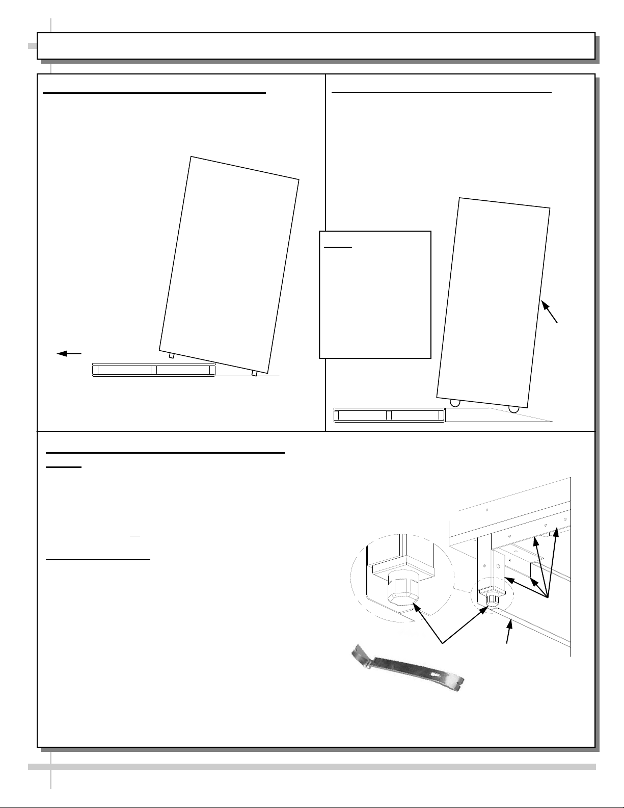
1. Remove Case From Skid (Levelers)
Remove shipping brace that may be securing
case to skid.
Support case to prevent tipping.
Caution! Levelers can be damaged if case hits
floor with heavy force!
Carefully slide unit
to rear of skid and
tip backward off
skid.
Illustration may
not reflect every
feature or option
of your particular
case.
Slide Skid Out
Case can be repositioned with pallet truck when front lower
panel is removed. Blocking may be necessary to obtain
adequate height.
2. Remove Case From Skid (Casters)
Remove shipping brackets that may be securing
casters to skid
Place ramp up against skid (to allow case to
smoothly slide off from skid).
Maintain support of case at all times or center
of gravity may cause case to fall.
Unlock Casters. Roll unit to rear of skid.
Roll down ramp
and off from skid.
Note: Illustrations
shown reflect a
general outline of
sample cases and
do not reflect
features or
options of your
particular model.
Ramp
Support
while
rolling
case
down
ramp.
3. Position & Align Case Alongside Other
Cases
Before adjusting levelers, make certain that the
case is in proper position and, if required, aligned
with adjoining case(s).
This may require the repositioning of the case you
are installing or
4. Adjust Levelers
After case is in proper position, adjust case so it is
level and plumb (see illustration at right).
You may need to remove front and/or rear
Toe-Kick to access levelers.
Use adjustable wrench to adjust leveler.
Depending upon case weight it may be necessary
to use a Pry Bar to accomplish this task.
Do not use Pry Bar on Toe-Kick as it may buckle.
Do not use Pry Bar on End Panel as it may chip.
Use Pry Bar ONLY on Base Frame to avoid
damaging case.
See illustration and photos at right.
the already positioned case(s).
Pry Bar
Adjustable
Wrench
Leveler
Base
Frame
Toe-Kick
5
INSTALLATION, CONT’D: OPTIONAL SECURITY COVER INSTRUCTIONS
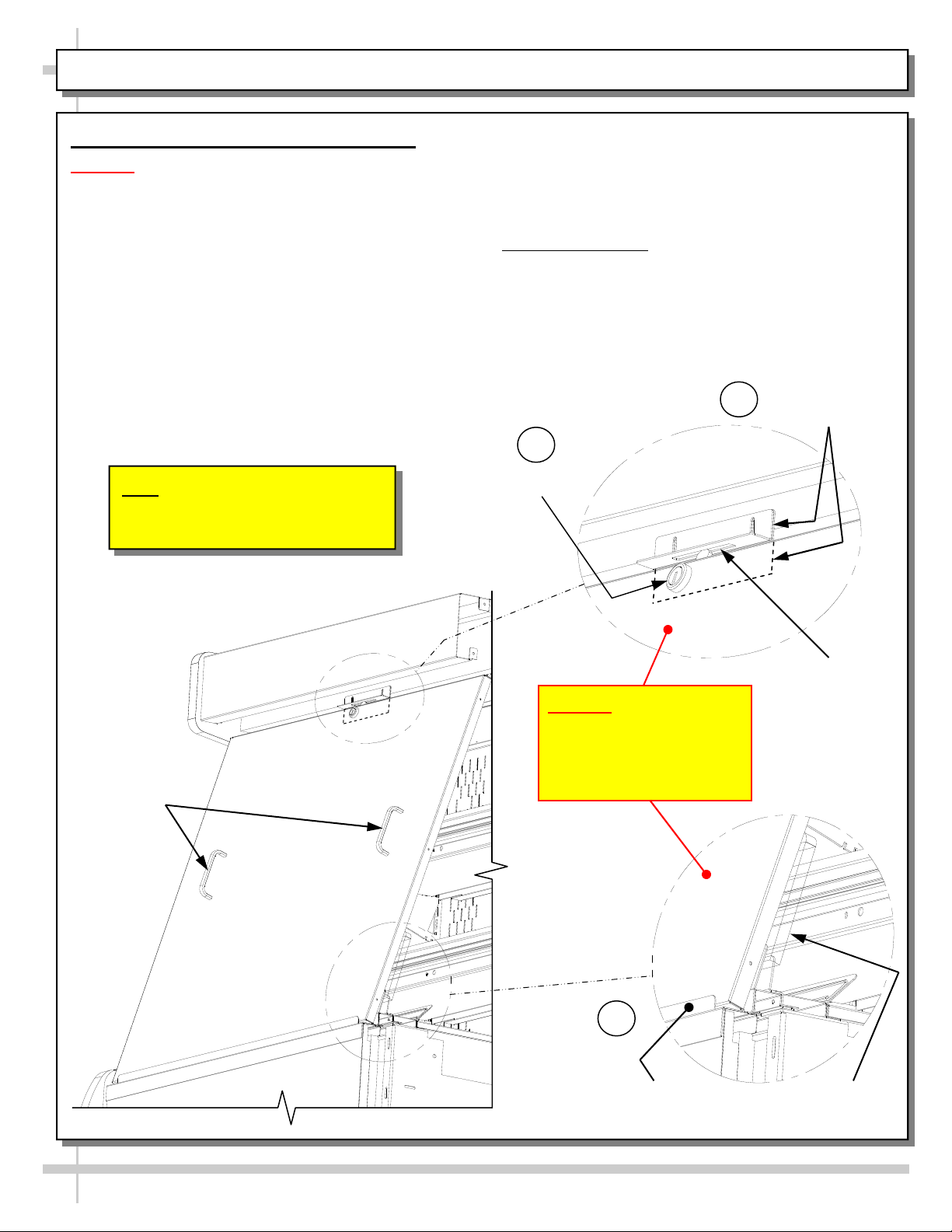
5. Optional Security Cover Instructions
Caution! Security Cover MUST Be Placed On
OUTSIDE of Acrylic Air Deflector and INSIDE
Lower Security Bracket To Fit Properly.
> Steps A, B and C correspond to this sheet’s
illustrations A, B and C. Follow these step-by-step
instructions for proper security cover placement.
A. Firmly hold security cover handles, and place the
bottom of the security cover on the OUTSIDE of
the acrylic air deflector and INSIDE of lower
security bracket.
B. Lean upper edge of security cover against upper
bracket retainer (shown with hidden lines in
illustration ”B” on this sheet).
Note: Illustrations Shown May Not
Exactly Reflect Every Feature or
Option of Your Particular Case.
C. Check that the lock properly rotates its locking
mechanism into support angle slot (at upper
area).
> When removing security cover from case, store in
safe location away from foot traffic.
> Manufacturing note: if your case DOES NOT HAVE
the hardware shown on this sheet for proper
placement of security cover, contact Structural
Concepts Corporation Technical Service. Toll-free
number is listed on the last page of this document.
Upper Bracket
B
Retainer
C
Lock
Security
Cover
Handles
Caution! Security Cover
MUST Be Placed On
OUTSIDE of Acrylic Air
Deflector and INSIDE
Lower Security Bracket
A
Lower Security
Bracket
Support
Angle Slot
Acrylic Air
Deflector
6

FRONT GRILLE ACCESS / CHECK CONDENSER PAN / REFRIGERATION ASS’Y / TURN ON POWER
1. Front Grille
Front grille can be accessed from case by removing two
(2) screws holding grille in place. See illustrations at
top-right.
Remove front grille from front of case.
Front grille may be reattached in same manner.
2. Check That Condensate Pan is Properly
Connected To Outlet
Caution! Condensate pan can come unplugged
from its electrical outlet during shipment!
If case runs without proper connection, water will
overflow condensate pan and drain onto floor causing
damage!
Before turning case on, check that power cord from
condensate pan is properly plugged in.
See TROUBLESHOOTING section in operating manual
for additional information.
One Screw at
Each End
Holds Front
Grille to Case
3. Sliding Refrigeration Assembly Out From
Underside Of Case
At shipment, removal of compressor pan shipment
screws may be necessary to access refrigeration ass’y.
Refrigeration assembly base rests on plastic glides.
Slide refrigeration assembly out from under case.
4. Turning On Power To Case
Plug in power cord.
Main power switch may be turned on by reaching
through front grille; however, removal of front grille will
allow unhindered access.
Main power switch is located on main ballast box,
below controller. See illustration at right.
Controller
Compressor Pan
Shipment Screw
Main Power
Switch
7
View of Condenser Coils After
Removal of Front Grille
View at left is of
Refrigeration Assembly
Slid Out From Under Case

CHECK EVAPORATOR COIL FAN DISCHARGE / TXV [THERMOSTATIC EXPANSION VALVE]
1. Evaporator Coil Fan Discharge
When Main Power Switch is turned on, Refrigeration Assembly will energize (see CASE START-UP &
REFRIGERATION ASSEMBLY ACCESS section).
Evaporator coil fans should turn on. From inside of the case, check for discharge air from front baffle to
confirm that the fans are functioning properly.
When the case is in a start up mode or has been idle for a long period of time, the unit will require 75
minutes of run time to pull-down temperature.
See below illustration.
2. TXV [Thermostatic Expansion Valve]
TXV is under TXV access panel.
Decking must be removed for access.
TXV cover must also be removed for access (remove two thumb screws).
See illustration below.
Note: Standard cases have TXV at customer-left. For cases with EnergyWise, TXV is at customer-right.
Decking
TXV Cover
(shown removed)
Case shown with End Panel, Decking, and TXV Cover removed.
Note
: Illustration above has TXV at customer right. Your case (if standard /
non-EnergyWise refrigeration package) will have TXV accessible at customer-left.
8
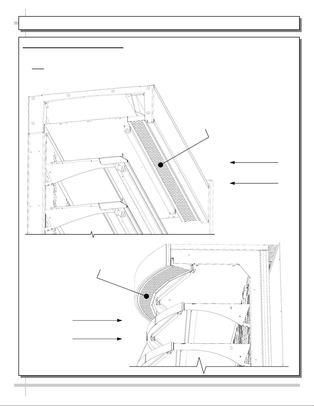
HONEYCOMB AIR DIFFUSER ACCESS
1. Honeycomb Air Diffuser Access
Honeycomb is located in discharge air duct.
See illustration below.
Note: Depending upon model chosen, illustrations shown below may not exactly reflect every design
feature or option as yours.
Honeycomb
Air Diffuser
Majority of Models’
Header Design
Honeycomb
Air Diffuser
Model B43C
Header Design
9
HONEYCOMB AIR DIFFUSER REMOVAL / INSTALLATION
2. Honeycomb Air Diffuser Removal
A. Wedge a non-metallic device of suitable strength
(such as a ballpoint pen) between the honeycomb
and the end panel.
Caution
(that prevents condensation on the lamp assembly).
B. Apply pressure to collapse the honeycomb to
allow it to be pulled out of honeycomb retainer.
C. Carefully pry downward and away from the
honeycomb retainer.
1. Use SCC supplied brush to reach in and, with
outward sweeping motion, pull any crumbs or residue
out of honeycomb area.
2. Clean honeycomb with warm water and soap
solution. Submerse if necessary. Use brush to
dislodge stubborn or sticky residue. Dry by using
vacuum’s blow mode (vs. suction mode).
3. Honeycomb Air Diffuser Installation
D. Squeeze honeycomb to allow it to fit into the
honeycomb retainer.
E. Carefully slide honeycomb into place.
F. Adjust honeycomb so that it fits flat
retainer. It must not be wavy or out of position.
Note: For honeycomb air diffusers in other locations,
these same general instructions apply.
! Use care not to dislodge the heating wire
against
Photos below may not
reflect the exact layout or
design of your particular
honeycomb air diffuser.
A
B
F
D
C
E
10
 Loading...