


READ AND SAVE THESE INSTRUCTIONS

 INSTALLATION &
  OPERATING MANUAL PN 54306
MULTI-PURPOSE SELF-SERVICE REFRIGERATED END CAP MERCHANDISER
Model FSE45R…..……..…37”L* x 52 1/16”D* x 61 9/16”H**
*Includes Bumpers
** With levelers extended 1 5/8” below base frame
888 E. Porter Road · Muskegon, MI 49441 Phone: 231.798.8888 Fax: 231.798.4960 www.structuralconcepts.com
Oper Manuals\Oasis CDR\FSE45R_54306.pub |
|
Rev E Date: 2.06.2012 |
|
|
|

TABLE OF CONTENTS
|
OVERVIEW / NSF® TYPE / COMPLIANCE / WARNINGS / PRECAUTIONS / WIRING ..........……... |
|
3-4 |
|
|
|
|
|
|
||
|
INSTALLATION ……………………………………………...……………………………………..………….. |
|
5 |
|
|
|
START-UP…………………………………………………. …………………………….…………………..... |
|
6 |
|
|
|
MAINTENANCE - FRONT SHELF ASSEMBLY …………………...….……...…………..……………..… |
|
7 |
|
|
|
MAINTENANCE - SIDE SHELF ASSEMBLY / THERMOMETERS ………………....…..…………….… |
|
8 |
|
|
|
MAINTENANCE - LIGHT FIXTURES (LED LIGHT FIXTURES) ….……………….……………………... |
|
9 |
|
|
|
MAINTENANCE FUNDAMENTALS - LED DRIVERS / THERMOSTAT CONTROLLER ….……….…. |
|
10 |
|
|
|
REFRIGERATION FUNDAMENTALS ….………...…………………………..……………….………….... |
|
11 |
|
|
|
SERIAL LABEL LOCATION & INFORMATION LISTED / TECH INFO & SERVICE……………….…... |
|
12 |
|
|
|
GENERAL CLEANING [TO BE PERFORMED BY STORE PERSONNEL] ………………………...….. |
|
13 |
|
|
|
TROUBLESHOOTING [TO BE PERFORMED BY STORE PERSONNEL] ..………………..……….…. |
|
14 |
|
|
|
GENERAL CLEANING [BY TRAINED SERVICE PROVIDERS ONLY] …………….…………………... |
|
15 |
|
|
|
TROUBLESHOOTING [TO BE PERFORMED BY TRAINED SERVICE PROVIDERS ONLY] ………. |
|
16-17 |
|
|
|
TROUBLESHOOTING [BY TRAINED SERVICE PROVIDERS ONLY] - CONDENSING SYSTEM .... |
|
18 |
|
|
|
TROUBLESHOOTING [BY TRAINED SERVICE PROVIDERS ONLY] - EVAPORATOR SYSTEM .... |
|
19 |
|
|
|
PREVENTIVE MAINTENANCE [TO BE PERFORMED BY TRAINED SERVICE PROVIDER] ……... |
|
20 |
|
|
|
MAINTENANCE FUNDAMENTALS - HONEYCOMB AIR DIFFUSERS [TO BE PERFORMED BY |
|
21 |
|
|
|
SERVICE TECHNICIANS ONLY] ………………………………………………………………………….... |
|
|
|
|
|
CAREL® CONTROLLER OPERATING INSTRUCTIONS…………………………….………………..... |
|
22-24 |
|
|
|
TECHNICAL SERVICE CONTACT INFORMATION & WARRANTY INFORMATION …………..….… |
|
25 |
|
|
|
|
|
|
|
|
|
|
|
|
|
|
2
OVERVIEW / NSF® TYPE / COMPLIANCE / WARNINGS / PRECAUTIONS / WIRING - PAGE 1 of 2
OVERVIEW |
COMPLIANCE |
These Structural Concepts merchandisers are designed to merchandise packaged products at 41 °F [5 °C] or less product temperatures.
Cases should be installed and operated according to this operating manual’s instructions to insure proper performance.
Improper use will void warranty.
NSF® TYPE
This unit is designed for the display of products in ambient store conditions where temperatures and humidity are maintained within a specific range.
For NSF® Type 1 Conditions (this case): ambient conditions are to be at 55% maximum humidity and maximum temperatures of 75 °F [24 °C].
Performance issues when in violation of applicable NEC, federal, state and local electrical and plumbing codes are not covered by warranty.
See below compliance guideline.
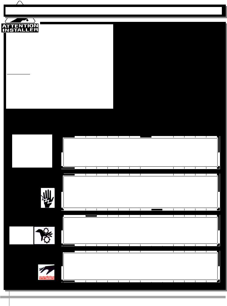
WARNINGS
This page contains important warnings to prevent injury or death.
Please read carefully!
PRECAUTIONS and WIRING DIAGRAMS
See next page for PRECAUTIONS and WIRING DIAGRAM information.
COMPLIANCE
WARNING
ELECTRICAL
HAZARD
WARNING
KEEP
HANDS
CLEAR
WARNING
HOT
SURFACE
This equipment MUST be installed in compliance with all applicable NEC, federal, state and local
electrical and plumbing codes.
WARNING
Risk of electric shock. Disconnect power before servicing unit. CAUTION! More than one source of electrical supply is employed with units that have separate circuits.
Disconnect ALL ELECTRICAL SOURCES before servicing.
WARNING
Hazardous moving parts. Do not operate unit with covers removed. Fan blades may be exposed when deck panel is removed.
Disconnect power before removing deck panel.
WARNING
Condenser Pan is Hot! Disconnect and allow to cool
before cleaning or removing from case.
3
OVERVIEW / NSF® TYPE / COMPLIANCE / WARNINGS / PRECAUTIONS / WIRING - PAGE 2 of 2
PRECAUTIONS |
WIRING DIAGRAM |
|
||
Following are important precautions to prevent |
Each case has its own wiring diagram folded and in |
|
||
damage to unit or merchandise. |
its own packet. |
|
||
Please read carefully! |
Wiring diagram placement may vary; it may be |
|
||
See previous page for specifics on OVERVIEW, NSF |
placed near ballast box, field wiring box, raceway |
|
||
TYPE, COMPLIANCE and WARNINGS. |
cover, or other related location. |
|
||
|
|
|
|
|
|
|
|
|
|
|
|
|
|
|
|
|
|
|
|
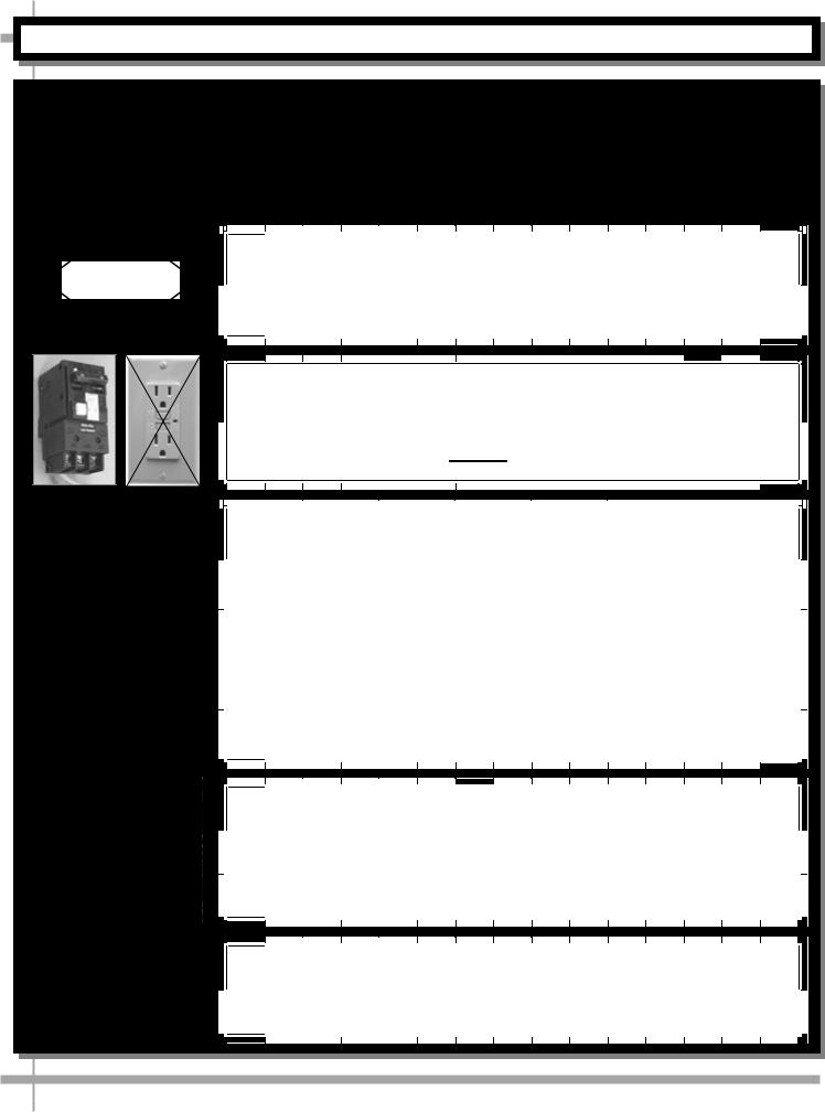
CAUTION
CAUTION! LAMP REPLACEMENT GUIDELINES
Fluorescent lamps have been treated to resist breakage and must be replaced with similarly treated lamps.
CAUTION! GFCI BREAKER USE RECOMMENDATION
If N.E.C. (National Electric Code) or your local code |
requires GFCI (Ground Fault Circuit Interrupter) protection, |
the use of a GFCI breaker is strongly recommended. |
CAUTION |
|
|
|
|
|
|
|
|
|
|
|
|
|
|
|
|
|
CAUTION! ADVERSE CONDITIONS / SPACING ISSUES |
|
|
|||
Performance issues caused by adverse conditions are NOT covered by warranty.
End panels must be tightly joined or kept at least 6-inches away from any structure to prevent condensation.
Unit must be kept at least 15-feet from exterior doors, overhead HVAC vents or any air curtain disruption to maintain proper temperatures.
Unit must not be exposed to direct sunlight or any heat source (ovens, fryers, etc.).
Tile floors, low ceilings or small rooms will increase noise level.
Whisper Cool compressor blanket or remote unit may resolve noise level issues.
CAUTION! CHECK EVAPORATOR PAN POSITION AND PLUG Water on flooring can cause extensive damage!
Before powering up unit, check the following:
Evaporator pan MUST BE positioned directly under condensate drain.Evaporator pan plug MUST BE securely plugged into receptacle.
WIRING DIAGRAM FORMAT & LOCATION
Each case has its own wiring diagram folded and in its own packet.Wiring diagram placement may vary; it may be placed near ballast box, field wiring box, raceway cover, or other related location.
4

INSTALLATION
1. Remove Unit From Skid
For your safety, the equipment is furnished with a properly grounded cord connector. Do not attempt to defeat the grounded connector.
Remove case from skid and place in proper location.
Plug cord into certified electrical outlet with a ground.
2. Position and Level Unit
Position Unit. Level unit by either hand-cranking or using adjustable wrench. (See below right)
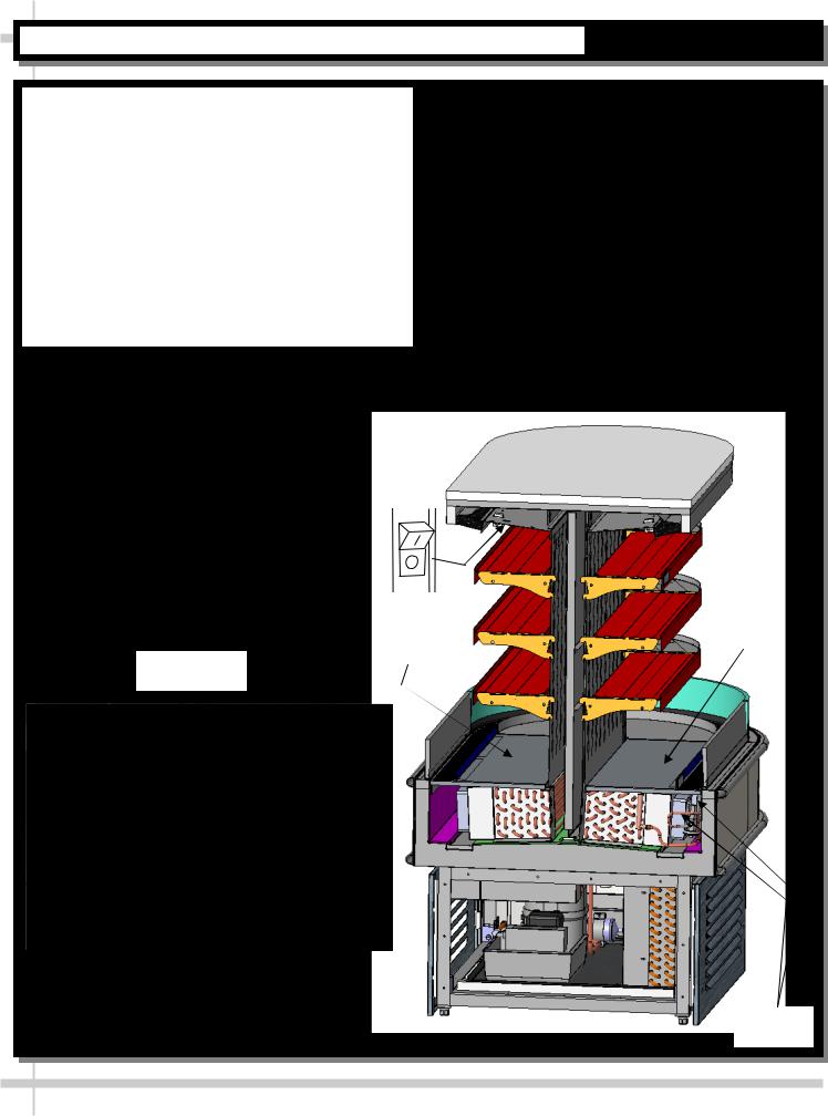
3. Merchandiser Start-Up
Lift off exhaust grill on customer right side of unit. No screw removal required. Simply lift up and off.
Turn on Main Power Switch at right rear side of case.
Main Power Switch will start evaporator coil fans, and the compressor motor.
See illustration below.
Provide support while removing from skid
 Carefully slide skid out from under unit
Leveler
|
|
|
|
|
|
|
|
|
|
|
|
|
|
|
|
|
|
|
|
|
|
|
|
|
|
|
|
|
|
|
|
|
|
|
|
|
|
|
|
|
|
|
|
|
|
|
|
|
|
|
|
|
|
|
|
|
|
|
|
|
|
|
|
|
|
|
|
|
|
|
|
|
|
|
|
|
|
|
|
|
|
|
|
Pry |
Bar |
|
Block |
|
|||||||
|
|
|
|
|
|
|
|
|
|
|
|
|
|
|
|
|
|
|
|
|
|
|
|
Thermostat |
|
Main Power |
Controller |
Ballasts |
Switch |
|
|
Side Panel |
|
|
Slots |
|
5 |
|
START-UP
Merchandiser Start-Up
Evaporator Coil Fans
After power has been supplied, evaporator coil fans and compressor motor will be operational.
To verify fans are operational, lift up deck pans; check to see that the coil fans are all functioning properly.
See illustration at top-right.
Light Switch Location
Light switch is located inside on the plenum top toward back of the unit.
See illustration below.
Note: Light Switch is located inside on plenum top customer right side.
Note: All lights should come on at the same time.
First time lighting may require a short warm up period for the bulbs. Slightly dim or a flickering of new bulbs is normal. If lights do not turn on, check all of the plug connections.
Note: Illustrations shown may not exactly reflect every feature or option of your particular case.
Deck
Pan
Deck Pan Intact
Intact
Deck Pan Being
Raised
View of deck pan being lifted and coil fans being checked.
Evaporator
Fans
6

MAINTENANCE - FRONT SHELF ASSEMBLY
Front Shelf Assembly Removal
Shelving is removable as well as vertically adjustable on 1” centers.
Shelves may be lifted up & out.
Illustrations show shelf assembly hooks and their accompanying slots.
7

MAINTENANCE - SIDE SHELF ASSEMBLY / THERMOMETERS
1. Side Shelf Assembly Removal (Typical on |
2. Thermometer |
Both Sides of Case) |
Thermometers are located in the refrigerated |
Shelves may be lifted up & out. |
compartment are for monitoring warmest air |
Shelving is also vertically adjustable on 1” centers. |
temperature. |
There are bulbs on all side shelves AND at top of |
Thermometers are located on BOTH refrigerated |
case. |
sides of case. |
See illustrations below. |
|
|
|
Bracket Hooks for
Shelf Adjustment 
Thermometer (One at Each
Refrigerated Side of Case)
8
 Loading...