


READ AND SAVE THESE INSTRUCTIONS
INSTALLATION &
OPERATING MANUAL
SELF-SERVICE REFRIGERATED DISPLAY CASE (SELF-CONTAINED & REMOTE)
PLEASE NOTE THE FOLLOWING:
PN 54382
1.YOUR SPECIFIC MODEL NUMBER IS ON THE SERIAL LABEL ON CASE REAR (NEAR MAIN POWER SWITCH).
2.ILLUSTRATIONS SHOWN BELOW LIST “[L]” TO REFLECT VARYING CASE LENGTH DIMENSIONS.
3.CASES SHOWN REFLECT FULL & OPEN END PANELS / STRAIGHT OR ANGLED BASES. YOURS MAY DIFFER.
4.SEE “MODELS (AND THEIR RESPECTIVE CASE DIMENSIONS) LISTED IN THIS MANUAL” SECTION FOR ADDITIONAL INFORMATION REGARDING SPECIFIC CASE DIMENSIONS OF STANDARD MODELS AND CDRs.
HV[L]56RSS |
HV[L]RSS |
|
|
|
Angled Base - Full Ends |
HV48RSS.3635A |
|
|
|
Straight Base |
HV[L]48RSS |
HV28RSS.3635B |
||
|
Cutaway Ends |
Modified Base |
||
|
Straight Base - Full Ends |
Modified Base |
||
|
|
Cutaway Ends |
||
|
|
|
Cutaway Ends |
|
|
|
|
|
HV[L]39RSS (including Q3713) |
HV42[L]RSS |
HV[L]56RSS |
|
|
Straight Base - Full Ends |
HV36112RSS.4863A |
|||
Angled Base - Full Ends |
Straight Base |
|||
HV7439RSS.3713A |
|
Full Ends |
Metal End Panel With Sink |
|
Angled Base - Full Ends |
|
|
|
HV[L]RSSRD |
HVK[L]RSS |
RG2Z5080 |
HV36112RSS.4922B |
Straight Base - Full Ends |
“K” Series |
|
With Patisserie in Top Section |
Rear Sliding Doors - Plexi Plenum |
Straight Base - Full Ends |
|
[See Patisserie Section in Manual] |
Structural Concepts Corporation · 888 E. Porter Road · Muskegon, MI 49441 |
Phone: 231.798.8888 |
Fax: 231.798.4960 www.structuralconcepts.com |
|
|
|
|
|
|
|
|
|
Oper Manuals\Standard\Self_Service_Refrig_Oper_Manual_54382.pub |
|
Rev J Date: 8.25.2011 |
|

TABLE OF CONTENTS
|
|
TABLE OF CONTENTS ……………………………………………………………………………………... |
|
2 |
|
|
|
|
|
|
|
||
|
|
MODELS LISTED IN MANUAL (AND DETERMINING THEIR RESPECTIVE CASE DIMENSIONS) |
|
3 |
|
|
|
|
OVERVIEW / NSF® TYPE / COMPLIANCE / WARNINGS / PRECAUTIONS / WIRING ...……...….. |
|
4-5 |
|
|
|
|
INSTALLATION: REMOVAL FROM SKID, REMOVING LOWER FRONT PANELS ..……...…….….. |
|
6 |
|
|
|
|
INSTALLATION: ADJUSTING FRONT PANELS / ADJOINING UNITS / GLASS SHELVING ………. |
|
7 |
|
|
|
|
INSTALLATION: ELEC. CONNECTIONS / LOCKING CASTERS / ADJUSTING LEVELERS ……… |
|
8 |
|
|
|
|
INSTALLATION: REFRIG. LINES / STUB-UPS / DRAINS / WIRING DIAGRAMS / VENTILATION .. |
|
9 |
|
|
|
|
INSTALLATION: DISPLAY CASE START-UP ……………………………………………………………. |
|
10 |
|
|
|
|
DRAIN, HOSE AND BRACKET PLACEMENT ………………………………..…………..……….…….. |
|
11 |
|
|
|
|
NIGHT AIR CURTAIN OPERATING INSTRUCTIONS (OPTIONAL) …………..…………...…………. |
|
12-13 |
|
|
|
|
SECURITY GRID INFORMATION ……………………………………………………..……..….………... |
|
14-15 |
|
|
|
|
MAINTENANCE FUNDAMENTALS - STANDARD LIGHT FIXTURES ...…………..……..…….……... |
|
16 |
|
|
|
|
MAINTENANCE FUNDAMENTALS - LED LIGHTS/BRACKETS/SHELVES/DRAIN/TXV VALVE …. |
|
17 |
|
|
|
|
MAINTENANCE FUNDAMENTALS - REFRIG. PKG., TEMP. CONTROLLER, EVAP. PAN ……….. |
|
18 |
|
|
|
|
MAINTENANCE FUNDAMENTALS - REAR DOORS / REAR PLENUM / MAGNETIC AIR FILTER . |
|
19 |
|
|
|
|
MAINTENANCE OF PATISSERIE AREA (MODEL HV36112RSS.4922B ONLY) …………………... |
|
20-21 |
|
|
|
|
GENERAL CLEANING [TO BE PERFORMED BY STORE PERSONNEL] ………………..……...….. |
|
22 |
|
|
|
|
TROUBLESHOOTING [TO BE PERFORMED BY STORE PERSONNEL] ..………..…….……….…. |
|
23 |
|
|
|
|
GENERAL CLEANING [BY TRAINED SERVICE PROVIDERS ONLY] ……………………...………... |
|
24 |
|
|
|
|
TROUBLESHOOTING [TO BE PERFORMED BY TRAINED SERVICE PROVIDERS ONLY] ……... |
|
25-27 |
|
|
|
|
TROUBLESHOOTING [BY TRAINED SERVICE PROVIDERS ONLY] - CONDENSING SYSTEM.... |
|
28 |
|
|
|
|
TROUBLESHOOTING [BY TRAINED SERVICE PROVIDERS ONLY] - EVAPORATOR SYSTEM... |
|
29 |
|
|
|
|
PREVENTIVE MAINTENANCE [TO BE PERFORMED BY TRAINED SERVICE PROVIDER]……... |
|
30 |
|
|
|
|
MAINTENANCE FUNDAMENTALS - HONEYCOMB AIR DIFFUSERS [TO BE PERFORMED BY |
|
|
|
|
|
|
SERVICE TECHNICIANS ONLY] ………………………………………………………………………….. |
|
31 |
|
|
|
|
SERIAL LABEL INFORMATION & LOCATION ..……………………………………...…....…………..… |
|
32 |
|
|
|
|
TEMPERATURE CONTROLLER - CAREL® ...…. ……………………..……..…………………...…….. |
|
33-35 |
|
|
|
|
TECHNICAL SERVICE CONTACT INFORMATION & WARRANTY INFORMATION ...……….…..... |
|
36 |
|
|
|
|
|
|
|
|
|
|
|
|
|
|
|
|
2

MODELS LISTED IN THIS MANUAL (AND DETERMINING THEIR RESPECTIVE CASE DIMENSIONS)
DETERMINING YOUR MODEL AND ITS CASE DIMENSIONS:
Note 1. Your model number can be found on serial label at rear of case (near main power switch).
Note 2. Dimensions of most models can be found at www.structuralconcepts.com. Simply enter the case model number into the Product Number Search box. Click the product specification link for complete dimensions.
Note 3. If your specific model is not found, contact technical service (phone number is listed at Technical Service section in this manual) for dimensions.
Note 4. CDRs (Customer Design Requests) are listed with a 4-digit number. All CDR dimensions are identical to standard model dimensions.
THIS OPERATING MANUAL ENCOMPASSES THE FOLLOWING MODELS (AND/OR THEIR RESPECTIVE CDRs):
Standard 2287 2595 2613 2613A 2613B 2852C 3153 3916 HVK3696RSS.5159A HVK36144RSS.5159B HVK48RSS HVK56RSS HVK74RSS HVK74RSS.5142A HVK96RSS HVK96RSS.5142 HVK4296RSS HV28RSS HV28RSS.3635B HV38RSS HV38RSSRD HV48RSS HV48RSS.2917 HV48RSS.3620 HV48RSS.3635A HV48RSS.3735A HV56RSS HV56RSS.3935A HV56RSS.4203 HV74RSS HV74RSS.2846B HV74RSS.2852 HV74RSS.3905B HV96RSS HV96RSS.3905 HV96RSS.4105 HV96RSS.5161 HV112RSS HV112RSS.2852D HV114RSS HV144RSS HV34144RSS HV34144RSS.4993 HV34144RSS.4993A HV3638RSS HV3648RSS HV3656RSS HV3674RSS HV3696RSS HV36112RSS HV36112RSS.4992B HV36112RSS.4863A HV4256RSS HV4274RSS HV4296RSS HV5656RSS HV7439RSS HV38RSSRD HV48RSSRD HV56RSSRD HV74RSSRD HV96RSSRD HV112RSSRD HV74RSS.4104 HVLD48RSS.4125 RG2Z5080 SB4566R
OVERVIEW / NSF® TYPE / COMPLIANCE / WARNINGS / PRECAUTIONS / WIRING - PAGE 1 of 2
OVERVIEW |
to be at 60% maximum humidity and maximum |
|
These Structural Concepts Encore® self-service |
temperatures of 80 °F [27 °C]. |
|
If unsure if unit is NSF® Type 1 or 2, see tag next to |
||
cases are designed to merchandise packaged |
||
serial label. See SERIAL LABEL LOCATION & |
||
products at 41 °F [5 °C] or less product temperatures |
||
INFORMATION LISTED / TECH INFO & SERVICE |
||
(unless custom cases with wire rack shelving). |
||
section in this manual for sample serial labels). |
||
Cases should be installed and operated according to |
||
|
||
this operating manual’s instructions to insure proper |
COMPLIANCE |
|
performance. Improper use will void warranty. |
||
Performance issues when in violation of applicable |
||
|
||
NSF® TYPE |
NEC, federal, state and local electrical and plumbing |
|
This unit is designed for the display of products in |
codes are not covered by warranty. |
|
See below compliance guideline. |
||
ambient store conditions where temperatures and |
||
|
||
humidity are maintained within a specific range. |
WARNINGS |
|
For NSF® Type 1 Conditions (most cases): ambient |
||
Following are important warnings to prevent injury or |
||
conditions are to be at 55% maximum humidity and |
||
maximum temperatures of 75 °F [24 °C]. |
death. |
|
Please read carefully! |
||
For NSF® Type 2 Conditions: ambient conditions are |
||
|
See next page for PRECAUTIONS. |
|
|
|
|
|
|
|
|
|
|
|
|
|
|
|
|
|
|
|
|
|
|
|
|
|
|
|
|
|
|
|
|
|
|
|
|
COMPLIANCE |
|
||||||||
|
|
|
|
|
|
|
|
This equipment MUST be installed in compliance with |
|
||||||||||||
|
|
|
|
|
|
|
|
|
all applicable NEC, federal, state and local |
|
|||||||||||
|
|
|
|
|
|
|
|
|
|
|
electrical and plumbing codes. |
|
|||||||||
|
|
|
|
|
|
|
|
|
|
|
|
|
|
||||||||
|
|
|
|
|
|
|
|
|
|
|
|
|
|
|
|
|
|
|
|
|
|
|
|
WARNING |
|
|
|
|
|
|
|
WARNING |
|
||||||||||
|
|
|
|
|
|
|
Risk of electric shock. Disconnect power before servicing unit. |
|
|||||||||||||
|
|
|
|
|
|
|
|
||||||||||||||
|
ELECTRICAL |
|
|
|
CAUTION! More than one source of electrical supply is |
|
|||||||||||||||
|
|
|
|
|
|||||||||||||||||
|
|
|
|
employed with units that have separate circuits. |
|
||||||||||||||||
|
|
HAZARD |
|
|
|
|
|
||||||||||||||
|
|
|
|
Disconnect ALL ELECTRICAL SOURCES before servicing. |
|
||||||||||||||||
|
|
|
|
|
|
|
|
|
|||||||||||||
|
|
|
|
|
|
|
|
|
|
|
|
|
|
|
|
|
|
|
|
|
|
|
|
|
|
|
|
|
|
|
|
|
|
|
|
|
|
|
|
|
|
|
|
|
|
|
|
|
|
|
|
|
|
|
|
|
|
|
|
|
|
|
|
|
|
|
|
WARNING |
|
|
|
|
|
|
|
|
|
|
|
|
|
|
|
|
|||
|
|
|
|
|
|
WARNING |
|
||||||||||||||
|
|
|
|
|
|
|
|||||||||||||||
|
|
KEEP |
|
|
|
|
Hazardous moving parts. Do not operate unit with covers removed. |
|
|||||||||||||
|
|
|
|
|
|
|
Fan blades may be exposed when deck panel is removed. |
|
|||||||||||||
|
|
HANDS |
|
|
|
|
|
|
|||||||||||||
|
|
|
|
|
|
|
Disconnect power before removing deck panel. |
|
|||||||||||||
|
|
CLEAR |
|
|
|
|
|
|
|
||||||||||||
|
|
|
|
|
|
|
|
|
|
|
|
|
|
|
|
|
|
|
|
||
|
|
|
|
|
|
|
|
|
|
|
|
|
|
|
|
|
|
|
|
|
|
|
|
|
|
|
|
|
|
|
|
|
|
|
|
||||||||
|
|
WARNING |
|
|
|
|
|
|
|
|
|
|
|
|
|
|
|
|
|
||
|
|
|
|
|
|
|
|
|
WARNING |
|
|||||||||||
|
|
|
|
|
|
|
|||||||||||||||
|
|
|
|
|
|
|
|
|
|
|
Condenser Pan is Hot! |
|
|||||||||
|
|
|
|
|
|
|
|
|
|
|
|
||||||||||
|
|
HOT |
|
|
|
|
|
Disconnect and allow to cool |
|
||||||||||||
|
SURFACE |
|
|
|
|
before cleaning or removing from case. |
|
||||||||||||||
4

OVERVIEW / NSF® TYPE / COMPLIANCE / WARNINGS / PRECAUTIONS / WIRING - PAGE 2 of 2
PRECAUTIONS
Following are important precautions to prevent damage to unit or merchandise.
Please read carefully!
See previous page for specifics on OVERVIEW, NSF TYPE, COMPLIANCE and WARNINGS.
WIRING DIAGRAM
Each case has its own wiring diagram folded and in its own packet.
Wiring diagram placement may vary; it may be placed near ballast box, field wiring box, raceway cover, or other related location.
CAUTION
CAUTION
CAUTION
CAUTION
LED lamps reflect specific size, shape and overall design. Any replacements must meet factory specifications.
CAUTION
Fluorescent lamps have been treated to resist breakage and must be replaced with similarly treated lamps.
CAUTION |
If N.E.C. (National Electric Code) or your local code |
requires GFCI (Ground Fault Circuit Interrupter) protection, |
the use of a GFCI breaker is strongly recommended. |
CAUTION! ADVERSE CONDITIONS / SPACING ISSUES
Performance issues caused by adverse conditions are NOT covered by warranty.
End panels must be tightly joined or kept at least 6-inches away from any structure to prevent condensation.
Unit must be kept at least 15-feet from exterior doors, overhead
HVAC vents or any air curtain disruption to maintain proper temperatures.
Unit must not be exposed to direct sunlight or any heat source
(ovens, fryers, etc.).
Tile floors, low ceilings or small rooms will increase noise level.
Whisper Cool compressor blanket or remote unit may resolve noise level issues.
Keep at least 8-inch clearance above unit for air discharge
(self-contained units only).
CAUTION! CHECK EVAPORATOR PAN POSITION AND PLUG Water on flooring can cause extensive damage!
Before powering up unit, check the following:
Evaporator pan MUST BE positioned directly under condensate drain.Evaporator pan plug MUST BE securely plugged into receptacle.
5

INSTALLATION: REMOVAL FROM SKID, REMOVING LOWER FRONT PANELS
1. Remove Case From Skid (Levelers)
Remove shipping brace that may be securing case to skid.
Support case to prevent tipping.
Caution! Levelers can be damaged if case hits floor with heavy force!
Carefully slide unit to rear of skid and tip backward off skid.
Illustration may not reflect every feature or option of your particular case.
Slide Skid Out
Case can be repositioned with pallet truck when front lower panel is removed. Blocking may be necessary to obtain adequate height.
2. Remove Case From Skid (Casters)
Remove shipping brackets that may be securing casters to skid
Place ramp up against skid (to allow case to smoothly slide off from skid).
Maintain support of case at all times or center of gravity may cause case to fall.
Unlock Casters. Roll unit to rear of skid.
Roll down ramp and off from skid.
Note: Illustrations |
|
|
shown reflect a |
Support |
|
general outline of |
||
while |
||
sample cases and do |
||
rolling |
||
not reflect features or |
||
case |
||
options of your |
||
down |
||
particular model. |
ramp. |
Ramp |
3A. Removing Angled Lower Front Panels
Upper panel support.
Remove screws located behind upper front panel.
Lower panel support.
Most applications, screws secure the lower panel support (located below front panel) to the unit.
See illustration at right.
3B. Removing Vertical Lower Front Panels
Front Panel Upper Support
Remove the caps and screws holding Deck Support in place.
Upper
Panel 
Support
Angled
Lower
Front 
Panel
Remove screws. Lift out.
Lower Panel Support
*Apply Upward Pressure
Front Panel Lower Support
For most display cases, screws secure Front Panel Lower Support to Base.
Remove screws holding Front Panel Lower Support to Display Case Base.
Vertical Lower Front Panel can now be removed (see illustration at lower right).
*Alternate applications (for cases without lower panel screws): Apply upward pressure to lower panel support to disengage lower support panel tabs from slots located in base at both ends of unit.
|
Deck |
|
Support |
Front Panel |
|
Upper Support |
Typical |
|
Side |
Vertical Lower |
Panel |
|
|
Front Panel |
|
|
Display |
Front Panel |
Case |
Base |
|
Lower Support |
|
6

INSTALLATION: ADJUSTING FRONT PANELS / ADJOINING UNITS / GLASS SHELVING
4. Adjusting Upper Front Panels
Remove screw cover and loosen adjustment screws.
Adjust alignment and tighten screws.See illustration at mid-right.
5. Bolting and Caulking Units Together
Follow these steps to assure a secure, level lineup.
Remove Screw |
IN / OUT |
Cover Cap |
|
|
UP |
Loosen |
or |
Adjustment |
DOWN |
Screws |
|
A.Begin lineup leveling from highest point of floor.
B.After the ’first’ case is level, apply industrial grade
|
butyl caulk on non-visible areas (at case end). |
|
|
|
|
|
|
|
Use industrial grade silicone sealant on visible |
|
Upper |
|
|
|
|
|
areas (at case end). |
|
Front |
|
|
|
|
C. Form Two (2) Caulk/Sealant Lines: (Sanitation |
|
Panel |
|
|
|
||
|
and Refrigeration). See illustration at mid-right for |
|
|
|
|
IN / OUT |
|
|
outline of caulk/sealant lines. |
|
|
|
|
|
|
D. Line up ‘second’ case bolt-hole to bolt-hole to |
|
|
|
|
|
||
|
‘first’ case. |
Approximate hole |
Sanitation Bead |
Refrigeration Bead |
|||
E. |
Using SCC-supplied bolts (found in installation |
||||||
locations pointed |
|
|
|
||||
|
packet), insert bolts in bolt hole locations (shown |
|
|
|
|||
|
|
at with arrows |
|
|
|
||
|
at right). You may need to remove decking to |
|
|
|
|
||
|
( |
) for bolting |
|
|
|
||
F. |
access lower bolt holes. |
units together. |
|
|
|
||
Caution! Front of cases MUST be flush with each |
|
|
|
|
|
||
|
other! After leveling, cases are to be same height. |
|
|
|
Sanitation |
||
G. Using SCC-supplied nuts & bolts, lightly tighten |
|
|
Deck |
||||
|
|
Bead |
|||||
|
each of the 5 to 8 bolts in a cross-wise pattern. |
|
|
|
|
|
|
|
Work your way around the pattern, tightening |
|
|
|
|
|
|
|
more firmly at each pass. Do not firmly tighten |
|
|
|
|
|
|
|
one bolt and then start on the next! |
|
|
|
|
|
|
H. After the cases are bolted together, level the |
|
|
|
|
|
||
|
‘second’ case. Repeat this process for each case |
|
|
|
|
|
|
|
to be adjoined. |
|
|
|
|
|
|
I. |
After all lined-up cases are level, seal all seams |
|
|
|
|
Refrigeration |
|
|
with industrial grade silicone sealant. |
|
|
|
|
||
|
|
|
|
|
Bead |
||
6. Glass Shelving (or Sneeze Guard) |
|
|
|
|
|
||
Glass shelving and (on certain cases sneeze guards) will be packed separately.
Caution! Two installers may be required to properly lift and install of large pieces.
Grasp firmly and carefully install.
Caution! Check that plastic edging is intact before placing glass shelving onto brackets!
Plastic edging must not be removed from glass shelves. Contact Structural Concepts for replacement edging (see TECHNICAL SERVICE CONTACT INFORMATION section).
Check that glass shelving is in proper position before placing product in case.
Sneeze
Guard
Glass |
Shelves |
7

INSTALLATION: ELECTRICAL CONNECTIONS / LOCKING CASTERS / ADJUSTING LEVELERS
7. Electrical Connections
A. Rear Wire-Ways
Remove screws from rear wire-way cover to access electrical leads.
Wiring runs case to case through base cut-outs.Knockout is provided in bottom of wire-way for
stub-up connection.
See illustration at top-right.
Note: Wiring process must be performed by certified electricians only.
Voltage rating is on serial label at case rear.
B. Rear Ballast Box
Remove 4 screws from ballast box face.Remove screws from rear panel (if any).Remove 3 screws from inner support.
Knockouts are located on side and rear of box for making electrical connections.
Note: Wiring process must be performed by certified electricians only.
Serial label (at case rear) lists voltage rating.
C. Front Ballast Box
Remove front panel.
Stub-up connections are in ballast box.Remove ballast box covers.
Knockouts are on sides and front of ballast assembly for making electrical connections.
Note: Wiring process must be performed by certified electrician only.
Voltage rating is on serial label at case rear.
8. Cases With Casters: Lock and Unlock
To lock casters, press down on lever.To unlock casters, pull lever up.
See illustration at right.
9. Cases With Levelers: Adjust Levelers
After case is in position, adjust case so it is level and plumb (see illustration at right).
You may need to remove front and/or rear Toe-Kick to access levelers.
Use adjustable wrench (and possibly a pry bar) to adjust leveler.
Do not use pry bar on toe-kick (it may buckle).Do not use pry bar on end panel (it may chip).Use pry bar ONLY on base frame to avoid
damaging case.
Use a block to reach base frames with pry bar.See illustrations at right.
Ballast
Wireway |
Raceway |
|
Cover |
|
Ballast Box |
Inner Support |
Case |
|
Rear |
Side View |
Case Rear |
Front Ballast |
Electrical Leads |
Box Covers |
Access |
d |
d |
e |
e |
k |
k |
c |
c |
o |
lo |
L |
n |
|
U |
Adjustable
Wrench
Pry Bar
Block
Base
Frame
Leveler Toe-Kick 
8

INSTALLATION: REFRIG. LINES / STUB-UPS / DRAINS / WIRING DIAGRAMS / VENTILATION
10. Refrigeration Line Stub-Up Connections (Remote Units)
Remove front panel.
Refrigerant stub-up access opening is at the front on the left hand side of the base (see illustration at top-right).
Stub-up connections are accessed from inside the case.
Remove interior ABS decks.Remove fan shroud assembly.
Line connections are in the tub front, on the left hand side
Remove foam material from the entry hole provided in the tub drain trough.
Route refrigerant lines through access hole.Run case-to-case connections through
cutouts in base.
Sweat the high and low pressure
connections.
Fill access hole with suitable filler to insure watertight integrity of tub.
Illustration at top-right may not reflect every feature or option of your particular case.
11. Refrigeration Drain Connection (Remote Units)
Depending upon drain access needs, either front or rear panel may be removed to gain access to drain stub-up.
1.5” male PVC stub-up connection is under the case on the right hand side.
Drain stub-up may be at case center in extended length cases.
Connect tub drain to floor drain. Maintain 1/4”-fall per foot to provide proper drainage.
Illustration at top-right may not reflect every feature or option of your particular case.
12. Evaporator Pan / Drain Position (Self-Contained Units)
Remove the Rear Panel by lifting up & out.Slide the Condenser Unit out from case.Condenser Unit access is now available.
Insure that the evaporator pan is installed under the PVC condensate drain trap.
Caution! Check that evaporator pan is plugged into receptacle inside base. If not, water may drain onto floor, causing damage!
Lower rear panel back into place.
Cutout 

Refrigeration |
|
Drain Stub-Up (may be |
Line Stub-Ups |
|
at case center in |
Access |
|
extended length cases) |
|
|
|
See Drain, Hose and Bracket Placement section in Operating Manual for details.
13. Electrical Wiring Diagram
Each case has its own wiring diagram folded and in its own packet.
Wiring diagram placement may vary; it may be placed near condenser fan cover, ballast box, raceway cover, or other related location.
14. Ventilation and Clearance
Self-Contained refrigerated cases must maintain airflow clearance of 6” (minimum) to 12” (recommended) at front and rear.
Restriction of air can void warranty.
Illustration below may not reflect every feature or option of your particular case.
 Check air grilles for obstructions.
  Maintain airflow clearance of 6” (min.) to 12” (recommended) at front & rear.
9
INSTALLATION: DISPLAY CASE START-UP
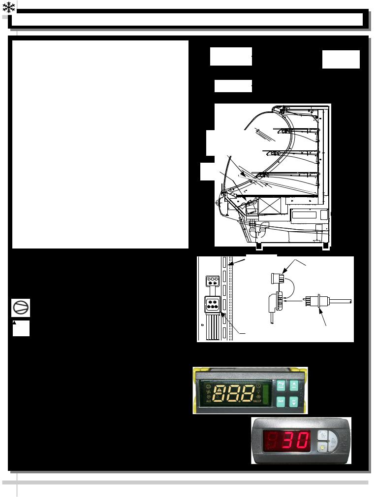
15. Display Case Start-Up
A. Case
Turn main power on at case rear.
From the front of the case, lift deck to check that the coil fans are functioning properly.
Coil fans, (and in self-contained units, the compressor motor) should turn on.
B. Lights
Turn lights on.
Self-Contained units: Switch at rear.
Remote cases: NO SWITCH (lights come on when main power switch is turned on).
All lights should come on at the same time. First time lighting may require a short warm-up period for the bulbs.
Slightly dim / flickering of new bulbs is normal. If lights do not turn on, check raceway plugs.
Lighting is wired in series so all lights must be plugged in or receptacles capped for case lights to be on. See illustration at right.
LED Lights: If lights do not come on, check that plug is properly inserted into socket.
C. Temperature Controller (All Self-Contained Units and some Remote Units)
Check that compressor symbol light is on.Depending upon SCC-Supplied temperature
controller, compressor is identified with either:
Compressor symbol (common in Carel® temperature controllers).
Snowflake symbol (common in CPC® temperature controllers).
After case has run for a few minutes, check that temperature starts to drop.
If temperature controller does not begin cooling (in a few minutes) see temperature controller section in this operating manual for instructions.
Remote units (without temperature controller on case): Verify that refrigeration requirements listed on serial label (found on the case) are being met.
D. Saturated Suction Temperature (Remote Units)
See serial label on case for suction temperature requirements and BTU requirements.
See serial label on case for defrost schedule and temperature termination parameters.
Temperature |
Main Power |
|
Controller |
||
Switch |
||
|
||
Light Switch |
|
Deck removal |
(for coil fans |
access) |
Coil |
Fans |
Raceway
Cap
|
Plug |
|
Receptacle |
|
|
|
|
|
Raceway Receptacle, Plug and Cap
Sample Carel®
Controller Face
Sample CPC®
Controller Face
10
|
|
|
|
|
|
|
NOTE: BELOW ILLUSTRATIONS MAY |
|
|
|
|
|
|
|
|
|
|
|
|
|
|
|
|
|
|||||
|
DRAIN, HOSE AND BRACKET PLACEMENT ILLUSTRATIONS |
|
|
|
|
NOT EXACTLY REFLECT EVERY |
|
|
|
|
|
|
|
||||||
|
|
|
|
|
PARTICULAR CASE’S FEATURES |
|
|
||
|
|
||||||||
|
|
|
|
|
|
|
|
|
|
|
|
|
|
|
|
|
|
|
|
Three Evaporator Systems Are Illustrated Below:
Illustration #1: Hot Gas “CopeVap” Evaporator System. “Copevap” is built into Compressor Unit.
Illustration #2: Hot Gas Evaporator System.
Illustration 3A/3B : Electrical Heat Rod Evaporator System. Note: Separate Evaporator Pan.
Warning! Regardless of Evaporator, the Hose and Drain Trap MUST BE secured and positioned over Evaporator Pan to prevent water seepage / spillage. When sliding out Condenser Unit, be careful that drain is not pulled from proper position.
Note: Drain |
Bracket |
|
positioned |
|
Hose thru bracket |
directly over |
|
|
Reservoir |
|
|
“CopeVap” |
|
Drain Trap |
|
|
|
Reservoir |
|
Clear PVC |
|
Clamp |
Tube |
1. Hot Gas “CopeVap” Evaporator System.
Use Hose Clamp to Secure Hose to Adapter
2. Hot Gas Evaporator System.
Hot gas serpentine coil is routed through a condensate reservoir allowing water to be heated. This system uses a wicking material (partially submersed) with warm condenser air passing through it for evaporation.
Also incorporates an overflow reservoir with heating element to ensure complete condensate removal.
This area of your unit may widely vary (due to display case options).
Sight Glass
Scroll
Compressor
Suction
Accumulator
Hot
Serpentine
Coil
Receiver
Refrigeration
Assembly
Base
Elec. Box, Hot
Gas Condensate
Overflow
Fan
Shroud
Filter
Drier
Wicking
Material
Compressor Pan Shipment Screw (1 at each side)
Clear PVC
Tube
|
Drain |
Evap. Pan |
Trap |
|
|
Positioning |
Evaporator |
Bracket |
|
|
Pan |
Evaporator Pan |
Drain |
|
Trap |
||
|
||
Evap. Pan Positioning Bracket |
|
3A. Front View of |
3B. Isometric View of |
Electrical Heat Rod Evaporator System |
Electrical Heat Rod Evaporator System |
|
|
11
 Loading...