


READ AND SAVE THESE INSTRUCTIONS
INSTALLATION & OPERATING MANUAL
PN 54380
COMBINATION CASES
•CONVERTIBLE SERVICE ABOVE REFRIGERATED SELF-SERVICE (HOU[L*]52R)
•NON-REFRIGERATED SERVICE ABOVE REFRIGERATED SELF-SERVICE (HUDLR[L*]52)
•REFRIGERATED SERVICE ABOVE REFRIGERATED SELF-SERVICE (HURLR[L*]52)
•NON-REFRIGERATED SERVICE BESIDE REFRIGERATED SELF-SERVICE (HVLD[L*]RSS)
•REFRIGERATED SERVICE BESIDE NON-REFRIGERATED SERVICE (H5C[L*]50LR or RR)
•NON-REFRIGERATED SERVICE ABOVE REFRIGERATED SERVICE (HSL[L*]50R)
•REFRIGERATED SERVICE ABOVE REFRIGERATED SELF-SERVICE WITH REAR STORAGE (HVOU[L*]RSS)
PLEASE NOTE THE FOLLOWING:
1.YOUR SPECIFIC MODEL NUMBER IS ON THE SERIAL LABEL ON CASE REAR (NEAR MAIN POWER SWITCH).
2.CASES SHOWN REFLECT FULL & OPEN END PANELS / STRAIGHT OR ANGLED BASES. YOURS MAY DIFFER.
3.SEE “MODELS (AND THEIR RESPECTIVE CASE DIMENSIONS) LISTED IN THIS MANUAL” SECTION FOR ADDITIONAL INFORMATION REGARDING SPECIFIC CASE DIMENSIONS OF STANDARD MODELS AND CDRs.
4.*[L] DENOTES VARIETY OF CASE LENGTHS.
HOU[L*]52R w/Optional |
|
HOU[L*]52R |
HUDLR[L*]52 |
HURLR[L*]52 w/Optional |
|||||||||
|
Lower Display Steps |
|
Optional Angled Base |
||||||||||
|
|
Straight Base |
Lower Display Steps |
||||||||||
|
|
|
|
|
|
|
|
|
|
||||
|
|
|
|
|
|
|
|
|
|
|
|
|
|
|
|
|
|
|
|
|
|
|
|
|
|
|
|
|
|
|
|
|
|
|
|
|
|
|
|
|
|
HVLD[L*]RSS With |
H5C[L*]50LR or RR |
HSL[L*]50R |
HVOU[L*]RSS |
Straight Base |
Straight Base / Cutaway Ends |
Optional Lower Shelf |
Straight Base |
Structural Concepts Corporation · 888 E. Porter Road · Muskegon, MI 49441 Phone: 231.798.8888 Fax: 231.798.4960 · www.structuralconcepts.com
I:\Oper Manual\Standard\Encore_Combo_Case_Oper_Manual_54382.pub |
Rev A Date: 6.18.2009 |

TABLE OF CONTENTS
|
TABLE OF CONTENTS ……………………………………………………………………………………... |
|
2 |
|
|
|
|
|
|
||
|
MODELS LISTED IN MANUAL / DETERMINING THEIR RESPECTIVE CASE DIMENSIONS…….. |
|
3 |
|
|
|
OVERVIEW AND WARNINGS ……………..…….…………………………..………………………...….. |
|
4 |
|
|
|
INSTALLATION: REMOVAL FROM SKID, REMOVING LOWER FRONT PANELS ..……...…….….. |
|
5 |
|
|
|
INSTALLATION: ADJUSTING FRONT PANELS / ADJOINING UNITS / GLASS SHELVING ………. |
|
6 |
|
|
|
INSTALLATION: ELEC. CONNECTIONS / LOCKING CASTERS / ADJUSTING LEVELERS ……… |
|
7 |
|
|
|
INSTALLATION: FRONT GLASS ALIGNMENT & ADJUSTMENT (CURVED & FLAT) ……………... |
|
8 |
|
|
|
INSTALLATION: REFRIG. LINES / STUB-UPS / DRAINS / WIRING DIAGRAMS / VENTILATION .. |
|
9 |
|
|
|
INSTALLATION: DISPLAY CASE START-UP / REAR STORAGE (MODEL HVOU[L]RSS ONLY) ... |
|
10 |
|
|
|
INSTALLATION: DISPLAY CASE START-UP, LIGHTS, TEMPERATURE CONTROLLER, SST …. |
|
11 |
|
|
|
BAFFLES: AMBIENT VS. REFRIGERATED CONDITIONS ……………………………………………. |
|
12 |
|
|
|
OPTIONAL NIGHT AIR CURTAIN INST. / OPER. INSTRUCTIONS (HUDLR / HURLR / HOU) …... |
|
13 |
|
|
|
OPTIONAL NIGHT AIR CURTAIN INST. & OPERATING INSTRUCTIONS (MODEL HVLD[L]RSS). |
|
14 |
|
|
|
SECURITY GRID INSTRUCTIONS (OPTIONAL) ………………………………………………………... |
|
15-16 |
|
|
|
SECURITY GRID INFORMATION FOR MODEL HVLD[L]RSS ONLY…………………………………. |
|
17 |
|
|
|
DRAIN, HOSE AND BRACKET PLACEMENT ILLUSTRATIONS …………..…………..……….…….. |
|
18 |
|
|
|
MAINTENANCE FUNDAMENTALS - STANDARD LIGHT FIXTURES / REAR SLIDING DOORS.... |
|
19 |
|
|
|
MAINTENANCE FUNDAMENTALS - LED LIGHTS/BRACKETS/SHELVES/DRAIN/TXV VALVE …. |
|
20 |
|
|
|
MAINTENANCE FUNDAMENTALS - REFRIG. PKG., TEMP. CONTROLLER, EVAP. PAN ……….. |
|
21 |
|
|
|
MAINTENANCE FUNDAMENTALS - HONEYCOMB AIR DIFFUSERS/UPPER SECTION AIR DUCT |
|
22 |
|
|
|
CLEANING SCHEDULE ………………………………………………………………..…………....…….. |
|
23 |
|
|
|
TROUBLESHOOTING - GENERAL ISSUES ………………………………………..…………...………. |
|
24-26 |
|
|
|
TROUBLESHOOTING - CONDENSING SYSTEM ………………………………..……………..…..….. |
|
27 |
|
|
|
TROUBLESHOOTING - EVAPORATOR SYSTEM ………………………………..……………..……... |
|
28 |
|
|
|
PREVENTIVE MAINTENANCE (TO BE PERFORMED BY TRAINED SERVICE PROVIDER) …..... |
|
29 |
|
|
|
SERIAL LABEL INFORMATION & LOCATION ..……………………………………...…....…………..… |
|
30 |
|
|
|
TEMPERATURE CONTROLLER - CAREL® ...…. ……………………..……..…………………...…….. |
|
31-33 |
|
|
|
TEMPERATURE CONTROLLER - CPC® .……………………………………………………………….. |
|
34-35 |
|
|
|
TECHNICAL SERVICE CONTACT INFORMATION & WARRANTY INFORMATION ...……….…..... |
|
36 |
|
|
|
|
|
|
|
|
|
|
|
|
|
|
2

MODELS LISTED IN THIS MANUAL / DETERMINING THEIR RESPECTIVE CASE DIMENSIONS
DETERMINING YOUR MODEL AND ITS CASE DIMENSIONS:
Note 1. Your model number can be found on serial label at rear of case (near main power switch). Note 2. Dimensions of most models can be found at www.structuralconcepts.com. Simply enter the case model number into the Product Number Search box. Click the product specification link for complete dimensions.
Note 3. If your specific model is not found, contact technical service (phone number is listed at Technical Service section in this manual) for dimensions.
Note 4. CDRs (Customer Design Requests) are listed with a 4-digit number. All CDR dimensions are identical to standard model dimensions.
THIS OPERATING MANUAL ENCOMPASSES THE FOLLOWING MODELS (AND THEIR RESPECTIVE CDRs):
|
Model HOU3852R |
|
|
|
|
|
|
|
|
|
|
|
|
|
|
|
|
|
|
|
||||||
|
|
|
|
|
|
Model HUDLR3852 |
|
|
|
|
|
Model HVOU56RSS |
|
|
|
|
||||||||||
|
|
|
|
|
|
|
|
|
|
|
|
|
|
|
||||||||||||
|
Model HOU4852R |
|
|
|
|
|
Model HUDLR4852 |
|
|
|
|
|
|
|
|
|
||||||||||
|
|
|
|
|
|
|
|
|
|
|
Model HVOU74RSS |
|
|
|
|
|||||||||||
|
Model HOU5652R |
|
|
|
|
|
Model HUDLR5652 |
|
|
|
|
|
|
|
|
|
||||||||||
|
|
|
|
|
|
|
|
|
|
|
Model HVOU96RSS |
|
|
|
|
|||||||||||
|
Model HOU7452R |
|
|
|
|
|
Model HUDLR7452 |
|
|
|
|
|
|
|
|
|
||||||||||
|
|
|
|
|
|
|
|
|
|
|
Model HVOU144RSS |
|
|
|
|
|||||||||||
|
Model HOU9652R |
|
|
|
|
|
|
|
|
|
|
|
|
|
|
|
|
|
|
|||||||
|
|
|
|
|
|
|
|
|
|
|
|
|
|
|
|
|
|
|
|
|||||||
|
Model HOU9652R.4419 |
|
|
|
|
|
|
|
|
|
|
|
|
|
|
|
|
|
|
|
||||||
|
|
|
|
|
|
|
|
|
|
|
|
|
|
|
|
|
|
|
|
|||||||
|
|
|
|
|
|
|
|
|
|
|
|
|
|
|
|
|
|
|
|
|||||||
|
Model HOU9652R.4419A |
|
|
|
|
|
|
|
|
|
|
|
|
|
|
|
|
|
|
|
||||||
|
|
|
|
|
|
|
|
|
|
|
|
|
|
|
|
|
|
|
|
|
|
|
|
|
|
|
|
|
|
|
|
|
|
|
|
|
|
|
|
|
|
|
|
|
|
|
|
|
|
|
|
|
|
|
|
|
|
|
|
|
|
|
|
|
|
|
|
|
|
|
|
|
|
|
|
|
|
|
|
|
|
|
Model H5C4850LR |
|
|
|
|
|
|
|
|
|
|
|
|
|
|
Model HVOU96RSS.3580B |
|
|
|||||||
|
|
|
|
|
|
|
|
|
|
|
|
|
|
|
|
|
|
|||||||||
|
|
|
|
|
|
|
Model HURLR3852 |
|
|
|
|
|
|
|
|
|||||||||||
|
|
Model H5C4850RR |
|
|
|
|
|
Model HURLR4852 |
|
|
|
|
Model HVOU96RSS.3615A |
|
|
|||||||||||
|
|
Model H5C5650LR |
|
|
|
|
|
Model HURLR5652 |
|
|
|
|
Model HVOU96RSS.4260 |
|
|
|||||||||||
|
|
Model H5C5650RR |
|
|
|
|
|
Model HURLR7452 |
|
|
|
|
Model HVOU144RSS.3580C |
|
|
|||||||||||
|
|
Model H5C7450LR |
|
|
|
|
|
|
|
|
|
|
|
|
|
|
Model HVOU96RSS.3580D |
|
|
|||||||
|
|
Model H5C7450RR |
|
|
|
|
|
|
|
|
|
|
|
|
|
|
Model HVOU144RSS.3580E |
|
|
|||||||
|
|
|
|
|
|
|
|
|
|
|
|
|
|
|
|
|
|
|
|
Model HVOU144RSS.4261 |
|
|
||||
|
|
|
|
|
|
|
|
|
|
|
Model HVLD48RSS |
|
|
|
|
|
|
|
||||||||
|
|
|
|
|
|
|
|
|
|
|
|
|
|
|
|
|
|
|||||||||
|
|
|
|
|
|
|
|
|
|
|
|
|
|
|
|
|
|
|
|
|
|
|
|
|||
|
|
|
|
|
|
|
|
|
|
|
Model HVLD56RSS |
|
|
|
|
|
|
|
|
|
|
|
|
|
||
|
|
Model HSL3850R |
|
|
|
|
|
|
|
|
|
|
|
|
|
|
|
|
|
|
|
|||||
|
|
|
|
|
|
|
|
|
|
|
|
|
|
|
||||||||||||
|
|
|
|
|
|
|
|
Model HVLD74RSS |
|
|
|
|
|
|
|
|
|
|
|
|
|
|||||
|
|
Model HSL4850R |
|
|
|
|
|
|
|
|
|
|
|
|
|
|
|
|
|
|
|
|||||
|
|
|
|
|
|
|
|
|
|
|
|
|
|
|
|
|
|
|
|
|
|
|
|
|
|
|
|
|
|
|
|
|
|
|
|
|
|
|
|
|
|
|
|
|
|
|
|
|
|
|
|
|
|
|
|
|
|
|
|
|
|
|
|
|
|
|
|
|
|
|
|
|
|
|
|
|
|
|
|
|
|
|
|
|
|
|
|
|
|
|
|
|
|
|
|
|
|
|
|
|
|
|
|
|
|
|
|
OVERVIEW AND WARNINGS
OVERVIEW
•These Structural Concepts Encore® service cases are designed to merchandise product at 5°C / 41°F or less product temperatures.
•These cases should be installed and operated according to this operating manual’s instructions to insure proper performance. Improper use will void warranty.
This unit is designed for the display of products in ambient store conditions where temperatures and humidity are maintained within a specific range.
•For NSF® Type 1 Conditions (most cases): ambient conditions are to be at 55% max. humidity / 75°F.
•For NSF® Type 2 Conditions: ambient conditions are to be at 60% maximum humidity / 80°F.
•If unsure if your case is Type 1 or Type 2, contact Structural Concepts Technical Service (see Technical Service section in this manual for phone number).
Caution: Do not allow air conditioning, electric fans, open doors or windows to create air currents around display case as this may detrimentally affect proper case temperatures and operation.
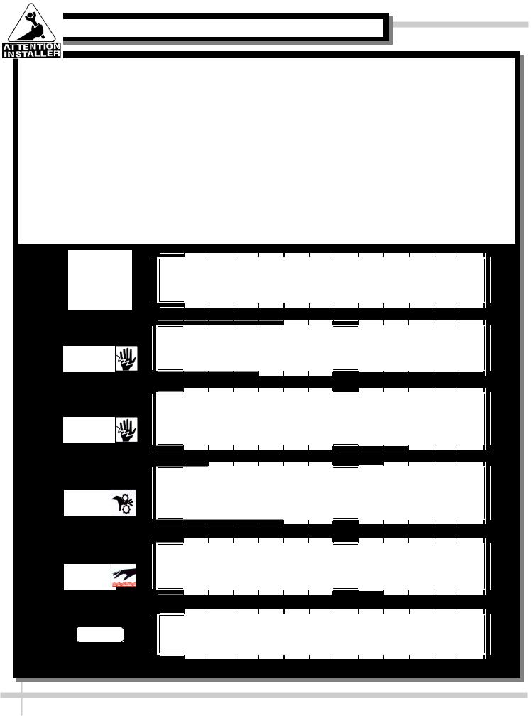
ATTENTION INSTALLER
This equipment must be installed in compliance with all applicable NEC, federal, state and local plumbing codes.
WARNING |
WARNING |
|
ELECTRICAL |
Risk of electric shock. |
|
Disconnect power before servicing unit |
||
HAZARD |
WARNING
ELECTRICAL
HAZARD
WARNING
KEEP HANDS
CLEAR
WARNING
HOT
SURFACE
CAUTION
WARNING
More than one source of electrical supply is employed with units that have separate circuits.
Disconnect all sources before servicing.
WARNING
Hazardous moving parts. Do not operate unit with covers removed. Fan blades may be exposed when deck panel is removed.
Disconnect power before removing deck panel.
WARNING
Evaporator Pan is Hot! Disconnect and allow to cool before cleaning or removing from case.
CAUTION
Lamps have been treated to resist breakage and must be replaced with similarly treated lamps.
4

INSTALLATION: REMOVAL FROM SKID, REMOVING LOWER FRONT PANELS
1. Remove Case From Skid (Levelers)
•Remove shipping brace that may be securing case to skid.
•Support case to prevent tipping.
•Caution! Levelers can be damaged if case hits floor with heavy force!
•Carefully slide unit to rear of skid and tip backward off skid.
•Illustration may not reflect every feature or option of your particular case.
Slide Skid Out
Case can be repositioned with pallet truck when front lower panel is removed. Blocking may be necessary to obtain adequate height.
2. Remove Case From Skid (Casters)
Remove shipping brackets that may be securing casters to skid
•Place ramp up against skid (to allow case to smoothly slide off from skid).
•Maintain support of case at all times or center of gravity may cause case to fall.
•Unlock Casters. Roll unit to rear of skid.
Roll down ramp and off from skid.
Note: Illustrations |
|
|
shown reflect a |
Support |
|
general outline of |
||
while |
||
sample cases and do |
||
rolling |
||
not reflect features or |
||
case |
||
options of your |
||
down |
||
particular model. |
ramp. |
Ramp |
3A. Removing Angled Lower Front Panels
Upper panel support.
•Remove screws located behind upper
front panel. Lower panel support.
•Most applications, screws secure the lower panel support (located below front panel) to the unit.
See illustration at right.
3B. Removing Vertical Lower Front Panels
Upper
Panel 
Support
Angled
Lower
Front 
Panel
Remove screws. Lift out.
Front Panel Upper Support |
|
Lower Panel |
• Lift Front Glass. |
*Apply Upward Pressure |
Support |
• Remove the caps and screws holding |
|
|
Deck Support in place. |
Front Glass |
Deck |
Front Panel Lower Support |
|
Support |
|
|
|
• For most display cases, screws secure |
|
|
Front Panel Lower Support to Base. |
Front Panel |
|
• Remove screws holding Front Panel |
Upper Support |
Typical |
Lower Support to Display Case Base. |
|
Side |
Vertical Lower Front Panel can now be removed (see |
Vertical Lower |
Panel |
illustration at lower right). |
Front Panel |
|
*Alternate applications (for cases without lower panel |
|
Display |
screws): Apply upward pressure to lower panel |
|
|
|
Case |
|
support to disengage lower support panel tabs from |
Front Panel |
Base |
slots located in the base at both ends of the unit. |
Lower Support |
|
5

INSTALLATION: ADJUSTING FRONT PANELS / ADJOINING UNITS / GLASS SHELVING
4. Adjusting Upper Front Panels |
|
|
|
|
|
|
|
|
|
|
|
|
|
|
|
|
|
|
|
|
|
|
Remove Screw |
|
|
|
|
|
|
|
|
|
|
|
|
|
|
|
|
|
|
|
IN / OUT |
||
• Remove screw cover and loosen adjustment |
|
|
|
|
|
|
|
|
|
|
|
|
|
|
|
|||||||
Cover Cap |
|
|
|
|
|
|
|
|
|
|
|
|
|
|
|
|
||||||
|
|
|
|
|
|
|
|
|
|
|
|
|
|
|
||||||||
screws. |
|
|
|
|
|
|
|
|
|
|
|
|
|
|
|
|
|
|
|
|
|
|
|
|
|
|
|
|
|
|
|
|
|
|
|
|
|
|
|
|
|
|
|
||
|
|
|
|
|
|
|
|
|
|
|
|
|
|
|
|
|
|
|
|
|
||
• Adjust alignment and tighten screws. |
|
|
|
|
|
|
|
|
|
|
|
|
|
|
|
|
|
|
|
|
UP |
|
• See illustration at mid-right. |
|
|
|
|
|
|
|
|
|
|
|
|
|
|
|
|
|
|
|
|
or |
|
|
|
Loosen |
|
|
|
|
|
|
|
|
||||||||||||
5. Bolting and Caulking Units Together |
|
Adjustment |
|
|
|
|
|
|
|
|
|
|
|
|
|
|
|
|
|
|
DOWN |
|
|
|
|
|
|
|
|
|
|
|
|
|
|
|
|
|
|
|
|||||
|
Screws |
|
|
|
|
|
|
|
|
|
|
|
|
|
|
|
|
|
|
|
||
|
|
|
|
|
|
|
|
|
||||||||||||||
|
|
|
|
|
|
|
||||||||||||||||
Follow these steps to assure a secure, level lineup.
A. |
Begin all lineups leveling from highest point of |
|
|
|
|
|
|
floor. |
|
|
|
|
|
B. |
After the ’first’ case is level, apply industrial grade |
|
|
|
|
|
|
butyl caulk on non-visible areas (at case end). |
|
Upper |
|
|
|
|
Use industrial grade silicone sealant on visible |
|
Front |
|
|
|
|
areas (at case end). |
|
Panel |
|
|
|
C. Form Two (2) Caulk/Sealant Lines: (Sanitation |
|
|
|
|
IN / OUT |
|
|
and Refrigeration). See illustration at mid-right for |
|
|
|
|
|
|
outline of caulk/sealant lines. |
Approximate hole |
Sanitation Bead |
Refrigeration Bead |
||
D. Line up ‘second’ case bolt-hole to bolt-hole to |
||||||
|
‘first’ case. |
locations pointed |
|
|
|
|
E. |
Using SCC-supplied bolts (found in installation |
|
at with arrows |
|
|
|
( |
) for bolting |
|
|
|
||
|
packet), insert bolts in bolt hole locations (shown |
|
|
|
||
|
units together. |
|
|
|
||
|
at right). You may need to remove decking to |
|
|
|
||
|
|
|
|
|
|
|
|
access lower bolt holes. |
|
|
|
|
|
F. |
Caution! Front of cases MUST be flush with each |
|
|
Deck |
Sanitation |
|
|
other! After leveling, all cases to be same height. |
|
|
Bead |
||
|
|
|
|
|||
G. Using SCC-supplied nuts & bolts, lightly tighten |
|
|
|
|
|
|
|
each of the 5 to 8 bolts in a cross-wise pattern. |
|
|
|
|
|
|
Work your way around the pattern, tightening |
|
|
|
|
|
|
more firmly at each pass. Do not firmly tighten |
|
|
|
|
|
|
one bolt and then start on the next! |
|
|
|
|
|
H. After the cases are bolted together, level the |
|
|
|
|
|
|
|
‘second’ case. Repeat this process for each case |
|
|
|
|
|
|
to be adjoined. |
|
|
|
|
Refrigeration |
I. |
After all lined-up cases are level, seal all seams |
|
|
|
|
Bead |
|
with industrial grade silicone sealant. |
|
|
|
|
|
6. Glass Shelving
Glass shelving will be packed separately.
• Caution! Carefully remove from packaging.
• Grasp firmly and carefully install.
• Caution! Check that plastic edging is intact before placing glass shelving onto brackets!
• Plastic edging must NOT be removed from glass
shelves. Contact Structural Concepts for |
|
|
replacement edging (see TECHNICAL |
Glass |
|
SERVICE CONTACT INFORMATION section). |
||
Shelves |
||
• Check that glass shelving is in proper position |
|
|
before placing product in case. |
|
•See illustration at lower-right.
6
INSTALLATION: ELECTRICAL CONNECTIONS / LOCKING CASTERS / ADJUSTING LEVELERS
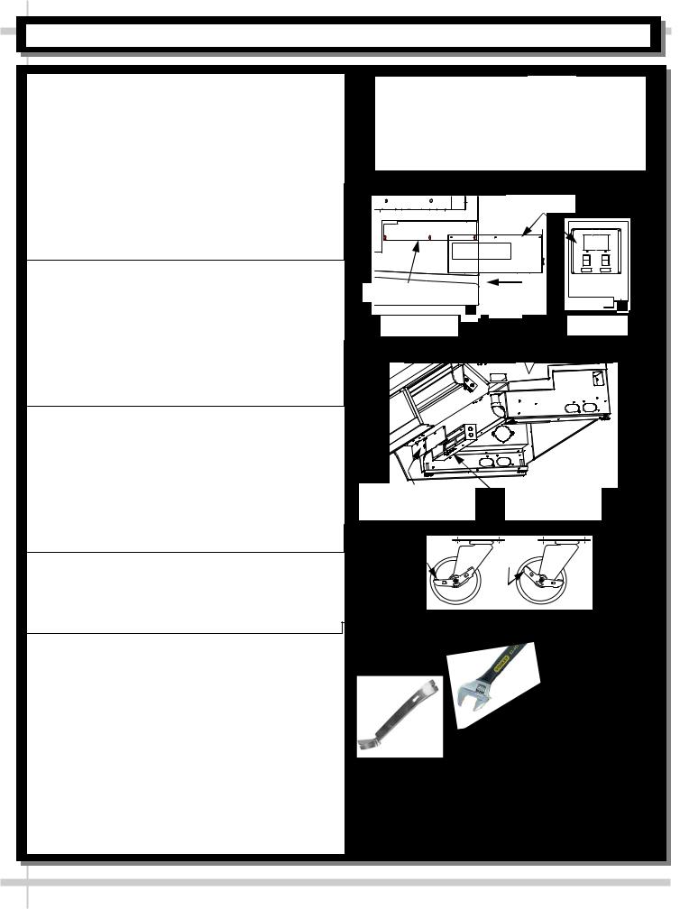
7. Electrical Connections
A. Rear Wire-Ways
•Remove screws from rear wire-way cover to access electrical leads.
•Wiring runs case to case through base cut-outs.
•Knockout is provided in bottom of wire-way for stub-up connection.
•See illustration at top-right.
Note: Wiring process must be performed by certified electricians only.
•Voltage rating is on serial label at case rear.
B. Rear Ballast Box
•Remove 4 screws from ballast box face.
•Remove screws from rear panel (if any).
•Remove 3 screws from inner support.
•Knockouts are located on side and rear of box for making electrical connections.
Note: Wiring process must be performed by certified electricians only.
•Serial label (at case rear) lists voltage rating.
C. Front Ballast Box
•Remove front panel.
•Stub-up connections are in ballast box.
•Remove ballast box covers.
•Knockouts are on sides and front of ballast assembly for making electrical connections.
Note: Wiring process must be performed by certified electrician only.
•Voltage rating is on serial label at case rear.
8. Cases With Casters: Lock and Unlock
•To lock casters, press down on lever.
•To unlock casters, pull lever up.
•See illustration at right.
Ballast
Wireway |
Raceway |
|
Cover |
|
Ballast Box |
Inner Support |
Case |
|
Rear |
Side View |
Case Rear |
Front Ballast |
Electrical Leads |
||
Box Covers |
Access |
||
|
|
d |
d |
|
e |
e |
|
|
k |
|
k |
|
c |
|
c |
o |
|
lo |
|
L |
|
|
n |
|
|
|
U |
9. Cases With Levelers: Adjust Levelers
•After case is in position, adjust case so it is level and plumb (see illustration at right).
•You may need to remove front and/or rear Toe-Kick to access levelers.
•Use adjustable wrench (and possibly a pry bar) to adjust leveler.
•Do not use pry bar on toe-kick (it may buckle).
•Do not use pry bar on end panel (it may chip).
•Use pry bar ONLY on base frame to avoid damaging case.
•Use a block to reach base frames with pry bar.
•See illustrations at right.
Adjustable
Wrench
Pry Bar
Block
Base
Frame
Leveler Toe-Kick 
7

INSTALLATION: FRONT GLASS ALIGNMENT & ADJUSTMENT (CURVED & FLAT FRONT GLASS)
10. Front Glass Alignment & Adjustment via Levelers
•Proper alignment of the front glass is important to create and maintain a seal inside the case.
•Improper alignment can cause air leaks compromising the environment inside the case and create condensation.
•Follow the five steps listed below to assure proper front glass alignment.
1. Side-to-Side Leveling: Place level on top of display case (parallel to the front glass). Raise or lower either side of the case by rotating levelers to center the level bubble (following steps 3 and 4 below).
—- Front Glass —-
2. Front-to-Back Leveling:
• Place a level on top of case,
perpendicular to front glass.
• Raise or lower either side of case by rotating levelers to center the level bubble (follow steps 3 and 4).
• Double-check the side-to-side level.
Case with Curved |
ENDPANEL |
|
FRONT |
5. Verification: |
|
Front Glass |
|
||||
|
|
|
|
|
|
|
3. If FRONT-LEFT |
GLASS |
• After adjusting |
||
|
the levelers, |
||||
|
CORNER is too close to |
|
|
open and shut |
|
|
end panel (or hitting it), |
|
|
the front glass. |
|
|
adjust levelers at the |
|
|
• Verify again that |
|
|
BACK LEFT CORNER of |
|
LIFT |
front glass is |
|
|
case DOWNWARD. |
|
properly aligned |
||
|
|
|
|
|
at both left-hand |
|
FRONT |
ENDPANELPANEL |
and right-hand |
||
|
side of case. |
||||
|
GLASS |
|
|
|
• If not, repeat the |
|
4. If FRONT-RIGHT CORNER |
above procedure |
|||
|
|
||||
Case with Flat |
|
is too close to |
end panel (or |
until front glass is |
|
Front Glass |
|
hitting it), adjust levelers at |
properly aligned |
||
|
LIFT |
the BACK RIGHT CORNER |
along both sides |
||
|
of case DOWNWARD. |
of case. |
|||
11. Front Glass Alignment & Adjustment via Clamshell Allen Screw Adjustment
Caution! Glass is extremely heavy! Two people may be required to perform this task.
•Make certain case is level and plumb.
•Lift glass to maximum upright position.
•Determine which side requires realignment.
•While maintaining tight grip on glass, loosen the Allen screws nearest to misaligned side.
•Adjust the glass until properly positioned.
•Allen screws may now be tightened (taunt, but not overly tightened lest glass breakage occur).
•If other side needs alignment, repeat steps while maintaining grip on glass.
|
|
|
|
|
|
|
|
|
|
|
|
|
|
|
|
Lift Handle |
|
|
|
|
|
|
|
|||||||||||||
|
|
|
|
|
|
|
|
|
|
|
|
|
|
|
|
|
|
|
|
|
Clamshell |
|||||||||||||||
|
|
|
|
|
|
|
|
|
|
|
|
|
|
|
|
|
|
|
|
|
||||||||||||||||
|
|
|
|
|
|
|
|
|
|
|
|
|
|
|
|
|
|
|
|
|
||||||||||||||||
|
|
|
|
|
|
|
|
|
|
|
|
|
|
|
|
|
|
|
|
|
|
|
|
|
|
|
|
|
|
|
|
|
|
|
Upper |
|
|
|
|
|
|
|
|
|
|
|
|
|
|
|
|
|
|
|
|
|
|
|
|
|
|
|
|
|
|
|
|
|
|
|
|
||
|
|
|
|
|
|
|
|
|
|
|
|
|
|
|
|
|
|
|
|
|
|
|
|
|
|
|
|
|
|
|
|
|
|
|
|
|
|
|
|
|
|
|
|
|
|
|
|
|
|
|
|
|
|
|
|
|
|
|
|
|
|
|
|
|
|
|
|
|
|
|
|
|
|
|
|
|
|
|
|
|
|
|
|
|
|
|
|
|
|
|
|
|
|
|
|
|
|
|
|
|
|
|
|
|
|
|
|
|
|
|
|
|
|
|
|
|
|
|
|
|
|
|
|
|
|
|
|
|
|
|
|
|
|
|
|
|
|
|
|
|
|
|
|
|
|
|
|
|
|
|
|
|
|
|
|
|
|
|
|
|
|
|
|
|
|
|
|
|
|
|
|
|
|
|
|
|
|
|
|
|
|
|
|
|
|
|
|
|
|
|
|
|
|
|
|
|
|
|
|
|
|
|
|
|
|
|
|
|
|
|
|
|
|
|
|
|
|
|
|
|
|
|
|
|
|
|
|
|
|
|
|
|
|
|
|
|
|
|
|
|
|
|
|
|
|
|
|
|
|
|
|
|
|
|
|
|
|
|
|
|
|
|
|
|
|
|
|
|
|
|
|
|
|
|
|
|
|
|
|
|
|
|
|
|
|
|
|
|
|
|
|
|
|
|
|
|
|
|
|
|
|
|
|
|
|
|
|
|
|
|
|
|
|
|
|
|
|
|
|
|
|
|
|
|
|
|
|
|
|
|
|
|
|
|
|
|
|
|
|
|
|
|
|
|
|
|
|
|
|
|
|
|
|
|
|
|
|
|
|
|
|
|
|
|
|
|
|
|
|
|
|
|
|
|
|
|
|
|
|
|
|
|
|
|
|
|
|
|
|
|
|
|
|
|
|
|
|
|
|
|
|
|
|
|
|
|
|
|
|
|
|
|
|
|
|
|
|
|
|
|
|
|
|
|
|
|
|
|
|
|
|
|
|
|
|
|
|
|
|
|
|
|
|
|
|
|
|
|
|
|
|
|
|
|
|
|
|
|
|
|
|
|
|
|
|
|
|
|
|
|
|
|
|
|
|
|
|
|
|
|
|
|
|
|
|
|
|
|
|
|
|
|
|
|
|
|
|
|
|
|
|
|
|
|
|
|
|
|
|
|
|
|
|
|
|
|
|
Allen |
|
|
|
Clamshell |
|
Screw |
|
Lower |
|
|
|
8
INSTALLATION: REFRIG. LINES / STUB-UPS / DRAINS / WIRING DIAGRAMS / VENTILATION
12. Refrigeration Line Stub-Up Connections
(Remote Units)
•Remove front panel.
•Refrigerant stub-up access opening is at the front on the left hand side of the base (see illustration at top-right).
•Stub-up connections are accessed from inside the case.
•Remove interior ABS decks.
•Remove fan shroud assembly.
•Line connections are in the tub front, on the left hand side
•Remove foam material from the entry hole provided in the tub drain trough.
•Route refrigerant lines through access hole.
•Run case-to-case connections through cutouts in base.
•Sweat the high and low pressure connections.
•Fill access hole with suitable filler to insure watertight integrity of tub.
•Illustration at top-right may not reflect every feature or option of your particular case.
13. Refrigeration Drain Connection
(Remote Units)
•Depending upon drain access needs, either front or rear panel may be removed to gain access to drain stub-up.
•1.5” male PVC stub-up connection is under the case on the right hand side.
•Drain stub-up may be at case center in extended length cases.
•Connect tub drain to floor drain. Maintain 1/4”-fall per foot to provide proper drainage.
•Illustration at top-right may not reflect every feature or option of your particular case.
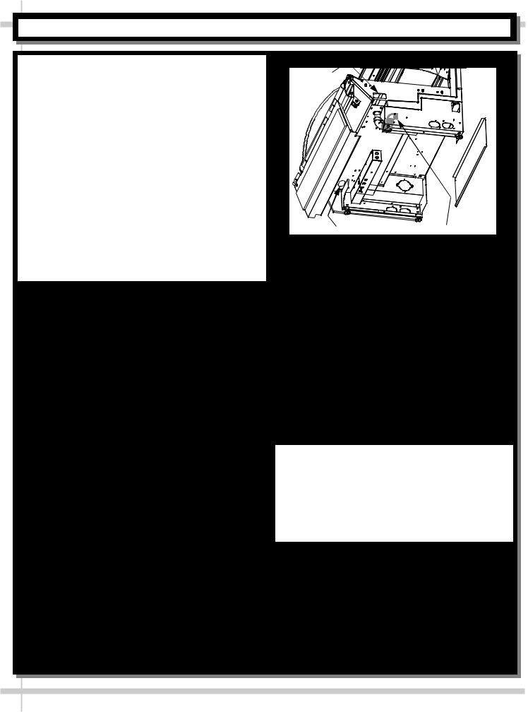
14. Evaporator Pan / Drain Position
(Self-Contained Units)
•Remove the Rear Panel by lifting up & out.
•Slide the Condenser Unit out from case.
•Condenser Unit access is now available.
•Insure that the evaporator pan is installed under the PVC condensate drain trap.
•Insure that the evaporator pan is plugged into the receptacle inside base.
•Lower rear panel back into place.
Cutout
Refrigeration |
|
Drain Stub-Up (may be |
Line Stub-Ups |
|
at case center in |
Access |
|
extended length cases) |
|
|
|
•See Drain, Hose and Bracket Placement section in Operating Manual for details.
15. Electrical Wiring Diagram
•Each case has its own wiring diagram folded and in its own packet.
•Wiring diagram placement may vary; it may be placed near condenser fan cover, ballast box, raceway cover, or other related location.
16. Ventilation and Clearance
•Self-Contained refrigerated cases must maintain airflow clearance of 6” (minimum) to 12” (recommended) at front and rear.
•Restriction of air can void warranty.
•Illustration below may not reflect every feature or option of your particular case.
Check air grilles for obstructions. Maintain airflow clearance of 6” (min.) to 12” (recommended) at front & rear.
9

INSTALLATION: DISPLAY CASE START-UP / REAR STORAGE (MODEL HVOU[L]RSS ONLY)
17. Display Case Start-Up
A. Case |
Rear Doors |
|
• Turn main power on at case rear. |
Raceway Plugs |
• From the front of the case, lift curved front glass |
(See Illustration |
by grasping lift handle and raising (see |
Below) |
|
|
illustration at right). |
Front Panel |
• Lift deck to check that coil fans are running. |
Louvers |
• Coil fans (and in self-contained units, compressor |
|
motor) should turn on. |
|
B. Rear Storage (Model HVOU[L]RSS only) |
|
• Illustration below reflects view of rear storage |
|
area on model HVOU[L]RSS. |
|
• Rear sliding doors provide access to area. |
|
|
Lift Handle |
Rear Storage with |
to Curved |
Acces via Rear |
Front Glass |
Sliding Doors |
|
Model HVOU[L]RSS: Rear Storage with Access via Rear Sliding Doors
Coil Fans
Main Power
Switch
Temperature
Controller 


Light Switch 


Lift Handle |
Deck Removal |
for Coil Fans |
Access |
Rear |
Doors |
Raceway |
Plugs |
10
INSTALLATION: DISPLAY CASE START-UP, LIGHTS, TEMPERATURE CONTROLLER, SST
C. Lights
•Turn lights on.
@Self-Contained units: Switch at rear.
@Remote cases: NO SWITCH (lights come on when main power switch is turned on).
•All lights should come on at the same time. First time lighting may require a short warm-up period.
•Slightly dim / flickering of new bulbs is normal. If lights do not turn on, check raceway plugs.
•Lighting is wired in series so all lights must be plugged in or receptacles capped for case lights to be on. See illustration below right.
•LED Lights: If lights do not come on, check that plug is properly inserted into socket.
D. Temperature Controller (All Self-Contained
Units and some Remote Units)
•Check that compressor symbol light is on.
•Depending upon SCC-Supplied temperature controller, compressor is identified with either:
Compressor symbol (common in Carel® temperature controllers).
Snowflake symbol (common in CPC® temperature controllers).
•After case has run for a few minutes, check that temperature starts to drop.
•If temperature controller does not begin cooling (in a few minutes) see temperature controller section in this operating manual for instructions.
•Remote units (without temperature controller on case): Verify that refrigeration requirements listed on serial label (found on the case) are being met.
E. Saturated Suction Temperature (Remote Units)
•See serial label on case for suction temperature requirements and BTU requirements.
•See serial label on case for defrost schedule and temperature termination parameters.
Raceway
Cap
|
|
Plug |
Receptacle |
|
|
|
|
|
Raceway Receptacle, Plug and Cap
Sample Carel® Controller Face
Sample CPC® Controller Face
11
 Loading...