

Page 1
Audio Effects and VST Instruments
Page 2

Manual by Ludvig Carlson, Anders Nordmark, Roger Wiklander
Quality Control: C. Bachmann, H. Bischoff, S. Pfeifer, C. Schomburg
The information in this document is subject to change without notice and does not represent a commitment on the part of Steinberg Media Technologies GmbH. The software
described by this document is subject to a License Agreement and may not be copied
to other media except as specifically allowed in the License Agreement. No part of this
publication may be copied, reproduced or otherwise transmitted or recorded, for any
purpose, without prior written permission by Steinberg Media Technologies GmbH.
All product and company names are ™ or ® trademarks of their respective owners.
Windows 2000 and Windows XP are trademarks of Microsoft Corporation. The Mac
logo is a trademark used under license. Macintosh and Power Macintosh are registered
trademarks.
© Steinberg Media Technologies GmbH, 2003.
All rights reserved.
Page 3

Table of Contents
Page 4

5 The included effect plug-ins
6 Introduction
7 Delay plug-ins
10 Distortion plug-ins
16 Dynamics plug-ins
37 Filter plug-ins
42 Modulation plug-ins
55 Other plug-ins
67 Reverb plug-ins
69 Surround plug-ins (Cubase SX only)
73 The included VST Instruments
74 A1 Synthesizer
85 VB-1 Bass Synth
87 LM-7 Drum Machine
91 VST plug-ins from previous Cubase versions
92 Introduction
93 Cubase 5 audio effect plug-ins
114 Earlier audio effect plug-ins
123 Cubase 5 VST Instruments
135 Index
CUBASE SX/SL
4 Table of Contents
Page 5

1
The included effect plug-ins
Page 6

Introduction
This chapter contains descriptions of the included plug-in effects and
their parameters.
In Cubase SX/SL, the plug-in effects are arranged in a number of different categories. This chapter is arranged in the same fashion, with
the plug-ins listed in separate sections for each effect category.
CUBASE SX/SL
1 – 6 The included effect plug-ins
Page 7
Delay plug-ins
This section contains descriptions of the plug-ins in the “Delay”
category.
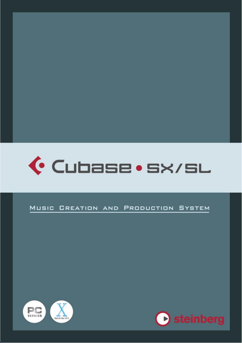
DoubleDelay
This effect provides two separate delays that can be either tempo
based or use freely specified delay time settings. Cubase SX/SL automatically provides the plug-in with the tempo currently used in the
project.
The parameters are as follows:
Parameter Description
Mix Sets the level balance between the dry signal and the effect. If Double-
Delay is used as a send effect, this should be set to maximum (100%)
as you can control the dry/effect balance with the send.
Tempo sync
on/off
Delay Time 1 This is where you specify the base note value for the delay if tempo
Delay Time 2 As above.
Feedback This sets the number of repeats for both delays.
The buttons above the two Delay Time knobs are used to turn tempo
sync on or off for the respective delay. If set to off (the buttons are gray)
the delay time can be set freely with the Delay Time knobs, without
sync to tempo.
sync is on (1/1 - 1/32, straight, triplet or dotted). If tempo sync is off,
it sets the delay time in milliseconds.
Tempo Sync 1 The note value multiplier (x1 to x10) for the first delay unit.
The included effect plug-ins 1 – 7
CUBASE SX/SL
Page 8

Parameter Description
Tempo Sync 2 As above, but for the second delay unit.
Pan1 This sets the stereo position for the first delay.
Pan2 This sets the stereo position for the second delay.
You can also change parameters in the graphic display window. This
works as follows:
•
If tempo sync is on, you can set the Tempo Sync 1 parameter by dragging the light blue handle left and right.
When tempo sync is off, this sets the Delay Time 1 parameter.
•
You can set the Pan 1 parameter by dragging the light blue handle up
and down.
•
The dark blue handle works in the same way but for the corresponding second delay parameters.
CUBASE SX/SL
1 – 8 The included effect plug-ins
Page 9
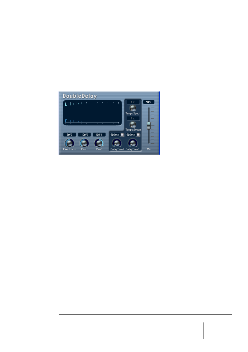
ModDelay
This is a delay effect that can either be tempo-based or use freely specified delay time settings. The delay repeats can also be modulated.
The parameters are as follows:
Parameter Description
Mix Sets the level balance between the dry signal and the effect. If ModDelay
is used as a send effect, this should be set to maximum as you can control the dry/effect balance with the send.
Tempo sync
on/off
Feedback This sets the number of repeats for the delay.
Delay Time This is where you specify the base note value for the delay if tempo sync
Tempo Sync
knob
DelayMod. This controls the pitch modulation rate for the delay effect.
The button above the Delay Time knob is used to turn tempo sync on or
off. If set to off (gray button) the delay time can be set freely with the Delay Time knob, without sync to tempo.
is on (1/1 - 1/32, straight, triplet or dotted). If tempo sync is off, it sets
the delay time in milliseconds.
This is the note value multiplier (x1 to x10) for the delay when tempo
sync is used.
CUBASE SX/SL
The included effect plug-ins 1 – 9
Page 10
Distortion plug-ins
This section contains descriptions of the plug-ins in the “Distortion”
category.
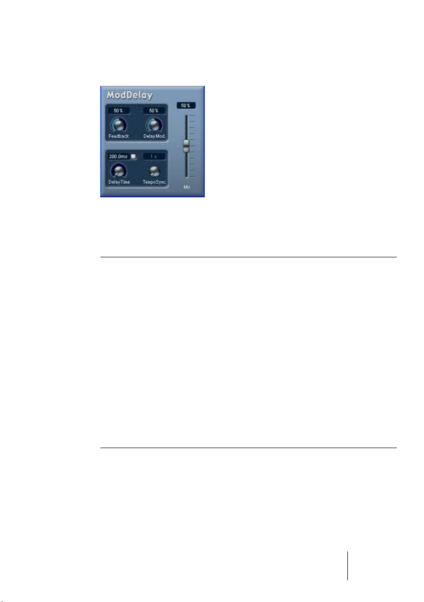
DaTube
This effect emulates the characteristic warm, lush sound of a tube
amplifier.
The parameters are as follows:
Parameter Description
Drive Regulates the pre-gain of the “amplifier”. Use high values if you want an
overdriven sound just on the verge of distortion.
Balance This controls the balance between the signal processed by the Drive pa-
rameter and the dry input signal. For maximum drive effect, set this to its
highest value.
Output Adjusts the post-gain, or output level, of the “amplifier”.
CUBASE SX/SL
1 – 10 The included effect plug-ins
Page 11
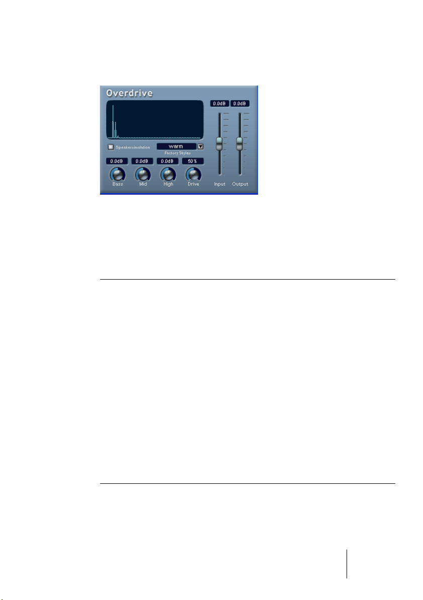
Overdrive
Overdrive is a distortion-type effect, emulating the sound of a guitar
amplifier. A selection of factory styles is available. Note that these are
not stored parameter settings, but different basic overdrive algorithms,
with the style names indicating the basic character of each algorithm.
The parameters are as follows:
Parameter Description
Input Sets the input level.
Output Sets the output level. As overdrive generates harmonics, it increases
the level of the processed signal. You can use the Output fader to compensate for the level increase.
Speaker
simulation
Factory Styles Select one of six presets, which can be used as they are or as a basis
Bass Tone control for the low frequencies.
When this is activated, the effect simulates the sound of a speaker
cabinet.
for further “tweaking”.
Mid Tone control for the mid frequencies.
Hi Tone control for the high frequencies.
Drive Governs the amount of overdrive. You can also adjust this by clicking
and dragging in the display.
CUBASE SX/SL
The included effect plug-ins 1 – 11
Page 12
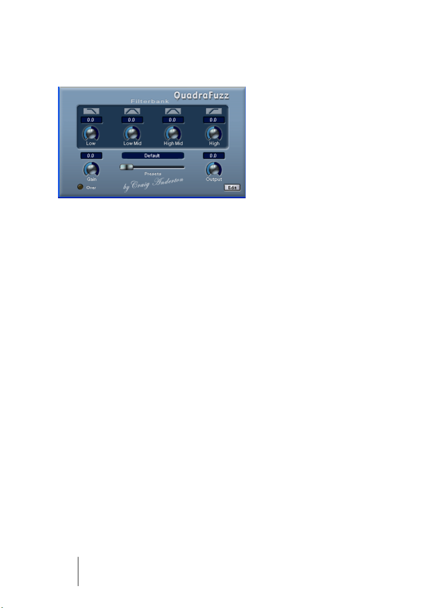
QuadraFuzz
QuadraFuzz is a high-quality distortion effect divided into four frequency
bands allowing for control over the level both before and after distortion.
This high level of control can create a very wide selection of distortion
effects, ranging from subtle to extreme. The user interface consists of
two windows.
•
The main window features four Filterbank controls, the master Gain
and Output controls and a preset selector.
•
In the editor window (which is opened by clicking the “Edit” button in
the lower right corner) the main feature is a frequency band display.
This is where you set the width of the frequency bands as well as their level before distortion.
CUBASE SX/SL
1 – 12 The included effect plug-ins
Page 13
How does QuadraFuzz work?
Here’s a short description of the three major factors that determine how
QuadraFuzz sounds, and where you find the corresponding controls:
• The signal volume control
You can use the Gain control on the left side of the QuadraFuzz main window to control the overall input level of the signal that is fed into the distortion stage. The signal is
split up into four frequency bands in the editor window, with adjustable width and level
controls. These control the input level before distortion.
before
distortion.
• The distortion type, based on a selectable distortion characteristic.
after
• The signal volume control
The Output control on the right side of the QuadraFuzz main window controls the overall output level. In addition, the Filterbank controls in the same window allow you to
raise or lower the output volume of each separate frequency band that was defined in
the editor window.
distortion.
CUBASE SX/SL
The included effect plug-ins 1 – 13
Page 14
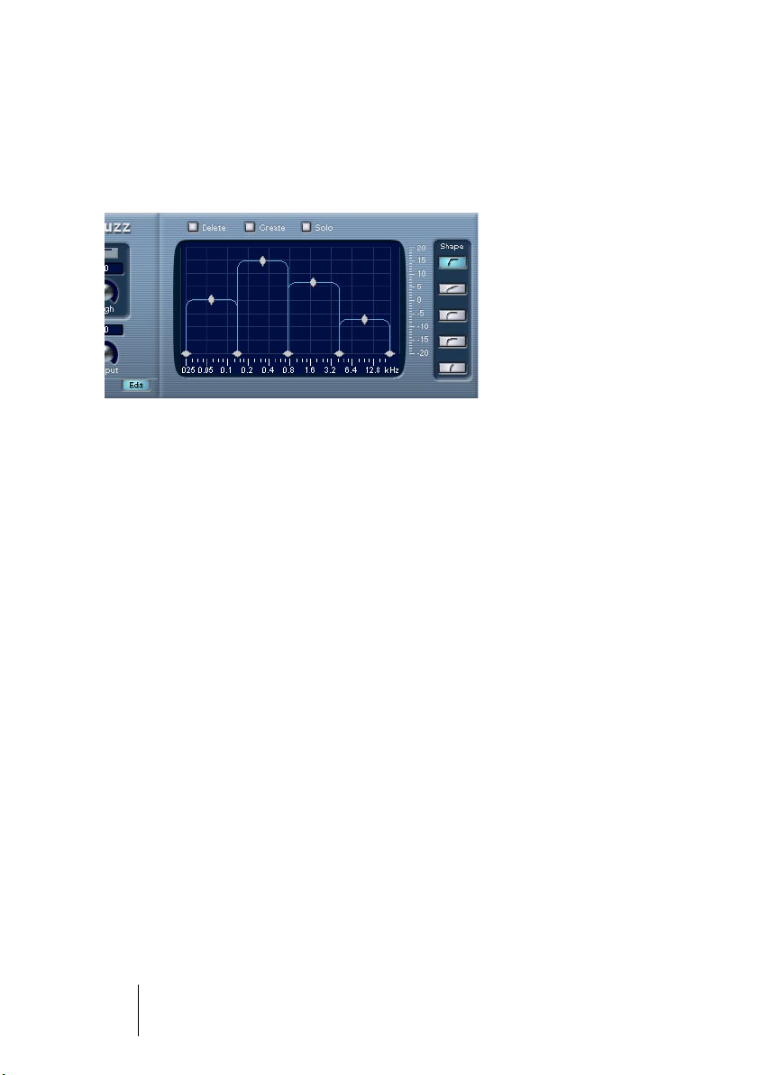
Editing in the frequency band display
The signal is divided into four frequency bands before being passed
to the distortion stage, as explained earlier. You adjust the level and
width of these bands in the frequency band display.
The frequency band display
Two value scales as well as a number of rhomb- and diamond-shaped
handles are available.
• The diamond-shaped handles at the bottom are used to define the corner frequencies of the different frequency bands.
• By using the rhomb-shaped handles on top of each frequency band you determine its relative level before distortion.
• The horizontal value scale below the Frequency band display indicates frequency. The maximum value on this scale corresponds to half the sample rate
of the audio file used (Nyquist theorem).
• The vertical value scale to the right shows the approximate level of an edited
frequency band.
• If you click and hold on one of the handles, its current value is displayed.
Depending on the handle type, corner frequency or level is shown.
• The corner frequency handles can be moved by dragging horizontally. The
level handles can be moved by dragging them up or down.
• To reset a level handle to 0 dB, hold down the [Shift] key on your computer
keyboard and click on the handle.
• If you hold down the [Ctrl]/[Command] key and move a handle, the values will
change in smaller steps.
• The “Solo” button above the frequency band display allows you to monitor
individual frequency bands.
If Solo is activated, one of the four bands is highlighted indicating the selected band.
You select other bands by clicking on them.
CUBASE SX/SL
1 – 14 The included effect plug-ins
Page 15

The parameters
The following tables list all parameters available in QuadraFuzz.
The parameters in the main window are as follows:
Parameter Description
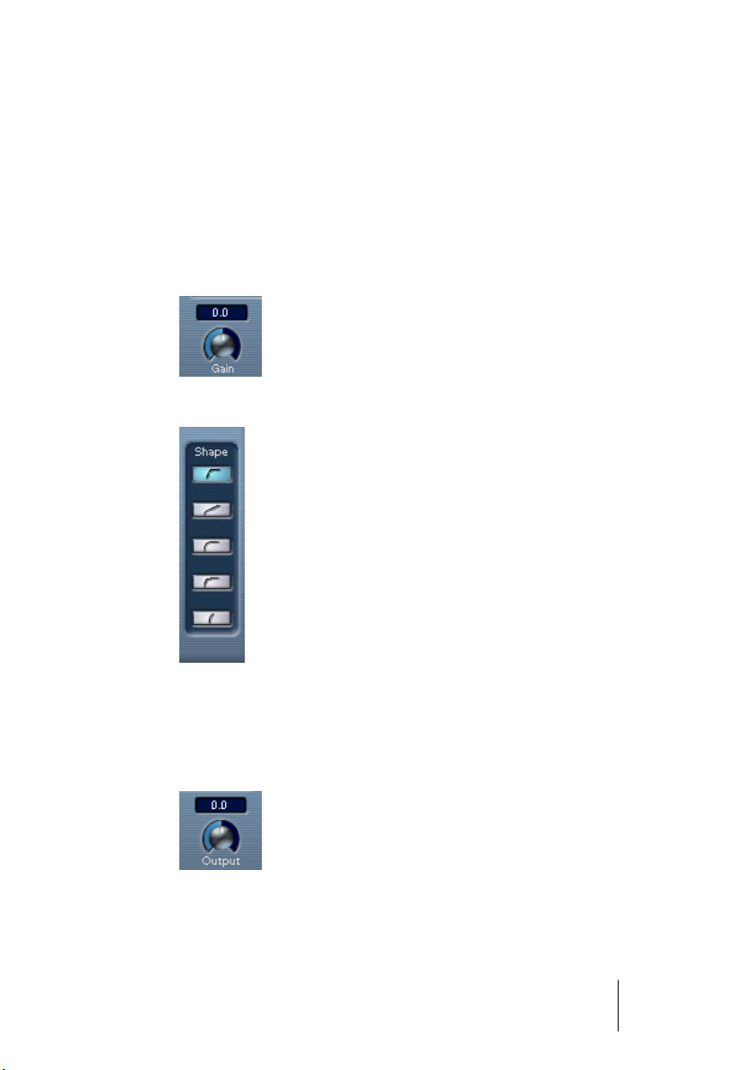
Gain dial This dial can be found in the lower left corner of the QudraFuzz win-
dow. You can use it to control the level of the overall input signal before distortion.
Filterbank dials:
Low/Low Mid/
High Mid/High
Presets fader This is used to select one of the available presets. To select a new
Output dial This controls the overall output level.
Over LED When lit, this indicates that the total input signal level exceeds 0 dB.
Edit button By clicking on this button, located in the lower right corner of the
These dials are used to control the output level of the corresponding
frequency band
for each band.
preset, click on the fader handle and drag horizontally.
This LED does not refer to the output level but solely to the input level
before distortion.
Levels above 0 dB are subject to strict limiting and cause signal clipping. As this is sometimes what you want, QuadraFuzz also offers this
option.
main window, you can open or close the editor window.
after
distortion. Values between +/- 12 dB can be set
The parameters in the editor window are as follows:
Parameter Description
Create If you click on this button, a dialog will open where you can add (and
name) a new preset to the preset set currently in memory. The presets are stored with the project – to make a preset available in other
projects you use the File pop-up menu as usual.
Delete This deletes the selected preset from the preset set currently in mem-
ory. If you click on the button, a dialog appears where you can confirm
or cancel the action.
Solo This mutes all frequency bands except the selected band.
Shape buttons The available distortion characteristics (from bottom to top) create ef-
fects from a slight distortion up to a trashy hardcore sound.
Frequency band
display
Here you control the level and bandwidth for the four bands, see
above.
CUBASE SX/SL
The included effect plug-ins 1 – 15
Page 16
Dynamics plug-ins
This section contains descriptions of the plug-ins in the “Dynamics”
category.
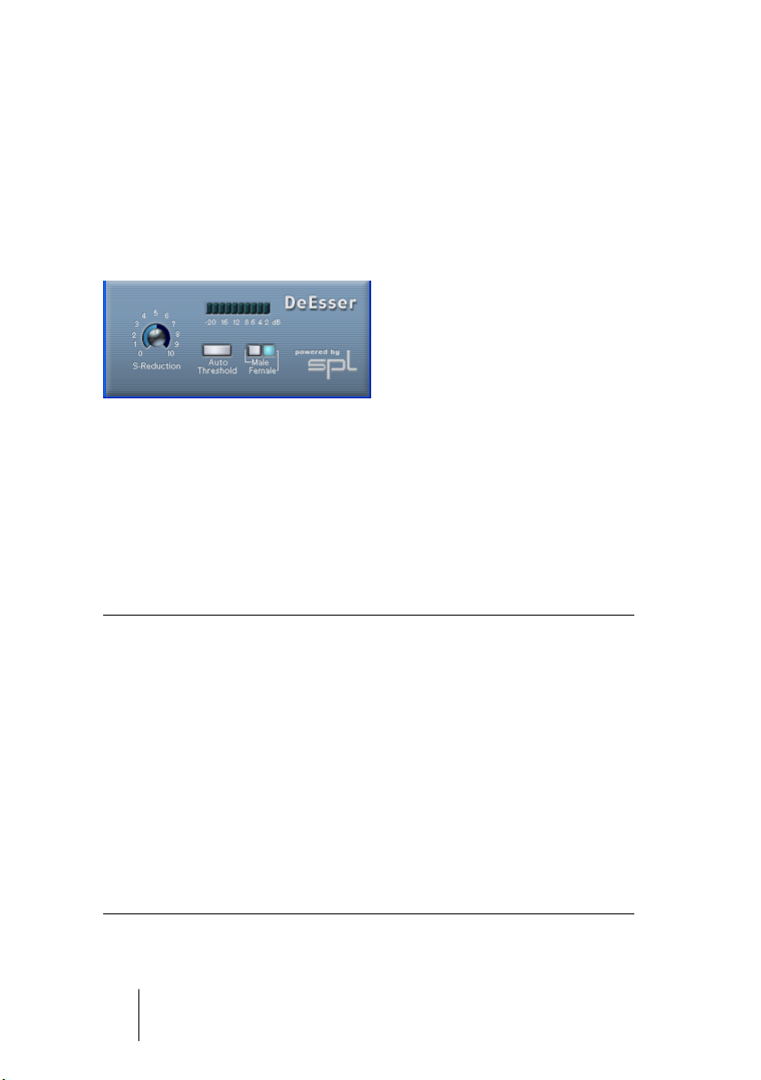
SPL DeEsser (Cubase SX only)
A de-esser is used to reduce excessive sibilance, primarily for vocal
recordings. Basically, it is a special type of compressor that is tuned
to be sensitive to the frequencies produced by the "s" sound, hence
the name de-esser. Close proximity microphone placement and equalizing can lead to situations where the overall sound is just right, but
there is a problem with sibilants. Conventional compression and/or
equalizing will not easily solve this problem, but a de-esser can.
The SPL DeEsser has the following parameters:
Parameter Description
S-Reduction Controls the intensity of the de-essing effect. We recommend that
you start with a value between 4 and 7.
Level display Indicates the dB value by which the level of the sibilant or
s-frequency is reduced. The display shows values between 0 dB (no
reduction) and minus 20 dB (the s-frequency level is lowered by 20
dB). Each segment in the display represents a level reduction of 2 dB.
Auto Threshold See separate description below.
Male/Female This sets the s-frequency and sibilant recognition to the characteristic
frequency ranges of the female or male voice. The center frequency
of the bandwidth at which the SPL DeEsser operates is located in the
7 kHz range for the female voice and in the 6 kHz range for the male
voice.
CUBASE SX/SL
1 – 16 The included effect plug-ins
Page 17

About the Auto Threshold function
Conventional de-essing devices all have a threshold parameter. This is
used to set a threshold for the incoming signal level, above which the
device starts to process the signal. The SPL DeEsser however has
been designed for utmost ease-of-use. With Auto Threshold on (the
button is blue) it automatically and constantly readjusts the threshold
to achieve an optimum result. If you still wish to determine for yourself
at which signal level the SPL DeEsser should start to process the signal, deactivate the Auto Threshold button. The SPL DeEsser will then
use a fixed threshold.
When recording a voice, usually the de-esser's position in the signal
chain is located after the microphone pre-amp and before a compressor/limiter. This is useful, as it keeps the compressor/limiter from unnecessarily limiting the overall signal dynamics by reacting to excessive
sibilants and s-frequencies.
The Auto Threshold function keeps the processing on a constant level.
The input threshold value is automatically and constantly adjusted to
the audio input level. Even level differences of say 20 dB do not have
a negative impact on the result of the processing. The input levels may
vary, but processing remains constant.
CUBASE SX/SL
The included effect plug-ins 1 – 17
Page 18
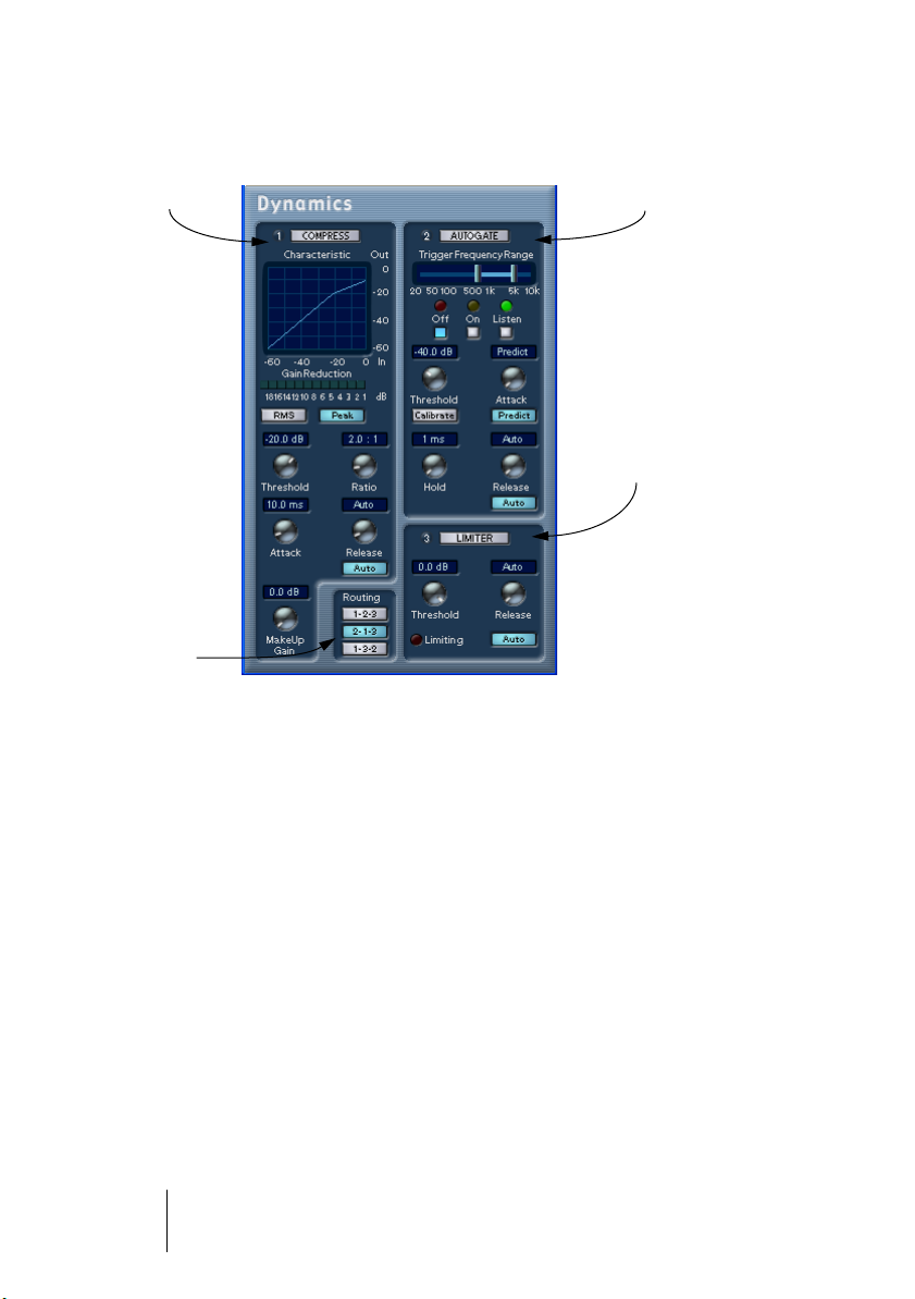
Dynamics
Compressor
Routing
selector
AutoGate
Limiter
Dynamics is an advanced dynamics processor. It combines three separate processors: AutoGate, Compressor and Limiter, covering a variety of dynamic processing functions. The window is divided into three
sections, containing controls and meters for each processor.
Activating the individual processors
You activate the individual processors by clicking on their labels. Activated processors have highlighted labels.
CUBASE SX/SL
1 – 18 The included effect plug-ins
Page 19

The AutoGate section
Gating, or noise gating, is a method of dynamic processing that silences audio signals below a certain set threshold level. As soon as the
signal level exceeds the set threshold, the gate opens to let the signal
through. AutoGate offers all the features of a standard noise gate, plus
some very useful additional features, such as auto-calibration of the
threshold setting, a look-ahead predict function, and frequency selective triggering.
The available parameters are as follows:
Parameter Values Description
Threshold -60 - 0dB This setting determines the level where AutoGate
is activated. Signal levels above the set threshold
trigger the gate to open, and signal levels below
the set threshold will close the gate.
Attack 0,1 -100 ms or
“Predict mode”
Hold 0 - 1000 ms This determines how long the gate stays open af-
Release 10 - 1000 ms or
“Auto”
This parameter sets the time it takes for the gate
to open after being triggered. If the Predict button is activated, it will ensure that the gate will already be open when a signal above the threshold
level is played back. AutoGate manages this by
“looking ahead” in the audio material, checking
for signals loud enough to pass the gate.
ter the signal drops below the threshold level.
This parameter sets the amount of time it takes
for the gate to close (after the set hold time). If
the “Auto” button is activated, AutoGate will find
an optimal release setting, depending on the audio program material.
CUBASE SX/SL
The included effect plug-ins 1 – 19
Page 20
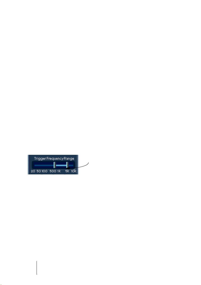
Trigger Frequency Range
AutoGate has a feature that allows the gate to be triggered only by
signals within a specified frequency range. This is a most useful feature because it lets you filter out parts of the signal that might otherwise trigger the gate in places you don’t want it to, thus allowing more
control over the gate function. The Trigger Frequency Range function
is set using the control in the upper part of the AutoGate panel, and
the buttons located below it.
The basic operation of the Trigger Frequency Range function is as
follows:
1.
While playing back audio, click the “Listen” button.
You will now monitor the audio signal, and the gate will be bypassed.
2.
While listening, drag the two handles in the Trigger Frequency Range
display to set the frequency range you want to use to trigger the gate.
You will hear the audio being filtered as you move the handles.
• Dragging the left handle to the right will progressively cut frequencies starting
from the low end of the frequency spectrum.
• Dragging the right handle to the left will progressively cut frequencies starting
from the high end of the frequency spectrum.
The frequency range between the two handles will
be used to trigger the gate.
3.
After setting the frequency range, click the “On” button.
AutoGate will now use the selected frequency range as the trigger input.
4.
To disable the Trigger Frequency Range function, click the “Off” button.
AutoGate will now use the unfiltered audio signal as the trigger input.
CUBASE SX/SL
1 – 20 The included effect plug-ins
Page 21

The Calibrate function
This function, activated by using the Calibrate button located below
the Threshold knob, is used to automatically set the threshold level. It
is especially useful for material with consistent inherent background
noise, like tape hiss. This may most of the time be masked by the audio content, but becomes noticeable during silent passages.
Use it as follows:
1.
Find a part of the audio material, preferably not too short, where only
the background noise is heard.
If you can only find a short background noise section, try looping it.
2.
Play it back, and click on the Calibrate button.
The button will blink for a few seconds, and then automatically set the threshold so that
the noise will be silenced (gated) during passages where there is no other signal present.
CUBASE SX/SL
The included effect plug-ins 1 – 21
Page 22

The Compressor section
Compressor reduces the dynamic range of the audio, making softer
sounds louder or louder sounds softer, or both. Compressor functions
like a standard compressor with separate controls for threshold, ratio,
attack, release and make-up gain parameters. Compressor features a
separate display that graphically illustrates the compressor curve
shaped according to the Threshold, Ratio and MakeUp Gain parameter settings. Compressor also features a Gain Reduction meter that
shows the amount of gain reduction in dB, and a program dependent
Auto feature for the Release parameter.
The available parameters work as follows:
Parameter Values Description
Threshold -60 - 0dB This setting determines the level where Compressor
“kicks in”. Signal levels above the set threshold are affected, but signal levels below are not processed.
Ratio 1:1 - 8:1 Ratio determines the amount of gain reduction applied
to signals over the set threshold. A ratio of 3:1 means
that for every 3 dB the input level increases, the output
level will increase by only 1 dB.
Attack 0.1-100 ms This determines how fast Compressor will respond to
signals above the set threshold. If the attack time is
long, more of the early part of the signal (attack) will
pass through unprocessed.
Release 10-1000ms or
“Auto mode”
MakeUp Gain 0 - 24dB This parameter is used to compensate for output gain
Compressor
Mode
RMS/Peak RMS mode operates using the average power of the
Sets the amount of time it takes for the gain to return to
its original level when the signal drops below the
Threshold level. If the “Auto” button is activated, Compressor will automatically find an optimal release setting that varies depending on the audio material.
loss, caused by compression.
audio signal as a basis, whereas Peak mode operates
more on peak levels. As a general guideline, RMS
mode works better on material with few transients
such as vocals, and Peak mode better for percussive
material, with a lot of transient peaks.
CUBASE SX/SL
1 – 22 The included effect plug-ins
Page 23
The Limiter section
Limiter is designed to ensure that the output level never exceeds a
certain set output level, to avoid clipping in following devices. Conventional limiters usually require very accurate setting up of the attack and
release parameters, to totally avoid the possibility of the output level
going beyond the set threshold level. Limiter adjusts and optimizes
these parameters automatically, according to the audio material. You
can also adjust the Release parameter manually.
The available parameters are the following:
Parameter Values Description
Threshold -12 - 0dB This setting determines the maximum output level.
Signal levels above the set threshold are affected,
but signal levels below are left unaffected.
Release 10-1000ms or
“Auto mode”
This parameter sets the amount of time it takes for
the gain to return to its original level when the signal drops below the threshold level. If the “Auto”
button is activated, Limiter will automatically find an
optimal release setting that varies depending on
the audio material.
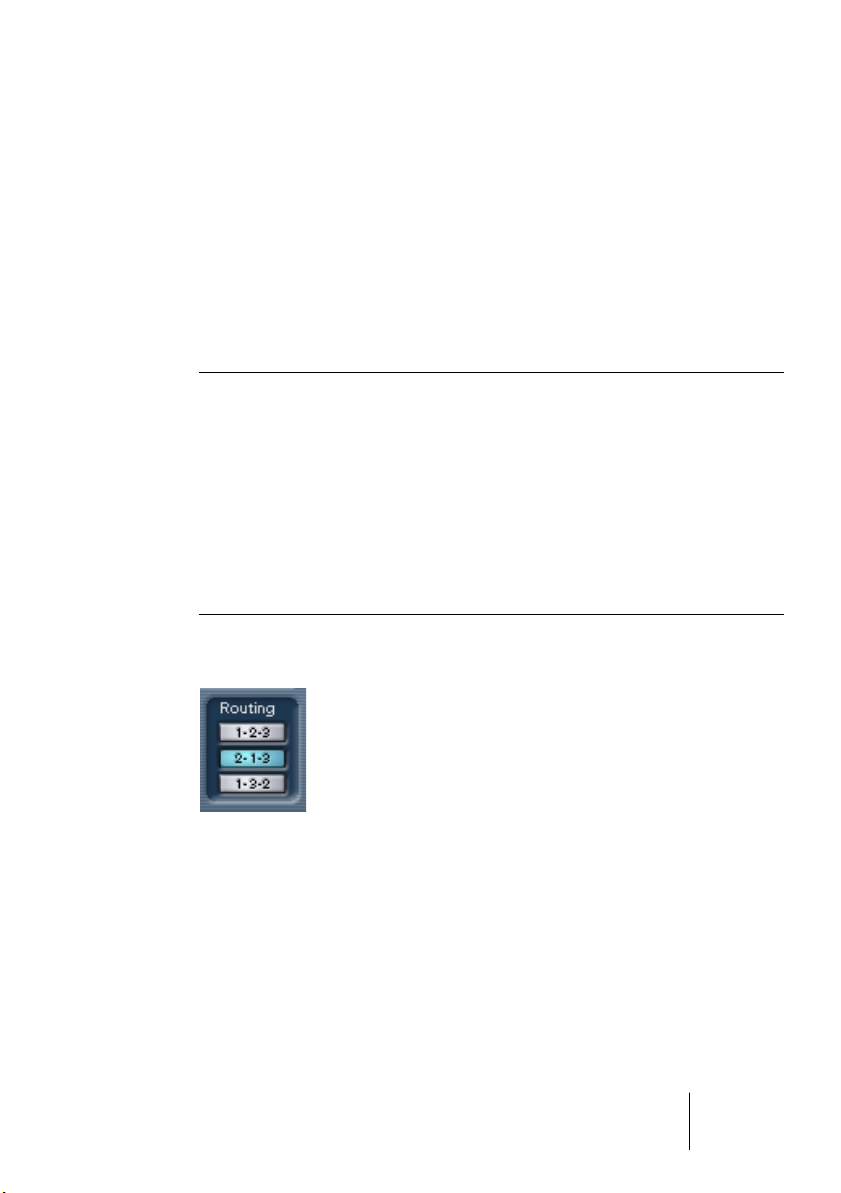
The Routing section
In the Routing section you can set the signal flow order for the three
processors. Changing the order of the processors can produce different results, and the available options allow you to quickly compare
what works best for a given situation. Beside each processor label is
a number. These numbers are used to represent the signal flow options shown in the Routing section. There are three routing options:
• 1-2-3 (Compressor-Gate-Limit)
• 2-1-3 (Gate-Compressor-Limit)
• 1-3-2 (Compressor-Limit-Gate)
CUBASE SX/SL
The included effect plug-ins 1 – 23
Page 24
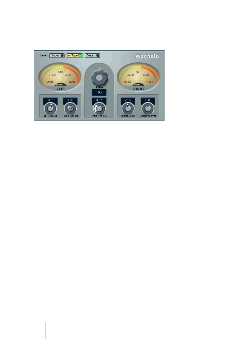
Magneto
Magneto brings the positive qualities of analog recording to your digital system, by providing the following capabilities:
• Simulates “tape saturation” and “tape overdrive” in a very realistic manner.
• Adds warmth, punch, and brilliance to a sound.
• Allows you to emphasize the “small details” in the sound.
• Works great on bass and guitar recordings as well as on drums, including individual samples and drum loops.
• Makes sampled drums and percussion sound much more “natural” and “warm”.
• Removes the “hardness” otherwise associated with digital audio recording.
All this makes Magneto suitable for processing both single sounds
and complete recordings. In other words; practically any recording
that you want to make sound warmer or more “natural”.
The algorithm behind Magneto is based on extensive studies and
measurements of analog tape recorders. Special care has been taken
to transfer the results of these studies into the digital domain.
•
If your audio material has been recorded digitally with Emphasis, it
contains a disproportionate amount of high frequencies. This will disturb the audio analysis in Magneto.
We recommend that you convert such material (removing Emphasis) before processing it with Magneto.
CUBASE SX/SL
1 – 24 The included effect plug-ins
Page 25

About the Drive parameter and Magneto output levels
• Magneto is different from analog tape recorders in one respect: On an analog
tape machine, you will get a lower output level when overdriving the tape “too
far”. This is known as the “saturation” effect. In Magneto, high Drive settings
do not have this effect on the Output level.
• Magneto needs headroom to perform its “magic”. For this reason you may note
a decrease in Output level (compared to the Input level) when using very low
Drive parameter settings (when the onTape meter shows levels below approximately +10dB). Since low Drive settings is not a normal situation (since the
plug-in then practically doesn’t have any audible effect), this is not something
you would normally encounter. However, if for some application a low Drive setting is required, you can compensate for the loss in level with the Output Level
parameter, see later in this text.
Metering Switch
Use the “Level” buttons to switch the meters between three modes:
•
Input
In this mode, the level of the input signal is shown. This should never exceed 0dB, as
mentioned above and described in more detail below.
•
onTape
In this mode, the meters show an equivalent of the level recorded on the simulated
“tape”. See the description of the Drive parameter for more details.
•
Output
This shows the output level for the entire plug-in. This should never exceed 0dB, see
below.
Clip LEDs
The Input and Output Clip LEDs, located on the corresponding “Level”
meter buttons, show if the signal is too “hot” (clipping occurs) at the
input or output. The advantage of these is that they indicate clipping
regardless of the mode the meters are switched to.
CUBASE SX/SL
The included effect plug-ins 1 – 25
Page 26

Input Level
This is used to make sure the input signal is strong enough, without
exceeding full level (so that clipping is avoided).
• If your input is already normalized, or sufficiently hot, leave this knob at 0.0 dB.
• If you need to adjust the input level, switch the Level metering to Input. Then
adjust the knob until the signal peaks are as close as possible to 0dB without
ever
exceeding that level!
Output Level
• Under normal conditions, the Output Level control should be left at 0.0dB.
The DSP algorithm in Magneto includes an “auto-gain” function which tries to
keep the output level as close as possible to 0dBfs, at high Drive settings.
• At very low drive settings (if onTape metering indicates peak levels at 7dB or
less – see the Drive parameter description for more info) you might need to amplify the signal using the Output Level control. However, always do this with the
Level metering Output button activated, so that you can check that clipping
doesn’t occur.
• At very high HF-Adjust settings, you might need to back off a bit on the Output level. Again, use Output metering to check.
If “digital clipping” occurs
If clipping occurs, (if the sound is heavily distorted), start by switching
to input metering and check the input levels. If the input levels seem
OK, switch to Output metering and adjust the Output Level as needed.
CUBASE SX/SL
1 – 26 The included effect plug-ins
Page 27

The main parameters
You can change the Magneto parameters in realtime – i.e. while the
audio material is played back – and the changes take effect more or
less immediately (depending on your system). This allows you to experiment to get a feeling for how the settings interact.
Input level, Output Level, “Level” buttons and Meters
These are used to adjust the level throughout the signal chain as described on the previous pages.
Drive
This is the main parameter. It is used to set the simulated analog tape
“recording level”. The value corresponds to how far above normal working level (0dB) you want to “record” on the “analog tape”. For example,
a setting of 7 means the “tape” is “overdriven” by 7dB.
The higher you set this, the more of the “tape saturation” effect you
will get.
Please use the following guidelines:
• Start out with a Drive setting of 10dB. Then adjust to taste.
• The effect of this parameter varies drastically with the frequency content and
other characteristics of the material. There is no “best setting” for all types of
recordings.
• If the material you are processing is already compressed or has been recorded on analog tape, a high Drive setting is not recommended, since it will
give the sound an unnatural character.
• When processing complete mixes, you will have to be more careful with the
Drive settings than when processing individual recordings. If all you want is to
add some “warmth” or “punch” to a complete mix, adjust the Drive setting
carefully.
• Always use the onTape meter to check out the effect of the setting on the material. This meter has to go pretty far above the 0dB level for Magneto to have
any audible effect on the sound. If the meter displays levels close to, or even
below 0dB, you get no “overdrive” or tape saturation effect at all! If this occurs, you need to raise the Drive setting or adjust the input level.
CUBASE SX/SL
The included effect plug-ins 1 – 27
Page 28

Characteristics
This affects the tonal characteristics of the “tape saturation” effect
controlled by the Drive parameter, as described above.
Tape Speed
This switches the tape simulation between 15 and 30 ips (inches per
second) tape speed. There are slight differences in the harmonic character of the two. How much you will actually be able to hear of this difference depends on the frequency content of the material.
HF-Adjust
Various types of tape, recording and playback equalizers and the general design of various tape machines has an overall impact on the character of the sound. This control is used to adjust the High frequency
content of the material to simulate those differences. It also has an effect on the perceived “warmth” of the sound.
This parameter can be used to compensate for the loss in high frequency that the overdrive effect introduces. Unlike on a real tape recorder it can also be used to boost the high frequency contents, compared to the original!
CUBASE SX/SL
1 – 28 The included effect plug-ins
Page 29
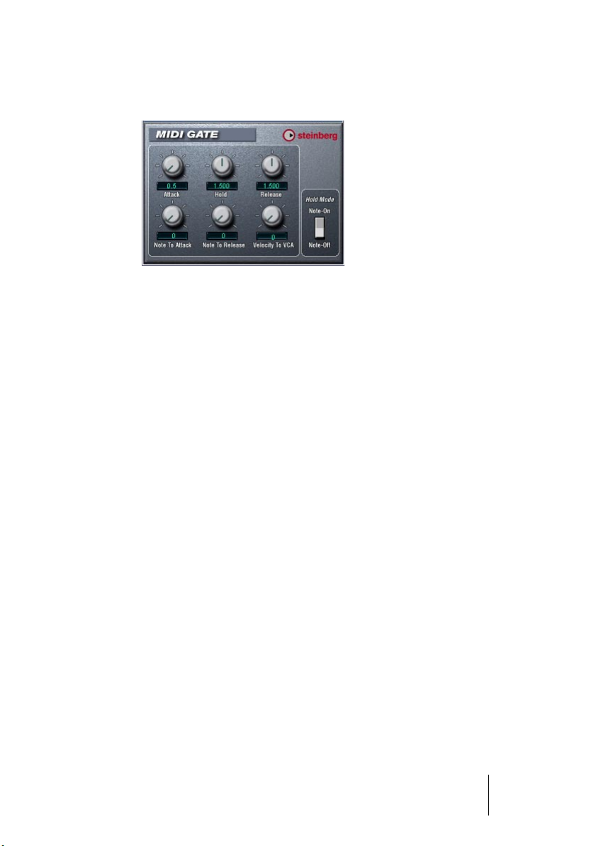
MIDI Gate
Gating, in its fundamental form, silences audio signals below a certain
set threshold level. I.e. when a signal rises above the set level, the
Gate opens to let the signal through while signals below the set level
are cut off. MIDI Gate however, is a Gate effect that is not triggered by
threshold levels, but instead by MIDI notes. Hence it needs both audio
and MIDI data to function.
Setting up
MIDI Gate requires both an audio signal and a MIDI input to function.
To set it up, proceed as follows:
1. Select the audio to be affected by the MIDI Gate.
This can be audio material from any audio track, or even a live audio input (provided
you have a low latency audio card).
2. Select the MIDI Gate as an insert effect for the audio track.
The MIDI Gate control panel opens.
3. Select a MIDI track to control the MIDI Gate.
This can be an empty MIDI track, or a MIDI track containing data, it doesn’t matter. However, if you wish to play the MIDI Gate in real-time – as opposed to having a recorded
part playing it – the track has to be selected for the effect to receive the MIDI output.
4. Open the Output (“out:”) pop-up menu for the MIDI track and select
the MIDI Gate option.
The MIDI Output from the track is now routed to the MIDI Gate.
CUBASE SX/SL
The included effect plug-ins 1 – 29
Page 30

What to do next depends on whether you are using live or recorded
audio and whether you are using real-time or recorded MIDI. We will
assume for the purposes of this manual that you are using recorded
audio, and play the MIDI in real-time.
Make sure the MIDI track is selected and start playback.
5. Now play a few notes on your MIDI keyboard.
As you can hear, the audio track material is affected by what you play on your MIDI keyboard.
The following MIDI Gate parameters are available:
Parameter Description
Attack This is used for determining how long it should take for the Gate to open
after receiving a signal that triggers it.
Hold Regulates how long the Gate remains open after a Note On or Note Off
message (see Hold Mode below).
Release This determines how long it takes for the Gate to close (in addition to the
value set with the Hold parameter).
Note To
Attack
Note To
Release
Velocity To
VCA
Hold Mode Use this switch to set the Hold Mode. In Note-On mode, the Gate will
The value you specify here determines to which extent the velocity values
of the MIDI notes should affect the Attack. The higher the value, the more
the Attack time will increase with high note velocities. Negative values
will give shorter Attack times with high velocities. If you do not wish to
use this parameter, set it to the 0 position.
The value you specify here determines to which extent the velocity values
of the MIDI notes should affect the Release. The higher the value, the
more the Release time will increase. If you do not wish to use this parameter, set it to the 0 position.
This controls to which extent the velocity values of the MIDI notes determine the output volume. A value of 127 means that the volume is controlled entirely by the velocity values, while a value of 0 means that
velocities will have no effect on the volume.
only remain open for the time set with the Hold and Release parameters,
regardless of the length of the MIDI note that triggered the Gate. In NoteOff mode on the other hand, the Gate will remain open for as long as the
MIDI note plays, and then apply the Hold and Release parameters.
CUBASE SX/SL
1 – 30 The included effect plug-ins
Page 31
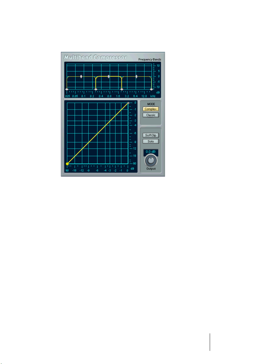
MultibandCompressor (Cubase SX only)
The MultibandCompressor allows a signal to be split in up to five frequency bands, each with its own freely adjustable compressor characteristic. The signal is processed on the basis of the settings that you
have made in the Frequency Band and Characteristics editors. You
can specify the level, bandwidth and compressor characteristics for
each band by using the various controls.
The Frequency Band editor
The Frequency Band editor is where you set the width of the frequency
bands as well as their level before compression. Two value scales and
a number of diamond-shaped handles are available. The vertical value
scale to the right gives you a clue to the approximate input gain level
of each frequency band.
The diamond-shaped handles provided in the Frequency Band editor
can be dragged with the mouse. You use them to set the corner frequencies and the input gain levels for up to five frequency bands. The
width of each frequency band can be adjusted by dragging horizontally.
CUBASE SX/SL
The included effect plug-ins 1 – 31
Page 32

The Level handles can be moved by dragging them up or down. If you
click and hold on a handle, its current value is displayed. Depending
on the handle type, corner frequency or level is shown.
• The diamond-shaped handles at the bottom are used to define the corner frequencies of the different frequency bands.
• By using the diamond-shaped handles on top of each frequency band you can
cut or boost the input gain by +/- 12dB before compression.
• To reset a Level handle to 0 dB, hold down the [Shift] key on your computer
keyboard and click on the handle.
• If you hold down the [Shift] key and click on the corner frequency handles,
they will be set to the same bandwidth (in octaves). The exact bandwidth they
will be set to is dependent on the number of bands currently used.
If you hold down [Ctrl] (Win) or [Command] (Mac) and move a handle,
the values will change in smaller steps.
Adding and removing frequency bands
To add a frequency band, drag the leftmost or rightmost corner frequency handle towards the middle of the window, and a new band will
automatically appear (given that you have less than the maximum number of five bands active). To remove a frequency band, drag the sec-
ond leftmost or second rightmost handle out of the left or right edge
of the window respectively.
About the Frequency scale
The horizontal value scale below the Frequency band display indicates
frequency. The maximum value on this scale corresponds to half the
sample rate of the audio file used. Hence, if a 44.1 kHz soundfile is
used, the highest frequency will be 22 kHz.
❐
In the digital domain, only frequencies of up to half the sample rate used
can be reproduced (Nyquist theorem). The values available in the Frequency band display do therefore depend on the sample rate of the audio material used.
CUBASE SX/SL
1 – 32 The included effect plug-ins
Page 33

The Solo button
The Solo button in the lower right part of the MultibandCompressor
panel can be used to separately monitor each of the frequency bands.
This function is useful both when editing bandwidth settings and compressor characteristics.
• To select another band while solo is active, click somewhere in the
(dark) area of the frequency band that you wish to monitor.
Using the Characteristics editor
By adding breakpoints and drawing curves you set the compressor
characteristic. Before you start using the Characteristics editor, you
have to select the frequency band you want to process. This is done
in the Frequency Band editor by clicking in the area inside the frequency band.
• A selected band is highlighted for editing both in the Frequency Band
and the Characteristics editors.
If you select another frequency band, the previously edited band characteristic is still
shown in the Characteristics window, but it is no longer highlighted or editable until
you select it again.
About breakpoints
• Clicking anywhere on the line will add a breakpoint.
• To remove a breakpoint, hold down [Shift] and click on it.
• The first breakpoint from which the line deviates from the straight diagonal will
be the threshold point.
• Creating a curve in the area below the diagonal input/output line will cause
compression. Compression decreases the output level in relation to the input
level.
• Creating a curve in the area above the diagonal input/output line will cause ex-
pansion. Expansion increases the output level in relation to the input level.
About the Compressor type (MODE)
• Classic mode works like a standard compressor with fixed attack and release
parameters.
• Complex mode features a new compression approach with a program adaptive circuit. The program adaptive compression automatically optimizes parameters according to the audio material.
CUBASE SX/SL
The included effect plug-ins 1 – 33
Page 34

The Output dial
The Output dial controls the total output level that the MultibandCompressor passes on to Cubase SX/SL. The range available is +/- 12 dB.
If the SoftClip function (see below) is active, the Output dial instead
controls the amount of soft clipping.
The SoftClip function
The SoftClip function is positioned at the very last stage of the internal
signal path, right after the Output dial. When active, it will ensure that
the total output to Cubase SX/SL never exceeds 0 dB. It works by
clipping the signal gently, generating harmonics which add a warm,
tube-like characteristic to the signal.
CUBASE SX/SL
1 – 34 The included effect plug-ins
Page 35

VST Dynamics
The VST Dynamics plug-in is similar to the Dynamics plug-in (see
page 18), but with the following differences:
• VST Dynamics has two additional modules: Auto Level and Soft Clip.
• The signal flow is fixed, in the order AutoGate-AutoLevel-CompressorSoftClip-Limiter.
Activating the individual processors
You activate the individual processors by clicking on their labels. Activated processors have highlighted labels. You can activate as many
processors as you want, but remember that not all processors are designed to work together. For example, “Limit” and “SoftClip” are both
designed to ensure that the output never exceeds 0dB, but achieves
this in different ways. To have both of them activated would be unnecessary.
• To turn off all activated VST Dynamics processors, click the lit On button to the right in the panel.
Clicking the button again activates the same configuration of processors.
Auto Gate section
This is exactly the same section as the AutoGate in the Dynamics
plug-in. See page 19 for details.
CUBASE SX/SL
The included effect plug-ins 1 – 35
Page 36

Auto Level section
Auto Level reduces signal level differences in audio material. It can be
used to process recordings where the level unintentionally varies. It will
boost low levels and attenuate high level audio signals. Only levels
above the set threshold will be processed, so low level noise or rumble
will not be boosted. If the input level is greater than 0dB, Auto Level will
react very fast, because it “looks ahead” in the audio material for strong
signal levels and can attenuate levels before they occur, thus reducing
the risk of signal clipping. Auto Level has the following parameters:
Parameter Description
Threshold Only levels stronger than the set threshold will be processed.
Reaction time buttons
(Slow, Mid, Fast)
Here you can set the amount of time it takes for Auto Level to
adjust the gain. Set this according to whether the program
level changes suddenly or over a length of time.
Compressor section
This is exactly the same section as the Compressor section in the
Dynamics plug-in. See page 22 for details.
Soft Clip section
Soft Clip is designed to ensure that the output level never exceeds 0dB,
like a limiter. Soft Clip, however, acts differently compared to a conventional limiter. When the signal level exceeds -6dB, SoftClip starts limiting
(or clipping) the signal “softly”, at the same time generating harmonics
which add a warm, tubelike characteristic to the audio material. Soft Clip
is simplicity itself to use as it has no control parameters. The meter indicates the input signal level, and thus the amount of “softclipping”. Levels
in the green area (weaker than -6dB) are unaffected, while levels in the
yellow-orange-red area indicate the degree of “softclipping”. The deep
red meter area to the right indicates input levels higher than 0dB.
• Avoid feeding Soft Clip with excessively high signal levels as audible
distortion may occur, although the output level will never exceed 0dB.
Limiter section
This is exactly the same section as the Limiter in the Dynamics plug-in.
See page 23 for details.
CUBASE SX/SL
1 – 36 The included effect plug-ins
Page 37

Filter plug-ins
This section contains descriptions of the plug-ins in the “Filter” category.
Q (Cubase SX only)
Q is a high-quality 4-band parametric stereo equalizer with two fully
parametric midrange bands. The low and high bands can act as either
standard shelving filters or fixed-gain high/low-cut filters.
Making settings
1. Click the corresponding On button below the EQ curve display to ac-
tivate any or all of the Low, Mid 1, Mid 2 or High equalizer bands.
When a band is activated, a corresponding eq point appears in the EQ curve display.
2. Set the parameters for an activated EQ band.
This can be done in several ways:
• By using the knobs.
• By clicking a value field and entering values numerically.
• By using the mouse to drag points in the EQ curve display window.
By using this method, you control both the Gain and Frequency parameters simultaneously. The knobs turn accordingly when you drag points. In addition, if the Mid 1 and
Mid 2 bands (M1 and M2) are activated there will be two points on each side of the
Gain/Frequency point that control the width (Q) parameter.
If you press [Shift] while dragging, values can be set in finer increments.
CUBASE SX/SL
The included effect plug-ins 1 – 37
Page 38

Parameters
Parameter Description
Low Freq (20-2000Hz) This sets the frequency of the Low band.
Low Gain (-20 to +20 dB) This sets the amount of cut/boost for the Low band.
Low Cut If this button is activated for the Low band, it will act as a
Low Cut filter. The Gain parameter will be fixed.
Mid 1 Freq (20-20000Hz) This sets the center frequency of the Mid 1 band.
Mid 1 Gain (+/- 20dB) This sets the amount of cut/boost for the Mid 1 band.
Mid 1 Width
(0.05-5.00 Octaves)
Mid 2 Freq (20-20000Hz) This sets the center frequency of the Mid 2 band.
Mid 2 Gain (-20 to +20 dB) This sets the amount of cut/boost for the Mid 2 band.
Mid 2 Width
(0.05-5.00 Octaves)
High Freq (200-20000Hz) This sets the frequency of the High band.
High Gain (-20 to +20 dB) This sets the amount of cut/boost for the High band.
High Cut If this button is activated for the High band, it will act as a
Output (-20 to +20 dB) This parameter allows you to adjust the overall output
Left/Stereo/Right/Mono
Modes
This sets the width of the Mid 1 band, in octaves. The
lower this value, the “narrower” the bandwidth.
This sets the width of the Mid 2 band, in octaves. The
lower this value, the “narrower” the bandwidth.
High Cut filter. The Gain parameter will be fixed.
level.
For stereo signals you can set independent curves for the
left and right channels by clicking the corresponding button. If the Stereo mode is activated, the curve will be applied to both channels.
When channel independent curves have been set, the
left/right channel curves will be colored green and red, respectively. The currently non-selected channel is shown
with a dotted curve. If you activate Stereo mode after independent curves have been set, the currently active
curve will be applied to both channels.
Mono mode is automatically activated for mono signals
and is otherwise unavailable.
CUBASE SX/SL
1 – 38 The included effect plug-ins
Page 39

StepFilter
StepFilter is a pattern-controlled multimode filter that can create rhythmic, pulsating filter effects.
General operation
StepFilter can produce two simultaneous 16-step patterns for the filter cutoff and resonance parameters, synchronized to the sequencer
tempo.
Setting step values
• Setting step values is done by clicking in the pattern grid windows.
• Individual step entries can be freely dragged up or down the vertical
axis, or directly set by clicking in an empty grid box. By click-dragging
left or right consecutive step entries will be set to the pointer position.
Setting filter cutoff values in the grid window.
CUBASE SX/SL
The included effect plug-ins 1 – 39
Page 40

• The horizontal axis shows the pattern steps 1-16 from left to right, and
the vertical axis determines the (relative) filter cutoff frequency and
resonance setting.
The higher up on the vertical axis a step value is entered, the higher the relative filter
cutoff frequency or filter resonance setting.
• By starting playback and editing the patterns for the cutoff and resonance parameters, you can hear how your filter patterns affect the
sound source connected to StepFilter directly.
Selecting new patterns
• Created patterns are saved with the project, and up to 8 different cutoff and resonance patterns can be saved internally.
Both the cutoff and resonance patterns are saved together in the 8 Pattern memories.
• To select new patterns you use the pattern selector.
New patterns are all set to the same step value by default.
Pattern Selector
Using pattern copy and paste to create variations
You can use the Copy and Paste buttons below the pattern selector
to copy a pattern to another pattern memory location, which is useful
for creating variations on a pattern.
• Click the Copy button with the pattern you wish to copy selected, select another pattern memory location, and click Paste.
The pattern is copied to the new location, and can now be edited to create variations
using the original pattern as a starting point.
CUBASE SX/SL
1 – 40 The included effect plug-ins
Page 41

StepFilter parameters
Parameter/Value Description
Base Cutoff This sets the base filter cutoff frequency. Cutoff values set in the
Cutoff grid window are values relative to the Base Cutoff value.
Base Resonance This sets the base filter resonance. Resonance values set in the
Resonance grid window are values relative to the Base Resonance value. Note that very high Base Resonance settings can
produce loud ringing effects at certain frequencies.
Glide This will apply glide between the pattern step values, causing val-
ues to change more smoothly.
Filter Mode This slider selects between lowpass (LP), bandpass (BP) or
highpass (HP) filter modes (from left to right respectively).
Sync 1/1-1/32
(Straight, Triplet
or Dotted)
Mix Adjusts the mix between dry and processed signal.
Output Sets the overall volume.
This sets the pattern beat resolution, i.e. what note values the
pattern will play in relation to the tempo.
CUBASE SX/SL
The included effect plug-ins 1 – 41
Page 42
Modulation plug-ins
This section contains descriptions of the plug-ins in the “Modulation”
category.
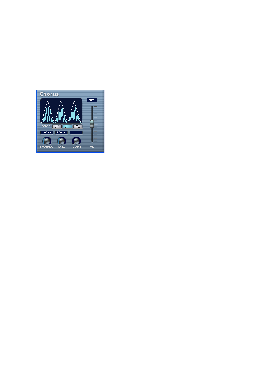
Chorus
The Chorus plug-in adds short delays to the signal, and pitch modulates the delayed signals to produce a “doubling” effect.
The parameters are as follows:
Parameter Description
Mix Sets the level balance between the dry signal and the effect. If Chorus
is used as a send effect, this should be set to maximum as you can
control the dry/effect balance with the send.
Shapes This sets the modulation waveform. Triangle produces smooth modu-
lation, saw produces ramp shaped modulation and pulse waveform
produces stepped modulation.
Frequency This sets the modulation rate.
Delay This controls the depth of the Chorus effect.
Stages This adds one to three more delay taps, producing a thicker, multi-lay-
ered chorus effect.
• Note that clicking and dragging in the display allows you to adjust the
Frequency and Delay parameters at the same time!
CUBASE SX/SL
1 – 42 The included effect plug-ins
Page 43

Flanger
Flanger is a classic flanger effect with stereo enhancement.
The parameters are as follows:
Parameter Description
Mix Sets the level balance between the dry signal and the effect. If the
Flanger is used as a send effect, this should be set to maximum as you
can control the dry/effect balance with the send.
Output Sets the overall volume.
Tempo sync
on/off
Rate If tempo sync is on, this is where you specify the base note value for
Tempo Sync
knob
Shape Sync
knob
Feedback This determines the character of the flanger effect. Higher settings pro-
Depth This sets the depth of the modulation sweep.
Delay This parameter affects the frequency range of the modulation sweep, by
Stereo Basis This sets the stereo width of the effect. 0% is mono, 50% original ste-
The button above the Rate knob is used to switch tempo sync on or off.
The button is yellow when tempo sync is on, and gray when it is off.
tempo syncing the flanger sweep (1/1 - 1/32, straight, triplet or dotted).
If tempo sync is off, the sweep rate can be set freely with the Rate knob,
without sync to tempo.
This is the note value multiplier (x1 to x10) for the flanger sweep when
tempo sync is used.
This changes the shape of the modulating waveform, altering the character of the flanger sweep.
duce a more “metallic” sounding sweep.
adjusting the initial delay time.
reo, and 100% maximum stereo enhancement.
CUBASE SX/SL
The included effect plug-ins 1 – 43
Page 44

You can also change parameters in the graphic display. This works as
follows:
• If tempo sync is on, you can set the base note value by clicking the
waveform and dragging left and right.
When tempo sync is off, this sets the Rate parameter.
• You can set the Depth parameter by clicking the waveform and dragging up and down.
This means you can freely adjust Rate and Depth at the same time by clicking and
dragging.
• By click-dragging the green/blue line in the display left or right you
can change the Stereo Basis parameter.
CUBASE SX/SL
1 – 44 The included effect plug-ins
Page 45

Metalizer
The Metalizer feeds the audio signal through a variable frequency filter,
with tempo sync or time modulation and feedback control.
Parameter Description
Mix Sets the level balance between the dry signal and the effect. If Metalizer
Output Sets the overall volume.
Tempo sync
on/off
Speed If tempo sync is on, this is where you specify the base note value for
On button Turns filter modulation on and off. When turned off, the Metalizer will
Mono button When this is on, the output of the Metalizer will be in mono.
Sharpness Governs the character of the filter effect. The higher the value, the nar-
Tone Governs the feedback frequency. The effect of this will be more notice-
Feedback The higher the value, the more “metallic” the sound.
is used as a send effect, this should be set to maximum as you can control the dry/effect balance with the send.
The button above the Speed knob is used to switch tempo sync on or
off. The button is yellow when tempo sync is on, and gray when it is off.
tempo-syncing the effect (1/1 - 1/32, straight, triplet or dotted). Note
that there is no note value modifier for this effect.
If tempo sync is off, the modulation speed can be set freely with the
Speed knob, without sync to tempo.
work as a static filter.
rower the affected frequency area, producing sharper sound and a
more pronounced effect.
able with high Feedback settings.
• Note that clicking and dragging in the display allows you to adjust the
Sharpness and Tone parameters at the same time!
CUBASE SX/SL
The included effect plug-ins 1 – 45
Page 46

Phaser
The Phaser plug-in produces the classic “swooshing” sound that
characterizes phasing. It works by shifting the phase of the signal and
adding it back to the original signal, causing partial cancellation of the
frequency spectrum.
Parameter Description
Mix Sets the level balance between the dry signal and the effect. If the
Phaser is used as a send effect, this should be set to maximum as you
can control the dry/effect balance with the send.
Output Sets the overall volume.
Tempo sync
on/off
Rate If tempo sync is on, this is where you specify the base note value for
Feedback This sets the amount of feedback. A higher value produces a more pro-
Tempo Sync
knob
Stereo Basis This sets the stereo width of the effect. 0% is mono, 50% original ste-
The button above the Rate knob is used to switch tempo sync on or off.
The button is yellow when tempo sync is on, and gray when it is off.
tempo syncing the Phaser sweep (1/1 - 1/32, straight, triplet or dotted). If tempo sync is off, the sweep rate can be set freely with the Rate
knob, without sync to tempo.
nounced effect.
This is the note value multiplier (x1 to x10) for the Phaser sweep when
tempo sync is used.
reo, and 100% maximum stereo enhancement.
CUBASE SX/SL
1 – 46 The included effect plug-ins
Page 47

You can also change parameters in the graphic display. This works as
follows:
• If tempo sync is on, you can set the base note value by clicking the
waveform and dragging left and right.
When tempo sync is off, this sets the Rate parameter.
• You can set the Feedback parameter by clicking the waveform and
dragging up and down.
This means you can freely adjust the Rate and Feedback at the same time by clicking
and dragging.
• By click-dragging the blue/green line in the display left or right you
can change the Stereo Basis parameter.
CUBASE SX/SL
The included effect plug-ins 1 – 47
Page 48

Ringmodulator
The Ringmodulator can produce complex, bell-like enharmonic sounds.
Ring modulators work by multiplying two audio signals. The ring modulated output contains added frequencies generated by the sum of, and
the difference between, the frequencies of the two signals.
The Ringmodulator has a built-in oscillator that is multiplied with the
input signal to produce the effect.
Parameter Description
Oscillator LFO
Amount
Oscillator Env.
Amount
Oscillator Wave Selects the oscillator waveform; square, sine, saw or triangle.
Oscillator Range Determines the frequency range of the oscillator in Hz.
Oscillator Frequency Sets the oscillator frequency +/- 2 octaves within the selected
Roll-Off Cuts high frequencies in the oscillator waveform, to soften the
LFO Waveform Selects the LFO waveform; square, sine, saw or triangle.
LFO Amount controls how much the oscillator frequency is affected by the LFO.
Env. Amount controls how much the oscillator frequency is affected by the envelope (which is triggered by the input signal).
Positive and negative values can be set, with center position representing no modulation. Left of center, a loud input signal will
decrease the oscillator pitch, whereas right of center the oscillator pitch will increase when fed a loud input.
range.
overall sound. This is best used when harmonically rich waveforms are selected (e.g. square or saw).
CUBASE SX/SL
1 – 48 The included effect plug-ins
Page 49

Parameter Description
LFO Speed Sets the LFO Speed.
LFO Env. Amount Controls how much the input signal level – via the envelope gen-
erator – affects the LFO speed. Positive and negative values can
be set, with center position representing no modulation. Left of
center, a loud input signal will slow down the LFO, whereas right
of center a loud input signal will speed it up.
Invert Stereo This inverts the LFO waveform for the right channel of the oscilla-
tor, which produces a wider stereo perspective for the modulation.
Envelope Generator
(Attack and
Decay dials)
Lock L<R When this button is enabled, the L and R input signals are
Mix Adjusts the mix between dry and processed signal.
Output Sets the overall volume.
The Envelope Generator section controls how the input signal is
converted to envelope data, which can then be used to control
oscillator pitch and LFO speed. It has two main controls:
Attack sets how fast the envelope output level rises in response
to a rising input signal.
Decay controls how fast the envelope output level falls in response to a falling input signal.
merged, and produce the same envelope output level for both
oscillator channels. When disabled, each channel has its own
envelope, which affects the two channels of the oscillator independently.
CUBASE SX/SL
The included effect plug-ins 1 – 49
Page 50

Rotary
The Rotary plug-in simulates the classic effect of a rotary speaker. A
rotary speaker cabinet features variable speed rotating speakers to
produce a swirling chorus effect, commonly used with organs. Rotary
features all the parameters associated with the real thing. The included
presets provide good starting points for further tweaking of the numerous parameters.
The parameters are as follows:
Parameter Description
Speed This controls the speed of the Rotary in three steps: Stop/Slow/Fast.
MIDI Ctrl Selects the MIDI continuous controller for the Speed parameter. See
page 51.
Mode Selects whether the Slow/Fast speed setting is a switch (left button
is lit), or a variable control (right button lit). When switch mode is selected and Pitch Bend is the controller, the speed will switch with an
up or down flick of the bender. Other controllers switch at 64.
Overdrive Applies a soft overdrive or distortion.
Crossover Freq. Sets the crossover frequency (200-3000Hz) between the low and
high frequency loudspeakers.
Mic Angle Sets the simulated microphone angle. 0 = mono, 180 = one mic on
each side.
Mic Distance Sets the simulated microphone distance from the speaker in inches.
Low Rotor Amp
Mod.
Adjusts amplitude modulation depth.
CUBASE SX/SL
1 – 50 The included effect plug-ins
Page 51

Parameter Description
Low Rotor Mix
Level
Hi Rotor Amp
Mod.
Hi Rotor Freq.
Mod.
Phasing Adjusts the amount of phasing in the sound of the high rotor.
Hi Slow Fine adjustment of the high rotor Slow speed.
Hi Rate Fine adjustment of the high rotor acceleration time.
Hi Fast Fine adjustment of the high rotor Fast speed.
Lo Slow Fine adjustment of the low rotor Slow speed.
Lo Rate Fine adjustment of the low rotor acceleration time.
Lo Fast Fine adjustment of the low rotor Fast speed.
Output Adjusts the overall output level.
Mix Adjusts the mix between dry and processed signal.
Adjusts overall bass level.
High rotor amplitude modulation.
High rotor frequency modulation.
Directing MIDI to the Rotary
For real-time MIDI control of the Speed parameter, MIDI must be
directed to the Rotary.
• Whenever the Rotary has been added as an insert effect (for an audio
track or an FX channel), it will be available on the output (“out:”) popup menu for MIDI tracks.
If Rotary is selected on the “out:” menu, MIDI will be directed to the plug-in from the
selected track.
CUBASE SX/SL
The included effect plug-ins 1 – 51
Page 52

Symphonic
The Symphonic plug-in combines a stereo enhancer, an auto-panner
synchronized to tempo and a chorus-type effect. For best results, apply the Symphonic effect to stereo signals.
The parameters are as follows:
Parameter Description
Mix Sets the level balance between the dry signal and the effect. If Sym-
phonic is used as a send effect, this should be set to maximum as you
can control the dry/effect balance with the send.
Tempo sync
on/off
Tempo Sync
pop-up
Tempo Sync
knob
Delay This determines the delay time and thus the character of the chorus
Depth This controls the depth of the chorus effect.
Rate This sets the modulation rate for the chorus effect, if activated.
The button below the Temp sync knob is used to switch tempo sync
on or off. The button is yellow when tempo sync is on, and gray when
it is off.
If tempo sync is on, this is where you specify the base note value for
tempo syncing the auto-panning (1/1 - 1/32, straight, triplet or dotted).
This is the note value multiplier (x1 to x10), determining the timing of
the auto-panning.
effect, if activated.
If you only want to use Symphonic as an auto-panner or a stereo enhancer, set this to 0%.
CUBASE SX/SL
1 – 52 The included effect plug-ins
Page 53

Parameter Description
Stereo Basis When the Auto-panner is activated, this sets the stereo width of the
panning.
When the Auto-panner is deactivated (Tempo sync off), this determines the depth of the stereo enhancer effect. 0% is mono, 50% original stereo, and 100% maximum stereo enhancement.
Output Adjusts the output level of the effect.
You can also change parameters in the graphic display. This works as
follows:
• You can set the Rate parameter by clicking the waveform and dragging left
and right.
• You can set the Depth parameter by clicking the waveform and dragging up
and down.
This means you can freely adjust Rate and Depth at the same time by clicking and
dragging.
• By click-dragging the green/blue line in the display left or right you can
change the Stereo Basis parameter.
CUBASE SX/SL
The included effect plug-ins 1 – 53
Page 54

Tranceformer
Tranceformer is a ring modulator effect, in which the incoming audio is
ring modulated by an internal, variable frequency oscillator, producing
new harmonics. A second oscillator can be used to modulate the frequency of the first oscillator, in sync with the Song tempo if needed.
Parameter Description
Mix Sets the level balance between the dry signal and the effect.
Output Adjusts the output level of the effect.
Tone Sets the frequency (pitch) of the modulating oscillator (1 to 5000 Hz).
Tempo sync
on/off
Speed If tempo sync is on, this is where you specify the base note value for
On button Turns modulation of the pitch parameter on or off.
Mono button Governs whether the output will be stereo or mono.
Depth Governs the depth of the pitch modulation.
Waveform
buttons
The button above the Speed knob is used to switch tempo sync on or
off. The button is yellow when tempo sync is on, and gray when it is off.
tempo-syncing the effect (1/1 - 1/32, straight, triplet or dotted). Note
that there is no note value modifier for this effect. If tempo sync is off,
the modulation speed can be set freely with the Speed knob, without
sync to tempo.
Sets the pitch modulation waveform.
• Note that clicking and dragging in the display allows you to adjust the
Tone and Depth parameters at the same time!
CUBASE SX/SL
1 – 54 The included effect plug-ins
Page 55

Other plug-ins
This section contains descriptions of the plug-ins in the “Other”
category.
Bitcrusher
If you’re into lo-fi sound, Bitcrusher is the effect for you. It offers the
possibility of decimating and truncating the input audio signal by bit
reduction, to get a noisy, distorted sound. You can for example make
a 24 bit audio signal sound like an 8 or 4 bit signal, or even render it
completely garbled and unrecognizable. The parameters are:
Parameter Description
Mode Select one of four operating modes for the Bitcrusher. Each mode will
produce a different sounding result. Modes I and III are nastier and noisier, while modes II and IV are more subtle.
Depth Use this to set the desired bit resolution. A setting of 24 gives the high-
est audio quality, while a setting of 1 will create mostly noise.
Sample
Divider
Mix This slider regulates the balance between the output from the Bitcrusher
Output Governs the output level from the Bitcrusher. Drag the slider upwards to
This sets the amount by which the audio samples are decimated. At the
highest setting (65), nearly all of the information describing the original
audio signal will be eliminated, turning the signal into unrecognizable
noise.
and the original audio signal. Drag the slider upwards for a more dominant effect, and drag it downwards if you want the original signal to be
more prominent.
increase the level.
CUBASE SX/SL
The included effect plug-ins 1 – 55
Page 56

Chopper
Chopper is a combined tremolo and autopan effect. It can use different
waveforms to modulate the level (tremolo) or left-right stereo position
(pan), either using tempo sync or manual modulation speed settings.
The parameters are as follows:
Parameter Description
Mix Sets the level balance between the dry signal and the effect. If Chopper
is used as a send effect, this should be set to maximum.
Tempo sync
on/off
Speed If tempo sync is on, this is where you specify the base note value for
Stereo/Mono
button
Waveform
buttons
Depth Sets the depth of the Chopper effect. This can also be set by clicking in
The button above the Speed knob is used to switch tempo sync on (yellow button) or off (gray button).
tempo-syncing the effect (1/1 - 1/32, straight, triplet or dotted). Note
that there is no note value modifier for this effect.
If tempo sync is off, the tremolo/auto-pan speed can be set freely with
the Speed knob, without sync to tempo.
Determines whether the Chopper will work as an auto-panner (button
set to “Stereo”) or a tremolo effect (button set to “Mono”).
Sets the modulation waveform.
the graphic display.
CUBASE SX/SL
1 – 56 The included effect plug-ins
Page 57
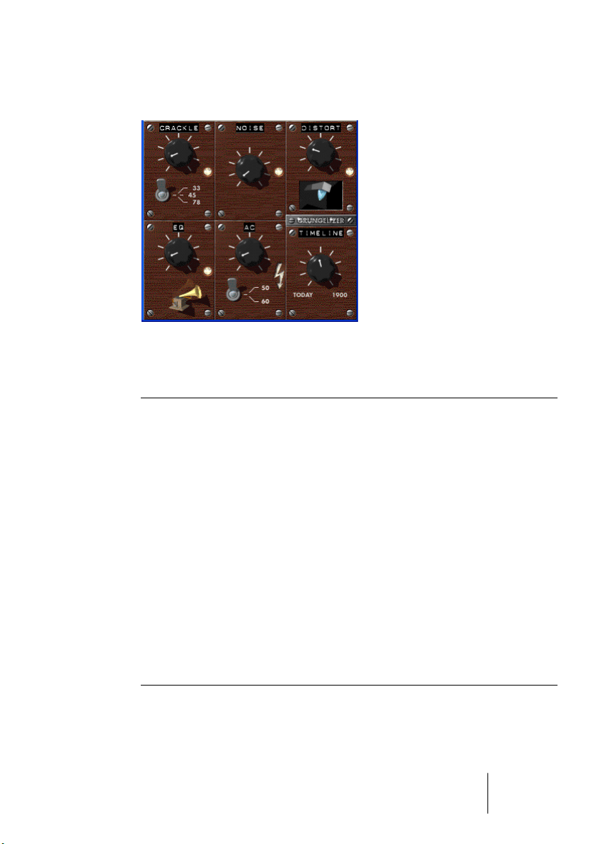
Grungelizer
The Grungelizer adds noise and static to your recordings – kind of like
listening to a radio with bad reception, or a worn and scratched vinyl
record. The available parameters are as follows:
Parameter Description
Crackle This adds crackle to create that old vinyl record sound. The farther to the
right you turn the dial, the more crackle is added.
RPM switch When emulating the sound of a vinyl record, this switch lets you set the
RPM (revolutions per minute) speed of the record (33/45/78 RPM).
Noise This dial regulates the amount of static noise added.
Distort Use this dial to add distortion.
EQ Turn this dial to the right to cut off the low frequencies, and create a
more hollow, lo-fi sound.
AC This emulates a constant, low hum of AC current.
Frequency
switch
Timeline This dial regulates the amount of overall effect. The farther to the right
This sets the frequency of the AC current (50 or 60Hz), and thus the
pitch of the AC hum.
(1900) you turn this dial, the more noticeable the effect.
CUBASE SX/SL
The included effect plug-ins 1 – 57
Page 58

Apogee UV 22 HR (Cubase SX only)
The UV22 HR is a dithering plug-in, based on an advanced algorithm
developed by Apogee (for an introduction to the concept of dithering,
please refer to the chapter “Audio Effects” in the Operation Manual).
You can use the UV22 HR plug-in for all dithering situations, except
when working with surround audio. This is because the UV22 HR is a
standard “stereo in” – “stereo out” plug-in (as opposed to the SurroundDither plug-in, see page 70).
The following options can be set in the UV 22 HR control panel:
Option Description
Normal Try this first, it is the most “all-round” setting.
Low This applies a lower level of dither noise.
Autoblack When this is activated, the dither noise is gated (muted) during silent
passages in the material.
Bit Resolution The UV22 HR supports dithering to multiple resolutions: 8, 16, 20 or
24 bits. You select the desired resolution by clicking the corresponding button.
❐
Dither should always be applied post output bus fader.
CUBASE SX/SL
1 – 58 The included effect plug-ins
Page 59

Apogee UV22
The UV22 is a stereo in-stereo out dithering plug-in, based on an advanced algorithm developed by Apogee (for an introduction to the
concept of dithering, please refer to the chapter “Audio Effects” in the
Operation Manual). The UV22 plug-in always dithers to 16 bit resolution, which means you should only use it when exporting to 16 bit audio format.
The following options can be set in the control panel:
Option Description
Normal Try this first, it is the most “all-round” setting.
Low This applies a lower level of dither noise.
Autoblack When this is activated, the dither noise is gated (muted) during silent
passages in the material.
❐
Dither should always be applied post output bus fader.
The included effect plug-ins 1 – 59
CUBASE SX/SL
Page 60
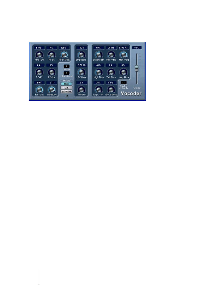
Vocoder
The Vocoder can apply sound/voice characteristics taken from one
signal source, called the “modulator” and apply this to another source,
called the “carrier”. A typical application of a vocoder is to use a voice
as a modulator and an instrument as a carrier, making the instrument
“talk”. A vocoder works by dividing the source signal (modulator) into
a number of frequency bands. The audio attributes of these frequency
bands can then be used to modulate the carrier.
The Vocoder has a built-in carrier (basically a simple polyphonic synthesizer) but you can also use an external carrier, see page 61.
Setting up – using MIDI
In this mode, the Vocoder is set up slightly differently than other plugin effects. This is because this setup requires both an audio signal (as
the modulator source) and a MIDI input (to play the carrier) to function. To set up for using an external carrier, see page 61.
To set up for use, proceed as follows:
1. Select a source for the modulator.
The modulator source can be audio material from any audio track, or even a live audio
input routed to an audio track (provided you have a low latency audio card).
• Good modulator source material are talking or singing voices or percussive sounds, e.g. drum loops.
Static pads or soft ambient material are generally less appropriate for use as modulators, but there are no absolute rules as to what could be used as a modulator source.
CUBASE SX/SL
1 – 60 The included effect plug-ins
Page 61

2. Select the Vocoder as an insert effect for the audio channel with the
modulator signal.
3. Make sure that the Vocoder Mode is set to “MIDI”.
4. Select a MIDI track.
This can be an empty MIDI track, or a MIDI track containing data, it doesn’t matter.
However, if you wish to play the Vocoder in real-time – as opposed to having a recorded part playing it – the track has to have monitoring activated (or be record enabled) for the Vocoder to receive the MIDI output.
5. Select “Vocoder” from the MIDI “out:” pop-up menu for the MIDI track.
The MIDI Output from the track is now routed to the Vocoder. There is an indicator on
the Vocoder panel below the Mode switches that blinks when receiving MIDI.
That concludes setting up – you are now ready to start vocoding!
What you do next depends on whether you are using live or recorded
audio as the modulator source and whether you are using real-time or
recorded MIDI as the carrier input. We will assume for the purposes
of this manual that you are using recorded audio as the modulator,
and play the carrier in real-time.
6. Make sure the MIDI track is record enabled and start playback.
7. Now play a few notes on your MIDI keyboard.
As you can hear, the audio track material, or rather its formant characteristics, is now
applied to the Vocoder’s built-in sound source!
Setting up – using an external carrier
There are two modes for using an external carrier:
• “Ext” mode is when the carrier and the modulator can be any two audio sources.
The synth section is disabled and grayed out when this mode is selected. MIDI input
and the Gap Thru Vocoder parameter are also disabled.
• “MIDI+Ext” mode mixes the audio carrier with the Vocoder’s synth sound.
This is described on page 62.
CUBASE SX/SL
The included effect plug-ins 1 – 61
Page 62

To use an external carrier instead of the built-in synth (“Ext mode”),
you set up as follows:
1. Create a Group channel from the Add Track submenu on the Project
menu.
2. Open an audio file you wish to use as the carrier source and place it
on an empty audio track.
3. Pan the audio channel full right in the Mixer or in the Inspector.
4. Route the output of the audio channel to the group.
5. Open an audio file you wish to use as the modulator source and place
it on another empty audio track.
Events on the two audio tracks (carrier and modulator) have to play back simultaneously for the Vocoder to work.
6. Pan the modulator audio channel full left in the Mixer or in the Inspector.
7. Route the output of the modulator audio channel to the group.
8. Select the Vocoder as an insert effect for the group channel.
9. Open the Vocoder panel and activate the “Ext.” Mode button.
10.If you now start playback, the carrier channel will be modulated by the
modulator channel!
Note that the synth section on the left half of the Vocoder panel and the “Gap Thru”
parameter are now disabled.
Setting up – using an external carrier plus MIDI
Setting up is the same as for using an external carrier, except that a
MIDI track with its output routed to the Vocoder should also be present.
The MIDI track can either play the Vocoder synth in real time or from
prerecorded parts. Make sure that monitoring (or record enable) is activated for the track so that the Vocoder synth will receive MIDI played in
real time.
• Set up as described, and activate “MIDI+Ext.” mode on the Vocoder
panel.
Any incoming MIDI now triggers the Vocoder synth, and the synths output is mixed
with the audio carrier signal.
CUBASE SX/SL
1 – 62 The included effect plug-ins
Page 63

Vocoder parameters
The Vocoder parameters govern the general sound quality of the
vocoded sound.
Parameter Description
Number of
Bands
Bandwidth This sets the bandwidth for the frequency bands, which affects the
Min./Max. Freq. These parameters set the minimum and maximum frequency limits for
log/lin Log/Lin controls how the frequency bands are spaced between the
Env.Speed This determines the attack and release times of the Vocoder enve-
High Thru This lets through high frequencies around the “S” frequency from the
Talk Thru Adjusts the level of the original input signal passed to the Vocoder
Gap Thru Gap Thru (only available in MIDI mode) sets the level of the original in-
Output This controls the output level of the Vocoder.
Emphasis This is a highpass filter, gradually cutting lower frequencies while let-
This governs how many frequency bands the modulator signal is divided into (2-24). Fewer bands will provide a thinner more resonant
sound, whereas using more bands will make the sound fuller and
more intelligible.
overall timbre. Very narrow bandwidth settings will produce a thin,
whistle-like sound.
the Vocoder, respectively.
minimum and maximum frequencies. Log = equal spacing in octaves,
Lin = equal spacing in Hz. This affects the basic timbre of the Vocoder.
lope. Fast settings will cause the modulator signal to trigger the Vocoder instantly, longer settings will gradually increase the attack/
release times, providing a more subtle Vocoder effect. If set to
“HOLD” the modulator is “frozen”, and doesn’t affect the carrier synth
at all.
original input signal while notes are played.
output while notes are played.
put signal that is passed to the Vocoder output when no MIDI notes
are being played. This lets you apply the Vocoder to a vocal track
adding vocoded parts just where you want them.
ting high frequencies pass.
CUBASE SX/SL
The included effect plug-ins 1 – 63
Page 64

Vocoder synth parameters
If the built-in synthesizer is the carrier, it is the sound of this instrument
that the modulator source is applied to. The synth is polyphonic with
up to 8 voices and features 2 oscillators per voice. The synth has the
following parameters:
Parameter Description
Voices This sets the number of voices for the synth (1-8).
Fine Tune Tunes the oscillators ± a semitone, in cents (100th of a semitone)
steps.
Pitch Bend Sets the up/down range of the Pitch Bend in semitone steps (1-12).
Noise Adds white noise to the sound.
NoiseMod This makes the oscillators modulate the noise level. This gives the
noise a rasping sound, turning “sss” into “zzz”.
P.Drift Adds random pitch variation to the oscillators.
P.Glide This makes the pitch glide between notes played. The parameter con-
trols the time it takes for the pitch to glide from one note to the next.
P.Bright This is a lowpass filter that can be used to soften the tone of the oscil-
lators. It does not affect the white noise generator.
P.Detune Allows you to detune one of the oscillators in cent steps.
LFO Rate Controls the LFO rate (for vibrato).
Vibrato Adds vibrato to the oscillators. This can also be controlled by using
the Mod Wheel.
CUBASE SX/SL
1 – 64 The included effect plug-ins
Page 65

SMPTE Generator (Cubase SX only)
This plug-in is not an effect device. It sends out SMPTE time code to
an audio output, allowing you to synchronize other equipment to Cubase SX (provided that the equipment can sync directly to SMPTE
time code). This can be very useful if you don’t have access to a MIDIto-time code converter.
The following items and parameters are available:
• Generate Button
Activate this to make the device generate SMPTE time code.
• Link Button
This synchronizes the time code output to the Transport time positions.
When Link is activated, the time code output will exactly match the play position in
Cubase SX.
Activating the Generate button makes the device send the SMPTE time code in “free
run” mode, meaning that it will output continuous time code, independently from the
transport status in Cubase SX. If you wish to “stripe” a tape with SMPTE, you should
use this mode.
• Start Time
This sets the time at which the SMPTE Generator starts, when activated in “free run”
mode (Link button off). To change the Start time, click on a digit and move the mouse
up or down.
• Current Time
When Link is on this shows the current position in Cubase SX. If Link is off it shows the
current time of the SMPTE Generator in “free run” mode. This cannot be set manually.
CUBASE SX/SL
The included effect plug-ins 1 – 65
Page 66

• Framerate
This defaults to the frame rate set in the Project Setup dialog. If you wish to generate
time code in another frame rate than the Project is currently set to (for example to
stripe a tape), you can select another format on the Framerate pop-up (provided that
“Link” is off).
Note, however, that for the other device to synchronize correctly with Cubase SX, the
framerate has to be the same in the Project Setup dialog, the SMPTE Generator and in
the receiving device.
Example - Synchronizing a device to Cubase SX
Proceed as follows:
1. Connect the SMPTE Generator as an insert effect on an audio channel, and route the output of that channel to a separate output.
Make sure that no other insert or send effects are used on the time code channel. You
should also disable EQ, if this is active.
2. Connect the corresponding output on the audio hardware to the time
code input on the device you wish to synchronize to Cubase SX.
Make all necessary settings in the other device, so that it is set to synchronize to incoming timecode.
3. Adjust the level of the time code if needed, either in Cubase SX or in
the receiving device.
Activate Generate button (make the device send the SMPTE time code in “free run”
mode) to test the level.
4. Make sure that the frame rate in the receiving device matches the
frame rate set in the SMPTE Generator.
5. Activate the Link button.
The SMPTE Generator will now output time code that matches the position of the
Cubase SX Transport panel.
• Press Play on the Cubase SX Transport panel.
The other device is now synchronized and will follow any position changes set with the
Cubase SX transport controls.
CUBASE SX/SL
1 – 66 The included effect plug-ins
Page 67

Reverb plug-ins
This section contains descriptions of the plug-ins in the “Reverb” category.
Reverb A
Reverb A is a reverb plug-in which provides smooth, dense reverb
effects. Reverb A has the following parameters:
Parameter Description
Mix Sets the level balance between the dry signal and the effect (wet). If
Reverb A is used as a send effect, this should be set to maximum wet,
as you can control the dry/wet balance with the send.
Room Size This setting determines the “size” of the simulated room environment.
Predelay This parameter sets a delay between the direct sound and the reverb
effect output. A short predelay before the reverb reduces reverb “clutter” which blurs the sound, and makes the reverb effect more naturalsounding.
Reverb Time This parameter sets the length of the reverb time.
Filter HighCut This filters out high frequencies for the reverb, which can make the re-
verb sound softer.
Filter LowCut This filters out the lower frequencies for the reverb. It can be used to
reduce low frequency “rumble”.
CUBASE SX/SL
The included effect plug-ins 1 – 67
Page 68
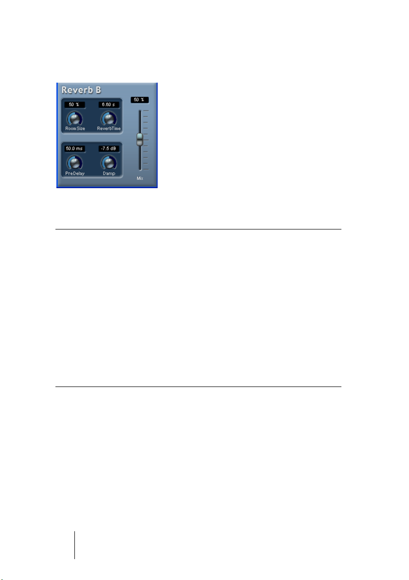
Reverb B
The Reverb B provides reverb with low processor demands. It has the
following parameters:
Parameter Description
Mix Sets the level balance between the dry signal and the effect. If Reverb
B is used as a send effect, this should be set to maximum as you can
control the dry/effect balance with the send.
Room Size Governs the “size” of the simulated room environment.
Predelay This parameter sets a delay between the direct sound and the reverb
effect output. A short predelay before the reverb reduces reverb “clutter” which blurs the sound, and makes the reverb effect more naturalsounding.
Reverb Time This parameter sets the length of the reverb effect.
Damp This parameter “dampens” the higher frequencies, producing a rounder
and smoother sounding reverb.
CUBASE SX/SL
1 – 68 The included effect plug-ins
Page 69

Surround plug-ins (Cubase SX only)
This section describes the plug-ins in the “Surround” category.
Mix6To2 (Cubase SX only)
The Mix6To2 effect allows you to control the levels of up to six surround channels, and to mix these down to a stereo output. The pop-up
menu contains a number of speaker arrangement presets that correspond to some default surround formats. The Mix6To2 lets you quickly
mix down your surround mix format to stereo, and to include parts of
the surround channels in the resulting mix.
• Note that Mix6To2 does not simulate a surround mix or add any psy-
cho-acoustical artifacts to the resulting output – it is simply a mixer.
Also note that the Mix6To 2 should be placed in one of the post fader
insert effect slots for the output bus.
Each of the surround channels has the following parameters:
• Two volume faders that govern the levels of the surround bus to the left and
right side of the (master) bus.
• A Link button that links the two volume faders.
• Two Invert buttons allow you to invert the phase of the left and right side of the
surround bus.
The Master bus has the following parameters:
• A Link button that links the two Master faders.
• A Normalize button. If activated, the mixed output will be normalized, i.e. the
output level will automatically be adjusted so that the loudest signal is as loud
as possible without clipping.
CUBASE SX/SL
The included effect plug-ins 1 – 69
Page 70

SurroundDither (Cubase SX only)
SurroundDither is not an “effect” as such. Dithering is a method for
controlling the noise produced by quantization errors in digital recordings. The theory behind this is that during low level passages, only a
few bits are used to represent the signal, which leads to quantization
errors and hence distortion. For example, when “truncating bits”, as a
result of moving from 24- to 16-bit resolution, quantization errors are
added to an otherwise immaculate recording. By adding a special
kind of noise at an extremely low level, the effect of these errors is minimized. The added noise could be perceived as a very low-level hiss
under exacting listening conditions. However, this is hardly noticeable
and much preferred to the distortion that otherwise occurs.
When should I use SurroundDither?
• Basically anytime you mix down to a lower resolution, either in real-
time (playback) or with the Export Audio Mixdown function, you should
consider dithering.
• Since SurroundDither is capable of dithering up to six channels at the
same time, it is recommended if you’re using surround channels.
If not, you may want to use the UV22 HR instead, see page 58.
The following options can be set in the SurroundDither control panel:
Dithering Type
There are no hard and fast rules for the following options, it all depends on the type of material you are processing. We recommend
that you experiment and let your ears be the final judge:
Option Description
Off No dithering is applied.
Type 1 Try this first, it is the most “all-round” type.
Type 2 This method emphasizes higher frequencies more than Type 1.
CUBASE SX/SL
1 – 70 The included effect plug-ins
Page 71

Noise Shaping Options (Off, Type 1 - 3)
This parameter alters the character of the noise added when dithering. Again, there are no fixed general rules, but you may notice that the
higher the number selected here, the more the noise is moved out of
the ear’s most sensitive range, the mid-range.
Ditherbits
This is used to specify the intended bit resolution for the final result.
• The section has six buttons, one for each channel.
• Above each button there are six corresponding value fields that dis-
play the bit resolution the files will be converted to.
Clicking a button several times cycles through the available bit resolution values.
An Example
Say you have set up a project to record 24-bit files. After completion,
you want to create a digital 16-bit master for CD burning. Proceed as
follows:
1. Add SurroundDither to a post fader insert effect slot for the output bus.
I.e. in one of the last two slots.
2. Open the control panel for SurroundDither, and select the Dithering
and Noise Shaping Type.
3. Set the Ditherbit destination to “16” for all the master mix outputs currently used, as defined in the VST Connections dialog.
If you are not using Surround channels, this will be Channel 1 and 2.
4. When you now play back the Project, the digital outputs of your audio
hardware will output the mix with 16-bit resolution, with dithering applied.
CUBASE SX/SL
The included effect plug-ins 1 – 71
Page 72

SurroundPan (Cubase SX only)
The SurroundPan plug-in provides a graphical overview representing
the speaker arrangement and the sound source, allowing you to dynamically position the audio in the surround field.
This plug-in is described in detail in the Operation Manual chapter
“Surround Sound”.
CUBASE SX/SL
1 – 72 The included effect plug-ins
Page 73

2
The included VST Instruments
Page 74

A1 Synthesizer
The A1 is a dual oscillator software synthesizer with the following
main features:
• The A1 is polyphonic with up to 16 voices.
• Multimode filter.
Lowpass, bandpass, highpass and notch filter types are available.
• PWM (Pulse Width Modulation).
• FM (Frequency Modulation).
• Ring Modulator.
• Built-in stereo chorus/flanger effect.
• The A1 receives MIDI in Omni mode (on all MIDI channels).
You don’t need to select a MIDI channel to direct MIDI to the A1.
• The A1 responds to MIDI Controller messages.
See page 84.
CUBASE SX/SL
2 – 74 The included VST Instruments
Page 75

A1 Parameters
Oscillator 1 and 2 section
This section contains parameters affecting the oscillators.
Parameter Description
Octave Clicking on the outer ring of the dial allows you to tune the oscillator in
octave steps.
Semitone Clicking on the inner ring of the dial allows you to tune the oscillator in
semitone steps.
Detune Tunes the oscillator in cent (100th of a semitone) steps.
Shape This sets the waveform for the oscillator (sine, triangle, sawtooth or
pulse).
PW Sets the width of the waveform when a Pulse waveform is selected.
Turning the dial clockwise gradually produces a narrower pulse waveform. Note that a PW setting of 100% will lead to complete cancellation of the waveform (i.e. silence), if no modulation (see PW Mod) is
applied.
PW Mod This parameter determines the amount of Pulse Width Modulation
(PWM) by the LFO. Positive and negative values can be set. A Pulse
waveform must be selected for PW Mod to function.
Pitch Mod This parameter determines the amount of oscillator 1 pitch modulation
(or vibrato) by the LFO. Positive and negative values can be set.
FM (Oscillator
1 only)
Governs the amount of frequency modulation. See page 84.
FM Env (Osc 1
only)
This governs how much the Filter Envelope parameters affects the FM
amount. Positive and negative values can be set. See page 84.
CUBASE SX/SL
The included VST Instruments 2 – 75
Page 76

LFO section
This section contains the LFO (Low Frequency Oscillator) parameters.
LFOs are used to modulate parameters like pitch (vibrato) or the filter
cutoff.
Parameter Description
LFO Wave This sets the LFO waveform for modulating parameters:
Sine and triangle waves have a smooth waveform, suitable for normal vibrato.
Saw produces a ramp up or down cycle.
S&H produces stepped random modulation.
Square waves produce cycles that abruptly change between two
values.
Random produces smooth random modulation.
LFO Sync If this is activated, the LFO rate will be synchronized to the se-
quencer tempo in various bar/beat divisions that can be set with
the LFO Speed parameter.
LFO Speed Governs the modulation rate of the LFO.
LFO Speed
(tempo sync on)
If the “LFO Sync” parameter is activated, the LFO rate will be synchronized to the sequencer tempo, according to the different beat
divisions that can be specified here.
CUBASE SX/SL
2 – 76 The included VST Instruments
Page 77

Filter section
This section contains the filter parameters:
Parameter Description
Filter type Sets the filter type to either lowpass, highpass, bandpass or notch. The
filter types are described on page 83.
Cutoff Controls the filter frequency or “cutoff”. If a lowpass filter is used, it
could be said to control the opening and closing of the filter, producing the classic “sweeping” synthesizer sound. How this parameter operates is governed by the filter mode (see page 83).
Resonance The Resonance control for the filter. Raise this for a more pronounced
filter sweep effect.
Drive This parameter can overdrive the filter to produce distortion effects.
Filter Envelope Controls how much the filter cutoff should be affected by the Filter
Envelope. Negative values will invert the filter envelope settings.
Filter Velocity Determines how the filter cutoff will be affected by velocity, i.e. how
hard or soft you strike a key. Positive values will increase the cutoff frequency the harder you strike a key. Negative values will invert this relationship.
Filter Envelope
Attack/Decay/
Sustain/
Release
Cutoff Mod This controls how much the filter cutoff is modulated by the LFO (low
Keytrack If this parameter is set to values over 0, the filter cutoff frequency will
The Filter Envelope Attack, Decay, Sustain and Release parameters.
Use these parameters to determine how the filter cutoff should open
and close with time, when a note is played. Values can be changed
using the dials or by dragging the breakpoints in the graphic display.
frequency oscillator).
increase the further up on the keyboard you play. Negative values invert this relationship.
CUBASE SX/SL
The included VST Instruments 2 – 77
Page 78
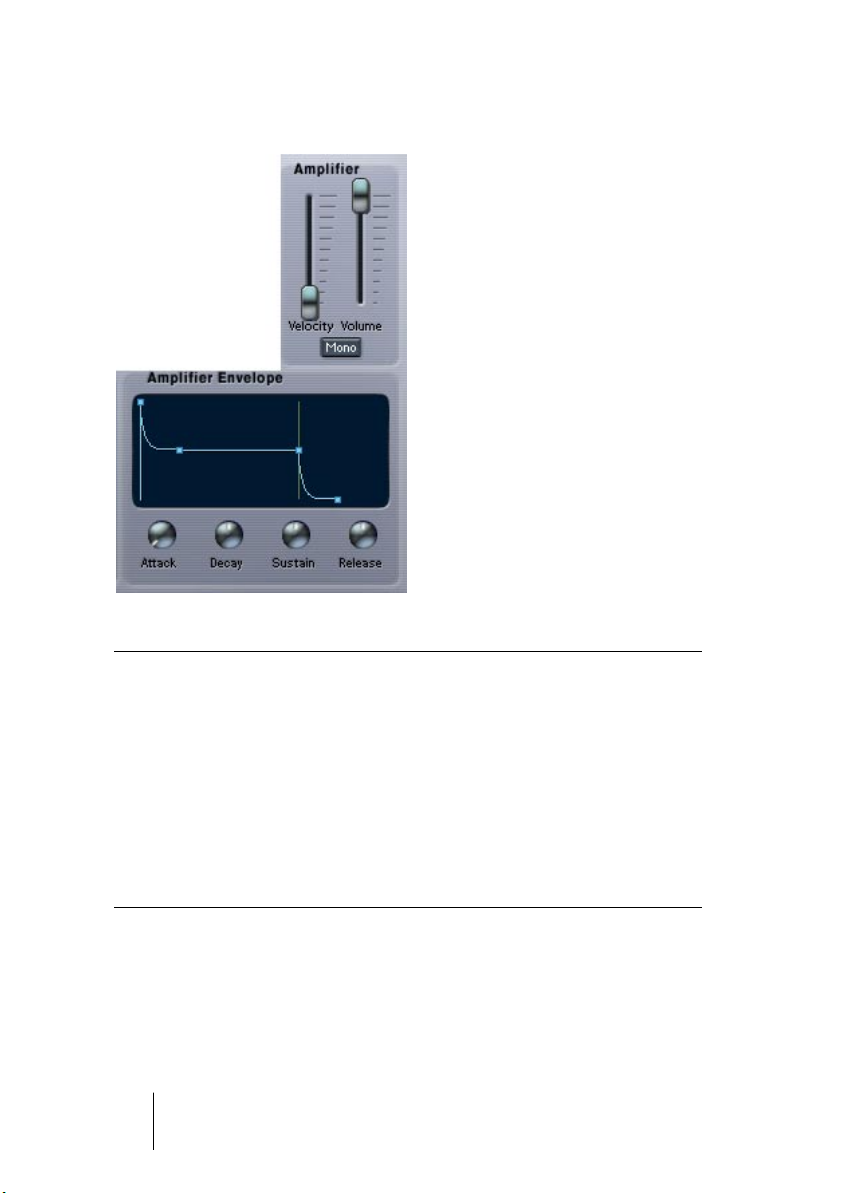
Amplifier section
This section contains the Amplifier parameters:
Parameter Description
Amplifier Attack/
Decay/Sustain/
Release
Velocity This determines how much the Amplifier Envelope should be af-
Mono When this is activated, the A1 will be monophonic, i.e. only play
The Amplifier Attack, Decay, Sustain and Release parameters. Use
these parameters to determine how the volume should change
with time, when a note is played. Values can be changed using the
dials or by dragging the breakpoints in the graphic display.
fected by velocity, i.e. by how hard or soft you strike a note on the
keyboard.
one voice at a time.
CUBASE SX/SL
2 – 78 The included VST Instruments
Page 79

The Chorus/Flanger section
Adding chorus will introduce a wide stereo effect and generally “fatten”
sounds. With higher Feedback settings, more metallic sounding flanging
effects are produced. The section contains the following parameters.
Parameter Description
Speed Controls the modulation rate of the effect.
Feedback Increasing the Feedback parameter value results in a more pro-
nounced sweeping metallic sound. Positive and negative feedback
values can be set.
Depth Controls the depth of the modulation.
Quad Adds more delay taps, producing richer chorus/flanger effects.
On This turns the chorus/flanger effect on or off.
The Glide section
This section contains the glide parameters.
Parameter Description
On If set to “On” the pitch will glide up or down between notes played.
Speed Controls the time it takes for the pitch to glide from one note to the
next when using Glide.
CUBASE SX/SL
The included VST Instruments 2 – 79
Page 80

The Mixer section
This section controls the relative levels of Oscillator 1 and 2. Here you
also set the levels of the Ring Modulator and Noise Generator outputs.
Parameter Description
Osc 1 Sets the volume of oscillator 1.
Ring Mod Controls the level of the ring modulator. See page 83.
Osc 2 Sets the volume of oscillator 2.
Noise Noise is commonly used to create wind and percussion type
sounds. To hear the noise generator output on its own, turn down
the osc 1 and 2 output in the Mixer.
CUBASE SX/SL
2 – 80 The included VST Instruments
Page 81

Mod Wheel section
This section controls how the modulation wheel affects certain parameters. Positive and negative values can be set. For example, this can be
used to set up so that moving the mod wheel gradually removes Filter
Cutoff LFO modulation and instead introduces vibrato.
Parameter Description
Pitch Mod Governs the amount of LFO modulation of the oscillator frequency
(vibrato) using the mod wheel.
Cutoff Mod Governs the amount of LFO modulation of the Filter Cutoff para-
meter using the mod wheel.
Cutoff Governs how much the mod wheel affects the Filter Cutoff fre-
quency. Positive values raise the cutoff frequency when moving the
mod wheel forward. Negative values invert this relationship.
CUBASE SX/SL
The included VST Instruments 2 – 81
Page 82

The Parameter display
The Parameter display is located in the middle of the A1 panel. The
Parameter display shows information about any A1 parameter control
when you point at it with the mouse. The information is presented in
the following way (from left to right):
• “Section” shows what A1 section the parameter belongs to.
• “Parameter” shows the name of the parameter.
• “Value” shows the current value of the parameter.
• “Ctrl” shows the MIDI Controller number assigned to the parameter, see page
84.
Setting the number of voices
A1 can have up to 16 voices, but you can freely set the number of
voices for each program by changing the value in the “Voices” field.
Keyboard section
The keyboard shows incoming MIDI note data as played by “invisible
hands”. The keyboard can be “played” by clicking on it with mouse.
Note that the velocity produced will be fixed and that you cannot record
anything by clicking the keyboard.
• “Bend Range” is the only parameter that can be set in this section.
A value of “1” equals a semitone bend range, “2” equals a range of two semitones etc.
CUBASE SX/SL
2 – 82 The included VST Instruments
Page 83

About the Filter types
The A1 features a multimode filter. The various filter modes are selected with the Filter Type buttons, and are as follows:
• Lowpass
Lowpass filters let low frequencies pass and cuts out the high frequencies. This is the
most commonly used filter type in analog synthesizers.
• Bandpass
A bandpass filter cuts frequencies above and below the cutoff frequency, allowing a
specific range of frequencies to pass while attenuating all others.
• Highpass
A highpass filter is the opposite of a lowpass filter, cutting out the lower frequencies
and letting the high frequencies pass.
• Notch
A notch filter cuts out frequencies in a narrow midrange band, letting the frequencies
below and above through.
Filter Slope
You can also select between 12 or 24 dB filter slopes for all filter
types. A 12 dB Lowpass filter leaves more of the harmonics in the filtered sound compared to a 24 dB Lowpass filter.
Ring Modulator
Ring modulators basically multiply two audio signals together. In the
A1, Oscillator 1 is multiplied with Oscillator 2 to produce sum and difference frequencies. Ring modulation can be used to create complex,
bell-like sounds.
• To hear the output of Ring Modulator on its own, turn down the osc 1
and 2 output in the Mixer.
• If the oscillators are tuned to the same frequency, and no modulation
is applied to either the oscillator 1 or 2 frequency, the ring modulated
output will sound fairly similar to the “normal” sound of the oscillators.
It is when the frequencies of osc 1 and osc 2 differ, that you get the
more complex timbres associated with ring modulation.
CUBASE SX/SL
The included VST Instruments 2 – 83
Page 84

About FM
Frequency Modulation, or FM, is when the frequency of one oscillator
(called the “carrier”) is modulated by the frequency of another oscillator (called the “modulator”). Using FM can produce a wide range of
harmonic and non-harmonic timbres.
• In the A1, Oscillator 1 is the carrier and Oscillator 2 the modulator.
When using FM, you should turn the master volume for Oscillator 2 down to zero in the
Mixer to hear the “pure” sound of FM. The output of oscillator 2 is internally routed to
oscillator 1 anyway when using FM.
• Changing the frequency of Oscillator 2 also changes the timbre of the
FM sound.
The waveform selected for both oscillators also affects the timbre.
MIDI Controller Messages
The A1 responds to MIDI Controller Messages. All A1 parameters are
assigned controller numbers. To find out what controller number is assigned to a parameter, simply point at the parameter and you can see
the associated controller number assigned to it in the Parameter display (see page 82).
CUBASE SX/SL
2 – 84 The included VST Instruments
Page 85

VB-1 Bass Synth
The VB-1 is a virtual bass instrument built on real-time physical modelling principles. It has the following properties:
• VB-1 is polyphonic with up to 4 voices.
• VB-1 receives MIDI In Omni mode (on all MIDI channels).
You don’t need to select a MIDI channel to direct MIDI to the VB-1.
• VB-1 responds to the following MIDI messages:
MIDI Note On/Off (velocity governs volume), Volume and Pan.
CUBASE SX/SL
The included VST Instruments 2 – 85
Page 86

VB-1 Parameters
Parameter Description
Pick-up To change the Pick-up position, click and drag the lower end of the Pick-
up. Positioning the pick-up position towards the left produces a hollow
sound that emphasizes the upper harmonics of the plucked string.
When placed towards the right position, the tone is fuller and warmer.
Pick This determines where along the length of the string the initial pluck is
made. This controls the “roundness” of the tone, just like on a real
bass. Click-drag the Pick to change position.
Shape This knob selects the basic waveform used to drive the plucked string
model. This parameter can drastically change the sound character.
The control smoothly morphs through the waves. It is possible to create sounds that have no relation to a bass guitar with this control.
Volume This knob regulates the VB-1 volume.
Damper This parameter controls the length of time the string vibrates after be-
ing plucked.
CUBASE SX/SL
2 – 86 The included VST Instruments
Page 87

LM-7 Drum Machine
Volume and Tune faders
(for each drum sound).
Pad (one for each drum sound). Press to audition the drum sound
assigned to the Pad, or to select a sound for adjusting pan.
This adjusts the Pan (the position in the stereo image)
for the individual drums. The setting is applied to the
currently selected drum, indicated by a lit yellow LED
over the Pad button.
This sets the global velocity sensitivity for LM-7.
Master Volume
The LM-7 is a 24-bit drum machine. It has the following properties:
• LM-7 is polyphonic with up to 12 voices.
• LM-7 receives MIDI in Omni mode (on all MIDI channels).
You don’t need to select a MIDI channel to direct MIDI to LM-7.
• LM-7 responds to the following MIDI messages:
MIDI Note On/Off (velocity governs volume).
The included VST Instruments 2 – 87
CUBASE SX/SL
Page 88

LM-7 Parameters
Parameter Description
Velocity This sets the global velocity sensitivity for LM-7. The higher
the value, the more sensitive LM-7 will be to incoming velocity
data. If set to “0”, the sounds will play back with a fixed velocity value.
Volume sliders The volume sliders are used to adjust the volume for each in-
dividual drum sound.
Tune sliders The tune sliders are used to tune each individual drum sound,
up or down 1 octave.
Pad The Pads are used for two things: To audition the individual
drum sounds, and to select a sound for adjusting pan.
Panorama This is used to position an individual sound in the stereo im-
age. The setting applies to the currently selected sound, indicated by a lit yellow LED over the Pad button.
Drum sounds
LM-7 comes with six sets of drum sounds. “Compressor”, “909” and
“Percussion” are loaded as the default sets when launching LM-7.
“Modulation”, “Fusion” and “DrumNbass” can be loaded by selecting
“Load Bank” from the File menu and opening the lm7_second_set.fxb
file (which is located in the Vstplugins/Drums subfolder).
• You switch between the three loaded sets by using the pop-up menu
(just like you switch between effect programs).
CUBASE SX/SL
2 – 88 The included VST Instruments
Page 89

MIDI note mapping
The table below shows how the drum sounds are assigned to note
values on your MIDI keyboard. The mapping is GM compatible:
Drum sound Note Comment
Bd C1
Rim C#1 Compressor only.
Snare D1
Clap D#1 909 only.
Hi-Hat F#1
O-Hi-Hat A#1
Tom 1 A1
Tom 2 B2
Tom 3 D2
Crash C#2
Ride D#2 Compressor only.
Tambourine F#2 Percussion only.
Cowbell G#2 Percussion only.
Hi Bongo C3 Percussion only.
Lo Bongo C3# Percussion only.
Conga Mute D3 Percussion only.
Conga Open D#3 Percussion only.
Conga Lo E3 Percussion only.
Timbale Lo G3 Percussion only.
Timbale Hi G#3 Percussion only.
Cabasa A3 Percussion only.
CUBASE SX/SL
The included VST Instruments 2 – 89
Page 90

CUBASE SX/SL
2 – 90 The included VST Instruments
Page 91

3
VST plug-ins from previous
Cubase versions
Page 92

Introduction
This chapter describes the VST effects in the “Cubase 5 Plugins” and
“Earlier Plugins” subfolders on the effect pop-up menu, and the VST
Instruments in the “Cubase 5 Instruments” subfolder on the instruments pop-up menu. These are plug-ins from old versions of Cubase
VST, included for reasons of compatibility.
CUBASE SX/SL
3 – 92 VST plug-ins from previous Cubase versions
Page 93

Cubase 5 audio effect plug-ins
Autopole
The Autopole is a filter effect containing two separate filters capable
of operating in four different modes, an Envelope Generator and an
LFO with four different waveforms. It also lets you choose between
three different Signal Routing modes to control how an incoming signal should be sent through the filters.
The Autopole should be used as an insert effect. If you wish to apply it
on several channels at once, you can use it as an insert effect on a
group channel and then route the desired channels to the group channel.
The parameters for the different “sections” of the Autopole are the following:
CUBASE SX/SL
VST plug-ins from previous Cubase versions 3 – 93
Page 94

The Filters
Parameter Description
Filter Mode buttons
(LP, BP, HP, Notch)
Cutoff This is used for setting the Cutoff frequency, i.e. the threshold at
Resonance This affects the resonance of the filter. Increasing the resonance
LFO Mod These sliders govern how the filter cut-off frequencies are af-
EG Mod These sliders work in conjunction with the Envelope Generator
These buttons let you decide in which mode the Filter should
operate:
LP: This is a Low-Pass Filter that “filters out” the high frequency
content of the incoming signal, according to a certain set threshold level. Only signals below the threshold will pass through.
BP: This is a Band-Pass filter that only lets signals around the
set frequency through, filtering out all other content.
HP: This is a High-Pass Filter that “filters out” the low frequency
content of the incoming signal, according to a certain set threshold level. Only signals above the threshold will pass through.
Notch: This is a filter that cuts off the signals around the set frequency, leaving all other content unaffected.
which the filter should “kick in”. The farther to the right you drag
the sliders, the higher the frequency.
gives a more pronounced, lively filter sound. Be wary of extremely high levels of resonance since they might induce unpleasant distortion.
fected by the LFO (see below). The sliders are “zero-centered”,
meaning that in the middle position (zero) no LFO modulation
will be applied. By dragging the sliders to the left or right, you
cause an increasing amount of modulation to the cut-off frequency. The difference is that if you drag the sliders to the left,
the waveform of the LFO is inverted, creating a different effect.
settings (see below). They control to which extent the cut-off frequencies of the filters should be affected by the Envelope Generator. Drag the sliders to the right if you want to raise the cut-off
frequencies and if you want to lower the frequencies, drag the
sliders to the left. Leave the sliders in the middle position if you
don’t want Envelope data to affect the cut-off frequencies.
CUBASE SX/SL
3 – 94 VST plug-ins from previous Cubase versions
Page 95

Signal Routing
By clicking one of the three buttons, you choose how an input stereo
signal will pass though the filters. The signal flow chart to the left of
the buttons indicates the path:
• Option # 1 will have the signal from each channel pass through both
of the filters in series (one after the other).
• With option # 2, the signal from each channel will pass through both
of the filters in parallel, and then be mixed at the output.
• Finally, option # 3 causes the signals from both channels to each
pass through a separate filter. I.e. the left signal only passes through
Filter A, and the right signal only passes through Filter B.
❐
When using the Autopole with mono material, options 1 and 2 are the
best choices (sending the signal through the filters in series or in paral
lel,
respectively).
Envelope Generator
This section controls how the input signal is converted into Envelope
data. This, in its turn, affects the EG Mod sliders in the Filter sections
and the Modulation slider in the LFO section:
Parameter Description
Attack This regulates how fast the Envelope Generator will respond to an input
signal as it rises in sound level. The farther to the left you drag the slider,
the faster the response will be.
Release This governs how fast the Envelope Generator will respond to an input
signal as it drops in sound level. The farther to the left you drag the slider,
the faster the response will be.
CUBASE SX/SL
VST plug-ins from previous Cubase versions 3 – 95
Page 96

LFO
These are the controls for the Low Frequency Oscillator, used for
adding continuous filter movement, wah-wah effects, etc:
Parameter Description
Frequency This slider controls the speed of the LFO. The farther to the right you
drag the slider, the faster the oscillation will be.
Modulation Use this slider to control how the speed of the LFO should be modu-
lated by the Envelope Generator (and thus by the level of the input signal). If you drag the slider to the left, a loud input signal will cause the
LFO to slow down and if you drag to the right, the LFO will speed up.
In the middle position, the speed of the LFO is unaffected.
Waveform Buttons
These buttons are used for choosing a waveform for the LFO. You can
choose between Square, Sine, Saw and Triangle.
Output Controls
Parameter Description
Mix This controls the balance between the output from the Autopole and the
input signal. In the middle position, both signals are equally mixed. The
higher you drag the slider, the more dominant the effect will be. Conversely, with lower settings the unaffected original signal will be more pronounced.
Gain This slider regulates the output level from the Autopole. The higher you
drag the slider, the higher the level.
Sync When this is activated, the LFO will restart in intervals according to the
current Song tempo, which is useful for tempo sync and special effects.
Click the button to activate sync, and then click in the small display to the
right to select at which note values the LFO should be restarted: 1/1, 1/
2, 1/4, 1/8 or 1/16.
For example, setting this to 1/4 will make the LFO restart on each beat
(quarter note) according to the current tempo.
CUBASE SX/SL
3 – 96 VST plug-ins from previous Cubase versions
Page 97

Chopper2
Chopper2 is an earlier version of the Chopper plug-in, included for
reasons of compatibility. It has the same parameters as Chopper (see
page 56) with the addition of independent input and output level set-
tings.
Distortion
The Distortion effect plug-in is capable of producing anything from a
soft “crunch” to all-out distortion.
The parameters are as follows:
Parameter Values Description
Input -24dB to 0dB Sets the Input level.
Output -24dB to 0dB Sets the Output level. As distortion generates
harmonics, it increases the level of the processed
signal. You can use the Output fader to compensate for the level increase.
Shapes Linear,
Non-linear 1,
Non-linear 2
Contour 0-100% This is a selective low pass filter, altering the
Drive 0-100% Governs the amount of distortion.
Factory Presets Soft, Crunchy, Dirty,
Wracky, Evil
Determines how much the input signal is affected
by the distortion effect.
the strongest distortion.
tonal quality of the distortion.
Select one of five presets, which can be used as
they are, or as a basis for further “tweaking”. Note
that these presets are not stored parameter settings, but different basic distortion algorithms.
Non-linear 2 will produce
CUBASE SX/SL
VST plug-ins from previous Cubase versions 3 – 97
Page 98

Karlette
The Karlette is a four-channel delay that emulates a “tape-loop” echo.
The four “tape-heads” can be set to a certain note value or a certain
time, depending on whether Tempo Sync is activated or not.
For each of the four “tape-heads”, you can set the following parameters:
Parameter Description
Delay With the sync button activated, the delay can be set to a note value
synchronized to the Cubase SX/SL tempo. If the sync button is
deactivated, the delay can be freely set to a time value.
Volume The amplitude of the delay. With the knob turned all the way to the left,
the delay is muted.
Damp The higher the value, the more the delay is dampened (the high fre-
quencies are attenuated) to produce a more subtle effect.
Pan Sets the stereo position for the delay.
Feedback Sets the number of delay repeats.
In addition, the following global parameters are available:
Parameter Description
Dry/Wet Sets the level balance between the dry signal and the effect. If Karlette
is used as a send effect, this should be set to maximum as you can instead control the dry/effect balance with the send.
Sync Turns Tempo Sync on or off.
CUBASE SX/SL
3 – 98 VST plug-ins from previous Cubase versions
Page 99

Metalizer2
The Metalizer2 is an older version of the Metalizer plug-in, included for
reasons of compatibility. For parameter descriptions, see page 45.
MIDIComb
This is a comb filter, which can be described as one or several very
short delays with high feedback, causing resonating peaks at certain
frequencies. To operate, the MIDI Comb needs both audio and MIDI
input. While the MIDI Comb is used as an insert effect on an audio
channel, the signals that actually trigger it are the ones sent from a
MIDI track.
Setting Up
The MIDI Comb requires both an audio signal and a MIDI input to
function.
To set it up, proceed as follows:
1. Select the audio to be affected by the MIDI Comb.
This can be audio material from any Audio Track, or even a live audio input routed to a
Audio Track (provided you have a low latency audio card). If a live audio input is used,
monitoring must be set to input (the “In” buttons in the Inspector must be lit).
2. Select the MIDI Comb as an Insert effect for the Audio channel.
Click the Edit button to open the MIDI Comb panel.
CUBASE SX/SL
VST plug-ins from previous Cubase versions 3 – 99
Page 100

3. Select a MIDI Track.
This can be an empty MIDI Track, or a MIDI Track containing data, it doesn’t matter.
However, if you wish to play the MIDI Comb in real-time - as opposed to having a recorded Part playing it - the Track has to be selected for the effect to receive the MIDI
output.
4. Click in the Output column for the MIDI Track.
The Output pop-up menu appears, with the MIDI Comb as one of the items.
5. Select the MIDI Comb from the Output pop-up menu.
The MIDI Output from the Track is now routed to the MIDI Comb.
What to do next depends on whether you are using live or recorded
audio and whether you are using real-time or recorded MIDI. We will
assume for the purposes of this manual that you are using recorded
audio, and play the MIDI in real-time.
Make sure the MIDI Track is selected and start playback.
6. Now play a few notes on your MIDI keyboard.
As you can hear, the audio track material is affected by what you play on your MIDI keyboard.
❐
The MIDI Comb is polyphonic with up to 8 voices, i.e. you can play up to
8 MIDI notes at once and each tone will produce a separate resonating
tone.
You can now make settings for the MIDI Gate using the following parameters:
Amp e.g.
Parameter Description
Atk Use this slider to set the attack time of the resonant tones cre-
ated by the comb filter - i.e how soon they will start to resonate after being triggered by MIDI notes. The farther down you drag the
slider, the slower the attack.
Rel This controls the release time of the resonant tones created by
the comb filter - i.e. how soon the sound will be cut off. The farther up you drag the slider, the longer the sound will resonate.
CUBASE SX/SL
3 – 100 VST plug-ins from previous Cubase versions
 Loading...