

Page 1

Mackie Control and Cubase
Page 2

The information in this document is subject to change without notice and does not represent a commitment on the part
of Steinberg Media Technologies GmbH. The software described by this document is subject to a License Agreement
and may not be copied to other media except as specifically allowed in the License Agreement. No part of this publication may be copied, reproduced or otherwise transmitted or recorded, for any purpose, without prior written permission
by Steinberg Media Technologies GmbH.
All product and company names are ™ or ® trademarks of their respective owners. Windows XP is a trademark of
Microsoft Corporation. Windows Vista is either a registered trademark or trademark of Microsoft Corporation in the
United States and/or other countries. The Mac logo is a trademark used under license. Macintosh and Power Macintosh
are registered trademarks.
Release Date: October 19, 2007
© Steinberg Media Technologies GmbH 2007.
All rights reserved.
Page 3

Table of Contents
Page 4

5 Introduction
6 About this chapter
6 The Steinberg layout for Mackie Control
7 About Mackie Control XT
8 Basic mixing
9 About this chapter
9 Selecting which channels to control
10 Using the faders
10 Rec/Rdy
10 Mute and Solo
10 Using the Select buttons
11 A note about automation
12 Control strip assignment
13 About this chapter
13 Basic procedures
15 About the symbols used in this chapter
16 Selected Channel: EQ
16 Selected Channel: FX Send
17 Selected Channel: Inserts
18 Selected Channel: Studio Sends
18 Selected Channel: Instruments
19 Fader Set: Pan
19 Global: Send Effects
20 Global: Master Effects
20 Global: Instruments
22 Transport control
23 About this chapter
23 The transport controls
23 Working with markers
24 Switching the time display
25 Other functions
26 About this chapter
26 Project functions
26 Edit functions
26 Working with windows
27 Function keys
27 Cursor keys
27 Showing level meters in the parameter display
28 Index
4
Table of Contents
Page 5

1
Introduction
Page 6
About this chapter
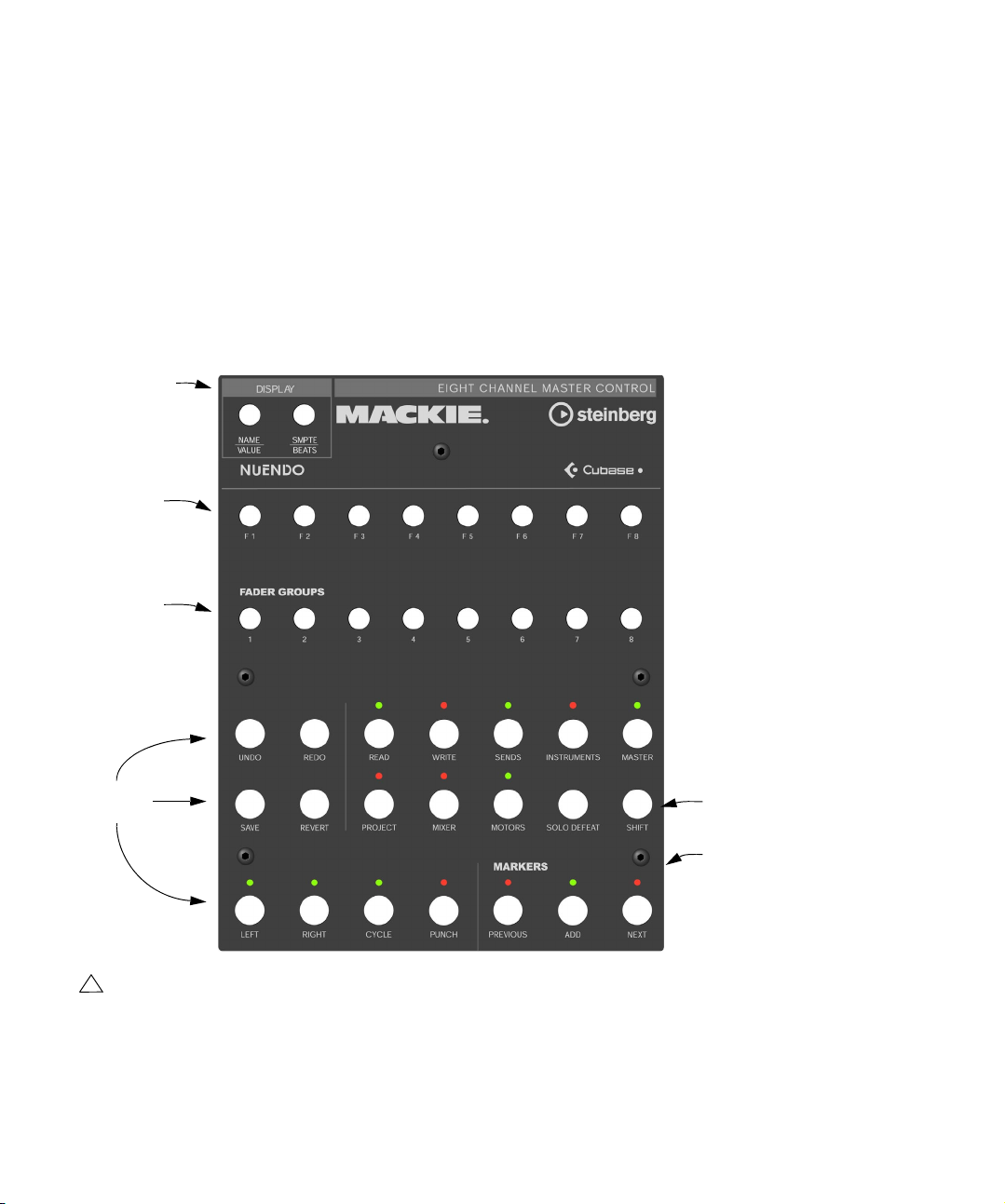
This chapter describes the Steinberg-specific layout for
Mackie Control, and also provides information regarding
the Mackie Control XT 8 channel extender unit.
Display section
Function keys
F1 to F8
Fader Groups
section
The Steinberg layout for Mackie Control
An overlay is included with your Mackie Control that
shows all Steinberg-specific key assignments for this device. The overlay can be placed over the top right part of
Mackie Control, above the transport controls. These key
assignments are used to remote control Cubase.
You can also order this overlay from Mackie. Contact your
hardware dealer for details.
The following figure shows the Steinberg overlay for
Mackie Control.
Action Keys
section
!
Please note that we will refer to the key assignments
of the Steinberg overlay throughout this manual, i.e.
the original key labels replaced by this overlay are not
used.
The Shift button
Markers section
6
Introduction
Page 7

About the Shift button
In the Action Keys section, to the right in the second row
of buttons, you will find the Shift button. The Shift button is
always used in combination with another button to extend
that button’s functionality. Pressing the Shift button alone
has no effect.
About Mackie Control XT
Mackie Control XT 8 channel extender units are also supported. All faders and encoder/displays are combined into
one continuous surface. The following applies:
• When the encoder section is used to display the data
for one channel (channel strip mode, or for plug-ins), the
parameters are presented over the encoder section of all
devices, from left to right.
• Fader bank navigation and encoder section assignment
is controlled by the Mackie Control unit.
• For each Mackie Control and Mackie Control XT unit, a
new device needs to be added in the Device Setup.
For each device select the appropriate MIDI ports.
• In the Device List, the top-most device represents the
right-most channels, and vice versa.
Please make sure that the used MIDI ports are deactivated in the “All
MIDI Inputs” device.
7
Introduction
Page 8

2
Basic mixing
Page 9
About this chapter
This chapter describes how to work with the faders and
the rows of buttons above them (Solo, Mute, Select and
Rec), and how to select which channels are affected by
the fader settings.
Selecting which channels to control
Mackie Control’s fader section controls eight different
channels in Cubase (plus the master level, which has its
own fader). You select which channels to control with the
aid of the Fader Banks section and the Fader Groups section of Mackie Control.
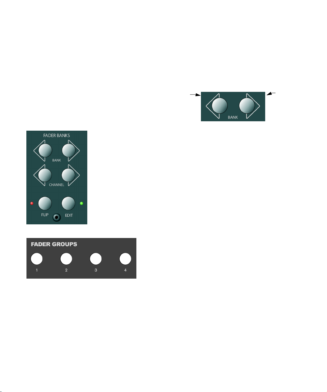
The Fader Banks section
Using the controls in the Fader Banks section
In the Fader Banks section, press the left or right Bank
button to switch from one set of eight channels to the
next. For example, if you are currently controlling Mixer
channels 1 to 8, pressing the right Bank button will switch
to the next eight channels, i.e. channels 9 to 16. To go
back to the previous eight channels, press the left Bank
button.
Selects the
previous eight
channels.
• If you press the left or right Channel button in the Fader
Banks section, the fader assignment will shift in steps of
one channel instead.
Let’s say the faders currently control audio channels 9-16. If you press
the left Channel button, the faders will shift one step to the left and control audio channels 8-15.
• Pressing the Flip button in the Fader Banks section
switches the parameter assignment between the faders
and the V-Pots, i.e. what was controlled with a fader is
now controlled with the corresponding V-Pot and vice
versa.
• Press the Edit button in the Fader Banks section to
open an editor for the current selection.
• Hold down Shift and press Edit to close the currently
active window.
Selects the
next eight
channels.
The Fader Groups section
Using the controls in the Fader Groups section
In Cubase, you can create so called channel view presets
in your Mixer window, by selecting the channels to be displayed and clicking the symbol button at the bottom left of
the Mixer window.
The Steinberg key assignments for Mackie Control make
use of the channel views feature. In the Fader Groups
section, the first channel view defined in Cubase is assigned to button 1, the second channel view is assigned
to button 2 and so on. In this way, you can switch between
any of the first eight channel views of Cubase by pressing
one of the buttons in the Fader Groups section.
9
Basic mixing
Page 10

Using the faders
The faders of Mackie Control are used for hands-on level
control and mixing, and allow precise adjustments of the
corresponding channel levels in Cubase. Since the faders
are motorized, they will move to reflect any level automation you have created in your projects. The faders will also
move when you select a new set of eight channels to control, instantly jumping to reflect the current levels of the
eight channels.
• The faders are also touch sensitive, which means that
as soon as you move a fader manually, the motors are
“overridden”.
In other words, if you have automated level changes, you can grab a
fader at any time, overriding the automation – just as you can click and
hold a moving fader on screen with the mouse.
• Even though the faders are very quiet, there may be situations when you want absolute silence – e.g. when mixing an extremely soft and subtle piece of music. If that is
the case, you can disable the motors by clicking the Motors button in the Action Keys section.
When you are finished, click the Motors button again. The fader motors
are enabled again, and the faders will instantly move to reflect the current
levels.
!
Turning the motors off does not affect the automation in Cubase – all automation data saved in your
project is played back as usual.
Rec/Rdy
The buttons directly underneath the row of V-Pots are
used to arm a track for recording. The LEDs indicate the
record arming state for a particular track.
The Signal LEDs underneath the Rec/Rdy buttons indicate signal activity on the channels. The LED lights up as
soon as the level meter for a channel shows any activity.
Mute and Solo
The two rows of buttons underneath the Rec/Rdy buttons
allow you to mute or solo channels. The following rules
apply:
• You can mute or solo several channels at the same time.
• The Mute and Solo buttons always show the status of
the current set of eight channels!
This means that if you mute a channel and then select another set of
eight channels for fader control, the Mute indicator will go dark.
!
If you have soloed a channel, this is indicated by the
Rude Solo LED at the top right of the Mackie Control
panel. You can un-solo or un-mute any channel or
combination of channels by pressing (without or with
Shift) the Solo Defeat button. See “Working with
windows” on page 26.
Using the Select buttons
In the rows of buttons above the faders you will find the
Select buttons. These are used for selecting a single
channel for detailed settings (see “Selected Channel
mode” on page 13).
• Only one channel at a time can be selected.
• When you solo a channel, it is automatically selected as
well.
• If you select a channel and then select another set of
eight channels for fader control, the Select button will go
dark.
This is because the channel is still selected, but it’s not shown in the current fader set.
10
Basic mixing
Page 11

A note about automation
The Read and Write buttons in the top row of the Action
Keys section control the status of the Read and Write buttons in the Mixer of Cubase, allowing remote control of
Mixer automation.
• Press the Read button to enable or disable the reading
of automation data for the selected channel.
• Hold down the Shift button and press the Read button
to enable or disable the reading of automation data for all
channels.
• Press the Write button to enable or disable the recording of automation data for the selected channel.
• Hold down the Shift button and press the Write button
to enable or disable the recording of automation data for
all channels.
11
Basic mixing
Page 12

3
Control strip assignment
Page 13

About this chapter
This chapter describes the assignment of the control strip
to access all VST settings in Cubase: EQ, effect sends,
effect and VST Instrument parameters and so on. It also
contains descriptions of the available parameter pages, as
shown in the display of Mackie Control.
Basic procedures
Selecting a parameter group
To be able to view the settings of a parameter in the display and edit the values with the V-Pots, you need to select the corresponding parameter group. This is done by
pressing one of the buttons in the Assignment and Action
Keys sections of Mackie Control.
About the three modes
Mackie Control operates in one of three modes: Selected
Channel, Fader Set or Global. Which mode is used depends on which parameter group is selected. For example, pushing the Pan button in the Assignment section
puts Mackie Control in Fader Set mode.
The functionality of the three modes is described on the
following pages.
Selected Channel mode
This mode gives you access to up to eight different parameters at the same time for a single, selected channel.
You can think of this as working with a single, vertical
channel strip on a mixer desk, having access to pan, EQ,
sends, etc. for a single channel.
When you have selected a parameter group in this mode,
the display shows the following information:
The upper row shows the names of the available parameters. Each
parameter can be controlled with the corresponding V-Pot. In this example, V-Pot 1 would control the “Freq1” parameter, V-Pot 2 would
control “Gain1” and so on.
The Action Keys section
The Assignment section
The name of the
selected parameter group.
• You select which channel to edit in Selected Channel
mode by pressing one of the eight Select buttons directly
above the faders.
See “Using the Select buttons” on page 10.
13
Control strip assignment
The selected
channel.
This indicates which page is shown,
and how many pages there are in
the selected parameter group. In
this example, the display shows
page 1 out of 2 pages.
Page 14

Fader Set mode
In this mode, you can view and edit a single parameter for
eight different channels (the current Fader Set). You can
think of this as working with a horizontal segment of a
mixer desk, e.g. the pan controls for eight consecutive
channels:
This indicates which page is
The name of the
selected parameter group.
The parameter available
for editing.
shown, and how many pages there
are in the selected parameter
group. In this example, the display
shows page 1 out of 2 pages.
The contents of the display depend on the selected parameter group. Here, the “Instruments” group is selected,
and the display shows settings for one of the active VST
Instruments:
The upper row shows the names of the available parameters. As you
can see, only four parameters are shown on one page, allowing longer
parameter names. Each parameter can be controlled with any of the
two V-Pots above it. Here, the “Octave” parameter would be controlled
with V-Pot 1 or 2, “Semitone” would be controlled with V-Pot 3 or 4
and so on.
The lower row shows the names of the eight channels in the current
Fader Set. You can control the selected parameter for each one of the
eight channels by using the corresponding V-Pot. In this example, VPot 1 would control the Pan parameter for the channel “Ch1”, V-Pot 2
would control the same parameter for the channel “Ch2” and so on.
• You select which set of eight channels to edit by using
the buttons in the Fader Banks and/or the Fader Groups
section, as described on “Selecting which channels to
control” on page 9.
Global mode
This is where you make global settings, i.e. settings that
are not related to the individual channels. Examples include parameter settings for the send effects, master effects and VST Instruments.
The name of the selected
parameter sub-group.
See “About parameter
sub-groups” on page 15
for an explanation of
parameter sub-groups.
The name
of the VST
Instrument.
This indicates which page is
shown, and how many pages
there are in the selected parameter group. In this example, the display shows page
2 out of 8 pages.
Using the control strip
When you have selected a parameter group (or parameter
sub-group – see below), you need to go to the page containing the desired parameter. This is done by pressing
the two buttons labeled I/O for Page Down and Sends for
Page Up at the top of the Assignment section.
• Holding down the Shift button (on the right in the second row of buttons in the Action Keys section) and pressing Page Up or Page Down takes you to the first or last
available parameter page.
Once the parameter is shown in the display, you can adjust its value by moving the corresponding V-Pot.
• When you move the V-Pot, the display will switch to
show the parameter values instead of the parameter
names.
After you have moved a V-Pot, the display will keep the values shown for
a short while before switching back to parameter names.
14
Control strip assignment
Page 15

• To view the parameter values without making any
changes, press the Name/Value button in the Display
section.
This makes the display switch to showing parameter values. Click the
N
ame/Value
button again to go back to parameter names.
• The parameter values are also indicated by the LED
rings around the V-Pots.
About parameter sub-groups
Most of the settings are structured in the following way: a
parameter group (accessed by pressing a button in the
Assignment or Action Keys sections) contains one or several pages, each holding one or several parameters.
However, in the case of send effects, master effects, instruments (Global mode) and inserts (Selected Channel
mode), there is one more hierarchical level, called a parameter sub-group. For example, the parameters for master effects are structured in the following way:
The “Master Effects” parameter group contains eight subgroups – one for each insert effect slot in Cubase. Each
sub-group contains a number of pages which contain a
number of parameters (both numbers depending on the
activated effects).
• To select another parameter sub-group, go to the first
page of the current sub-group and use V-Pot 1.
The figure below shows the first page of the first parameter sub-group in
the Master Effects group.
This indicates Master Effect slot 1. Use V-Pot 1 to select another parameter sub-group (i.e. another Master Effect slot).
About the symbols used in this chapter
On the following pages, all the different parameter groups
are described. The parameter groups are divided according to the three modes, Selected Channel, Fader Set and
Global.
For quick navigation in this manual, an icon at the top of
each manual page shows to which mode it belongs:
This icon indicates the “vertical” Selected Channel mode.
This icon indicates the “horizontal” Fader Set mode.
This icon indicates Global mode.
When a group of parameters has more than one page of
parameters in the Mackie Control display, this is indicated
by the following symbol:
This corresponds to the I/O and Sends buttons in the
Assignment section of Mackie Control.
For example, in the picture below, you would use the I/O
and Sends buttons to switch between the “Level” and the
“Enable” parameter pages:
15
Control strip assignment
Page 16

Selected Channel: EQ
Selected Channel: FX Send
Accessing the EQ controls for the currently selected
channel is achieved by pressing the EQ button in the Assignment section. If you press Shift + EQ one band per
page will be shown for the selected channel.
Please select a channel by pressing one of the Select buttons above the faders.
The controls for the equalizers are divided into 2 pages:
• Page 1
Frequency and Gain pairs for the four bands.
• Page 2
Enable and Q controls for the four bands.
Accessing the FX Send (auxiliary) controls for the currently selected channel is done by pressing the DYN button in the Assignment section. Pressing Shift+ DYN will
step through Fader Set mode “FX Send 1” to “FX Send
8”.
Please select a channel by pressing one of the Select buttons above the faders.
The controls for the sends are divided into 4 pages:
• Page 1
Send Levels for each of the 8 FX Sends.
• Page 2
Enable switches for each of the 8 FX Sends.
• Page 3
Switches to change between pre/post fader mode.
16
Control strip assignment
Page 17

• Page 4
Controls to choose the destination of the FX send signal.
!
The Bus destinations control whether the FX send
signal is sent directly to the internal effects, to the
Group channels or to a physical bus output (if your
sound card has additional outputs.)
Selected Channel: Inserts
Accessing the Insert Effect controls for the currently selected channel is done by pressing the Plug Ins button in
the Assignment section.
Please select a channel by pressing one of the Select buttons above the faders.
• When Page 01 is selected, V-Pot 1 selects which of the
insert slots is currently being edited (see “About parame-
ter sub-groups” on page 15).
If no effect is selected for the current insert slot, the display will show that ‘No Effect’ is selected.
After a plug-in has been selected in Cubase, the display
will change to show the selected plug-in in this effect slot
and the ‘number of pages’ indicator will be updated to
show the amount of pages necessary to display all the
plug-in’s declared parameters.
Here the Reverb32 plug-in has been selected.
17
Control strip assignment
Page 18

Selected Channel: Studio Sends
Selected Channel: Instruments
Accessing the Studio Sends controls for the currently selected channel is done by pressing the Sends and the
Shift button in the Action Keys section.
Please select a channel by pressing one of the Select buttons above the faders.
The controls for the Studio sends are divided into 4
pages:
• Page 1
Send Levels for each of the Studio Sends.
• Page 2
Enable switches for each of the Studio Sends.
• Page 3
Switches to change between pre/post fader mode.
• Page 4
Controls the left/right panning of the Studio send signal.
Accessing the Instrument controls for the currently selected channel is done by pressing the Instruments button
in the Action Keys section.
Please select a channel by pressing one of the Select buttons above the faders.
18
Control strip assignment
Page 19

Fader Set: Pan
Global: Send Effects
Accessing the Pan controls for the current Fader Set is
done by pressing the Pan button in the Assignment section.
The left/right panning of a channel in the current Fader Set
is controlled by the corressponding V-Pot.
Mackie Control can control the parameters of the effects
that are loaded in the first insert of FX channels. To access
these effects, press the Sends button in the Action Keys
section.
• When Page 01 is selected, V-Pot 1 selects which effect of the FX channels is currently being edited (see
“About parameter sub-groups” on page 15).
If no effect is selected for the current slot, the display will
show that ‘No Effect’ is selected.
After a plug-in has been selected in Cubase, the display
will change to show the currently selected plug-in this effect slot and the ‘number of pages’ indicator will be updated to show the amount of pages necessary to display
all the plug-in’s declared parameters.
Here the Reverb32 plug-in has been selected.
19
Control strip assignment
Page 20

Global: Master Effects
Global: Instruments
Mackie Control can control the parameters of the effects
that are loaded in the master effects section of the main
output. To access these effects, press the Master button
in the Action Keys section.
• When Page 01 is selected, V-Pot 1 selects which of the
master effect slots is currently being edited (see “About
parameter sub-groups” on page 15).
If no effect is selected for the current master effect slot,
the display will show that ‘No Effect’ is selected.
After a plug-in has been selected in Cubase, the display
will change to show the currently selected plug-in this effect slot and the ‘number of pages’ indicator will be updated to show the amount of pages necessary to display
all the plug-in’s declared parameters.
Here the Symphonic plug-in has been selected.
Mackie Control can control the parameters of the instruments that are loaded in the VST Instruments rack. To access these, push the Instruments button in the Action
Keys section and press Shift.
• When Page 01 is selected, V-Pot 1 selects which of the
VST Instrument slots is currently being edited (see “About
parameter sub-groups” on page 15).
If no VST Instrument is selected for the current slot the
display will read ‘No Effect’.
After an instrument plug-in has been selected in Cubase,
the display will change to show the currently selected instrument in this effect slot and the ‘number of pages’ indicator will be updated to show the amount of pages
necessary to display all the plug-in’s declared parameters.
20
Control strip assignment
Page 21

After an instrument plug-in has been selected in Cubase,
the display will change to show the currently selected instrument in this effect slot and the ‘number of pages’ indicator will be updated to show the amount of pages
necessary to display all the plug-in’s declared parameters.
21
Control strip assignment
Page 22

4
Transport control
Page 23

About this chapter
The transport controls
This chapter describes how to control playback, recording, positioning and the time display in Cubase from
Mackie Control.
Cursor keys, see “Cur-
sor keys” on page 27.
Fast Forward
Stop RecordRewind
The transport controls of Mackie Control are located in
the lower right corner of the panel:
Play
Jog Wheel
• Note that pressing Shift while pressing Rewind or Fast
Forward will move the project cursor to the beginning or
the end of the project.
About the jog wheel
The jog wheel will only move the project cursor position in
Cubase. If you press the Scrub button above the jog
wheel, the Cubase jog function will be used, i.e. you will
hear playback.
Transport control
Working with markers
23
Page 24

You can use Mackie Control to move directly to particular
positions defined in your project with the aid of markers.
Also, you can place such a marker at the current position in
the project. The most common use for this is probably to
move to the L and R markers – the left and right locators.
Jumping to a marker
In the Markers section (directly above the Transport Controls), press the Prev or Next button to jump from the current project cursor position to the previous or next marker
position in your project.
Adding a marker
1. Navigate the project cursor to the position where you
want to add a marker.
2. In the Markers section, press the Add button.
A
marker is placed at the current cursor position in your project.
Switching the time display
When you press the SMPTE/Beats button in the Display
section, the time display of Mackie Control will switch between “bars and beats” and the timecode format as selected in the project setup of Cubase.
This change is also reflected on the Transport bar of Cubase.
!
If you first change the time display on the Transport
bar in Cubase, this change is not reflected by Mackie
Control.
24
Transport control
Page 25

5
Other functions
Page 26

About this chapter
This chapter describes the remaining functions available
on the Mackie Control panel.
Project functions
The Save and Revert buttons in the Action Keys section of
the panel have the following functionality:
• Press the Save button to save the current project.
This is the same as selecting “Save” from the File menu in Cubase.
• Hold Shift and press Save to save a backup copy of the
current project.
This is the same as using the “Save New Version” command in Cubase.
• Press the Revert button to go back to the last saved
version of the current project.
This is the same as selecting “Revert” from the File menu in Cubase.
Edit functions
The Undo and Redo buttons in the Action Keys section of
the panel have the following functionality:
• Press Undo to undo the last operation in Cubase.
• Pressing Shift and Undo simultaneously opens the Edit
History dialog in Cubase.
• Press Redo to “undo the undo”.
Working with windows
The buttons above and to the left of the Markers section
allow you to control project functions or to open and close
windows in Cubase.
• Press the Left button to set the project cursor to the position marked by the left locator.
• Hold down Shift and press the Left button to move the
left locator to the current project cursor position.
• Press the Right button to set the project cursor to the
position marked by the right locator.
• Hold down Shift and press the Right button to move the
right locator to the current project cursor position.
• Press the Cycle button to switch Cycle mode on or off
in Cubase. This setting is reflected on the Transport bar in
Cubase.
• Press the Punch button to switch automatic punch in on
or off in Cubase. This setting is reflected on the Transport
bar in Cubase.
• Press the Project button to bring the current Project
window to the front.
• Press the Mixer button to open or close the Mixer window.
• Press the Motors button to switch on or off the faders’
motors – see “Using the faders” on page 10.
• Press the Solo Defeat button to disable Solo for all
channels.
• Hold down Shift and press the Solo Defeat button to
disable Mute for all channels.
26
Other functions
Page 27

In the top right corner of Mackie Control, next to the display, you will find an LED labeled Rude Solo. This LED
lights up as soon as any channel has been soloed.
The Rude Solo LED
Function keys
You can use the function keys F1 to F8 and function key
combinations with the Shift button to access functions in
Cubase. Refer to the Cubase operation manual for information about how to assign program functions to remote
controller function keys.
On the rear panel of Mackie Control you will find two input
jacks for foot pedals, labeled User Switch A and B.
Cursor keys
Pressing the cursor keys located to the left of the jog
wheel is the same as pressing the arrow keys on your
computer keyboard.
Showing level meters in the parameter display
You can show level meters for each channel in the parameter display. This is done by pressing Shift and the
SMPTE/Beats button. Pressing the same buttons again
reverts the display back to parameter mode.
The switches and inputs on the rear panel of Mackie Control
The procedure for assigning functions to these foot pedals is the same as for the function keys (see above).
Other functions
27
Page 28

Index
Page 29

B
Bank buttons 9
N
Name/Value button 15
C
Channel buttons 9
Control strip 14
Cursor keys 27
Cycle button 26
E
Edit button 9
Effects
Insert Effects 17, 18, 19
Master Effects 20
EQ
Selected Channel
mode 16, 18, 19, 20
F
Fader Set mode 14
Faders 10
Flip button 9
FX Send
Selected Channel
mode 16, 17, 18, 19, 20
G
Global mode 14
I
Inserts 17, 18, 19
Instruments 19, 20
O
Overlay 6
P
Page Up/Down buttons 14
Pan
Fader Set mode 18, 19
Parameter groups 13
Parameter sub-groups 15
Project button 26
Punch button 26
R
Read button 11
Rec/Rdy buttons 10
Redo button 26
Revert button 26
Right button 26
S
Save button 26
Select buttons
Selecting a channel for editing 10
Selected Channel mode 13
Sends
Selected Channel
mode 16, 17, 18, 19, 20
SMPTE/Beats button 24
Solo buttons 10
J
Jog wheel 23
L
Left button 26
Level meters 27
M
Mackie Control XT 7
Markers 23
Master Effects 20
Mixer button 26
Motors 10
Motors button 10
Mute buttons 10
T
Transport controls 23
U
Undo button 26
V
V-Pots 14
VST Instruments 19, 20
W
Wheel 23
Write button 11
29
Index
 Loading...