


 Loading...
PIX 270i
Rack Mount Production Video Recorder User Guide
Firmware rev. 2.10
E7556 State Rd. 23 and 33, Reedsburg, WI, USA |
www.sounddevices.com |
+1 (608) 524-0625 • Toll-Free: (800) 505-0625 • fax: +1 (608) 524-0655 |
support@sounddevices.com |

PIX 270i User Guide and Technical Information
Table of Contents
Introduction |
|
|
1 |
Manual Conventions .. . . . . . . . . . . . . . . . . . . . . . . . . . . . |
. 1 |
Video Mode and Audio Mode.. . . . . . . . . . . . . . . . . . . . |
. 1 |
Panel Descriptions |
|
|
2 |
Front Panel..................................... |
. 2 |
PIX-CADDY 2 (Optional).......................... |
. 5 |
Rear Panel.. . . . . . . . . . . . . . . . . . . . . . . . . . . . . . . . . . . . . |
. 3 |
|
|
Menu and Navigation |
|
|
6 |
Main View.. . . . . . . . . . . . . . . . . . . . . . . . . . . . . . . . . . . . . |
. 6 |
File List.. . . . . . . . . . . . . . . . . . . . . . . . . . . . . . . . . . . . . . . . |
. 9 |
Menu . . . . . . . . . . . . . . . . . . . . . . . . . . . . . . . . . . . . . . . . . |
. 7 |
Metadata Screen. . . . . . . . . . . . . . . . . . . . . . . . . . . . . . . |
. 11 |
Audio Screen.. . . . . . . . . . . . . . . . . . . . . . . . . . . . . . . . . . . |
. 8 |
LCD.. . . . . . . . . . . . . . . . . . . . . . . . . . . . . . . . . . . . . . . . . . |
. 12 |
Inputs and Outputs |
|
|
13 |
Video Inputs .. . . . . . . . . . . . . . . . . . . . . . . . . . . . . . . . . . |
. 13 |
Audio Inputs.. . . . . . . . . . . . . . . . . . . . . . . . . . . . . . . . . . |
. 14 |
Video Outputs. . . . . . . . . . . . . . . . . . . . . . . . . . . . . . . . . |
. 13 |
Audio Outputs................................. |
. 18 |
Ethernet |
|
|
19 |
Video Monitoring Features |
|
20 |
|
Exposure Assist.. . . . . . . . . . . . . . . . . . . . . . . . . . . . . . . . |
. 20 |
Zoom .. . . . . . . . . . . . . . . . . . . . . . . . . . . . . . . . . . . . . . . . |
. 24 |
Focus Assist .. . . . . . . . . . . . . . . . . . . . . . . . . . . . . . . . . . . |
. 22 |
Flip Display. . . . . . . . . . . . . . . . . . . . . . . . . . . . . . . . . . . . |
. 24 |
Recording |
|
|
25 |
Sound Devices File Format. . . . . . . . . . . . . . . . . . . . . . . |
. 25 |
Interruption of Signal During Recording. . . . . . . . . . . |
. 27 |
File Splitting. . . . . . . . . . . . . . . . . . . . . . . . . . . . . . . . . . . |
. 26 |
Alignment of Audio and Video .. . . . . . . . . . . . . . . . . . |
. 27 |
False Take. . . . . . . . . . . . . . . . . . . . . . . . . . . . . . . . . . . . . |
. 26 |
Audio Track Arming .. .. .. .. .. .. .. .. .. .. .. .. .. .. .. .. .. .. .. .. .. .. .. .. .. .. .. .. |
.. 28 |
Selecting Video File Resolution and Frame Rate .. . . . |
. 26 |
Audio Mode .. . . . . . . . . . . . . . . . . . . . . . . . . . . . . . . . . . |
. 28 |
Selecting a Video Codec .. . . . . . . . . . . . . . . . . . . . . . . . |
. 27 |
F Sampling Rate Modes.. . . . . . . . . . . . . . . . . . . . . . . . . |
. 30 |
Video Scaling and Frame Rate Conversion |
31 |
||
Up and Down Conversion.. . . . . . . . . . . . . . . . . . . . . . . |
. 32 |
|
|
Playback |
|
|
34 |
Playback Operation .. . . . . . . . . . . . . . . . . . . . . . . . . . . . |
. 34 |
Looping Playback.. . . . . . . . . . . . . . . . . . . . . . . . . . . . . . |
. 36 |
Shuttle Playback Mode .. . . . . . . . . . . . . . . . . . . . . . . . . |
. 35 |
Playback Mode.. . . . . . . . . . . . . . . . . . . . . . . . . . . . . . . . |
. 36 |
Cue Marker.. . . . . . . . . . . . . . . . . . . . . . . . . . . . . . . . . . . |
. 35 |
Play List....................................... |
. 37 |
Table of Contents
i

PIX 270i User Guide and Technical Information
Playback Rate of Audio Files.. . . . . . . . . . . . . . . . . . . . . |
. 38 |
Playing Back Files on a Computer .. . . . . . . . . . . . . . . . |
. 38 |
Non-Native File Playback.. . . . . . . . . . . . . . . . . . . . . . . . |
. 38 |
|
|
Synchronization and Timecode |
39 |
||
Sync Reference .. . . . . . . . . . . . . . . . . . . . . . . . . . . . . . . . |
. 40 |
Timecode Reader .. . . . . . . . . . . . . . . . . . . . . . . . . . . . . . |
. 41 |
Internal Ambient® Lockit: Timecode Generator with Sync
Out.. . . . . . . . . . . . . . . . . . . . . . . . . . . . . . . . . . . . . . . . . . |
. 41 |
Timecode Modes. . . . . . . . . . . . . . . . . . . . . . . . . . . . . . . |
. 42 |
Timecode Frame Rate. . . . . . . . . . . . . . . . . . . . . . . . . . . |
. 42 |
Timecode Input Sources. . . . . . . . . . . . . . . . . . . . . . . . . |
. 43 |
Synchronization/Timecode Examples. . . . . . . . . . . . . . |
. 43 |
Powering |
|
|
46 |
PowerSafe.. . . . . . . . . . . . . . . . . . . . . . . . . . . . . . . . . . . . |
. 46 |
|
|
Network Grouping |
|
|
47 |
Grouped Settings.. . . . . . . . . . . . . . . . . . . . . . . . . . . . . . |
. 47 |
Group Auto-Configuration.. . . . . . . . . . . . . . . . . . . . . . |
. 48 |
Pushing Settings to Group. . . . . . . . . . . . . . . . . . . . . . . |
. 48 |
Grouped Transport.. . . . . . . . . . . . . . . . . . . . . . . . . . . . . |
. 48 |
Contents of Table
ii
External Control |
|
|
50 |
RS-422. . . . . . . . . . . . . . . . . . . . . . . . . . . . . . . . . . . . . . . . |
. 50 |
Triggering Recording from SDI Flag Bits.. . . . . . . . . . . |
. 57 |
Web Interface - PIXNET.. . . . . . . . . . . . . . . . . . . . . . . . . |
. 50 |
GPIO (General Purpose Input / Output).. . . . . . . . . . . . |
. 57 |
PIXNET Unit Page Main View and Menu Tabs .. . . . . . |
. 54 |
USB Keyboard.. . . . . . . . . . . . . . . . . . . . . . . . . . . . . . . . . |
. 58 |
Triggering Recording from External Timecode. . . . . . |
. 56 |
|
|
Storage and File Management |
59 |
||
Storage.. . . . . . . . . . . . . . . . . . . . . . . . . . . . . . . . . . . . . . |
. 59 |
Audio File Metadata............................ |
. 62 |
Metadata.. . . . . . . . . . . . . . . . . . . . . . . . . . . . . . . . . . . . . |
. 61 |
File Management.. . . . . . . . . . . . . . . . . . . . . . . . . . . . . . |
. 64 |
Setup Management and Firmware Upgrades |
68 |
||
Saving and Loading Setup Files................... |
. 68 |
Factory Restore.. . . . . . . . . . . . . . . . . . . . . . . . . . . . . . . . |
. 70 |
Custom Defaults and Setup Menu Option Visibility.. . 68 |
Firmware Upgrades .. . . . . . . . . . . . . . . . . . . . . . . . . . . . |
. 70 |
|
Setup Menu Options |
|
|
71 |
File Storage.. . . . . . . . . . . . . . . . . . . . . . . . . . . . . . . . . . . |
. 71 |
On-Screen Display. . . . . . . . . . . . . . . . . . . . . . . . . . . . . . |
. 78 |
Video .. . . . . . . . . . . . . . . . . . . . . . . . . . . . . . . . . . . . . . . . |
. 72 |
Remote Control................................ |
. 79 |
Audio.. . . . . . . . . . . . . . . . . . . . . . . . . . . . . . . . . . . . . . . . |
. 73 |
Network.. . . . . . . . . . . . . . . . . . . . . . . . . . . . . . . . . . . . . . |
. 79 |
Timecode/Sync.. . . . . . . . . . . . . . . . . . . . . . . . . . . . . . . . |
. 75 |
System .. . . . . . . . . . . . . . . . . . . . . . . . . . . . . . . . . . . . . . . |
. 80 |
LCD Monitor.. . . . . . . . . . . . . . . . . . . . . . . . . . . . . . . . . . |
. 77 |
Quick Setup.. . . . . . . . . . . . . . . . . . . . . . . . . . . . . . . . . . . |
. 81 |
Button Shortcuts |
|
|
81 |
Connector Pin Assignments |
|
82 |
|
Appendix A - Supported Files |
85 |
||
v. 2.10 Features and specifications are subject to change. Visit www.sounddevices.com for the latest documentation.

|
PIX 270i User Guide and Technical Information |
|
Specifications |
86 |
|
SDI. . . . . . . . . . . . . . . . . . . . . . . . . . . . . . . . . . . . . . . . . . . |
. 86 |
HDMI .. . . . . . . . . . . . . . . . . . . . . . . . . . . . . . . . . . . . . . . . |
. 86 |
Video Input Resolutions / Rates.. .. .. .. .. .. .. .. .. .. .. .. .. .. .. .. .. .. .. .. 86 |
|
Video Codecs and Files. . . . . . . . . . . . . . . . . . . . . . . . . . |
. 86 |
Up/Down/Cross Conversion.. . . . . . . . . . . . . . . . . . . . . . |
. 86 |
Frame Rate Conversion .. . . . . . . . . . . . . . . . . . . . . . . . . |
. 86 |
LCD.. . . . . . . . . . . . . . . . . . . . . . . . . . . . . . . . . . . . . . . . . . |
. 86 |
Audio Recording and Playback. . . . . . . . . . . . . . . . . . . |
. 87 |
Analog Audio.. . . . . . . . . . . . . . . . . . . . . . . . . . . . . . . . . |
. 87 |
Digital Audio.. . . . . . . . . . . . . . . . . . . . . . . . . . . . . . . . . . |
. 87 |
File Storage.. . . . . . . . . . . . . . . . . . . . . . . . . . . . . . . . . . . |
. 87 |
Timecode and Sync.. . . . . . . . . . . . . . . . . . . . . . . . . . . . . |
. 88 |
Control.. . . . . . . . . . . . . . . . . . . . . . . . . . . . . . . . . . . . . . . |
. 88 |
Keyboard.. . . . . . . . . . . . . . . . . . . . . . . . . . . . . . . . . . . . . |
. 88 |
Power.. . . . . . . . . . . . . . . . . . . . . . . . . . . . . . . . . . . . . . . . |
. 88 |
Physical. . . . . . . . . . . . . . . . . . . . . . . . . . . . . . . . . . . . . . . |
. 88 |
Declaration of Conformity
Software License
Warranty and Technical Support
89
90
91
Table of Contents
iii

PIX 270i User Guide and Technical Information
Copyright Notice and Release
Contents of Table
iv
All rights reserved. No part of this publication may be reproduced, stored in a retrieval system, or transmitted in any form or by any means, electronic, mechanical, photocopying, recording, or otherwise, without the expressed written permission of SOUND DEVICES, LLC. SOUND DEVICES is not responsible for any use of this information.
Microsoft Windows is a registered trademark of Microsoft Corporation. Macintosh, OSX, and ProRes are registered trademarks of Apple, Inc. DNxHD is a registered trademark of Avid, Inc. Other product and company names mentioned herein may be the trademarks of their respective owners.
PIX 270i, and the sound waves logo are registered trademarks of Sound Devices, LLC.
Limitation of Liability
LIMITATION ON SOUND DEVICES’ LIABILITY. SOUND DEVICES, LLC SHALL NOT BE LIABLE TO THE PURCHASER OF THIS PRODUCT OR THIRD PARTIES FOR DAMAGES, LOSSES, COSTS, OR EXPENSES INCURRED BY PURCHASER OR THIRD PARTIES AS A RESULT OF: ACCIDENT, MISUSE, OR ABUSE OF THIS PRODUCT OR UNAUTHORIZED MODIFICATIONS, REPAIRS, OR ALTERATIONS TO THIS PRODUCT, OR FAILURE TO STRICTLY COMPLY WITH SOUND DEVICES, LLC’S OPERATING AND INSTALLATION INSTRUCTIONS. TO THE FULLEST EXTENT PERMITTED BY LAW, SOUND DEVICES SHALL HAVE NO LIABILITY TO THE END USER OR ANY OTHER PERSON FOR COSTS, EXPENSES, DIRECT DAMAGES, INCIDENTAL DAMAGES, PUNITIVE DAMAGES, SPECIAL DAMAGES, CONSEQUENTIAL DAMAGES OR OTHER DAMAGES OF ANY KIND OR NATURE WHATSOEVER ARISING OUT OF OR RELATING TO THE PRODUCTS, THESE TERMS AND CONDITIONS OR THE PARTIES’ RELATIONSHIP, INCLUDING, WITHOUT LIMITATION, DAMAGES RESULTING FROM OR RELATED TO THE DELETION OR OTHER LOSS OF AUDIO OR VIDEO RECORDINGS OR DATA, REDUCED OR DIMINISHED AUDIO OR VIDEO QUALITY OR OTHER SIMILAR AUDIO OR VIDEO DEFECTS ARISING FROM, RELATED TO OR OTHERewISE ATTRIBUTABLE TO THE PRODUCTS OR THE END USER’S USE OR OPERATION THEREOF, REGARDLESS OF WHETHER SUCH DAMAGES ARE CLAIMED UNDER CONTRACT, TORT OR ANY OTHER THEORY. “CONSEQUENTIAL DAMAGES” FOR WHICH SOUND DEVICES SHALL NOT BE LIABLE SHALL INCLUDE, WITHOUT LIMITATION, LOST PROFITS, PENALTIES, DELAY DAMAGES, LIQUIDATED DAMAGES AND OTHER DAMAGES AND LIABILITIES WHICH END USER SHALL BE OBLIGATED TO PAY OR WHICH END USER OR ANY OTHER PARTY MAY INCUR RELATED TO OR ARISING OUT OF ITS CONTRACTS WITH ITS CUSTOMERS OR OTHER THIRD PARTIES. NOTWITHSTANDING AND WITHOUT LIMITING THE FOREGOING, IN NO EVENT SHALL SOUND DEVICES BE LIABLE FOR ANY AMOUNT OF DAMAGES IN EXCESS OF AMOUNTS PAID BY THE END USER FOR THE PRODUCTS AS TO WHICH ANY LIABILITY HAS BEEN DETERMINED TO EXIST. SOUND DEVICES AND END USER EXPRESSLY AGREE THAT THE PRICE FOR THE PRODUCTS WAS DETERMINED IN CONSIDERATION OF THE LIMITATION ON LIABILITY AND DAMAGES SET FORTH HEREIN AND SUCH LIMITATION HAS BEEN SPECIFICALLY BARGAINED FOR AND CONSTITUTES AN AGREED ALLOCATION OF RISK WHICH SHALL SURVIVE THE DETERMINATION OF ANY COURT OF COMPETENT JURISDICTION THAT ANY REMEDY HEREIN FAILS OF ITS ESSENTIAL PURPOSE.
v. 2.10 Features and specifications are subject to change. Visit www.sounddevices.com for the latest documentation.

PIX 270i User Guide and Technical Information
Introduction
The PIX 270i is a rack-mountable, production video recorder with extensive audio and video processing capabilities. The foundation of the PIX 270i is hardware-based, 10-bit video up/down/cross conversion, and hardware-based encoding to Apple ProRes and Avid DNxHD codecs. These features allow for fast, reliable acquisition of video (at any standard HD or SD resolution and frame rate) and audio (up to 64 tracks from Analog, AES, HDMI, SDI, MADI, or Dante sources) to ready-for-edit, industry standard QuickTime .mov files.
Files are recorded simultaneously on (up to) 4 separate, 2.5” SSD storage devices via two front panel PIX-CADDY slots and two rear panel eSATAp connections. This redundancy in local, removable storage devices, coupled with standard, Ethernet-based file transfer features further reduces steps in the production workflow. Gigabit Ethernet network ports enable remote access to recorded files and the ability to transfer them quickly into a post-production environment.
Full-featured precision timecode and sync reference I/O using Ambient Clockit core technology is provided to allow tight synchronization with external equipment in complex multi-machine configurations. The PIX 270i supports various external control options: RS-422, GPIO, SDI flags, Timecode triggering, and an embedded web server for network-based remote control. Network Grouping functionality enables linked, frame-synchronized recording and playback of multiple PIX 270i units connected to a standard Ethernet network.
This User Guide details installation and operation of the PIX 270i. This User Guide corresponds to PIX 270i firmware version 2.10. User Guide revisions are released at the same time as firmware updates and available online:
http://www.sounddevices.com/products/pix270i/downloads/
Manual Conventions
Several formatting features have been included to make navigating the guide easier.
•Physical buttons on the PIX 270i are represented with capital letters (REC button, MENU, etc). All physical button names are detailed in the Panel Descriptions section.
•Button combinations are represented with the plus (+) symbol. For example: “Press LCD + AUDIO” means to first hold down LCD, then press AUDIO, and finally release both buttons.
•Setup Menu items are indicated with this text: [Menu Category - Parameter], where the menu category is one of the items in the list displayed when MENU is pushed, and the parameter is an item in the list displayed when that category is selected (by pressing in on the Control Knob).
•Blue italicized text references sections of the user guide containing contextually relevant information. When viewing this document on a computer, this text can be clicked to jump to the named section.
Video Mode and Audio Mode
Throughout this User Guide, the terms Video Mode and Audio Mode will be used. The PIX 270i is capable of recording video and audio together into a QuickTime .mov file (Video Mode) or recording audio only to a .wav file (Audio Only Mode). The mode is determined by the Setup Menu option
[System - Video/Audio Mode]. When set to [Video + Audio (QuickTime), the PIX 270i is in Video Mode. When set to Audio Only Poly (Wave) or Audio Only Mono (Wave) the PIX 270i is in Audio Mode.
Introduction
1
PIX 270i User Guide and Technical Information
Panel Descriptions
Front Panel
1 |
|
|
|
|
2 |
|
|
3 |
4 |
5 |
6 |
|
|
7 |
8 |
|
|
|
9 |
|
|
|
|
|
||||||||||||||||||||||||||||
|
|
|
|
|
|
|
|
|
|
|
|
|
|
|
|
|
|
|
|
|
|
|
|
|
|
|
|
|
|
|
|
|
|
|
|
|
|
|
|
|
|
|
|
|
|
|
|
|
|
|
|
|
|
|
|
|
|
|
|
|
|
|
|
|
|
|
|
|
|
|
|
|
|
|
|
|
|
|
|
|
|
|
|
|
|
|
|
|
|
|
|
|
|
|
|
|
|
|
|
|
|
|
|
|
|
|
|
|
|
|
|
|
|
|
|
|
|
|
|
|
|
|
|
|
|
|
|
|
|
|
|
|
|
|
|
|
|
|
|
|
|
|
|
|
|
|
|
|
|
|
|
|
|
|
|
|
|
|
|
|
|
|
|
|
|
|
|
|
|
|
|
|
|
|
|
|
|
|
|
|
|
|
|
|
|
|
|
|
|
|
|
|
|
|
|
|
|
|
|
|
|
|
|
|
|
|
|
|
|
|
|
|
|
|
|
|
|
|
|
|
|
|
|
|
|
|
|
|
|
|
|
|
|
|
|
|
|
|
|
|
|
|
|
|
|
|
|
|
|
|
|
|
|
|
|
|
|
|
|
|
|
|
|
|
|
|
|
|
|
|
|
|
|
|
|
|
|
|
|
|
|
|
|
|
|
|
|
|
|
|
|
|
|
|
|
|
|
|
|
|
|
|
|
|
|
|
|
|
|
|
|
|
|
|
|
|
|
|
|
|
|
|
|
|
|
|
|
|
|
|
|
|
|
|
|
|
|
|
|
|
|
|
|
|
|
|
|
|
|
|
|
|
|
|
|
|
|
|
|
|
|
|
|
|
|
|
|
|
|
|
|
|
|
|
|
|
|
|
|
|
|
|
|
|
|
|
|
|
|
|
|
|
|
|
|
|
|
|
|
|
|
|
|
|
|
|
|
|
|
|
|
|
|
|
|
|
|
|
|
|
|
|
|
|
|
|
|
|
|
|
|
|
|
|
|
|
|
|
|
|
|
|
|
|
|
|
|
|
|
|
|
|
|
|
|
|
|
|
|
|
|
|
|
|
|
|
|
|
|
|
|
|
|
|
|
|
|
|
|
|
|
|
|
|
|
|
|
|
|
|
|
|
|
|
|
|
|
|
|
|
|
|
|
|
|
|
|
|
|
|
|
|
|
|
|
|
|
|
|
|
|
|
|
|
|
|
|
|
|
|
|
|
|
|
|
|
|
|
|
|
|
|
|
|
|
|
|
|
|
|
|
|
|
|
|
|
|
|
|
|
|
|
|
|
|
|
|
|
|
|
|
|
|
|
|
|
|
|
|
|
|
|
|
|
|
|
|
|
|
|
|
|
|
|
|
|
|
|
|
|
|
|
|
|
|
|
|
|
|
|
|
|
|
|
|
|
|
|
|
|
|
|
|
|
|
|
|
|
|
|
|
|
|
|
|
|
|
|
|
|
|
|
|
|
|
|
|
|
|
|
|
|
|
|
|
|
|
|
|
|
|
|
|
|
|
|
|
|
|
|
|
|
|
|
|
|
|
|
|
|
|
|
|
|
|
|
|
|
|
|
|
|
|
|
|
|
|
|
|
|
|
|
|
|
|
|
|
|
|
|
|
|
|
|
|
|
|
|
|
|
|
|
|
|
|
|
|
|
|
|
|
|
|
|
|
|
|
|
|
|
|
|
|
|
|
|
|
|
|
|
|
|
|
|
|
|
|
|
|
|
|
|
|
|
|
|
|
|
|
|
|
|
|
|
|
|
|
|
|
|
|
|
|
|
|
|
|
|
|
|
|
|
|
|
|
|
|
|
|
|
|
|
|
|
|
|
|
|
|
|
|
|
|
|
|
|
|
|
|
|
|
|
|
|
|
|
|
|
|
|
|
|
|
|
|
|
|
|
|
|
|
|
|
|
|
|
|
|
|
|
|
|
|
|
|
|
|
|
|
|
|
|
|
|
|
|
|
|
|
|
|
|
|
|
|
|
|
|
|
|
|
|
|
|
|
|
|
|
|
|
|
|
|
|
|
|
|
|
|
|
|
|
|
|
|
|
|
|
|
|
|
|
|
|
|
|
|
|
|
|
|
|
|
|
|
|
|
|
|
|
|
|
|
|
|
|
|
|
|
|
|
|
|
|
|
|
|
|
|
|
|
|
|
|
|
|
|
|
|
|
|
|
|
|
|
|
|
|
|
|
|
|
|
|
|
|
|
|
|
|
|
|
|
|
|
|
|
|
|
|
|
|
|
|
|
|
|
|
|
|
|
|
|
|
|
|
|
|
|
|
|
|
|
|
|
|
|
|
|
|
|
|
|
|
|
|
|
|
|
|
|
|
|
|
|
|
|
|
|
|
|
|
|
|
|
|
|
|
|
|
|
|
|
|
|
|
|
|
|
|
|
|
|
|
|
|
|
|
|
|
|
|
|
|
|
|
|
|
|
|
|
|
|
|
|
|
|
|
|
|
|
|
|
|
|
|
|
|
|
|
|
|
|
|
|
|
|
|
|
|
|
|
|
|
|
|
|
|
|
|
|
|
|
|
|
|
|
|
|
|
|
|
|
|
|
|
|
|
|
|
|
|
|
|
|
|
|
|
|
|
|
|
|
|
|
|
|
|
|
|
|
|
|
|
|
Descriptions Panel
15 |
14 |
13 |
12 |
11 |
10 |
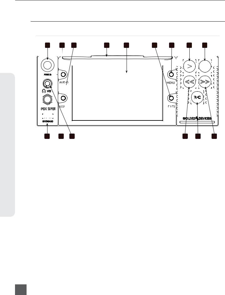
1)Control Knob
The Control Knob can be both turned and pressed. Use the Control Knob to navigate between menu settings and to select menu items. Pressing during playback or stop will toggle Shuttle mode. Turning while playback is paused will jog forward or backward by single frames.
2)AUDIO Button
Displays the Audio Screen. From the Audio Screen: Select audio input sources, Arm/disarm tracks, Set audio input gain and delay, View audio input levels, and Edit audio track names.
3)LCD Button
Toggles the On-Screen Display. Hold for 2 seconds to toggle LCD on/off. Press to return to the Main View.
4)Handle
This handle is designed to provide a gripping point for tilting down the LCD.
5)LCD Display
Displays operating information when the On-Screen Display (OSD) is active(See “On-Screen Display”, page 6), user interface, source video, and playback video. 5-inch display; 800x480 resolution.
6)FILES Button
Displays the File List View. Press FILES + Fast Forward (>>) during record or playback to add a Cue Marker. Press FILES + Rewind (<<) to delete a Cue Marker.
7)MENU Button
Displays the Setup Menu.
8)Play Button
Plays the most recently recorded file when pressed. In the File List View, plays the selected file from the File List. Toggles Play and Pause in Playback mode. Press and hold Play to activate Loop Play (Video Mode). (See “Playback”, page 34)
9)Stop Button
Stops an active recording or playback. When Stopped, hold the Stop button to display the next filename.
2
v. 2.10 Features and specifications are subject to change. Visit www.sounddevices.com for the latest documentation.

PIX 270i User Guide and Technical Information
10)Fast Forward Button
When Stopped, press to cue up the next file for Playback. During Playback or Pause, press once to jump to the next Cue Marker, press and hold to increase playback speed. Continue to hold for faster speeds.
11)REC Button
Begins recording. Optional: Splits the recording and begins writing a new file when pressed while recording.
[System - Rec Button File Split]
12)Rewind Button
When Stopped, press to cue up the previous file for Playback. During Playback and Pause, press once to jump to the previous Cue Marker or beginning of the file, press and hold to reverse playback speed. Continue to hold for faster reverse speeds.
13)Headphone Volume Knob
Adjusts the overall volume of the headphones. NOTE: the headphone output is capable of ear-damaging levels. Take care when adjusting among signal sources.
14)Headphone Output 1/4”
TRS stereo headphone connector. Can drive headphones from 8 to 100 ohms to very high headphone levels.
15)USB Keyboard Input
USB A female connector to connect a USB keyboard. Keyboards can be used to navigate, control, and enter metadata into the PIX 270i. Keyboards with integrated USB hubs are not compatible.
Rear Panel
2 |
|
3 |
|
4 |
|
5 |
|
6 |
|
7 |
8 |
|
|
|
|
|
|
|
|
9 |
10 |
|
|
|
|
|
|
|
|
|||||||||||||||||||||||||||||||||||
|
|
|
|
|
|
|
|
|
|
|
|
|
|
|
|
|
|
|
|
|
|
|
|
|
|
|
||||||||||||||||||||||||||||||||||||||
|
|
|
|
|
|
|
|
|
|
|||||||||||||||||||||||||||||||||||||||||||||||||||||||
|
|
|
|
|
|
|
|
|
|
|
|
|
|
|
|
|
|
|
|
|
|
|
|
|
|
|
|
|
|
|
|
|
|
|
|
|
|
|
|
|
|
|
|
|
|
|
|
|
|
|
|
|
|
|
|
|
|
|
|
|
|
|
|
|
|
|
|
|
|
|
|
|
|
|
|
|
|
|
|
|
|
|
|
|
|
|
|
|
|
|
|
|
|
|
|
|
|
|
|
|
|
|
|
|
|
|
|
|
|
|
|
|
|
|
|
|
|
|
|
|
|
|
|
|
|
|
|
|
|
|
|
|
|
|
|
|
|
|
|
|
|
|
|
|
|
|
|
|
|
|
|
|
|
|
|
|
|
|
|
|
|
|
|
|
|
|
|
|
|
|
|
|
|
|
|
|
|
|
|
|
|
|
|
|
|
|
|
|
|
|
|
|
|
|
|
|
|
|
|
|
|
|
|
|
|
|
|
|
|
|
|
|
|
|
|
|
|
|
|
|
|
|
|
|
|
|
|
|
|
|
|
|
|
|
|
|
|
|
|
|
|
|
|
|
|
|
|
|
|
|
|
|
|
|
|
|
|
|
|
|
|
|
|
|
|
|
|
|
|
|
|
|
|
|
|
|
|
|
|
|
|
|
|
|
|
|
|
|
|
|
|
|
|
|
|
|
|
|
|
|
|
|
|
|
|
|
|
|
|
|
|
|
|
|
|
|
|
|
|
|
|
|
|
|
|
|
|
|
|
|
|
|
|
|
|
|
|
|
|
|
|
|
|
|
|
|
|
|
|
|
|
|
|
|
|
|
|
|
|
|
|
|
|
|
|
|
|
|
|
|
|
|
|
|
|
|
|
|
|
|
|
|
|
|
|
|
|
|
|
|
|
|
|
|
|
|
|
|
|
|
|
|
|
|
|
|
|
|
|
|
|
|
|
|
|
|
|
|
|
|
|
|
|
|
|
|
|
|
|
|
|
|
|
|
|
|
|
|
|
|
|
|
|
|
|
|
|
|
|
|
|
|
|
|
|
|
|
|
|
|
|
|
|
|
|
|
|
|
|
|
|
|
|
|
|
|
|
|
|
|
|
|
|
|
|
|
|
|
|
|
|
|
|
|
|
|
|
|
|
|
|
|
|
|
|
|
|
|
|
|
|
|
|
|
|
|
|
|
|
|
|
|
|
|
|
|
|
|
|
|
|
|
|
|
|
|
|
|
|
|
|
|
|
|
|
|
|
|
|
|
|
|
|
|
|
|
|
|
|
|
|
|
|
|
|
|
|
|
|
|
|
|
|
|
|
|
|
|
|
|
|
|
|
|
|
|
|
|
|
|
|
|
|
|
|
|
|
|
|
|
|
|
|
|
|
|
|
|
|
|
|
|
|
|
|
|
|
|
|
|
|
|
|
|
|
|
|
|
|
|
|
|
|
|
|
|
|
|
|
|
|
|
|
|
|
|
|
|
|
11
1
Panel Descriptions
19 |
18 |
17 |
16 |
15 |
14 |
13 |
12 |
1) Secondary DC Power Input (XLR 4-pin) |
3) MADI I/O (SC Optical) |
|
Accepts 10–27 volts DC. XLR 4-pin con- |
Input (top) accepts up to 64 channels of |
|
nector is wired pin-1 ground, pin-4 posi- |
MADI (AES10) digital audio. Output |
|
tive (+). |
(bottom) provides MADI (AES10) digital. |
|
2) Primary DC Power Input (XLR 4-pin) |
MADI connections use multimode fiber |
|
and networks. |
||
Accepts 10–27 volts DC. XLR 4-pin con- |
||
|
||
nector is wired pin-1 ground, pin-4 posi- |
|
|
tive (+). |
|
3

PIX 270i User Guide and Technical Information
Descriptions Panel
4)MADI I/O (BNC)
Input (top) accepts up to 64 channels of MADI (AES10) digital audio. Output (bottom) provides MADI (AES10) digital audio.
5)Timecode I/O (BNC)
Input (top) accepts SMPTE timecode. Output (bottom) provides SMPTE timecode.
6)SYNC I/O (BNC)
Output (bottom): Selectable genlock or wordclock output. Configured with Setup Menu option
[Timecode/Sync - Sync Out]. Input (top): Selectable Genlock or Wordclock input. Configured with [Timecode/Sync] Setup Menu options Sync Ref - Video Playback or Sync Ref - Audio Playback.
7)Digital Audio AES I/O (DB-25)
8 channels of AES digital audio input and 8 channels of AES digital output. (See “Connector Pin Assignments”, page 82)
8)Ch. 1-8 Analog Audio Output (DB-25)
8 channels of balanced, line-level analog audio output. Configured with Setup Menu option [Audio - Line Output]. (See “Connector Pin Assignments”, page 82)
9)Ch. 1-8 Analog Audio Input (DB-25)
8 channels of balanced, line-level analog audio input. (See “Connector Pin Assignments”, page 82)
10)Analog Audio Inputs (XLR)
2 channels of balanced, line-level analog audio inputs. If both XLR and DB-25 signals are connected, the signal will be combined.
11)Analog Audio Outputs (XLR)
2 channels of balanced, line-level analog audio outputs. Same signal as DB-25 Analog Audio outputs channels 1 and 2.
12)Ethernet (RJ-45)
Attaches to 1G or 100M Ethernet networks. Provides Dante connectivity (See “Dante Audio Inputs”, page 15), Network Grouping (See “Network Grouping”, page 47), web access for remote control (See “Web Interface - PIXNET”, page 50), and network file service. (See “Storage and File Management”, page 59)
13)RS-422 Control (DB-9)
Connects to RS-422 Controllers for external control of the PIX 270i. (See “RS-422”, page 50)
14)External Drive Connections (eSATAp)
Connector for approved 2.5-inch SATA drives. Sound Devices maintains a list of tested and approved media for use with PIX video recorders. Visit www.sounddevices.com/approved for an up-to-date list of tested and approved media.
15)SDI Video I/O (BNC)
Input (right): Accepts 3G-SDI, HD-SDI, or SD-SDI signal with up to 16 channels of embedded audio. Output (left): Provides 3G-SDI, HD-SDI, or SD-SDI signal with up to 16 channels of embedded audio.
16)GPIO Remote (Phoenix 10-pin)
Logic contact points for remote control. (See “GPIO (General Purpose Input / Output)”, page 57)
17)HDMI Video Input (HDMI)
Accepts HDMI (1.4a) signal with 8 channels of embedded audio. The PIX 270i does not record or display content encoded with HDCP.
18)HDMI Video Output (HDMI)
Provides HDMI (1.3) signal with 8 channels of embedded audio. Audio configured with Setup Menu option
[Audio - HDMI/AES Output].
19)USB Connection
Connect to a Windows computer to load firmware with PIX Loader software (Available on the Sound Devices website). (See “Setup Management and Firmware Upgrades”, page 68)
4
v. 2.10 Features and specifications are subject to change. Visit www.sounddevices.com for the latest documentation.
PIX 270i User Guide and Technical Information
PIX-CADDY 2 (Optional)
The PIX-CADDY 2 is an accessory to connect approved 2.5” drives to the front-panel drive bays. When removed from a PIX 270i, the PIX-CADDY 2 operates as a high-speed drive interface to Mac OS and Windows computers via the onboard FireWire800, USB 3.0, or the optional PIX-DOCK Thunderbolt interface.
For reliable operation, it is imperative that the 2.5” drive be firmly screwed to the PIX-CADDY 2 with the supplied screws. Some thinner drives may require the use of the PIX-SHIM accessory to ensure a solid fit.
PIX-CADDY CF |
PIX-CADDY 2 |
|
5 |
2 |
3 |
|
6 |
|
7 |
4
2
8
1
1)FireWire 800
FireWire 800 connector. Requires a powered FireWire 800 or 400 port. Backward compatible when using Firewire 800 to 400 cable.
2)eSATAp
High-speed data transfer over 5V eSATAp. Requires a 5V powered eSATAp port.
3)USB 3.0
High-speed data transfer over USB 3.0 (backward compatible with USB 2.0).
4)2.5” Drive Slot
Connector for approved 2.5-inch SATA II and SATA III drives. Sound Devices maintains a list of tested and approved SSD’s or hard drives for use with PIX video recorders. Visit www.sounddevices.com/approved for an up-to-date list of tested and approved drives.
5)Activity LED
Illuminates when recording, playing, reading, or writing to the attached 2.5” drive. Do not remove the caddy while the Activity LED is illuminated. LED does not illuminate when connected to a computer’s eSATA port.
6)Release Latches
Secures the PIX-CADDY 2 to the recorder. Press both latches to remove the caddy assembly.
7)Screw Holes
For reliable operation, it is imperative that the 2.5” drive be firmly screwed to the PIX-CADDY 2 with the supplied screws.
8)CF Slot
Connector for approved CompactFlash media. Sound Devices maintains a list of tested and approved CF cards. Visit www. sounddevices.com/approved for an up-to- date list of tested and approved drives.
Panel Descriptions
5

PIX 270i User Guide and Technical Information
Menu and Navigation
Main View
Navigation & Menu
6
The Main View displays the live or playback video and the On-Screen Display. The Main View is the default view which appears when no other views or menus are selected.
On-Screen Display
The On-Screen Display (OSD) provides information superimposed over the Main View. From the Main View, LCD will toggle the OSD on and off. Items included in the OSD are configured with the Setup Menu option On-Screen Display. When factory settings are loaded from the Quick Setup menu item all OSD items are shown.
1 |
|
|
|
|
|
|
|
|
|
||
2 |
|
|
|
11 |
|
|
|
||||
3 |
|
|
|
12 |
|
|
|
||||
4 |
|
|
|
13 |
|
|
|
||||
5 |
|
|
|
|
|
|
|
|
|
|
|
6 |
|
|
|
|
|
|
|
|
14 |
|
|
|
|
|
|
||
7 |
|
|
|
|
|
|
|
|
|
|
|
|
|
|
|
|
|
8 |
|
|
|
|
|
|
|
|
|
|
|
9 |
|
|
|
15 |
|
|
|
||||
10 |
|
16 |
|||
On-Screen Display Menu
|
Item |
Description |
|
1. |
Audio Metering |
Levels of audio tracks 1 and 2. Shown here in Top (wide) mode. Can be re-positioned with |
|
|
|
Setup Menu option [On-Screen Display - Audio Metering] |
|
2. |
Headphone Source |
Current headphone routing selection. |
|
|
|
|
|
3. |
Date/Time |
The current time and date. |
|
|
|
|
|
4. |
Group Number |
Displays the selected network group in [Network - Network Group] as well as the |
|
|
|
amount of units in that group in parentheses. |
|
5. |
Input - Video |
Resolution and frame rate of the video input signal. |
|
|
|
|
|
6. |
File Resolution/Rate |
Displays the resolution and frame rate of the file being recorded or played (Video Mode). In |
|
|
|
Audio Mode the file type (WAV) is displayed. The File Resolution/Rate field is displayed in |
|
|
|
different colors to indicate conversion methods. (See “Video Scaling and Frame Rate |
|
|
|
Conversion”, page 31) |
|
7. |
File Codec |
The presently selected video codec (Video Mode) or WAV Poly/Mono (Audio Mode). This infor- |
|
|
|
mation will update for recording and playback. |
|
8. |
Sync Reference |
The current source of synchronization. This information will update for recording and playback. |
|
|
|
|
|
v. 2.10 Features and specifications are subject to change. Visit www.sounddevices.com for the latest documentation.

PIX 270i User Guide and Technical Information
|
Item |
Description |
|
9. Cue Marker |
Cue marker and playback looping information is displayed here during record and playback. |
||
|
|
|
|
10. Timecode |
Current timecode and frame rate of the recording or playing file. |
||
|
|
|
|
11. |
Audio Source |
Audio sample rate, bit depth, and channel count. In Audio Mode, flashes red to indicate |
|
|
|
[Audio - Sample Rate] does not match [Timecode/Sync - Sync Ref - Audio Only]. |
|
12. |
RS-422 Status |
RS-422 is displayed when [Remote Control - RS-422] is on. |
|
|
|
|
|
13. |
IP Address |
Network IP address of the PIX 270i |
|
|
|
|
|
14. |
Drive 1-4 (D1-D4) |
Displays the status and remaining record time of each drive (when video input is pres- |
|
status |
ent) or remaining space in GB (when no video input is present), Offline (when no |
||
|
|
media is present), Mounting (when media is becoming ready), No Fmt (when |
|
|
|
media is not formatted), Network (when drive mode is Ethernet File Transfer), or |
|
|
|
R/O (when drive mode is Read Only). An asterisk indicates that the drive is On in |
|
|
|
[File Storage - Drive record/Network Mode]. When recording, all drives that are be- |
|
|
|
ing written to are displayed in red. When Stopped or in Playback, the green drive is the current |
|
|
|
default playback drive. Drive status field is orange when a drive is busy. |
|
15. |
ABS Time |
Absolute Time: Displays the elapsed time of the file being recorded or played and the transport |
|
|
|
status (Stop, REC, Play, Fast Forward, and Rew). |
|
16. |
File Name |
Name of the current file. Holding Stop shows the next file name |
|
|
|
|
|
Target drives, ABS Time, File Name, Timecode, and Cue Marker OSD fields change colors to indicate the various transport states, White = Stopped, Red = Record, Green = Play/Pause, Blue = Rew/Fast Forward/Shuttle.
Menu
Press MENU (keyboard: F1) to enter the Setup Menu. Most settings of the PIX 270i are accessed and changed from the Setup Menu. Navigate between menu items by turning the Control Knob and pressing it to select. When in a menu, press MENU to go back to the previous screen.
Menu & Navigation
The Setup Menu is not accessible when in Record or Playback. If the Setup Menu is open when record or playback is engaged, the Setup Menu will close and return to the Main View.
7

PIX 270i User Guide and Technical Information
Audio Screen
Navigation & Menu
From any screen, press AUDIO (keyboard: F3) to view the Audio Screen. The Audio Screen displays all audio input levels and provides configuration of Track Arming, Track Naming, Input Source selection, Input Gain, and Input Delay. The Audio Screen by default displays 16 tracks at a time. This can be changed to 8, 16, or 32 track displays in [Audio - Audio Screen Meters].
To make adjustments in Audio Screens:
1. Rotate the Control Knob to move the blue highlighter to the desired track.
2. Press the Control Knob to focus the highlighter on parameters for the track. The highlighter will become orange.
3. Rotate the Control Knob to move the orange highlighter to the desired parameter. 4. Press the Control Knob to edit the highlighted parameter.
5. Rotate the Control Knob to adjust the value or setting. If editing Track Names, use the the onscreen keyboard or attached USB keyboard.
6. Press the Control Knob to save the new setting. The highlighter will become blue and once again highlight the entire track.
Sync Source/Sample Rate |
Absolute Time Transport Status |
|||||||||
|
|
|
|
|
|
|
|
|
|
|
|
|
|
|
|
|
|
|
|
|
|
|
|
|
|
|
|
|
|
|
|
|
Headphone Source 
Highlighted Track 
Drive Statuses 

Timecode Value
|
|
|
|
|
|
|
|
|
|
|
|
|
|
|
|
|
|
|
|
|
|
|
|
|
|
|
|
|
|
|
|
Timecode Frame Rate |
File Name |
||||||
Expanded Meters
Press AUDIO while viewing an Audio Screen to toggle Expanded Meters. Input Source, Gain, and Delay parameters are removed to accommodate for higher resolution meters.
8
v. 2.10 Features and specifications are subject to change. Visit www.sounddevices.com for the latest documentation.

PIX 270i User Guide and Technical Information
Other audio related settings are accessible from the Setup Menu option Audio.
File List
Press FILES (keyboard: F2) to display the File List; A list of all of the recorded takes. Takes are arranged chronologically and grouped by Reel. Turn the Control Knob to highlight an item. Press Play to start playback of the highlighted take. Press the Control Knob (Press and hold for multi-file clips) to perform functions based on which item is highlighted.
 1
1
 2
2
 3
3
4
5
6 |
7 |
8 |
1)Next Take
Information for the next take.
2)Current Take
Information for the current take. Item is red while recording.
3)Reel Group
A group of clips organized by reel number. Takes below are part of the indicated reel. Number in brackets indicates number of clips in the reel. Press Control Knob to expand or collapse list of takes in this reels.
4)Multi-File Take
Take consisting of multiple files. Number of files in the take represented by number in brackets. Press Control Knob to expand or collapse list of files in this take. Press and hold Control Knob to access details for all files in the take.
5)Take
Represents a single take. Press Control Knob to view Take Details Screen or edit metadata. Press Play to play take immediately.
6)Name
The name or number of the take, file, or reel. Number in brackets indicates amount of clips in the reel or amount of files in the take.
7)Date and Time
Date and time the take or reel was created.
8)Size
Total size of the take, file, or reel.
Menu & Navigation
9

PIX 270i User Guide and Technical Information
Navigation & Menu
10
The selected drive is displayed on the top of the screen. To view the contents of other drives, scroll to the top of the list; A pop up box appears with a list of all available drives. Select the desired drive and press the Control Knob.
While in the File List press FILES to collapse all Reel folders and multi-file takes to ease file navigation.
Take Details Screen
From the File List, highlight a file and press the Control Knob to view the Take Details Screen. To view Multi-file Take details, highlight the menu item with the file extension then press and hold the Control Knob. Details include:
• Start timecode |
• Video codec/ Broadcast Wave |
||
• Timecode frames-per-second |
• Media |
||
• Timecode user bits |
• File size |
||
• |
Video resolution and rate |
• |
Duration |
• |
File creation date and time |
• |
Audio Format |
File functions are also available in the Take Details Screen:
• Delete: Deletes the take or file (Confirmation dialog). (See “Deleting a File”, page 66)
• Notes, Scene, Take, Track Names, and Circled: Edit iXML / bEXT metadata of audio takes. (See “Metadata”, page 61)
• Add to Play List: Adds the audio or video take to the Play List. (See “Play List”, page 37)
v. 2.10 Features and specifications are subject to change. Visit www.sounddevices.com for the latest documentation.
PIX 270i User Guide and Technical Information
• Remove from Play List: Removes the audio or video take from the Play List. (See “Play List”, page 37)
• Empty Play List: Empties the entire Play List. (See “Play List”, page 37)
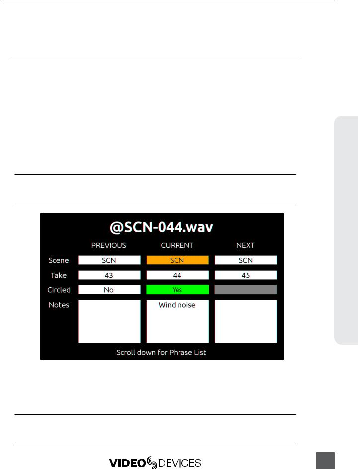
Metadata Screen
The Metadata screen gives you quick access to certain metadata for the previous, current, and next WAV recordings, letting you change the data in an instant.
The metadata you can edit includes:
Scene |
Use any alphanumeric value to name the scene. |
Take |
Use numeric values to name the take. |
Circled |
Options include: Yes | No |
Notes |
Type any brief notes maually or select from a pre-defined, customizable list of 20 most commonly used phrases. |
To access the Metadata screen, do one of the following:
•Press AUDIO + MENU.
•From an attached keyboard, press Ctrl+M.
If accessing the Metadata screen while recording, focus will be on the Scene field for the current take, so that field will be highlighted. If accessing the Metadata screen while in standby (stopped) mode, the Scene field for the next take will have the focus and appear highlighted.
To navigate the Metadata screen, do any of the following:
•Turn the Control knob to scroll vertically.
•Press the REW or FF buttons to move horizontally.
•From an attached keyboard, use the Arrow keys to navigate vertically or horizontally.
•Press the Control knob to make a selection.
Scrolling down and beyond the Notes field will display a customizable, predefined phrase list, letting you make quick notes with the most common wording. Scroll up to exit the list and return to the Metadata screen.
Menu & Navigation
11

Navigation & Menu
PIX 270i User Guide and Technical Information
Phrase List
The phrase list is a feature that lets you predefine a list of up to twenty most commonly used phrases, which can be added to WAV files as part of the Notes metadata. This list, once defined, can be used via the Metadata screen or the Take Details screen.
To define the phrase list:
1. Press the MENU button.
2. Select File Storage > Phrase List Manager. The Phrase List appears. 3. Select Add New Phrase.
4. Enter the text for that phrase.
Take Details Screen
While detailed file information is available via the FILES button, the Metadata screen also provides quick access to viewing take details for the previous, current, or next WAV recordings.
To access the Take Details View from the Metadata screen:
1. Use the Control knob to scroll up to the column header row: PREVIOUS CURRENT NEXT 2. Press the REW or FF buttons to move horizontally to select the previous, current or next take. 3. Push in the Control knob to display the details for the chosen take.
LCD
From the Main View, press LCD to toggle the On-Screen Display (OSD) on or off, press and hold LCD for two seconds to turn off the LCD, press again to turn on. From all other views, press LCD to return to the Main View. The LCD Control Panel provides adjustments to the LCD backlight, image brightness, image contrast, image chroma, and button backlight. To access the LCD Control Panel, press LCD + Control Knob. The parameter with the orange slider bar is the selected parameter. To toggle through the parameters press the Control Knob. To adjust the setting, turn the Control Knob. Press LCD again to exit back to the Main View.
12
v. 2.10 Features and specifications are subject to change. Visit www.sounddevices.com for the latest documentation.

PIX 270i User Guide and Technical Information
Inputs and Outputs
Video Inputs
The PIX 270i accepts video input signals over HDMI, HD-SDI, and single link 3G-SDI Level A and B.
The PIX 270i does not accept analog video signals. See the Specifications section for a complete list of supported frame rates.
HDMI
The PIX 270i accepts HDMI version 1.4a video and audio. Supported video resolutions and rates are listed in the Specifications section. The PIX 270i HDMI input accepts up to 10-bit, 4:4:4 video, up to 8 channels of embedded audio. The PIX 270i also accepts Sony’s proprietary timecode over HDMI. In Video Mode, the digital audio embedded in the HDMI stream (32 kHz – 192 kHz) is always re-sampled to 48 kHz. In Audio Mode it is re-sampled to the sample rate determined by the
[Timecode/Sync - Sync Ref - Audio Only].
720p30/29.97, 720p25, and 720p24/23.976 are not supported on the HDMI input or the HDMI output.
HDCP copy protection prevents direct digital-to-digital copying of copyrighted material. Protected DVDs, Blu-Rays, and streaming content with HDCP encryption is not valid content and will be ignored by the PIX 270i.
SDI
The SDI input on the PIX 270i accepts video with embedded audio (up to 16 channels) and embedded SMPTE timecode. This connection accepts digital video up to 12-bit, with up to 4:4:4 color sampling. Unlike the HDMI interface, which auto-negotiates rates between devices, what comes out of a camera’s SDI output is received by the PIX 270i with no auto-negotiation or sample rate conversion.
The PIX 270i supports 3G-SDI single link, but not dual-link HD-SDI.
Timecode over SDI is not available when recording in standard definition
Video Outputs
Both HDMI and SDI outputs are active simultaneously. This allows for conversion from SDI to HDMI and HDMI to SDI.
The output video signal source is the signal present at the currently selected video input (Setup Menu option [Video - Video Input]), except during video playback. The resolution and frame rate of the output stream is determined by the Setup Menu option [Video - File Resolution/Rate] setting, except during video playback. The SDI Output is capable of sending HD (4:2:2 10-bit) or 3G (4:4:4 12-bit), this is set in [Video - SDI Output Type].Video playback signal is sent to the HDMI and SDI Outputs.
Inputs & Outputs
13

PIX 270i User Guide and Technical Information
Standard Definition video is always output using HD Mode because 3G does not support Standard Definition.
The output video stream contains up to 16 tracks of embedded audio for SDI and 8 tracks for HDMI. Timecode and record start and stop flags are included on the SDI output.
Timecode overlay can be added to the HDMI and/or SDI output signal in
[Video - Video Output OSD]. The timecode overlay is displayed in various colors to indicate the current transport state of the PIX 270i: White = Stopped, Red = Record, Green = Playback.
Audio Inputs
Outputs & Inputs
14
The PIX 270i can record up to 64 tracks from a variety of audio input sources in both Video and Audio modes:
Input Type |
Count |
Connector(s) |
Gain |
Details |
|
|
|
1-8: DB-25 (CH 1-8 LINE IN) |
Off, -25 |
Balanced, Line-level. Channels 1-2 on DB-25 |
|
Analog |
8 |
connector are summed with respective XLR con- |
|||
1-2: XLR (LINE IN 1/2) |
to 20 dB |
||||
|
|
nectors. |
|||
|
|
|
|
||
|
|
|
|
|
|
AES Digital |
8 |
1-8: DB-25 (CH 1-8 AES IN/OUT) |
Off, -25 |
Selectable between AES or HDMI with Setup |
|
to 50 dB |
Menu option [Audio - HDMI/AES Select] |
||||
HDMI Digital |
8 |
1-8: HDMI Input |
Off, -25 |
Selectable between AES or HDMI with Setup |
|
to 20 dB |
Menu option [Audio - HDMI/AES Select] |
||||
|
|
|
|||
SDI Digital |
16 |
1-16: SDI Input |
Off, -25 |
|
|
to 20 dB |
|
||||
|
|
|
|
||
Dante |
64 |
1-64: Ethernet |
Off, -25 |
See Dante Audio Inputs for full details |
|
to 20 dB |
|||||
|
|
|
|
||
MADI |
64 |
1-64: Optical SC (MADI IN) |
Off, -25 |
See MADI Audio Inputs for full details |
|
1-64: BNC (MADI IN) |
to 50 dB |
||||
|
|
|
|||
|
|
|
|
|
Maximum amount of recording tracks is affected by sample rate. (See “Recording”, page 25)
Analog Audio Inputs
The PIX 270i has eight, high-performance, line-level analog audio inputs.
XLR (1-2)
The XLR balanced inputs accept line-level signals. These inputs are shared with Channels 1 and 2 of DB-25 Analog Audio Input connector. Channels 1 and 2 of this connector are summed with channels 1 and 2 of the DB-25 connector, respectively.
DB-25 (1-8)
Eight analog, line-level inputs are provided on the DB-25 Analog Audio Input connector. This connector is wired in the Tascam fashion (See “Connector Pin Assignments”, page 82). Channels 1 and 2 of this connector are summed with channels 1 and 2 XLR Analog Audio Inputs, respectively.
Digital Audio Inputs
The PIX 270i accepts digital audio from HDMI, SDI, AES/EBU, MADI, and Dante inputs. All digital inputs are sample rate converted. This helps ensure synchronization of digital audio from multiple sources. In Video Mode, audio is sampled at 48kHz. In Audio Mode, the sample rate is determined by the [Audio - Audio Mode Sample Rate] when [Timecode/Sync - Sync Ref - Audio Only] is set
to Internal. Otherwise, the Audio Mode sample rate is determined by the selected synchronization reference.
v. 2.10 Features and specifications are subject to change. Visit www.sounddevices.com for the latest documentation.
PIX 270i User Guide and Technical Information
AES3
The PIX 270i accepts AES3 (AES/EBU) digital signals with sampling rates from 32 kHz up to 192 kHz and bit depths up to 24-bits. In Video mode, AES3 inputs are sample rate converted to 48 kHz. In Audio Mode, the sample rate conversion is determined by Setup Menu option
[Timecode/Sync - Sync RefAudio Only]. see Audio Mode
All AES3 input signals must be clocked to the same rate.
MADI (AES10)
The PIX 270i accepts 64 channels of digital audio with sampling rates from 32 kHz up to 96 kHz and bit depths up to 24-bits. MADI Inputs 1 to 64 are derived from the MADI Input BNC connector and the MADI Input SC (optical) connector on the rear panel. The MADI connector used is configured with Setup Menu option [Audio - MADI Input]. When this option is set to Auto-Detect, signal for each channel will be derived from whichever MADI Input connector has signal. If signal is present on the same channel in both MADI Input connectors, the signal from the SC (optical) connector will be used.
HDMI / SDI Embedded Audio
The PIX 270i accepts 8 channels of embedded digital audio on the HDMI Video Input or 16 channels of digital audio on the SDI input.
Dante Audio Inputs
Dante delivers an easy-to-setup, self-configuring, plug-and-play digital audio network that uses standard Internet Protocols over 100Mb and/or Gigabit Ethernet. Dante reliably distributes multichannel digital audio with sub-millisecond latency and sample-accurate record and playback synchronization over CAT 5 cabling. Up to 64 Dante audio channels can be selected in any combination from any Dante audio device on the same Dante network. Should they be necessary, sample rate converters are automatically activated for all Dante audio inputs.
An input Source can be set to an available Dante channel from the PIX 270i or from the Dante Controller application (Available from Audinate’s website: http://www.audinate.com/) running on a computer attached to the network. To select a Dante source from the PIX 270i, follow the instructions in the Choosing Audio Sources section of this guide (See “Choosing Audio Sources”, page 16).
To route Dante channels with the Dante Controller application:
1. Open the Dante Controller application.
2. Select the Routing tab. This table displays Dante devices with available outputs (“Dante Transmitters”) horizontally, and Dante devices with available inputs (“Dante Receivers”) vertically. PIX 270i units will be represented by their PIX names per Setup Menu option
[Network - This PIX’s Name].
3. Click the plus symbol (+) where the column of the desired Dante transmitting device intersects with the row of the PIX 270i you wish to set input sources on. This expands the table to display a matrix of the transmitting device’s outputs to the PIX 270i’s inputs.
4. Click the slots in the matrix where you wish to route or un-route audio channels. A green circle with a check mark will appear in slots that are routed.
Inputs & Outputs
15

Outputs & Inputs
PIX 270i User Guide and Technical Information
Dante Redundancy
When [Network - Dante Redundancy Mode] is set to On, the PIX 270i’s Primary and Secondary Ethernet ports both transmit Dante Audio data over separate networks. This provides a fail safe of the Dante system if one of the networks should fail.
In Dante Redundancy Mode, two separate networks must be run and they CANNOT be connected to one another. Connect any computer running Dante Controller to the PIX 270i’s PRI Ethernet network.
See http://www.audinate.com/ for further information on the Dante protocol.
Sample Rate Converters
All digital inputs have Sample Rate Converters. These help ensure synchronization of digital audio from multiple sources.
Choosing Audio Sources
Audio Input Source is selected in the Audio Screen in the Source column. To setup an input:
1. Press AUDIO to access the Audio Screen. If the Source column is not visible, press AUDIO again to reveal it.
2. Rotate the Control Knob to select the desired track.
3. Press the Control Knob to focus the highlighter on the selected track’s parameters. The high- lighter will become orange and focus on a single column in the track.
4. Rotate the Control Knob to highlight the Source column.
16
v. 2.10 Features and specifications are subject to change. Visit www.sounddevices.com for the latest documentation.

PIX 270i User Guide and Technical Information
5. Press the Control Knob to open the Audio Source options window. Select the general type of input to be used from Off, Line In, HDMI/AES In, MADI In, or SDI In and press the Control
Knob again to open up all options for that input type.
6. Press the Control Knob to make a selection and exit the Audio Input Source options window.
Dante sources must be connected in order to select them as audio input sources.
For quick general audio source configurations use [Audio - Audio Input Quick Setup]. (See “Setup Menu Options”, page 71)
Input Gain Control
Audio Input Gain is set in the Audio Screen in the Gain column. To adjust the gain of an audio track:
1. Press AUDIO to access the Audio Screen. If the Gain column is not visible, press AUDIO again to reveal it.
2. Rotate the Control Knob to select the desired track.
3. Press the Control Knob to focus the highlighter on the selected track’s parameters. The high- lighter will become orange and focus on a single column in the track.
4. Rotate the Control Knob to highlight the Gain column.
5. Press the Control Knob to edit the gain value. Turn the Control Knob to adjust the gain in 1 dB increments. Gain is adjusted in real time. The available gain range depends on the audio input source. (See “Audio Inputs”, page 14)
6. Once the desired gain value is set, press the Control Knob to exit the gain window.
Input Gain can be linked in [Audio - Input Gain Linking]. When linked, adjust any channel’s gain value to adjust the gain of all channels. Gain offsets from channel to channel are maintained. If this is not desired, unlink the gain and set all gain values to the same value, then re-link input gain.
Input Delay Control
Audio Input Delay is set in the Audio Screen in the Delay column. Delay is adjustable from 0 to 400 mS. To adjust the delay of an audio track:
1. Press AUDIO to access the Audio Screen. If the Delay column is not visible, press AUDIO again to reveal it.
2. Rotate the Control Knob to select the desired track.
3. Press the Control Knob to focus the highlighter on the selected track’s parameters. The high- lighter will become orange and focus on a single column in the track.
4. Rotate the Control Knob to highlight the Delay column.
5. Press the Control Knob to edit the delay value. Turn the Control Knob to adjust the delay in 1 mS increments.
6. Once the desired delay value is set, press the Control Knob to exit the delay window.
Input Delay can be linked in [Audio - Input Delay Linking]. When linked, adjust any channel’s delay value to adjust the delay of all channels. Delay offsets from channel to channel are maintained. If this is not desired, unlink the delay and set all delay values to the same value then re-link input delay.
Inputs & Outputs
17

PIX 270i User Guide and Technical Information
Outputs & Inputs
Audio Outputs
Analog Audio Outputs
The eight analog outputs of the PIX 270i are active-balanced, line-level outputs (+18dBu max). At factory default, the source of the Analog Line Outputs 1-8 is tracks 1 to 8, respectively. Any of the available 64 Tracks can be sent to the Line Outputs. Line Output routing is set in [Audio - Line Output].
Digital Audio Outputs (HDMI/AES)
AES and HDMI Outputs are active at all times but these two outputs share the same source. At factory default, the source of the HDMI/AES Outputs 1-8 is tracks 1 to 8, respectively. Any of the availabe 64 Tracks can be sent to the HDMI/AES Outputs. HDMI/AES Output routing is set in
[Audio - HDMI/AES Output].
SDI Audio Outputs
The SDI video output embeds up to 16 channels of digital audio. At factory default, the source of the SDI Audio Outputs 1-16 is tracks 1 to 16, respectively. Any of the available 64 Tracks can be sent to the SDI Output. SDI Output routing is set in: [Audio - SDI Output].
Dante Audio Outputs
Tracks 1-64 are permanently routed to Dante Outputs 1-64 respectively. Up to four PIX 270i units can be daisy-chained using their built-in internal Ethernet switches. If using five or more PIX 270i units, Sound Devices recommends using an external Ethernet Switch in a star configuration.
MADI Audio Output
Both the SC Optical and BNC MADI outputs provide 64 channels of digital audio. At factory default, the source of the MADI Audio Outputs 1-64 is tracks 1 to 64, respectively. Any of the available 64 Tracks can be sent to the MADI Output. MADI Output routing is set in: [Audio - MADI Output].
Headphone Output
The PIX 270i is capable of driving headphones to extremely high sound pressure levels. Hearing experts advise against exposure to high sound pressure levels for extended periods.
The PIX 270i’s headphone output is a flexible tool for monitoring audio. The headphone level is adjusted using the Headphone Volume Knob.
To quickly select a headphone source, press and hold AUDIO then turn the Control Knob. The Headphone Source can also be selected in the Setup Menu option [Audio - HP Source]. To solo a track, enter the Audio Screen, highlight the track, then press AUDIO + LCD. The solo headphone source will be indicated on the top-left of the Audio Screen (HP: Solo8 for example). To stop solo of a track, highlight the soloed track, then press AUDIO + LCD.
Warning Bells are sent to the headphone monitor to alert the user of various states such as transport changes, and errors such as No Media Connected or No Input Signal Detected. The loudness of these warning bells is adjustable from Off, -60 to -12 dBFS in [System - HP Warning Bell Level]. At factory default, the warning bells are set to -40 dBFS.
18
v. 2.10 Features and specifications are subject to change. Visit www.sounddevices.com for the latest documentation.

PIX 270i User Guide and Technical Information
Ethernet
The PRI and SEC Ethernet ports on the rear panel of the PIX 270i are used for a variety of PIX 270i functions/features:
•Dante (64-Channel Audio I/O over network) (See “Dante Audio Inputs”, page 15)
•Network Grouping (See “Network Grouping”, page 47)
•File Transfer (Samba) (See “Transferring Files”, page 66)
•Web Browser Control (See “Web Interface - PIXNET”, page 50)
Up to four PIX 270i units can be daisy-chained using their built-in Ethernet switches. If using five or more PIX 270i units, Sound Devices recommends using an external Ethernet Switch in a star configuration.
The PIX 270i can either be allocated an IP address from a DHCP server (recommended) or over Linklocal networking. Link-local networking is a protocol which automatically allocates a 169.254.x.x IP address in the absence of any DHCP server. If a DHCP server is available, the PIX 270i will automatically use it if [Network - Auto IP Settings] is set to On.
Alternatively, the IP address can be configured manually. When Setup Menu option [Network - Auto IP Settings] is set to Off, Setup Menu options [Network - IP Address],
[Network - Subnet Mask], and [Network - Gateway] are enabled. When these settings are improperly set, the PIX 270i may be unreachable in the network or may cause conflicts resulting in other devices in the network being unreachable. Consult with an IT technician to determine the appropriate settings when connecting to a large network.
The PIX 270i uses on-board Auto-MDIX (crossover detection) to allow for direct connection to a computer or to a network.
Dante uses a separate IP Address which is configured automatically when connected to other Dante devices. This IP Address is displayed when connected to a computer running Dante Controller, a free-of-charge application available from Audinate. See the following link for details about Dante Controller’s capabilities.
http://www.audinate.com/
In Dante Redundancy Mode, two separate IP Addresses are used by Dante. (See “Dante Redundancy”, page 16)
Ethernet
19

PIX 270i User Guide and Technical Information
Video Monitoring Features
The PIX 270i includes various monitoring features to assist with exposure and focus. These functions only affect signal on the LCD display and will never affect the recorded video or the video output signal.
Exposure Assist
Features Monitoring Video
20


 +
+ 


LCD FILES
Exposure assist features mark areas of the video image based on the exposure level. With overor under-exposed areas of the image clearly marked, adjustments can be made on the camera to ensure that the signal reaching the recorder has a proper exposure. Exposure Assist is enabled by pressing LCD + FILES. When Exposure Assist is enabled, “EXP” is displayed on the OSD in yellow text.
When exposure assist is enabled, False Color or Zebra stripes will be overlaid on the LCD monitor signal. The Setup Menu option [LCD Monitor - Exposure Assist] determines which mode will activate when exposure assist is toggled on.
The following image is a luminance ramp signal displayed on a PIX 270i with no exposure assist enabled. Screen shots in the following sections show the effect of the various Exposure Assist features on this test signal.
False Color
False Color exposure assist mode replaces pixels with a specific color relative to the luminance level. The two types of False Color (selectable from Setup Menu option [LCD Monitor - Exposure Assist]) are 12-step and 4-step.
v. 2.10 Features and specifications are subject to change. Visit www.sounddevices.com for the latest documentation.

PIX 270i User Guide and Technical Information
12-step False Color mode divides the monitor signal into 12 luminance ranges and assigns a color to each.
4-step False Color mode divides the monitor signal into 4 ranges and assigns a color to all but one range (this range is displayed without chroma). The table below illustrates the colors as they relate to luminance levels (IRE).
12-step
100-108 Red
95-99 Orange
85-94 Yellow
79-84 Light Yellow
59-78 Light Grey
53-58 Pink
49-52 Medium Grey
43-48 Green
23-42 Dark Grey
13-22 Light Blue
3-12 Blue
0-2 White
4-step
101+ Red
99-100 Orange
3-98 N/A
0-2 Blue
Zebras
Zebra stripe exposure assist mode overlays diagonal stripes over areas that are in a defined luminance range (Zebra 1) or above a defined luminance threshold (Zebra 2). The range for Zebra 1 is 5% above and below the IRE value of Setup Menu option [LCD Monitor - Zebra 1 Level]. The range for Zebra 2 is everything above the IRE value of Setup Menu option [LCD Monitor - Zebra 2 Threshold]. The options for Zebra display (selectable from Setup Menu option [LCD Monitor - Exposure Assist]) are Zebra 1, Zebra 2, or both Zebra 1 and Zebra 2 simultaneously.
Video Monitoring Features
21

PIX 270i User Guide and Technical Information
Features Monitoring Video
Zebra 2 |
Zebra 1 |
70 IRE (+/- 5%) |
85 IRE |
Focus Assist


 +
+ 


LCD MENU
Focus Assist features mark sharp edges in the video image to assist in focusing on the desired subject. Focus assist is enabled pressing LCD + MENU. The word “FOCUS” is displayed in yellow text on the OSD when Focus Assist is enabled. There are two available Focus Assist modes: Peaking and Edge Enhance.
Peaking
Peaking finds sharp edges in a video (based on luminance) and replaces pixels in those areas to highlight the edges.
The Setup Menu option [LCD Monitor - Peaking Sensitivity] sets sensitivity level of the Peaking filter. A setting of High will be more sensitive and highlight more edges.
The Setup Menu option [LCD Monitor - Peaking Background Contrast] is used to adjust the area of the video image that is not highlighted while Peaking is enabled.
The color of the Peaking marks can be set with the Setup Menu option
[LCD Monitor - Peaking Color].
The following image comparison demonstrates the effect of Peaking on an image with a shallow depth-of-field and a short focal length (top) and a longer focal length (bottom).
22
v. 2.10 Features and specifications are subject to change. Visit www.sounddevices.com for the latest documentation.

PIX 270i User Guide and Technical Information
Edge Enhance
The Edge Enhance filter uses an algorithm which enhances the variation of the luminance of all edges present in the video image. The following image comparison demonstrates the effect of Edge Enhance on an image with a shallow depth-of-field and a short focal length (top) and a longer focal length (bottom).
Video Monitoring Features
23

PIX 270i User Guide and Technical Information
Zoom


 +
+ 


LCD AUDIO
Features Monitoring Video
24
The Zoom function enlarges the video image to a 1:1 pixel ratio. To toggle Zoom on and off, press LCD + AUDIO. When Zoom is enabled, “ZOOM” is displayed on the OSD in yellow text and all other OSD elements are hidden. When zoomed, turning the Control Knob moves vertically and Rewind and Fast Forward buttons move left and right, respectively.
Flip Display
Some mounting situations require the PIX 270i (or camera) to be upside-down. The LCD output can be vertically inverted to facilitate upside-down operation with the Setup Menu option [LCD Monitor - Verical Flip Display]. The Setup Menu option
[LCD Monitor - Horizontal Flip Display] option reverses the LCD output signal hoizontally (mirror image).
Vertical and Horizontal flipping affect the video image on the LCD screen only. Recorded content and HDMI/SDI outputs are not affected.
v. 2.10 Features and specifications are subject to change. Visit www.sounddevices.com for the latest documentation.
Loading...