


 Loading...
664
Portable Production Mixer and Recorder User Guide and Technical Information firmware rev. 2.02
UDMA
E7556 State Rd. 23 and 33, Reedsburg, WI, USA |
www.sounddevices.com |
+1 (608) 524-0625 • Toll-Free: (800) 505-0625 • fax: +1 (608) 524-0655 |
support@sounddevices.com |
664 User Guide and Technical Information
Table of Contents
Panel Descriptions |
|
|
1 |
Front Panel..................................... |
. 1 |
Right Panel..................................... |
. 3 |
Left Panel. . . . . . . . . . . . . . . . . . . . . . . . . . . . . . . . . . . . . . |
. 3 |
Rear Panel.. . . . . . . . . . . . . . . . . . . . . . . . . . . . . . . . . . . . . |
. 5 |
Screen Overview |
|
|
6 |
Main Screen. . . . . . . . . . . . . . . . . . . . . . . . . . . . . . . . . . . . |
. 6 |
LCD Daylight Mode .. . . . . . . . . . . . . . . . . . . . . . . . . . . . . |
. 7 |
Meter Views.................................... |
. 6 |
|
|
Input Setup and Control |
|
|
8 |
Input Settings Screen.. . . . . . . . . . . . . . . . . . . . . . . . . . . . |
. 8 |
Pan Control.. . . . . . . . . . . . . . . . . . . . . . . . . . . . . . . . . . . |
. 11 |
Phantom Power .. . . . . . . . . . . . . . . . . . . . . . . . . . . . . . . |
. 10 |
Input Linking.. . . . . . . . . . . . . . . . . . . . . . . . . . . . . . . . . . |
. 11 |
Gain/Trim and Fader Relationship .. . . . . . . . . . . . . . . . |
. 10 |
Digital Inputs. . . . . . . . . . . . . . . . . . . . . . . . . . . . . . . . . . |
. 12 |
High-Pass Filter.. . . . . . . . . . . . . . . . . . . . . . . . . . . . . . . . |
. 11 |
12 Channel Mode.. . . . . . . . . . . . . . . . . . . . . . . . . . . . . . |
. 13 |
Limiters |
|
|
15 |
Metering |
|
|
16 |
Meter Ballistics .. . . . . . . . . . . . . . . . . . . . . . . . . . . . . . . . |
. 16 |
Headphone Peak LED. . . . . . . . . . . . . . . . . . . . . . . . . . . |
. 17 |
Input Activity LED.. . . . . . . . . . . . . . . . . . . . . . . . . . . . . . |
. 17 |
|
|
Headphone Monitoring |
|
|
18 |
Headphone Gain. . . . . . . . . . . . . . . . . . . . . . . . . . . . . . . |
. 18 |
PFL (Channel Solo Monitor). . . . . . . . . . . . . . . . . . . . . . |
. 20 |
Headphone Source Selection .. . . . . . . . . . . . . . . . . . . . |
. 18 |
RTN and COMM Monitoring. . . . . . . . . . . . . . . . . . . . . |
. 20 |
Headphone Tones.. . . . . . . . . . . . . . . . . . . . . . . . . . . . . |
. 19 |
|
|
Output Setup and Control |
|
22 |
|
Master and Aux Outputs.. . . . . . . . . . . . . . . . . . . . . . . . |
. 22 |
AES Digital Outputs.. . . . . . . . . . . . . . . . . . . . . . . . . . . . |
. 23 |
Master and Aux Bus Level.. . . . . . . . . . . . . . . . . . . . . . . |
. 23 |
|
|
COM Setup |
|
|
24 |
COM Send Program.. . . . . . . . . . . . . . . . . . . . . . . . . . . . |
. 24 |
Com Program Auto-Mute.. . . . . . . . . . . . . . . . . . . . . . . |
. 24 |
Slate/Com Mic & Tone Oscillator |
25 |
||
Slate Microphone.. . . . . . . . . . . . . . . . . . . . . . . . . . . . . . |
. 25 |
Alternate Slate/Com Switch. . . . . . . . . . . . . . . . . . . . . . |
. 25 |
Tone Oscillator................................. |
. 25 |
|
|
Digital Audio Recorder |
|
|
26 |
Table of Contents
i

664 User Guide and Technical Information
Contents of Table
ii
Transport Control.. . . . . . . . . . . . . . . . . . . . . . . . . . . . . . |
. 26 |
Pre-Roll. . . . . . . . . . . . . . . . . . . . . . . . . . . . . . . . . . . . . . . |
. 34 |
Recording Tracks.. . . . . . . . . . . . . . . . . . . . . . . . . . . . . . . |
. 26 |
Synchronization .. . . . . . . . . . . . . . . . . . . . . . . . . . . . . . . |
. 34 |
Sampling Rate.. . . . . . . . . . . . . . . . . . . . . . . . . . . . . . . . . |
. 28 |
File Management.. . . . . . . . . . . . . . . . . . . . . . . . . . . . . . |
. 34 |
Bit Depth . . . . . . . . . . . . . . . . . . . . . . . . . . . . . . . . . . . . . |
. 29 |
Take Management.. . . . . . . . . . . . . . . . . . . . . . . . . . . . . |
. 40 |
Recording Media............................... |
. 29 |
Playback.. . . . . . . . . . . . . . . . . . . . . . . . . . . . . . . . . . . . . . |
. 42 |
Time Code.. . . . . . . . . . . . . . . . . . . . . . . . . . . . . . . . . . . . |
. 30 |
|
|
Using a USB Keyboard |
|
|
44 |
Mixer Linking |
|
|
45 |
Linking the 664 With Another 664 or 552 Mixer.. . . . |
. 45 |
Linking to Other Mixers. . . . . . . . . . . . . . . . . . . . . . . . . |
. 45 |
Powering |
|
|
47 |
External Powering .. . . . . . . . . . . . . . . . . . . . . . . . . . . . . |
. 47 |
Voltage Metering.. . . . . . . . . . . . . . . . . . . . . . . . . . . . . . |
. 47 |
Internal Battery Powering.. . . . . . . . . . . . . . . . . . . . . . . |
. 47 |
Power Consumption. . . . . . . . . . . . . . . . . . . . . . . . . . . . |
. 48 |
Storing and Recalling Settings |
49 |
||
Time and Date Settings |
|
|
50 |
Time Zone and Daylight Savings. . . . . . . . . . . . . . . . . . |
. 50 |
Time and Date Format.. . . . . . . . . . . . . . . . . . . . . . . . . . |
. 50 |
Setup Menu |
|
|
51 |
Inputs.. . . . . . . . . . . . . . . . . . . . . . . . . . . . . . . . . . . . . . . . |
. 51 |
Timecode/Sync.. . . . . . . . . . . . . . . . . . . . . . . . . . . . . . . . |
. 54 |
Outputs .. . . . . . . . . . . . . . . . . . . . . . . . . . . . . . . . . . . . . . |
. 51 |
File Storage.. . . . . . . . . . . . . . . . . . . . . . . . . . . . . . . . . . . |
. 54 |
Limiters. . . . . . . . . . . . . . . . . . . . . . . . . . . . . . . . . . . . . . . |
. 52 |
System .. . . . . . . . . . . . . . . . . . . . . . . . . . . . . . . . . . . . . . . |
. 55 |
Recorder. . . . . . . . . . . . . . . . . . . . . . . . . . . . . . . . . . . . . . |
. 52 |
Quick Setup.. . . . . . . . . . . . . . . . . . . . . . . . . . . . . . . . . . . |
. 57 |
Comms/Returns.. . . . . . . . . . . . . . . . . . . . . . . . . . . . . . . . |
. 53 |
|
|
Front Panel Button Shortcuts |
58 |
||
Connector Pin Assignments |
|
60 |
|
Routing Diagram |
|
|
62 |
Specifications |
|
|
63 |
Analog Inputs . . . . . . . . . . . . . . . . . . . . . . . . . . . . . . . . . |
. 63 |
Timecode and Sync.. . . . . . . . . . . . . . . . . . . . . . . . . . . . . |
. 65 |
Digital Inputs. . . . . . . . . . . . . . . . . . . . . . . . . . . . . . . . . . |
. 63 |
Power.. . . . . . . . . . . . . . . . . . . . . . . . . . . . . . . . . . . . . . . . |
. 65 |
Analog Outputs.. .. .. .. .. .. .. .. .. .. .. .. .. .. .. .. .. .. .. .. .. .. .. .. .. .. .. .. .. .. .. .. .. 64 |
Environmental .. . . . . . . . . . . . . . . . . . . . . . . . . . . . . . . . |
. 65 |
|
Digital Outputs/Recorder .. . . . . . . . . . . . . . . . . . . . . . . |
. 64 |
Dimensions and Weight .. . . . . . . . . . . . . . . . . . . . . . . . |
. 65 |
Accessories |
|
|
66 |
v. 2.02 Features and specifications are subject to change. Visit www.sounddevices.com for the latest documentation.

|
664 User Guide and Technical Information |
|
Wave Agent |
67 |
|
Declaration of Conformity |
68 |
|
Warranty and Technical Support |
69 |
|
Table of Contents
iii

664 User Guide and Technical Information
Copyright Notice and Release
Contents of Table
iv
All rights reserved. No part of this publication may be reproduced, stored in a retrieval system, or transmitted in any form or by any means, electronic, mechanical, photocopying, recording, or otherwise, without the expressed written permission of SOUND DEVICES, LLC. SOUND DEVICES is not responsible for any use of this information.
Microsoft Windows is a registered trademark of Microsoft Corporation. Macintosh is a registered trademark of Apple Computer. Other product and company names mentioned herein may be the trademarks of their respective owners.
The sound waves logo is a registered trademark of Sound Devices, LLC.
Limitation of Liability
LIMITATION ON SOUND DEVICES’ LIABILITY. SOUND DEVICES, LLC SHALL NOT BE LIABLE TO THE PURCHASER OF THIS PRODUCT OR THIRD PARTIES FOR DAMAGES, LOSSES, COSTS, OR EXPENSES INCURRED BY PURCHASER OR THIRD PARTIES AS A RESULT OF: ACCIDENT, MISUSE, OR ABUSE OF THIS PRODUCT OR UNAUTHORIZED MODIFICATIONS, REPAIRS, OR ALTERATIONS TO THIS PRODUCT, OR FAILURE TO STRICTLY COMPLY WITH SOUND DEVICES, LLC’S OPERATING AND INSTALLATION INSTRUCTIONS. TO THE FULLEST EXTENT PERMITTED BY LAW, SOUND DEVICES SHALL HAVE NO LIABILITY TO THE END USER OR ANY OTHER PERSON FOR COSTS, EXPENSES, DIRECT DAMAGES, INCIDENTAL DAMAGES, PUNITIVE DAMAGES, SPECIAL DAMAGES, CONSEQUENTIAL DAMAGES OR OTHER DAMAGES OF ANY KIND OR NATURE WHATSOEVER ARISING OUT OF OR RELATING TO THE PRODUCTS, THESE TERMS AND CONDITIONS OR THE PARTIES’ RELATIONSHIP, INCLUDING, WITHOUT LIMITATION, DAMAGES RESULTING FROM OR RELATED TO THE DELETION OR OTHER LOSS OF AUDIO OR VIDEO RECORDINGS OR DATA, REDUCED OR DIMINISHED AUDIO OR VIDEO QUALITY OR OTHER SIMILAR AUDIO OR VIDEO DEFECTS ARISING FROM, RELATED TO OR OTHERWISE ATTRIBUTABLE TO THE PRODUCTS OR THE END USER’S USE OR OPERATION THEREOF, REGARDLESS OF WHETHER SUCH DAMAGES ARE CLAIMED UNDER CONTRACT, TORT OR ANY OTHER THEORY. “CONSEQUENTIAL DAMAGES” FOR WHICH SOUND DEVICES SHALL NOT BE LIABLE SHALL INCLUDE, WITHOUT LIMITATION, LOST PROFITS, PENALTIES, DELAY DAMAGES, LIQUIDATED DAMAGES AND OTHER DAMAGES AND LIABILITIES WHICH END USER SHALL BE OBLIGATED TO PAY OR WHICH END USER OR ANY OTHER PARTY MAY INCUR RE-
LATED TO OR ARISING OUT OF ITS CONTRACTS WITH ITS CUSTOMERS OR OTHER THIRD PARTIES. NOTWITHSTANDING AND WITHOUT LIMITING THE FOREGOING, IN NO EVENT SHALL SOUND DEVICES BE LIABLE FOR ANY AMOUNT OF DAMAGES IN EXCESS OF AMOUNTS PAID BY THE END USER FOR THE PRODUCTS AS TO WHICH ANY LIABILITY HAS BEEN DETERMINED TO EXIST. SOUND DEVICES AND END USER EXPRESSLY AGREE THAT THE PRICE FOR THE PRODUCTS WAS DETERMINED IN CONSIDERATION OF THE LIMITATION ON LIABILITY AND DAMAGES SET FORTH HEREIN AND SUCH LIMITATION HAS BEEN SPECIFICALLY BARGAINED FOR AND CONSTITUTES AN AGREED ALLOCATION OF RISK WHICH SHALL SURVIVE THE DETERMINATION OF ANY COURT OF COMPETENT JURISDICTION THAT ANY REMEDY HEREIN FAILS OF ITS ESSENTIAL PURPOSE.
v. 2.02 Features and specifications are subject to change. Visit www.sounddevices.com for the latest documentation.
664 User Guide and Technical Information
Panel Descriptions
Front Panel
4 5 6
1
2 3
|
7 |
8 |
9 |
10 |
|
|
|
|
|
|
11 |
|
|
|
|
|
12 |
|
|
|
|
|
13 |
|
|
|
|
|
14 |
19 |
18 |
|
17 |
16 |
15 |
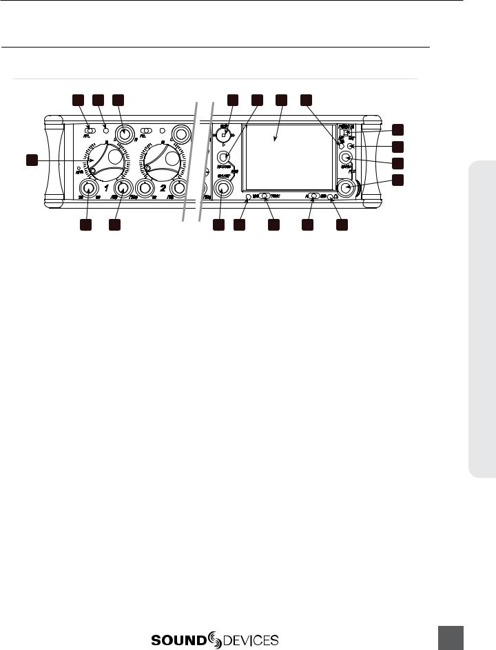
1)Input Fader
Primary control for adjusting the level of an input during operation. Ranges from off to +15 dB. Nominal setting is in the middle (0 dB).
2)Gain (Trim)
Coarse input gain control. Sets the initial input sensitivity level so that the Input Fader can be used for fine gain adjustments. Range is from +22 dB to +72 dB.
See Input Setup and Control.
3)Highpass Filter Control
5)Input LED
Indicates input signal activity. Illuminates in various colors and intensities to show signal level and activity. Green = signal presence (pre-fader), yellow = limiter activity (preand post-fade), red = signal overload/clipping (preand post-fade), flashing yellow = input PFL.
6)Input Pan
Controls the Left/Right balance of the input signal to the Stereo Master Bus.
7)Transport Control
Adjusts corner (-3 dB) frequency of highpass filter. Full counter-clockwise position (detented) deactivates the High-Pass Filter. Range is 80-240 Hz, 12 dB/oct to 6 dB/oct. See Input Setup and Control.
4)PFL / Input Select Switch
Slide left: Pre-Fade Listen. Sends the input’s pre-fade signal to HP monitor mono mix. The 664 supports simultaneous PFL of multiple inputs. Does not affect Master Output signal. Slide the switch left to activate, and again to deactivate. For momentary action, hold the switch left for one second or longer. The Input LED flashes yellow when an input’s PFL is active. Slide right: Input Settings. Enters the Input Settings Screen where basic input setup and input-to-output bus routing is performed. See Input Setup and Control.
Controls the Integrated Digital Recorder. Slide up to Record, press in to Pause/ Stop, slide down to Play, slide left to Rewind, slide right to Fast Forward. See Digital Audio Recorder.
8)Meters Button
Displays the Main Screen which includes metering, filename, time code and other important information. Cycles between available Meter Views when pressed from Main Screen (see Meter Views). Returns to Main Screen from any other Screen.
9)LCD
Displays contextual operating information and user interface.
Panel Descriptions
1

664 User Guide and Technical Information
Descriptions Panel
2
10)Internal Time code LED
When the 664 is powered down and time code Mode is Freerun or 24-Hour Run, the Internal Time code LED will flash blue to indicate that time code is being maintained. The 664 will hold accurate time code for 2 hours after being powered down.
11)Power Switch
Three-position slide switch, selects between AA battery power or external DC sources, middle position is off.
12)Power LED
Illuminates green to indicate the 664 is powered on.
13)Menu Button
Displays the Setup Menu.
14)Headphone Encoder
Main and Input Settings Screen: Turn to adjust headphone gain. In Main Screen: Press to select headphone monitor source. In Menus: Turn to navigate; Press to make selection. In Input Settings Screen press to select input source. Headphone gain and preset selection functions can be reversed: see Headphone Monitoring
15)Headphone Clipping LED
Illuminates red to indicate headphone output is approaching clipping level.
16)RTN Switch
Slide Left to activate RTN A, slide Right to activate RTN B. To access secondary function Press and hold Select Encoder then slide left for COM RTN and right for RTN C. Primary and Secondary functions of the RTN toggle switch can be selected in the Setup Menu.
17)Slate / Tone Switch
Slide left to activate the Slate Microphone, slide again to deactivate. For momentary action hold for one second or longer. Slide right to activate the Tone Oscillator. Tone will latch if held for one second or longer; slide again to deactivate. Secondary function: press and hold Select Encoder then slide Mic switch to activate COM. Primary and Secondary functions can be switched in the Setup Menu.
18)Slate Mic LED
Illuminates green when Slate Mic or COM is active.
19)Select Encoder
Multi-function encoder. Selects Tracks and RTN’s on the Main Screen. On the Main Screen, press the Select Encoder and the Meters button to arm/disarm record tracks. With L, R, X1, X2, or any RTN selected, press then turn to adjust level. Vertical Scroll in matrix windows. Turn to adjust digital trim level in Input Settings Window. Turn to scroll cursor and press to insert a space character during text entry. Acts as shift button to access secondary functions.
v. 2.02 Features and specifications are subject to change. Visit www.sounddevices.com for the latest documentation.

664 User Guide and Technical Information
Left Panel
1
4 |
3 |
2 |
1)XLR-3F Analog Inputs 1-6
Active-balanced analog microphoneor line-level input for inputs 1-6 on XLR-3F connector. Input type is set within the Input Settings Screen. Inputs 1 and 6 can also accept AES3 or AES42 (Mode 1) signal. Pin-1 ground, pin-2 (+), pin-3 (-).
2)Headphone Output
1/4-inch and 3.5 mm TRS stereo headphone connectors. Can drive headphones from 8 to 1000 ohm impedances to very high levels. Tip = left, ring = right, sleeve = ground.
3)Slate Mic Input
TA3 input for connecting external slate microphone. Select between internal or external slate mic (with or without 12V phantom) from the Setup Menu section COMMS/RETURNS. Pin-1 ground, pin-2 (+), pin-3 (-).
4)TA3 Direct Outputs 1-6 / Inputs 7-12
Balanced direct outputs on TA3 connectors. Direct output signal is preor post-fader and level is selected between Line, -10, and Mic levels in the Setup Menu section OUTPUTS. Tone signal appears at the direct outputs. These connections can optionally be selected as analog line inputs 7-12. Pin 1 = Ground; pin 2 = Hot (+); pin 3 = Cold (-) float pin 3 to unbalance.
Right Panel
1 |
|
|
|
|
2 |
3 |
4 |
5 |
6 |
7 |
|
||||
|
|
|
|
|
|
|
|
|
|
|
|
|
|
|
|
|
|
|
|
|
|
|
|
|
|
|
|
|
|
|
|
|
|
|
|
|
|
|
|
|
|
|
|
|
|
|
|
|
|
|
|
|
|
|
|
|
|
|
|
|
|
|
|
|
|
|
|
|
|
|
|
|
|
|
|
|
|
|
|
|
|
|
|
|
|
|
|
|
|
|
|
|
|
|
|
8
13 |
12 |
11 |
10 |
9 |
Panel Descriptions
3

664 User Guide and Technical Information
Descriptions Panel
4
1)USB B Connector
Factory use and keyboard connection (with adapter).
2)Time code I/O
Time code input and output on 5-pin LEMO® connector.
3)10-pin A and C
Each connection includes a pair of transformer-isolated Outputs and a stereo unbalanced Return input. Analog Output levels are selected between Line, -10, and Mic levels in Setup Menu section OUTPUTS. 10-pin A outputs can be set
to AES Outputs 5,6 and 7,8 in the Setup Menu section OUTPUTS.
4)Tape Output
Unbalanced stereo, tape level output on TA3 (Pin 1 = Ground, pin 2 = Left, pin 3 = Right) and 3.5 mm (Sleeve = Ground, Tip = Left, Ring = Right) connector.
5)X1 and X2 Outputs
Line, -10, or Mic level selected in the Setup Menu section OUTPUTS. Pin 1 = Ground, pin 2 = Hot (+), pin 3 = Cold (-) float pin 3 to unbalance.
6)TA3 Master Outputs
Line, -10, or Mic level selected in the Setup Menu section OUTPUTS. Pin 1 = Ground, pin 2 = Hot (+), pin 3 = Cold (-) float pin 3 to unbalance.
7)Link I/O
Used to link additional Sound Devices 664, 552, 302, 442, or MixPre mixers.
8)Battery Compartment
Holds five AA (LR6) batteries for backup powering. NiMH rechargeable cells advised.
9)DC Input
Accepts DC voltages from 10–18 V for powering. Pin 1 = Negative (–), pin 4 = Positive (+). Ext DC is fully isolated (floating) from the rest of the circuitry.
10)XLR-3M Master Outputs
Transformer-balanced analog outputs on standard 3-pin XLR-3M connectors. Pin
1= Ground; pin 2 = Hot (+); pin 3 = Cold (-). Unbalance by grounding pin 3 to pin
1.Can be set to send AES3 digital signals (1,2 and 3,4 on L and R respectively) in Setup Menu section OUTPUTS.
11)RTN B Input
Unbalanced stereo 3.5 mm female connector for Return B audio input. Sleeve = Ground, Tip = Left, Ring = Right.
12)CompactFlash Slot
Accepts approved CompactFlash cards with the label-side toward the rear of the
664.Compatible with Type I and Type
II cards. High-speed UDMA cards are recommended for higher track count recording.
13)SD Card Slot
Accepts SD/SDHC/SDXC cards with the notched corner oriented toward the top of the 664. High speed class 10 cards are recommended. Insert until it clicks securely in the slot. The card should glide smoothly into the slot. Press to eject.
Visit www.sounddevices.com/approved for an up-to-date list of tested and approved cards.
v. 2.02 Features and specifications are subject to change. Visit www.sounddevices.com for the latest documentation.
664 User Guide and Technical Information
Rear Panel
4 |
3 |
12
1)BNC Word Clock Input
Accepts word clock rates between 32 kHz and 48.048 kHz for synchronizing the internal recorder to external digital audio devices.
2)BNC Word Clock Output
Provides word clock signal to synchronize external digital audio devices to the 664.
3)TA3 COM Send
Unbalanced, stereo, line-level output. Program assigned to COM output from Setup Menu.
4)TA3 COM Return
Line-level input for return feed from onset communications sources.
Panel Descriptions
5

664 User Guide and Technical Information
Screen Overview
Main Screen
Overview Screen
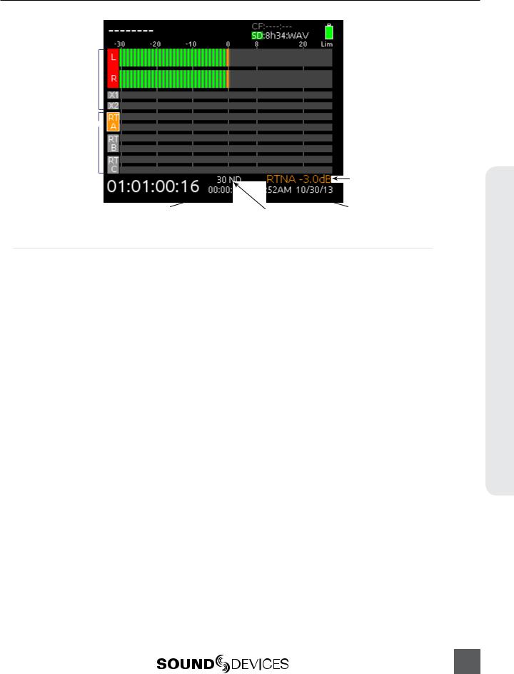
The Main Screen displays important information at-a-glance. The Main Screen can be accessed quickly from any other screen by pressing the Meters button. Display of the sample rate information and time code frame rate information can be “swapped” by holding the Meters button and Sliding the RTN Switch to the left.
Current take |
Media information |
||||||
|
|
|
|
|
|
|
|
|
|
|
|
|
|
|
|
|
|
|
|
|
|
|
|
 Power source level
Bus tracks
Armed track 
Input tracks
Unarmed track 
Monitor (Headphone) information
SMPTE Timecode 
Absolute |
|
Sample rate information |
|
RTN levels |
recording time |
|
Meter Views
Various combinations of input, track, and return meters are available for viewing on the Main Screen. These various signal sources are grouped into preset Meter Views. Pressing the Meters button on the Main Screen will cycle through up to 3 different Meter Views. Access Setup Menu option SYSTEM > Meter Views to define the selectable Meter Views.
In the Meter View titles, RTNs refers to 2-channel meters for RTN A, RTN B, and RTN C. (wide) indicates that the preceding source will be displayed with a taller, more visible meter. The LR(wide),X1X2,RTNs Meter View demonstrates this:
6
v. 2.02 Features and specifications are subject to change. Visit www.sounddevices.com for the latest documentation.
664 User Guide and Technical Information
Bus tracks
RTN during gain adjustment
Return inputs
Return gain (during adjustment)
SMPTE Timecode 
Absolute |
|
Timecode frame rate |
|
Time and date |
recording time |
|
LCD Daylight Mode
When engaged, LCD Daylight Mode changes the color scheme of the user interface to be more easily viewable in environments with bright ambient light or direct sunlight. LCD Daylight Mode can be engaged from the Setup Menu option SYSTEM > LCD Daylight Mode or toggled quickly by pressing and holding the Headphone Encoder then pressing the Select Encoder.
Screen Overview
7
664 User Guide and Technical Information
Input Setup and Control
Control & Setup Input
The 664 has six, full-featured audio inputs on XLR-3F connectors and six direct outputs on TA3 connectors. The direct outputs can optionally be used as line inputs (see 12 Channel Mode). Each analog input has a wide gain range to accommodate nearly all signal types, from microphones to line-level sources. Inputs can be used as either balanced or unbalanced connections. To unbalance, tie pin-3 to pin-1 of the XLR connector of the cable. There is no change in gain between unbalanced and balanced connections into the 664.
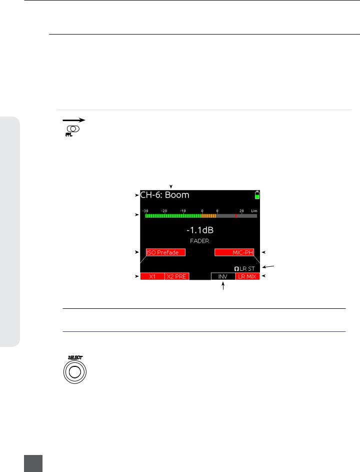
Input Settings Screen
Each input’s settings are accessed through its Input Settings Screen. To access the Input Settings screen for an input, slide the Input Selector Switch to the right. The LCD will display information pertaining to the selected input and provide access to.
input/Track Name
Input/Track Number |
|
|
|
|
|
|
|
|
|
|
|
|
|
|
|
|
|
|
|
|
|
|
|
|
|
|
|
|
|
|
|
|
|
|
|
|
|
|
|
|
|
|||
|
|
|
|
|
|
|
|
|
|
|
|
|||
|
|
|
|
|
|
|
|
|
|
|
|
|
|
|
2) Input Meter |
|
|
|
|
|
|
|
|
|
|
|
|
||
|
|
|
|
|
|
|
|
|
|
|
|
|||
|
|
|
|
|
|
|
|
|
|
|
|
|
|
|
Current Fader Gain |
|
|
|
|
|
|
|
|
|
|
|
|
||
|
|
|
|
|
|
|
|
|
|
|
|
|||
|
|
|
|
|
|
|
|
|
|
|
|
|
|
|
1) ISO Track Status |
|
|
|
|
|
|
|
|
|
|
|
|
3) |
Input Selection |
|
|
|
|
|
|
|
|
|
|
|
|
|||
|
|
|
|
|
|
|
|
|
|
|
|
|||
|
|
|
|
|
|
|
|
|
|
|
|
|||
|
|
|
|
|
|
|
|
|
|
|
|
|
Headphone Source / Level |
|
|
|
|
|
|
|
|
|
|
|
|
|
|
||
4) Aux Bus Assignment |
|
|
|
|
|
|
|
|
|
|
5) |
LR Bus Assignment |
||
|
|
|
|
|
|
|
|
|
|
|
|
|||
|
|
|
|
|
|
|
|
|
|
|||||
|
|
|
|
|
|
|
|
|
|
|
|
|
|
|
6) Input Polarity
The method for accessing the Input Settings screen is altered when in 12 Channel Mode. See 12 Channel Mode.
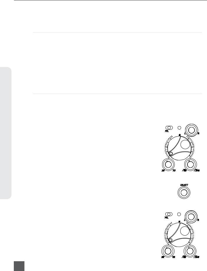
1) ISO Track Status
Displays the status of the Input’s dedicated Iso Track on the recorder. Each input is permanently routed to its Iso track. To select whether an input is routed preor post-fade, press the Select Encoder, turn it to make a selection, and press it again to confirm the selection.
The background color of the Iso Track Status box indicates the status of the Input’s Iso Track. A blue background indicates that the Iso Track is not active and will not be recorded. A red background indicates the Iso Track is armed for recording.
8
v. 2.02 Features and specifications are subject to change. Visit www.sounddevices.com for the latest documentation.

664 User Guide and Technical Information
2) Input Meter
Displays the Input’s signal level and limiting activity. The level displayed is the level to the Iso Track and will be preor post-fade depending on the Iso Track Status. Meter ballistics can be set globally from VU or Peak+VU in Setup Menu item SYSTEM > Meter Ballistics.
3) Input Selection
Displays the available input types. To change the input type, press the Headphone Encoder, turn it to make a selection, and press it again to confirm the selection.
Input Type |
Description |
|
Off |
Input off. |
|
|
|
|
MIC |
Use with dynamic microphones or other mic-level signals. |
|
|
|
|
MIC-PH |
Use with phantom-powered condenser microphones only. Provides 48V or 12V phantom power. |
|
|
see Phantom Power |
|
LINE |
For use with any line-level source. |
|
|
|
|
LINE-PH |
For use with phantom-powered condenser microphones only. Provides 48V or 12V phantom |
|
|
power, but at a line-level gain range. Useful for recording extremely loud sounds. |
|
AES42 (Mode 1) |
Digital input with power activated for digital microphones. Inputs 1 and 6 (channels 1, 2, 5, and |
|
|
6) only. |
|
AES3 |
Digital input. Inputs 1 and 6 (channels 1, 2, 5, and 6) only. |
|
|
|
|
AES42 and AES3 input source option only appears in input 2 when selected as a source for input 1, and only appears in input 5 when selected as a source for input 6. Input 1 and input 6 XLR-3F connectors are used for digital inputs.
4) Aux Bus Assignment
Displays the status of the Input’s assignment to the X1 and X2 Output Buses. Inputs 2 through 5 can only be routed to X1 and X2 post-fade, while Inputs 1 and 6 can be routed to X1 and X2 preor postfade. Slide the Slate / Tone Switch left for the X1 Track and right for the X2 Track to cycle through the available options.
5) LR Bus Assignment
Displays the status of the Input’s assignment to the main Left and Right Output Buses. Inputs routed to the Left and Right Output Bus are always post-fader and post-pan. To add or remove the Input from the Left and Right Output Bus, slide the RTN Switch to the right.
6) Input Polarity (Inputs 2, 4, and 6)
Input Setup & Control
9
664 User Guide and Technical Information
Control & Setup Input
Polarity reversal is used to compensate for incorrectly wired balanced cables, to prevent signal cancellation when a source is dual-miked from opposite directions, or to reverse left/right with microphones in a mid-side (MS) configuration.
Phantom Power
Phantom powering is a fixed DC voltage of either 12 or 48 Volts. This voltage is resistively applied to pin 2 and pin 3 of an input’s XLR-3F connector, relative to pin 1. In this configuration, there is no voltage difference between signal pins 2 and pin 3.
The phantom voltage is selectable between 12 and 48 Volts from the Setup Menu item
INPUTS > Phantom Voltage. The selected voltage level applies to all inputs with phantom power enabled. The factory default phantom power voltage is 48 V.
Phantom power can be activated for each input. To enable phantom power, enter the input’s channel screen, press the Headphone Controller, highlight either MIC-PH or LINE-PH, press Headphone Controller again to make the selection.
Gain/Trim and Fader Relationship
The gain of an input is adjusted by two controls, Input Trim and Input Fader. This two-stage architecture is identical to the topology of large mixing consoles and provides a great deal of control. Input Trim is often thought of as a course gain control and the Input Fader as the fine gain control.
Input Trim (Analog)
The 664’s analog input sensitivity is set with the pop-up Trim control knob. With the Input Fader set to unity gain (0 dB or 12 o’clock), make the appropriate adjustments using the Trim control. Once the coarse gain is set to the desired level, press the Trim control to hide it from the 664’s mixing surface. Analog trim level is adjustable from +22 to +72 dB of gain.
Input Trim (Digital)
The coarse level of a digital input is set by rotating the Select Encoder in the Input Settings Screen of an input with a digital source. The digital trim level is displayed on the LCD when adjusted. The digital trim level is adjustable from -20 to +50 dB.
Input Fader
The Input Fader is the primary control used while mixing and it affects the level of the Input signal routed to all post-fade destinations. Use the
Input Fader to make fine gain adjustments. The fader can be attenuated from off (full counter-clockwise position) to +15 dB above the set Trim level (full clockwise position). To optimize gain structure for the best performance, operate input faders at or near the 0 dB (unity gain) position.
10
v. 2.02 Features and specifications are subject to change. Visit www.sounddevices.com for the latest documentation.

664 User Guide and Technical Information
High-Pass Filter
Each input channel has an adjustable high-pass filter controlled by the High-Pass Filter control. High-pass (or low-cut/low roll-off) filters are useful for removing excess low frequency energy from audio signals.
Wind noise is a common unwanted low frequency signal that can be reduced with the use of a high-pass filter. For most audio applications, engaging the high-pass filter is beneficial, because audio information below 100 Hz is rarely used, especially for speech reproduction.
The 664’s high-pass filter circuit features an adjustable corner (-3 dB) frequency over a range from 80 to 240 Hz. Below 80 Hz, the filter’s slope is 12 dB/octave. At higher corner frequency settings, the slope is 6 dB/oc-
tave. The purpose for this compound slope is to give additional roll-off at
the 80 Hz setting to reduce wind noise and low frequency rumble. The higher settings can be used to counteract the proximity effect of directional microphones where a more gentle slope is desired.
The 664’s high-pass filter circuit is unique because of its placement before any electronic amplification. Most mixers’ high-pass filter circuits are placed after the microphone preamplifier, such that all of the low-frequency signals get amplified. By virtue of the 664’s circuit cutting the low-frequency signals before amplification, higher headroom is achieved in the presence of signals with significant low-frequency energy.
When possible, attempt to equalize at the sound source with microphone selection, placement, windscreens, and onboard microphone filtering. Many microphones have on-board high pass filters. Use the high-pass filters on the 664 in conjunction with the microphone’s filter to increase the filter’s slope.
The filter can be removed from the circuit completely by rotating the high-pass filter control to the full counter-clockwise (detented) position. The high-pass filter potentiometer can be adjusted easily and then recessed to hide it from the mixing surface.
Pan Control
The pop-up Pan Control routes inputs to the left (L) and right (R) channels of the stereo Master Bus. The pan pot has a detent in the center posi- tion. After setting the pan, the pan control can be recessed to hide it from the mixing surface during normal operation.
Input Linking
Input pairs 1-2, 3-4, and 5-6 can be linked as stereo pairs. When a pair of inputs is linked:
• Each channels’ Trim Control and High-Pass Filter Control work as normal, controlling coarse gain and high-pass filtering for their respective inputs.
• The odd channel’s Input Fader controls the post-fade level of both inputs.
Input Setup & Control
11

664 User Guide and Technical Information
Control & Setup Input
• The odd channel’s Pan Control controls the balance of the stereo signal to the Master Bus. When linked MS, the odd channel’s Pan Control functions as a left/right balance control for the matrixed MS signal.
• The even channel’s Fader Control and Pan Control are disabled. • The limiters of both inputs are linked.
• The background label of both inputs is connected on the Main Screen.
Linked 
Unlinked 
M/S Matrixing
When input pairs are linked MS, the odd channel is used for the Mid signal and the even channel is used for the Side signal. To produce a stereo signal from an M/S configuration, the signal from both microphones must be processed.
Mid-side (MS) matrixing is a method for processing audio signal from a cardioid microphone and a bidirectional microphone into a stereo signal. The cardioid microphone is the “mid” signal and
connects to the odd Input, and the bidirectional microphone is the “side” signal and connects to even Input. The cardioid microphone is pointed at the sound source, and the bidirectional microphone
is oriented sideways (positioned with its capsule as near as possible to the cardioid microphone’s capsule). The following diagram shows the relative polar patterns of microphones in an M/S configuration.
Mid Signal
Side Signal
Digital Inputs
The 664 accepts AES3 (AES/EBU) balanced, AES42 (Mode 1) balanced, and AES3id unbalanced digital signals on the Input 1 and Input 6 XLR-3F connectors. The 664 auto-detects between AES3 and AES3id digital signals and adjust accordingly. Digital input gain is controlled from the front panel faders.
Never attach unbalanced connections to an input set for AES42. This can result in damage to the hardware.
To use a digital input, slide the Input 1 or Input 6 Input Selector Switch to the right to enter the Input Settings Screen. Press the Headphone Encoder to display the list of available input sources. Turn
the Headphone Encoder to select AES3 or AES42, and press the Headphone Encoder to confirm the selection.
12
v. 2.02 Features and specifications are subject to change. Visit www.sounddevices.com for the latest documentation.
664 User Guide and Technical Information
Each connector carries two channels of digital audio. Alternate channels of digital audio sent to Input 1 or Input 6 are available on adjacent inputs, according to the following table.
|
AES Input Channel: |
Available to 664 Input: |
|
XLR-3F |
Input 1, Left Channel |
Input 1 |
|
|
|
|
|
XLR-3F |
Input 1, Right Channel |
Input 2 (Available when Input 1 source is set to AES) |
|
|
|
|
|
XLR-3F |
Input 6, Left Channel |
Input 5 (Available when Input 6 source is set to AES) |
|
|
|
|
|
XLR-3F |
Input 6, Right Channel |
Input 6 |
|
|
|
|
|
The 664’s digital inputs are sample rate converted to the internal recorder’s sample rate. To sync the sample rate of the 664’s internal recorder to external digital audio devices, see Sampling Rate.
Things to consider when using AES digital inputs:
• When using an unbalanced AES3 (SPDIF) input, the other available digital input should not be used with an AES42 microphone.
• Signal from digital inputs is not available on direct outputs.
12 Channel Mode
Direct outputs 1 to 6 can be used as line inputs in 12 Channel Mode. When Setup Menu option INPUTS > Input Mode is set to 12 Channel, direct outputs 1 to 6 are changed to line inputs 7 to 12, respectively. Each input is routed to its own ISO track and can be recorded. Each 7-12 input can be switched to be a direct output for its respective 1-6 input.
When switching to 12 Channel Mode, Meter Views are not changed automatically, so inputs 7-12 may not be visible on any Meter View (See Meter Views). To automatically switch Meter Views while switching between 6 Channel and 12 Channel Mode, it is recommended to save custom Setup Files with the desired Input Mode and Meter Views. See Storing and Recalling Settings
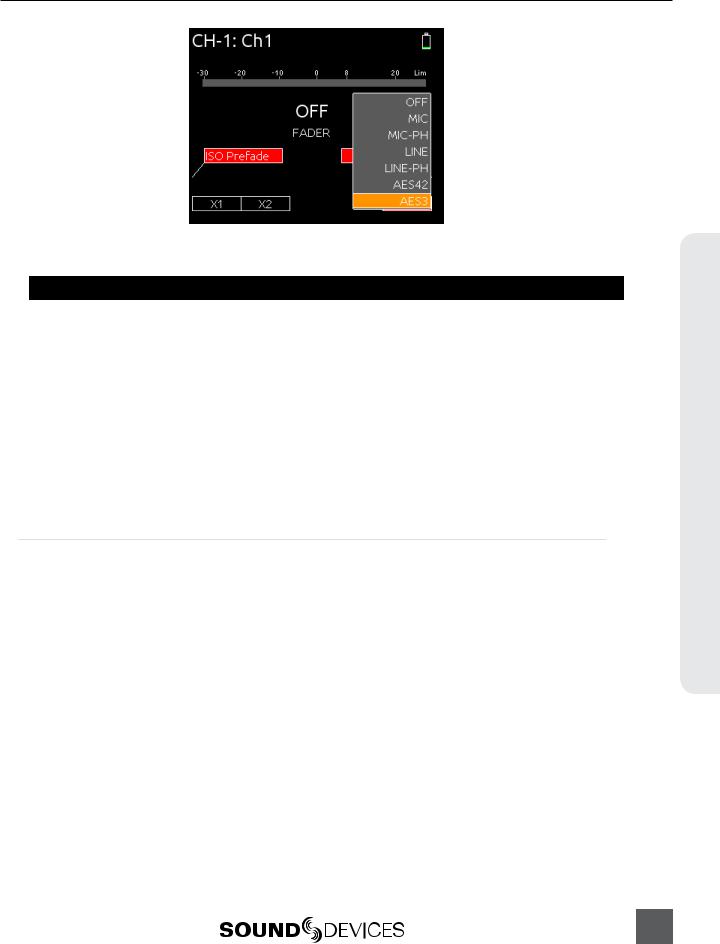
The function of the Input Selector switches is altered in 12 Channel Mode: Slide the switch to the right to PFL and access the Input Settings screen for inputs 7-12, and slide the Input Selector switch left to PFL and access the Input Settings screen for inputs 1-6. The Input Settings screen for inputs 7-12 is slightly different than the Input Settings screens for inputs 1-6. HPF, Trim, and Fader values are adjusted using the Select Encoder:
Input Setup & Control
13
664 User Guide and Technical Information
Control & Setup Input
White box indicates selected parameter. Rotate Select Encoder to adjust value. Press Select Encoder to move to next parameter (HPF, Trim, Fader).
Press Headphone Encoder
 to set to Line Input, Direct
Output, or Off.
Press the Select Encoder to cycle the white highlighter box between HPF, Trim, and Fader. Rotate the Select Encoder to adjust the value of the highlighted parameter (Acceleration is applied to Trim and Fader adjustments to enable fast adjustments). To change an input back to a direct output for its respective 1-6 input, press the Headphone Encoder and select the DIR.OUT option.
The Input Settings screen for inputs 7-12 can be access without engaging PFL for that input by holding the Select Encoder down while sliding the Input Selector switch.
PFL of multiple inputs simultaneously is disabled in 12 Channel Mode.
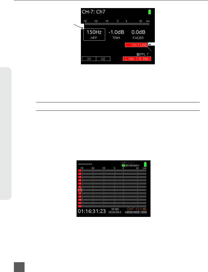
Input 7-12 faders can also be adjusted from the Main Screen:
1. Press the Meters button until a Meter View which displays the desired input is visible. 2. Turn the Select Encoder to highlight the input to be adjusted.
3. Press the Select Encoder to access fader adjustment mode for the selected input. The input’s fader value (in dB) will appear in the lower right corner of the LCD.
4. Turn the Select Encoder to adjust the gain. Fader adjustment mode will exit automatically after 3 seconds.
Channel being adjusted
 Fader value (during adjustment)
14
v. 2.02 Features and specifications are subject to change. Visit www.sounddevices.com for the latest documentation.
664 User Guide and Technical Information
Limiters
Limiters prevent clipping by attenuating signals that surpass a set threshold. The amount of attenuation is defined by the “ratio” of the limiter and expressed as two numbers. All 664 limiters use a 20:1 compression ratio. This means that signal that exceeds the threshold by 20 dB will exit the limiting stage at only 1 dB above the threshold.
The time it takes for limiting to begin once signal has exceeded the threshold is referred to as the “attack time” and the time it takes for limiting to cease once signal has fallen back below the threshold is referred to as “release time”. Signals that exceed the threshold faster than the limiter’s attack time can still cause clipping. The 664 limiters have a 1 ms attack time and a 500 ms release time.
The limiters are globally activated when the Setup Menu item LIMITERS > Limiters is set to On. This activates both the input limiters (Inputs 1 through 6) and all output limiters. Sound Devices recommends using the limiters at all times. Limiters are present on both mic and line-level inputs as well as the Master L,R tracks and the X1,X2 tracks. The 664 input limiters have a threshold of +16 dBu (4 dB below clipping), while the limiters for the L, R, X1, and X2 tracks are adjustable from the Setup Menu item OUTPUTS > L,R Limiter Thresh and OUTPUTS > X1,X2 Limiter Thresh.
In normal operation, with a properly set gain structure, the threshold of the Input Limiter is rarely reached. Without Input Limiters, high signal conditions can overload a channel and cause distortion. The Input limiter is working when the respective input’s Input Activity LED illuminates yellow. If the Activity LED is regularly in the yellow, reduce the amount of gain applied to the channel by turning down the Trim control. See Input Activity LED for additional information.
When Inputs are linked as a stereo pair, the Input Limiters are also linked and perform the same gain reduction equally to both inputs.
The Output Limiters prevent the L,R and X1,X2 signal from exceeding the user-set limiter threshold. Setup Menu options LIMITERS > L,R Limiter Thresh and LIMITERS > X1,X2 Limiter Thresh allow limiter thresholds to be set in 1 dB increments from +4 dBu to +20 dBu.
Limiters
15

664 User Guide and Technical Information
Metering
Input, Track, and RTN levels are displayed in the various Meter Views on the Main Screen (see Meter Views). Each segment of the meter represents 1 dB. A larger red square under the 20 dBU marker indicates clipping on the track. A large yellow square indicates limiting activity on the track.
 Input clipping
 Limiter active
Meters can be displayed with segments or solid lines (Setup Menu option
SYSTEM > Meter Display Style). Track Names can also be displayed on top of meters in various styles (Setup Menu option SYSTEM > Track Names in Meters). The following screen shots demonstrate solid meters and the available Track Name display styles.
Metering
16
|
Meter Appearance |
Track Name Display Style |
|
|
|
|
|
Off |
|
|
|
|
||
|
|
|
|
|
|
|
|
Left |
|
|
|
|
|
|
|
|
|
Left (w/ramp) |
|
|
|
|
|
|
|
|
|
Right |
|
|
|
|
|
|
|
|
|
|
|
Meter Ballistics
Audio meter “ballistics” is the manner in which a visual meter responds to audio signal levels. The ballistics of all 664 meters is set globally from Setup Menu option SYSTEM > Meter Ballistics.
VU
VU (volume units) meter ballistics correspond closely to how the human ear perceives loudness. This provides a good visual indication of how loud a signal will be. In VU mode, the attack and decay of the meter signal is 300 mS. VU meters provide good visual indication of how loud a signal will be, but provide poor information of actual signal peaks.
Peak + VU
The 664 can simultaneously display VU and Peak level information. In this mode the perceived loudness (VU) is displayed as a standard bar, and the Peak signal as a single, independent segment above the VU.
Peak Only
Peak-reading ballistics (PPM) correspond to actual signal peaks, but don’t necessarily correspond to perceived signal loudness. Peak meters have an instantaneous attack and a slow decay to allow visual monitoring of peak activity. Peak metering is useful when interconnecting to audio inputs on digital equipment. In the digital realm, signal overload can cause immediate distortion.
v. 2.02 Features and specifications are subject to change. Visit www.sounddevices.com for the latest documentation.
664 User Guide and Technical Information
Peak Hold
When Peak Metering is enabled (Peak Only or Peak + VU), peak hold displays the last highest peak value on the meter as a separate, individual meter segment. By default this meter segment will remain visible for 1 second. This time can be adjusted from Setup Menu option
SYSTEM > Meter Peak Hold Time to 1, 2, 3, 4, or 5 seconds. The Infinity option will display the last highest peak indefinitely until a higher peak is reached. The Off option will disable peak hold.
Input Activity LED
Each Input has its own Input Activity LED located just above the Input Fader. The LED illuminates in various colors and intensities to represent the signal level appearing at its respective input. Green = pre-fade signal activity, yellow = preand post-fader limiter activity, red = preand post-fader signal overload (peaking). Reduce the trim level control if the LEDs continuously illuminate yellow or red. The Input Activity LED will flash yellow when the Input PFL is latched. see PFL.
Headphone Peak LED
The Headphone Peak LED is located just left of the Headphone Encoder.
This LED will illuminate red to indicate clipping in the headphone amplifier.
Monitoring without a visual indication of headphone clipping can mislead the sound mixer into thinking that the output or return feeds are distorted.
Metering
17
664 User Guide and Technical Information
Headphone Monitoring
Headphone Gain
Monitoring Headphone
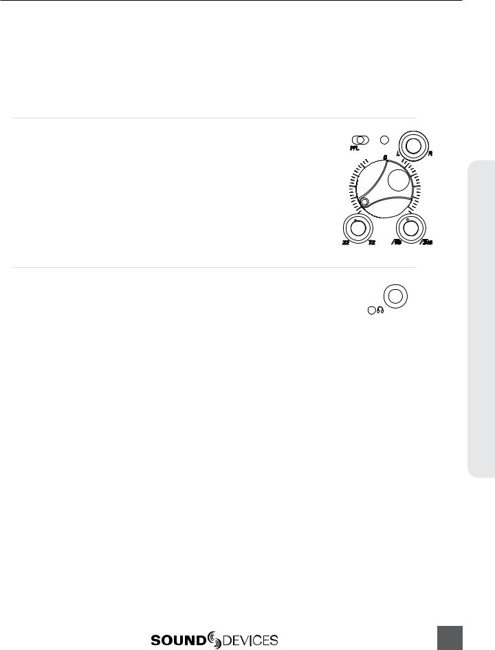
By default, headphone output level is controlled by turning the Headphone Encoder while viewing the Main Screen or Input Settings Screen. When adjusting the headphone gain, the gain value (in dB) is displayed in the lower right corner of the LCD (Near the Headphone Encoder). This space displays the currently selected headphone source when the headphone gain is not being adjusted.
Headphone gain during adjustment
 Headphone Encoder
The 664 can drive headphones to dangerously high volumes. Turn down the headphone gain before selecting a headphone source to prevent accidental signal extremes.
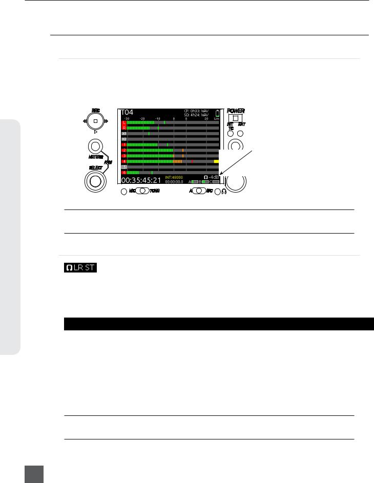
Headphone Source Selection
By default, to select the monitor source: Press the Headphone Encoder while viewing the Main Screen. This will display a list of available monitor sources. Turn the Headphone Encoder to highlight a source, and press the Headphone Encoder to select that source. The signal to the headphone outputs will immediately change to the selected program.
Monitor Source |
Description |
|
LR ST |
Master Bus in stereo. |
|
|
|
|
LR Mono |
Master Bus summed mono to both ears. |
|
|
|
|
L Mono |
Left channel of Master Bus sent to both ears. |
|
|
|
|
R Mono |
Right channel of Master Bus sent to both ears. |
|
|
|
|
LR MS ST |
Mid-Side Stereo - Master Bus decoded MS stereo to headphones, this is not to be used if the inputs |
|
|
are already linked as an MS pair. |
|
X1X2 |
Aux Bus in stereo. |
|
|
|
|
HP Preset |
HP Presets 1-10 are customizable monitor sources. See Headphone Presets |
|
|
|
|
The visibility of presets in the Headphone Source selection menu can be toggled individually from Setup Menu option SYSTEM > Headphone Preset List.
18
v. 2.02 Features and specifications are subject to change. Visit www.sounddevices.com for the latest documentation.
Loading...