


 Loading...
633
Portable Production Mixer and Recorder User Guide and Technical Information Firmware Version 1.02
Sound Devices, LLC
E7556 State Highway 23 and 33 • Reedsburg, WI • USA • 53959 +1 (608) 524-0625 • fax: +1 (608) 524-0655
Toll-Free: (800) 505-0625
www.sounddevices.com UDMA support@sounddevices.com

633 User Guide and Technical Information
Table of Contents
Panel Descriptions |
|
|
|
1 |
Front Panel. . . . . . . . . . . . . . . |
. |
. 1 |
Right (Output) Panel . . . . . . . . . . . . |
. 3 |
Left (Input) Panel. . . . . . . . . . . . . |
. |
3 |
Rear Panel . . . . . . . . . . . . . . . . |
. 4 |
Quick Start Guide |
|
|
|
5 |
Screen Overview |
|
|
|
10 |
Primary Screen Elements.. . . . . . . . . |
. |
10 |
Input Settings Screen. . . . . . . . . . . . |
11 |
Meter Views.. . . . . . . . . . . . . . . . . . . . . . . . . . . . . . . . . . . . . |
. . |
.10 |
L, R, 1-6 .. . . . . . . . . . . . . . . . . . . . . . . . . . . . . . . . . . . . . . . . . . |
. . 11 |
L, R, X1, X2, 1-6.. .. .. .. .. .. .. .. .. .. .. .. .. .. .. .. .. .. .. .. .. .. .. .. .. .. .. .. .. .. .. .. .. .. .. .. .. ..10 |
L, R, X1-X4, RTN.. . . . . . . . . . . . . . . . . . . . . . . . . . . . . . . . . . . |
. . 11 |
||
L, R, 1-3 .. . . . . . . . . . . . . . . . . . . . . . . . . . . . . . . . . . . . . . . . . |
. . . |
10 |
Routing Screens. . . . . . . . . . . . . . |
13 |
|
|
|
LCD Daylight Mode. . . . . . . . . . . . |
13 |
Inputs |
|
|
|
14 |
Input Types. . . . . . . . . . . . . . . |
. |
14 |
Phantom Power. . . . . . . . . . . . . . |
16 |
Input Routing. . . . . . . . . . . . . . |
. |
14 |
Digital Inputs. . . . . . . . . . . . . . . |
16 |
Pan Control.. . . . . . . . . . . . . . . |
|
15 |
High-pass Filter. . . . . . . . . . . . . . |
17 |
Trim and Fader Relationship. . . . . . . . |
. |
15 |
Polarity. . . . . . . . . . . . . . . . . |
. 17 |
Input/Trim (Analog). . . . . . . . . . . . . . . . . . . . . . . . . . . . . . . |
. . . |
15 |
Input Linking . . . . . . . . . . . . . . . |
18 |
Input Trim (Digital).. . . . . . . . . . . . . . . . . . . . . . . . . . . . . . . . |
. . . |
15 |
M/S Matrixing.. . . . . . . . . . . . . . . . . . . . . . . . . . . . . . . . . . . . |
. .18 |
Input Fader.. . . . . . . . . . . . . . . . . . . . . . . . . . . . . . . . . . . . . . |
. . . |
16 |
|
|
Limiters |
|
|
|
19 |
Limiter Knee. . . . . . . . . . . . . . . |
. 19 |
Linking Limiters. . . . . . . . . . . . . . |
19 |
|
Metering |
|
|
|
20 |
Meter Ballistics. . . . . . . . . . . . . . |
. 20 |
Input Activity LED. . . . . . . . . . . . . |
. 21 |
|
VU. . . . . . . . . . . . . . . . . . . . . . . . . . . . . . . . . . . . . . . . . . . . . . |
. . . |
20 |
Headphone Clipping LED. . . . . . . . . . |
21 |
Peak + VU.. . . . . . . . . . . . . . . . . . . . . . . . . . . . . . . . . . . . . . . |
. . . |
20 |
|
|
Peak Only.. . . . . . . . . . . . . . . . . . . . . . . . . . . . . . . . . . . . . . . |
. . . |
20 |
|
|
Peak Hold.. . . . . . . . . . . . . . . . . . . . . . . . . . . . . . . . . . . . . . . |
. . . |
21 |
|
|
Headphone Monitoring |
|
|
|
22 |
Headphone Gain. . . . . . . . . . . . . |
. 22 |
PFL (Input Solo). . . . . . . . . . . . . . |
24 |
|
Headphone Source Selection. . . . . . . . |
|
22 |
Headphone Bells. . . . . . . . . . . . . |
. 25 |
Headphone Encoder Mode.. . . . . . . . . . . . . . . . . . . . . . . . |
. . . |
23 |
PFL Toggle Mode.. . . . . . . . . . . . . . . . . . . . . . . . . . . . . . . . . . |
. .25 |
Custom Headphone Presets.. . . . . . . . . . . . . . . . . . . . . . . . |
. . . |
23 |
RTN Monitoring . . . . . . . . . . . . . . |
25 |
Favorite Headphone Source.. . . . . . . . . . . . . . . . . . . . . . . |
. . . |
24 |
|
|
Output Setup and Control |
|
|
|
26 |
Table of Contents
i

633 User Guide and Technical Information
Contents of Table
Master Outputs (XLR-3M). |
. . . . . . . . . . . . . . . . . . . 26 |
AES3 Digital Outputs (XLR-3M). . |
. . . . . . 27 |
AUX 1/2 Outputs (TA3). . . |
. . . . . . . . 26 |
Adjusting Output Levels. . . . . . . . |
. . 27 |
AUX 3/4 Outputs (TRS).. |
. . . . . . . . . . 26 |
|
|
Slate Mic and Tone Oscillator |
|
29 |
||
Slate Microphone. . . . . . . . . . . . |
. |
. 29 |
Routing Slate and Tone Signals . . . . . . . |
29 |
Tone Oscillator. . . . . . . . . . . . . |
. |
. 29 |
|
|
Recorder Setup and Control |
|
31 |
||
Transport Control (Recording and Playback). |
. |
. 31 |
Bit Depth.. . . . . . . . . . . . . . . . |
35 |
Recording Tracks . . . . . . . . . . . . |
. |
. 31 |
Recording Media . . . . . . . . . . . . . |
. 35 |
Track Arming .. . . . . . . . . . . . . . . . . . . . . . . . . . . . . . . . . |
. . . |
. . .31 |
Formatting Media .. . . . . . . . . . . . . . . . . . . . . . . . . . . . . . . . . |
. .35 |
Track-to-Media Routing.. . . . . . . . . . . . . . . . . . . . . . . . . . |
. . |
. . .32 |
Pre-Roll. . . . . . . . . . . . . . . . . |
. 36 |
Track Naming.. . . . . . . . . . . . . . . . . . . . . . . . . . . . . . . . . . |
. . |
. . .32 |
“F Mode” Sample Rates. . . . . . . . . . |
36 |
Digital Audio Format & File Format . . . . |
. |
. 34 |
48..048k and 48..048kF. . . . . . . . . . . . . . . . . . . . . . . . . . . . . |
. .36 |
WAV (Broadcast WAV) File Format.. . . . . . . . . . . . . . |
. . . |
. . .34 |
Fostex DV40.. . . . . . . . . . . . . . . . . . . . . . . . . . . . . . . . . . . . . . |
. .36 |
MP3 File Format.. . . . . . . . . . . . . . . . . . . . . . . . . . . . . . . . |
. . |
. . .34 |
47..952k and 47..952kF.. . . . . . . . . . . . . . . . . . . . . . . . . . . . . |
. .36 |
MP3 Bit Rate.. . . . . . . . . . . . . . . . . . . . . . . . . . . . . . . . . . . |
. . |
. . .34 |
Playback. . . . . . . . . . . . . . . . . |
37 |
Sample Rate. . . . . . . . . . . . . . |
. |
. 35 |
|
|
File Management |
|
|
|
38 |
File List . . |
. . . . . . |
. . . . . . . . |
. |
|
. 38 |
|
File Format |
. . . . . . |
. . . . . . . . . |
. |
39 |
||
File Structure. . . . |
. . . . . |
. . . . . . |
|
|
39 |
|
Folder Options. . |
. . . |
. . . . . . . . |
. |
|
. 40 |
|
Automatic File splitting . |
. . . . . . . . |
. |
. |
41 |
||
Metadata Fields. . |
. . |
. . . . . . . . . |
. |
41 |
||
Metadata in MP3 Files .. . . . . |
. . . . . . . . . . . . . . . . . . . . |
. . . |
. |
. .42 |
||
Sound Reports . . |
. . . |
. . . . . . . . . |
|
. 42 |
||
Sound Report Setup .. |
. . . . . . |
. . . . . . . . . . . . . . . . . . . . |
. . . |
. |
. .43 |
|
Overview Section. . . . |
. . . . . . |
. . . . . . . . . . . . . . . . . . . . |
. . . |
. |
. .43 |
|
Take List Section.. . . . . |
. . . . . . |
. . . . . . . . . . . . . . . . . . . . . |
. . |
. |
. .43 |
|
Generating Sound Reports .. |
. . . . . . . . . . . . . . . . . . . . . |
. . |
. |
. .44 |
||
Take Management. . . . . . . . . . . . . 44
Take List.. . . . . . . . . . . . . . . . . . . . . . . . . . . . . . . . . . . . . . . . . . . .44
Take Number.. . . . . . . . . . . . . . . . . . . . . . . . . . . . . . . . . . . . . . .45
False Take.. . . . . . . . . . . . . . . . . . . . . . . . . . . . . . . . . . . . . . . . . .45
Scene Name.. . . . . . . . . . . . . . . . . . . . . . . . . . . . . . . . . . . . . . . .45
Scene Increment.. . . . . . . . . . . . . . . . . . . . . . . . . . . . . . . . . . . . .46
Take Notes and Phrases.. . . . . . . . . . . . . . . . . . . . . . . . . . . . . .46
Phrases .. . . . . . . . . . . . . . . . . . . . . . . . . . . . . . . . . . . . . . . . . . . .46
Timecode |
47 |
Timecode Modes. . . . . . . . . . . . . |
47 |
Record Run.. . . . . . . . . . . . . . . . . . . . . . . . . . . . . . . . . . . . . . . . .48 Free Run. . . . . . . . . . . . . . . . . . . . . . . . . . . . . . . . . . . . . . . . . . . .48 Free Run Auto Mute.. . . . . . . . . . . . . . . . . . . . . . . . . . . . . . . . . .48 24h Run (24 hour Run).. . . . . . . . . . . . . . . . . . . . . . . . . . . . . . .48 24h Run Auto Mute.. . . . . . . . . . . . . . . . . . . . . . . . . . . . . . . . . .48 External Timecode.. . . . . . . . . . . . . . . . . . . . . . . . . . . . . . . . . . .48 External Timecode Auto-Record.. . . . . . . . . . . . . . . . . . . . . . .48 External Timecode Continuous.. . . . . . . . . . . . . . . . . . . . . . . .48 External Timecode Auto-Record Continuous.. . . . . . . . . . . . .48
Timecode Frame Rate . . . . . . . . . . . . 49 Jam Menu. . . . . . . . . . . . . . . . . 49 Timecode Hold Off. . . . . . . . . . . . . 50 Time Zone and Daylight Savings . . . . . . . 51 Time and Date Format.. . . . . . . . . . . 51
|
Powering |
|
|
|
|
|
|
|
52 |
|
External DC Powering . . |
. . . . . . . . . . 52 |
QuickBoot. . |
. . . . |
. |
. |
. . |
. . . . . . . 54 |
|
|
L-Mount Battery Powering |
. . . . . . . . . 52 |
Power Consumption. . |
. |
. |
. . |
. . . . . . . 55 |
||
|
AA Battery Powering |
. . . |
. . . . . . . . . 52 |
|
|
|
|
|
|
|
Voltage Metering. . |
. . |
. . . . . . . . . . 52 |
|
|
|
|
|
|
|
Power Screen.. . . . . . . . . |
. . . . . |
. . . . . . . . . . . . . . . . . . . . . . . . .53 |
|
|
|
|
|
|
|
Voltage Range.. . . . . . . . |
. . . . . |
. . . . . . . . . . . . . . . . . . . . . . . . .53 |
|
|
|
|
|
|
|
PowerSafe . . . . . . . . |
. . . . |
. . . . 54 |
|
|
|
|
|
|
ii |
|
|
|
|
|
|
|
|
|
v. 1.02 Features and specifications are subject to change. Visit www.sounddevices.com for the latest documentation.

633 User Guide and Technical Information
Using a USB Keyboard |
|
|
|
|
|
56 |
Storing and Recalling Settings |
|
|
|
|
57 |
|
Setup Menu |
|
|
|
|
|
58 |
Power . . . . . . . . . . . . . . . . . . |
58 |
Timecode. . . . . . . . . . . . . |
. . |
. |
|
60 |
Inputs . . . . . . . . . . . . . . . . . . |
58 |
File Storage. . . . . . . . . . . |
. . |
. . |
|
61 |
Outputs. . . . . . . . . . . . . . . . . |
. 58 |
System . . . . . . . . . . . . . |
. . |
. . |
|
62 |
Limiters. . . . . . . . . . . . . . . . . |
. 59 |
Quick Setup . . . . . . |
. |
. . |
. |
. . . . . . 63 |
Recorder. . . . . . . . . . . . . . . . . |
59 |
|
|
|
|
|
Front Panel Button Shortcuts |
|
|
|
|
65 |
|
Connector Pin Assignments |
|
|
|
|
|
66 |
Specifications |
|
|
|
|
|
67 |
Analog Inputs . . . . . . . . . . . . . . |
. 67 |
Timecode and Sync. . . . . |
. . |
. . . . |
. |
69 |
Digital Inputs. . . . . . . . . . . . . . . |
67 |
Power . . . . . . . . |
. |
. . |
. . . . . . . 69 |
|
Analog Outputs . . . . . . . . . . . . . . |
68 |
Environmental . . . . . |
. |
. . |
. . . . . . . 69 |
|
Digital Outputs/Recorder . . . . . . . . . . |
68 |
Dimensions and Weight . |
. |
. . . |
. . . . . . 69 |
|
Accessories |
|
|
|
|
|
70 |
Wave Agent |
|
|
|
|
|
71 |
Index |
|
|
|
|
|
72 |
Declaration of Conformity |
|
|
|
|
|
74 |
Warranty and Technical Support |
|
|
|
75 |
||
Table of Contents
iii

633 User Guide and Technical Information
Contents of Table
Copyright and Release
All rights reserved. No part of this publication may be reproduced, stored in a retrieval system, or transmitted in any form or by any means, electronic, mechanical, photocopying, recording, or otherwise, without the expressed written permission of SOUND DEVICES, LLC. SOUND DEVICES is not responsible for any use of this information.
SOUND DEVICES, LLC shall not be liable to the purchaser of this product or third parties for damages, losses, costs, or expenses incurred by purchaser or third parties as a result of: accident, misuse, or abuse of this product or unauthorized modifications, repairs, or alterations to this product, or failure to strictly comply with SOUND DEVICES, LLC’s operating and installation instructions.
Microsoft Windows is a registered trademark of Microsoft Corporation. Macintosh is a registered trademark of Apple, Inc. Other product and company names mentioned herein may be the trademarks of their respective owners.
The sound waves logo is a registered trademark of Sound Devices, LLC.
Limitation of Liability
LIMITATION ON SOUND DEVICES’ LIABILITY. SOUND DEVICES, LLC SHALL NOT BE LIABLE TO THE PURCHASER OF THIS PRODUCT OR THIRD PARTIES FOR DAMAGES, LOSSES, COSTS, OR EXPENSES INCURRED BY PURCHASER OR THIRD PARTIES AS A RESULT OF: ACCIDENT, MISUSE, OR ABUSE OF THIS PRODUCT OR UNAUTHORIZED MODIFICATIONS, REPAIRS, OR ALTERATIONS TO THIS PRODUCT, OR FAILURE TO STRICTLY COMPLY WITH SOUND DEVICES, LLC’S OPERATING AND INSTALLATION INSTRUCTIONS. TO THE FULLEST EXTENT PERMITTED BY LAW, SOUND DEVICES SHALL HAVE NO LIABILITY TO THE END USER OR ANY OTHER PERSON FOR COSTS, EXPENSES, DIRECT DAMAGES, INCIDENTAL DAMAGES, PUNITIVE DAMAGES, SPECIAL DAMAGES, CONSEQUENTIAL DAMAGES OR OTHER DAMAGES OF ANY KIND OR NATURE WHATSOEVER ARISING OUT OF OR RELATING TO THE PRODUCTS, THESE TERM/S AND CONDITIONS OR THE PARTIES’ RELATIONSHIP, INCLUDING, WITHOUT LIMITATION, DAMAGES RESULTING FROM OR RELATED TO THE DELETION OR OTHER LOSS OF AUDIO OR VIDEO RECORDINGS OR DATA, REDUCED OR DIMINISHED AUDIO OR VIDEO QUALITY OR OTHER SIMILAR AUDIO OR VIDEO DEFECTS ARISING FROM, RELATED TO OR OTHERWISE ATTRIBUTABLE TO THE PRODUCTS OR THE END USER’S USE OR OPERATION THEREOF, REGARDLESS OF WHETHER SUCH DAMAGES ARE CLAIMED UNDER CONTRACT, TORT OR ANY OTHER THEORY. “CONSEQUENTIAL DAMAGES” FOR WHICH SOUND DEVICES SHALL NOT BE LIABLE SHALL INCLUDE, WITHOUT LIMITATION, LOST PROFITS, PENALTIES, DELAY DAMAGES, LIQUIDATED DAMAGES AND OTHER DAMAGES AND LIABILITIES WHICH END USER SHALL BE OBLIGATED TO PAY OR WHICH END USER OR ANY OTHER PARTY MAY INCUR RELATED TO OR ARISING OUT OF ITS CONTRACTS WITH ITS CUSTOMERS OR OTHER THIRD PARTIES. NOTWITHSTANDING AND WITHOUT LIMITING THE FOREGOING, IN NO EVENT SHALL SOUND DEVICES BE LIABLE FOR ANY AMOUNT OF DAMAGES IN EXCESS OF AMOUNTS PAID BY THE END USER FOR THE PRODUCTS AS TO WHICH ANY LIABILITY HAS BEEN DETERMINED TO EXIST. SOUND DEVICES AND END USER EXPRESSLY AGREE THAT THE PRICE FOR THE PRODUCTS WAS DETERMINED IN CONSIDERATION OF THE LIMITATION ON LIABILITY AND DAMAGES SET FORTH HEREIN AND SUCH LIMITATION HAS BEEN SPECIFICALLY BARGAINED FOR AND CONSTITUTES AN AGREED ALLOCATION OF RISK WHICH SHALL SURVIVE THE DETERMINATION OF ANY COURT OF COMPETENT JURISDICTION THAT ANY REMEDY HEREIN FAILS OF ITS ESSENTIAL PURPOSE.
iv
v. 1.02 Features and specifications are subject to change. Visit www.sounddevices.com for the latest documentation.

633 User Guide and Technical Information
Panel Descriptions |
|
|
|
|
||
Front Panel |
|
|
|
|
|
|
3 |
4 |
5 |
6 |
7 |
8 |
9 |
|
|
|
|
|
|
10 |
|
|
|
|
|
|
11 |
1 |
|
|
|
|
|
12 |
|
|
|
|
|
|
|
|
|
|
|
|
|
|
|
13 |
19 |
2 |
4 |
1 |
18 |
17 |
16 |
15 |
14 |
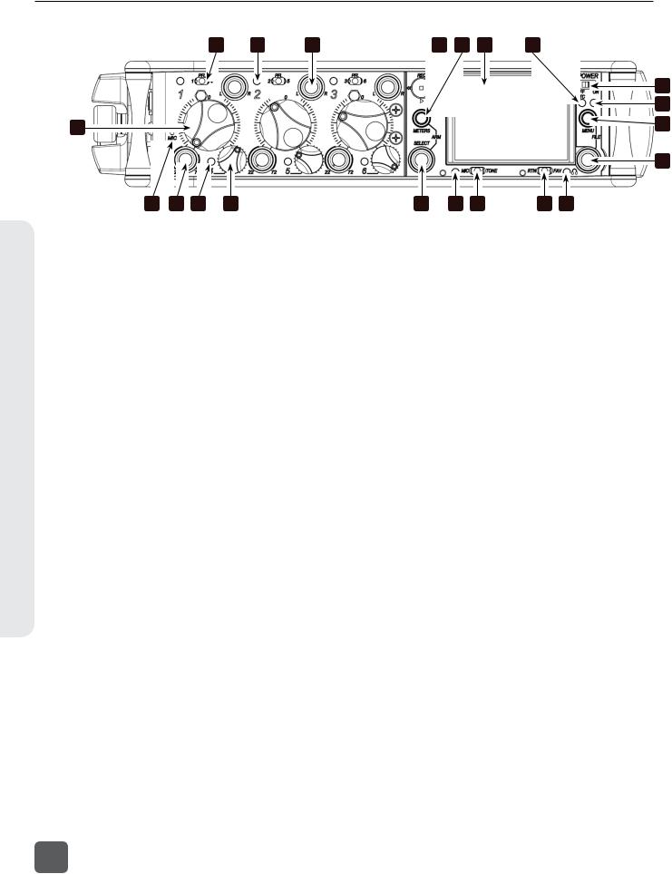
1)Input Fader
Primary control for adjusting the level of Inputs during operation. Ranges from off to +16 dB. Nominal setting is in the middle (0 dB). The three large knobs control Inputs 1, 2, and 3. The three smaller knobs along the bottom control Inputs 4, 5, and 6 (Push to recess; Push again to extend).
2)Gain / Trim (Ch.. 1 to Ch.. 3)
Coarse input gain control for Inputs 1, 2, and 3. Sets the initial input sensitivity level so that the Input Fader can be used for fine gain adjustments. Range is from +22 dB to +72 dB. Trim level for Inputs 4,
5, and 6 are controlled from the respective input Settings Screen. (See “Inputs”, page 14)
3)PFL / Input Select Switch
Slide the switch toward the indicated number to display that input’s Input Settings Screen and PFL (“solo”) the input. Does not affect Master Output signal. Slide the switch the same direction again to deactivate the PFL and return to the previous screen. To momentarily PFL an input, slide the switch toward the input’s number and hold for 1 second or more. This functionality is altered when
INPUTS > PFL Toggle Mode is set to 3ch. (See “Inputs”, page 14)
4)Input Activity LED
Indicates input signal activity. Illuminates in various colors and intensities to show signal level and activity. Green = signal presence (pre-fader), yellow = limiter activity (preand post-fader), red = signal overload/clipping (preand post-fader), flashing yellow = input PFL. Input LED’s for Inputs 1, 2, and 3 are located above the Input’s Fader knob. Input LED’s for Inputs 4, 5, and 6 are located directly left of the Input’s fader knob.
5)Input Pan (Ch.. 1 to Ch.. 3)
Controls the Left/Right balance of the input signal to the Stereo Master Bus (Push to recess; Push again to extend). Inputs 4, 5, and 6 are routed to the Left and Right mix via the respective Input Settings Screen. (See “Inputs”, page 14)
6)Transport Control
Controls the Integrated Digital Recorder. Slide up to Record, press in to Pause/ Stop, slide down to Play, slide left to Rewind, slide right to Fast Forward. (See “Recorder Setup and Control”, page 31)
7)Meters Button
Displays the Main Screen which includes metering, filename, timecode and other important information. Cycles between set meter presentations when pressed from Main Screen ((See “Meter Views”, page 10)). Returns to Main Screen from any other Screen.
Panel Descriptions
1
633 User Guide and Technical Information
Descriptions Panel
3 |
4 |
5 |
6 |
7 |
8 |
9 |
|
|
|
|
|
|
10 |
|
|
|
|
|
|
11 |
1 |
|
|
|
|
|
12 |
|
|
|
|
|
|
|
|
|
|
|
|
|
|
13 |
19 |
2 |
4 |
1 |
18 |
17 |
16 |
15 |
14 |
8)LCD
Displays contextual operating information and user interface.
9)Internal Timecode LED
When the 633 is powered down and timecode Mode is Freerun or 24-Hour Run, the Internal Timecode LED will flash blue to indicate that timecode is being maintained. The 633 will hold accurate timecode for 2 hours after being powered down.
10)Power Switch
Two-position slide switch, slides left to power the 633 off and slides right to power the 633 on.
11)Power LED
Illuminates green to indicate the 633 is powered on.
12)Menu Button
Displays the Setup Menu.
13)Headphone Encoder
Main and Input Settings Screen: Turn to adjust headphone gain. In Main Screen: Press to select Headphone Source. In Menus: Turn to navigate; Press to make selection. In Input Settings Screen: press to select input source. Headphone gain and preset selection functions can be reversed: (See “Headphone Monitoring”, page 22)
14)Headphone Clipping LED
Illuminates red to indicate headphone output is approaching clipping level.
15)RTN / FAV Switch
Slide Left to monitor RTN signal in headphones. Slide right to activate the headphone preset that has been marked as “favorite”. (See “Favorite Headphone Source”, page 24)
16)Mic / Tone Switch
Slide left to activate the Slate Microphone, slide again to deactivate. For momentary action hold for one second or longer. Slide right to activate the Tone Oscillator. Tone will latch if held for one second or longer; slide again to deactivate.
17)Slate Mic / Tone LED
Illuminates green when Slate Mic or tone is active.
18)Select Encoder
Multi-function encoder. Selects Tracks, RTN’s, and AUX buses on the Main Screen. On the Main Screen, press and hold the Select Encoder and then press the Meters Button to arm/disarm the currently highlighted track. With L, R, X1, X2, X3, X4, or RTN selected, press then turn to adjust level. Vertical Scroll in matrix windows. Turn to adjust trim level in Input Settings Screens 4-6 and inputs with AES selected. Turn to scroll cursor and press to insert a space character during text entry. Acts as shift button to access secondary functions. (See “Front Panel Button Shortcuts”, page 65)
19)Slate Microphone
The slate mic transducer. (See “Slate Mic and Tone Oscillator”, page 29)
2
v. 1.02 Features and specifications are subject to change. Visit www.sounddevices.com for the latest documentation.
633 User Guide and Technical Information
Left (Input) Panel
1 |
2 |
|||
|
|
|
|
|
|
|
|
|
|
|
|
|
|
|
|
|
|
|
|
3 |
4 |
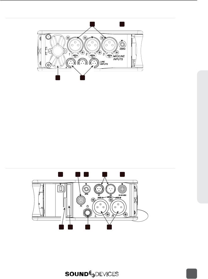
1)XLR-3F Inputs 1-3
Active-balanced analog microphoneor line-level input for inputs 1-3 on XLR-3F connector. Input type is set within the Input Settings Screen. Can supply 12V or 48V phantom power. Input 1 can also accept AES3 or AES42 (Mode 1) signal. Pin-1 ground, pin-2 (+), pin-3 (-).
2)AUX 3/4 Output
Multi-purpose auxiliary analog output. Two channels on unbalanced 3.5 mm TRS connection. Level can be adjusted from -30 dB (mic level) up to 0 dB (sufficient for driving headphones). (See “AUX 3/4 Outputs (TRS)”, page 26)
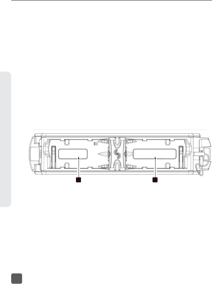
3)Battery Compartment
Holds 6 AA batteries; Three batteries in two rows held by screw cap. Top row batteries inserted with negative (-) end facing out; Bottom row batteries inserted with positive (+) end facing out.
4)TA3 Analog Line Inputs 4-6
Analog line inputs 4-6. Pin-1 ground, pin- 2 (+), pin-3 (-). Float pin 3 to unbalance.
Right (Output) Panel
1 |
2 |
|
3 |
4 |
|
5 |
|||||
|
|
|
|
|
|
|
|
|
|
|
|
|
|
|
|
|
|
|
|
|
|
|
|
|
|
|
|
|
|
|
|
|
|
|
|
|
|
|
|
|
|
|
|
|
|
|
|
|
|
|
|
|
|
|
|
|
|
|
|
Panel Descriptions
|
|
|
|
|
|
|
|
|
|
|
|
|
|
9 |
|
8 |
|
7 |
|
|
|
|
6 |
||||
|
|
|
|
|
|
|
1)USB B Connector
USB connection for keyboard or factory use.
2)Timecode I/O
Timecode input and output on 5-pin LEMO® connector.
3
633 User Guide and Technical Information
Descriptions Panel
3)RTN Input
Unbalanced stereo 3.5 mm female connector for Return audio input. Sleeve = Ground, Tip = Left, Ring = Right.
4)X1 and X2 Outputs
Line, -10, or Mic level selected in the Setup Menu section OUTPUTS. Pin-1 ground, pin-2 (+), pin-3 (-). Float pin 3 to unbalance.
5)DC Input
Accepts DC voltages from 10–18 V for powering. Pin 1 = Negative (–), pin 4 = Positive (+).
6)XLR-3M Master Outputs
Balanced analog outputs on standard 3-pin XLR-3M connectors. Mic, Line, -10, or AES (1,2 and 3,4 on L and R respectively) selectable from Setup Menu section OUTPUTS. Pin-1 ground, pin-2 (+), pin-3 (-). Unbalance by grounding pin 3 to pin 1.
Rear Panel
7)Headphone Output
1/4-inch TRS stereo headphone connector. Can drive headphones from 8 to 1000 ohm impedances to very high levels. Tip = left, ring = right, sleeve = ground.
8)CompactFlash Slot
Accepts approved CompactFlash cards with the label-side toward the rear of the 633. Compatible with Type I and Type II cards. High-speed UDMA cards are recommended for higher track count recording. See http://www.sounddevices.com/ approved for a list of approved media.
9)SD Card Slot
Accepts approved SD/SDHC/SDXC cards with the notched corner oriented toward the top of the 633. Insert until it clicks securely in the slot. The card should glide smoothly into the slot. Press to eject. See http://www.sounddevices.com/approved for a list of approved media.
B2 |
B1 |
Two battery mounts (“slots”) on the rear panel for Sony© L-Series type lithium batteries. Any capacity supported. Battery slots labeled B1 and B2 in the diagram above correspond to the labels in the Setup Menu section POWER. (See “Powering”, page 52)
4
v. 1.02 Features and specifications are subject to change. Visit www.sounddevices.com for the latest documentation.
633 User Guide and Technical Information
Quick Start Guide
This section provides a brief overview of basic 633 operation. The steps will demonstrate powering the 633, connecting an analog audio source to an input, connecting headphones, setting up monitoring, preparing media for recording, and making a recording. Refer to the rest of this user guide for full details on all 633 features.
1) Connect Power
Connect at least one power source. For external powering, connect a DC powering source (not included) to the DC connector on the Right Panel. For internal powering from AA batteries, unscrew the battery cap (counter-clockwise), insert six AA NiMH batteries (not included) the battery tubes. Orient the top three batteries with the positive (+) side facing in and the bottom three batteries with the negative (-) side facing in.
+ |
- |
+ |
- |
+ |
- |
+ |
- |
+ |
- |
|
|
2) Power On the 633
Slide the Power Switch right. The LCD will briefly display a boot screen with the Sound Devices logo and then the Main Screen will be displayed:
-
 +
+
Quick Start Guide
5
633 User Guide and Technical Information
Guide Start Quick
3) Connect Audio Source
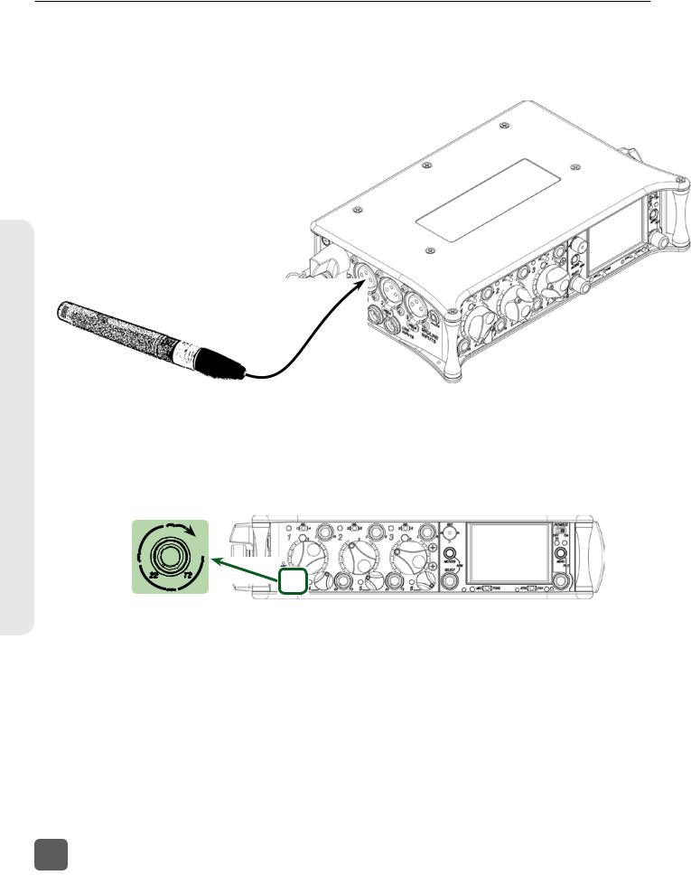
Using a standard XLR cable, connect a microphone or line level analog source to Input 1 on the left panel.
4) Power On Input
If the Input 1 trim knob is recessed, pop it up by pushing it in. If the trim knob is rotated fully counterclockwise, the input is powered off. To power the input on, rotate the trim knob clockwise until it clicks.
6
v. 1.02 Features and specifications are subject to change. Visit www.sounddevices.com for the latest documentation.

633 User Guide and Technical Information
5) Select Input Type
Slide Input 1’s the Input Select Switch left to display the Input Settings Screen for Input 1. Press the Headphone Encoder to display a list of available input types. Rotate the Headphone Encoder to select an input type and press the Headphone Encoder to select that type. Choose MIC for a dynamic microphone, MIC-PH for microphones requiring phantom power, or LINE for analog line level sources. Slide Input 1’s the Input Select Switch left again to return to the Main Screen.
6) Connect Headphones
Connect headphones to the 1/4-inch headphone output on the right panel.
Quick Start Guide
7

633 User Guide and Technical Information
Guide Start Quick
7) Select a Headphone Source
Press the Headphone Encoder to display a list of available headphone Headphone Sources. Rotate the Headphone Encoder to choose LR ST (The master left and right stereo bus), then press the HEadphone Encoder to confirm the selection.
8) Insert SD or CF Media
Open the Media Door on the right panel. The door is secured magnetically. Pull firmly to open. Insert the SD card with the bottom of the card (the side with metal contacts visible) facing toward the rear of the 633. Insert the CF card with the top of the card (the side with the manufacturer’s branding label) facing the rear of the 633.
CF card slot
SD card slot
9) Format Media
The SD or CF card must be formatted before recording. This will erase all data on the card.
1.Press the Menu Button to access the Setup Menu.
2.Rotate the Headphone Encoder to highlight FILE STORAGE.
3.Press the Headphone Encoder to access the FILE STORAGE sub-menu.
8
v. 1.02 Features and specifications are subject to change. Visit www.sounddevices.com for the latest documentation.

633 User Guide and Technical Information
4.Rotate the Headphone Encoder to highlight Erase/Format CF or Erase/Format SD.
5.Press the Headphone Encoder to begin the formatting process.
6.Press the Headphone Encoder to accept the warning messages. The formatting process will begin.
7.Press the Meters Button to return to the Main Screen.
10) Use Transport Control to Record and Stop
Slide the Transport Control up to begin recording. The background color of the Take name on the top of the Main Screen will become red and the absolute time counter on the bottom of the Main Screen will run to indicate recording is taking place.
Record (slide up)
Stop (push in)
11) Remove Media to Transfer Files
When finished recording, open the Media Door and remove the SD or CF card. To remove the SD card, push it in to release. To remove the CF card, simply pull it out. Connect the SD or CF card to any computer to transfer files.
Quick Start Guide
9
633 User Guide and Technical Information
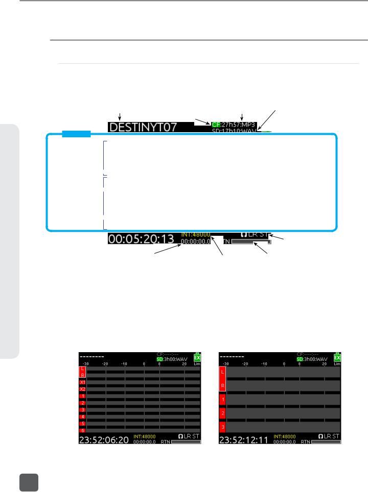
Overview Screen
Screen Overview
Primary Screen Elements
The Main Screen displays important information at-a-glance. The Main Screen can be accessed quickly from any other screen by pressing the Meters Button. Press and hold the Meters Button, then slide the RTN / FAV Switch to the left to toggle between display of timecode frame rate and sample rate.
Current take CF time remaining and audio file format SD time remaining and audio file format Active playback media
 Power source & level
Meter View
Bus tracks Unarmed track 
Armed track  Input tracks
Powered off Input 
SMPTE Timecode 
 Input limiting activity
Monitor (Headphone) information (Displays HP level during adjustment)
Absolute recording time |
Sample rate information |
RTN level |
This screen shot shows default settings. Meter Style can be changed to solid (See “Metering”, page 20) and track names can optionally be shown in the meters (See “Track Naming”, page 32).
Meter Views
Pressing the Meters Button from the Main Screen will cycle through different Meter Views on the Main Screen. There are 3 views to cycle through and each view can be set to one of four configurations from Setup Menu option SYSTEM > Meter Options: The second and third meter view can be turned off so that only one meter view is shown on the Main Screen at all times.
L, R, X1, X2, 1-6 |
L, R, 1-3 |
||
|
|
|
|
10
v. 1.02 Features and specifications are subject to change. Visit www.sounddevices.com for the latest documentation.
633 User Guide and Technical Information
L, R, 1-6 |
L, R, X1-X4, RTN |
|
|
|
|
|
|
|
|
|
|
Note that the time and date is displayed in place of the small RTN meter on the L, R, X1-X4, RTN Meter View
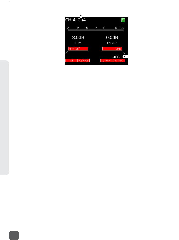
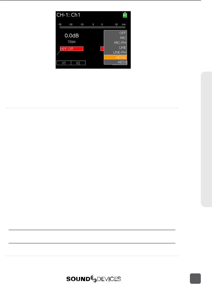
Input Settings Screen
The Input Settings Screen displays all relevant information for the selected input as well as allowing these parameters to be changed. The default method for accessing the Input Settings Screen for inputs 1-6 is to slide the Input Select Switch toward the desired input number. This functionality can be altered when Setup Menu option INPUTS > PFL Toggle Mode is set to 3ch (See “PFL Toggle Mode”, page 25).
When the Input Settings Screen is accessed, that input is soloed in the headphones (the Headphone Source is changed to PFL of the selected Input). The Headphone Source changes back to its previous source when the Input Settings Screen is exited. The Input Settings Screen can be entered without altering the Headphone Source by holding the Select Encoder down while sliding the input Select Switch. This behavior is reversed when Setup Menu option INPUTS > PFL Toggle Mode is set to 3ch
(See “PFL Toggle Mode”, page 25).
The following two screen shots are of Input 2 and Input 4, respectively. These examples demonstrate how Input Settings Screens 1-3 differ from Input Settings Screens 4-5.
1) Track Name
2) Input Number |
|
|
|
|
|
|
|
|
|
|
|
|
|
|
|
7) |
Limiter Activity |
|
|
|
|
|
|
|
|
|
|
|
|
|
|
|
|
||||
|
|
|
|
|
|
|
|
|
|
|
|
|
||||||
|
|
|
|
|
|
|
|
|
|
|
|
|
||||||
|
|
|
|
|
|
|
|
|
|
|
|
|
|
|
||||
3) Input Meter |
|
|
|
|
|
|
|
|
|
|
|
|
|
|||||
|
|
|
|
|
|
|
|
|
|
|
|
|
|
|
||||
|
|
|
|
|
|
|
|
|
|
|
|
|
||||||
|
|
|
|
|
|
|
|
|
|
|
|
|||||||
5) HPF Frequency |
|
|
|
|
|
|
|
|
|
|
|
|
|
|
|
4) |
Current Fader Gain |
|
|
|
|
|
|
|
|
|
|
|
|
|
|
|
|
||||
|
|
|
|
|
|
|
|
|
|
|
|
|
|
|
|
|||
|
|
|
|
|
|
|
|
|
|
|
|
|
|
|
8) |
Input Selection |
||
|
|
|
|
|
|
|
|
|
|
|
|
|
|
|
||||
|
|
|
|
|
|
|
|
|
|
|
|
|
|
|
||||
|
|
|
|
|
|
|
|
|
|
|
|
|
|
|
|
9) |
Headphone Source / Level |
|
|
|
|
|
|
|
|
|
|
|
|
|
|
|
|
|
|||
6) Aux Bus Assignment |
|
|
|
|
|
|
|
|
|
|
|
|
|
|
|
|
10) LR Bus Assignment |
|
|
|
|
|
|
|
|
|
|
|
|
|
|
|
|||||
|
|
|
|
|
|
|
|
|
|
|
|
|
|
|
||||
|
|
|
|
|
|
|
|
|
|
|
|
|
||||||
|
|
|
|
|
|
|
|
|
|
|
|
|
|
|
|
|
|
|
11) Input Polarity
Screen Overview
11
633 User Guide and Technical Information
Overview Screen
1) Track Name
2)Input Number 
3)Input Meter 
12)Trim Gain 
5)HPF Frequency 
6)Aux Bus Assignment 
1)Track Name
The name of the input’s ISO track. The Track Name can be edited directly from the Input Settings Screen. (See “Track Naming”, page 32)
2)Input Number
The Input’s number (1 through 6).
3)Input Meter
Displays the Input’s signal level and limiting activity. The level displayed is the level to the Iso Track and will be preor post-fader depending on the Iso Track Status. Meter ballistics can be set globally from VU or Peak+VU in Setup Menu item
SYSTEM > Meter Ballistics. (See “Metering”, page 20)
4)Current Fader Gain
The dB value of the input’s fader. (See “Trim and Fader Relationship”, page 15)
5)HPF Frequency
Displays the frequency of the Input’s high pass filter (Or HPF Off when the high pass filter is off). To adjust the high pass filter, press the Select Encoder, then turn the Select Encoder. (See “High-pass Filter”, page 17)
6)Aux Bus Assignment
Displays the status of the Input’s assignment to the X1 and X2 Output Buses. Inputs can be routed to X1 and X2 preor post-fader. Slide the Mic / Tone Switch left for the X1 bus and right for the X2 bus to cycle through the available options. Routed signal is indicated by a red background and unrouted signal by a black background. (See “Input Routing”, page 14)
 4) Current Fader Gain
 8) Input Selection
 9) Headphone Source / Level
 10) LR Bus Assignment
7)Limiter Activity
Indicates that limiting is occurring on the Input. (See “Limiters”, page 19)
8)Input Source
Displays the selected input type. To change the input type, press the Headphone Encoder, turn it to make a selection, then press it again to confirm the selection. (See “Input Types”, page 14)
9)Headphone Source / Level
Currently active Headphone Source. Displays monitor gain during adjustment. (See “Headphone Monitoring”, page 22)
10)L,R Bus Assignment
Displays the status of the Input’s assignment to the main Left and Right buses. Slide the RTN / FAV Switch to the right to toggle routing of Inputs 1, 2, and 3. Slide the RTN / FAV Switch to the left or right to toggle routing of Inputs 4, 5, and 6 to the Left or Right bus. Routed signal is indicated by a red background and unrouted signal by a black background. (See “Input Routing”, page 14)
11)Input Polarity
Slide the RTN / FAV Switch left to toggle input polarity. Available on Input 2 only. (See “Polarity”, page 17)
12)Input Trim
Displays the trim gain on inputs 4, 5, and 6 as well as any input with the source set to AES42 or AES3. Trim is adjusted on these Inputs by rotating the Select Encoder while viewing the Input Settings Screen. (See “Trim and Fader Relationship”, page 15)
12
v. 1.02 Features and specifications are subject to change. Visit www.sounddevices.com for the latest documentation.

633 User Guide and Technical Information
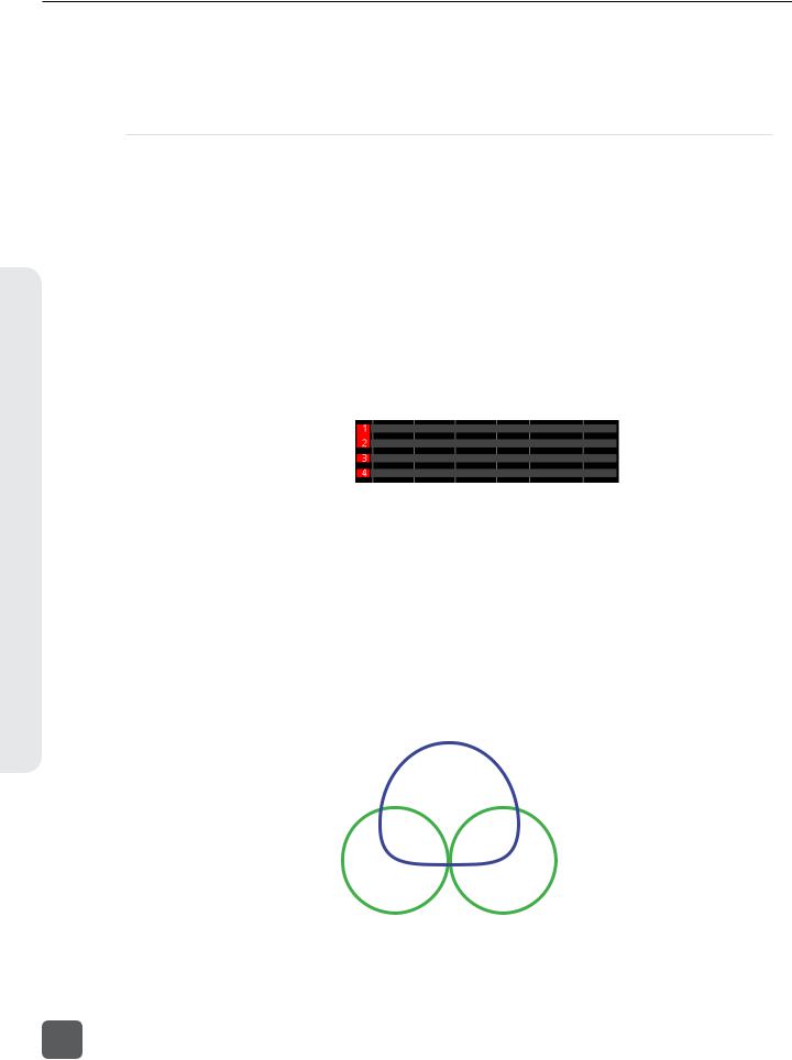
Routing Screens
Various Routing Screens are present in the 633 interface. A Routing Screen displays available source signals for routing destination tracks or outputs. An assigned route is indicated with a blue box and an unassigned route is indicated with a black box.
Sources
Assigned source |
|
|
|
|
|
|
|
|
|
|
|
|
|
|
|
|
|
|
|
|
|
|
|
|
|
|
|
|
|
|
|
Highlighter |
|
|
|
|
|
|
|
|
|
|
|
|
|
|
Destinations |
|
|
|
|
|
|
|
|
|
|
|
|
|
|
||
|
|
|
|
|
|
|
|
|
|
|
|
|
|
||
Unassigned source |
|
|
|
|
|
|
|
|
|
|
|
|
|
|
|
|
|
|
|
|
|
|
|
|
|
|
|
|
|
||
|
|
|
|
|
|
|
|
|
|
|
|
|
|
||
|
|
|
|
|
|
|
|
|
|
|
|
|
|
|
|
|
|
|
|
|
|
|
|
|
|
|
|
|
|
|
|
|
|
|
|
|
|
|
|
|
|
|
|
|
|
|
|
To edit routes in a Routing Screen:
1.Move the orange highlighter to the box to be edited. Rotate the Headphone Encoder to move the highlighter horizontally. In some Routing Screens, the Select Encoder will also move the highlighter vertically.
2.Press the Headphone Encoder to toggle the assigned state of the highlighted box.
On some Routing Screens, additional options are available and can be accessed with the Mic / Tone Switch or the RTN / FAV Switch. These options will be displayed directly above the respective switches.
Destinations
 Sources
|
|
|
|
|
|
|
|
|
|
|
|
|
|
|
|
|
|
|
|
|
|
|
|
|
|
|
|
|
|
|
|
|
|
|
|
|
|
|
|
Mic / Tone Switch options |
RTN / FAV Switch options |
||||||
LCD Daylight Mode
When engaged, LCD Daylight Mode changes the color scheme of the user interface to be more easily viewable in environments with bright ambient light or direct sunlight. LCD Daylight Mode can be engaged from the Setup Menu option SYSTEM > LCD Daylight Mode or toggled quickly by pressing and holding the Headphone Encoder then pressing the Select Encoder.
Screen Overview
13

633 User Guide and Technical Information
Inputs
The 633 has three, full-featured audio inputs on XLR-3F connectors and three additional line-level inputs on TA3 connectors. Inputs can be used as either balanced or unbalanced connections. To unbalance, tie pin-3 to pin-1 of the XLR-3M connector of the cable. There is no change in gain between unbalanced and balanced connections into the 633.
Inputs are configured from their respective input Settings Screen. The default method for accessing the Input Settings Screen for inputs 1-6 is to slide the Input Select Switch toward the desired input number. This functionality can be altered when Setup Menu option INPUTS > PFL Toggle Mode is set to 3ch (See “PFL Toggle Mode”, page 25).
Input Types
Change the input type from the Input Settings Screen (See “Input Settings Screen”, page 11).
The following table describes the available input types.
Inputs
Input Type |
Inputs Available |
Description |
|
|
OFF |
All |
Input off. |
||
|
|
|
|
|
MIC |
1, 2, 3 |
Use with dynamic microphones or other mic-level signals. |
||
|
|
|
|
|
MIC-PH |
1, 2, 3 |
Use with phantom-powered condenser microphones only. Provides 48V or |
||
12V phantom power. see Phantom Power |
||||
|
|
|||
LINE |
All |
For use with any line-level source. |
||
|
|
|
|
|
LINE-PH |
|
For use with phantom-powered condenser microphones only. Provides 48V |
||
1, 2, 3 |
or 12V phantom power, but at a line-level gain range. Useful for recording |
|||
|
|
extremely loud sounds. |
||
AES42 |
1, 2* |
Digital input with power activated for AES42 (Mode 1) digital microphones. |
||
|
|
|
|
|
AES3 |
1, 2* |
Digital input. |
||
|
|
|
|
|
* AES42 and AES3 input source option only appears in input 2 when selected as a source for input 1. Input 1 XLR-3F connector is used for digital input.
Input Routing
Each input of the 633 has a corresponding “ISO” Track that it is permanently routed to. Additionally, each Input can be independently routed to the Left (L), Right (R), Aux 1 (X1), and/or Aux
2 (X2) buses from the Input Settings Screen (See “Input Settings Screen”, page 11). Inputs are
routed to the Aux 1 (X1) and Aux 2 (X2) buses from the X1, X2 Routing Screen (Setup Menu option OUTPUTS > X1, X2 Routing) and to the Aux 3 (X3) and Aux 4 (X4) buses from the X3, X4 Routing Screen (Setup Menu option OUTPUTS > X3, X4 Routing).
Input signals are always routed to L and R tracks post-fader. The Pan Control variably adjusts the level of Input 1, 2, or 3 signal to the L and R tracks. Input signals can be routed to ISO tracks and X1, X2, X3, and X4 tracks either preor post-fader.
•Preor post-fader routing to ISO tracks is set per channel from Setup Menu section
INPUTS > Input to ISO Routing.
•Preor post-fader routing to X1 and X2 tracks is set from the Input Settings Screen. From the Input Settings Screen, slide the Mic / Tone Switch to cycle between unrouted (black background), routed post-fader (red background), and routed pre-fader (red background with PRE label).
14
v. 1.02 Features and specifications are subject to change. Visit www.sounddevices.com for the latest documentation.
633 User Guide and Technical Information
•Preor post-fader routing to the X1, X2, X3 and X4 tracks is a global setting that applies to all inputs routed to the X1, X2, X3 and X4 tracks. This option is configured from theX1, X2 Routing Screen and the X3, X4 Routing Screen.
Pan Control
The pop-up Pan Control routes Inputs 1, 2, and 3 to the left (L) and right (R) channels of the stereo Master Bus. The pan pot has a detent in the center position. After setting the pan, the pan control can be recessed to hide it from the mixing surface during normal operation.
Inputs 4, 5, and 6 are routed directly to the left (L) and/or right (R) channels of the stereo Master Bus from their respective Input Settings Screens.
Trim and Fader Relationship
The gain of an input is adjusted by two controls, Input Trim and Input Fader. This two-stage architecture is identical to the topology of large mixing consoles and provides a great deal of control. Input Trim is often thought of as a course gain control and the Input Fader as the fine gain control.
Input 1 Fader |
Input 2 Fader |
Input 3 Fader |
Inputs
|
|
|
|
|
|
|
|
|
|
|
|
|
|
|
|
|
|
|
|
|
|
|
|
|
|
|
|
|
|
|
|
|
|
|
|
Input |
|
|
|
|
Input |
|
|
|
|
Input |
|
|
|
|
Inputs 4, 5, and 6 Trim |
||
1 Trim |
|
|
2 Trim |
3 Trim |
|||||||||||||
|
|
Input |
|
|
|
|
|
Input |
|
|
Input |
|
|
||||
|
|
4 Fader |
|
|
|
5 Fader |
6 Fader |
||||||||||
Input/Trim (Analog)
Analog input sensitivity for Inputs 1, 2, and 3 is set with the pop-up Trim control knob. Analog input sensitivity for line-level Inputs 4, 5, and 6 is set by rotating the Select Encoder from the respective input’s Input Settings Screen (Off, -30 dB to 16 dB). To power down Input 1, 2, or 3 turn the respective trim control fully counter-clockwise until it clicks.
With the Input Fader set to unity gain (0 dB or 12 o’clock), make the appropriate adjustments to trim levels. Once the coarse gain is set to the desired level, press the Trim control to hide it from the 633’s mixing surface.
Input Trim (Digital)
The coarse level of a digital input is set by rotating the Select Encoder in the Input Settings Screen of an input with a digital source. The digital trim level is displayed on the LCD. The digital trim level is adjustable from -30 to +16 dB.
15
633 User Guide and Technical Information
Input Fader
Inputs
The Input Fader is the primary control used while mixing and it affects the level of the Input signal routed to all post-fader destinations. Use the Input Fader to make fine gain adjustments. The fader can be attenuated from off (full counter-clockwise position), -36.8 dB to +16 dB (full clockwise position) relative to the set Trim level. To optimize gain structure for the best performance, operate input faders at or near the 0 dB (unity gain) position.
Inputs 1, 2, and 3 use the large fader knobs. Inputs 4, 5, and 6 use the pop-up fader knobs. To power down Input 4, 5, or 6, turn the respective pop-up fader control fully counter-clockwise until it clicks.
Phantom Power
Phantom power is enabled on an input during input type selection (See “Input Types”, page 14) (See “Input Settings Screen”, page 11).
Phantom powering is a fixed DC voltage of either 12 or 48 Volts. This voltage is resistively applied to pin 2 and pin 3 of an input’s XLR-3F connector, relative to pin 1. In this configuration, there is no voltage difference between signal pins 2 and pin 3.
The phantom voltage is selectable between 12 and 48 Volts from the Setup Menu item
INPUTS > Phantom Voltage. The selected voltage level applies to all inputs with phantom power enabled. The factory default phantom power voltage is 48 V.
Digital Inputs
The 633 accepts AES3 (AES/EBU) balanced, AES42 (Mode 1) balanced, and AES3 unbalanced digital signals on the Input 1 XLR-3F connector. The 633 auto-detects between AES3 balanced and AES3 unbalanced digital signals and adjusts accordingly. Digital input gain is controlled by rotating the Select Encoder from the input’s Input Settings Screen.
Never attach unbalanced connections to an input set for AES42. This can result in damage to the hardware.
To use a digital input:
1.Enter the Input Settings Screen for Input 1. (Slide Input Select switch left or right depending on the value of Setup Menu option INPUTS > PFL Toggle Mode) (See “PFL Toggle Mode”, page 25)
2.Press the Headphone Encoder to display the list of available input sources.
3.Turn the Headphone Encoder to select AES3 or AES42
4.Press the Headphone Encoder to confirm the selection.
16
v. 1.02 Features and specifications are subject to change. Visit www.sounddevices.com for the latest documentation.
633 User Guide and Technical Information
AES digital signal carries two channels of audio. When the source of Input 1 is set to AES42 or AES3, the first channel of the AES signal is present on Input 1 and the second channel of the AES signal is available on Input 2. Selecting AES42 or AES3 source for Input 2 will connect to the second channel of the AES signal (plugged into Input 1) and disable input 2’s XLR-3F connection.
The 633’s digital inputs are sample rate converted to the internal recorder’s sample rate.
High-pass Filter
Each input channel has an adjustable High-pass Filter controlled by pressing the Select Encoder from the input’s Input Settings Screen, rotating the Select Encoder to adjust the frequency, then pressing the Select Encoder again. To disable an input’s High-pass Filter, rotate counter-clockwise until the value HPF Off is shown.
High-pass (or low-cut/low roll-off) filters are useful for removing excess low frequency energy from audio signals. Wind noise is a common unwanted low frequency signal that can be reduced with the use of a High-pass Filter. For most audio applications, engaging the High-pass Filter is beneficial, because audio information below 100 Hz is rarely used, especially for speech reproduction.
The 633’s High-pass Filter circuit features an adjustable corner (-3 dB) frequency over a range from 80 to 240 Hz. Below 80 Hz, the filter’s slope is 12 dB/octave. At higher corner frequency settings, the slope is 6 dB/octave. The purpose for this compound slope is to give additional roll-off at the 80 Hz setting to reduce wind noise and low frequency rumble. The higher settings can be used to counteract the proximity effect of directional microphones where a more gentle slope is desired.
The 633’s High-pass Filter circuit is unique because of its placement before any electronic amplification. Most mixers’ High-pass Filter circuits are placed after the microphone preamplifier, such that all of the low-frequency signals get amplified. By virtue of the 633’s circuit cutting the low-frequency signals before amplification, higher headroom is achieved in the presence of signals with significant low-frequency energy.
When possible, attempt to equalize at the sound source with microphone selection, placement, windscreens, and onboard microphone filtering. Many microphones have on-board high pass filters. Use the High-pass Filters on the 633 in conjunction with the microphone’s filter to increase the filter’s slope.
When Setup Menu option RECORDER > Sample Rate is set to 192k, the High-pass Filter is not adjustable. The available options in this mode are Off and 50Hz.
Polarity
Change the polarity of Input 2 from the Input Settings Screen (See “Input Settings Screen”, page 11).
Inputs
17
633 User Guide and Technical Information
Inputs
Polarity reversal is used to compensate for incorrectly wired balanced cables, to prevent signal cancellation when a source is dual-miked from opposite directions, or to reverse left/right with microphones in a mid-side (M/S) configuration.
Input Linking
Input pairs 1-2 and 5-6 can be linked as stereo pairs. Inputs can be linked as a standard stereo pair or as an M/S matrixed stereo pair (See “M/S Matrixing”, page 18).
When a pair of inputs is linked:
•Each channels’ Trim Control and High-Pass Filter Control work as normal, controlling coarse gain and High-pass Filtering for their respective inputs.
•The odd channel’s Input Fader controls the post-fader level of both inputs.
•The odd channel’s Pan Control controls the balance of the stereo signal to the Master Bus. When linked M/S, the odd channel’s Pan Control functions as a left/right balance control for the matrixed M/S signal.
•The even channel’s Fader Control and Pan Control are disabled.
•The limiters of both inputs are linked.
•The background label of both inputs is connected on the Main Screen.
Linked 
Unlinked 
M/S Matrixing
When input pairs are linked M/S, the odd channel is used for the Mid signal and the even channel is used for the Side signal. To produce a stereo signal from an M/S configuration, the signal from both microphones must be processed.
Mid-side (M/S) matrixing is a method for processing audio signal from a cardioid microphone and a bidirectional microphone into a stereo signal. The cardioid microphone is the “mid” signal and connects to the odd Input, and the bidirectional microphone is the “side” signal and connects to even Input. The cardioid microphone is pointed at the sound source, and the bidirectional microphone
is oriented sideways (positioned with its capsule as near as possible to the cardioid microphone’s capsule). The following diagram shows the relative polar patterns of microphones in an M/S configuration.
Mid Signal
Side Signal
18
v. 1.02 Features and specifications are subject to change. Visit www.sounddevices.com for the latest documentation.
633 User Guide and Technical Information
Limiters
Limiters prevent clipping by attenuating signals that surpass a set threshold. The amount of attenuation is defined by the “ratio” of the limiter and expressed as two numbers. All 633 limiters use a 20:1 compression ratio. This means that signal that exceeds the threshold by 20 dB will exit the limiting stage at only 1 dB above the threshold.
The time it takes for limiting to begin once signal has exceeded the threshold is referred to as the “attack time”. The time it takes for limiting to cease once signal has fallen back below the threshold is referred to as “release time”. Signals that exceed the threshold faster than the limiter’s attack time can still cause clipping. The 633 limiters have a 1 ms attack time and a 500 ms release time.
The limiters are globally activated when the Setup Menu item LIMITERS > Limiter Enable is set to Hard Knee or Soft Knee (See "Limiter Knee", page 19). This activates both the input limiters (Inputs 1 through 6) and all output limiters. Sound Devices recommends using the limiters at all times. Limiters are present on both mic and line-level inputs as well as the Master L,R tracks and the X1,X2 tracks. The default threshold of all limiters is 16 dBu and can be adjusted from 4 dBu to
18 dBu (in 1 dBu increments) from Setup Menu options LIMITERS > Input 1-6 PostFade Threshold,
LIMITERS > L,R Threshold, and LIMITERS > X1,X2 Threshold.
In normal operation, with a properly set gain structure, the threshold of the Input Limiter is rarely reached. Without Input Limiters, high signal conditions can overload a channel and cause distortion. The Input limiter is working when the respective input’s Input Activity LED illuminates yellow. Limiting activity will also be displayed as a yellow square on the right side of the input’s meter on the Main Screen. If the limiting activity is regularly indicating, reduce the amount of gain applied to the channel by turning down the Trim control.
Limiter Knee
The “knee” of the limiter determines how the limiter operates in relation to the set threshold. A “hard knee” leaves all program material below the threshold completely unaffected and attenuates only those peaks above the threshold. A “soft knee” attenuates the program material slightly before the threshold (about 6 dB) for a more gradual, tape-like sound.
The knee parameter for the 633’s limiters is set with Setup Menu option LIMITERS > Limiter Enable.
Linking Limiters
When two limiters are linked, both channels will be limited when signal reaches the threshold in any channel of the pair. Linking inputs as a stereo pair (see Input Linking) also links those inputs’ limiters. Limiters for L,R and X1,X2 channel pairs can be linked with Setup Menu options
LIMITERS > L,R Linking and LIMITERS > X1,X2 Linking.
Limiters
19
633 User Guide and Technical Information
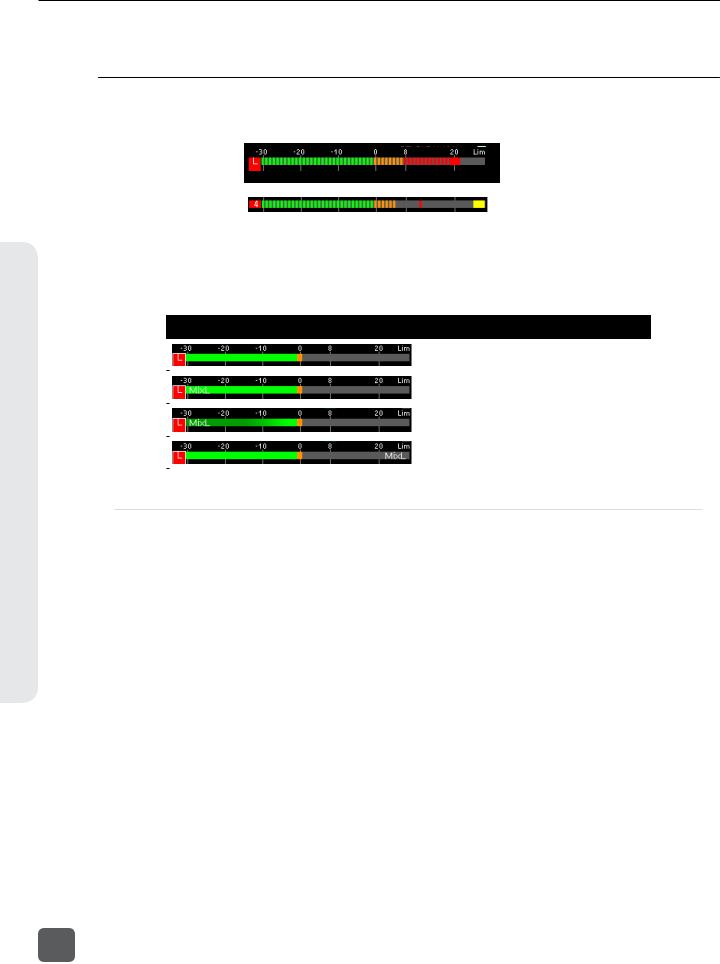
Metering
Metering
All track levels are displayed on the LCD in the Main Screen. A larger red square under the 20 dBU marker indicates clipping on the track. A large yellow square indicates limiting activity on the track.
 Input clipping
 Limiter active
Meters can be displayed with segments or solid lines (Setup Menu option
SYSTEM > Meter Display Style). Track Names can also be displayed on top of meters in various styles (Setup Menu option SYSTEM > Track Names in Meters). The following screen shots demonstrate solid meters and the available Track Name display styles.
|
Meter Appearance |
Track Name Display Style |
|
|
|
|
|
Off |
|
|
|
|
||
|
|
|
|
|
|
|
|
Left |
|
|
|
|
|
|
|
|
|
Left (w/ramp) |
|
|
|
|
|
|
|
|
|
Right |
|
|
|
|
|
|
|
|
|
|
|
Meter Ballistics
Audio meter “ballistics” is the manner in which a visual meter responds to audio signal levels. The ballistics of all 633 meters is set globally from Setup Menu option SYSTEM > Meter Ballistics. The default ballistics setting is Peak + VU.
VU
VU (volume units) meter ballistics correspond closely to how the human ear perceives loudness. This provides a good visual indication of how loud a signal will be. In VU mode, the attack and decay of the meter signal is 300 mS. VU meters provide good visual indication of how loud a signal will be, but provide poor information of actual signal peaks.
Peak + VU
The 633 can simultaneously display VU and Peak level information. In this mode the perceived loudness (VU) is displayed as a standard bar, and the Peak signal as a single, independent segment above the VU.
Peak Only
Peak-reading ballistics (PPM) correspond to actual signal peaks, but don’t necessarily correspond to perceived signal loudness. Peak meters have an instantaneous attack and a slow decay to allow visual monitoring of peak activity. Peak metering is useful when interconnecting to audio inputs on digital equipment. In the digital realm, signal overload can cause immediate distortion.
20
v. 1.02 Features and specifications are subject to change. Visit www.sounddevices.com for the latest documentation.
Loading...