


702
High Resolution Digital Audio Recorder User Guide and Technical Information firmware rev. 2.67
Sound Devices, LLC
E7556 State Rd. 23/33 • Reedsburg, WI • USA +1 (608) 524-0625 • fax: +1 (608) 524-0655 Toll-Free: (800) 505-0625 www.sounddevices.com support@sounddevices.com
backside - front cover

702 User Guide and Technical Information
Table of Contents
Quick Start Guide .. . . . . . . . . . . . . . . . . . . . . . . . . . . |
4 |
Powering the Unit |
|
Menu Navigation Basics |
|
Connecting Audio Sources |
|
Routing Inputs to Tracks |
|
Selecting Recording Parameters and File Destination |
|
Recording |
|
Playback |
|
FireWire File Transfer |
|
Front Panel Descriptions .. . . . . . . . . . . . . . . . . . . . . |
7 |
Panel Button Lock |
|
LCD Main Display Descriptions . . . . . . . . . . . . . . . |
10 |
Left Panel Connectors and Controls . . . . . . . . . . . |
12 |
Right Panel Connectors and Controls . . . . . . . . . . |
13 |
Back Panel Descriptions . . . . . . . . . . . . . . . . . . . . . |
14 |
Input Setup and Control . . . . . . . . . . . . . . . . . . . . . |
15 |
Input Source Selection |
|
Analog Inputs |
|
Input Linking (Stereo or MS Decoding) |
|
Digital Input – AES3 |
|
Digital Input – AES3id (S/PDIF) |
|
Signal Presence and Peak Indicator |
|
Input Delay |
|
Input-to-Track Routing .. . . . . . . . . . . . . . . . . . . . . . |
18 |
Routing |
|
Selective Input Muting |
|
Sampling Rate and Bit Depth . . . . . . . . . . . . . . . . . 20
Sampling Rate
Bit Depths
Word Clock . . . . . . . . . . . . . . . . . . . . . . . . . . . . . . . . 21
Clock Master
Clock Slave
C. Link – Multi-Unit Linking
Outputs – Analog and Digital . . . . . . . . . . . . . . . . . 23
Analog Output Bus |
|
Digital Output Bus |
|
Headphone Output .. . . . . . . . . . . . . . . . . . . . . . . . . |
24 |
Selecting Headphone Sources |
|
Setting Headphone Source Options |
|
MS Stereo Monitoring |
|
Rotary Switch Behavior |
|
Headphone Favorite Selection |
|
Headphone Playback Mode |
|
Headphone Warning Tones |
|
Metering and Display .. . . . . . . . . . . . . . . . . . . . . . . 26
Output Meter |
|
Meter Ballistics |
|
Peak LEDs |
|
Tone Oscillator |
|
LCD Contrast & Backlight, LED Brightness |
|
LCD Gain Display |
|
Record Indication |
|
24-Hour Time Counter.. . . . . . . . . . . . . . . . . . . . . . . |
29 |
Recording . . . . . . . . . . . . . . . . . . . . . . . . . . . . . . . . . |
30 |
Recording |
|
Pre-Record Buffer |
|
Failure During Recording |
|
Record Pause |
|
Record Timer |
|
Playback . . . . . . . . . . . . . . . . . . . . . . . . . . . . . . . . . . 32
AutoPlay |
|
Audio File Formats . . . . . . . . . . . . . . . . . . . . . . . . . |
32 |
.WAV |
|
.FLAC |
|
.MP2
.MP3 iXML
Recording Time Calculation .. .. .. .. .. .. .. .. .. .. .. .. .. .. .. .. .. .. 35
Uncompressed Recording Time in Track-Hours |
|
MP3 Compressed Record Time in Hours |
|
File Naming / Numbering .. . . . . . . . . . . . . . . . . . . . |
36 |
Scene Name/Numbering |
|
Take Numbers |
|
Mono Track Name Designators |
|
Duplicate File Names |
|
Wave Agent Beta.. . . . . . . . . . . . . . . . . . . . . . . . . . . |
38 |
File Management . . . . . . . . . . . . . . . . . . . . . . . . . . . |
39 |
Folder Actions |
|
File Viewer Screen |
|
File Time and Date |
|
File Size Maximum |
|
Setting/Clearing Flag Bits |
|
Automatic Flag Clearing |
|
File Copying Among Available Drives |
|
File Deletion |
|
False Take Control |
|
Emptying the Trash and False Take Folders |
|
Take Number Incrementing |
|
Take List |
|
Take Status |
|
CompactFlash Recording Media . . . . . . . . . . . . . . |
45 |
Formatting |
|
Speed Testing |
|
Qualified CF Cards |
|
Storage Medium – External FireWire Drives . . . . . 47
When to Use External FireWire Drives |
|
Formatting |
|
FireWire Bus Powering |
|
Qualified Drives |
|
DVD-RAM Drives |
|
File Transfer – FireWire . . . . . . . . . . . . . . . . . . . . . . |
49 |
Powering . . . . . . . . . . . . . . . . . . . . . . . . . . . . . . . . . . |
50 |
Lithium Ion Rechargeable Battery |
|
External Powering and Battery Charging |
|
Time of Day Battery |
|
Auto Functions with External Powering |
|
Power-up Messages |
|
Power Consumption Variables |
|
Firmware Upgrades . . . . . . . . . . . . . . . . . . . . . . . . . 52
Version Information
Upgrading Firmware
CL-1 Remote Control and Keyboard Interface . . . 53
Connecting the CL-1 |
|
Logic Inputs and Outputs |
|
Logic Inputs |
|
Logic Outputs |
|
702 Setup Presets .......................... |
57 |
Built-In Presets |
|
User Setup Data File |
|
Setup Menu .. . . . . . . . . . . . . . . . . . . . . . . . . . . . . . . |
59 |
Front Panel Button Shortcuts . . . . . . . . . . . . . . . . . |
66 |
Specifications .. . . . . . . . . . . . . . . . . . . . . . . . . . . . . |
68 |
Connector Pin Assignments .. . . . . . . . . . . . . . . . . |
70 |
Accessories . . . . . . . . . . . . . . . . . . . . . . . . . . . . . . . |
71 |
CE Declaration of Conformity . . . . . . . . . . . . . . . . . |
73 |
Software License . . . . . . . . . . . . . . . . . . . . . . . . . . . |
74 |
Warranty . . . . . . . . . . . . . . . . . . . . . . . . . . . . . . . . . . |
75 |
1

702 User Guide and Technical Information
Welcome
Thank you for purchasing the 702 digital recorder. The super-compact 702 records and plays back audio to and from CompactFlash, making field recording simple and fast. It writes and reads uncompressed PCM audio at 16 or 24 bits with sampling rates between 32 kHz and 192 kHz. It also writes and reads data compressed FLAC and audio compressed MP2 and MP3 files.
The 702 implements a no-compromise audio path that includes Sound Devices’ high-resolution, discrete microphone preamplifiers. Designed specifically for high bandwidth, high bit rate digital recording, these preamps set a new standard for frequency response linearity, low distortion performance, and low noise.
With documentary and ENG sound engineers in mind, the 702 is very small, while still being fea- ture-rich. No other recorder on the market matches its size and feature set. In addition, its learning curve is quite short—powerful does not mean complicated. While the 702 is a very capable recorder by itself, it truly excels when used in conjunction with an outboard audio mixer such as Sound Devices’ own 442 or 302.
Sound Devices took advantage of the best in professional and consumer electronics technologies to bring incredible feature depth with ease of use. CompactFlash media is highly reliable, industry
standard, and easily obtainable. The removable, rechargeable battery is a standard Sony-compatible Li-ion camcorder cell. The 702 interconnects with Windows and Mac OS computers via FireWire for convenient data transfer and backup.
702 Firmware Known Issues
For a complete list of known issues regarding the most current firmware please visit Sound Notes. http://www.sounddevices.com/notes/recorders/known-issues/
Copyright Notice and Release
All rights reserved. No part of this publication may be reproduced, stored in a retrieval system, or transmitted in any form or by any means, electronic, mechanical, photocopying, recording, or otherwise, without the expressed written permission of SOUND DEVICES, LLC. SOUND DEVICES is not responsible for any use of this information.
SOUND DEVICES, LLC shall not be liable to the purchaser of this product or third parties for damages, losses, costs, or expenses incurred by purchaser or third parties as a result of: accident, misuse, or abuse of this product or unauthorized modifications, repairs, or alterations to this product, or failure to strictly comply with SOUND DEVICES, LLC’s operating and installation instructions.
Microsoft Windows is registered trademarks of Microsoft Corporation. Macintosh is a registered trademark of Apple Computer. Other product and company names mentioned herein may be the trademarks of their respective owners.
The sound waves logo is a registered trademark of Sound Devices, LLC.
2
v. 2.67 Features and specifications are subject to change. Visit www.sounddevices.com for the latest documentation.

702 User Guide and Technical Information
Limitation of Liability
LIMITATION ON SOUND DEVICES’ LIABILITY. SOUND DEVICES, LLC SHALL NOT BE LIABLE TO THE PURCHASER OF THIS PRODUCT OR THIRD PARTIES FOR DAMAGES, LOSSES, COSTS, OR EXPENSES INCURRED BY PURCHASER OR THIRD PARTIES AS A RESULT OF: ACCIDENT, MISUSE, OR ABUSE OF THIS PRODUCT OR UNAUTHORIZED MODIFICATIONS, REPAIRS, OR ALTERATIONS TO THIS PRODUCT, OR FAILURE TO STRICTLY COMPLY WITH SOUND DEVICES, LLC’S OPERATING AND INSTALLATION INSTRUCTIONS. TO THE FULLEST EXTENT PERMITTED BY LAW, SOUND DEVICES SHALL HAVE NO LIABILITY TO THE END USER OR ANY OTHER PERSON FOR COSTS, EXPENSES, DIRECT DAMAGES, INCIDENTAL DAMAGES, PUNITIVE DAMAGES, SPECIAL DAMAGES, CONSEQUENTIAL DAMAGES OR OTHER DAMAGES OF ANY KIND OR NATURE WHATSOEVER ARISING OUT OF OR RELATING TO THE PRODUCTS, THESE TERMS AND CONDITIONS OR THE PARTIES’ RELATIONSHIP, INCLUDING, WITHOUT LIMITATION, DAMAGES RESULTING FROM OR RELATED TO THE DELETION OR OTHER LOSS OF AUDIO OR VIDEO RECORDINGS OR DATA, REDUCED OR DIMINISHED AUDIO OR VIDEO QUALITY OR OTHER SIMILAR AUDIO OR VIDEO DEFECTS ARISING FROM, RELATED TO OR OTHERWISE ATTRIBUTABLE TO THE PRODUCTS OR THE END USER’S USE OR OPERATION THEREOF, REGARDLESS OF WHETHER SUCH DAMAGES ARE CLAIMED UNDER CONTRACT, TORT OR ANY OTHER THEORY. “CONSEQUENTIAL DAMAGES” FOR WHICH SOUND DEVICES SHALL NOT BE LIABLE SHALL INCLUDE, WITHOUT LIMITATION, LOST PROFITS, PENALTIES, DELAY DAMAGES, LIQUIDATED DAMAGES AND OTHER DAMAGES AND LIABILITIES WHICH END USER SHALL BE OBLIGATED TO PAY OR WHICH END USER OR ANY OTHER PARTY MAY INCUR RELATED TO OR ARISING OUT OF ITS CONTRACTS WITH ITS CUSTOMERS OR OTHER THIRD PARTIES. NOTWITHSTANDING AND WITHOUT LIMITING THE FOREGOING, IN NO EVENT SHALL SOUND DEVICES BE LIABLE FOR ANY AMOUNT OF DAMAGES IN EXCESS OF AMOUNTS PAID BY THE END USER FOR THE PRODUCTS AS TO WHICH ANY LIABILITY HAS BEEN DETERMINED TO EXIST. SOUND DEVICES AND END USER EXPRESSLY AGREE THAT THE PRICE FOR THE PRODUCTS WAS DETERMINED IN CONSIDERATION OF THE LIMITATION ON LIABILITY AND DAMAGES SET FORTH HEREIN AND SUCH LIMITATION HAS BEEN SPECIFICALLY BARGAINED FOR AND CONSTITUTES AN AGREED ALLOCATION OF RISK WHICH SHALL SURVIVE THE DETERMINATION OF ANY COURT OF COMPETENT JURISDICTION THAT ANY REMEDY HEREIN FAILS OF ITS ESSENTIAL PURPOSE.
3

702 User Guide and Technical Information
Quick Start Guide
The 702 is an extremely powerful and flexible portable audio recorder. Before recording, please familiarize yourself with the product. Several settings should be verified or set based on individual recording needs.
Powering the Unit
1.Apply power to the unit by attaching the (included) removable, rechargeable Li-ion (lithium ion) battery to the back panel battery mount. The metal tabs on the mount line up with the electrical contacts on the battery. From the factory, the battery may not have a charge, so external DC may be needed for initial operation and charging. Connect the included AC-to-DC power adapter to the DC input plug to power and charge the battery.
2.Press and hold the power button to turn on the unit. Press and hold the power button to turn off the unit.
If this is the first time the recorder has been powered, or if it has been without a battery for an extended period, the date and time may need to be set.
Charge the included Li-ion battery for 6 hours prior to initial use.
Menu Navigation Basics
The Setup Menu provides options for recording, routing, and control. The single layer menu structure allows for very quick navigation and function selection. To enter the Setup Menu press the front panel menu 
 button. Once in the Setup Menu, the following conventions are shared for navigating among selections and to select specific parameters.
•
 - enters Setup Menu
•ITEM - highlighted menu item
•4 - selects highlighted item or parameter
• - moves up in menu and between menu parameters
• - moves down in menu and between menu parameters
•8 - exits the selected function or Setup Menu altogether
•The  stop button will exit from any menu and cancel any changes. Use it to escape out of the Setup Menu.
The right panel Rotary Switch (labeled “Select”) is a convenient control to quickly navigate among menu items and item options. Its push-to-select function duplicates the check mark in most menus.
Connecting Audio Sources
1.Connect audio sources, either analog or digital, to the appropriate input connector.
2.Set the appropriate input level—mic, line, or digital (input 1)—with the adjacent slide switch.
3.If mic-level inputs are used make certain that phantom power, input limiters, and high-pass filters are activated as required.
4
v. 2.67 Features and specifications are subject to change. Visit www.sounddevices.com for the latest documentation.

702 User Guide and Technical Information
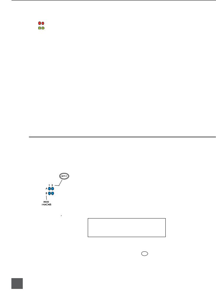
Routing Inputs to Tracks
Before recording, inputs must be assigned to tracks. Each 702 input (1 and 2) can be assigned to the two recorded tracks (A and B). These 16 possible routing combinations are shown on the front panel with 4 blue LEDs. Illuminated LEDs indicate input-to-track assignment.
1.Press and hold the  STOP button then press the
  INPUT button to cycle through factory routing presets. The 702 has several often-used presets for
 quick setup of input-to-track routing combinations. Note the routing combinations on the blue LEDs with each successive press.
2.If none of the preset routing combinations are suitable, assign a custom routing. Sequential presses of the  input button will eventually cycle to the custom routing option (see Input to Track Routing, pg. 18). From the custom input routing menu any input can be assigned to any track, including multiple inputs assigned to a single track.
3.Press EXIT to leave input routing mode.
If no input is assigned to a track the 702 will not record.
Selecting Recording Parameters and File Destination
For most productions, the general recording parameters of bit depth, sampling rate, and file format are infrequently changed. Enter the Setup Menu to verify recording settings. Bit depth and sampling rate are displayed on the LCD panel.
1.Select the bit depth as needed.
2.Set the sampling rate as needed.
3.Select the file type, WAV mono or WAV poly, FLAC, MP2, or MP3.
4.Select the storage medium(s) (CompactFlash, External drive, or any combinations of the two drives) for recording.
Recording
With file parameters set, the 702 is ready to record. The 702 is a record-priority device—pressing the record button cancels all functions, except file-based operations, and immediately begins recording a new sound file. When record is pressed, the red record LED illuminates to confirm that the unit is recording. The file name on the LCD display shows the currently recorded sound file. Press and hold the 

 STOP button to end recording.
Playback
When recording is stopped, the most recently recorded file is immediately available for playback. Press the 


 button to start file playback from the beginning of the file.
To select files for playback:
1.Press and hold the 
 button to enter the File Viewer and navigate among sound files and folders for playback. The folder of where the most recent file was recorded is opened when the
 button is pressed.
2.Use either the Rotary Switch or the arrow soft-buttons, to navigate through file folders.
3.Once a file is highlighted, press the 


 play button to begin playback.
When playback has finished, the filename will flash on the LCD display. Use the 


 fast-forward button or
 rewind button to step through files in the folder, or press the
 stop button to exit playback mode.
5

702 User Guide and Technical Information
FireWire File Transfer
Sound Devices strongly recommends shutting down equipment before connecting to or from any FireWire device with a connection that carries power (6-pin). Reports have come to our attention of isolated problems when hot-plugging IEEE 1394 (FireWire) devices. (Hot-plugging refers to making the connections when one or more of the devices—including the computer—is on.) When hot-plugging, there are rare occurrences where either the FireWire device or the FireWire port on the host computer is rendered permanently inoperable. From our experience, any FireWire connection which carries power is susceptible to this type of damage.
When connected via FireWire (IEEE-1394a) to a Mac OS or Windows OS computer (see Specifications for computer requirements), the CompactFlash card mounts onto a computer as “letter” accessible, removable storage media. This effectively makes the 702 a card reader for CompactFlash cards. Use the appropriate FireWire cable (6-pin to 4-pin or 6-pin to 6-pin) for interconnection. From the computer files on the 702 CF card can be treated as if they are local files, including renaming files, copying, deleting and playing directly through the 702.
In general, it is good practice to transfer sound files from the 702 to a computer before any processing is performed on the files.
To connect the 702 for FireWire transfer:
1.Stop all playback and recording, then shut down the recorder
2.Make certain the 702 battery is fully charged, or that the unit is connected to external DC.
3.Connect the 702 to the host computer with a FireWire cable.
4.Power the 702.
5.Initiate connection to the computer by accessing the FIREWIRE: CONNECTION menu option in the Setup Menu. Select COMPUTER/CONNECT or if this has already been selected simply hit STOP then the
HDD key to initiate connection a to the computer. The 702 will enter FireWire transfer, indicated by FIREWIRE CONNECTION on the LCD display. All functions of the 702 are stopped while the 702 is connected to a computer through FireWire.
6.Navigate to the attached drive from the computer and copy all needed sound files to local storage on the computer.
To avoid possible corruption of data on the CompactFlash card, do not interrupt the connection process and always properly dismount (eject) the drives from the operating system. On Mac OS platforms, drag the drive icons to the trash. On Windows platforms, right-click the 702 volume and choose eject.
Dismount the 702 after file transfer by “ejecting” the volume from the computer. In Mac OS, drag the disk icon from the desktop to the trash or hit  -e. In Windows OS, highlight the disk icon, right-click, and select “eject”. It is best practice to “eject” the 702 volume from the computer to maintain file integrity (see FireWire File Transfer).
6
v. 2.67 Features and specifications are subject to change. Visit www.sounddevices.com for the latest documentation.

702 User Guide and Technical Information
Front Panel Descriptions
All 702 settings can be accessed and monitored through the front panel LCD and navigation buttons. This allows the unit to be placed in a production bag along with field mixers, wireless transmitters, and wireless receivers.
1 |
2 |
|
3 |
4 |
|
|
5 |
|
6 |
7 |
8 |
9 |
10 |
11 |
29 |
|
|
|
|
|
|
|
|
|
|
|
|
|
12 |
|
|
|
|
|
|
|
|
|
|
|
|
|
|
|
28 |
|
|
|
|
|
|
|
|
|
|
|
702 |
|
|
|
|
|
|
|
|
|
|
|
|
|
|
|
|
|
27 |
|
|
|
|
|
|
|
|
|
|
|
|
|
|
26 |
|
|
|
|
|
|
|
|
|
|
|
|
|
|
25 |
|
|
|
|
|
|
|
|
|
|
|
|
|
|
24 |
23 |
22 |
21 |
20 |
19 |
18 |
17 |
16 |
15 |
|
14 |
|
13 |
|
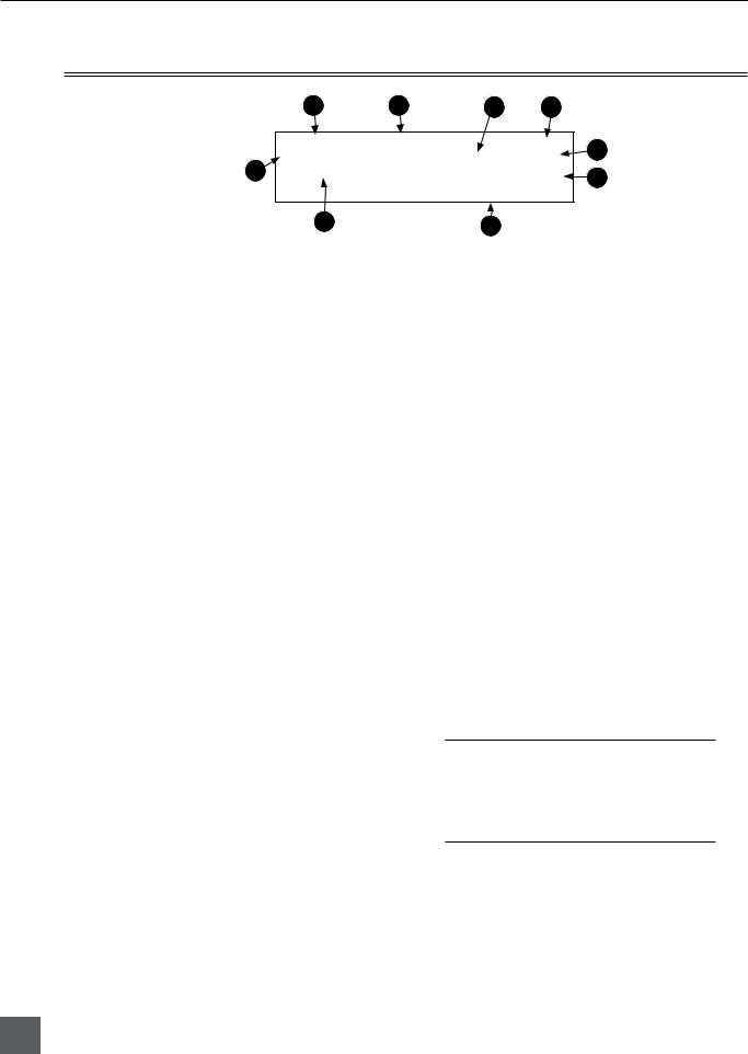
1) Digital Input LEDs
Indicates the presence of AES or SPDIFdigital signal on the respective input. When flashing, indicates that digital input is selected but no valid digital word clock signal is present.
2) Input 1 Gain
Controls the analog gain (input trim) of the channel 1 input. Normal mic input range is from 25 dB to 70 dB, low gain mic range is from 10 dB to 55 dB, line input range is from −6 dB to 18 dB. For line-level inputs, this control can be defeated for setup-menu-controlled gain. If the LCD display shows “locked” when the control is rotated, gain control of the line-level input is menu-controlled. When inputs are linked as a stereo pair, Input 1 Gain controls the gain of both inputs.
3) Input 2 Gain
Controls input 2 gain, as in #2 above. When inputs are linked as a stereo pair, Input 2 Gain adjusts left-to-right balance.
4) MENU Button
Used to access all 702 Setup Menu selections. When in menu mode, used to move up through the menu selections.
5) LCD Display
Primary display of the 702. The LCD is backlit using the LCD backlight control (#15).
6) Tone Oscillator
Press to activate the tone oscillator, press and hold for two seconds or longer to latch on, press again to deactivate. Frequency, tone level, and routing are controlled in the Setup Menu. When in the Setup Menu use the TONE key to enter Setup Menu options and select parameters when the check mark appears in the upper right hand corner of the LCD.
7) Input-to-Track Matrix LEDs
Blue LEDs indicate inputs (1 and 2) enabled for recording to tracks (A and B). A solid blue LED indicates an input is routed to a track. A flashing LED during “custom” routing mode shows the selected input/track combination.
8) INPUT Select Button
Pressing the INPUT button brings up the input muting and routing menu. Hold down the INPUT button and press one of the indicated soft buttons to mute inputs. Pressing the STOP button and the INPUT select button cycles through the four factory preset input-to-track routing combinations plus the custom routing menu. In the custom routing menu any input can be routed to any track. See Input-to-Track Routing.
7

702 User Guide and Technical Information
9) Level Meter LEDs
Two 19-segment track level-meters indicate level in dBFS. Metering ballistics are selected in the Setup Menu.
10) Power Button
Press and hold to power up the 702. Press and hold to power down.
11) Charge LED
Indicates the charge status of the onboard battery charger. LED flashes when external power is connected and the removable battery is charging; illuminates solid when battery is fully charged.
12) Power LED
Indicates the 702 is powered and available for operation. LED flashes when the removable battery or external DC is in a low-voltage condition.
13) Record Button
Press to record. The 702 is a recordpriority device; pressing this button starts recording and discontinues all other functions, except file operations. Pressing button during recording can set a cue marker or start a new file, as selected in the Setup Menu.
14) Stop/Pause Button
Press and hold this key for 150 ms to stop recording. In Record Pause mode the STOP key will pause the recording, pressing it twice will finalize the recording. In playback mode, a single press pauses playback (play-pause), allowing audio scrubbing with the FF and REW keys. Another press of the key enters play-stop mode where the FF and REW keys select files for playback from the current directory. One more press of the key exits playback mode. In the setup menu the stop key is also used to exit from any menu, returning to the main display.
15) LCD Backlight Button
Press to toggle LCD and button-board backlighting. Hold the button and turn the Rotary Switch to adjust the brightness of LEDs. In menu mode, functions as the soft-button to cancel a selection.
16) Fast-Forward Button
Performs fast-forward (FF) scrubbing through a playing sound file when pressed in playback and play-pause mode. Play-pause indicated by flashing A-time on LCD. Fast forward rate increases the longer the button is held. In play-stop mode (indicated by flashing filename on LCD) selects the next file in the record folder (either daily folder or main folder).
17) Play Button
Plays the sound file displayed in the LCD. If pressed immediately after recording is stopped, the most recently recorded file begins playback.
18) Rewind Button
Performs reverse (REW) scrubbing through a playing sound file when pressed in playback and play-pause mode. Play-pause indicated by flashing A-time on LCD. Reverse playback rate increases the longer the button is held. In play-stop mode (indicated by flashing filename on LCD) selects the previous file in the record folder (either daily folder or main folder).
19) HDD (File Viewer) Button
Press to enter the File Viewer. Pressing simultaneously with the MENU button opens the time code jam menu.
20) Headphone Output Peak LED
Indicates overload of the headphone amplifier. When lit, the headphone circuit is overloading. Reduce headphone level.
21) LIM LED
Indicates that the microphone input limiters are on. This LED does not show input limiting activity (see descriptor #27, Microphone Input Limiter LEDs).
22) Link LED
Indicates that channels 1 and 2 are linked as a stereo pair. In link mode input 1 potentiometer controls gain, input 2 potentiometer controls left-to-right balance. Inputs can be linked as either a stereo L/R pair or as a a Mid-Side (MS) pair.
8
v. 2.67 Features and specifications are subject to change. Visit www.sounddevices.com for the latest documentation.
702 User Guide and Technical Information
Front Panel Descriptions Cont.
23) Media Ready LEDs
Indicates storage media is present and available to record; CF (CompactFlash), EX (external Firewire device) [EX not available in firmware version 1.xx]. Flashing indicates media problem.
24) Media Activity LEDs
Indicates storage media read/write activity. CF (CompactFlash), EX (external Firewire device) [EX not available in firmware version 1.xx]. Do not remove power until all media activity LED’s are off.
25) High-Pass Filter LEDs
Indicates that the high-pass (low-cut) filter is active for the input. High-pass only operates when the input is set to microphone level.
26) Phantom Power LEDs
Indicates that phantom power (48 volts) is active for the individual input. Phantom can be applied to microphone or line-level signals (menu-selected).
27) Microphone Input Limiter LEDs
Illuminates orange when limiting is occurring on the microphone input. If constantly lit, the microphone input is being hit with too “hot” of a signal. Reduce the input sensitivity until limiting occurs infrequently.
28) Input Signal Presence LEDs
Indicates presence of analog or digital signal and its relative level on each of the four inputs.
29) Input Peak (Overload) LED
Indicates analog signal is approaching clipping (–3 dBFS) on each of the inputs. Additionally, flashes to indicate that an input is muted.
Panel Button Lock
Press and hold the backlight button then the tone button to bring up the Button Lock screen. Button Lock prevents accidental changes to settings or record status. The 702 displays any button lock options enabled.
select the soft buttons to activate the appropriate button lock mode
There are three modes:
•Unlocked – all buttons are accessible and operate normally.
•Non-Transport Lock – All front panel controls are locked except the Record, Stop, Play, Rewind and Fast Forward.
•Lock All – All front panel buttons are locked except the Record button. The Record button is kept active so the user can initiate recording after entering this mode and enter cue markers. To stop recording in this mode, you must disengage the panel lock and hit the stop button.
9
702 User Guide and Technical Information
LCD Main Display Descriptions
1 |
2 |
3 |
4 |
|
|
|
5 |
9 |
|
|
6 |
|
|
|
|
|
8 |
7 |
|
|
|
|
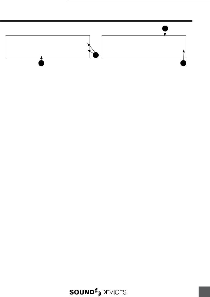
1) Battery Level Indicator
Shows the voltage level of either the removable Li-ion battery or external power sources. External power overrides battery power when present. Graphical bar for relative level and numeric indicator for precise voltage measurement.
2) File Name Display
Shows the file name actively being recorded or played back. In playback-stop mode, a flashing file name indicates that the fast-forward and rewind buttons can be used to step through files in the current playback folder.
3) Absolute Time (A-time) Display
Shows the elapsed time of the file being recorded or played back. Flashes in playback pause mode. In this mode the FF/REW keys will scrub through an open audio file. This display can be set to reverse or flash during recording. Flashes in playback-pause mode. The A-time and the 24-Hour Time Counter display can be exchanged if a large 24Hour Time Counter display is needed.
4) Time & Date Display
Alternating display between the set date and time of the 702. This information is written as the creation and modification date for recorded sound files.
5) Bit Depth Indicator
Shows the set record bit depth. In playback, shows the file bit depth.
6) Sampling Rate Indicator
Shows the set record sampling rate. In playback shows the file sampling rate.
7) Headphone Source Display
Indicates the source for headphone output. Sources and selection order are user selectable in the Setup Menu.
8) External Media Space Status (space remaining/record ready)
Bar graph indicates amount of record time remaining on external FireWire media. Numbers show time in hours and minutes based on the presently selected number of record tracks, sample frequency, bit rate, and file type.
9) CompactFlash Status
(space remaining/record ready)
Bar graph indicates amount of record time remaining on the inserted CompactFlash card. Time remaining is shown in hours and minutes based on the presently selected number of record tracks, sampling rate, bit depth, and file type.
For both media types, an asterisk in front of the media indicates that it is selected for recording. Highlighted volume indicates media selected for record monitoring, playback or file folder display.
10
v. 2.67 Features and specifications are subject to change. Visit www.sounddevices.com for the latest documentation.
702 User Guide and Technical Information
LCD Main Display Descriptions Cont.
12
11
10
10) 24-Hour Time Counter
24-Hour time is displayed when the Setup Menu option TIME COUNTER: MODE
is set to 24h. The A-time and the 24Hour Time Counter display can be exchanged if a large 24-Hour Time Counter display is needed. See 24-Hour Time Counter for details.
11) Input 1/2 Level
When input 1 or 2 gain is turned this indicates the gain level in dB for inputs 1 and 2. Gain levels can be selected to
always be displayed in the Setup Menu option LCD: GAIN DISPLAY. Normal
mic input gain range is from 26 dB to 70 dB, low gain mic range is from 10 dB to 50 dB, line input range is from −6 dB to 18 dB. “Locked” will be displayed on the LCD when the pot is turned with digital inputs selected or with line inputs set to menu control.
13
12) Cue Marker Display
In record mode, indicates when cue markers are set. Markers set by pressing the record key (option must be selected in setup menu). In playback mode, displays cue points numerically as they are reached in a file.
13) External Digital Clock Indicator
The 702 is locked to a valid external digital or word clock source when the L is in the display.
11

702 User Guide and Technical Information
Left Panel Connectors and Controls
3
1 |
2 |
1) XLR Input 1/AES3 Input 1&2
Dual function input connection. Input type set with switch above. Active-bal- anced analog microphoneor line-level input for input 1. Transformer-balanced two-channel AES3 input (1 and 2).
2) XLR Input 2
Active-balanced analog microphoneor line-level input for input 2.
3) Mic-Line Input Switch
Selects the input level and mode of the associated XLR input connector. Input 1 also can be selected for AES3 input.
4) TA3 Master (L/R) Analog Outputs
Active-balanced, line-level analog L/R outputs for the Master Output Bus. Program source and attenuation level are user selectable. Pin-1 ground, pin-2 (+), pin-3 (–).
4 5
76
5)Headphone Output
3.5 mm TRS stereo headphone connector. Can drive headphones from 8 to 1000 ohm impedances to very high levels. Tip-left, ring-right, sleeve-ground.
6)Headphone Level
Adjusts the headphone output level. NOTE: the 702 is capable of producing ear-damaging levels in headphones.
7) Tape Output
Unbalanced tape (–10 dBv nominal) output on 3.5 mm TRS stereo connector. Signal source is identical to the Master Output Bus. Tip-left, ring-right, sleeveground.
12
v. 2.67 Features and specifications are subject to change. Visit www.sounddevices.com for the latest documentation.
702 User Guide and Technical Information
Right Panel Connectors and Controls
1 |
2 |
3 |
|
|
|
|
|
|
|
|
|||||||||||||||||||
|
|
|
|
|
|
|
|
|
|
|
|
|
|
|
|
|
|
|
|
|
|
|
|
|
|
|
|
|
|
|
|
|
|
|
|
|
|
|
|
|
|
|
|
|
|
|
|
|
|
|
|
|
|
|
|
|
|
|
|
|
|
|
|
|
|
|
|
|
|
|
|
|
|
|
|
|
|
|
|
|
|
|
|
|
|
|
|
|
|
|
|
|
|
|
|
|
|
|
|
|
|
|
|
|
|
|
|
|
|
|
|
|
|
|
|
|
|
|
|
7 |
6 |
5 |
4 |
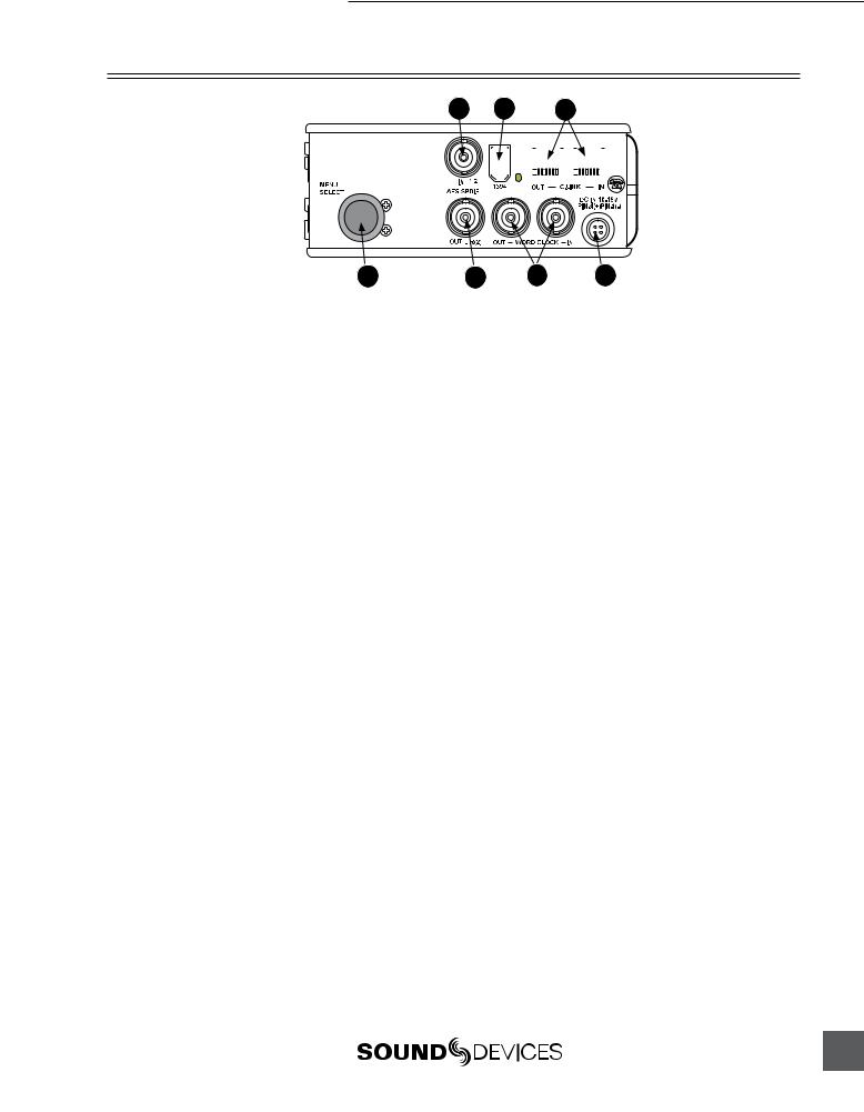
1) AES3id Input
Unbalanced digital input accepta two channel AES3 (or S/PDIF) on BNC connectors. Supports sample rates up to 200 kHz.
2) FireWire (IEEE-1394) Port
Connection to a computer (Mac OS, Windows 2k/XP, Vista, Linux) to access the CompactFlash volume as a mass storage devices. Also used to attach external FAT32-formatted FireWire drives to the 702 for direct recording and copying.
3) C. Link In/Out Ports
RS-232 protocol interface on 6-pin modular (“RJ-12”) connector for linking multiple 7-Series recorders together. Word clock and machine transport are over C. Link.
4) External DC In
Accepts sources of 10–18 volts DC for unit powering and removable Li-ion battery charging. The Hirose 4-pin connector is wired pin-1 negative (−), pin-4 positive (+). Pin-2 (−) and pin-3 (+) are used to charge the removable Li-ion battery. DC ground at both pins-1 and 2 is at the same potential as chassis and signal ground.
5) Word Clock Input and Out
Provides clock input and output for the 702. Word input accepts sample rates between 32 kHz and 192 kHz. Word clock output is the rate that box is running. There is no sample rate conversion utility in the 702.
6) AES3id Output
Unbalanced digital output, two-channel, for Output Bus 2. Signal source is menuselected.
7) Rotary Switch
When in the Setup Menu, the Rotary Switch moves among menu items; push to enter a selection or to enter data. In record and playback modes, rotate to select headphone monitor source; push action is user selectable.
13
702 User Guide and Technical Information
Back Panel Descriptions
1 |
2 |
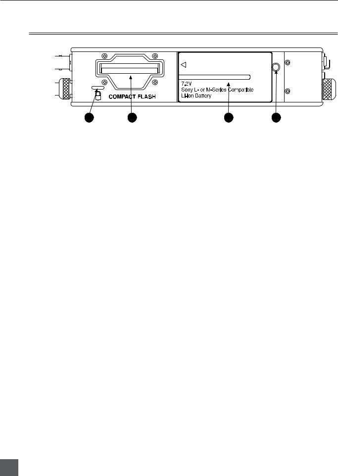
1) Security Slot
Compatible with the Kensington® Security Slot specification. Useful for securing the recorder to a fixed object with a compatible computer lock.
2) CompactFlash Slot
Accepts CompactFlash cards with the
label-side up. Compatible with Type I,
Type II, and MicroDrives.
3 |
4 |
3) Battery Mount
Accepts Sony® InfoLithium L- or M- Series removable batteries. Also accepts batteries conforming to this mount. Various capacities, from 1500 mAh to 7000 mAh are available.
4) Battery Release Pin
Push down the pin with a long skinny object such as a key, screwdriver, or a pen. With the pin pushed in, slide the L- or M-Series battery to the right to release the battery
14
v. 2.67 Features and specifications are subject to change. Visit www.sounddevices.com for the latest documentation.

702 User Guide and Technical Information
Input Setup and Control
The 702 has two inputs and two record tracks. Inputs are selectable between analog or digital sources. Analog inputs are connected with the balanced XLR connectors; digital inputs can be connected to either XLR Input 1 (AES3) or the BNC input (AES3id).
Input Source Selection
Input types are selected in pairs. Each input pair accepts analog or digital audio. The XLR input signal is selected with slide switch above the connector.
Manually selecting the audio source is used to force the inputs to analog while using an AES3 or AES3id input to lock the 702 to an external sample rate.
Digital sources connected to AES3id BNC inputs override analog signals on the corresponding XLR input. The BNC input signal type is set in the menu settings INPUT1,2:SOURCE. For most situations
the appropriate setting is auto select—the 702 will choose the input type based on signal present.
The 702 is capable of off-speed sample rates when clocked from either external digital inputs or the word clock input.
Input sources can be set to “disabled (power save)”. This option shuts down all circuitry associated with the inputs to reduce power draw and extend battery runtime during playback. When an input pair is disabled, the digital input LEDs associated with the pair will flash.
Analog Inputs
Analog inputs 1 and 2, on XLR connectors, are the primary connections into the recorder. These inputs accept balanced or unbalanced micor line-level inputs. When at mic-level, gain is controlled by the front panel potentiometers. Gain for the line level inputs can be controlled by the front panel potentiometers or menu settings. Line input gain is controlled in 0.1 dB steps.
A digital input present on the BNC inputs will override an analog signal present on the XLR inputs unless the input source is set to analog in the setup menu.
In the setup menu, the following functions can be controlled for analog inputs 1 and 2:
Phantom Power
Phantom power (48 volts) can be activated for inputs 1 and 2. When active, phantom is indicated by front panel LEDs (

 ).
).
Phantom power is available for both micand line-level inputs. Using line-level inputs with microphones is useful in high SPL environments such as concert recording. Make certain to turn off phantom power with line level output devices susceptible to damage from DC.
Shortcut: To toggle phantom power without entering the menus, press and hold the tone key then press the menu key for channel 1. Channel 2 phantom can be toggled by pressing the tone key then pressing the HDD key. If the inputs are in line level mode, phantom power will not activate from the shortcut keys and must be activated from the menus. Phantom power is linked when the inputs are linked. (See Input Linking)
15

702 User Guide and Technical Information
Input Limiters (mic-level only)
Microphone inputs 1 and 2 each have a limiter circuit designed to prevent input overload. In normal operation, with proper gain settings, the limiters should rarely engage. When activated, these limiters will prevent unusually high input signal levels from clipping the analog input stage of the preamp. The front panel LIM LED (
 ) shows that the limiter is engaged. Limiter activity is
indicated by additional front panel LEDs, one for each input channel (
 ). The input limiters are active only with mic-level inputs. The limiters are engaged by (factory) default.
When limiters are engaged, audio on channels 1 and 2 is limited to −6 dBFS.
Microphone Level Control
Microphone gain is controlled by the front panel recessed knobs. The gain control adjusts an analog gain stage and functions similarly to the input trim on a mixing console or stand-alone microphone preamplifier. Gain is controllable over two ranges, normal and low.
Gain Range (microphone-level only)
The microphone inputs operate in four gain ranges, NORMAL, NORMAL FADES TO OFF, LOW, and LOW FADES TO OFF. The NORMAL range controls input gain from 24.3 dB to 67.4 dB of gain.
The LOW range controls input gain from 9.3 dB to 52.4 dB. The LOW ranges are useful for high
SPL recording environments. The fade to off options allow for fader-like control of your gain. NORMAL FADES TO OFF provides a gain range of off or 0 to 67.4 dB and LOW FADES TO OFF pro-
vides a gain range of off or 0 to 52.4 dB.
High-Pass Filters (microphone-level only)
The high pass filters on the microphone inputs use a combination of analog and digital filters to reduce sensitivity to low frequency signals. When the high-pass is engaged on an input, its front-panel LED illuminates to indicate it is active ( 

 ). The first pole of the high-pass circuit is an analog filter at 40 Hz, 6 dB per octave and is part of the microphone preamplifier circuit. Additional poles of high-pass filtering are done in DSP.
Several frequency and slope combinations are selectable, including corner frequencies of 40, 80, 160, or 240 Hz, and filter slopes of 12 dB, 18 dB, or 24 dB per octave. The high-pass is selected for each input independently.
Shortcut: The filters can be toggled with a two-key combination. Press and hold the  LCD backlight key and press the
 menu key for channel 1 high-pass. Press and hold the
  LCD backlight key and press the
 HDD key to toggle channel 2 high-pass. The high pass filters are linked when the inputs are linked. (See Input Linking)
Line-Level Gain Control
When in line-level position, the gain for inputs 1 and 2 is controlled by the front panel recessed
potentiometers or by a menu sensitivity setting. When set for front panel control in the user menu, LINEINPUT1:GAIN and LINEINPUT2:GAIN controls in the user menu are lined out and not acces-
sible.
16
v. 2.67 Features and specifications are subject to change. Visit www.sounddevices.com for the latest documentation.

702 User Guide and Technical Information
Input Linking (Stereo or MS Decoding)
Analog inputs 1 and 2 can be linked as a stereo pair. When linked, the channel 1 front panel potentiometer controls the signal level of both inputs, and the channel 2 pot controls the left-to-right balance of the pair. When the inputs are linked, their peak limiters are linked, as well.
When set to link as an MS pair, the inputs are decoded as left/right stereo, where the gain and balance for the pair work the same as stereo linking above. Input 1 is for Mid signal, input 2 for Side signal.
When the inputs are linked, phantom power and the high pass filters also act as linked pairs. Engagging and disengaging phantom power or the high pass filters on input one will force the same function upon input two. Engaging or disengaging phantom power or the high pass filter on input two causes no effect on input one.
If MS stereo linking is selected for inputs, program sent to tracks and headphones will be L/R stereo program. To record discrete M and S signals, do not link for MS, but monitor the MS signal in headphones.
Things to consider when Linking Input 1,2 as MS:
•Digital Inputs cannot be linked as an MS pair.
•If linking Line Inputs as an MS pair, the Setup Menu option LINE INPUT 1,2: GAIN CTRL must be set to Use Front Panel Knobs.
Digital Input – AES3
The 702 accepts AES3 (AES/EBU) balanced digital at the input 1 XLR connector. Digital input is two- channel—AES3 signals on XLR-1 appear at inputs 1 and 2. To use the AES3 input, the input modeselect switch must be set to AES/EBU. There is no level control for AES inputs.


 The front panel digital input LEDs illuminate when digital signal is selected as input. If the LED is flashing, digital input is selected but a no valid digital clock is being received.
Digital Input – AES3id (S/PDIF)
The 702 accepts AES3id and S/PDIF unbalanced digital signals on the BNC connector. The 702 will auto detect the type of digital signal and adjust accordingly. Like AES3 signals, this is two channel input. There is no level control for AES3id inputs.
AES3id inputs override analog signals present at the XLR inputs. To use analog sources while using the AES3id signal as a digital clock source, select analog in the input source menu selection.
When a digital signal is present, the 702 locks its sample rate to its source frequency. This lock is indicated by a highlighted block on the main LCD display to the right of the bit depth and sample rate indicators. Recording bit depth is independent of the external digital source.
When locking the 702 to an external digital signal, be certain the source is stable. Loss of digital signal will cause the 702 to revert to its internally set sample rate, even while recording. The portion of the file recorded after the loss of signal may not play back properly. Once recording has begun, unused digital inputs are muted, digital signals that appear on them after the record button has been pressed will not be recorded or affect the sample rate of the 702.
The 702 clocks itself to the first digital signal presented to it. If the 702 detects a digital signal on the BNC inputs and locks to that signal, a digital signal applied to the XLR input will be ignored until the first digital signal is removed.
17
702 User Guide and Technical Information
Signal Presence and Peak Indicator
The signal presence and peak indicators show audio activity before input-to-track routing. Input signal presence LED’s illuminate when a –50 dBFS or greater signal is present. Input signal peak LEDs illuminate when signal levels reach –3 dBFS or greater.
Input Delay
A digital delay is selectable on each channel of the 702. Delay time per input is selectable in tenths of a millisecond (0.1 msec) steps. The Rotary Switch and menu arrows are accelerated. The more you press or spin, the faster the time setting will increase or decrease. Delay is not set until the Rotary Switch is pressed or or the check mark is selected. The amount of delay available is dependent on the sampling frequency in use.
Sample Frequency |
Maximum Amount of Delay Available (per input) |
|
|
32, 44.1, 47.952, 48, 48.048 kHz |
30 mS |
|
|
88.2, 96, 96.096 kHz |
15 mS |
|
|
176.4, 192 kHz |
7.5 mS |
|
|
Input delay can be useful for time aligning input signals from differing sources. For example, digital wireless mics that have a processing delay in their outputs. In addition, all digital conversion stages have delay.
Input-to-Track Routing
The 702 uses a flexible routing scheme to assign inputs and tracks for recording. The input matrix allows any input to be routed to any recording track. Multiple inputs can be routed to a single track to create mono-mixed recordings.
The 2-by-2 blue LED matrix makes it easy to view the set routing. A solid blue LED indicates an input is assigned to a record track.
inputs can be routed to tracks in any of sixteen possible combinations
Pressing the  INPUT key brings up the following menu.
Routing
Hold down the STOP button then press the INPUT button  to cycle through the four preset
input-to-track routing combinations. These presets are factory set and cannot be changed. The last three preset selections are CUSTOMROUTE options. Press the EDIT soft button to enter the custom rout-
ing menu. Custom routing allows any input to be assigned to any record track. In the menu, high-
18
v. 2.67 Features and specifications are subject to change. Visit www.sounddevices.com for the latest documentation.
702 User Guide and Technical Information
lighted input and track combination are displayed in white text. The two inputs are shown on the left; the two record tracks are shown on the right.
To assign custom input routing:
1.Press and hold the Stop button, then press the INPUT button 

 successively until INPUT ROUTING is
displayed in the LCD display.
2.Use either the soft buttons for up and down or the Rotary switch to select CUSTOM ROUTING.Press the EDIT soft button ( ).
).
arrow indicates highlighted input is assigned to highlighted track
select to exit menu and  apply selected routing
selet to move up and down menu
select to remove input assignment
3.Using either the Rotary Switch or the up and down arrows, navigate to desired input-to-track combinations.
4.When a chosen pairing is highlighted press either the ASSIGN soft button or the Rotary Switch to assign the combination. Assigned tracks are noted on the screen by the addition of an arrow pointing to the record track. The LED routing matrix will also show a flashing blue LED for the currently selected input-to-track combination.
5.Once a track is assigned move to the next input-to-track combination desired.
6.To remove an input-to-track combination assignment, navigate that combination and press the UNASSIGN soft button.
7.Exit and complete the assignment by pressing the check mark soft button.
The input routing menu will always exit to the main screen whether entered from the INPUT button or the Setup Menu.
Selective Input Muting
When the INPUT button is pressed, individual input muting is available. This feature can be used to quickly mute microphones while maintaining their respective track assignments.
Indicates that an input is available for routing.
No indication here shows that an input is muted.
A solidly lit input Peak LED indicates that an input is muted.
A solid illuminated Peak LED indicates that an input is muted
Monoand polyphonic files behave differently when selective muting is applied. When monophonic files are selected, files from tracks A and B are named with the suffix “_1 and _2” respectively. If, for instance, track A is muted but trackB is still selected, the resulting file will be named with the suffix “_2” and track A will not be recorded, saving storage space.
19
702 User Guide and Technical Information
When polyphonic file type is selected in the same scenario as above with track A muted, the resulting data file will be a two-track file with track A being a blank track. Blank tracks in polyphonic files take up the same amout of storage space as tracks that are assigned.
Sampling Rate and Bit Depth
When recording the 702 generates uncompressed, PCM audio WAV files in the Broadcast Wave File format at the user-selected sampling rate and bit depth. The 702 LCD calculates available recording time based on the sampling rate, bit depth, number of tracks armed for recording and the storage media’s available capacity. See the Calculating Recording Time later in this guide to estimate record time.
Sampling Rate
When a sampling rate is selected for recording, all tracks are recorded at the selected sampling rate. Sampling rates are selected among common rates from 32 kHz to 192 kHz. Additionally, non-standard sampling rates can be applied when the 702 is word clocked from an external source (clock sources between 32 kHz and 192 kHz). When recording off-speed sampling rates files will be stamped with the rate closest to an internally generated frequency.
Relationship Between Sampling Frequency and Audio Bandwidth
The sampling frequency is expressed in samples per second (in hertz) and defines the number of times in a second that the analog audio signal has been measured. Sampling frequency determines the audio bandwidth, or frequency response, that can be represented by the digital signal. A quick estimate of the maximum bandwidth capable of being represented at a given sampling rate is maximum analog frequency = sampling frequency/2. Higher sampling frequencies allow for greater audio bandwidth.
The 702 generates the following sampling rates: |
|
• 32 kHz |
• 88.2 kHz |
• 44.1 kHz |
• 96 kHz |
• 47.952 kHz |
• 96.096 kHz |
• 47.952kF - file stamped at 48 kHz |
• 96.096kF - file stamped at 96 kHz |
• 48 kHz |
• 176.4 kHz |
• 48.048 kHz |
• 192 kHz |
• 48.048kF -file stamped at 48 kHz |
|
Bit Depths
The 702 records at bit depths of either 16 or 24 bit. 24 bit recording provides greater dynamic range and addition headroom for signal peaks relative to 16 bit recordings. 24 bit recording (versus 16 bit) is a significant benefit for field production audio tracks.
Bit Depth = Available Dynamic Range
Bit depth defines the digital “word length” used to represent a given sample. Bit depth correlates to the maximum dynamic range that can be represented by the digital signal. Larger bit depths accommodate more dynamic range. A quick estimate of maximum dynamic range capable of being represented by a given word length is dynamic range ~= no. of bits x 6 dB. Bit depth is an exponential
20
v. 2.67 Features and specifications are subject to change. Visit www.sounddevices.com for the latest documentation.

702 User Guide and Technical Information
measure (exponent of 2), so as bit depth increases, the amount of data it represents increases exponentially. The majority of field recording is done with 16-bit audio, therefore, each sample is represented by a digital word of 2^16 (65,536) possible values. 24-bit audio has a word length of 2^24 (16.7 million) possible values per sample.
The 702 has 24 bit analog-to-digital converters. To obtain 16 bit recording the 702 can be set to dither the 24 bit digital signals output from the analog-to-digital converter to 16 bit. The 702 uses a proprietary pseudo-random dither routine for accurate bit rate reduction. Dither can be defeated in the user menu. Without dither, 24 bit audio is truncated to 16 bit, meaning the least significant 8 bits are discarded.
Once a file is recorded its sampling rate and bit depth can not be changed in the recorder. The 702 does not perform sample rate conversion or bit depth changes. File conversion must be done in another environment, such as an audio workstation. Alternatively, a real-time analog transfer is often performed instead of sample rate conversion.
Word Clock
Stable word clock is fundamental to a high quality digital audio signal. The 702 uses a highly-stable crystal to generate its internal word clock. The 702 can clock external devices from its word clock and accept external clock sources for recording.
The 702 ignores external clock, both AES and word clock, during playback.
Clock Master
When sending digital audio to several devices, one unit is designated as the word clock master and the others as slaves. Generally, the device with the analog-to-digital converter is designated as the word clock master.
The 702 can function as an analog-to-digital converter and can be used as a master word clock source. Slaved devices will derive their word clock timing from either their digital audio inputs, S/ PDIF or AES/EBU, or through their word clock input connection. As a word clock master the 702 generates word clock whether or not audio is sent.
Clock Slave
When using an external digital preamplifier connected to the 702 inputs, the recorder can derive its clock signal from the AES (S/PDIF) stream (it will slave to the external device), or the external device can be slaved from the 702 (if the external device has word clock input or accepts clock from the 702’s digital output). For example, if you are using a wireless receiver with a digital output, it may not have an external word clock input, and must be the word clock master.
If digital audio is connected to the 702 from more than one digital device, you must word clock the sources to the same clock, otherwise variations between the sources will render their signals unusable.
If the 702 is slaved to external word clock, be certain that the source is stable. Loss of the word clock signal during recording can cause the 702 to revert back to its internally set sampling frequency. If this occurs, the portion of the file recorded after the loss of word clock may not play back at the proper speed. For reliability, set the 702 to the same sample frequency as the word clock source. Loss of the word clock signal in this case will likely cause a glitch in the file, but the file may still be usable.
21

702 User Guide and Technical Information
C. Link – Multi-Unit Linking
The proprietary C. Link (control link) connection allows multiple 702, 702T, 722, and 744T recorders to be connected and clocked together. The C. Link connection also provides for connection to the CL-1 Remote Control and Keyboard Interface.
When linked, recorders have a master/slave relationship. The master recorder and the slave unit will share sample accurate start and stop record times. Multiple units can be daisy-chained together to record many tracks. The C. Link protocol links carries the following data:
•word clock
•time code information (702T and 744T only)
•RS-232 machine transport data
master |
slave |
slave |
unit |
unit |
unit |
To link units:
1. Connect multiple units as shown in the illustration.
2.Set all linked recorders to the same sample rate, bit depth, file format, and time code frame rate (for 702T and 744T units used). This will ensure that all files generated are compatible.
3.Set scene and take numbers on all linked recorders to the same starting file name. There is no file name synchronization with multiple unit linking.
When linked, record start and stop on slave units will not affect units “above” it in the linked chain. This makes it possible for units to get out of synchronization if a unit other than the master is set to record or stop. Using the master unit will assure that all machines begin and end recording together.
Master/Slave relationships between C.Linked recorders is established immediately after the C.Link Out to C.Link In connection is made. To reverse the Master/Slave relationship, power down all recorders, establish the new Master/Slave relationships by reconnecting the C.Link Out to C.Link In connectors in the desired sequence, then power on all units in order of their Master/Slave relationships
The master recorder in a C.Link connection can not receive wordclock sync from anywhere else. It must be the master wordclock source for all C.Link slaves.
The C. Link jack is a proprietary RS-232 port. Under no circumstances should analog or digital telephone lines be connected to either jack. Serious damage may result.
22
v. 2.67 Features and specifications are subject to change. Visit www.sounddevices.com for the latest documentation.
 Loading...