

Page 1

SM20 Contents 1
Page 2

2 SM20 Contents
© Harman International Industries Ltd. 1998
All rights reserved
Parts of the design of this product may be protected by worldwide patents.
Part No. ZM0226
Issue 1
Soundcraft is a trading division of Harman International Industries Ltd.
Information in this manual is subject to change without notice and does not repre-
sent a commitment on the part of the vendor. Soundcraft shall not be liable for
loss or damage whatsoever arising from the use of information or any error con-
tained in this manual.
No part of this manual may be reproduced, stored in a retrieval system, or trans-
mitted, in any form or by any means, electronic, electrical, mechanical, optical,
chemical, including photocopying and recording, for any purpose without the
express written permission of Soundcraft.
It is recommended that all maintenance and service on the product should be car-
ried out by Soundcraft or its authorised agents. Soundcraft cannot accept any lia-
bility whatsoever for any loss or damage caused by service, maintenance or repair
by unauthorised personnel.
Harman International Industries Limited.
Cranborne House,
Cranborne Road,
Cranborne Industrial Estate,
Potters Bar,
Herts.,
EN6 3JN
UK.
Tel: 01707 665000
Fax: 01707 660482
Page 3

SM20 Contents i
SSMM2200
CCoonntteennttss
1. Introduction 1.1
Introduction 1.2
Warranty 1.2
2. Installation 2.1
Dimensions and Configurations 2.2
Precautions and Safety Instructions 2.3
Mains Installation 2.4
Connections 2.6
Jumper Options 2.7
Block Diagrams 3.1
Input Module 3.2
Output Module 3.3
Master Module 3.4
Functional Description 4.1
Input Module 4.2
Output Module 4.5
Master Module 4.8
Specifications 5.1
Page 4

ii SM20 Contents
Page 5

SM20 Introduction 1.1
SSMM2200
IInnttrroodduuccttiioonn
1
Page 6

1.2 SM20 Introduction
IInnttrroodduuccttiioonn
Congratulations on purchasing a Soundcraft console.
The SM20 is a dedicated stage monitor console, designed to take account of the
trend towards the use of in-ear monitoring systems, and draws on elements from
the respected range of Soundcraft SM consoles.
SSyysstteemm OOvveerrvviieeww
l 32, 40, 48 and 56-module frames
l Mono input with wide-range, low-noise input pre-amp
l Mic split output on each channel
l Combination of mono and stereo sends giving from 20 mono sends to
7 stereo and 6 mono sends, with individual pre/post fader switching
l 8 Mute groups
l Optional VU Meterbridge
l Balanced audio inputs and outputs throughout, on XLRs
l MIDI control of BSS Varicurve Equaliser
PPoowweerr SSuuppppllyy
l The SM20 uses the CPS800 Power Supply.
Page 7

SM20 Introduction 1.3
WWaarrrraannttyy
1 Soundcraft is a trading division of Harman International Industries Ltd .
End User means the person who first puts the equipment into regular
operation.
Dealer means the person other than Soundcraft (if any) from whom the
End User purchased the Equipment, provided such a person is authorised
for this purpose by Soundcraft or its accredited Distributor.
Equipment means the equipment supplied with this manual.
2 If within the period of twelve months from the date of delivery of the
Equipment to the End User it shall prove defective by reason only of faulty
materials and/or workmanship to such an extent that the effectiveness
and/or usability thereof is materially affected the Equipment or the defec-
tive component should be returned to the Dealer or to Soundcraft and
subject to the following conditions the Dealer or Soundcraft will repair or
replace the defective components. Any components replaced will become
the property of Soundcraft.
3 Any Equipment or component returned will be at the risk of the End User
whilst in transit (both to and from the Dealer or Soundcraft) and postage
must be prepaid.
4 This warranty shall only be available if:
a) the Equipment has been properly installed in accordance with instruc-
tions contained in Soundcrafts manual; and
b) the End User has notified Soundcraft or the Dealer within 14 days of the
defect appearing; and
c) no persons other than authorised representatives of Soundcraft or the
Dealer have effected any replacement of parts maintenance adjustments or
repairs to the Equipment; and
d) the End User has used the Equipment only for such purposes as
Soundcraft recommends, with only such operating supplies as meet
Soundcrafts specifications and otherwise in all respects in accordance
Soundcrafts recommendations.
5 Defects arising as a result of the following are not covered by this
Warranty: faulty or negligent handling, chemical or electro-chemical or
electrical influences, accidental damage, Acts of God, neglect, deficiency in
electrical power, air-conditioning or humidity control.
6 The benefit of this Warranty may not be assigned by the End User.
7 End Users who are consumers should note their rights under this Warranty
are in addition to and do not affect any other rights to which they may be
entitled against the seller of the Equipment.
Page 8

1.4 SM20 Introduction
Page 9

SM20 Installation 2.1
SSMM2200
IInnssttaallllaattiioonn
2
Page 10

2.2 SM20 Installation
DDiimmeennssiioonnss aanndd CCoonnffiigguurraattiioonnss
Mono Input
Output
Master
48ch 56ch
795.80 (31.33")
722.80 (28.46")
373.40 (14.70")
277.88 (10.94")
25.0 (1.00")
125.70
(4.95")
32ch frame
40ch frame
48ch frame
56ch frame
Overall Width
1366mm (53.8“)
1620mm (63.78“)
1874mm (73.78")
2128mm (83.78")
Console
40ch
Page 11

SM20 Installation 2.3
PPrreeccaauuttiioonnss aanndd SSaaffeettyy IInnssttrruuccttiioonnss
GGeenneerraall PPrreeccaauuttiioonnss
Avoid storing or using the mixing console in conditions of excessive heat or cold,
or in positions where it is likely to be subject to vibration, dust or moisture. Do
not use any liquids to clean the fascia of the unit: a soft dry brush is ideal. Use only
water or ethyl alcohol to clean the trim and scribble strips. Other solvents may
cause damage to paint or plastic parts.
Avoid using the console close to strong sources of electromagnetic radiation (e.g.
video monitors, high-power electric cabling): this may cause degradation of the
audio quality due to induced voltages in connecting leads and chassis. For the
same reason, always site the power supply away from the unit.
Caution!
In all cases, refer servicing to qualified personnel.
HHaannddlliinngg aanndd TTrraannssppoorrtt
The console is supplied in a strong carton or crate. If it is necessary to move it any
distance after installation it is recommended that this packing is used to protect it.
Be sure to disconnect all cabling before moving. If the console is to be regularly
moved we recommend that it is installed in a foamlined flightcase. At all times
avoid applying excessive force to any knobs, switches or connectors.
PPoowweerr SSuupppplliieess && ccaabblleess
Always use the power supply and cable supplied with the mixer: the use of alter-
native supplies may cause damage and voids the warranty; the extension of power
cables may result in malfunction of the mixing console.
Warning!
Always switch the power supply off before connecting or disconnecting
the mixer power cable, removing or installing modules, and servicing. In
the event of an electrical storm, or large mains voltage fluctuations,
immediately switch off the PSU and unplug from the mains.
Warning!
Use only the Soundcraft CPS800 or CPS2000 power supply with your
SM20 console.
SSiiggnnaall LLeevveellss
It is important to supply the correct input levels to the console, otherwise signal to
noise ratio or distortion performance may be degraded; and in extreme cases,
damage to the internal circuitry may result. Likewise, on all balanced inputs avoid
sources with large commonmode DC, AC or RF voltages, as these will reduce the
available signal range on the inputs. Note that 0dBu = 0.775V RMS.
Page 12

2.4 SM20 Installation
MMaaiinnss IInnssttaallllaattiioonn
GGeenneerraall WWiirriinngg PPrroocceedduurreess
To take full advantage of the excellent signal to noise ratio and low distortion of
Soundcraft consoles care must be taken to ensure that incorrect installation and
wiring does not degrade the performance of the desk. Hum, buzz, instability and
Radio Frequency interference can usually be traced to earth loops and inferior earth-
ing systems. In some areas, especially heavily industrial areas, the incoming mains
earth will not be adequate and a separate technical earth for all the audio equipment
must be supplied. However, check with your local electricity supply company to
ensure that safety regulations are not infringed or negated.
The successful, hum free, installation of a system requires forethought, and the estab-
lishment of a set of ground rules, which must be consistently adhered to at all stages
of installation.
IInniittiiaall WWiirriinngg CCoonnssiiddeerraattiioonnss
For optimum performance, it is essential for the earthing system to be clean and noise
free, as all signals are referenced to this earth. A central point should be decided on
for the main earth point system, and all earths should be `star fed from this point. It
is common electrical practice to daisy chain the earths to all electrical outlets but this
method is unsuitable for audio installations. The preferred method is to run an indi-
vidual earth wire from each outlet, back to the system star point to provide a safety
earth screen reference for each piece of equipment.
A separate earth wire should also be run from each equipment rack and area, to the
star point. This may or may not be used depending on circumstances, but it is easier
to install in the first place, than later when problems arise.
The location of the star point should be a convenient, easily accessible place, prefer-
ably at the rear of the console or in the main equipment rack.
Install separate clean and dirty mains outlets, wired individually back to the incom-
ing mains distribution box. Use the clean supply for all audio equipment and the
dirty supply for all lighting, etc. Never mix the two systems.
If necessary, to provide sufficient isolation from mains borne interference, install an
isolating transformer. This should be provided with a Faraday Shield which must be
connected with earth.
Never locate the incoming mains distribution box near audio equipment, especially
tape recorders, which are very sensitive to electro-magnetic fields.
Ensure that all equipment racks are connected to earth, via a separate wire back to
the star point.
Equipment which has unbalanced inputs and outputs may need to be isolated from the
rack to prevent earth loops.
AAuuddiioo WWiirriinngg
Having provided all equipment with power and earthing connections, consideration
must be given to the method of providing audio interconnection and adequate screen-
ing of those interconnections. This must be done in a logical sequence to avoid prob-
lems and assist in the localisation of problem equipment.
l Connect the Monitor system to the console and check for any hum, buzz, or
RFI. Only when you are satisfied with the quietness of the console and the
monitor system should you proceed with the next step.
l Connect stereo tape recorders, echo and foldback sends one at a time, check-
ing and isolating any connection which degrades performance.
l Connect all other peripheral devices.
Page 13

SM20 Installation 2.5
l Connect all microphone lines.
By following this sequence much time and future trouble will be saved, and the result
will be a quiet, stable system.
SShhiieellddiinngg
Audio equipment is supplied with a variety of input and output configurations, which
must be taken into consideration when deciding where the screen connections should
be made. There are three sources of unwanted signal being impressed on the screen,
which are as follows:
l Extraneous electrostatic or electromagnetic fields.
l Noise and interference on the earth line.
l Capacitive coupling between the screen and signal wires.
To minimise the adverse affects of the unwanted coupling to the signal wires, it is
important that the screen is connected at one end only, i.e. the screen must not carry
any signal current. Any signal on the wires within the screen will be capacitively cou-
pled to the screen. This current will ultimately be returned to the source of the sig-
nal, either directly, if the screen is connected at the signal source end, or indirectly via
the earthing system, if the signal is connected at the signal destination end. The indi-
rect connection will cause an increase in high frequency cross-talk, and should be
avoided wherever possible.
Therefore, in general, always connect the shield only at the signal source end. In high
RF areas, the screen can also be connected to earth via a 0.01
µF capacitor. This will
present a short circuit at RF frequencies, thus lowering the effective shield impedance
to ground. However, at low audio frequencies the reactance of the capacitor will be
sufficiently high not to cause an earth loop problem.
PPooiinnttss ttoo RReemmeemmbbeerr
l In all cases, use good quality twin screened audio cable. Check for instability at
the output.
l Always connect both conductors at both ends, and ensure that the screen is
only connected at one end.
l Do not disconnect the mains earth from each piece of equipment. This is
needed to provide both safety and screen returns to the system star point.
l Equipment which has balanced inputs and outputs may need to be electrically
isolated from the equipment rack and/or other equipment, to avoid earth
loops.
It is important to remember that all equipment which is connected to the mains is a
potential source of hum and interference and may radiate both electrostatic or elec-
tromagnetic radiation. In addition, the mains will also act as a carrier for many forms
of RF interference generated by electric motors, airconditioning units, thyristor light
dimmers etc. Unless the earth system is clean, all attempts to improve hum noise lev-
els will be futile. In extreme cases there will be no alternative but to provide a com-
pletely separate and independant technical earth to replace the incoming noisy
earth. However, always consult your local electricity supply authority to ensure that
safety regulations are not being infringed.
Page 14
2.6 SM20 Installation
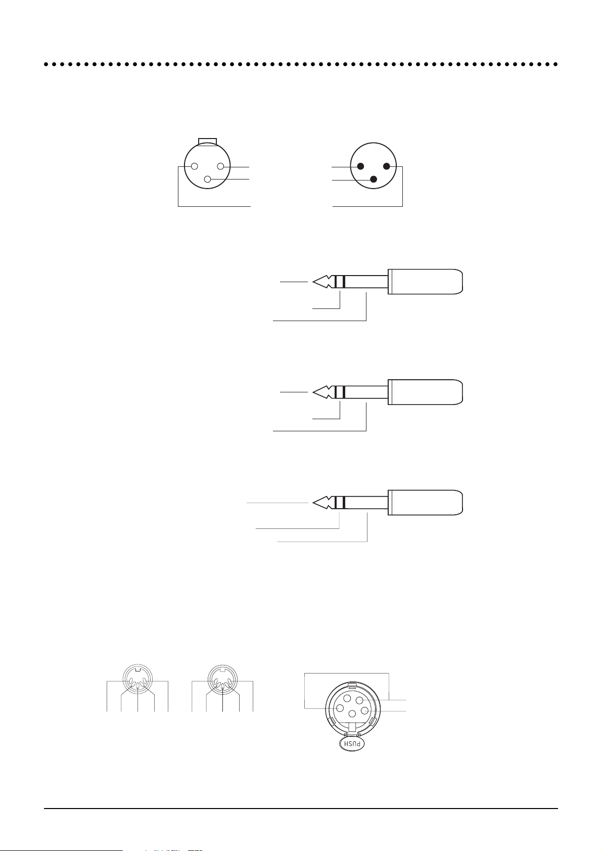
CCoonnnneeccttiioonnss
22
11
33
ALL INPUTS ALL OUTPUTS
GROUND (SCREEN)
COLD (OUT OF
PHASE SIGNAL)
HOT
(IN PHASE SIGNAL)
Socket(female)
Plug(male)
3-pole XLR
Audio Connectors
Lamp Connectors
MIDI Connectors
Tip - HOT(IN PHASE SIGNAL)
Ring - COLD(OUT OF PHASE SIGNAL)
Sleeve - GROUND(SCREEN)
Tip - HOT(IN PHASE SIGNAL)
Ring - COLD(OUT OF PHASE SIGNAL)
Sleeve - GROUND(SCREEN)
1
4/
"
Stereo Jack Plug used as balanced Input/Output:
Tip - LEFT SIGNAL
Ring - RIGHT SIGNAL
Sleeve - GROUND(SCREEN)
Pin4=0V
Pins 1 and 3 = +/-12V
1
4/
"
Stereo Jack Plug used for Inserts
1
4
/"Stereo Jack Plug used for Headphones
Not Used
Midi In -
Midi In +
Not Used
Not Used
1
4
2
5
3
MIDI IN
Not Used
Not Used
GND
MIDI Out -
MIDI Out +
MIDI OUT
1
4
2
5
3
Page 15

SM20 Installation 2.7
JJuummppeerr OOppttiioonnss
IInnppuutt MMoodduullee RRHH BBooaarrdd
J1 Insert Send/Return Fitted = Pre EQ (default)
J2 Insert Send/Return Fitted = Pre EQ (default)
J3 Insert Send/Return Fitted = Pre EQ (default)
J4 Insert Send/Return Fitted = Post EQ
J5 Insert Send/Return Fitted = Post EQ
J6 Insert Send/Return Fitted = Post EQ
J7 Direct Out Fitted = Pre EQ (default)
J8 Direct Out Fitted = Pre Mute
J9 Direct Out Fitted = Post Mute
J10 Direct Out Fitted = Pre EQ, Post Mute
J11 Groups 1-4 Pre Source Fitted = Pre EQ
J12 Groups 1-4 Pre Source Fitted = Pre Mute
J13 Groups 1-4 Pre Source Fitted = Post Mute (default)
J14 Groups 1-4 Pre Source Fitted = Pre EQ/Post Mute
J15 Groups 5-8 Pre Source Fitted = Pre EQ
J16 Groups 5-8 Pre Source Fitted = Pre Mute
J17 Groups 5-8 Pre Source Fitted = Post Mute (default)
J18 Groups 5-8 Pre Source Fitted = Pre EQ/Post Mute
J19 Groups 9-12 Pre Source Fitted = Pre EQ
J20 Groups 9-12 Pre Source Fitted = Pre Mute
J21 Groups 9-12 Pre Source Fitted = Post Mute (default)
J22 Groups 9-12 Pre Source Fitted = Pre EQ/Post Mute
J23 Groups L/R Pre Source Fitted = Pre EQ
J24 Groups L/R Pre Source Fitted = Pre Mute
J25 Groups L/R Pre Source Fitted = Post Mute (default)
J26 Groups L/R Pre Source Fitted = Pre EQ/Post Mute
J27 Direct Out Fitted = Postfade
OOuuttppuutt MMoodduullee
No jumper-selectable options.
MMaasstteerr MMoodduullee CCeennttrree BBooaarrdd
No jumper-selectable options
MMaasstteerr MMoodduullee RRHH BBooaarrdd
J1 Talk to FOH dc signalling 1-2 = disabled
2-3 = enabled (default)
J2 FOH TB In dc signalling 1-2 = enabled (default)
2-3 = disabled
Page 16

2.8 SM20 Installation
Page 17

SM20 Block Diagrams 3.1
SSMM2200
BBlloocckk DDiiaaggrraammss
3
Page 18

3.2 SM20 Block Diagrams
OPTIONAL RELAY
SWITCH TRANSFORMER
BOARD
MULTIPIN
OPTION
INSERT
SEND
INSERT
RETURN
DIRECT
OUTPUT
MULTIPINOPTION
POSTMUTE
POSTMUTE
PRE EQ/POST MUTE
PRE EQ/POST MUTE
PRE EQ/POST MUTE
PRE EQ/POST MUTE
PRE EQ/POST MUTE
PRE EQ/POST MUTE
PRE EQ/POST MUTE
PRE EQ/POST MUTE
POSTFADE
POSTMUTE
POSTMUTE
POSTMUTE
POSTMUTE
POSTMUTE
SEND R
SEND 8B
SEND 7B
SEND 12B
SEND 11B
SEND 10B
SEND 9B
SEND L
SEND 8A
SEND 7A
SEND 6
SEND 5
SEND 12A
PRE
PRE
PRE
GLOBAL STE SWITCHING BUSSES
GLOBAL STE SWITCHING BUSSES
PRE
EQ
PFL
INS
MUTE
SAFE
1
8
MUTE
RNGE
+48V
PRE
PRE
PRE
PRE
PRE
PRE
PRE
PRE
PRE
SEND 11A
SEND 10A
SEND 9A
PREMUTE
PRE_EQ
POST EQ
SHELFSHELF
POSTEQ
PRE_EQ
20-400Hz
+20 PK
+14
+18+5+30-5
-10
-20
-30
INPUT
METER
POST EQ
POSTFADE
PEAK
DETECTOR
HI-PASSFILTER
BELLBELL
FREQFREQ
Q
FREQ
Q
FREQ
CUT/
BOOST
CUT/
BOOST
CUT/
BOOST
CUT/
BOOST
28kHz
28kHz
12kHz
3
12kHz
1.5kHz
3
1.5kHz
480Hz
480Hz
1kHz
1kHz
450Hz
0.5
450Hz
78Hz
0.5
78Hz
LF HFLOW_MID HI_MID
30Hz
30Hz
PFL
LOGIC
PFL DETECT
GLOBAL STE SWITCHING BUSSES
GROUP BUSSES 1-20
PFL BUS
INPUT SOLO CLEAR
SEND 4
SEND 3
SEND 2
SEND 1
L/R
L/R
L/R
L/R
L/R
L/R
L/R
PREMUTE
PREMUTE
PREMUTE
PREMUTE
PREMUTE
PREMUTE
PRE_EQ
PRE_EQ
PRE_EQ
PRE_EQ
PRE_EQ
PRE_EQ
PRE_EQ
POSTED
POSTED
PRE_EQ
MUTE
LOGIC
MUTE BUS
MUTE ASGN
(2 OF 8 SHOWN)
FADER
+10
PREMUTE
PREMUTE
PRE_EQ
POSTFADE
PRE_EQ
POSTFADE
-2dBu GROUND COMP O/P
-2dBu GROUND COMP O/P
-2dBu WITH GROUND COMP SEND
+4dBu WITH EBOS BALANCED SEND
+4dBu BALANCED EBOS
OPTION AVAILABLE
+4dBu BALANCED EBOS
OPTION AVAILABLE
MIC SPLIT
-2dBu TO -70dBu
+10dBu TO -20dBu
INPUT
1
1
2
2
3
3
PIN 1
LIFT
REMOVE LINKS
FOR TX OPTION
+48V
INPUT REAR CONN
SENS
PUSH
Ø
Input Module
Page 19

SM20 Block Diagrams 3.3
OUT
L
R
STE
STE LINKING
AFL TRIM
AFL
OUT
L
R
SUMMING AMP
GRP 7A(1 OF 6 STEREO SENDS)
FADER
+10
INSERT
AFL
LOGIC
STE LINKING
AFL LOGIC OUT
AFL CLEAR
0dB STE MODE
-6dB MONO MODE
+10
-10
0
LOGIC BUS
LOWER MONO GROUP SHOWN
UPPER MONO GROUP 1 OF 2 SHOWN
GROUPS A AND B CAN BE CONFIGURED AS A STEREO
GRP 7A/8 (1 OF 6 SEND ENABLE LINES)
STE
LOGIC
INSERT
-6dB
+10
SUMMING AMP
GRP 1(1OF6)
AFL
LOGIC
AFL
AFL TRIM
AFL LEFT
AFL RIGHT
GROUP BUS A
GROUP BUS L
GROUP BUSSES
AFL LEFT
AFL RIGHT
GROUP BUS A
GROUP BUS L
GROUP BUSSES
0
+10
-10
AFL LOGIC OUT
AFL CLEAR
FADER
GLOBAL MUTE
MUTE
6dB DIM
6dB DIM
MUTE
MUTE
LOGIC
GLOBAL MUTE
OUTPUT TO DIM
OUTPUT TO DIM
TB/OSC BUS
TB/OSC BUS
TB
TB
EBOS
EBOS
EBOS
EBOS
EXT IN
EXT IN
+10
+10
ON
ON
TO OPTIONALVU OVERBRIDGE
TO OPTIONALVU OVERBRIDGE
GROUP OUTPUT AND
GROUP INSERTREAR CONNS
GROUP OUTPUT AND
GROUP INSERTREAR CONNS
(Tx/MULTIPIN)
GROUP
OUTPUT
GROUP
OUTPUT
+20
+20
-20
-20
-30
-30
+15
+15
-15
-15
+10
+10
-10
-10
+5
+5
-5
-5
0
0
INSERT
RETURN
INSERT
RETURN
INSERT
SEND
INSERT
SEND
EXTERNAL
INPUT
EXTERNAL
INPUT
2
2
2
2
1
1
1
1
3
3
3
3
PUSH
PUSH
MUTE
LOGIC
Ø
Ø
å
å
å
å
Output Module
Page 20
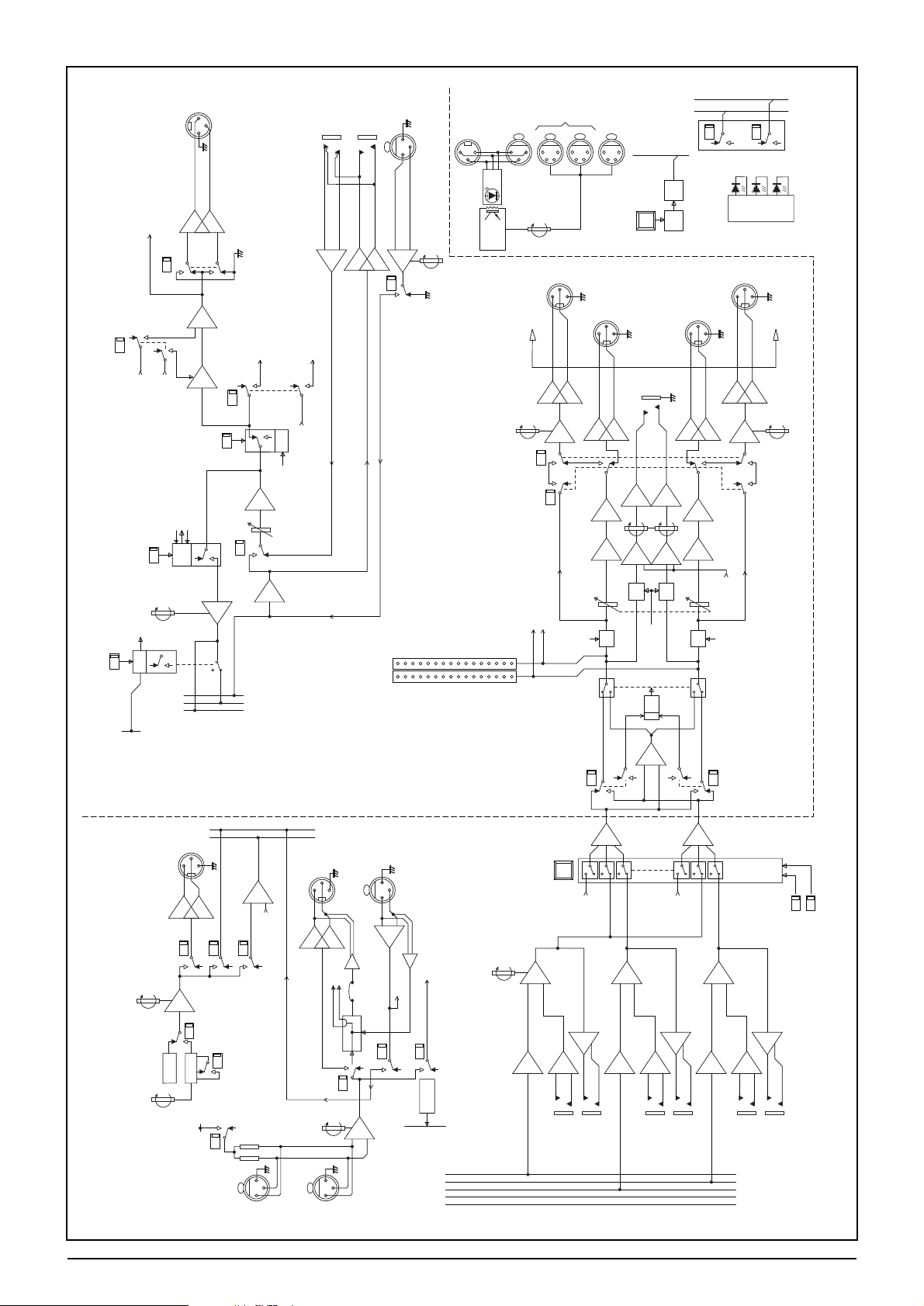
3.4 SM20 Block Diagrams
SUPPLY
RAIL
SENSE
CIRCUITRY
ALT
WEDGE R
OUTPUT
WEDGE R
OUTPUT
DELAY
LOGIC
MUTE
LOGIC
GROUP MUTE
LOGIC BUS
XLR
LOCATED
ON MASTER
XLRS
LOCATED
ON END CHEEKS
MUTE
ALL
GROUPS
WEDGE L
OUTPUT
ALT
WEDGE L
OUTPUT
PHONES
OUTPUT
PHONES
LEVEL
PHONES
DIM
MONO
LOGIC
MONO
SOURCE
MONO
SOURCE
SOLO
CLR
PFLTRIM0
+10
-10
LPOST FADE
R POST FADE
EXT AFL
RIGHT OUT
EXT AFL
LEFT OUT
EXT PFL
OUT
EXT AFL
RIGHT IN
PFLDETECT
AFLDETECT
AFLLEFT BUS
AFLRIGHT BUS
PFLBUS
EXT AFL
LEFT IN
EXT PFL
IN
I/P PRIORITY
AUTO CANCEL
ENBL
ENBL
SOLO
LOGIC
L
R
&
EXT TB TOPHONES
FADER
FADER
WEDGE DIM
WEDGE DIM
TO OPTIONALVU OVERBRIDGE
TO OPTIONALVU OVERBRIDGE
DIM
20dB
DIM
15dB
DIM
15dB
DIM
20dB
ALT
WEDGE
LEVEL
LAMP
DIMMER
IN
CALL
DETECT
EXTERNAL
INPUT
INSERT
SEND
INSERT
RETURN
GROUP
OUTPUT
1
2
3
EBOS
ON
+10
L/R TO WEDGE
LPOST FADE
R POST FADE
R POST MUTE
MUTE
LOGIC
+10
FADER
INSERT
AFL
LOGIC
STE
LOGIC
OSCILLATOR
OUTPUT
TB/OSC
ON
ON
ON
+10
OSC
LEVEL
FREQ
TB
GAIN
63Hz
-20
FOH
ON
ON
TALKTO
TALKTO
BUSSES
(TB/OSC)
TALKTO
OUTPUTS
(TB/OSC)
TB/OSC
15V CARRIER DETECT
EXT TB TOPHONES
15V
CARRIER ENABLE
WEDGE DIM
PHONES DIM
OUTPUT
TB/OSC DIM
LOGIC BUS
GROUP OUTPUTDIM
TB/OSC BUS
GROUP BUSSES
TALKBACK
LOGIC
1kHz
-50
x10
SRC
OSCILLATOR
TB MIC
ON REAR
FOH TALKBACK
OUTPUT
FOH TALKBACK
INPUT
1
1
1
1
2
2
2
3
3
3
2
3
TB MIC
ON MASTER
PUSH
PUSH
PUSH
PUSH PUSH PUSH
PUSH
PUSH
48V
+48V
PINK NOISE
GENERATOR
OSC TO
OUTPUTS
(TB/OSC)
OSC TO
ALLBUSSES
OSC TO
XLR O/P
1
2
3
STEREO SEND ENABLE
GRP L/R
STE LINKING
LOGIC BUS
STE LINKING
AFLLOGIC OUT
AFLCLEAR
AFL
AFLLEFT
AFLRIGHT
GROUP BUSSES L/R
STE
GRP L
AFLTRIM0
+10
-10
SUMMING
AMP
0dB STE MODE
-6dB MONO MODE
OUT
GLOBALMUTE
ON
MUTE
EBOS
TO OPTIONALVU OVERBRIDGE
TB/OSC BUS
TB
OUTPUT TB DIM
6dB DIM
EXT IN
LITTLITE
BLINK
OSCILLATOR
OUT
CLEAR COM
ALT
WEDGE
LEVEL
ALT
WEDGE
ALT
WEDGE
WEDGE
MONO GROUP 1 OF 2 SHOWN
GROUPS A AND B CAN BE CONFIGURED AS A STEREO PAIR
+20+20
+15+15
+10+10
+5+500-5-5
-10-10
-15
-20
-30
-15
-20
-30
R L
PRE
ON
+10
+10
+10
+10
1
1
1
1
1
1
1
2
2
2
2
2
2
2
3
3
3
3
3
3
3
MUTE MASTERS
MUTE BUS
1
8
+5V
±17V
+48V
Ø
å
å
å
å
å
å
å
å
å
å
å
å
å
å
GROUP OUTPUT AND
GROUP INSERTREAR CONNS
(Tx/MULTIPIN)
Master Module
Page 21

SM20 Functional Description 4.1
SSMM2200
FFuunnccttiioonnaall DDeessccrriippttiioonn
4
Page 22

4.2 SM20 Functional Description
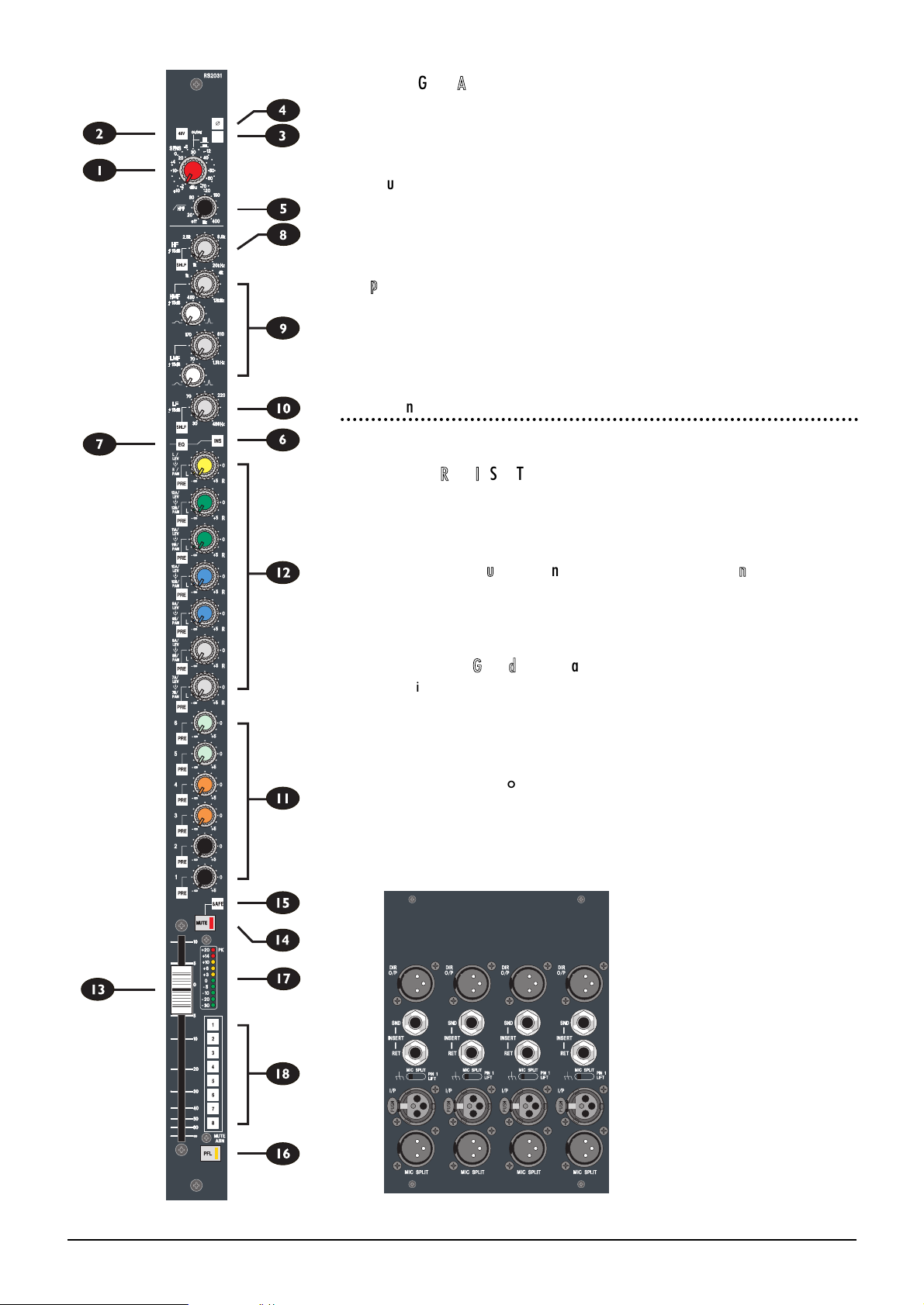
IInnppuutt MMoodduullee
1
SSEENNSS ((SSeennssiittiivviittyy))
The SENSitivity Control adjusts the level of the signal which is present on the
Input XLR. The input can handle mic or line level signals up to +30dBu, with the
RANGE switch (see below) selecting high or low sensitivity.
2
4488VV
The 48V switch, when it is depressed, places 48V phantom power on pins 2 & 3 of
the input XLR. An integral LED glows when the phantom power is on.
3
RRNNGGEE ((RRaannggee))
The RNGE (Range) switch selects between an input range of -2dBu to -70dBu
(switch released), and +10dBu to -20dBu (switch pressed and lit), enabling both
mic and line level signals to be handled by a common input stage.
CAUTION: Phantom power should not be switched on when unbalanced sources
are connected to the XLR input.
4
ØØ ((PPhhaassee))
The PHASE switch reverses the phase of the input signal, to compensate for
incorrect wiring or mic placement. The switch is internally illuminated when phase
is reversed.
5
HHPPFF ((HHiigghhppaassss FFiilltteerr))
The HPF Filter control sets the cutoff (-3dB) frequency of the high-pass filter: it is
adjustable between 20Hz and 400Hz, to help reduce stage rumble or popping
from microphones. The control also has a built-in switch to switch the filter out of
circuit when rotated fully anticlockwise.
6
IINNSS ((IInnsseerrtt PPooiinntt))
The Insert Point may be switched in circuit by the INS switch. The insert uses
separate balanced jacks for send and return. It is normally positioned after the
filter and before the equaliser, but can be repositioned using internal jumpers to
be post-EQ if required. The insert is in-circuit when the switch is illuminated.
7
EEQQ
The EQ section comprises four sweepable bands, and the two mid bands are fully
parametric, with adjustable Q. The EQ is enabled when the EQ switch is pressed,
and bypassed when the switch is released. The EQ is active when the EQ switch
is illuminated.
8
HHFF
The HF section is fully sweepable, providing 15dB boost or cut at 1kHz to 20kHz.
The section can be switched to work as either a Shelving control (SHLF switch
pressed) or Bell control (switch released).
9
HHMMFF//LLMMFF
The high and low MID sections comprise a dual concentric control to set the
centre frequency (outer ring) and 15dB of boost or cut (upper knob). The HMF
spans the range 450Hz to 12kHz and the LMF spans the range 70Hz to 1.5kHz.
Each section has an associated Q control, variable from 0.5 to 3.0.
0
LLFF
The LF section is fully sweepable, providing 15dB boost or cut at 30Hz to 480Hz.
The section can be switched to work as either a Shelving control (SHLF switch
pressed) or Bell control (switch released).
RNGE
Page 23

SM20 Functional Description 4.3
q
MMoonniittoorr SSeennddss 11--66
Sends are provided to the 20 output busses, and are designed to allow a mixture
of mono and stereo sends that will suit typical operational scenarios. The lower 6
sends are configured as full-time mono sends, using single pots. Pressing the PRE
button adjacent to each Send switches the source to pre-fade. The outputs of
these mixes are controlled by the lower bank of 6 output faders in the output
section. The pre-fade source for the sends may be reconfigured to suit individual
requirements - see Jumper options in Chapter 2.
w
MMoonniittoorr SSeennddss 77--1122,, LL//RR
The sends to outputs 7-20 are on dual concentric pots, and each row can be
configured at the touch of a button as either a stereo send with level on the top
knob and pan on the lower, or a pair of mono sends. These mixes are controlled
by the upper bank of 12 faders in the output section, and are labelled 7A and B to
12A and B. Stereo mode is selected by pressing the Global Mode STE button on
the respective output module.
The last pair of sends although marked L and R, is functionally identical to the
other stereo sends and can either be used as a stereo sidefill output, or two mono
sends. The output faders for these sends are located on the master module.
The pre-fade feed for all sends is jumper selectable in four groups, pre or post-EQ
and pre or post-mute, allowing the module to be configured with any combination
of between 20 mono and 6 mono plus 7 stereo sends. The pre-fade source for
the sends may be reconfigured to suit individual requirements - see Jumper
options in Chapter 2.
e
FFaaddeerr
A high-quality 100mm channel fader controls the level to all busses, and has 10dB
of gain when full up as well as an expanded scale around the critical unity gain area,
for maximum resolution.
Rr
MMUUTTEE
The Channel MUTE switch mutes all feeds from the input channel, and can be
remotely controlled by the consoles Mute Master section, allowing creation of up
to 8 mute groups. The integral LED illuminates when the Mute is active.
t
SSAAFFEE
A semi-recessed Mute SAFE switch allows the channel to be prevented from
remote muting by mute groups, but still allows it to be locally muted. Safe mode
is selected when the switch is pressed and internally illuminated.
y
PPFFLL
The PFL button is conveniently located below the fader, and provides a mono PFL
or stereo AFL feed to the engineers wedge output and headphones. Intercancel
or additive soloing is possible, with or without Input Priority, and solos can be
cleared with a single button press (SOLO CLEAR) at the master section.
The integral LED illuminates to indicate that a PFL is active.
u
LLEEDD iinnppuutt mmeetteerriinngg
The channel is fitted with a 10-segment peak-reading bargraph meter, positioned
next to each fader for maximum visibility and giving immediate and graphic
indication of incoming (pre-EQ) signals. The top (red) LED in the bar is configured
as a Peak LED, and monitors the signal path in three places, (pre-EQ, post-EQ and
post-fader) giving warning that the signal is within 3dB of clipping.
RNGE
Page 24
4.4 SM20 Functional Description
iI
MMuuttee GGrroouupp AAssssiiggnnmmeenntt
Each input channel can be assigned to any combination of 8 mute groups, using the
recessed switch bank next to the fader. The corresponding mute master buttons
are located on the master module.
DDiirreecctt OOuuttppuutt
A balanced direct output is available on a male XLR on the rear panel. This is fed
from a pre-fade signal which can be jumper selectable to be pre or post-EQ, and
pre or post-mute, or may be jumper-selected as post-fade.
MMiicc SSpplliitt
A passive mic split output is available on a male XLR on the rear panel, for
feeding input signals to the FHO console in applications where a separate stage
splitter is not available. A pin 1 lift switch allows the pin 1 of this XLR to be
disconnected console chassis ground.
RReeaarrccoonn PPaanneell
The connections on the rearcon panel are as follows:
IINNPPUUTT XXLLRR && MMIICC SSPPLLIITT
Pin 1 Gnd (Screen)
Pin 2 Hot (In-phase signal)
Pin 3 Cold(Out-of-phase signal)
DDIIRREECCTT OOUUTT ((GGrroouunndd CCoommppeennssaatteedd)) ((BBaallaanncceedd ooppttiioonn))
Pin 1 Gnd (Screen) Gnd (Screen)
Pin 2 Signal Hot (In-phase signal)
Pin 3 Ground Sense Cold(Out-of-phase signal)
IINNSSEERRTT SSEENNDD ((GGrroouunndd CCoommppeennssaatteedd)) ((BBaallaanncceedd ooppttiioonn))
Tip Signal Hot (In-phase signal)
Ring Ground Sense Cold (Out-of-phase signal)
Sleeve Gnd (Screen) Gnd(screen)
IINNSSEERRTT RREETTUURRNN
Tip Hot (In-phase signal)
Ring Cold (Out-of-phase signal)
Sleeve Gnd(screen)
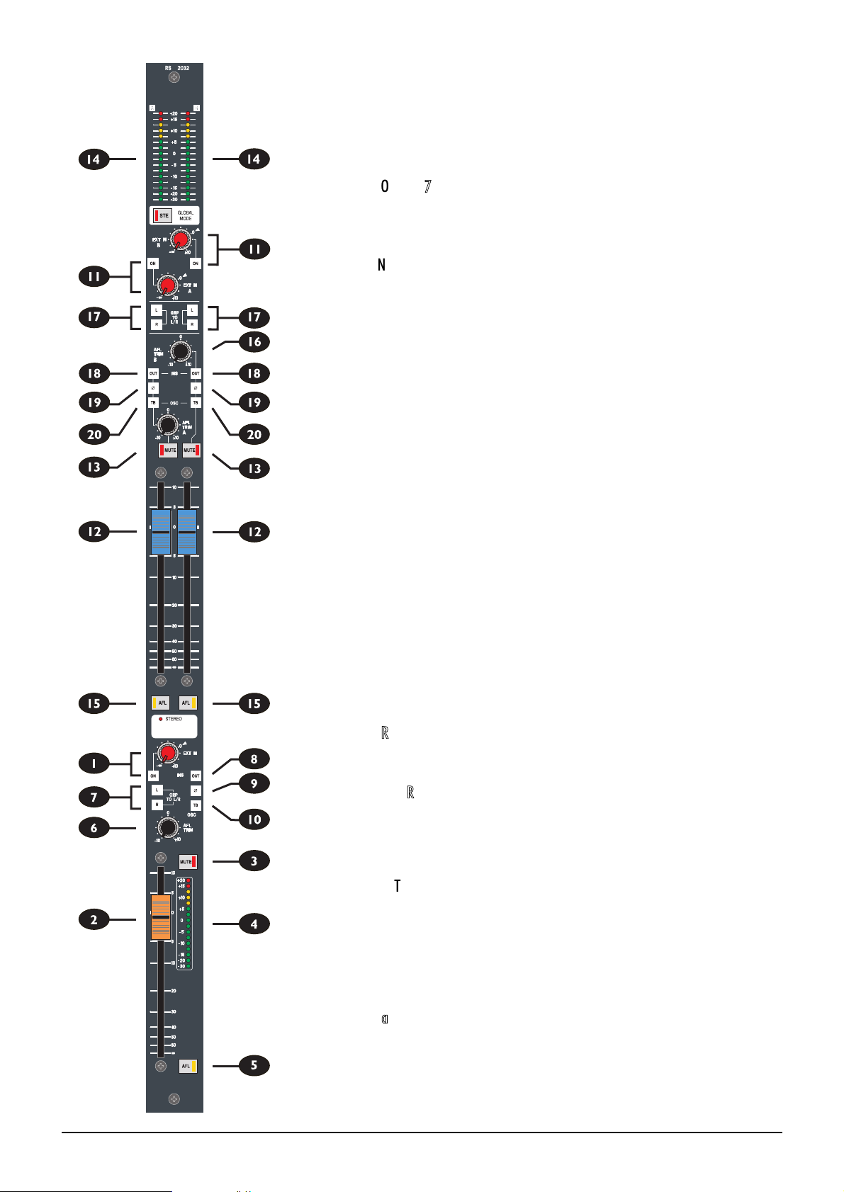
OOuuttppuutt MMoodduullee
RNGE
Page 25

SM20 Functional Description 4.5
Each of the six Output Modules has two sections: The lower sections are
dedicated mono outputs, and the top sections are arranged as 6 pairs of controls
with a Global Mode switch which allows each pair to be configured as two monos
or one stereo output.
MMoonnoo OOuuttppuuttss 11--66
1
EEXXTT IINN
The EXT IN level control adjusts the level of an external input which can be
brought in via the balanced XLR for summing to the Output bus. The input is
enabled when the associated ON switch is pressed.
2
FFAADDEERR
The 100mm fader controls the final level to the electronically balanced output.
3
MMUUTTEE
The output is muted when the switch is pressed, and the integral LED illuminates
to show that the MUTE is active.
4
MMEETTEERR
A peak-reading 16-segment LED Bargraph Meter displays the level of the output
after the Talkback/Oscillator injection point. An optional VU meterbridge may
also be fitted.
5
AAFFLL
The AFL (After-Fade Listen) source is after the insert point. The AFL signal is
switched through to both AFL L and AFL R buses by the AFL switch. An integral
LED glows when AFL is active. The AFL may be switched off by pressing the AFL
switch again, or by the Solo Logic system which is controlled from the Master
Module.
6
AAFFLL TTRRIIMM
AFL TRIM adjusts the level of the AFL signal by +/-10dB.
7
GGRRPP TTOO LL//RR
The internally illuminated L and R switches route the post-mute, post-fade output
signal to the last pair of output busses (designated L and R) for subgrouping,
allowing the SM20 to be used as a Front-of-House mixer if necessary.
8
IINNSS ((OOUUTT))
The Insert Point consists of separate Send and Return jacks on the rear panel. The
Send is normalled to the Return.
The OUT switch bypasses the Insert Point when pressed, but leaves the pre-fade
output signal on the Send jack to feed external equipment if required. The switch
is illuminated when the insert is bypassed.
9
ØØ ((PPhhaassee))
Pressing the Ø (Phase) switch reverses the phase of the output, to allow
experimentation for best feedback immunity with a multiple-mic setup. The
switch is illuminated when the phase is reversed.
0
OOSSCC//TTBB
Pressing this latching switch arms the output to receive talkback, tone or pink
Page 26
4.6 SM20 Functional Description
noise from the central talkback/oscillator section on the Master, when either the
master TALK TO OUTPUTS or OSC TO OUTPUTS switches are active. The
switch illuminates to warn the the OSC/TB is armed. The output is dimmed by
6dB when talkback is active. Alternatively, if the Master Talkback or Oscillator
signal is already active, pressing OSC/TB switch routes the Talkback or Oscillator
signal to the output, until the switch is released.
MMoonnoo//SStteerreeoo OOuuttppuuttss 77--1122
These outputs may either be configured as mono sends or as stereo pairs by
pressing the Global Mode (STE) switch (see
a
below).
q
EEXXTT IINN
The EXT IN level control adjusts the level of an external input which can be
brought in via the balanced XLR for summing to the Output bus. The input is
enabled when the associated ON switch is pressed.
w
FFAADDEERR
The 100mm fader controls the final level to the electronically balanced output.
e
MMUUTTEE
The output is muted when the switch is pressed, and the integral LED illuminates
to show that the MUTE is active.
r
MMEETTEERR
A peak-reading 16-segment LED Bargraph Meter displays the level of the output
after the Talkback/Oscillator injection point. An optional VU meterbridge may
also be fitted.
t
AAFFLL
The AFL (After-Fade Listen) source is after the insert point. The AFL signal is
switched through to both AFL L and AFL R buses by the AFL switch. An integral
LED glows when AFL is active. The AFL may be switched off by pressing the AFL
switch again, or by the Solo Logic system which is controlled from the Master
Module. In stereo mode the Solo switches are logic linked to give automatic stereo
AFL.
y
AAFFLL TTRRIIMM
AFL TRIM adjusts the level of the AFL signal by +/-10dB.
u
GGRRPP TTOO LL//RR
The L and R switches route the post-mute, post-fade output signal to the last pair
of output busses (designated L and R) for subgrouping, allowing the SM20 to be
used as a Front-of-House mixer if necessary.
i
IINNSS ((OOUUTT))
The Insert Point consists of separate Send and Return jacks on the rear panel. The
Send is normalled to the Return.
The OUT switch bypasses the Insert Point when pressed, but leaves the pre-fade
output signal on the Send jack to feed external equipment if required. The switch
is illuminated when the insert is bypassed.
o
ØØ ((PPhhaassee))
Pressing the Ø (Phase) switch reverses the phase of the output, to allow
experimentation for best feedback immunity with a multiple-mic setup. The
Page 27

SM20 Functional Description 4.7
switch is illuminated when the phase is reversed.
p
OOSSCC//TTBB
Momentarily pressing this switch arms the output to receive talkback, tone or pink
noise from the central talkback/oscillator section on the Master, when either the
master TALK TO OUTPUTS or OSC TO OUTPUTS switches are pressed. The
switch illuminates to warn that OSC/TB is armed. The output is dimmed by 6dB
when talkback is active. Alternatively, if the Master Talkback or Oscillator signal is
already active, pressing and holding the switch for more than about one second
routes the Talkback or Oscillator signal momentarily to the output, until the
switch is released.
a
GGLLOOBBAALL MMOODDEE ((SSTTEE))
When STE is pressed the two upper outputs become a stereo pair. In this mode
the dual concentric sends on the input channels are automatically configured as a
stereo Level on top and Pan on the bottom, instead of two separate mono sends,
and the AFL buttons are linked. The integral LED illuminates to show when Stereo
mode is active.
RReeaarrccoonn PPaanneellss
The connections on the rearcon panes are as follows:
OOUUTTPPUUTT XXLLRR ,, EEXXTT II//PP ((oonn MMaasstteerr RReeaarrccoonn PPaanneell -- sseeee MMaasstteerr SSeeccttiioonn))
Pin 1 Gnd (Screen)
Pin 2 Hot (In-phase signal)
Pin 3 Cold(Out-of-phase signal)
IINNSSEERRTT SSEENNDD && RREETTUURRNN
Tip Hot (In-phase signal)
Ring Cold (Out-of-phase signal)
Sleeve Gnd(screen)
Page 28

4.8 SM20 Functional Description
MMaasstteerr MMoodduullee
LL && RR OOuuttppuuttss
1
EEXXTT IINN
The EXT IN level control adjusts the level of an external input which can
be brought in via the balanced XLR for summing to the Output bus. The
input is enabled when the associated ON switch is pressed.
2
FFAADDEERR
The 100mm fader controls the level to the electronically balanced output.
3
MMUUTTEE
The output is muted when the switch is pressed, and the integral LED
illuminates to show that the MUTE is active.
4
MMEETTEERRSS
Peak-reading 16-segment LED Bargraph Meters display the level of the
Wedge output signal, which is normally PFL/AFL. However, when the L/R
TO WEDGE switch is ON, the Wedge output receives the L/R output
signal, and this will be displayed on these meters, although this selection is
always overridden by an active AFL/PFL. Note that if the optional VU
meterbridge is fitted, separate L/R.output meters are included.
5
AAFFLL
The AFL (After-Fade Listen) source is after the insert point. The AFL signal
is switched through to both AFL L and AFL R buses by the AFL switch. An
integral LED glows when AFL is active. The AFL may be switched off by
pressing the AFL switch again, or by the Solo Logic system which is
controlled from the Master Module. In stereo mode the Solo switches are
logic linked to give automatic stereo AFL.
6
AAFFLL TTRRIIMM
AFL TRIM adjusts the level of the AFL signal by +/-10dB.
7
IINNSS ((OOUUTT))
The Insert Point consists of separate Send and Return jacks on the rear
panel. The Send is normalled to the Return.
The OUT switch bypasses the Insert Point when pressed, but leaves the
pre-fade output signal on the Send jack to feed external equipment if
required. The switch is illuminated when the insert is bypassed.
8
ØØ ((PPhhaassee))
Pressing the Ø (Phase) switch reverses the phase of the output, to allow
experimentation for best feedback immunity with a multiple-mic setup.
The switch is illuminated when the phase is reversed.
9
OOSSCC//TTBB
Pressing this latching switch arms the output to receive talkback, tone or
pink noise from the central talkback/oscillator section on the Master, when
either the master TALK TO OUTPUTS or OSC TO OUTPUTS switches
are active. The switch illuminates to warn the the OSC/TB is armed. The
output is dimmed by 6dB when talkback is active. Alternatively, if the
Master Talkback or Oscillator signal is already active, pressing OSC/TB
switch routes the Talkback or Oscillator signal to the output, until the
switch is released.
Page 29

SM20 Functional Description 4.9
0
GGLLOOBBAALL MMOODDEE ((SSTTEE))
When STE is pressed the two upper outputs become a stereo pair. In this mode
the dual concentric sends on the input channels are automatically configured as a
stereo level on top and pan on the bottom, instead of two separate mono sends.
The integral LED illuminates to show when Stereo mode is active.
WWeeddggee MMoonniittoorr SSeeccttiioonn
q
WWEEDDGGEE FFAADDEERR
A stereo 100mm fader is provided for engineers Wedge speakers, and this
normally receives any PFL or AFL signals when an input or output SOLO button is
pressed. When no solos are selected, the Wedge output is normally silent, unless
the L/R to Wedge switch is pressed (see
r
below), in which case the L/R
outputs are heard, or an external AFL/PFL is present.
w
MMOONNOO SSOOUURRCCEE LL && RR
Mono source buttons L and R allow either the Left or Right monitor/solo signals to
be fed to both left and right wedge outputs, or if both are pressed, a mono sum of
left and right monitor/solo signals is fed to both left and right wedge outputs. The
switches illuminate when active.
e
AALLTT WWEEDDGGEE
An Alternate Wedge stereo output is provided, with its own level control.
Pressing the internally illuminated ON switch enables the Alternate Wedge output
and mutes the main wedge, allowing monitoring on either one or another type of
speaker. (for example a standard wedge or an in-ear radio system).
The Alt Wedge is normally sourced post the main wedge fader, but may be
switched to pre-fade by pressing the associated PRE switch.
r
LL//RR TTOO WWEEDDGGEE
The Wedge speakers normally receive any PFL or AFL signals when an input or
output SOLO button is pressed. When no solos are selected, the Wedge output is
normally silent, unless the L/R TO WEDGE switch is pressed (in which case the
L/R outputs are heard) or an external AFL/PFL is present. The switch illuminates
when ON.
t
PPHHOONNEESS
The operators phones are fed by the same signal as the Wedge, but have a
separate phones volume control.
The headphone socket is recessed into the front of the master fascia, and is driven
by a high-power (350mW into 8ohms) headphone amp.
Return talkback from another Soundcraft console is automatically switched onto
the headphones, dimming the programme signal.
y
LLAAMMPP DDIIMMMMEERR
The Lamp Dimmer controls the voltage to the 4-pin XLR socket which is provided
for the connection of Littlites.
The pinout is as follows:
Pin 1 & 3 +/-12V
Pin 4 0v
max. current 400mA
u
PPSSUU RRAAIILLSS
Three LEDs monitor the status of the power supply rails.
Page 30

4.10 SM20 Functional Description
TTaallkkbbaacckk aanndd OOsscciillllaattoorr SSeeccttiioonn
The talkback and oscillator sections have similar routing systems, allowing
them to access any of the console busses. The talkback section has front and
rear panel mic input XLRs, with phantom power capability. The mic signal can
be routed either to selected internal busses, or sent to a Soundcraft
proprietary intercom output (compatible with Series FIVE or another SM
monitor console).
i
TTAALLKKBBAACCKK MMIICC
Talkback Mic input XLRs are provided on the front and rear panel, with 48V
phantom power capability when the 48V switch is pressed.
o
LLEEVVEELL
This control adjusts the gain of the Talkback Mic preamp over a 30dB range.
p
FFOOHH TTOO BBUUSSSSEESS
The FOH TO BUSSES (ON) switch allows any return talkback from the FOH
console to be routed directly to the monitor outputs via the TB/Osc buttons,
for use when the monitor engineer has to leave the console unattended during
setup or soundcheck. The FOH talkback is enabled when the switch is
illuminated.
a
TTAALLKK TTOO FFOOHH
TALK TO FOH routes the talkback signal to the proprietary Soundcraft
intercom output (compatible with Series FIVE or another SM monitor console)
on the rear panel. When TALK TO FOH is active (LED illuminated) the FOH
TB OUT XLR on the rear panel carries the talkback signal plus a nominal 15V
DC superimposed on it to page the FOH console. The DC voltage may be
disabled by internal jumpers if required.
s
TTAALLKK TTOO OOUUTTPPUUTTSS ((TTBB//OOSSCC))
TALK TO OUTPUTS (TB/OSC) routes the talkback signal to any outputs
which have been previously armed for talkback (local TB switch ON). If the
switch is pressed momentarily, the switch latches. Alternatively, pressing and
holding the switch for more than about one second produces a momentary
action until the switch is released. The switch illuminates to warn that TB/OSC
is active.
OOSSCCIILLLLAATTOORR
The oscillator generates either tone or pink noise, and has its own
independent balanced XLR output on the rear panel. The oscillator can be
routed either individually to outputs, or to all busses simultaneously.
d
LLEEVVEELL
This control adjusts the oscillator level to both the XLR output and the internal
busses.
f
SSRRCC ((SSoouurrccee))
The oscillator generates either TONE (switch pressed and illuminated) from
63Hz to 10kHz, or pink noise (switch released).
g
xx1100
The normal frequency range of the oscillator is 63Hz to 1kHz. Pressing the
x10 switch (internal LED lit)provides a higher range of 630Hz to 10kHz.
Page 31

SM20 Functional Description 4.11
h
OOSSCC TTOO XXLLRR OO//PP
The rear panel OSC OUT XLR is enabled when this switch is pressed. The
internal illumination indicates when the output is active.
j
OOSSCC TTOO AALLLL BBUUSSSSEESS
The Oscillator may be routed directly to all busses simultaneously by pressing the
OSC TO ALL BUSSES switch ON (switch illuminated) where it mixes with any
existing signal.
k
OOSSCC TTOO OOUUTTPPUUTTSS ((TTBB//OOSSCC))
OSC TO OUTPUTS (TB/OSC) routes the oscillator signal to any outputs which
have been previously armed for talkback or oscillator (local TB switch ON). If the
switch is pressed momentarily, the switch latches. Alternatively, pressing and
holding the switch for more than about one second produces a momentary action
until the switch is released. The switch illuminates to warn that TB/OSC is active..
l
PPFFLL TTRRIIMM
The PFL trim control gives +/-10dB of level adjustment to the input solo level
heard in the Wedge and Phones outputs. The output AFL solos have their own
individual trim controls on their respective output modules.
;
IINNPPUUTT PPRRIIOORRIITTYY
The INPUT PRIORITY (ON) switch, when selected, allows an input solo (PFL) to
temporarily override any output solo (AFL) which may be present. When the input
solo is released, the original output solo will reappear on the monitors. If
AUTOCANCEL (see below) is also ON, input PFLs still have priority, but PFLs
will only cancel other PFLs, and AFLs will only cancel other AFLs.
z
AAUUTTOO CCAANNCCEELL
The AUTOCANCEL (ON) button, when selected, allows any solo button selected
to cancel the previous solo. When this mode is not selected, solos can be selected
additively.
x
SSOOLLOO CCLLEEAARR
Pressing SOLO CLEAR cancels any solos on the console.
MMuuttee MMaasstteerrss
c
MMUUTTEE AALLLL OO//PPSS
The MUTE ALL O/Ps button allows total muting of all stage feeds. As protection
against accidental operation, this button has to be held down for 2 seconds before
it will activate. Inputs are not muted (Direct Outs will still be active), and soloing
to the wedge outputs can still take place. The outputs are restored when the
switch is released.
v
MMUUTTEE MMAASSTTEERRSS
8 recessed latching buttons control the mute status of any channels assigned to the
appropriate mute group.
Inputs may be assigned to any combination of the eight master mute busses.
When an input channel is assigned to a mute bus, it is muted when the
corresponding MUTE MASTER is pressed. The MUTE MASTER illuminates and
the input channel MUTE switch also illuminates to indicate that a non-local mute is
active.
Page 32

4.12 SM20 Functional Description
CCoommmmss LLiinnkk
The Comms Link is designed to pick up the call signal from a Clear-Com
intercom and use this to flash the consoles Littlites in order to attract the
engineers attention. There is no connection to the Clear-Com audio,
which passes through unaffected.
The Comms Link will only operate if both the +30V Intercom supply and the
DC Call signal (+4Vdc to +11Vdc) are present on the Comms Link XLRs.
The Comms Link will also operate with the TW option on the Clear-Com
system where a second audio channel is superimposed on the +30Vdc.
OOppttiioonnaall VVUU MMeetteerrbbrriiddggee
An optional VU meterbridge can be installed and contains 22 VU meters for
metering of the 20 main outputs plus an additional pair of meters dedicated to
the Wedge output, which will meter any soloed signal on the console. All VU
meters are illuminated using LED backlighting, and each meter incorporates a
large peak LED which illuminates when the output is within 6dB of clipping.
BBSSSS VVaarriiccuurrvvee RReemmoottee CCoonnttrrooll
A unique feature on the SM20 allows the output solo buttons (in Autocancel
mode) on the console to automatically select the correct EQ page on the
FPC-900 Varicurve Remote Unit, using proprietary MIDI control. This saves
the engineer vital seconds as it avoids the need to solo the output and then
press the appropriate page button on the remote unit.
Note that this function requires the Varicurve remote to be fitted with
operating system EPROM V1.16 or above; contact BSS for further
information.
Page 33

SM20 Functional Description 4.13
RReeaarrccoonn PPaanneell
The connections on the Master rear connector panel are as follows:
AAllll AAuuddiioo XXLLRRss
Pin 1 Gnd (Screen)
Pin 2 Hot (In-phase signal)
Pin 3 Cold(Out-of-phase signal)
CClleeaarr--CCoomm CCoonnnneeccttiioonn ((XXLLRR))
Pin 1 Common (DC ground & Intercom Low)
Pin 2 +30Vdc from Intercom System
Pin 3 Intercom Line (Audio & DC Call Signal)
AAFFLL//PPFFLL OOuutt
Tip Signal
Ring Ground Sense
Sleeve Gnd (Screen)
AAFFLL//PPFFLL BBuuss IInn
Tip Hot (In-phase signal)
Ring Cold (Out-of-phase signal)
Sleeve Gnd(screen)
Page 34

4.14 SM20 Functional Description
Page 35

SM20 Specifications 5.1
SSMM2200
SSppeecciiffiiccaattiioonnss
5
Page 36

5.2 SM20 Specifications
SSMM2200 PPrroovviissiioonnaall SSppeecciiffiiccaattiioonnss
FFrreeqquueennccyy RReessppoonnssee
Any Input to any output 20Hz - 20kHz, +0/-0.5dB
TToottaall HHaarrmmoonniicc DDiissttoorrttiioonn
All measurements at 20dBu
Line In to Group or Mix Out Less than 0.005% @1kHz
Less than 0.025% @10kHz
NNooiissee
22Hz - 22kHz bandwidth, unweighted
Mic input Equivalent Input Noise Less than -127.5dBu (200Ω source)
Group Output Noise Less than -80dBu (40 ch routed)
Mix Output Noise Less than -80dBu (40 ch routed)
CCrroossssttaallkk
All measurements at 1kHz
Input Channel Muting Greater than 100dB
Input Channel Send Pot Isolation Greater than 75dB
Group Fader Isolation Greater than 95dB
Group to Group Crosstalk Less than -75dB
Group to Mix Crosstalk Less than -75dB
Mix to Group Crosstalk Less than -75dB
IInnppuutt aanndd OOuuttppuutt IImmppeeddaanncceess
Input 2kΩ balanced
All Insert Sends Less than 75Ω balanced
All Insert Returns Greater than 10kΩ balanced
Outputs Less than 75Ω balanced
IInnppuutt//OOuuttppuutt CCaappaabbiilliittyy
Maximum Input Level +30dBu
Input Insert Sends +20dBu into 2kΩ (Bal. +26dBu into 1kΩ)
Output Insert Sends +26dBu into 1kΩ
All Insert Returns +26dBu
All Balanced Outputs +26dBu into 1kΩ
Headphone Output +20dBu into 600Ω
+350mW into 8Ω
IInnppuutt aanndd OOuuttppuutt LLeevveellss
Input Sensitivity (XLR) -2dBu to -70dBu, +10dBu to -20dBu
Input Insert Send/Return -2dBu nominal
Output Insert Send/Return +4dBu nominal
Outputs +4dBu for 0VU
PFL/AFL -2dBu nominal
Oscillator +4dBu nominal
 Loading...