


Multi Channel
AV Receiver
Operating Instructions
STR-DN1080
For the customers in the USA
Owner’s Record
The model and serial numbers are located on
the rear of the receiver. Record the serial
number in the space provided below. Refer to
these numbers whenever you call upon your
Sony dealer regarding this product.
Model No. ST R- DN 10 80
Serial No.
WARNING
To reduce the risk of fire or electric shock,
do not expose this apparatus to rain or
moisture.
To reduce the risk of fire, do not cover the
ventilation opening of the appliance with
newspapers, tablecloths, curtains, etc.
Do not expose the appliance to naked flame
sources (for example, lighted candles).
To reduce the risk of fire or electric shock, d o not
expose this appliance to dripping or splashing,
and do not place objects filled with liquids, such
as vases, on the appliance.
Do not install the appliance in a confined space,
such as a bookcase or built-in cabinet.
Do not expose batteries or appliances with
battery-installed to excessive heat, such as
sunshine and fire.
As the main plug is used to disconnect the unit
from the mains, connect the unit to an easily
accessible AC outlet. Should you notice an
abnormality in the unit, disconnect the main
plug from the AC outlet immediately.
The unit is not disconnected from the mains as
long as it is connected to the AC outlet, even if
the unit itself has been turned off.
This symbol is intended to al ert the
user to the presence of the Hot
Surface that may be hot if it is
touched during the normal
operation.
FOR UNITED STATES CUSTOMERS. NOT
APPLICABLE IN CANADA, INCLUDING IN
THE PROVINCE OF QUEBEC.
POUR LES CONSOMMATEURS AUX
ÉTATS-UNIS. NON APPLICABLE AU
CANADA, Y COMPRIS LA PROVINCE DE
QUÉBEC.
For the customers in the USA
This symbol is intended to alert the
user to the presence of uninsulated
“dangerous voltage” within the
product’s enclosure that may be of
sufficient magnitude to constitute a
risk of electric shock to persons.
This symbol is intended to alert the
user to the presence of important
operating and maintenance
(servicing) instructions in the
literature accompanying the
appliance.
Important Safety Instructions
1) Read these instructions.
2) Keep these instructions.
3) Heed all warnings.
4) Follow all instructions.
5) Do not use this apparatus near water.
6) Clean only with dry cloth.
7) Do not block any ventilation openings. Install
in accordance with the manufacturer’s
instructions.
8) Do not install near any heat sources such as
radiators, heat registers, stoves, or other
apparatus (including amplifiers) that produce
heat.
9) Do not defeat the safety purpose of the
polarized or grounding-type plug. A
polarized plug has two blade s with one wider
than the other. A grounding type plug has
two blades and a third grounding prong. The
wide blade or the third prong are provided
for your safety. If the provided plug does not
fit into your outlet, consult an electrician for
replacement of the obsolete outlet.
10) Protect the power cord from being walked on
or pinched particularly at plugs, convenience
receptacles, and the point where they exit
from the apparatus.
11) Only use attachments/accessories specified
by the manufacturer.
GB
2

12) Use only with the cart, stand, tripod, bracket,
or table specified by the manufacturer, or
sold with the apparatus. When a cart is used,
use caution when mov ing the cart/apparatus
combination to avoid injury from tip-over.
13) Unplug this apparatus during lightning
storms or when unused for long periods of
time.
14) Refer all servicing to qualified service
personnel. Servicing is required when the
apparatus has been damaged in any way,
such as power-supply cord or plug is
damaged, liquid has been spilled or objects
have fallen into the apparatus, the apparatus
has been exposed to rain or moisture, does
not operate normally, or has been dropped.
NOTE:
This equipment has been tested and found to
comply with the limits for a Class B digital device,
pursuant to Part 15 of the FCC Rules. These limits
are designed to provide reasonable protection
against harmful interference in a residential
installation. This equipment ge nerates, uses and
can radiate radio frequency energy and, if not
installed and used in accordance with the
instructions, may cause harmful interference to
radio communications. However, there is no
guarantee that interference will not occur in a
particular installation. If this equipment does
cause harmful interference to radio or television
reception, which can be determined by turning
the equipment off and on, the user is
encouraged to try to correct the interference by
one or more of the following measures:
Reorient or relocate the receiving antenna.
Increase the separation between the
equipment and receiver.
Connect the equipment into an outlet on a
circuit different from that to which the receiver
is connected.
Consult the dealer or an experienced radio/TV
technician for help.
CAUTION
You are cautioned that any changes or
modifications not expressly approved in this
manual could void your authority to operate this
equipment.
Properly shielded and grounded cables and
connectors must be used for connection to host
computers and/or peripherals in order to meet
FCC emission limits.
To reduce the risk of electric shock, the speaker
cable should be connected to the apparatus and
the speakers in accordance with the following
instructions.
1) Disconnect the AC power cord from the
MAINS.
2) Strip 10 to 15 mm of the wire insulation of the
speaker cable.
3) Connect the speaker cable to the apparatus
and the speakers carefully so as not to touch
the core of speaker cable by hand. Also
disconnect the AC power cord from the
MAINS before disconnecting the speaker
cable from the apparatus and the speakers.
This equipment must not be co-located or
operated in conjunction with any other antenna
or transmitter.
This equipment complies with FCC radiation
exposure limits set forth for an uncontrolled
environment and meets the FCC radio frequency
(RF) Exposure Guidelines. This equipment
should be installed and operated keeping the
radiator at least 20 cm or more away from
person's body (excluding extremities: hands,
wrists, feet and ankles).
5.47 GHz – 5.725 GHz band is restricted to indoor
operations only.
Compliance with FCC requirement 15.407(c)
Data transmission is always initiated by
software, which is the passed down through the
MAC, through the digital and analog baseband,
and finally to the RF chip. Several special packets
are initiated by the MAC. These are the only ways
the digital baseband portion will turn on the RF
transmitter, which it then turns off at the end of
the packet.
Therefore, the transmitter will be on only while
one of the aforementioned packets is being
transmitted. In other words, this device
automatically discontinue transmission in case
of either absence of information to transmit or
operational failure.
Frequency Tolerance: ±20 ppm
For the customers in Canada
Properly shielded and grounded cables and
connectors must be used for connection to host
computers and/or peripherals.
This device complies with Industry Canada’s
licence-exempt RSSs. Operation is subject to the
following two conditions:
(1) This device may not cause interference; and
(2) This device must accept any interference,
including interference that may cause undesired
operation of the device.
GB
3
This equipment complies with IC radiation
exposure limits set forth for an uncontrolled
environment and meets RSS-102 of the IC radio
frequency (RF) Exposure rules. This equipment
should be installed and operated keeping the
radiator at least 20 cm or more away from
person's body (excluding extremities: hands,
wrists, feet and ankles).
5,150 MHz – 5,250 MHz band is restricted to
indoor operations only.
High-power radars are allocated as primary
users (i.e. priority users) of the bands
5,250 MHz – 5,350 MHz and 5,650 MHz –
5,850 MHz and that these radars could cause
interference and/or damage to LE-LAN devices.
For the customers in Australia and New
Zealand
This equipment should be installed and
operated with at least 20 cm and more between
the radiator and person’s body (excluding
extremities: hands, wrists, feet and ankles).
For the customers in Australia
Disposal of Old Electrical &
Electronic Equipment
(Applicable in the European
Union and other European
countries with separate
collection systems)
For the customers in Europe
Disposal of waste batteries
and electrical and electronic
equipment (applicable in the
European Union and other
European countries with
separate collection systems)
This symbol on the product, the battery or on the
packaging indicates that the product and the
battery shall not be treated as household waste.
On certain batteries this symbol might be used
in combination with a chemical symbol. The
chemical symbols for mercury (Hg) or lead (Pb)
are added if the battery contains more than
0.0005% mercury or 0.004% lead. By ensuring
these products and batteries are disposed of
correctly, you will help prevent potentially
negative consequence s for the environment and
human health which could otherwise be caused
by inappropriate waste handling. The recycling
of the materials will help to conserve natural
resources.
In case of products that for safety, performance
or data integrity reasons require a permanent
connection with an incorporated battery, this
battery should be replaced by qualified service
staff only. To ensure that the battery and the
electrical and electronic equipment will be
treated properly, hand over these products at
end-of-life to the applicable collection point for
the recycling of electrical and electronic
equipment. For all other batteries, please view
the section on how to remove the battery from
the product safely. Hand the battery over to the
applicable collection point for the recycling of
waste batteries. For more detailed information
about recycling of this product or battery, please
contact your local Civic Office, your household
waste disposal service or the shop where you
purchased the product or battery.
Notice for customers: the following
information is only applicable to
equipment sold in countries applying EU
directives
This product has been manufactured by or on
behalf of Sony Corporation, 1-7-1 Konan
Minato-ku Tokyo, 108-0075 Japan. Inquiries
related to product compliance based on
European Union legislation shall be addressed
to the authorized representative, Sony Belgium,
bijkantoor van Sony Europe Limited, Da
Vincilaan 7-D1, 1935 Zaventem, Belgium. For any
service or guarantee matters, please refer to the
addresses provided in the separate service or
guarantee documents.
GB
4

Hereby, Sony Corp., declares that this
equipment is in compliance with the essential
requirements and other relevant provisions of
Directive 1999/5/EC.
For details, please access the following URL:
http://www.compliance.sony.de/
This product is intended to be used in the
following countries.
AT, BE, BG, HR, CZ, DK, EE, FI, FR, DE, GR, HU, IS,
IE, IT, LV, LT, LU, NL, NO, PL, PT, RO, SK, SI, ES, SE,
CH, GB, BA, MK, RS, TR, CY, LI, MT, AL, MD, ME,
Kosovo
5,150 MHz – 5,350 MHz band is restricted to
indoor operations only.
This Multi Channel AV Receiver is intended for
sound and video playback from connected
devices, music streaming from an NFCcompatible smartphone or a BLUETOOTH
device, and FM tuner. This system also supports
network streaming.
This equipment has been tested and found to
comply with the limits set out in the EMC
regulation using a co nnection cable shorter than
3 meters.
Excessive sound pressure from earphones and
headphones can cause hearing loss.
GB
5
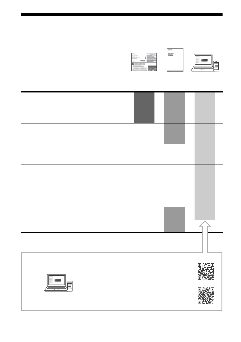
Manuals provided for this product
Startup
Guide
Operating
Instructions
(this booklet)
Help Guide
(online)
For the customers in Europe
http://rd1.sony.net/help/ha/strdn108/h_eu/
For the customers in other areas
http://rd1.sony.net/help/ha/strdn108/h_zz/
To read the Help Guide, go to the following website:
The following manuals are provided for this product.
The information included in each manual is as shown below:
Preparation
Installation
Connections
Initial Setup
Basic operations
Listening/Watching
Advanced operations
Listening/Watching
Advanced operations
BLUETOOTH features
Network features
Multi-zone features
Other features
Adjusting Settings
Troubleshooting
Precautions / Specifications
GB
6

About These Operating
Table of Contents
Instructions
These Operating Instructions mainly describe
the procedures for using the remote control.
You can also use the controls on the receiver if
they have the same or similar names as those
on the remote control.
Some illustrations are presented as conceptual
drawings, and may be different from the actual
products.
These Operating Instructions cover models for
the United States, Canada, Oceanian and
European countries.
Only the USA and Canadian models are
equipped with the SPEAKERS ZONE 2 terminals
on the rear of the receiver.
The USA and Canadian models are used for
illustrative purposes in these Operating
Instructions.
The items displayed on the TV screen may vary
depending on the area.
The text enclosed in bracket ([--]) appears on
the TV screen, and the text enclosed in double
quotation mark (“--”) appears on the display
panel.
Manuals provided for this product ...............6
About These Operating Instructions ............ 7
Main features of the receiver .......................8
Supplied Accessories ................................... 11
Parts and Controls .......................................12
Preparation
Installing Speakers ......................................18
Connecting Speakers ..................................20
Connecting a TV ..........................................29
Connecting Audio-Visual Devices .............. 33
Connecting to a network ............................38
Connecting the Antenna (aerial) ................ 39
Connecting the AC Power Cord
(mains lead) ........................................... 39
Setting up the Receiver using the Easy
Setup ......................................................40
Listening/Watching
Enjoying Sound and Video .........................42
Enjoying Sound Effects ...............................46
Network functions ......................................50
Listening with BLUETOOTH headphones/
speakers ..................................................51
Additional Information
Saving power .............................................. 53
Updating the Software ...............................53
Troubleshooting .........................................54
Precautions .................................................58
Specifications ...............................................61
END USER LICENSE AGREEMENT ................66
7
GB

Main features of the receiver
Compatible with a variety of connections and high-quality audio/video
formats
Compatible with wired/wireless network, BLUETOOTH, and USB
connections
Connect a Walkman, iPod/iPhone (AirPlay), computer, NAS, or USB device to the receiver to
play content on those devices or transmit music to BLUETOOTH headphones/speakers.
Music services such as Spotify and Chromecast built-in are supported.
For details, see the Help Guide.
Compatible with the latest object-based audio formats
Dolby Atmos (page 24) and DTS:X are supported.
Compatible with high-definition playback of High- Resolution
Audio
During network audio playback or content playback on a USB device, the receiver supports
High- Resolu tion Aud io content at up to 5.6 MH z in the DSD format and at up to 192 kHz /24 bit s
in the WAV, FLAC, and AIFF formats.
Native playback of DSD files is also supported.
Compatible with high-definition 4K video formats*
The receiver supports 4K HDR and HDCP 2.2, letting you enjoy high-definition video images
(page 33).
* You need to change the setting of [HDMI Signal Format] depending on the input video signal.
Functions for an optimum surround environment
Automatically calibrating your viewing and listening environment
to create an ideal surround space using Auto Calibration (D.C.A.C.
EX*)
D.C.A.C. EX measures and calibrates the distance, angle, level, and frequency characteristics of
the speakers using the supplied stereo calibration microphone (page 40).
The optimum sound is then produced by simulating ideal speaker positions and angles
(Speaker Relocation**).
Calibration functions for sound fields corresponding to various
speaker installation conditions
Phantom Surround Back**: Allows you to enjoy a surround-sound effect acoustically
equivalent to that of a 7-channel speaker system, using only a 5-channel speaker system, and
when using a 5.1.2-channel speaker system, it allows you to enjoy a surround-sound effect
acoustically equivalent to that of a 7.1.2-channel speaker system.
Front Surround: Allows you to enjoy virtual surround sound with only two front speakers
(page 28).
GB
8

In-Ceiling Speaker Mode**: Reproduces more natural sound by lowering the position of audio
output from speakers installed in the ceiling.
Center Speaker Lift Up**: Reproduces natural sound that feels more authentic by lifting the
sound from the center speaker up to the height of the screen.
* Digital Cinema Auto Calibration EX
** For details, see the Help Guide.
Audio technologies for high-definition music playback
Sound fields selectable by preference
You can select from a variety of sound fields according to speaker connections or input sources
(2ch Stereo, Direct, Auto Format Decoding, etc.) (page 46).
Upscaling of existing sound sources into higher resolutions with
the same quantity of information as High-Resolution Audio using
DSEE HX (Digital Sound Enhancement Engine HX)*
The receiver restores signals in the micro region of compressed sound sources by up-sampling
the sampling frequency and expanding the bit depth to the equivalent of a maximum of 192 kHz/
24 bits, letting you enjoy CDs and lossy compressed sound sources such as MP3 files in expressive
sound quality closer to the original.
High-definition BLUETOOTH music playback (LDAC)*
LDAC allows approximately three times more data to be transmitted than with the previous
BLUETOOTH A2DP-SBC (328 kbps, 44.1 kHz). The receiver supports wireless playback
(transmission/reception) of high-quality sound when speakers, headphones, a Walkman, or a
smartphone that supports LDAC are connected to the receiver via a BLUETOOTH connection.
Reproduction of authentic impact and realistic sense of immersion
in movies (Sound Optimizer)*
Sound Optimizer calibrates the disparity in acoustic frequency characteristic between movie
production and playback caused by different volume levels, reproducing the impact and
immersive surround effect that the movie's sound engineers intended even when it is played
back at low volume levels in a home.
* For details, see the Help Guide.
Other useful functions
Compatible with "SongPal" and "SongPal Link"*
SongPal is a dedicated app for operating SongPal compatible audio devices manufactured by
Sony from a smartphone or tablet device. It lets you operate the receiver from the smartphone
or tablet device and use the SongPal Link function.
Equipped with an ARC-compatible HDMI jack
TV sound can be output from the receiver using only one HDMI cable (page 31).
9
GB

Supports bi-amping of front speakers
You can enhance the sound quality of the front speakers by connecting different amplifiers to the
tweeter and woofer using a bi-amplifier connection (page 26).
Support for music and video playback in different rooms
The Wireless Multi-Room function** lets you listen to the same music in different rooms.
The multi-zone features let you output audio and video signals to another room.
* For details, see the Help Guide.
** You can enjoy the sound of the device that is connected to the receiver. The sound is delayed behind the
picture.
10
GB
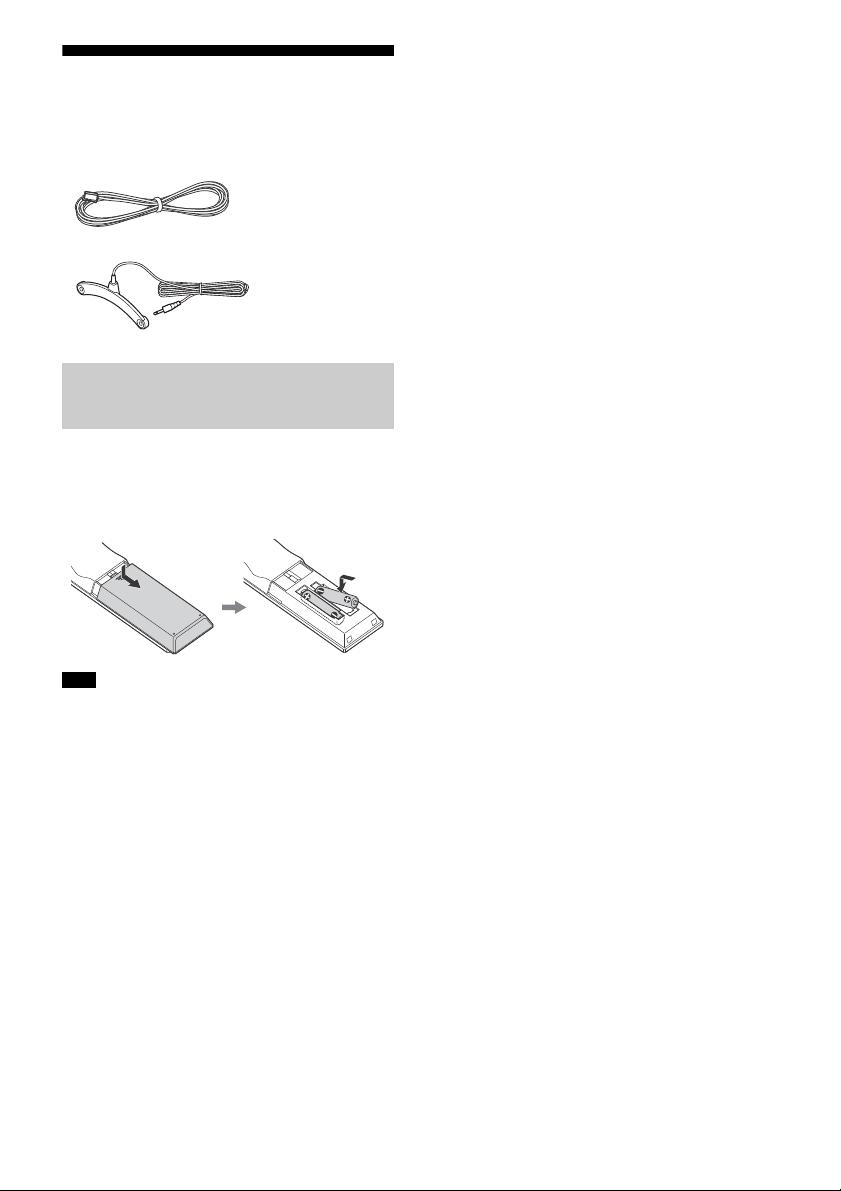
Supplied Accessories
Remote control (1)
R03 (size AAA) batteries (2)
FM wire antenna (aerial) (1)
Calibration microphone (1)
Inserting batteries into the
remote control
Insert two R03 (size AAA) batteries (supplied)
in the remote control. Make sure that the +
and – ends are in the correct position when
installing batteries.
Note
Do not leave the remote control in an extremely
hot or humid place.
Do not use a new battery with old ones.
Do not mix manganese batteries and other kinds
of batteries.
Do not expose the remote control sensor to direct
sunlight or lights. Doing so may cause a
malfunction.
If you do not intend to use the remote control for
an extended period of time, remove the batteries
to avoid possible damage from battery leakage
and corrosion.
When the receiver no longer responds to the
remote control, replace both of the batteries with
new ones.
GB
11
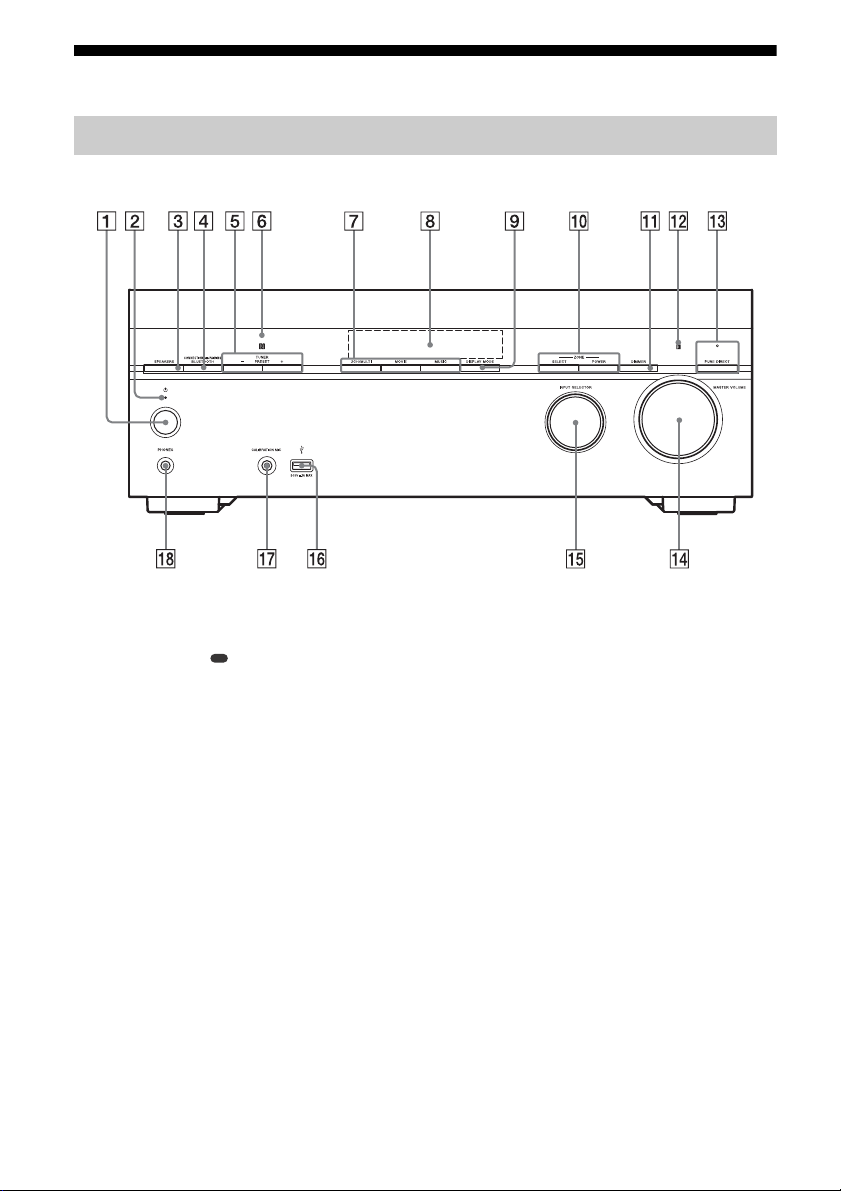
Parts and Controls
Receiver
Front panel
(power) (page 39)
Power indicator
SPEAKERS (page 41)
CONNECTION PAIRING BLUETOOTH
Operates the BLUETOOTH function.
TUNER PRESET +/–
Selects preset stations or channels.
NFC sensor
2CH/MULTI, MOVIE, MUSIC (page 46)
Display panel (page 13)
DISPLAY MODE
Switches information on the display panel.
ZONE SELECT, ZONE POWER (page 43,
44)
DIMMER
Adjusts the brightness of the display panel.
Remote control sensor
Receives signals from remote control.
PURE DIRECT
The indicator above the button lights up when
the Pure Direct function is activated.
MASTER VOLUME (page 42)
INPUT SELECTOR (page 42)
(USB) port
Connect a USB device here.
CALIBRATION MIC jack (page 41)
GB
12
PHONES jack
Connect headphones here.
Power indicator
Green: The receiver is turned on.
Amber: The receiver is in standby mode,
and you have set one of the following:
[Control for HDMI], [Remote Start]*,
[Bluetooth Standby], or [Network
Standby]* is set to [On].
[Standby Through] is set to [On] or [Auto].
[Zone2 Power] or [HDMI Zone Power] is
set to [On].
The indicator goes off: The receiver is in
standby mode and all of the following
settings are set to [Off]:
[Control for HDMI]
[Standby Through]
[Remote Start]*
[Bluetooth Standby]
[Network Standby]*
[Zone2 Power] and [HDMI Zone Power]
* For USA, Canadian and Oceanian models only.
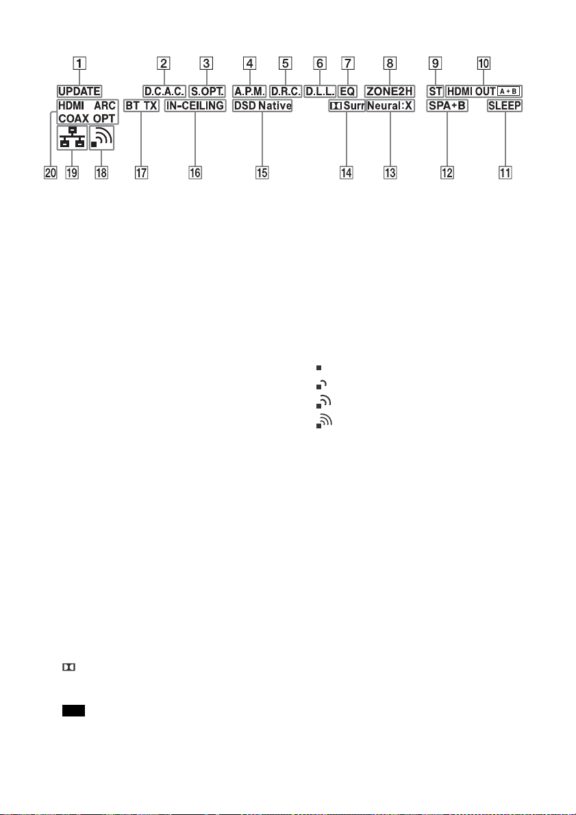
Indicators on the display panel
UPDATE
Lights up when new software is available.
D.C.A.C.
Lights up when the measurement results of the
Auto Calibration (D.C.A.C. EX) function are
applied.
S.OPT.
Lights up when the Sound Optimizer function is
activated.
A.P.M.
Lights up when the A.P.M. (Automatic Phase
Matching) function is activated. You can only
set the A.P.M. function in the D.C.A.C. function.
D.R.C.
Lights up when dynamic range compression is
activated.
D.L.L.
Lights up when the D.L.L. (Dig ital Legato Linear)
function is activated.
EQ
Lights up when the equalizer is activated.
ZONE2, ZONE H
“ZONE2” lights up when the power for Zone 2 is
on.
“ZONE H” lights up when the power for HDMI
zone is on.
ST
Lights up when the receiver tunes to a FM
stereo broadcast.
HDMI OUT A + B
Indicates the HDMI OUT jacks that currently
output the audio/video signals.
SLEEP
Lights up when the sleep timer is activated.
Speaker system indicator (page 41)
Neural:X
Lights up when DTS Neural:X decoding is
activated.
Surr
Lights up when Dolby Surround decoding is
activated.
Note
These indicators may not light up depending on
the speaker pattern setting.
DSD Native
Lights up when DSD native playback function is
activated.
IN-CEILING
Lights up when the In-Ceiling Speaker Mode is
activated.
BLUETOOTH indicator
“BT” lights up when a BLUETOOTH device is
connected. Flashes while connecting.
“BT TX” lights up when an Audio-Visual device
connected to the receiver sends audio to the
BLUETOOTH headphones/speakers.
Wireless LAN signal strength indicator
Show the strength of the wireless LAN signal.
No signal
Weak
Moderate
Strong
Wired LAN indicator
Lights up when a LAN cable is connected.
Input indicator
Lights up to indicate the current input.
HDMI
Digital signals are input through the selected
HDMI jack.
ARC
TV input is selected and Audio Return Channel
(ARC) signals are detected.
COAX
Digital signals are input through the COAXIAL
jack.
OPT
Digital signals are input through the OPTICAL
jack.
GB
13
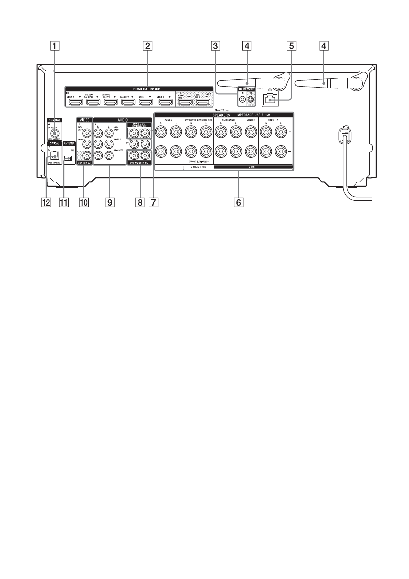
Rear panel
COAXIAL IN jack
HDMI IN/OUT jacks*
IR REMOTE IN/OUT jacks
You can control the receiver from a distance by
connecting an IR repeater (not supplied) to the
IR REMOTE IN jack.
You can start or stop playback of devices such
as a CD player connected to the receiver by
connecting an IR blaster (not supplied) to the
IR REMOTE OUT jack.
Wireless LAN antenna
LAN port
SPEAKERS terminals
Only the USA and Canadian models are
equipped with the SPEAKERS ZONE 2 terminals.
The USA and Canadian models are used for
illustrative purposes in these Operating
Instructions.
ZONE 2 OUT jacks
SUBWOOFER OUT jacks
AUDIO IN jacks
VIDEO IN/MONITOR OUT jacks
FM ANTENNA terminal
OPTICAL IN jack
* All of the HDMI IN/OUT jacks on the receiver
support HDCP 2.2. HDCP 2.2 is newly enhanced
copyright protection technology that is used to
protect content such as 4K movies.
GB
14
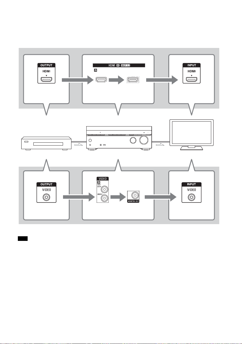
About input/output of video signals
HDMI OUT jack Any one of
the HDMI IN
HDMI OUT A (TV)
or HDMI OUT B/
HDMI ZONE
HDMI IN jack
Audio-Visual device The receiver TV
VIDEO OUT jack VIDEO IN MONITOR OUT VIDEO IN jack
The digital video signals input to the HDMI IN jacks of this receiver are output from HDMI OUT A
(TV) or HDMI OUT B/HDMI ZONE jacks only. The analog video signals input from VIDEO IN jacks
are output from the MONITOR OUT jack only.
Use the following illustration as reference when you connect the receiver, AV device, and TV.
Note
When you connect the TV to the MONITOR OUT jack, the home menu of this receiver is not displayed on the TV
screen. To operate this receiver using the menu on the TV screen, connect the TV to the HDMI OUT A (TV) or
HDMI OUT B/HDMI ZONE jacks.
GB
15
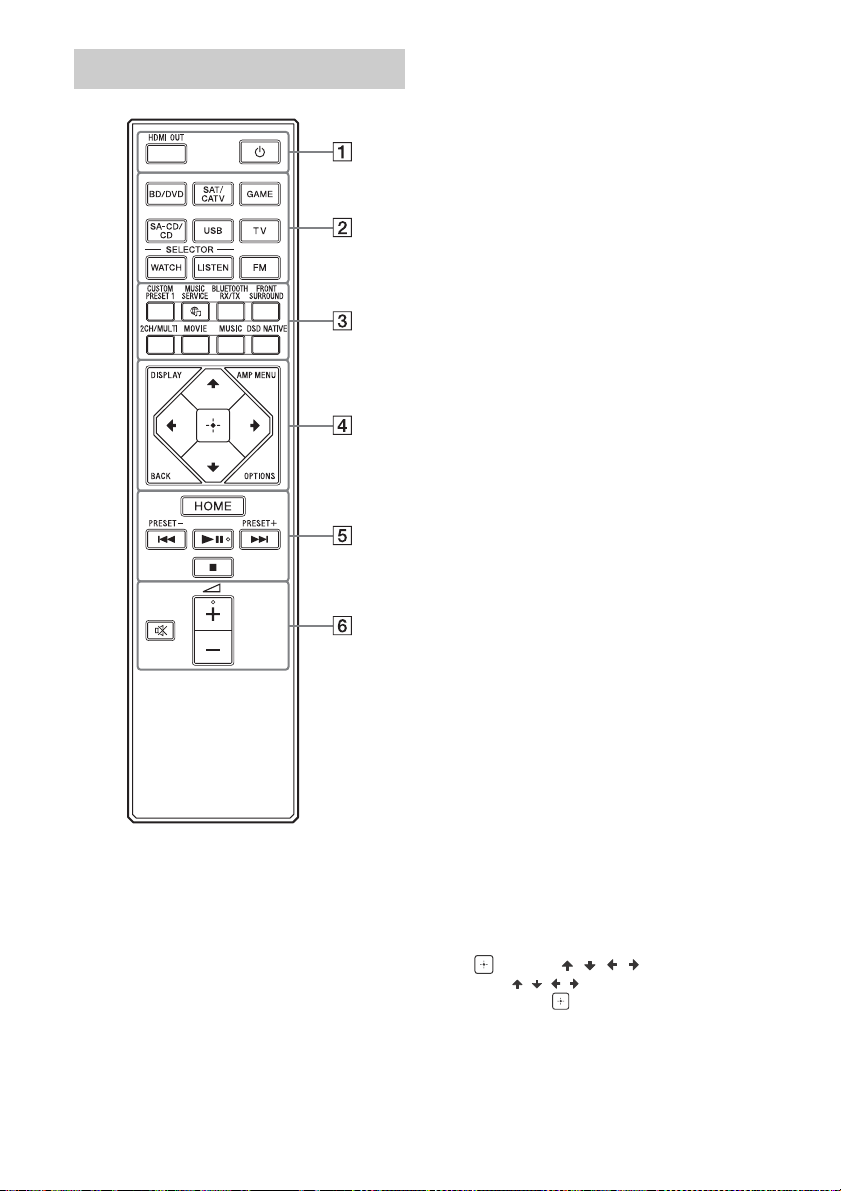
Remote control
(power)
Turns the receiver on or sets it to the standby
mode.
HDMI OUT
Switches the output for two TVs connected to
the HDMI OUT A (TV) and HDMI OUT B/HDMI
ZONE jacks.
When [HDMI Out B Mode] is set to [Main] in the
[HDMI Settings] menu, output is toggled
between “HDMI A”, “HDMI B”, “HDMI A+B” and
“HDMI OFF” each time the button is pressed.
When [HDMI Out B Mode] is set to [Zone],
output is toggled between “HDMI A” and “HDMI
OFF” each time the button is pressed.
Select “HDMI OFF” to turn off the output for the
HDMI OUT A (TV) and HDMI OUT B/HDMI ZONE
jacks.
Input buttons
BD/DVD, SAT/CATV, GAME, SA-CD/CD,
USB, TV, FM
Selects the input channel connected to the
device you want to use. When you press any of
the input buttons, the receiver turns on.
WATCH, LISTEN
Allows you to display the Watch or Listen
screen directly without the need to select it on
the home menu.
Press WATCH to display the Watch screen or
LISTEN to display the Listen screen. Then press
either WATCH or LISTEN to select the input you
want to view.
CUSTOM PRESET 1
Saves and recalls various settings for the
receiver. Press to select the custom preset
setting. Press and hold to save the current
settings to a preset.
MUSIC SERVICE
If you have listened to music streamed from
1), 2)
Spotify
SERVICE to play the same music from exactly
the point it was left off.
For details on operation, visit the Help Guide.
on this receiver, press MUSIC
BLUETOOTH RX/TX
Switches the [Bluetooth Mode] to [Receiver] or
[Transmitter].
In [Receiver] mode, the receiver receives and
outputs audio from the player.
In [Transmitter] mode, the receiver sends audio
to BLUETOOTH headphones/speakers.
FRONT SURROUND, 2CH/MULTI, MOVIE,
MUSIC
Selects a sound field.
DSD NATIVE
Activates the DSD Native function.
DISPLAY
Displays information on the TV screen.
AMP MENU
Displays the menu on the display panel to
operate the receiver.
BACK
Returns to the previous menu or exits a menu
or on-screen guide that is displayed on the TV
screen.
OPTIONS
Displays the options menus.
(enter), / / /
Press , , , to select the menu items.
Then, press
to enter the selection.
GB
16

HOME
Displays the home menu on the TV screen.
/ (previous/next),
(play/pause)
3)
, (stop)
Skip, play, pause, stop operation.
PRESET +/–
Selects preset stations or channels.
(volume) +3)/–
Adjusts the volume level of all speakers at the
same time.
(muting)
Turns off the sound temporarily. Press the
button again to restore the sound.
1)
Available services may vary depending on your
location.
2)
Spotify playback using the receiver is limited to
Spotify Premium accountholders.
3)
The and + buttons have tactile dots. Use
the tactile dots as reference when operating the
receiver.
Note
The above explanation is intended to serve as
examples.
Depending on the model of your connected
device, some functions explained in this section
may not work with the supplied remote control.
GB
17
Preparation
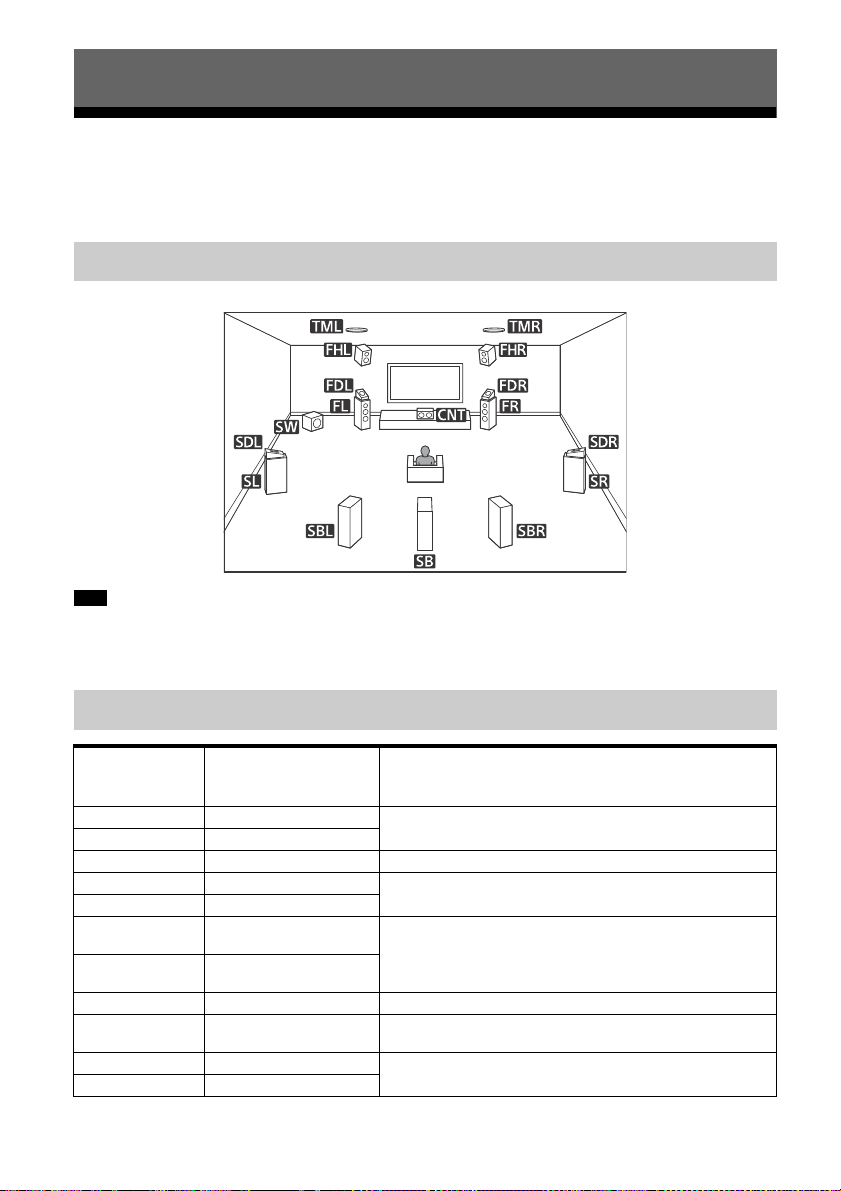
Installing Speakers
You can connect up to 7 speakers and 2 subwoofers to this AV receiver. Place the speakers and
subwoofers according to the speaker system of your preference.
Location of each speaker
Note
When you connect only one surround back speaker (SB), place the surround back speaker directly behind the
listening position.
As the subwoofer (SW) does not emit highly directional signals, you can place it wherever you want.
Names and functions of speakers
Abbreviations
used in
illustrations
FL Front left speaker
FR Front right speaker
CNT Center speaker Produces vocal sounds from center channel.
SL Surround left speaker
SR Surround right speaker
SBL
SBR
SB Surround back speaker Produces sounds from surround back channel.
SW Subwoofer
TML Top middle left speaker
TMR Top middle right speaker
GB
18
Speaker name Functions
Produces sounds from front left/right channels.
Produces sounds from surround left/right channels.
Surround back left
speaker
Surround back right
speaker
Produces sounds from surround back left/right channels.
Produces LFE (low frequency effect) channel sounds and
reinforces bass parts of other channels.
Produces sounds from top middle left/right channels.
Abbreviations
Speaker name Functions
used in
illustrations
FDL
FDR
SDL
SDR
FHL Front high left speaker
FHR Front high right speaker
Front Dolby Atmos
enabled left speaker
Front Dolby Atmos
enabled right speaker
Surround Dolby Atmos
enabled left speaker
Surround Dolby Atmos
enabled right speaker
Produces sounds from the top middle left/right channels
and reflects these sounds off the ceiling. Enables playing
back sounds of Dolby Atmos 3D movies without the need to
install ceiling speakers.
Produces sounds from the top middle left/right channels
and reflects these sounds off the ceiling. Enables playing
back sounds of Dolby Atmos 3D movies without the need to
install ceiling speakers.
Produces vertical sound effects from front height left/right
channels.
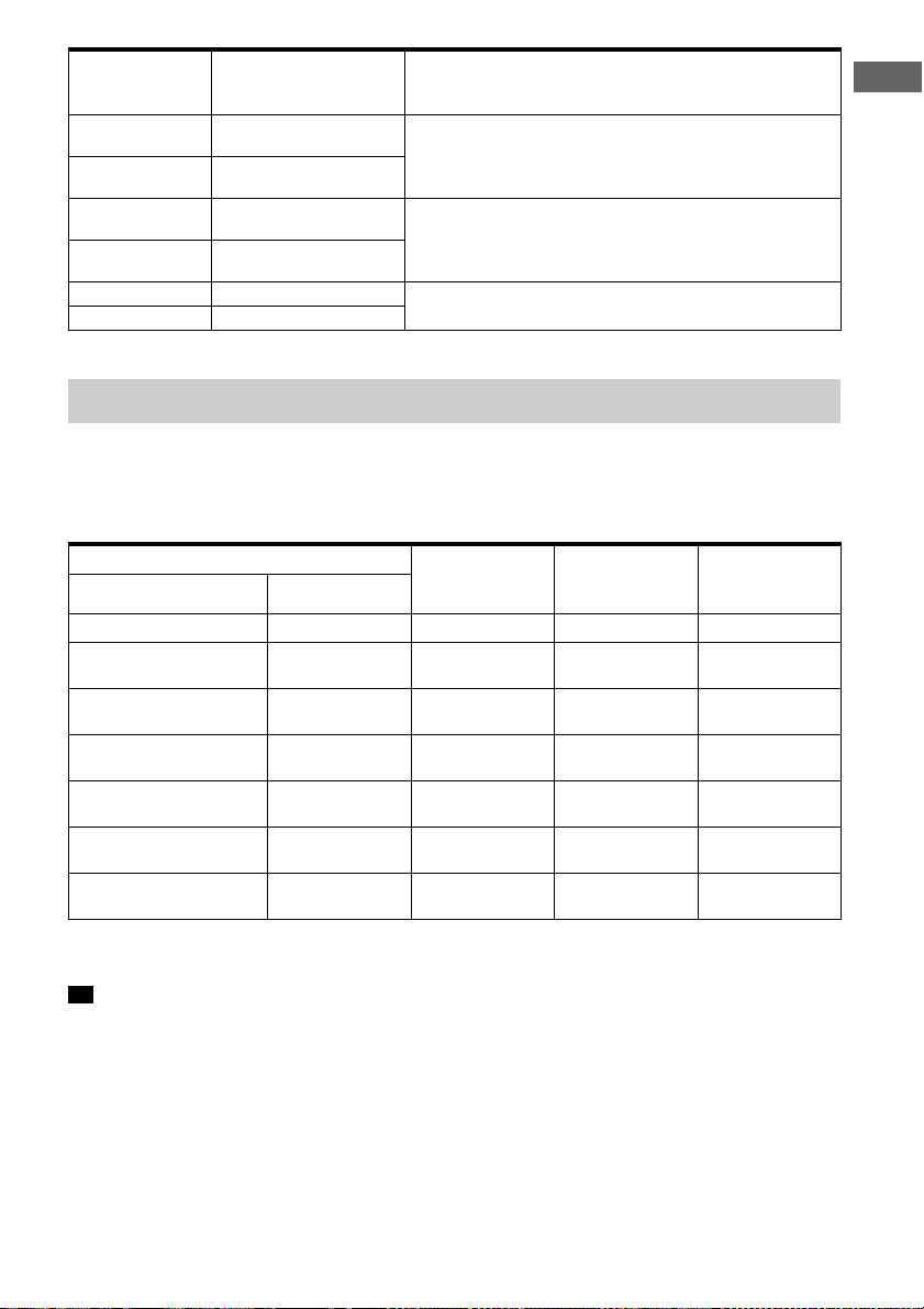
Speaker configuration and speaker pattern settings
Select the speaker pattern according to the speaker configuration which you are using.
The table below shows examples of speaker configurations and speaker pattern settings. For
speaker placement and connection diagrams for each speaker configuration example, see
“Examples of speaker connections” (page 21).
Preparation
Speaker configuration in each zone [Surround Back
Main zone Zone 2
5.1-channel Not used — [5.1] 21
7.1-channel using
surround back speakers
5.1.2-channel using top
middle speakers
5.1.2-channel using Dolby
Atmos enabled speakers
5.1-channel with Zone 2
speakers
5.1-channel with BiAmplifier connection
2.1-channel (for enjoying
Front Surround)
* You can only set [Surround Back Speaker Assign] if the speaker pattern is set to a setting that does not have
surround back and height speakers.
Tip
The receiver allows you to enjoy a surround-sound effect acoust ically e quivale nt to that of up to a 7.1. 2-ch anne l
speaker system when you select [Type A] or [Type B] for [SpeakerRelocation/PhantomSurroundBack] in the
[Speaker Settings] menu.
When setting [SpeakerRelocation/PhantomSurroundBack], perform Auto Calibration beforehand (page 40).
Not used — [7.1] 22
Not used — [5.1.2 (TM)] 23
Not used — [5.1.2 (FD)] 24
2-channel [Zone2] [5.1] 25
Not used [BI-AMP] [5.1] 26
Not used — [2.1] 28
Speaker
Assign]*
[Speaker
Pattern] setting
For connection,
see page
GB
19
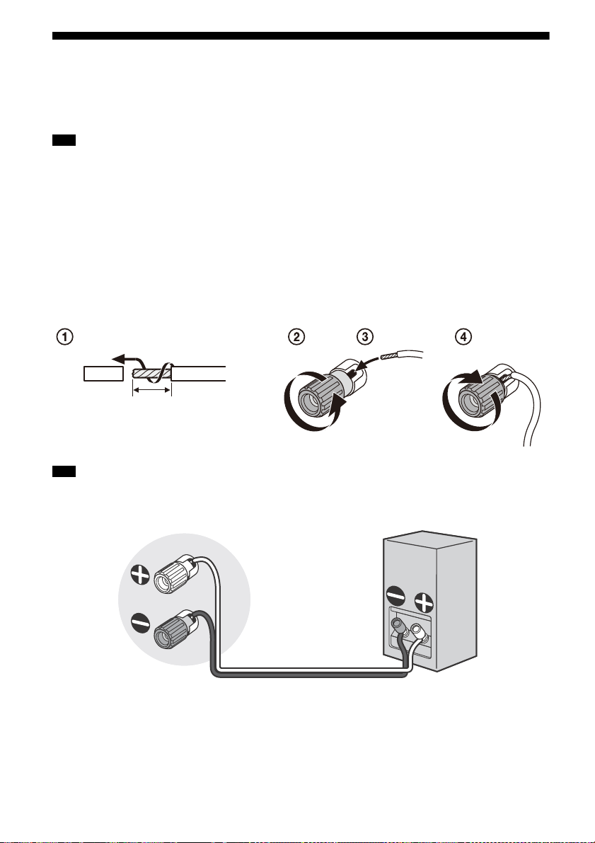
Connecting Speakers
10mm
(13/32 in)
This receiver allows you to connect up to 7.1-channel system.
The speaker layout diagram is a guide for the ideal speaker placement. You do not need to adjust
your speaker placement exactly the same as the diagram.
Note
Before connecting cables, be sure to disconnect the AC power cord (mains lead).
Before connecting the AC power cord (mains lead), make sure that metallic wires of the speaker cables are
not touching each other between the SPEAKERS terminals.
When you connect a subwoofer with an auto standby function, turn off the function when watching movies.
If the au to standby function is set to on, it turn s to standby mode au tomatically based on the level of the inp ut
signal to the subwoofer, and the sound may not be output.
If you have two subwoofers, you can connect them to both SUBWOOFER OUT jacks.
How to connect speaker cables
Be sure to connect the speaker cables correctly to the terminals of the speaker and this receiver.
Also, be sure to tightly twist the speaker wire strands and insert them securely into the speaker
terminals.
Note
Be sure not remove too much of the speaker cable sleeves, so as to prevent the wires of the speaker cables
from touching each other.
Connect speaker cables properly with the polarities (+/–) matched between the receiver and the speakers.
Improper connection may result in fatal damage to the receiver.
GB
20
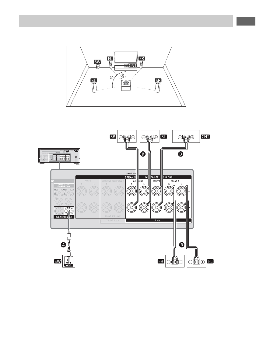
Examples of speaker connections
30˚
100˚ – 120˚
Surround speakers
Monaural audio cable (not supplied)
Speaker cable (not supplied)
Front speakers
Subwoofer
Center speaker
5.1-channel speaker system
Preparation
GB
21
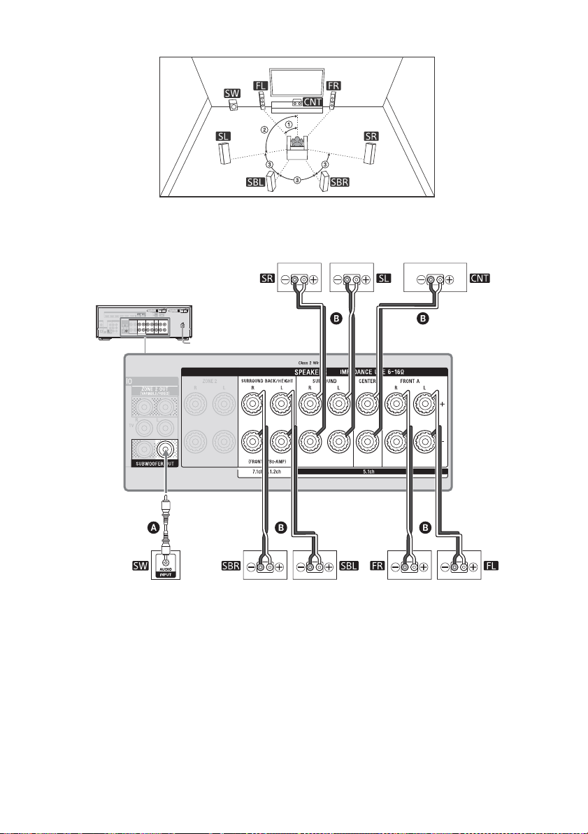
7.1-channel speaker system using surround back speakers
30˚
100˚ – 120˚
Same angle
Surround back speakers*
Surround speakers
Monaural audio cable (not supplied)
Speaker cable (not supplied)
Front speakersSubwoofer
Center speaker
* If you connect only one surround back speaker, connect it to the L (+/–) terminals.
After you have made the connection, select a speaker pattern with only one surround back speaker
connected for [Speaker Pattern] in [Speaker Settings].
22
GB

5.1.2-channel speaker system using top middle speakers
30˚
100˚ – 120˚
Top mi dd le speaker s*
Surround speakers
Monaural audio cable (not supplied)
Speaker cable (not supplied)
Front speakers
Subwoofer
Center speaker
Preparation
* After you have made the connection, set [Speaker Pattern] in [Speaker Settings] to [5.1.2 (TM)].
23
GB

5.1.2-channel speaker system using Dolby Atmos enabled speakers
30˚
100˚ – 120˚
Front Dolby Atmos
enabled speakers*
Surround speakers
Monaural audio cable (not supplied)
Speaker cable (not supplied)
Front speakersSubwoofer
Center speaker
* After you have made the connection, set [Speaker Pattern] in [Speaker Settings] to [5.1.2 (FD)].
24
GB

5.1-channel speaker system with Zone 2 speakers
30˚
100˚ – 120˚
Main zone Zone 2
Speakers (Zone 2)
(for USA and Canadian
models only)*
Surround speakers
Monaural audio cable (not supplied)
Speaker cable (not supplied)
Front speakersSubwoofer
Center speaker
Speakers (Zone 2)
(for other models)*
Preparation
* Only USA and Canadian models are equipped with the SPEAKERS ZONE 2 terminals.
The USA and Canadian models are used for illustrative purposes in these Operating Instructions.
For other models, connect the speakers in Zone 2 to the SPEAKERS SURROUND BACK/HEIGHT (FRONT B/
BIAMP/ZONE 2) terminals.
For details on using the Zone 2 speakers, see “Enjoying sound from speakers located in other rooms (Zone
2)” (page 43).
Note
For USA and Canadian models, be sure to connect the speakers in Zone 2 to the SPEAKERS ZONE 2 terminals.
GB
25

5.1-channel speaker system with Bi-Amplifier connection
30˚
100˚ – 120˚
Monaural audio cable (not supplied)
Speaker cable (not supplied)
Surround speakers Center speaker
Subwoofer
Front speaker
When the front speakers are Bi-wire speakers, which are equipped with separate terminals for
high-frequency sounds (tweeter) and low-frequency sounds (woofer), you can make the biamplifier connection. Connect each pair of terminals for tweeter and woofer to the SPEAKERS
FRONT A terminals and SPEAKERS SURROUND BACK/HEIGHT terminals of this receiver. You can
enjoy higher quality sound playback if you operate the tweeter and woofer using separate
amplifiers.
Make sure that metal fittings of Hi/Lo attached to the speakers have been removed from the speakers to avoid
receiver malfunction.
After you have made the connection, set [Surround Back Speaker Assign] in [Speaker Settings] to [BI-AMP].
26
GB

Note
You can only set [Surround Back Speaker Assign] if the speaker pattern is set to a setting that does not have
surround back and height/overhead speakers (page 19).
Preparation
GB
27

2.1-channel speaker system (for enjoying Front Surround)
30˚
1.5 m – 3 m
Set the height of a tweeter of the front
speaker at the same height as your ears.
Monaural audio cable (not supplied)
Speaker cable (not supplied)
Front speakersSubwoofer
If you select [Front Surround] for the sound field setting, you can enjoy virtual surround effects
using only the two front speakers.
Place the speakers as shown below to enjoy Front Surround.
Tip
Change the direction of the front speakers little by little to search for and set the direction that gives you the
best surround effects.
28
GB

Connecting a TV
Connect a TV to the HDMI OUT or MONITOR OUT jack.
The menu is displayed on the TV screen only when you connect the TV to the HDMI OUT jack.
Sony recommends that you use the HDMI OUT jack to connect the TV because in many cases you
will have to perform the settings of this receiver using the menu.
For a 4K TV connection, visit the Help Guide.
Notes on connection
Before connecting cables, be sure to disconnect the AC power cord (mains lead).
Sony recommends that you use an HDMI cable made by Sony or another HDMI-authorized
cable. Be sure to use a High Speed HDMI Cable with Ethernet. For video signals that require a
high bandwidth such as 4K/60p 4:4:4, 4:2:2 and 4K/60p 4:2:0 10 bit etc., be sure to use a
Premium High Speed HDMI Cable with Ethernet, which supports bandwidths up to 18 Gbps.
When you use high bandwidth video formats such as 4K/60p 4:4:4, 4:2:2 and 4K/60p 4:2:0
10 bit, be sure to set the HDMI signal format. For details, see “Setting HDMI signal format”
(page 42).
We do not recommend using an HDMI-DVI conversion cable. If you connect an HDMI-DVI
conversion cable to a DVI-D device, the sound and/or image may be lost. Connect separate
audio cables or digital connecting cables, then reassign the input jacks if the sound is not
output correctly.
Depending on the status of the connection between the TV and the antenna (aerial), the image
on the TV screen may be distorted. If this is the case, place the antenna (aerial) farther away
from the receiver.
When connecting an optical digital cable, insert the plugs straight until they click into place.
Do not bend or tie optical digital cables.
All of the digital audio jacks are compatible with 32 kHz, 44.1 kHz, 48 kHz, and 96 kHz sampling
frequencies.
When connecting a TV to the receiver via the TV IN jacks of the receiver, set the sound output
jack of the TV to “Fixed” if it can be switched between “Fixed” or “Variable.”
When you connect the TV to HDMI OUT B/HDMI ZONE jack, be sure to set [HDMI Out B Mode]
to [Main] in the [HDMI Settings] menu. The home menu is not displayed on the TV screen if
[HDMI Out B Mode] is set to [Zone].
Preparation
29
GB

Connecting a TV incompatible with the Audio Return Channel (ARC)
Audio signals
Optical digital audio cable (not supplied)
Audio cable (not supplied)
HDMI cable (not supplied)
Recommended connection
Alternative connection
Audio/Video
signals
or
function via an HDMI connection
When you connect the receiver to a TV using the HDMI cable , the receiver can output audio
and video signals to the TV. Note, however, that you also need to connect the optical digital cable
or audio cable to the TV in order to output TV audio from the speakers connected to the
receiver.
30
GB

Connecting a TV compatible with the Audio Return Channel (ARC)
HDMI cable (not supplied)
Audio/Video signals
function via an HDMI connection
With just one HDMI cable connection, you can listen to the TV audio from the speakers connected
to the receiver while the receiver sends audio and video signals to the TV.
Preparation
Note
For this connection, you need to turn the Control for HDMI function on. Press HOME, then select [Setup] –
[HDMI Settings] – [Control for HDMI] – [On].
You also need to perform the setting on the TV menu. Turn on the ARC function.
Tip
If the HDMI jack of the TV (labeled “ARC”) is already connected to another device, disconnect the device and
connect the receiver.
GB
31

Connecting a TV without HDMI jacks
Video cable (not supplied)
Audio cable (not supplied)
Optical digital audio cable (not supplied)
Recommended connection
Alternative connection
Video signals
Audio signals
or
You need to connect the optical digital audio cable or audio cable to the TV in addition to
connecting the video cable .
Note
When you have connected the receiver and TV using the above method, video from the device connected to
the VIDEO IN jacks is displayed on the TV.
When you connect the receiver and TV using the above method, the menu is not displayed on the TV screen.
To perform operations using the menu, you need to connect the TV via an HDMI connection.
32
GB

Connecting Audio-Visual Devices
Super Audio CD
player or CD player
Audio/Video
signals
Game console such
as PlayStation 4
Blu-ray Disc™ player,
DVD player
DVD player
Cable box or
satellite box
Audio/Video
signals
Audio/Video
signals
Audio/Video
signals
Audio/Video
signals
HDMI cable (not supplied)
Game console, DVD
player, etc.
Audio/Video
signals
Connecting devices with HDMI jacks
Before connecting cables, be sure to disconnect the AC power cord (mains lead).
The HDMI IN jacks of the receiver are compatible with HDCP 2.2. To watch content protected by
HDCP 2.2, such as 4K content, connect these HDMI IN jacks to HDCP 2.2-compatible HDMI jacks
on the player. Refer to the operating instructions of the connected device for details.
Preparation
33
GB

Tip
This connection is an example. You can connect each HDMI device to any HDMI IN jacks.
The BD/DVD and SA-CD/CD inputs have better sound quality. When you need a higher sound quality, connect
your device to these HDMI IN jacks and select them as the input.
The image quality depends on the type of connecting jack. We recommend you connect your devices via an
HDMI connection if they have HDMI jacks.
34
GB

Connecting devices with jacks other than HDMI jacks
Audio signals
Audio cable (not supplied)
Video cable (not supplied)
Coaxial digital cable (not supplied)
Cable box or satellite box
VCR, DVD recorder,
camcorder, video game
Video signals
Audio signals
or
Super Audio CD player, CD player,
Turn table *
Audio signals Video signals
Before connecting cables, be sure to disconnect the AC power cord (mains lead).
Preparation
* To connect a turntable that only has a PHONO output jack, you need to connect a phono equalizer (not
supplied) between the turntable and this receiver.
35
GB

Note
Audio cable (not supplied)
Amplifier/
Receiver
Main zone Zone 2
Speaker Speaker
Audio signals
To listen to the sounds from a device connected to the AUDIO IN jacks, do not connect any device to the HDMI
IN, COAXIAL IN, and OPTICAL IN jacks, which are labeled with the same device name (such as SAT/CATV, TV,
VIDEO 1, and SA-CD/CD).
Tip
You can connect devices other than those indicated above to the AUDIO IN jacks (SAT/CATV, VIDEO 1, and SA-
CD/CD).
You can rename each input so that the name can be displayed on the display panel of the receiver. For details,
refer to “Changing the name for each input (Name)” in Help Guide.
Connecting another amplifier in Zone 2
Before connecting cables, be sure to disconnect the AC power cord (mains lead).
Note
Only audio signals from [USB], [Bluetooth] (only when [Bluetooth Mode] is set to [Receiver]), [Home Network],
[Music Service List], and [FM TUNER] and audio signals input from AUDIO IN jacks located on the rear panel of
the receiver are output to the Zone 2 speakers.
External digital input from OPTICAL IN, COAXIAL IN and HDMI IN jacks cannot be output to Zone 2.
If you set [DSD Native] in [Audio Settings] to [On], no audio signals for DSD content from [USB] or [Home
Network] are output to the Zone 2 speakers.
GB
36

Connecting another amplifier or TV in the HDMI zone
Amplifier/
Receiver
Main zone HDMI zone
Speaker SpeakerTV
HDMI cable (not supplied)
Recommended connection
Alternative connection
Audio/Video
signals
Before connecting cables, be sure to disconnect the AC power cord (mains lead).
Note
To use this connection, set [HDMI Out B Mode] in the [HDMI Settings] menu to [Zone].
Preparation
GB
37

Connecting to a network
LAN cable (not supplied)
Server
(computer, etc.)
Router
Modem
Internet
Server
(computer, etc.)
Internet
Modem
Router
Select the connection method based on your
LAN (Local Area Network) environment.
The following illustrations are configuration
examples of a home network with the
receiver and a server.
When using wired LAN
connection
Connect your receiver to the network using a
LAN cable* (not supplied).
When using wireless LAN
connection
Note
Audio playback on a server may occasionally be
interrupted if you use a wireless connection.
When using a wireless connection, stand up both
wireless LAN antennas for better performance.
* We recommend using category 7 cables.
38
GB

Connecting the Antenna
FM wire antenna (aerial)
(supplied)
To th e w al l
outlet
(aerial)
Connecting the AC Power Cord (mains lead)
Preparation
Before connecting the antenna (aerial), be
sure to disconnect the AC power cord (mains
lead).
Note
Be sure to fully extend the FM wire antenna (aeria l).
After connecting the FM wire antenna (aerial), keep
it as horizontal as possible.
Before connecting the AC power cord (mains
lead), be sure to make connections for
speakers and the other devices.
1 Connect the AC power cord
(mains lead) to a wall outlet.
2 Press (power) to turn on the
receiver.
You can also turn on the receiver using
(p owe r) o n the rem ote con tro l. To tur n
off the receiver, press (power) again.
39
GB

Setting up the Receiver
Easy Setup
Welcome!
: Choose
: Go back
: Continue
: Apply the selection
Select your language.
English
Español
Français
Deutsch
Setup
Easy Setup
Restarts Easy Setup to configure basic settings. Follow the on-screen instructions.
Speaker Settings
Audio Settings
Select Back
BACK
HDMI Settings
Input Settings
Network Settings
Bluetooth Settings
Zone Settings
using the Easy Setup
To perform initial setup of the receiver, make
sure a TV is connected to the receiver
(page 29). Then, switch the input of the TV to
the input to which the receiver is connected.
Note
It is not possible to perform the Easy Setup
procedure using the indications on the front display
panel.
When you turn on the receiver for the first
time or after the receiver is initialized, the
Easy Setup screen appears on the TV screen.
Follow the on-screen instructions to make the
basic settings using / / / and .
If the Easy Setup screen does not appear or
you want to display the Easy Setup screen
manually, you can display it by pressing
HOME, then select [Setup] – [Easy Setup].
What you can do with Easy Setup
By performing Easy Setup, you can complete:
1: Language selection
2: Speaker settings
Check your speaker system and perform
Auto Calibration according to the
configuration and arrangement of your
speaker system.
3: Internet settings
Select the network connection method and
configure settings to connect the receiver
to the network.
Performing Auto Calibration
(D.C.A.C. EX)
Before you perform Auto
Calibration
Disconnect the headphones.
Remove any obstacles between the
calibration microphone and the speakers.
Auto Calibration is not available when
[Bluetooth Mode] is set to [Transmitter].
For accurate measurement, make sure the
environment is quiet and free from noise.
Set the speaker output to a setting other
than ”SPK OFF.” See “Selecting the front
speakers” (page 41).
Confirm the active subwoofer setup
Before using a subwoofer, turn on the
subwoofer and turn up the volume. Turn
the LEVEL to just before the mid-point.
When a subwoofer with a crossover
frequency function is connected, set the
value to maximum.
When a subwoofer with an auto standby
function is connected, set it to off
(deactivated).
GB
40
Note
Depending on the characteristics of the
subwoofer you are using, the setup distance
value may be different from the actual position.

Connect the supplied calibration
Calibration microphone
(supplied)
SPEAKERS
microphone to CALIBRATION MIC jack. Set
up the calibration microphone at your
listening position.
Note
The speakers emit very loud sound during the
calibration and the volume cannot be adjusted.
Be considerate of your neighbors and any
children who are present.
If the muting function has been activated before
you perform Auto Calibration, the muting
function will shut off automatically.
It may not be possible to take the correct
measurements or to perform Auto Calibration at
all if special speakers such as dipole speakers are
used.
If the measurement fails, follow the message,
then select [Retry]. For details on the error code
and warning message, see “List of messages
after Auto Calibration measurements” (page 57).
Selecting the front speakers
Press SPEAKERS repeatedly.
The indicators on the display panel shows
which set of terminals are selected.
SPA: Speakers connected to the SPEAKERS
FRONT A terminals.
SPB*: Speakers connected to the SPEAKERS
SURROUND BACK/HEIGHT(FRONT B/
BIAMP) terminals.
SPA+B*: Speakers connected to both the
SPEAKERS FRONT A and SPEAKERS
SURROUND BACK/HEIGHT(FRONT B/
BIAMP) terminals (parallel connection).
(None): “SPK OFF” appears on the display
panel. No audio signals are output from any
speaker terminals.
* To select "SPB" or "SPA+B", set [Surround Back
Speaker Assign] in [Speaker Settings] to [Front B].
Note
This setting is not available when headphones are
connected.
Preparation
To cancel Auto Calibration
The Auto Calibration function will be canceled
when you perform the following during the
measurement process:
Press (power).
Press the input buttons on the remote
control or turn the INPUT SELECTOR on the
receiver.
Press (muting), MUSIC or AMP MENU.
Press SPEAKERS on the receiver.
Change the volume level.
Connect the headphones.
GB
41

Listening/Watching
Watch
Select the video source connected to the receiver.
Watch
Listen
Custom
Preset
Sound
Eects
SetupZone
Controls
Enjoying Sound and Video
6 Select the device you want to
play and start playback.
When you select [FM TUNER], tune in to
your desired station by using the buttons
on the remote control according to the
guide on the TV screen. For details on
operation, visit the Help Guide.
Playing AV devices/Listening to
FM radio
You can connect AV devices to the receiver to
enjoy a wide range of content such as movies
and audio.
Also, you can listen to FM broadcasts in highquality sound through the built-in tuner.
1 Turn on the device you want to
play.
2 Turn on the receiver.
3 Turn the TV on, and then switch
the input of the TV to the input
to which the receiver is
connected.
4 Press HOME.
The home menu is displayed on the TV
screen.
Depending on the TV, the home menu
may take some time to appear on the TV
screen.
7 Press +/– to adjust the
volume.
You can also use MASTER VOLUME on
the receiver.
Note
Before you turn off the receiver, be sure to turn
down the volume level to avoid damaging your
speakers the next time you turn on the receiver.
Tip
You can turn INPUT SELECTOR on the receiver or
press the input buttons on the remote control to
select the device you want.
To turn the volume up or down quickly
Turn the MASTER VOLUME knob quickly.
Press and hold one of the
To make fine adjustments
Turn the MASTER VOLUME knob slowly.
Press one of the
immediately.
+/– buttons and release it
+/– buttons.
Setting HDMI signal format
You can select a HDMI signal format
according to video signals from devices
connected to the HDMI IN jacks.
1 Press HOME, then select
[Setup] – [HDMI Settings] –
[HDMI Signal Format].
5 Press / to select [Watch] or
[Listen], then press .
The menu item list appears on the TV
screen.
GB
42
2 Select the format you want.
[Standard format]: Selects this when
you do not use high bandwidth video
format.
[Enhanced format]: Selects this when
you use high bandwidth video formats
such as 4K/60p 4:4:4, 4:2:2 and 4K/
60p 4:2:0 10 bit.
Note
For details on the high bandwidth video format,
visit the Help Guide.

When [Enhanced format] is selected, we
recommend you to use a Premium High Speed
HDMI Cable with Ethernet, which can support
bandwidth up to 18 Gbps.
Some devices (cable box or satellite box, Blu-ray
Disc player, and DVD player) does not work well
with [Enhanced format] setting. In this case, select
[Standard format].
If your TV have similar menu for high bandwidth
video format, check the setting on the TV menu
when you select [Enhanced format] on this
receiver. For details on the TV menu setting, refer
to the operating instructions of the TV.
Since the HDMI IN VIDEO 1 jack does not support
video formats such as 4K/60p 4:4:4, 4:2:2 and 4K/
60p 4:2:0 10 bit, you cannot set the HDMI signal
format.
Enjoying sound from speakers
located in other rooms (Zone 2)
1 Connect the speakers located
in Zone 2 (page 25).
5 Set [Zone2] – [Zone2 Power] –
[On].
You can also press ZONE SELECT on the
receiver repeatedly to select
“ZONE2 ON ?”, then press ZONE POWER
on the receiver to set.
6 Select [Zone2 Input], then
select the source signals you
want to output.
You can also turn INPUT SELECTOR on the
receiver while “2. xxxx”* appears on the
display panel.
Tip
If you wa nt t o li st en t o th e sa me sou nd as m ain
zone in Zone 2, select [SOURCE].
7 Start playback on the selected
input device.
Listening/Watching
2 Turn on the receiver.
3 For USA and Canadian models:
Set the priority for speaker
terminals.
Press HOME, then select [Setup] –
[Speaker Settings] – [SURROUND BACK/
ZONE2 Priority] – [ZONE2 Terminals].
For other models:
Select a speaker pattern, and
set the assignment for the
speaker terminals.
Press HOME, then select [Setup] –
[Speaker Settings] – [Speaker
Pattern].
Select a speaker pattern without
surround back speakers, and then
select [Save].
Select [Surround Back Speaker
Assign] –[Zone2].
4 Press HOME, then select [Zone
Controls].
8 Select [Zone2 Volume], then
adjust the volume.
You can also turn MASTER VOLUME on
the receiver while “2. xxxx”* appears on
the display panel.
* “xxxx” is the input name.
To exit zone operation
Set [Zone2 Power] to [Off] in step 5.
Note
Only audio signals from [USB], [Bluetooth] (only
when [Bluetooth Mode] is set to [Receiver]), [Home
Network], [Music Service List], and [FM TUNER] and
audio signals input from AUDIO IN jacks located on
the rear panel of the receiver are output to the
Zone 2 speakers.
External digital input from OPTICAL IN, COAXIAL IN
and HDMI IN jacks cannot be output to Zone 2.
If you set [DSD Native] in [Audio Settings] to [On],
no audio signals for DSD content from [USB] or
[Home Network] are output to the Zone 2 speakers.
43
GB

Enjoying sound from speakers
located in other rooms using
another amplifier (Zone 2)
1 Connect another amplifier
located in Zone 2 (page 36).
2 Turn on the receiver in main
zone and the amplifier in
Zone 2.
3 Set the volume control for
Zone 2.
Press HOME, then select [Setup] – [Zone
Settings] – [Zone2 Line Out] – [Variable]
or [Fixed].
[Variable]: The volume for the ZONE 2
OUT jacks can be changed. Select this
when using another amplifier that does
not have volume control.
[Fixed]: The volume for the ZONE 2 OUT
jacks is fixed. Select this when using
another amplifier with variable volume
control.
4 Press HOME, then select [Zone
Controls] – [Zone2] – [Zone2
Power] – [On].
You can also press ZONE SELECT on the
receiver repeatedly to select “ZONE 2”,
then press ZONE POWER on the receiver.
7 Adjust the volume.
Adjust the volume using the amplifier in
Zone 2.
If you set [Zone2 Line Out] to [Variable] in
step 3, select [Zone2 Volume] then adjust
the volume. You can also turn MASTER
VOLUME on the receiver while “2. xxxx”*
appears on the display panel.
* “xxxx” is the input name.
To exit zone operation
Set [Zone2 Power] to [Off] in step 4.
Enjoying video and sound in
another room using a TV or
another amplifier (HDMI zone)
1 Connect another amplifier or
TV in other room (page 37).
2 Turn on the receiver in main
zone, the amplifier and TV in
HDMI zone.
3 Set the assignment for the
HDMI OUT B/HDMI ZONE jack
to [Zone].
Press HOME, then select [Setup] – [HDMI
Settings] – [HDMI Out B Mode] – [Zone].
5 Select [Zone2 Input], then
select the source signals you
want to output.
You can also turn INPUT SELECTOR on the
receiver while “2. xxxx”* appears on the
display panel.
Tip
If you wa nt t o li ste n t o th e sa me sou nd as m ain
zone in zone 2, select [SOURCE].
6 Start playback on the selected
input device.
GB
44
4 Press HOME, then select [Zone
Controls] – [HDMI Zone] –
[HDMI Zone Power] – [On].
You can also press ZONE SELECT on the
receiver repeatedly to select “HDMI
ZONE”, then press ZONE POWER on the
receiver.
5 Select [HDMI Zone Input], then
select the source signals you
want to output.
You can also turn INPUT SELECTOR on the
receiver while “H. xxxx”* appears on the
display panel.
* “xxxx” is the input name.

6 Adjust the volume using the
volume control on the
amplifier or TV in HDMI zone.
Tip
You can avoid possible interference to the signals
in main zone by setting [Priority] to [Main Only] in
the [HDMI Settings] menu. However, if the same
input is selected in HDMI zone, there will be no
video or audio output from HDMI zone. For details
on the setting, refer to “Setting the priority for the
main zone (Priority)” in Help Guide.
The HDMI OUT B/HDMI ZONE jack supports
bandwidths up to 9 Gbps if [HDMI Out B Mode] is
set to [Zone] in the [HDMI Settings] menu.
To exit zone operation
Set [HDMI Zone Power] to [Off] in step 4.
Available inputs for each zone
Note
Signals from the HDMI IN, OPTICAL IN and COAXIAL
IN jacks cannot be output to the speakers in Zone
2.
You can select either [USB], [Home Network],
[Music Service List] or [Bluetooth] from the main
zone and Zone 2. Priority is given to the choice
which has most recently been selected, even if a
different choice has already been selected in one
of the zones.
If you connect BLUETOOTH headphones to the
main zone while a connected device is playing and
the current input in Zone 2 is [USB], [Home
Network] or [Music Service List], the input for Zone
2 will change to [SOURCE]. In this case, only FM
tuner and analog audio signal are output to Zone
2.
If you connect BLUETOOTH headphones to the
main zone while a connected device is playing, the
BLUETOOTH headphones will be disconnected if
you select [USB], [Home Network] or [Music Service
List] in Zone 2.
If you set [DSD Native] in [Audio Settings] to [On],
no audio signals for DSD content from [USB] or
[Home Network] are output to the Zone 2 speakers.
Listening/Watching
Available inputs vary depending on the zone
you have selected. Select the input you want
on TV screen or display panel.
For details on the available inputs, refer to
“Available inputs for each zone” in Help
Guide.
For main zone
You can select all input source from every
device connected to the receiver in the main
zone.
For Zone 2
You cannot watch video in Zone 2. Sound is
not available from devices connected to the
HDMI IN jacks.
For HDMI zone
You can only watch video or listen to audio
input from the HDMI IN jacks (except for
VIDEO 1).
45
GB

Enjoying Sound Effects
Selecting a sound field
When you select a sound field according to
the input source and your preferences, you
can enjoy the sounds with added sound field
effects.
1 Press HOME.
The home menu is displayed on the TV
screen.
2 Select [Sound Effects] – [Sound
Field].
3 Press / to select the sound
field you want, then press .
Sony recommends selecting a sound
field labeled [Movie] for movies and a
sound field labeled [Music] for music.
For details on each sound field, see
“Selectable sound fields and their
effects” (page 49).
Note
When [Bluetooth Mode] is set to [Transmitter] or
while using the Wireless Multi-Room function, you
cannot select sound fields.
While listening to audio contents using
Chromecast built-in, you can select [Multi Ch
Stereo] or [2ch Stereo] by pressing the 2CH/MULTI
on the remote control.
When listening with headphones, only the sound
field for headphones appear.
The sound fields for movie and music may not
work, depending on the input or the speaker
pattern you select, or with audio formats.
The receiver may play signals at a lower sampling
frequency than the actual sampling frequency of
the input signals, depending on the audio format.
Some speakers or the subwoofer may not output
sound, depending on the sound field setting.
Tip
You can also select a sound field in the following
way:
press HOME, then select [Setup] – [Audio Settings]
– [Sound Field].
press 2CH/MULTI, MOVIE, MUSIC, or FRONT
SURROUND on the remote control.
press 2CH/MULTI, MOVIE, or MUSIC on the
receiver.
46
GB

Relations between sound fields and speaker outputs
The list below shows which speaker outputs sound when a certain sound field is selected.
2-channel content
Sound field Display panel
2ch Stereo 2CH STEREO
Multi Channel
Stereo
Direct (Analog
2CH/
input)
MULTI
Direct (Others) DIRECT 3)
A.F.D.
(Auto Format
Decoding)
Dolby Surround DOLBY SURR. 1)
MOVIE
Neural:X NEURAL:X 1)
Front Surround FRONT SUR. 1)
MUSIC Audio Enhancer A. ENHANCER 3)
MULTI ST. 1)
DIRECT
A.F.D. 2)
Front
speakers
Center
speaker
Surround
speakers
: No sound is output.
: Outputs sound.
: Outputs sound depending on the speaker pattern setting and content to be played back.
: For Dolby and DTS audio streams, outputs sound depending on the speaker pattern setting.
No sound is output for Linear PCM, DSD, or AAC.
1)
Outputs sound when you connect a subwoofer and set the speaker pattern to a setting ([x.1]) that has an
active subwoofer.
2)
USA and Canadian models: Outputs sound.
Other models: Outputs sound when you connect a subwoofer, set the speaker pattern to a setting ([x.1]) that
has an active subwoofer, and [Small] is selected for [Size] in [Speaker Settings].
3)
Outputs sound when you connect a subwoofer, set the speaker pattern to a setting ([x.1]) that has an active
subwoofer, and [Small] is selected for [Size] in [Speaker Settings].
Surround
back
speakers
Subwoofer
Height
speaker
Listening/Watching
GB
47

Multi-channel content
Sound field Display panel
2ch Stereo 2CH STEREO
Multi Channel
Stereo
2CH/
Direct DIRECT
MULTI
A.F.D.
(Auto Format
Decoding)
Dolby Surround DOLBY SURR.
MOVIE
Neural:X NEURAL:X
Front Surround FRONT SUR.
MUSIC Audio Enhancer A. ENHANCER
MULTI ST.
A.F.D.
Front
speakers
Center
speaker
Surround
speakers
: No sound is output.
: Outputs sound.
: Outputs sound depending on the speaker pattern setting and content to be played back.
Note
When no sound is heard, check that all the speakers are securely connected to the correct speaker terminals
(page 20), and the correct speaker pattern (page 19) is selected.
Surround
back
speakers
Subwoofer
Height
speaker
48
GB

Selectable sound fields and their effects
Sound field Display panel Effects of the sound field
Plays back 2-channel audio signals without adding any
surround effects. Monaural and multi-channel audio
signals are output after being converted into a 2-channel
2ch Stereo 2CH STEREO
2CH/ MULTI
Multi Ch Stereo MULTI ST.
Direct DIRECT
A.F.D.
(Auto Format
Decoding)
Dolby Surround DOLBY SURR
MOVIE
Neural:X NEURAL:X
Front Surround FRONT SUR.
MUSIC Audio Enhancer A. ENHANCER
Headphones Headphone(2ch) HP 2CH
A.F.D.
signal.
This sound field is best suited for playing back audio
signals as they are from two front speakers only, without
adding any virtual surround effects.
The sound is output from the front left/right speakers only.
There is no sound from the subwoofer.
Outputs sound from all connected speakers.
When 2-channel or monaural audio signals are input, the
receiver outputs sound from all speakers without adding
any surround effects.
When multi-channel audio signals are input, sound may
not be output from certain speakers depending on the
speaker settings or playback content.
Plays back all audio signals without adding any surround
effects.
Decodes and plays back audio signals using the optimal
processing method according to the audio signal input.
Dolby Surround upmixer expands traditional audio content
for playback through any multi-channel speaker
configuration, including height speakers.
This upmixer is a new and enhanced replacement for the
popular Dolby Pro Logic II technology.
Neural:X remaps stereo, 5.1, and 7.1 movies and music to
match your speaker layout.
Reproduces full surround effects with only two front
speakers using Sony's virtual signal processing technology.
Upscales existing sound sources to near high-resolution
sound quality with DSEE HX (Digital Sound Enhancement
Engine HX). This sound field makes you feel as if you are
really at the recording studio or concert. DSEE HX only
works on 2-channel sound sources with a sampling
frequency of 44.1 kHz or 48 kHz input from the following:
USB
Home Network
Music Service List
Bluetooth
However, it does not work during Wireless Multi-Room
playback.
This mode is selected automatically if you use headphones
(Other sound fields cannot be selected).
Plays back 2-channel audio signals without adding any
surround effects. Sound from monaural and multi-channel
audio signals are output after being converted into a 2channel signal.
Listening/Watching
Note
Depending on th e audio format, if yo u select [Direct] an d play a 5.1ch source when sur round spea kers and two
surround back speakers are connected, the same audio as that from surround speakers will be output from
surround back speakers, similar to that of a 7.1ch surround system. The sound level of surround and surround
back speakers are adjusted automatically for optimum balance.
Dolby Atmos is decoded as Dolby TrueHD or Dolby Digital Plus when a sound field other than [Multi Ch
Stereo], [A.F.D.],or [Dolby Surround] is selected.
49
GB

Network functions
This receiver
iPhone/iPad/iPod/
Smartphone/Tablet
Computer/
Network HDD
AirPlay
Home Network
SongPal
Video & TV SideView
Chromecast
Spotify
AirPlay
Home Network
Music Services
What you can do with network features
You can enjoy playing back audio content in high-quality audio from a computer or network HDD,
or iPhone/iPad/iPod or other smartphone or tablet connected to your home network either wired
or wirelessly.
You can also enjoy music services such as internet radio by connecting internet.
You can also control this receiver from a smartphone by using the compatible apps.
AirPlay
This receiver supports AirPlay. You can enjoy
audio content from an iPhone/iPad/iPod or
your iTunes Library.
For details, refer to “Enjoying audio content
from iTunes or an iPhone/iPad/iPod via the
network (AirPlay)” in Help Guide.
Home Network (DLNA)
You can play back audio content stored in
various formats on a network location
(computer, network HDD, etc.) via your home
network.
For details, refer to “Enjoying content stored
on a server on the home network (DLNA)” in
Help Guide.
GB
50
SongPal
You can control your receiver wirelessly by
installing the “SongPal” app on your
smartphone or tablet device.
This feature is recommended when using the
content playback feature, multi-zone features
or SongPal Link feature of the receiver.
For details, refer to “Controlling the receiver
using a smartphone or tablet device
(SongPal)” in Help Guide.

Video & TV SideView
CONNECTION PAIRING
BLUETOOTH
You can control your receiver wirelessly by
installing the Video & TV SideView app on
your smartphone or tablet device. We highly
recommend this app for customers who use a
TV manufactured by Sony with the receiver.
For details, refer to “Registering Video & TV
SideView device to the receiver” in Help
Guide.
Internet music services
With the receiver connected to the Internet,
you can listen to music from a variety of music
services.
For details, refer to “Enjoying music services
offered on the Internet” in Help Guide.
Listening with BLUETOOTH headphones/ speakers
1
Press BLUETOOTH RX/TX
repeatedly to select “BT TX.”
The BLUETOOTH mode switches to TX
(transmitter).
2 Turn on the headphones/
speakers and set them to
pairing mode.
3 Hold down CONNECTION
PAIRING BLUETOOTH on the
receiver for about 2 seconds.
“SEARCHING” flashes on the display
panel for about 10 seconds, and then the
name of detected BLUETOOTH device
appears.
Listening/Watching
* “XXXXXX” represents the name of a detected
BLUETOOTH device.
51
GB

4 Press / to select the name of
CONNECTING
XXXXXX
*
the headphones/speakers,
and then press .
After “CONNECTING” flashes and the
headphone name or speaker name is
displayed, the BLUETOOTH connection is
complete.
* “XXXXXX” represents the name of a detected
BLUETOOTH device.
5 Press one of the input buttons
to select the input you want.
The sound is output from the
BLUETOOTH headphones/speakers. No
sound is output from the receiver.
Tip
You can also switch the BLUETOOTH mode to TX
(transmitter) mode by setting [Bluetooth Mode] to
[Transmitter] in [Bluetooth Settings]. Then select the
name of the headphones or speakers from [Device
List] in [Bluetooth Settings]. If you cannot find your
device name in the list, select [Scan].
6 Adjust the volume of the
BLUETOOTH headphones/
speakers.
Volume control on the receiver and
remote control only works for the
BLUETOOTH headphones/speakers.
Note
The most recently connected BLUETOOTH device
can be reconnected simply by performing step 1
above.
The one-touch connection (NFC) cannot be used in
TX (transmitter) mode.
When “NOT. USE” appears on the display panel,
you cannot switch BLUETOOTH mode. Check the
following:
BLUETOOTH function is in use
[Bluetooth Mode] is set to [Off]
GB
52

Additional Information
Saving power
You can save power by setting up the receiver
as follows:
Set [Control for HDMI] and [Standby
Through] to [Off] in the [HDMI Settings]
menu.
Set [Remote Start] and [Network Standby]
in the [Network Settings] menu to [Off] (for
USA, Canadian and Oceanian models only).
Set [Bluetooth Standby] in the [Bluetooth
Settings] menu to [Off].
Set [Zone2 Power] or [HDMI Zone Power] in
the [Zone Settings] menu to [Off].
Updating the Software
By updating your software to the latest
version, you can take advantage of the
newest functions.
The new software is available when:
the “UPDATE” indicator lights up on the
display panel.
a message appears on the TV screen if the
[Software Update Notification] is set to [On].
Note
Do not turn the receiver off or disconnect the AC
power cord (mains lead) and the LAN cable until the
download and update processes are completed.
Doing so may cause a malfunction.
1 Press HOME.
The home menu is displayed on the TV
screen.
2 Select [Setup] – [System
Settings].
3 Select [Software Update].
4 Select [Update via Internet] or
[Update via USB Memory].
If you select [Update via USB Memory],
please visit the following customer
support website to download the latest
software version.
For customers in the USA:
http://esupport.sony.com/
For customers in Canada:
http://esupport.sony.com/CA/
For customers in Europe:
www.sony.eu/support
For customers in Asia-Pacific countries
and regions:
http://www.sony-asia.com/section/
support
Additional Information
53
GB

5 Update the software.
“UPDATING” flashes on the display panel
during the software update process.
However, “UPDATING” may disappear
temporary during updating.
Troubleshooting
If a problem occurs while operating the
receiver, check the following to resolve the
problem before consulting your nearest Sony
dealer.
Check to see if the problem is listed in this
“Troubleshooting” section.
Visit the Help Guide for detailed examples.
You can search by a keyword using the
online troubleshooting guide.
For the customers in Europe:
http://rd1.sony.net/help/ha/strdn108/
h_eu/
For the customers in other areas:
http://rd1.sony.net/help/ha/strdn108/
h_zz/
If the problem persists after doing all of the
above, consult your nearest Sony dealer.
General
When the update is completed,
“COMPLETE” appears on the display
panel and the receiver restarts
automatically.
Note
It may take about 1 hour for the update to be
completed.
You cannot restore the old version after updating
the software.
Set [Auto Update] to [On] when you want to
perform software updates automatically.
Depending on the contents of the updates,
software update may be performed even if you set
[Auto Update] to [Off].
GB
54
The receiver is turned off automatically.
If [Auto Standby] is set to [On], set it to [Off].
The sleep timer function was activated.
“PROTECTOR” was activated.
The indicator on the display panel turns off.
If the PURE DIRECT indicator on the front
panel lights up, press PURE DIRECT to turn
off this function.
Press DIMMER on the receiver to adjust the
brightness of the display panel.
Video
No image appears on the TV screen.
Try pressing the input button on the remote
control or turning INPUT SELECTOR on the
receiver to select the input to which you
want to listen.
Set your TV to the appropriate input mode.
Move your audio device away from the TV.
Make sure that cables are correctly and
securely connected to devices.
Disconnect the HDMI cable from the
receiver and TV and then reconnect the
cable.

Set [HDMI Signal Format] of the selected
input to [Standard format] in the [HDMI
Settings] menu.
Some playback devices need to be set up.
Refer to the operating instructions supplied
with each device.
Be sure to use a High Speed HDMI Cable
with Ethernet when you view images or
listen to sound, especially for 1080p, Deep
Color (Deep Colour), 4K or 3D transmission.
Premium High Speed HDMI Cable with
Ethernet, which can support bandwidths up
to 18 Gbps, is required for 4K/60p 4:4:4,
4:2:2 and 4K/60p 4:2:0 10 bit, etc.
The output of the HDMI video signals of
the receiver may be set to “HDMI OFF.” In
this case, set to “HDMI A”, “HDMI B”, or
“HDMI A + B” by pressing HDMI OUT on the
remote control.
If you want to play HDCP 2.2 content,
connect the receiver to an HDMI input jack
of a TV that is compatible with HDCP 2.2.
No 3D content appears on the TV screen.
Depending on the TV or the video device,
3D content may not be displayed. For
details on the 3D HDMI video format
supported by the receiver, visit the Help
Guide.
Be sure to use a High Speed HDMI Cable
with Ethernet.
No 4K content appears on the TV screen.
Depending on the TV or the video device,
4K content may not be displayed. Check the
video capability and settings of your TV and
video device.
Be sure to use a High Speed HDMI Cable
with Ethernet.
When you use high bandwidth video
formats such as 4K/60p 4:4:4, 4:2:2 and
4K/60p 4:2:0 10 bit, a Premium High Speed
HDMI Cable with Ethernet, which can
support bandwidth up to 18 Gbps, is
required.
If your TV have similar menu for high
bandwidth video format, check the setting
on the TV menu when you select [Enhanced
format] (page 42) on this receiver. For
details on the TV menu setting, refer to the
operating instructions of the TV.
Be sure to connect the receiver to an HDMI
input jack of a TV or video device that is
supporting 4K. You have to connect an
HDMI cable to an HDMI jack that supports
HDCP 2.2 when you use a playback device
for 4K resolution video content, etc.
The home menu does not appear on the TV
screen.
The home menu can only be used when
you connect the TV to the HDMI OUT jack on
the receiver.
When you connect the TV to HDMI OUT B/
HDMI ZO NE ja ck, b e su re to set [HDMI Out B
Mode] to [Main] in the [HDMI Settings]
menu.
Press HOME to display the home menu.
Check that the TV is connected correctly.
Disconnect the HDMI cable from the
receiver and TV and then reconnect the
cable.
The home menu may take some time to
appear on the TV screen depending on the
TV.
HDR (High Dynamic Range) images cannot
be displayed in HDR mode.
Depending on the TV or video equipment,
HDR images may not be displayed in HDR
mode. Check the video capability and
setting of your TV or video equipment.
Some video equipment may not output
HDR contents in HDR mode if [HDMI Signal
Format] is set to [Standard format], even if
both TV and video equipment support HDR
and 18 Gbps band width. In this case set
[HDMI Signal Format] of selected input to
[Enhanced format] in the [HDMI Settings]
menu. When you select [Enhanced format],
use Premium High Speed HDMI cables with
Ethernet which can support bandwidth up
to 18 Gbps.
Audio
No sound or only a very low level of sound is
heard, no matter which device is selected.
Check that all connecting cables are
inserted to their input/output jacks on the
receiver, speakers and the devices.
Check that the receiver and all devices are
turned on.
Check that MASTER VOLUME on the receiver
is not set to “VOL MIN.”
Press SPEAKERS on the receiver to select a
setting other than "SPK OFF" (page 41).
Additional Information
55
GB

Check that headphones are not connected
to the receiver.
Press (muting) to cancel the muting
function.
Try pressing the input button on the remote
control or turning INPUT SELECTOR on the
receiver to select the input to which you
want to listen.
If you want to listen to sound from the TV
sp ea ke r, s et [Au di o O ut ] to [T V + AM P] in th e
[HDMI Settings] menu. If you cannot play
multi-channel audio source, set [AMP].
However, the sound will not be output
through the TV speaker.
Sound may be interrupted when the
sampling frequency, number of channels or
audio format of audio output signals from
the playback device is switched.
If you are listening with BLUETOOTH
headphones, check that the [Bluetooth
Mode] is set to [Transmitter].
Sound for the center channel is not output
if you set the speaker pattern to a setting
that does not have a center speaker or
when [DSD Native] is set to [On] and a DSD
multi-channel source is being played back.
Sound for surround left/right channels is
not output if you set the speaker pattern to
a setting that does not have surround
speakers or when [DSD Native] is set to [On]
and a DSD multi-channel source is being
played back.
No sound from [USB], [Bluetooth] (only
when [Bluetooth Mode] is set to [Receiver]),
[Home Network], and [Music Service List] is
output to the Zone 2 speakers if you set
[DSD Native] in [Audio Settings] to [On].
When a TV is connected to the receiver via
an HDMI OUT A (TV) jack that supports the
Audio Return Channel (ARC) function, sound
from the TV is not output from the speakers
connected to the receiver.
Set [Control for HDMI] to [On] in the [HDMI
Settings] menu.
Make sure that your TV is compatible with
the Audio Return Channel function.
M ak e s ure th at th e H DMI c able is con ne ct ed
to a jack on your TV that is compatible with
the Audio Return Channel function.
Set the Audio Return Channel (ARC)
function of your TV to on.
The surround effect cannot be obtained.
Be sure to select the optimal sound field for
the content. For details on the sound fields,
see “Selectable sound fields and their
effects” (page 49).
[Dolby Surround] and [Neural:X] do not
work when the speaker pattern is set to
[2.0] or [2.1].
The sound lags behind the picture.
When the Wireless Multi-Room function is
activated, the sound may be delayed.
Network connection
Cannot connect to the network using WPS
via a wireless LAN connection.
You cannot connect to a network using [Wi-Fi
Protected Setup
is set to WEP. Set up your network after
searching the access point using the access
point scan.
Cannot connect to the network.
Check that the LAN cable is connected to
the receiver when you want to connect the
receiver to the network via a wired LAN
connection.
Check the network information. If the
connection failed, set up the network
connection again.
If the receiver is connected through a
wireless network, move the receiver and
the wireless LAN router/access point closer
to each other and perform the setup again.
Make sure that you use a wireless LAN
router/access point.
Make sure that the wireless LAN router/
access point is turned on.
Check the settings of the wireless LAN
router/access point and perform the
setup again. For details on the settings of
devices, refer to the operating
instructions of the devices.
Wireless networks are influenced by
electromagnetic radiation emitted by
microwave ovens and other devices.
Move the receiver away from these
devices.
TM
(W PS)] i f yo ur acc ess poi nt
56
GB

Cannot select the [Network Settings] menu.
Wait for a few moments after you have
turned on the receiver, and then select the
[Network Settings] menu again.
Error messages
"PROTECTOR" appears on the display panel.
The receiver will automatically turn off after a
few seconds. Check the followings:
There may be an electrical surge or power
failure. Unplug the AC power cord (mains
lead) and then plug in the cord again after
30 minutes.
The receiver is covered and the ventilation
holes are blocked. Remove the object
covering the ventilation holes of the
receiver.
The impedance of the connected speakers
is below the rated impedance range
indicated on the back panel of the receiver.
Reduce the volume level.
Unplug the AC power cord (mains lead) and
let the receiver cool down for 30 minutes
while performing the following
troubleshooting:
Disconnect all of the speakers and
subwoofer.
Check that the speaker wires are tightly
twisted on both ends.
Connect the front speaker first, increase
the volume level and operate the receiver
for at least 30 minutes until it completely
warms up. Then, connect each additional
speaker one by one and test each
additional speaker until you detect which
speaker is causing the protection error.
After checking the above items and fixing
any problems, plug in the AC power cord
(mains lead) and turn on the receiver. If the
problem persists, consult your nearest Sony
dealer.
[Overload occurred.] appears on the TV
screen.
An over-current from the (USB) port was
detected. Disconnect the USB device as
prompted in the warning message and close
the message.
List of messages after Auto
Calibration measurements
Code 30
Headphones are connected. Please
disconnect the headphones and retry
calibration.
Code 31
The front speakers are not selected correctly.
Select the front speakers correctly using
SPEAKERS on the receiver and perform Auto
Calibration again while sound is being
output. For details on selecting the front
speakers, see “Selecting the front speakers”
(page 41).
Code 32, Code 33
Sound is not detected from one or both of
the speakers.
Sound is not detected from one or both of
the front speakers. Please ensure that the
calibration microphone is not damaged,
and is connected to the CALIBRATION MIC
jack on the front panel of the receiver, and
that all speakers are properly connected.
Sound is not detected from either the left
or right surround speakers. Please ensure
that the surround speakers are connected
to the SURROUND terminals.
The surround back speaker is connected
to the SURROUND BACK/HEIGHT R
terminal. When using only one surround
back speaker, please connect it to the
SURROUND BACK/HEIGHT L terminals.
Only one height speaker is detected.
Please ensure that both the height
speakers are connected to the
SURROUND BACK/HEIGHT terminals.
Sound is not detected from any speakers,
please ensure the calibration microphone is
not damaged and is connected to the
CALIBRATION MIC jack on the front panel of
the receiver.
Code 34
Speakers are not placed in the proper
position or the calibration microphone may
be reversed.
Additional Information
GB
57

Code 35
The speaker pattern configuration does not
match calibration result. Please check the
speaker pattern and connection.
Warning 40
The measurement has been completed, but
the noise level is high. For best results,
calibrate in as quiet a place as possible.
Warning 41, Warning 42
The input signal from the calibration
microphone is too large. The microphone
may be too close to the speakers. Please
place the calibration microphone at your
desired listening position. Please note, when
using the receiver as a pre-amplifier, this
message may appear by mistake. Please
disregard.
Warning 43
The distance and phase of the subwoofer
cannot be detected. Please check the
subwoofer and re-calibrate in a quiet
environment.
Warning 44
The measurement has been completed, but
the speaker may need to be re-positioned.
Please see "Installing Speakers" in the Help
Guide.
Precautions
On safety
Should any solid object or liquid fall into the
cabinet, unplug the receiver and have it
checked by qualified personnel before
operating it any further.
On power sources
Before operating the receiver, check that
the operating voltage is identical with your
local power supply.
The operating voltage is indicated on the
nameplate on the back of the receiver.
If you are not going to use the receiver for a
long time, be sure to disconnect the
receiver from the wall outlet. To disconnect
the AC power cord (mains lead), grasp the
plug itself; never pull the cord.
The AC power cord (mains lead) must be
changed only at a qualified service shop.
On heat buildup
Although the receiver heats up during
operation, this is not a malfunction. If you
continuously use this receiver at a large
volume, the cabinet temperature of the top,
side and bottom rises considerably. To avoid
burning yourself, do not touch the cabinet.
On placement
Place the receiver in a location with
adequate ventilation to prevent heat
buildup and prolong the life of the receiver.
Do not place the receiver near heat sources,
or in a place subject to direct sunlight,
excessive dust, or mechanical shock.
Do not place anything on top of the cabinet
that might block the ventilation holes and
cause malfunctions.
Do not place the receiver near device such
as a TV, VCR, or tape deck. (If the receiver is
being used in combination with a TV, VCR,
or tape deck, and is placed too close to that
device, noise may result, and picture quality
may suffer. This is especially likely when
using an indoor antenna (aerial).)
Use caution when placing the receiver on
surfaces that have been specially treated
(with wax, oil, polish, etc.) as staining or
discoloration of the surface may result.
On operation
Before connecting other device, be sure to
turn off and unplug the receiver.
On cleaning
Clean the cabinet, panel, and controls with a
soft cloth slightly moistened with a mild
detergent solution. Do not use any type of
abrasive pad, scouring powder, or solvent,
such as alcohol or benzine.
58
GB

On BLUETOOTH communication
Supported BLUETOOTH version
and profiles
Profile refers to a standard set of functions for
various BLUETOOTH product features. See
“BLUETOOTH section” in “Specifications”
(page 62) for the BLUETOOTH version and
profiles supported by this receiver.
Effective communication range
BLUETOOTH devices should be used within
approximately 10 meters (33 feet)
(unobstructed distance) of each other. The
effective communication range may become
shorter under the following conditions.
When a person, metal object, wall or other
obstruction is between the devices with a
BLUETOOTH connection
Locations where a wireless LAN is installed
Around microwave ovens that are in use
Locations where other electromagnetic
waves are generated
Effects of other devices
BLUETOOTH devices and wireless LAN
(IEEE 802.11b/g/n) device use the same
frequency band (2.4 GHz). When using your
BLUETOOTH device near a device with
wireless LAN capability, electromagnetic
interference may occur. This could result in
lower data transfer rates, noise, or inability to
connect. If this happens, try the following
remedies:
Use this receiver at least 10 meters (33 feet)
away from the wireless LAN device.
Turn off the power to the wireless LAN
device when using your BLUETOOTH device
within 10 meters (33 feet).
Install this receiver and BLUETOOTH device
as closer to each other as possible.
Effects on other devices
The radio waves broadcast by this receiver
may interfere with the operation of some
medical devices. Since this interference may
result in malfunction, always turn off the
power on this receiver and BLUETOOTH
device in the following locations:
In hospitals, on trains, in airplanes, at gas
stations, and any place where flammable
gasses may be present
Near automatic doors or fire alarms
Note
This receiver supports security functions that
comply with the BLUETOOTH specification to
ensure secure connection during communication
using BLUETOOTH technology. However, this
security may be insufficient depending on the
setting contents and other factors, so always be
careful when performing communication using
BLUETOOTH technology.
Sony shall not be held liable in any way for
damages or other loss resulting from information
leaks during communication using BLUETOOTH
technology.
BLUETOOTH communication is not necessarily
guaranteed with all BLUETOOTH devices that have
the same profile as this receiver.
BLUETOOTH devices connected with this receiver
must comply with the BLUETOOTH specification
prescribed by the Bluetooth SIG, Inc., and must be
certified to comply. However, even when a device
complies with the BLUETOOTH specification, there
may be cases where the characteristics or
specifications of the BLUETOOTH device make it
impossible to connect, or may result in different
control methods, display or operation.
Noise may occur or the audio may cut off
depending on the BLUETOOTH device connected
with this receiver, the communications
environment, or surrounding conditions.
If you have any questions or problems
concerning your receiver, please consult your
nearest Sony dealer.
Additional Information
59
GB

On copyrights
This receiver incorporates Dolby* Digital
Surround and the DTS** Digital Surround
System.
* Manufactured under license from Dolby
Laboratories. Dolby, Dolby Atmos, Dolby
Surround, and the double-D symbol are
trademarks of Dolby Laboratories.
** For DTS patents, see http://patents.dts.com.
Manufactured under license from DTS, Inc.
DTS, the Symbol, DTS in combination with the
Symbol, DTS:X, and the DTS:X logo are
registered trademarks or trademarks of DTS,
Inc. in the United States and/or other
countries. © DTS, Inc. All Rights Reserved.
This receiver incorporates High-Definition
Multimedia Interface (HDMI™) technology.
The terms HDMI, High-Definition Multimedia
Interface, and the HDMI Logo are trademarks or
registered trademarks of HDMI Licensing, LLC in
the United States and other countries.
Apple, the Apple logo, AirPlay, iPad, iPhone,
iPod, iPod touch, and Retina are trademarks of
Apple Inc., registered in the U.S. and other
countries.
iPad Air and iPad mini are trademarks of Apple
Inc.
App Store is a service mark of Apple Inc.,
registered in the U.S. and other countries.
“Made for iPod,” “Made for iPhone,” and “Made
for iPad” mean that an electronic accessory has
been designed to connect specifically to iPod,
iPhone, or iPad, respectively, and has been
certified by the developer to meet Apple
performance standards. Apple is not respo nsible
for the operation of this device or its compliance
with safety and regulatory standards. Please
note that the use of this accessory with iPod,
iPhone, or iPad may affect wireless
performance.
Windows Media is either a registered trademark
or trademark of Microsoft Corporation in the
United States and/or other countries.
This product is protected by certain intellectual
property rights of Microsoft Corporation. Use or
distribution of such technology outside of this
product is prohibited without a license from
Microsoft or an authorized Microsoft subsidiary.
LDAC™ and LDAC logo are trademarks of Sony
Corporation.
MPEG Layer-3 audio coding technology and
patents licensed from Fraunhofer IIS and
Thomson.
“BRAVIA” is a trademark of Sony Corporation.
“PlayStation” is a registered trademark of Sony
Computer Entertainment Inc.
“WALKMAN” and “WALKMAN” logo are
registered trademarks of Sony Corporation.
MICROVAULT is a trademark of Sony
Corporation.
Wi-Fi® and Wi-Fi Alliance® are registered
trademarks of Wi-Fi Alliance®.
WPA™, WPA2™ and Wi-Fi Protected Setup™ are
trademarks of Wi-Fi Alliance®.
DLNA™, the DLNA Logo and DLNA CERTIFIED™
are trademarks, service marks, or certification
marks of the Digital Living Network Alliance.
The BLUETOOTH® word mark and logos are
registered trademarks owned by Bluetooth SIG,
Inc. and any use of such marks by Sony
Corporation is under license. Other trademarks
and trade names are those of their respective
owners.
The N-Mark is a trademark or registered
trademark of NFC Forum, Inc. in the United
States and in other countries.
Android™, Google Play™ and Chromecast are
trademarks of Google Inc.
This product incorporates Spotify software
which is subject to 3rd party licenses found
here*:
https://developer.spotify.com/esdk-thirdparty-licenses/
Spotify and Spotify logos are trademarks of the
Spotify Group.*
* This function may not be available in some
countries/regions.
All other trademarks and registered trademarks
are of their respective holders. In this manual, ™
and marks are not specified.
Notice on End User License Agreement
(EULA)
For details of the EULA for this product, see
page 66.
For details of the EULA for network services,
please refer to [License agreement] in options
menu on each network service icon.
For details of the GPL, LGPL and other software
licenses, please refer to [Software License
Information] in [System Settings] of the [Setup]
menu on this product.
60
GB

This product contains software that is subject to
the GNU General Public License (“GPL”) or GNU
Lesser General Public License (“LGPL”). These
establish that customers have the right to
acquire, modify, and redistribute the source
code of said software in accordance with the
terms of the GPL or the LGPL.
The source code for the software used in this
product is subject to the GPL and LGPL, and is
available on the Web.
To download, please access the following:
URL: http://oss.sony.net/Products/Linux
Please note that Sony cannot answer or respond
to any inquiries regarding the content of this
source code.
Specifications
AUDIO POWER SPECIFICATIONS
POWER OUTPUT AND TOTAL
HARMONIC DISTORTION:
(USA models only)
With 6 ohm loads, both channels driven, from
20 Hz – 20,000 Hz; rated 100 watts per
channel minimum RMS power, with no more
than 0.09% total harmonic distortion from
250 milliwatts to rated output.
Additional Information
Amplifier section
Minimum RMS Output Power
(6 ohms, 20 Hz – 20 kHz, THD 0.09%)
100 W + 100 W
Stereo Mode Output Power
(6 ohms, 1 kHz, THD 0.9%)
120W + 120W
Surround Mode Output Power
(6 ohms, 1 kHz, THD 0.9%)
165 W per channel
1)
Measured under the following conditions:
1)
2)
Area Power requirements
USA, Canada 120 V AC, 60 Hz
Oceania, Europe 230 V AC, 50 Hz
2)
Reference power output for front, center,
surround and surround back sp eakers. Depending
on the sound field settings and the source, there
may be no sound output.
Frequency response
Analog
10 Hz – 100 kHz, +0.5/–2 dB (with sound
field and equalizer bypassed)
Input
Analog
Sensitivity: 500 mV/50 kilohms
3)
: 105 dB (A, 500 mV4))
S/N
Digital (Coaxial)
Impedance: 75 ohms
S/N: 100 dB (A, 20 kHz LPF)
Digital (Optical)
S/N: 100 dB (A, 20 kHz LPF)
Output (Analog)
ZONE 2
Voltage: 2 V/1 kilohm
SUBWOOFER
Voltage: 2 V/1 kilohm
GB
61

Equalizer
Gain levels
±10 dB, 1 dB step
3)
INPUT SHORT (with sound field and equalizer
bypassed).
4)
Weighted network, input level.
FM tuner section
Tuning range
USA and Canadian models:
87.5 MHz – 108.0 MHz (100 kHz step)
Other models:
87.5 MHz – 108.0 MHz (50 kHz step)
Antenna (aerial)
FM wire antenna (aerial)
Antenna (aerial) terminals
75 ohms, unbalanced
Video section
Inputs/Outputs
Video:
1 Vp-p, 75 ohms
HDMI Video
Resolution
480p/60 Hz
576p/50 Hz
720p/60 Hz, 50 Hz, 30 Hz, 24 Hz
1080i/60 Hz, 50 Hz
1080p/60 Hz, 50 Hz, 30 Hz, 25 Hz, 24 Hz
4K/60 Hz*, 50 Hz*, 30 Hz, 25 Hz, 24 Hz
* VIDEO 1 supports YCbCr 4:2:0 8 bit only
Support
HDCP 2.2, HDR, 3D, Deep Color (Deep
Colour), ITU-R BT.2020, ARC
For details on supported video formats, visit
the Help Guide.
iPhone/iPad/iPod section
BLUETOOTH technology works with iPhone 7
Plus, iPhone 7, iPhone SE, iPhone 6s Plus, iPhone
6s, iPhone 6 Plus, iPhone 6, iPhone 5s, iPhone
5c, iPhone 5, iPhone 4s, and iPod touch (5th and
6th generation.)
AirPlay works with iPhone, iPad, and iPod touch
with iOS 4.3.3 or later, Mac with OS X Mountain
Lion or later, and PC with iTunes 10.2.2 or later.
You can use “SongPal” app with this receiver via
BLUETOOTH or network connection.
iPhone/iPad/iPod playback via (USB) port is
not possible.
USB section
(USB) port:
Type A (For connecting USB flash drive)
Maximum current
1 A
Network section
Ethernet LAN
100BASE-TX
Wireless LAN
Compatible standards:
IEEE 802.11 a/b/g/n
Security:
WPA/WPA2-PSK, WEP
Radio frequency:
2.4 GHz, 5 GHz
BLUETOOTH section
Communication system
BLUETOOTH Specification version 4.1
Output
BLUETOOTH Specification Power Class 1
Maximum communication range
Line of sight approx. 30 m (98.4 feet)
Frequency band
2.4 GHz band (2.4000 GHz – 2.4835 GHz)
Modulation method
FHSS (Freq Hopping Spread Spectrum)
Compatible BLUETOOTH profiles
2)
A2DP 1.2 (Advanced Audio Distribution
Profile)
AVRCP 1.5 (Audio Video Remote Control
Profile)
Supported Codecs
3)
SBC4), AAC, LDAC
Transmission range (A2DP)
20 Hz – 40,000 Hz (LDAC sampling
frequency 96 kHz with 990 kbps
transmission)
20 Hz – 20,000 Hz (Sampling frequency
44.1 kHz)
1)
The actual range will vary depending on factors
such as obstacles between devices, magnetic
fields around a microwave oven, static electricity,
cordless phone, reception sensitivity, antenna’s
performance, operating system, software
application, etc.
2)
BLUETOOTH standard profiles indicate the
purpose of BLUETOOTH communication between
devices.
3)
Codec: Audio signal compression and conversion
format
4)
Subband Codec
1)
62
GB

General
Power requirements
Area Power requirements
USA, Canada 120 V AC, 60 Hz
Oceania 230 V AC, 50 Hz
Europe 230V AC, 50/60Hz
Power consumption
240 W
European models
Standby mode: 0.4 W
(When [Control for HDMI], [Standby
Through], [Bluetooth Standby], and all
zone power are set to [Off].)
Bluetooth Standby mode: 1.5 W
(When [Bluetooth Standby] is set to
[On], and [Control for HDMI], [Standby
Through], and all zone power are set to
[Off].)
Networked standby (all wired network
ports are connected, all wireless
network ports are activated): 1.5 W
Other models
Standby mode: 0.4 W
(When [Control for HDMI], [Standby
Through], [Remote Start], [Bluetooth
Standby], [Network Standby], and all
zone power are set to [Off].)
Bluetooth Standby mode: 2.5 W
(When [Bluetooth Standby] is set to
[On], and [Control for HDMI], [Standby
Through], [Remote Start], [Network
Standby], and all zone power are set to
[Off].)
Dimensions (width/height/depth) (Approx.)
430 mm × 156 mm × 331 mm (17 in ×
6 1/4 in × 13 1/8 in) including projecting
parts and controls
Mass (Approx.)
9.1 kg (20 lb 1 oz) (USA and Canadian
models)
9.7 kg (21 lb 6 oz) (European and Oceanian
models)
Design and specifications are subject to change
without notice.
Additional Information
63
GB

Playable types of audio files
Codec Extension
MP3 (MPEG 1 Audio Layer-3)
AAC/HE-AAC
WMA9 Standard
WMA 10 Pro
LPCM
FLAC
Dolby Digital
2)
DSF
DSDIFF
2)
AIFF
ALAC
1), 2)
2)
3), 4)
1)
2)
1), 3)
2), 5)
2)
Vorbis .ogg
Monkey’s Audio .ape
1)
The receiver can play ".mka" files. These files cannot be played on a home network server.
2)
The receiver may not play this file format on a home network server.
3)
The receiver does not play this file format on a home network server.
4)
The receiver does not play Lossless coded files.
5)
The receiver does not play DST encoded files.
Note
Some files may not play depending on the file format, the file encoding, the recording condition, or the ho me
network server condition.
Some files edited on a PC may not play.
Fast forward or fast reverse may not be available with some files.
The receiver does not play coded files such as DRM.
The receiver can recognize the following files or folders in USB devices:
up to folders in the 9th layer (including the root folder)
up to 500 files/folders in a single layer
The receiver can recognize the following files or folders stored in the home network server:
up to folders in the 19th layer
up to 999 files/folders in a single layer
Some USB devices may not work with this receiver.
The receiver can recognize Mass Storage Class (MSC) devices (such as flash drive or an HDD) and 101-key
keyboards.
1)
.mp3
.m4a, .aac3), .mp43), .3gp
3)
.wma
.wma
.wav
.flac, .fla
.ac3
.dsf
.dff
.aiff, .aif
.m4a
64
GB

Supported digital audio formats
The digital audio formats that this receiver can decode depend on the digital audio output jacks
of the connected device. This receiver supports the following audio formats. The words in
brackets are those indicated on the display panel.
Digital audio format Maximum number of
decoded channels
Connection with
the receiver
Dolby Digital [DOLBY D] 5.1 COAXIAL/OPTICAL,
HDMI
Dolby Digital Plus [DOLBY D +]
Dolby TrueHD [DOLBY HD]
Dolby Atmos – Dolby Digital Plus
[DAtmos]
1), 2)
1)
1)
Dolby Atmos – Dolby TrueHD [DAtmos]
7.1 H DM I
7.1 H DM I
3)
3)
1), 2)
5.1.2, 7.1, or 7.1.2
5.1.2, 7.1, or 7.1.2
HDMI
HDMI
DTS [DTS] 5.1 COAXIAL/OPTICAL,
HDMI
DTS-ES Discrete [DTS-ES Dsc] 6.1 COAXIAL/OPTICAL,
HDMI
DTS-ES Matrix [DTS-ES Mtx] 6.1 COAXIAL/OPTICAL,
HDMI
DTS 96/24 [DTS 96/24] 5.1 COAXIAL/OPTICAL,
HDMI
DTS-HD High Resolution Audio [DTS-HD
1)
HR]
DTS-HD Master Audio [DTS-HD MA]
DTS:X [DTS:X]
1)
DTS:X Master Audio [DTS:X MA]
DSD [DSD]
1), 4)
Multi Channel Linear PCM [PCM]
1)
Audio signals are output in another format if the playback device does not correspond to the actual format.
For details, refer to the operating instructions of the playback device.
2)
Dolby Atmos is decoded as Dolby Digital Plus or Dolby TrueHD if the speaker pattern is set to 2.0, 2.1, 3.0, 3.1,
4.0, 4.1, 5.0 or 5.1.
3)
Available only when [SpeakerRelocation/PhantomSurroundBack] is set to [Type A] or [Type B].
4)
This format is not output to wireless headphones.
1)
1)
1)
7.1 H DM I
7.1 H DM I
5.1.2, 7.1, or 7.1.2
5.1.2, 7.1, or 7.1.2
3)
3)
HDMI
HDMI
5.1 HDMI
7.1 H DM I
Additional Information
65
GB

END USER LICENSE AGREEMENT
IMPORTANT:
BEFORE USING THE SOFTWARE, PLEASE READ THIS END USER LICENSE AGREEMENT (“EULA”) CAREFULLY. BY
USING THE SOFTWARE YOU ARE ACCEPTING THE TERMS OF THIS EULA. IF YOU DO NOT ACCEPT THE TERMS OF
THIS EULA, YOU MAY NOT USE THE SOFTWARE.
This EULA is a legal agreement between you and Sony Corporation (“SONY”). This EULA governs your rights
and obligations regarding the SONY software of SONY and/or its third party licensors (including SONY’s
affiliates) and their respective affiliates (collectively, the “THIRD-PARTY SUPPLIERS”), together with any
updates/upgrades provided by SONY, any printed, on-line or other electronic documentation for such
software, and any data files created by operation of such software (collectively, the “SOFTWARE”).
Notwithstanding the foregoing, any software in the SOFTWARE having a separate end user license agreement
(including, but not limited to, GNU General Public license and Lesser/Library General Public License) shall be
covered by such applicable separate end user license agreement in lieu of the terms of this EULA to the extent
required by such separate end user license agreement (“EXCLUDED SOFTWARE”).
SOFTWARE LICENSE
The SOFTWARE is licensed, not sold. The SOFTWARE is protected by copyright and other intellectual property
laws and international treaties.
COPYRIGHT
All right and title in and to the SOFTWARE (including, but not limited to, any images, photographs, animation,
video, audio, music, text and “applets” incorporated into the SOFTWARE) is owned by SONY or one or more of
the THIRD-PARTY SUPPLIERS.
GRANT OF LICENSE
SONY grants you a limited license to use the SOFTWARE solely in connection with your compatible device
(“DEVICE”) and only for your individual, non-commercial use. SONY and the THIRD-PARTY SUPPLIERS
expressly reserve all rights, title and interest (including, but not limited to, all intellectual property rights) in
and to the SOFTWARE that this EULA does not specifically grant to you.
REQUIREMENTS AND LIMITATIONS
You may not copy, publish, adapt, redistribute, attempt to derive source code, modify, reverse engineer,
decompile, or disassemble any of the SOFTWARE, whether in whole or in part, or create any derivative works
from or of the SOFTWARE unless such derivative works are intentionally facilitated by the SOFTWARE. You
may not modify or tamper with any digital rights management functionality of the SOFTWARE. You may not
bypass, modify, defeat or circumvent any of the functions or protections of the SOFTWARE or any
mechanisms operatively linked to the SOFTWARE. You may not separate any individual component of the
SOFTWARE for use on more than one DEVICE unless expressly authorized to do so by SONY. You may not
remove, alter, cover or deface any trademarks or notices on the SOFTWARE. You may not share, distribute,
rent, lease, sublicense, assign, transfer or sell the SOFTWARE. The software, network services or other
products other than SOFTWARE upon which the SOFTWARE’S performance depends might be interrupted or
discontinued at the discretion of the suppliers (software suppliers, service suppliers, or SONY). SONY and such
suppliers do not warrant that the SOFTWARE, network services, contents or other products will continue to be
available, or will operate without interruption or modification.
USE OF SOFTWARE WITH COPYRIGHTED MATERIALS
The SOFTWARE may be capable of being used by you to view, store, process and/or use content created by
you and/or third parties. Such content may be protected by copyright, other intellectual property laws, and/
or agreements. You agree to use the SOFTWARE only in compliance with all such laws and agreements that
apply to such content. You acknowledge and agree that SONY may take appropriate measures to protect the
copyright of content stored, processed or used by the SOFTWARE. Such measures include, but are not limited
to, counting the frequency of your backup and restoration through certain SOFTWARE features, refusal to
accept your request to enable restoration of data, and termination of this EULA in the event of your
illegitimate use of the SOFTWARE.
66
GB

CONTENT SERVICE
PLEASE ALSO NOTE THAT THE SOFTWARE MAY BE DESIGNED TO BE USED WITH CONTENT AVAILABLE
THROUGH ONE OR MORE CONTENT SERVICES (“CONTENT SERVICE”). USE OF THE SERVICE AND THAT CONTENT
IS SUBJECT TO THE TERMS OF SERVICE OF THAT CONTENT SERVICE. IF YOU DECLINE TO ACCEPT THOSE TERMS,
YOUR USE OF THE SOFTWARE WILL BE LIMITED. You acknowledge and agree that certain content and services
available through the SOFTWARE may be provided by third parties over which SONY has no control. USE OF
THE CONTENT SERVICE REQUIRES AN INTERNET CONNECTION. THE CONTENT SERVICE MAY BE DISCONTINUED
AT ANY TIME.
INTERNET C ONNECTIVITY AND TH IRD PARTY SERVICES
You acknowledge and agree that access to certain SOFTWARE features may require an Internet connection
for which you are solely responsible. Further, you are solely responsible for payment of any third party fees
associated with your Internet connection, including but not limited to Internet service provider or airtime
charges. Operation of the SOFTWARE may be limited or restricted depending on the capabilities, bandwidth
or technical limitations of your Internet connection and service. The provision, quality and security of such
Internet connectivity are the sole responsibility of the third party providing such service.
EXPORT AND OTHER REGULATIONS
You agree to comply with all applicable export and re-export restrictions and regulations of the area or
country in which you reside, and not to transfer, or authorize the transfer, of the SOFTWARE to a prohibited
country or otherwise in violation of any such restrictions or regulations.
HIGH RISK ACTIVITIES
The SOFTWARE is not fault-tolerant and is not designed, manufactured or intended for use or resale as online control equipment in hazardous environments requiring fail-safe performance, such as in the operation
of nuclear facilities, aircraft navigation or communication systems, air traffic control, direct life support
machines, or weapons systems, in which the failure of the SOFTWARE could lead to death, personal injury, or
severe physical or environmental damage (“HIGH RISK ACTIVITIES”). SONY, each of the THIRD-PARTY
SUPPLIERS, and each of their respective affiliates specifically disclaim any express or implied warranty, duty or
condition of fitness for HIGH RISK ACTIVITIES.
EXCLUSION OF WARRANTY ON SOFTWARE
You acknowledge and agree that use of the SOFTWARE is at your sole risk and that you are responsible for
use of the SOFTWARE. The SOFTWARE is provided “AS IS,” without warranty, duty or condition of any kind.
SONY AND EACH OF THE THIRD-PARTY SUPPLIERS (for purposes of this Section, SONY and each of the THIRDPARTY SUPPLIERS shall be collectively referred to as “SONY”) EXPRESSLY DISCLAIM ALL WARRANTIES, DUTIES
OR CONDITIONS, EXPRESS OR IMPLIED, INCLUDING, BUT NOT LIMITED TO, THE IMPLIED WARRANTIES OF
MERCHANTABILITY, NONINFRINGEMENT AND FITNESS FOR A PARTICULAR PURPOSE. SONY DOES NOT
WARRANT OR MAKE ANY CONDITIONS OR REPRESENTATIONS (A) THAT THE FUNCTIONS CONTAINED IN ANY
OF THE SOFTWARE WILL MEET YOUR REQUIREMENTS OR THAT THEY WILL BE UPDATED, (B) THAT THE
OPERATION OF ANY OF THE SOFTWARE WILL BE CORRECT OR ERROR-FREE OR THAT ANY DEFECTS WILL BE
CORRECTED, (C) THAT THE SOFTWARE WILL NOT DAMAGE ANY OTHER SOFTWARE, HARDWARE OR DATA,
(D) THAT ANY SOFTWARE, NETWORK SERVICES (INCLUDING THE INTERNET) OR PRODUCTS (OTHER THAN THE
SOFTWARE) UPON WHICH THE SOFTWARE’S PERFORMANCE DEPENDS WILL CONTINUE TO BE AVAILABLE,
UNINTERRUPTED OR UNMODIFIED, AND (E) REGARDING THE USE OR THE RESULTS OF THE USE OF THE
SOFTWARE IN TERMS OF ITS CORRECTNESS, ACCURACY, RELIABILITY, OR OTHERWISE.
NO ORAL OR WRITTEN INFORMATION OR ADVICE GIVEN BY SONY OR AN AUTHORIZED REPRESENTATIVE OF
SONY SHALL CREATE A WARRANTY, DUTY OR CONDITION OR IN ANY WAY INCREASE THE SCOPE OF THIS
WARRANTY. SHOULD THE SOFTWARE PROVE DEFECTIVE YOU ASSUME THE ENTIRE COST OF ALL NECESSARY
SERVICING, REPAIR OR CORRECTION. SOME JURISDICTIONS DO NOT ALLOW THE EXCLUSION OF IMPLIED
WARRANTIES, SO THESE EXCLUSIONS MAY NOT APPLY TO YOU.
LIMITATION OF LIABILITY
SONY AND EACH OF THE THIRD-PARTY SUPPLIERS (for purposes of this Section, SONY and each of the THIRDPARTY SUPPLIERS shall be collectively referred to as “SONY”) SHALL NOT BE LIABLE FOR ANY INCIDENTAL OR
CONSEQUENTIAL DAMAGES FOR BREACH OF ANY EXPRESS OR IMPLIED WARRANTY, BREACH OF CONTRACT,
NEGLIGENCE, STRICT LIABILITY OR UNDER ANY OTHER LEGAL THEORY RELATED TO THE SOFTWARE,
INCLUDING, BUT NOT LIMITED TO, ANY DAMAGES ARISING OUT OF LOSS OF PROFITS, LOSS OF REVENUE, LOSS
OF DATA, LOSS OF USE OF THE SOFTWARE OR ANY ASSOCIATED HARDWARE, DOWN TIME AND USER’S TIME,
EVEN IF ANY OF THEM HAVE BEEN ADVISED OF THE POSSIBILITY OF SUCH DAMAGES. IN ANY CASE, EACH AND
ALL OF THEIR AGGREGATE LIABILITY UNDER ANY PROVISION OF THIS EULA SHALL BE LIMITED TO THE
AMOUNT ACTUALLY PAID FOR THE PRODUCT. SOME JURISDICTIONS DO NOT ALLOW THE EXCLUSION OR
LIMITATION OF INCIDENTAL OR CONSEQUENTIAL DAMAGES, SO THE ABOVE EXCLUSION OR LIMITATION MAY
NOT APPLY TO YOU.
Additional Information
GB
67

AUTOMATIC UPDATE FEATURE
From time to time, SONY or the THIRD-PARTY SUPPLIERS may automatically update or otherwise modify the
SOFTWARE, including, but not limited to, for purposes of enhancement of security functions, error correction
and improvement of functions, at such time as you interact with SONY’s or third parties’ servers, or otherwise.
Such updates or modifications may delete or change the nature of features or other aspects of the
SOFTWARE, including, but not limited to, functions you may rely upon. You acknowledge and agree that such
activities may occur at SONY’s sole discretion and that SONY may condition continued use of the SOFTWARE
upon your complete installation or acceptance of such update or modifications. Any updates/modifications
shall be deemed to be, and shall constitute part of, the SOFTWARE for purposes of this EULA. By acceptance
of this EULA, you consent to such update/modification.
ENTIRE AGREEMENT, WAIVER, SEVERABILITY
This EULA and SONY’s privacy policy, each as amended and modified from time to time, together constitute
the entire agreement between you and SONY with respect to the SOFTWARE. The failure of SONY to exercise
or enforce any right or provision of this EULA shall not constitute a waiver of such right or provision. If any part
of this EULA is held invalid, illegal, or unenforceable, that provision shall be enforced to the maximum extent
permissible so as to maintain the intent of this EULA, and the other parts will remain in full force and effect.
GOVERNING LAW AND JURISDICTION
The United Nations Convention on Contracts for the International Sale of Goods shall not apply to this EULA.
This EULA shall be governed by the laws of Japan, without regards to conflict of laws provisions. Any dispute
arising out of this EULA shall be subject to the exclusive venue of the Tokyo District Court in Japan, and the
parties hereby consent to the venue and jurisdiction of such courts.
EQUITABLE REMEDIES
Notwithstanding anything contained in this EULA to the contrary, you acknowledge and agree that any
violation of or non- compliance wit h this EULA by you will cause i rreparable harm to SON Y, for which monet ary
damages would be inadequate, and you consent to SONY obtaining any injunctive or equitable relief that
SONY deems necessary or appropriate in such circumstances. SONY may also take any legal and technical
remedies to prevent violation of and/or to enforce this EULA, including, but not limited to, immediate
termination of your use of the SOFTWARE, if SONY believes in its sole discretion that you are violating or
intend to violate this EULA. These remedies are in addition to any other remedies SONY may have at law, in
equity or under contract.
TERMINATION
Without prejudice to any of its other rights, SONY may terminate this EULA if you fail to comply with any of its
terms. In case of such termination, you must cease all use, and destroy any copies, of the SOFTWARE.
AMENDMENT
SONY RESERVES THE RIGHT TO AMEND ANY OF THE TERMS OF THIS EULA AT ITS SOLE DISCRETION BY
POSTING NOTICE ON A SONY DESIGNATED WEB SITE, BY EMAIL NOTIFICATION TO AN EMAIL ADDRESS
PROVIDED BY YOU, BY PROVIDING NOTICE AS PART OF THE PROCESS IN WHICH YOU OBTAIN UPGRADES/
UPDATES OR BY ANY OTHER LEGALLY RECOGNIZABLE FORM OF NOTICE. If you do not agree to the
amendment, you should promptly contact SONY for instructions. Your continued use of the SOFTWARE after
the effective date of any such notice shall be deemed your agreement to be bound by such amendment.
THIRD-PARTY BENEFICIARIES
Each THIRD-PARTY SUPPLIER is an express intended third-party beneficiary of, and shall have the right to
enforce, each provision of this EULA with respect to the SOFTWARE of such party.
Should you have any questions concerning this EULA, you may contact SONY by writing to SONY at applicable
contact address of each area or country.
Copyright © 2014 Sony Corporation.
68
GB

Additional Information
69
GB


©2017 Sony Corporation Printed in Malaysia
4-686-524-12(1)
 Loading...