

Page 1

Multi Channel
AV Receiver
Operating Instructions
4-454-443-11(1)
STR-DN1040
Page 2
WARNING
To reduce the risk of fire or
electric shock, do not expose this
apparatus to rain or moisture.
To reduce the risk of fire, do not cover the
ventilation opening of the appliance with
newspapers, tablecloths, curtains, etc.
Do not expose the appliance to naked flame
sources (for example, lighted candles).
To reduce the risk of fire or electric shock, do
not expose this appliance to dripping or
splashing, and do not place objects filled with
liquids, such as vases, on the appliance.
Do not install the appliance in a confined
space, such as a bookcase or built-in cabinet.
As the main plug is used to disconnect the unit
from the mains, connect the unit to an easily
accessible AC outlet. Should you notice an
abnormality in the unit, disconnect the main
plug from the AC outlet immediately.
Do not expose batteries or appliances with
battery-installed to excessive heat, such as
sunshine and fire.
The unit is not disconnected from the mains as
long as it is connected to the AC outlet, even
if the unit itself has been turned off.
Excessive sound pressure from earphones and
headphones can cause hearing loss.
This symbol is intended to
alert the user to the presence
of the Hot Surface that may be
hot if it is touched during the
normal operation.
This equipment has been tested and found to
comply with the limits set out in the EMC
Directive using a connection cable shorter
than 3 meters.
For customers in the United
States
Owner’s Record
The model and serial numbers are located on
the rear of the unit. Record these numbers in
the space provided below. Refer to them
whenever you call upon your Sony dealer
regarding this product.
Model No.
Ser ial No.
This symbol is intended to alert
the user to the presence of
uninsulated “dangerous
voltage” within the product’s
enclosure that may be of
sufficient magnitude to constitute a risk of
electric shock to persons.
This symbol is intended to alert
the user to the presence of
important operating and
maintenance (servicing)
instructions in the literature
accompanying the appliance.
Important Safety
Instructions
1) Read these instructions.
2) Keep these instructions.
3) Heed all warnings.
4) Follow all instructions.
5) Do not use this apparatus near water.
6) Clean only with dry cloth.
7) Do not block any ventilation openings.
Install in accordance with the
manufacturer’s instructions.
8) Do not install near any heat sources such
as radiators, heat registers, stov es, or other
apparatus (including amplifiers) that
produce heat.
US
2
Page 3

9) Do not defeat the safety purpose of the
polarized or grounding-type plug. A
polarized plug has two blades with one
wider than the other. A grounding type
plug has two blades and a third grounding
prong. The wide blade or the third prong
are provided for your safety. If the
provided plug does not fit into your outlet,
consult an electrician for replacement of
the obsolete outlet.
10) Protect the power cord from being walked
on or pinched particularly at plugs,
convenience receptacles, and the point
where they exit from the apparatus.
11) Only use attachments/accessories
specified by the manufacturer.
12) Use only with the cart, stand, tripod,
bracket, or table specified by the
manufacturer, or sold with the apparatus.
When a cart is used, use caution when
moving the cart/apparatus combination to
avoid injury from tip-over.
13) Unplug this apparatus during lightning
storms or when unused for long periods of
time.
14) Refer all servicing to qualified service
personnel. Servicing is required when the
apparatus has been damaged in any way,
such as power-supply cord or plug is
damaged, liquid has been spilled or
objects have fallen into the apparatus, the
apparatus has been exposed to rain or
moisture, does not operate normally, or
has been dropped.
To reduce the risk of electric shock, the
speaker cord should be connected to the
apparatus and the speakers in accordance with
the following instructions.
1) Disconnect the AC power cord from the
MAINS.
2) Strip 10 to 15 mm of the wire insulation of
the speaker cord.
3) Connect the speaker cord to the apparatus
and the speakers carefully so as not to
touch the core of speaker cord by hand.
Also disconnect the AC power cord from
the MAINS before disconnecting the
speaker cord from the apparatus and the
speakers.
The following FCC
statement applies only to
the version of this model
manufactured for sale in the
U.S.A. Other versions may
not comply with FCC
technical regulations.
NOTE:
This equipment has been tested and found to
comply with the limits for a Class B digital
device, pursuant to Part 15 of the FCC Rules.
These limits are designed to provide
reasonable protection against harmful
interference in a residential installation. This
equipment generates, uses and can radiate
radio frequency energy and, if not installed
and used in accordance with the instructions,
may cause harmful interference to radio
communications. However, there is no
guarantee that interference will not occur in a
particular installation. If this equipment does
cause harmful interference to radio or
television reception, which can be determined
by turning the equipment off and on, the user
is encouraged to try to correct the interference
by one or more of the following measures:
– Reorient or relocate the receiving antenna.
– Increase the separation between the
equipment and receiver.
– Connect the equipment into an outlet on a
circuit different from that to which the
receiver is connected.
– Consult the dealer or an experienced radio/
TV technician for help.
US
3
Page 4

CAUTION
You are cautioned that any changes or
modifications not expressly approved in this
manual could void your authority to operate
this equipment.
Properly shielded and grounded cables and
connectors must be used for connection to
host computers and/or peripherals in order to
meet FCC emission limits.
This equipment must not be co-located or
operated in conjunction with any other
antenna or transmitter.
This equipment complies with FCC radiation
exposure limits set forth for an uncontrolled
environment and meets the FCC radio
frequency (RF) Exposure Guidelines in
Supplement C to OET65.
This equipment should be installed and
operated keeping the radiator at least 20cm or
more away from person’s body (excluding
extremities: hands, wrists, feet and ankles).
For customers in Canada
Properly shielded and grounded cables and
connectors must be used for connection to
host computers and/or peripherals.
Operation is subject to the following two
conditions:
(1) this device may not cause interference, and
(2) this device must accept any interference,
including interference that may cause
undesired operation of the device.
This equipment complies with IC radiation
exposure limits set forth for an uncontrolled
environment and meets RSS-102 of the IC
radio frequency (RF) Exposure rules.
This equipment should be installed and
operated keeping the radiator at least 20cm or
more away from person’s body (excluding
extremities: hands, wrists, feet and ankles).
About This Manual
• The instructions in th is manual are for model
STR-DN1040. The model numbe r is located
at the lower right corner of the front panel.
The illustrations used in this manual are of
the USA model and they may be different
from your model. Any differences in
operation are marked in the manual as “USA
model only”.
• The instructions in this manual describe the
operation of the receiver with the supplied
remote control. You can also use the buttons
or knobs on the receiver if they have the
same or similar names as those on the
remote control.
On copyrights
This receiver incorporates Dolby* Digital and
Pro Logic Surround and the DTS** Digital
Surround System.
* Manufactured under license from Dolby
Laboratories. Dolby, Pro Logic, Surround
EX, and the double-D symbol are
trademarks of Dolby Laboratories.
** Manufactured under license under U.S.
Patent Nos: 5,956,674; 5,974,380;
6,226,616; 6,487,535; 7,212,872;
7,333,929; 7,392,195; 7,272,567 & other
U.S. and worldwide patents issued &
pending. DTS-HD, the Symbol, &
DTS-HD and the Symbol together are
registered trademarks & DTS-HD Master
Audio is a trademark of DTS, Inc. Product
includes software. © DTS, Inc. All Rights
Reserved.
This receiver incorporates High-Definition
Multimedia Interface (HDMI
The terms HDMI and HDMI High-Definition
Multimedia I nterface, and the HDMI Logo are
trademarks or registered trademarks of HDMI
Licensing LLC in the United States and other
countries.
TM
) technology.
US
4
Page 5

AirPlay, iPhone, iPod, iPod classic, iPod
nano, and iPod touch are trademarks of Apple
Inc., registered in the U.S. and other countries.
All other trademarks and registered
trademarks are of their respective holders. In
this manual, ™ and ® marks are not specified.
“Made for iPod” and “Made for iPhone” mean
that an electronic accessory has been designed
to connect specifically to iPod or iPhone,
respectively, and has been certified by the
developer to meet Apple performance
standards.
Apple is not responsible for the operation of
this device or its compliance with safety and
regulatory standards. Please note that the use
of this accessory with iPod or iPhone may
affect wireless performance.
DLNA™, the DLNA Logo and DLNA
CERTIFIED™ are trademarks, service marks,
or certification marks of the Digital Living
Network Alliance.
“Sony Entertainment Network” logo and
“Sony Entertainment Network” are
trademarks of Sony Corporation.
Wake-on-LAN is a trademark of International
Business Machines Corporation in the United
States.
Windows and the Windows logo are either
registered trademarks or trademarks of
Microsoft Corporation in the United States
and/or other countries.
This product is protected by certain
intellectual property rights of Microsoft
Corporation. Use or distribution of such
technology outside of this product is
prohibited without a license from Microsoft or
an authorized Microsoft subsidiary.
MPEG Layer-3 audio coding technology and
patents licensed from Fraunhofer IIS and
Thomson.
“x.v.Color (x.v.Colour)” and “x.v.Color
(x.v.Colour)” logo are trademarks of Sony
Corporation.
“BRAVIA” is a trademark of Sony
Corporation.
“PlayStation” is a registered trademark of
Sony Computer Entertainment Inc.
“WALKMAN” and “WALKMAN” logo are
registered trademarks of Sony Corporation.
MICROVAULT is a trademark of Sony
Corporation.
VAIO and VAIO Media are registered
trademarks of Sony Corporation.
PARTY STREAMING and PARTY
STREAMING logo are trademarks of Sony
Corporation.
The Wi-Fi CERTIFIED Logo is a certification
mark of the Wi-Fi Alliance.
MHL, Mobile High-Definition Link and the
MHL Logo are trademarks or registered
trademarks of MHL Licensing, LLC.
InstaPrevue™ is a trademark or registered
trademark of Silicon Image, Inc. in the United
States and other countries.
®
The Bluetooth
word mark and logos are
registered trademarks owned by Bluetooth
SIG, Inc. and any use of such marks by Sony
Corporation is under license.
Other trademarks and trade names are those of
their respective owners.
US
5
Page 6

FLAC Decoder
Copyright (C)
2000,2001,2002,2003,2004,2005,2006,2007
Josh Coalson
Redistribution and use in source and binary
forms, with or without modification, are
permitted provided that the following
conditions are met:
– Redistributions of source code must retain
the above copyright notice, this list of
conditions and the following disclaimer.
– Redistributions in binary form must
reproduce the above copyright notice, this
list of conditions and the following
disclaimer in the documentation and/or
other materials provided with the
distribution.
– Neither the name of the Xiph.org
Foundation nor the nam es of its contributors
may be used to endorse or pr omote products
derived from this software without specific
prior written permission.
THIS SOFTWARE IS PROVIDED BY THE
COPYRIGHT HOLDERS AND
CONTRIBUTORS “AS IS” AND ANY
EXPRESS OR IMPLIED WARRANTIES,
INCLUDING, BUT NOT LIMITED TO,
THE IMPLIED WARRANTIES OF
MERCHANTABILITY AND FITNESS FOR
A PARTICULAR PURPOSE ARE
DISCLAIMED. IN NO EVENT SHALL THE
FOUNDATION OR CONTRIBUTORS BE
LIABLE FOR ANY DIRECT, INDIRECT,
INCIDENTAL, SPECIAL, EXEMPLARY,
OR CONSEQUENTIAL DAMAGES
(INCLUDING, BUT NOT LIMITED TO,
PROCUREMENT OF SUBSTITUTE
GOODS OR SERVICES; LOSS OF USE,
DATA, OR PROFITS; OR BUSINESS
INTERRUPTION) HOWEVER CAUSED
AND ON ANY THEORY OF LIABILITY,
WHETHER IN CONTRACT, STRICT
LIABILITY, OR TORT (INCLUDING
NEGLIGENCE OR OTHERWISE)
ARISING IN ANY WAY OUT OF THE USE
OF THIS SOFTWARE, EVEN IF ADVISED
OF THE POSSIBILITY OF SUCH
DAMAGE.
US
6
Page 7

Table of Contents
About This Manual ....................... 4
Supplied accessories ..................... 9
Description and location of
parts ...................................... 10
Getting started ............................. 21
Connections
1: Installing the speakers ............ 24
2: Connecting the speakers ......... 26
3: Connecting the TV .................. 28
4: Connecting other
equipment ............................. 29
5: Connecting the antennas
(aerials) ................................. 34
6: Connecting to the network ...... 35
Preparing the Receiver
Setting the voltage selector ......... 37
Connecting the AC power cord
(mains lead) .......................... 37
Turning on the receiver ............... 37
Setting up the receiver using the
Easy Setup ............................ 37
Configuring the network settings
of the receiver ....................... 39
Guide to on-screen display
operation ............................... 43
Basic Operations
Enjoying images/sound from the
connected equipment ............ 45
Playing an iPod/iPhone ............... 47
Playing a USB device ................. 49
Tuner Operations
Listening to FM/AM radio .......... 52
Presetting FM/AM radio stations
(Preset Memory) ................... 54
Enjoying Sound Effects
Selecting the sound field .............55
Adjusting the equalizer ................58
Using the Sound Optimizer
function .................................59
Selecting the calibration type ......59
Using the Pure Direct function .... 59
Resetting sound fields to the
default settings ......................60
Using Network Features
About the network functions of
the receiver ............................60
Setting up the server ....................61
Enjoying audio content stored on
the server ...............................66
Enjoying Sony Entertainment
Network (SEN) .....................70
Using the PARTY STREAMING
function .................................72
Streaming music from iTunes
with AirPlay ..........................73
Updating the software .................75
Searching for an item using a
keyword .................................77
Using Bluetooth
Features
About the Bluetooth wireless
technology .............................78
US
7
Page 8

“BRAVIA” Sync Features
What is “BRAVIA” Sync? ..........82
Preparing for the “BRAVIA”
Sync .......................................82
One-Touch Play ...........................83
System Audio Control .................83
System Power-Off .......................83
Scene Select .................................84
Home Theatre Control .................84
Remote Easy Control ..................84
Controlling the MHL device ....... 85
Switching the monitors that
output the HDMI video
signals ...................................85
Other Operations
Switching between digital and
analog audio (INPUT
MODE) .................................86
Using other video/audio input
jacks (Input Assign) ..............86
Using a bi-amplifier
connection .............................87
Using multi-zone features ...........88
Reverting back to the factory
default settings ......................90
Adjusting Settings
Using the Settings menu ..............90
Easy Setup ...................................93
Speaker Settings menu ................93
Audio Settings menu ...................97
HDMI Settings menu ..................99
Input Settings menu ...................100
Network Settings menu .............101
System Settings menu ...............102
Operating without using the
GUI .....................................102
Using the Remote
Control
Programming the remote
control ................................. 108
Resetting the remote control ..... 112
Additional Information
Precautions ................................ 113
Troubleshooting ........................ 115
Specifications ............................ 127
Index ......................................... 131
US
8
Page 9
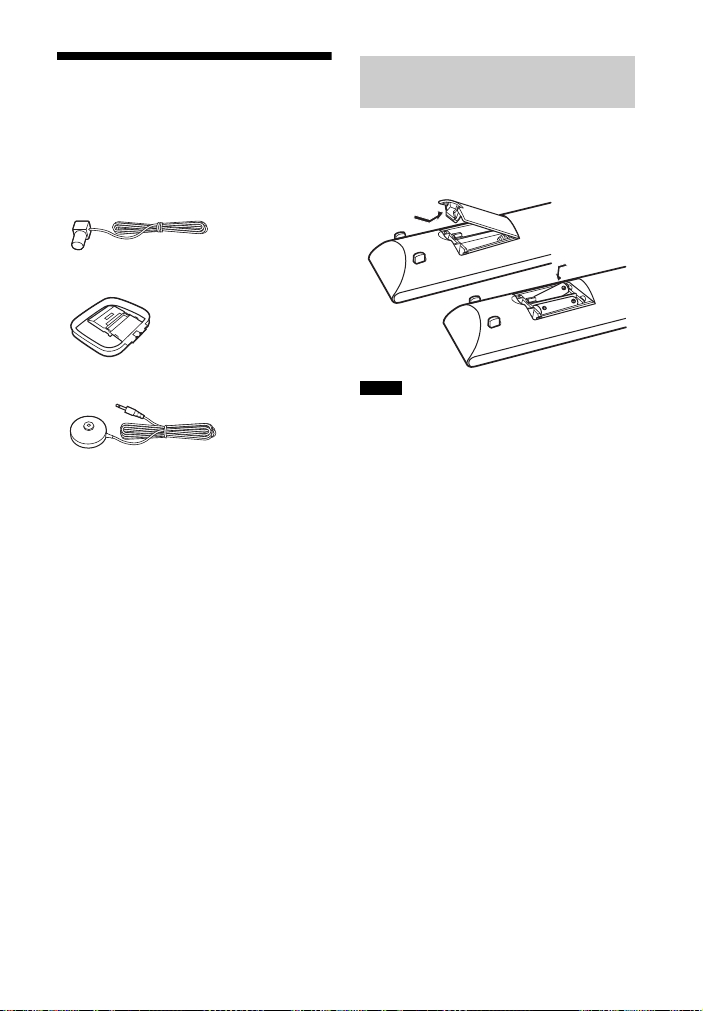
Supplied accessories
• Operating Instructions (this manual)
• Quick Setup Guide (1)
• Remote control (RM-AAP102) (1)
• R6 (size AA) batteries (2)
• FM wire antenna (aerial) (1)
• AM loop antenna (aerial) (1)
Inserting batteries into
the remote control
Insert two R6 (size-AA) batteries
(supplied) in the remote control. Observe
the correct polarity when installing
batteries.
• Optimizer microphone (ECM-AC2) (1)
Notes
• Do not leave the remote control in an extremely
hot or humid place.
• Do not use a new battery with old ones.
• Do not mix m anganese batteries and other kinds
of batteries.
• Do not expose the remote control sensor to
direct sunlight or lighting apparatuses. Doing so
may cause a malfunction.
• If you do not intend to use the remote control for
an extended period of time, remove the batteries
to avoid possible damage from battery leakage
and corrosion.
• When you replace or remove the batteries, the
programmed codes may be cleared. If this
happens, reprogram the remote control
(page 108).
• When the receiver no longer responds to the
remote control, replace all the batteries with
new ones.
US
9
Page 10
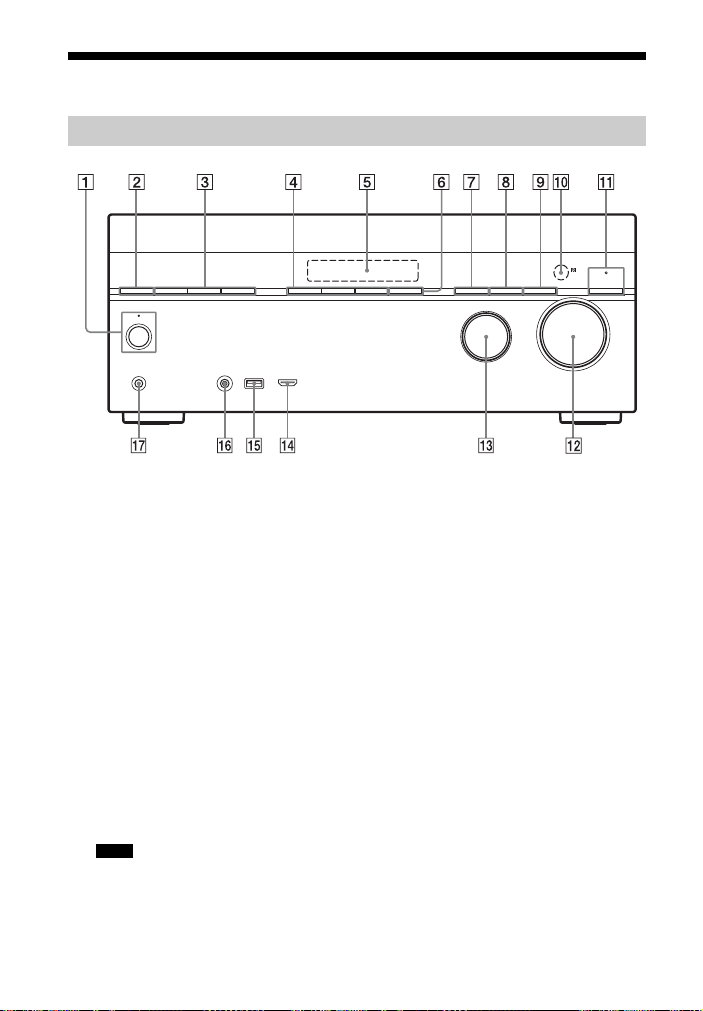
Description and location of parts
Front panel
A ?/1 (on/standby) (page 37, 53, 60,
90)
The indicator above the button lights
up as follows:
Green: The receiver is turned on.
Amber: The receiver is in standby
mode, and
– Either “Control for HDMI”
(page 99), “Network Standby”
(page 101), or “Bluetooth Standby”
(page 81) is set to “On”.
– “Pass Through” is set to “On” or
“Auto” (page 99).
– The receiver in zone 2 is turned on
(page 89).
Lights off when the receiver is in
standby mode and “Control for
HDMI”, “Pass Through”, “Network
Standby”, and “Bluetooth Standby”
are set to “Off”.
Note
If the indicator flashes slowly, the software
update is in progress (page 75).
B SPEAKERS (page 39)
US
10
C TUNING MODE, TUNING +/–
Press TUNING MODE to operate a
tuner (FM/AM).
Press TUNING +/– to scan a station.
D A.F.D./2CH, MOVIE, MUSIC (page
46, 55, 60)
E Display panel (page 12)
F SOUND OPTIMIZER (page 59)
G BLUETOOTH (page 78)
Operates the Bluetooth function.
H DIMMER
Adjusts the brightness of the display
panel in 3 levels.
I DISPLAY (page 107)
J Remote control sensor
Receives signals from remote control.
K PURE DIRECT (page 59)
The indicator above the button lights
up when Pure Direct function is
activated.
L MASTER VOLUME (page 46, 97)
M INPUT SELECTOR (page 39, 46, 86)
Page 11

N HDMI/MHL (VIDEO 2 IN) jack
(page 32)
O (USB) port (page 34)
P AUTO CAL MIC jack
Q PHONES jack
Connects to headphones.
11
US
Page 12
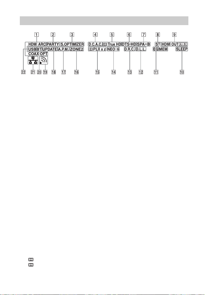
Indicators on the display panel
A Input indicator
Lights up to indicate the current input.
HDMI
The receiver recognizes the equipment
connected via an HDMI IN jack.
ARC
TV input is selected and the Audio
Return Channel (ARC) signals are
detected.
COAX
Digital signal is input through the
COAXIAL jack (page 86).
OPT
Digital signal is input through the
OPTICAL jack (page 86).
B PARTY
Lights up when PARTY
STREAMING function is activated
(page 72).
C S.OPTIMIZER
Lights up when Sound Optimizer
function is activated (page 59).
D D.C.A.C.
Lights up when the measurement
results of the “Auto Calibration”
function are applied.
E Dolby Digital Surround indicator*
Lights up the respective indicator
when the receiver is decoding the
corresponding Dolby Digital format
signals.
TrueHD
Dolby Digital
Dolby TrueHD
F DTS(-HD) indicator*
Lights up the respective indicator
when the receiver is decoding the
corresponding DTS format signals.
DTS
DTS-HD
G Speaker system indicator
(page 39)
H Tuning indicator
ST
DTS
DTS-HD
Lights up when the receiver tunes to a
stereo broadcast.
MEM
Lights up when memory function, such
as Preset Memory (page 54), etc., is
activated.
I HDMI OUT A + B (page 85)
J SLEEP
Lights up when the Sleep Timer is
activated (page 16).
K EQ
Lights up when the equalizer is
activated.
L D.L.L.
Lights up when the Digital Legato
Linear (D.L.L.) function is activated
(page 97).
M D.R.C.
Lights up when dynamic range
compression is activated (page 99).
12
US
Page 13

N NEO:6
Lights up when DTS Neo:6 Cinema/
Music decoding is activated (page 56,
57).
O Dolby Pro Logic indicator
Lights up the respective indicator
when the receiver performs Dolby Pro
Logic processing. This matrix
surround decoding technology can
enhance input signals.
PL
PLII
PLIIx
PLIIz
Note
These indicators may not light up depending
on the speaker pattern setting.
P ZONE 2
Dolby Pro Logic
Dolby Pro Logic II
Dolby Pro Logic IIx
Dolby Pro Logic IIz
Lights up while operation in zone 2 is
being enabled.
Q A.P.M.
Lights up when the A .P.M. (Automatic
Phase Matching) function is activated.
You can only set the A.P.M. function
in the DCAC (Digital Cinema Auto
Calibration) function (page 95).
R UPDATE
Lights up when a new software is
available (page 75).
S Wireless LAN signal strength
indicator
Lights up to show the strength of the
wireless LAN signal (page 41, 42).
No signal.
The signal strength is weak.
The signal strength is
moderate.
The signal strength is strong.
T BT
Lights up when Bl uetooth device is
connected (page 80).
U Wired LAN indicator
Lights up when LAN cable is
connected.
V USB
Lights up when iPod/iPhone or USB
device is detected.
* When playing a Dolby Digital or DTS format
disc, make sure that you have completed the
digital connections and that INPUT MODE is
not set to “ANALOG” (page 86) or “2ch
Analog Direct” is not selected.
13
US
Page 14
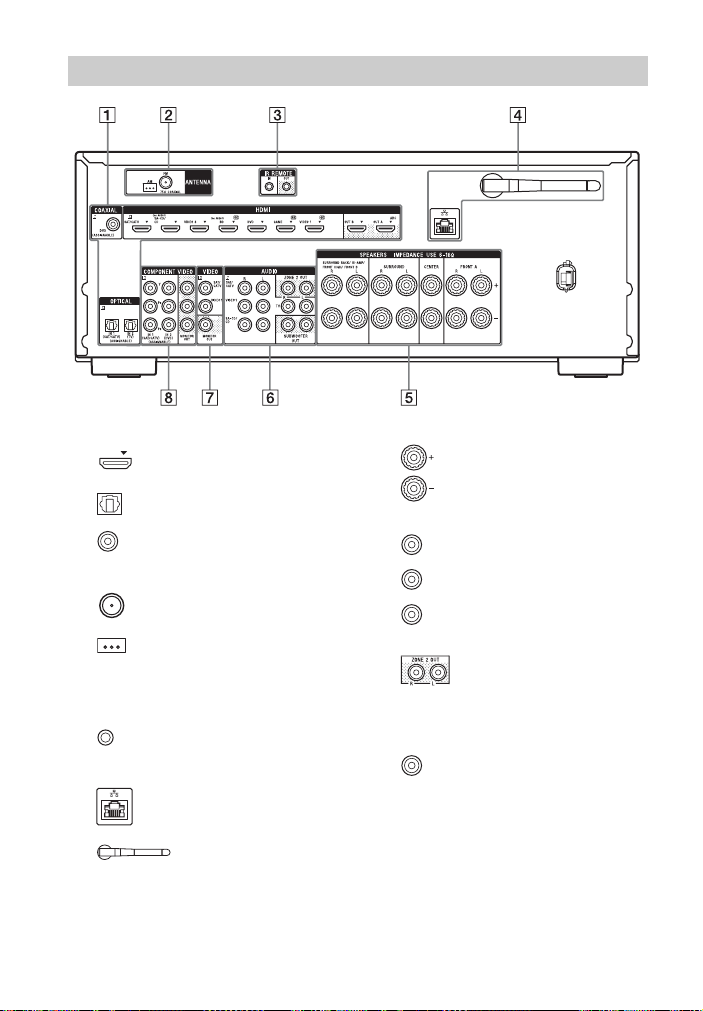
Rear panel
A DIGITAL INPUT/OUTPUT section
HDMI IN/OUT* jacks (page
28, 31)
OPTICAL IN jacks (page 28,
33)
COAXIAL IN jack (page 33)
B TUNER section
FM ANTENNA jack
(page 34)
AM ANTENNA terminals
(page 34)
C Controls jacks for Sony equipment
and other external equipment
IR REMOTE IN/OUT jacks
(page 88)
D NETWORK section
LAN port** (page 36)
Wireless LAN antenna
(page 36)
US
14
E SPEAKERS section (page 26)
F AUDIO INPUT/OUTPUT section
White (L)
Red (R)
Black
AUDIO IN jacks
(page 33)
SUBWOOFER OUT
jacks (page 26)
ZONE 2 OUT jacks
(page 88)
G VIDEO INPUT/OUTPUT section
(page 28, 33)
Yellow
VIDEO IN/OUT*
jacks
Page 15
H COMPONENT VIDEO INPUT/
OUTPUT section (page 28, 33)
Green (Y)
Blue (P
Red (PR)
* You must connect the HDMI OUT or
MONITOR OUT jack to your TV to watch the
selected input image (page 28).
** You can also use this port for maintenance and
service (page 101).
Y, PB, PR IN/OUT*
B)
jacks
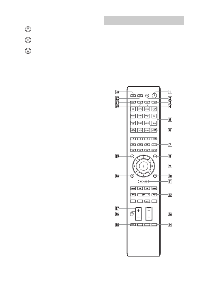
Remote control
Use the supplied remote control to operate
this receiver and other equipment. The
remote control is pre-programmed to
operate Sony audio/video equipment. You
can also program the remote control to
operate non-Sony equipment. For details,
see “Programming the remote control”
(page 108).
RM-AAP102
15
US
Page 16

A ?/1 (on/standby)
Turns the receiver on or sets it to the
standby mode.
If you press ZONE (
T) to switch the
remote control to zone 2 mode, you
can turn the power for zone 2 on or off
using ?/1 (page 89).
Saving the power in standby mode
When “Control for HDMI”, “Pass
Through”, “Network Standby”, and
“Bluetooth Standby” are set to “Off”,
and the receiver in zone 2 is turned off.
B AV ?/1
1)
(on/standby)
Turns on or off the audio/video
equipment that the remote control is
programmed to operate.
To tu rn t he TV o n o r of f, pr es s TV (
and then press AV ?/1.
Note
The function of the AV ?/1 changes
automatically each time you press the input
buttons (E).
C SLEEP
Press AMP (4), then press SLEEP to
set the receiver to turn off
automatically at specified time.
Each time you press SLEEP, the
display changes cyclically as follows:
0:30:00 t 1:00:00 t 1:30:00 t
2:00:00 t OFF
Tips
• To check the remaining time before the
receiver turns off, press SLEEP. The
remaining time appears on the display
panel.
• The Sleep Timer will be canceled when
you perform the following.
– Press SLEEP again.
–Update the software of the receiver.
–Press ?/1.
TV INPUT
Press TV (U), then press TV INPUT
to select the input signal (TV input or
video input).
D AMP
Activates the receiver operation for
main zone (page 107).
E Input buttons2)
Selects the equipment you want to use.
When you press any of the input
buttons, the receiver turns on. The
input buttons are pre-assigned to
automatically control Sony equipment
when you select them. You can also
program the remote control to control
non-Sony equipment following the
steps in “Programming the remote
control” on page 108.
F HDMI OUTPUT (page 85)
G Numeric/text buttons
Press to
– preset/tune to the preset stations
(page 54).
U)
– select track numbers. Press 0/10 to
select track number 10.
– select channel numbers.
– select the letters (ABC, DEF, etc.).
– select @ for the punctuation marks
(!, ?, etc.) or other symbols (#, %,
etc.) when you enter characters for
network features.
Press TV (
buttons to select the TV channels.
1)
ENT
Enters the value after selecting a
channel, disc, or track using numeric
buttons.
CHARACTER
Selects the character type for network
features.
Each time you press CHARACTER,
the character type changes in sequence
as follows:
“abc” (lowercase letters) t “ABC”
(uppercase letters) t “123”
(numbers)
1)
CLR
Press to
– erase a letter for network features.
– clear a mistake when you press the
incorrect numeric/text button.
1)
-/--
Selects channel entry mode, either one
or two digit.
1)2)
U), then press the numeric
16
US
Page 17

Press TV (U), then press -/-- to select
the TV channel entry mode.
1)
>10
Selects track numbers over 10.
INPUT MODE (page 86)
H AMP MENU
Displays the menu to operate the
receiver (page 102).
1)
I
,
Press V/v/B/b to select the menu
V/v/B/b
1)
items, then press to enter/confirm
the selection.
J OPTIONS
1)
Displays and selects items from the
options menus.
Press TV (
display the TV function options.
K HOME
U), then press OPTIONS to
1)
Displays the menu of the audio/video
equipment that is currently being
controlled by the remote control.
For example, press AMP (
4), then
press HOME to display the home
menu (page 44).
Press the input buttons (
E), then press
HOME to display the menu of the
equipment that you want to control.
L ./>1), m/M1), N
1)
x
Skip, backward/forward, play, pause,
stop operation.
PRESET +/–
1)
Selects preset stations or channels.
TUNING +/–
Scans a station.
D.TUNING
2)
Enters direct tuning mode.
PARTY START/CLOSE
Starts or closes a PARTY (page 72).
PARTY JOIN/LEAVE
Joins or leaves a PARTY (page 73).
1
GUIDE
Press TV (U), then press GUIDE to
display the on-screen program guide.
1)2)
, X1),
REPEAT
1)
Plays a track or a folder repeatedly.
SHUFFLE
1)
Plays a track or a folder in random
order.
M TV CH +/–
1)2)
Press TV (U), then press TV CH +/–
to scan for the preset TV channels.
SOUND FIELD +/–
2)
Selects a sound field (page 55).
N ALPHABET SEARCH
Searches for an item using a keyword
(page 77).
ALPHABET PREVIOUS
Searches for previous item.
ALPHABET NEXT
Searches for next item.
PREVIEW (HDMI)
Selects the “Preview for HDMI”
function.
Turns on a live picture-in-picture
preview of HDMI inputs connected to
this receiver.
Press V/v repeatedly to select each
HDMI input preview, then press to
enter/confirm the selection.
(This feature is powered by Silicon
Image InstaPrevue
Note
The “Preview for HDMI” function is
available for HDMI BD, DVD, GAME, and
VIDEO 2 input.
Tips
• This function does not work in the
following cases:
– The equipment is not connected to the
HDMI input jack.
– The equipment connected to the
supported HDMI input jack is not turned
on.
– The current input is not HDMI input.
– When “Fast View” is set to “Off”.
– When an unsupported HDMI video
format (480i, 576i, 4K, some 3D video
signal, some video camera signal or
VGA signal) is input.
TM
technology)
17
US
Page 18

• The picture-in-picture preview will be
blacked out when 4K or some 3D video
signal is input.
TOP MENU
1)
Opens or closes the BD-ROM’s or
DVD’s Top Menu.
POP UP/MENU
1)
Opens or closes the BD-ROM’s Popup Menu, or the DVD’s menu.
O iPhone CTRL
Enters iPod/iPhone control mode when
using iPod/iPhone.
MEMORY
Stores a station during tuner operation.
1)
P
Turns off the sound temporarily. Press
the button again to restore the sound.
Press TV (
U), then press to
activate the TV’s muting function.
Q +/–1)
Adjusts the volume level of all
speakers at the same time.
Press TV (
adjust the TV volume level.
R RETURN O
U), then press +/– to
1)
Returns to the previous menu or exits
the menu while the menu or on-screen
guide is displayed on the TV screen.
Press TV (
U), then press RETURN
O to return to the previous menu of
Sony TV.
S DISPLAY
1)
Views information on the display
panel.
Press TV (
U), then press DISPLAY to
display information of TV.
T ZONE (page 89)
U TV
Changes the remote control button
function to activate the buttons printed
in yellow.
V RM SET UP
Programs the remote control
(page 108).
W PURE DIRECT (page 59)
1)
See the table on page 19 and 20 for information
on the buttons that you can use to control each
equipment.
2)
The VIDEO 2, 5, N/D.TUNING and
TV CH +/SOUND FIELD + buttons have
tactile dots. Use the tactile dots as reference
when operating the receiver.
Notes
• The above explanation is intended to serve as
examples.
• Depending on the model of your connected
equipment, some functions explained in this
section may not work with the supplied remote
control.
18
US
Page 19

To control other Sony equipment
Name TV VCR DVD
B AV ?/1
G Numeric buttons
ENT
CLR
-/--
>10
I V/v/B/b,
J OPTIONS
K HOME
L ./>
PRESET +/–
m/M
N, X, x
GUIDE
REPEAT
SHUFFLE
M TV CH +/–
N TOP MENU, POP UP/
MENU
P
Q +/–
R RETURN O
S DISPLAY
a)
DVD player only.
b)
LD player only.
c)
Video CD player only.
zzzzzzz
zzzzzzz
zzzzzzz
zz
zzzzzz
z zzzz
zzzzzz
zzzzzzz
zzzzzzz
zzzzzzz
zz
z
z
z
z zzzzz
zzzzzzz
player,
DVD/VCR
combo
zz z
zz
zz z
Blu-ray
player
a)
HDD
Disc
Recorder
zzz
PSX Video CD
player,
LD player
b)
c)
z
c)
z
19
US
Page 20

Name Digital
B AV ?/1
G Numeric buttons
ENT
CLR
-/--
>10
I V/v/B/b,
J OPTIONS
K HOME
L ./>
PRESET +/–
m/M
N, X, x
GUIDE
REPEAT
SHUFFLE
M TV CH +/–
N TOP MENU, POP UP/
MENU
P
Q +/–
R RETURN O
S DISPLAY
d)
Deck B only.
CATV
terminal
zzz zz
zzzzzz
zzzzzz
zzz
zz
zzz
zz
zzzz
zzzz
zz
zzz
zzzzd)zz
Digital
DSS
satellite/
terrestrial
receiver
zz
zz
Tape
DAT deck CD
deck
A/B
player,
MD deck
zz
d)
zz
d)
z
zz
z
20
US
Page 21
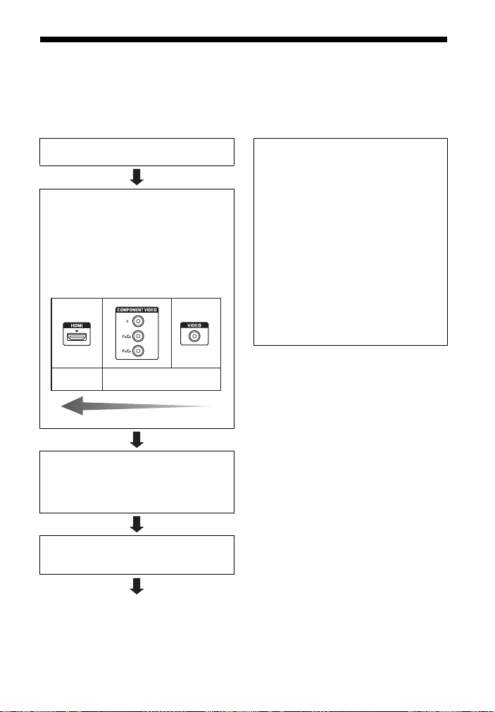
Getting started
You can enjoy your audio/video equipment connected to the receiver by following the
simple steps below.
Before connecting cords, be sure to disconnect the AC power cord (mains lead).
Installing and connecting the speakers
(page 24, 26)
Connecting the TV and other equipment
(page 28, 29)
The image quality depends on the connecting
jack. See the illustration below. Select the
connection according to the jacks on your
equipment.
We recommend that you connect your
equipment via HDMI connection if they have
HDMI jacks.
Digital
High quality image
Preparing the receiver
See “Setting the voltage selector” (page 37),
“Connecting the AC power cord (mains lead)”
(page 37) and “Turning on the receiver”
(page 37).
Setting the receiver
See “Setting up the receiver using the Easy
Setup” (page 37).
Analog
Setting the audio output settings on the
connected equipment
To output multi channel digital audio, check the
digital audio output setting on the connected
equipment.
For a Sony Blu-ray Disc player, check that
“Audio (HDMI)”, “BD Audio MIX Setting”,
“Dolby Digital/DTS”, “Dolby Digital”, and
“DTS” are set to “Auto”, “Off”, “Bitstream”,
“Dolby Digital”, and “DTS” respectively (as of
August 1, 2012).
For a PlayStation 3, after having connected the
receiver with an HDMI cable, select the “Audio
Output Settings” in “Sound Settings”, and
select “HDMI” and “Automatic” (with system
software version 4.21).
For details, refer to the operating instructions
supplied with the connected equipment.
21
US
Page 22
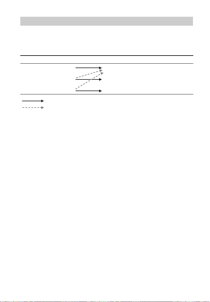
Function for conversion of video signals
The receiver is equipped with a function for converting video signals.
Video signals and component video signals can be output as HDMI video signals. As the
default setting, video signals input from the connected equipment are output as shown in
the table with solid arrows.
INPUT jack OUTPUT jack
HDMI IN
HDMI OUT
COMPONENT VIDEO IN
VIDEO IN
: Same type of signal as that of the input signal is output.
: Video signals are upconverted and output (up to 4K).
Notes on converting video
signals
• When video signals from a VCR, etc., are
upconverted on this receiver and then
viewed on your TV, depending on the
status of the video signal output, the
image on the TV screen may appear
distorted horizontally or no image can be
seen.
• If you are using an image improvement
circuitry with your VCR, it may impact
the video signal conversion. It is
recommended to turn off this function on
your VCR.
• Converted HDMI image output does not
support “x.v.Color (x.v.Colour)”, Deep
Color (Deep Colour), and 3D.
• HDMI video signals cannot be converted
to component video signals and video
signals.
• 1080p component video signals cannot
be upconverted.
COMPONENT VIDEO MONITOR OUT
MONITOR OUT
22
US
Page 23
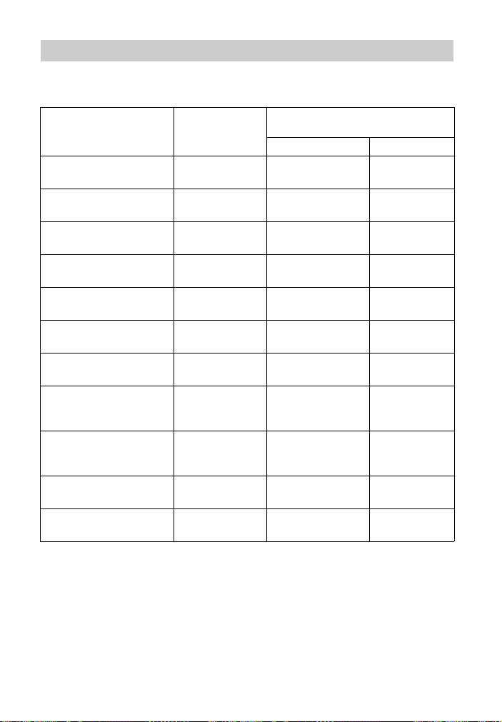
Digital audio formats supported by the receiver
Digital audio formats that this receiver can decode depend on digital audio output jacks of
the equipment connected. This receiver supports the following audio formats.
Audio format
[Display]
Dolby Digital
[DOLBY D]
Dolby Digital EX
[DOLBY D EX]
Dolby Digital Plus
a)
[DOLBY D +]
Dolby TrueHD
a)
[DOLBY HD]
DTS
[DTS]
DTS-ES
[DTS-ES]
DTS 96/24
[DTS 96/24]
DTS-HD
High Resolution Audio
Maximum number
a)
of channels
5.1 aa
6.1 aa
7.1 × a
7.1 × a
5.1 aa
6.1 aa
5.1 aa
7.1 × a
[DTS-HD HR]
DTS-HD
Master Audio
a)b)
7.1 × a
[DTS-HD MA]
a)
DSD
[DSD]
Multi Channel Linear PCM
a)
[PCM]
a)
Audio signals are output in another format if the playback equipment does not correspond to the
format. For details, refer to the operating instructions of the playback equipment.
b)
Signals with a sampling frequency of more than 96 kHz are played back at 96 kHz or 88.2 kHz.
c)
These formats are supported by MHL when you connect a MHL-compatible source device to the
HDMI/MHL (VIDEO 2 IN) jack.
5.1 × a
7.1 × a
Connection between the playback
equipment and the receiver
COAXIAL/OPTICAL HDMI
c)
c)
c)
c)
c)
c)
c)
c)
23
US
Page 24
Connections
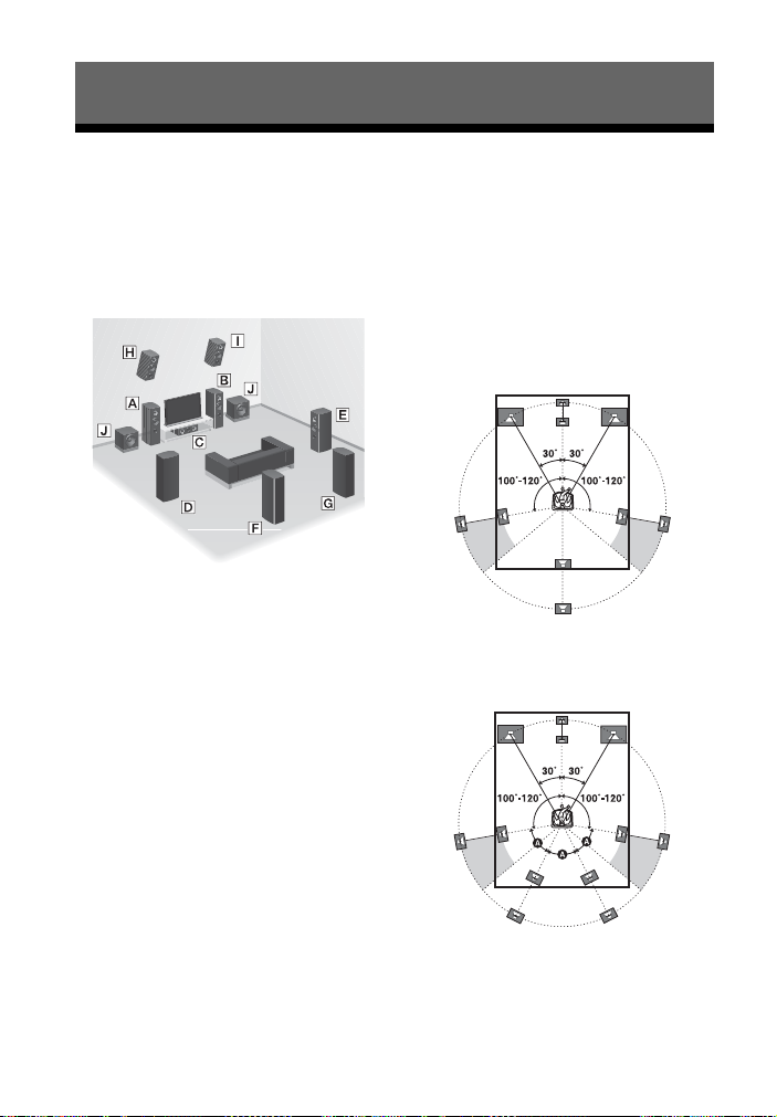
1: Installing the speakers
This receiver allows you to use up to a 7.2
channel system (7 speakers and 2
subwoofers).
Example of speaker system
configuration
A Front speaker (Left)
B Front speaker (Right)
C Center speaker
D Surround speaker (Left)
E Surround speaker (Right)
F Surround back speaker (Left)*
G Surround back speaker (Right)*
H Front high speaker (Left)*
I Front high speaker (Right)*
J Subwoofer
* You cannot use the surround back speakers and
the front high speakers simultaneously.
5.1 channel speaker system
To fully enjoy theater-like multi channel
surround sound requires five speakers (two
front speakers, a center speaker, and two
surround speakers) and a subwoofer.
7.1 channel speaker system
using surround back
speakers
You can enjoy high fidelity reproduction of
DVD or Blu-ray Disc software recorded
sound in 6.1 channel or 7.1 channel format.
• 6.1 channel speaker placement
Place the surround back speaker behind
the listening position.
• 7.1 channel speaker placement
Place the surround back speakers as
shown in the illustration below . The angle
A should be the same.
24
US
Page 25
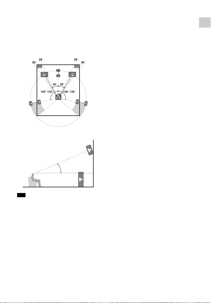
7.1 channel speaker system
using front high speakers
You can enjoy vertical sound effects by
connecting additional two front high
speakers.
Place the front high speakers
– at an angle between 25° to 35°.
– at an angle of 20° ± 5° in height.
20˚ ± 5˚
Connections
Tip
Since the subwoofer does not emit highly
directional signals, you can place it wherever you
want.
25
US
Page 26
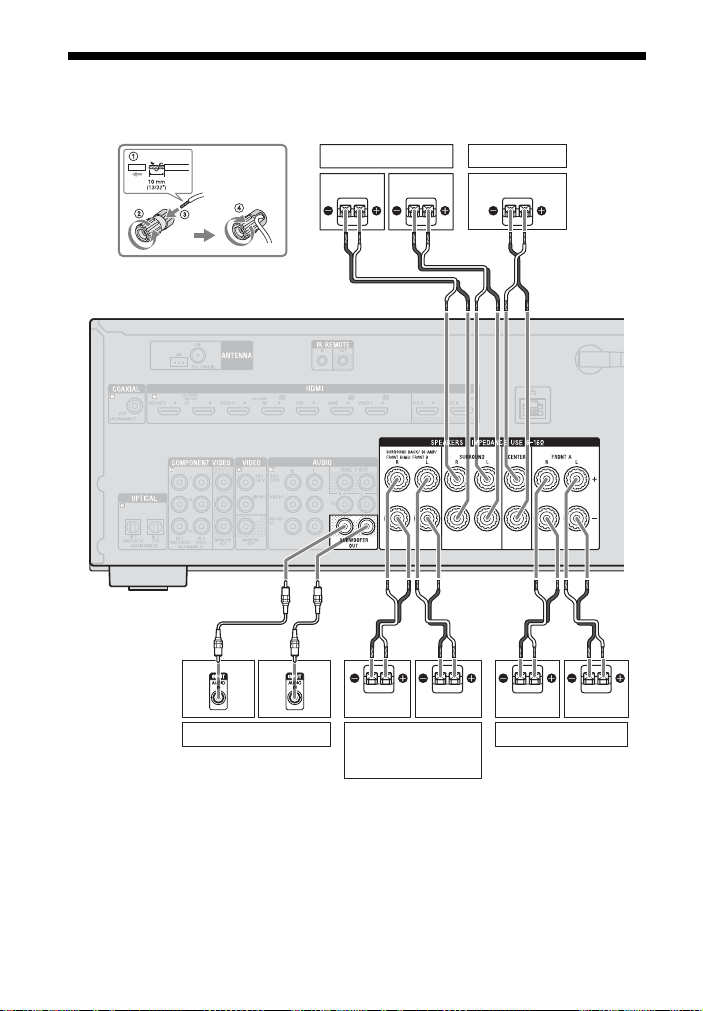
2: Connecting the speakers
Before connecting cords, be sure to disconnect the AC power cord (mains lead).
Surround speaker
Right Left
Center speaker
A
A
Subwoofer *
A Monaural audio cord (not supplied)
B Speaker cord (not supplied)
B
B
Right
Surround back/
Bi-amplifier/Front high/
Front B speaker
Left
**
B
B
Right Left
Front A speaker
26
US
Page 27
* When you connect a subwoofer with an auto
standby function, turn off the function when
watching movies. If the auto standby fun ction
is set to on, it turns to standby mode
automatically based on the level of the input
signal to the subwoofer, and the sound may
not be output.
** Notes on the SPEAKERS SURROUND
BACK/BI-AMP/FRONT HIGH/FRONT B
terminals connection.
– If you connect only one surround back
speaker, connect it to L of this terminals.
– If you have an additional front speaker
system, connect them to this terminals.
Set the assignment for the SPEAKERS
SURROUND BACK/BI-AMP/FRONT
HIGH/FRONT B terminals to “Front B
Speakers” by using the “Speaker
Connection” in the Speaker Settings menu
(page 95). You can select the front speaker
system you want by using the SPEAKERS
button on the receiver (page 39).
– You can connect the front speakers to this
terminals using bi-amplifier connection
(page 27).
Set the assignment for the SPEAKERS
SURROUND BACK/BI-AMP/FRONT
HIGH/FRONT B terminals to “BiAmplifier Connection” by using the
“Speaker Connection” in the Speaker
Settings menu (page 95).
Note
After you have installed and connected your
speaker, be sure to select the speaker pattern you
want using the “Speaker Connection” in the
Speaker Settings menu (page 95).
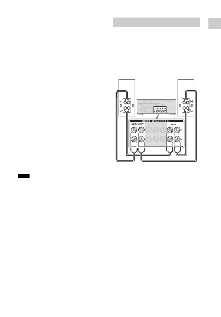
Bi-amplifier connection
If you are not using surround back speakers
and front high speakers, you can connect
the front speakers to the SPEAKERS
SURROUND BACK/BI-AMP/FRONT
HIGH/FRONT B terminals using a biamplifier connection.
Front speaker
(Right)
Connect the jacks on the Lo (or Hi) side of
the front speakers to the SPEAKERS
FRONT A terminals, and connect the jacks
on the Hi (or Lo) side of the front speakers
to the SPEAKERS SURROUND BACK/
BI-AMP/FRONT HIGH/FRONT B
terminals.
Make sure that metal fittings of Hi/Lo
attached to the speakers have been removed
from the speakers to avoid receiver
malfunction.
After you have made the bi-amplifier
connection, set the assignment for the
SPEAKERS SURROUND BACK/BIAMP/FRONT HIGH/FRONT B terminals
“Bi-Amplifier Connection” by using the
to
“Speaker Connection” in the Speaker
Settings menu (page 95).
Front speaker
(Left)
Connections
27
US
Page 28
3: Connecting the TV
You can watch the selected input image when you connect the HDMI OUT or MONITOR
OUT jack to a TV. You can operate this receiver using a GUI (Graphical User Interface).
GUI is only for HDMI OUT A and HDMI OUT B.
Before connecting cords, be sure to disconnect the AC power cord (mains lead).
TV
Audio signalsVideo signals
oror
Audio/Video
signals
A
BC** D** E*
A Component video cord (not supplied)
B Video cord (not supplied)
C Audio cord (not supplied)
D Optical digital cord (not supplied)
E HDMI cable (not supplied)
Sony recommends that you use an
HDMI-authorized cable or Sony HDMI
cable.
Recommended connection
Alternative connection
28
US
Page 29

To enjoy the TV broadcast
in multi channel surround
sound from the receiver
* If your TV is compatible with the Audio Return
Channel (ARC) function, connect E.
Be sure to set the “Control for HDMI” to “On”
in HDMI Settings menu (page 82). If you want
to select an audio signal using other than an
HDMI cable (e.g., via an optical digital cord or
an audio cord), switch the audio input mode
using INPUT MODE (page 86).
**If your TV is not compatible with the ARC
function, connect C or D.
Be sure to turn off the TV’s volume or
activate the TV’s muting function.
Notes
• Connect a TV monitor or a projector to the
HDMI OUT or MONITOR OUT jack on the
receiver.
• Depending on the status of the connection
between the TV and the antenna (aerial), the
image on the TV screen may be distorted. If this
is the case, place the antenna (aerial) farther
away from the receiver.
• When connecting optical digital cords, insert the
plugs straight until they click into place.
• Do not bend or tie optical digital cords.
Tips
• All the digital audio jacks are compatible with
32 kHz, 44.1 kHz, 48 kHz, and 96 kHz sampling
frequencies.
• The receiver has a video conversion function.
For details, see “Function for conversion of
video signals” (page 22).
• When you connect the audio output jack of the
TV to the TV IN jacks of the receiver to output
the TV sound from the speakers connected to
the receiver, set the sound output jack of the TV
to “Fixed” if it can be switched between either
“Fixed” or “Variable”.
To listen to the sound from
the TV
If your TV does not support System Audio
Control function, set the “Audio Out” to
“TV+AMP” in the HDMI Settings menu
(page 99).
4: Connecting other equipment
Using HDMI connection
High-Definition Multimedia Interface
(HDMI) is an interface which transmits
video and audio signals in digital format.
By connecting Sony “BRAVIA” Synccompatible equipment using HDMI cables,
operations can be simplified. See
““BRAVIA” Sync Features” (page 82).
HDMI features
• A digital audio signals transmitted by
HDMI can be output from the speakers
connected to the receiver. This signal
supports Dolby Digital, DTS, DSD, and
Linear PCM. For details, see “Digital
audio formats supported by the receiver”
(page 23).
• The receiver can receive Multi Channel
Linear PCM (up to 8 channels) with a
sampling frequency of 192 kHz or less
with an HDMI connection.
• Analog video signals input to the
receiver’s VIDEO jack or
COMPONENT VIDEO jacks can be
output as HDMI signals (page 22). Audio
signals are not output from an HDMI
OUT jacks while the image is being
converted.
• This receiver supports High Bitrate
Audio (DTS-HD Master Audio, Dolby
TrueHD), Deep Color (Deep Colour),
“x.v.Color (x.v.Colour)”, and 4K or 3D
transmission.
• To enjoy 3D images, connect 3Dcompatible TV and video equipment
(Blu-ray Disc player, Blu-ray Disc
recorder, PlayStation 3, etc.) to the
receiver using High Speed HDMI cables,
put on 3D glasses, and then play back a
3D-compatible content.
Connections
29
US
Page 30

• To enjoy 4K (HDMI BD, GAME and
VIDEO 1 input) images, connect 4Kcompatible TV and video equipment
(Blu-ray Disc player, etc) to the receiver
using High Speed HDMI cables, and then
play back a 4K-compatible content.
• You can view HDMI BD, DVD, GAME,
and VIDEO 2 input on picture-in-picture
preview.
Notes on HDMI connections
• Depending on the TV or the video
equipment, 4K or 3D images may not be
displayed. Check the HDMI video
formats supported by the receiver
(page 129).
• Refer to the operating instructions o f each
connected equipment for details.
When connecting cords
• Before connecting cords, be sure to
disconnect the AC power cord (mains
lead).
• It is not necessary to connect all the cords.
Connect according to the availability of
jacks on the connected equipment.
• Use a High Speed HDMI cable. If you use
a Standard HDMI cable, 1080p, Deep
Color (Deep Colour), 4K or 3D images
may not be displayed properly.
• We do not recommend using an HDMIDVI conversio n cable. When you connect
an HDMI-DVI conversion cable to a
DVI-D equipment, the sound and/or the
image may be lost. Connect a separate
audio cords or digital connecting cords,
then reassign the input jacks when the
sound is not output correctly. For details,
see “Using other video/audio input jacks
(Input Assign)” (page 86).
• When connecting optical digital cords,
insert the plugs straight until they click
into place.
• Do not bend or tie optical digital cords.
Tip
All the digital audio jacks are compatible with
32 kHz, 44.1 kHz, 48 kHz, and 96 kHz sampling
frequencies.
If you want to connect
several digital equipment,
but cannot find an unused
input
See “Using other video/audio input jacks
(Input Assign)” (page 86).
Converting video signals
This receiver is equipped with a function
for converting video signals. For details,
see “Function for conversion of video
signals” (page 22).
30
US
Page 31

Connecting equipment with HDMI jacks
If your equipment does not have an HDMI jack, see page 33.
Connections
Video game DVD player PlayStation 3
Audio/video
signals
Blu-ray Disc
player
Audio/video
signals
Audio/video
signals
Audio/video
signals
VCR, DVD
recorder
Audio/video
signals
AAAAA
A
Audio/video
signals
Satellite tuner,
cable TV tuner
A
Audio/video
signals
Super Audio CD
player, CD player
A HDMI cable (not supplied)
Sony recommends that you use an
HDMI-authorized cable or Sony
HDMI cable.
31
US
Page 32

Notes
• This HDMI connection is an example.
You can connect each HDMI equipment to any
HDMI inputs, including HDMI input on the
front panel.
• SA-CD/CD and BD inputs have better sound
quality. When you need a higher sound quality,
connect your equipment to these jacks and
select them as input.
• Be sur e to change the default setting of the inp ut
button on the remote control so that you can use
the button to control the connected equipment.
For details, see “Programming the remote
control” (page 108).
• You can rename the input so that it can be
displayed on the receiver’s display panel. For
details, see “Name” in Input Settings menu
(page 100).
Using MHL connection
What is MHL?
MHL (Mobile High-Definition Link) is an
HD video and digital audio interface for
connecting mobile phones and portable
devices to HDTVs and other home
entertainment products. MHL can support
1080p HD video and digital audio signals
and supply power to the mobile device
simultaneously. It also enables the remote
of TV or other home entertainment
products to control the mobile phone and
access its contents (page 85).
Connecting a MHL- (Mobile
High-Definition Link)
compatible mobile device
for audio/video contents
This receiver incorporates MHL 2
technology.
or
A
B
A MHL cable (not supplied)
Use MHL2-compliant cable.
Sony recommends that you use Sony
MHL cable.
B MHL Direct Attach Device (not supplied)
Notes
• The MHL-compatible mobile device is charged
when connected to the HDMI/MHL (VIDEO 2
IN) jack of the receiver while the receiver is
turned on.
• You can rename the VIDEO 2 input so that it
can be displayed on the receiver’s display panel.
For details, see “Name” in Input Settings menu
(page 100).
32
US
Page 33

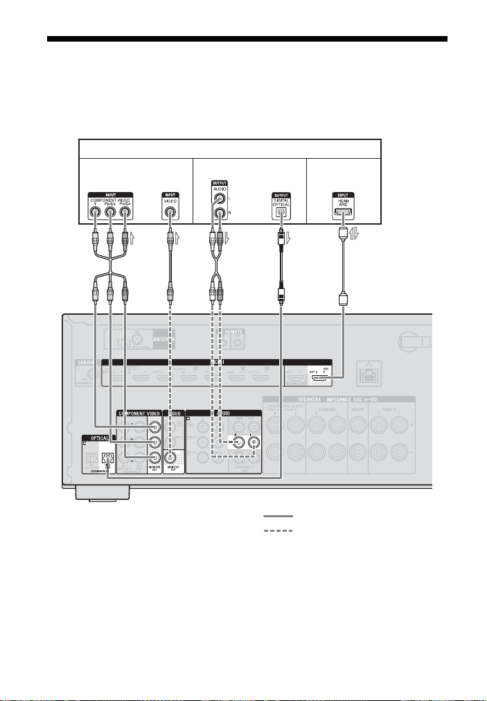
Connecting equipment with jacks other than HDMI
jacks
Connections
Satellite tuner, cable TV tuner
Audio signals
or
Video signals Video signalsAudio signals
or
VCR, DVD recorder, Camcorder,
Video game
ABC D B D
EA C
Audio signals Video signals
*
or
DVD player
B
Audio signals
Super Audio CD
player, CD player
33
US
Page 34

A Optical digital cord (not supplied)
B Audio cord (not supplied)
C Component video cord (not supplied)
D Video cord (not supplied)
E Coaxial digital cord (not supplied)
Recommended connection
Alternative connection
* When you connect equipment with an
OPTICAL jack, reassign the input jacks. For
details, see “Using other video/audio input
jacks (Input Assign)” (page 86).
Notes
• Be sure to change the default setting of the
VIDEO 1 input button on the remote control so
that you can use the button to control your DV D
recorder. For details, see “Programming the
remote control” (page 108).
• You can rename the VIDEO 1 input so that it
can be displayed on the receiver’s display panel.
For details, see “Name” in Input Settings menu
(page 100).
Connecting an iPod, iPhone,
USB device
A
5: Connecting the antennas (aerials)
Before connecting the antennas (aerials),
be sure to disconnect the AC power cord
(mains lead).
AM loop antenna (aerial)
(supplied)
Notes
• To prevent noise pickup, keep the AM loop
antenna (aerial) away from the receiver and
other equipment.
• Be sure to fully extend the FM wire antenna
(aerial).
• After connecting the FM wire antenna (aerial),
keep it as horizontal as possible.
FM wire antenna (aerial)
(supplied)
iPod, iPhone,
USB device
A USB cable (not supplied)
US
34
Page 35

6: Connecting to the network
If you have an Internet connection, you can
connect this receiver to the Internet as well.
You can connect through a wireless or a
wired LAN connection.
System requirements
The following system environment is
required to use the network function of the
receiver.
A Broadband line
connection
A Broadband line connection to the
Internet is required in order to listen to
Sony Entertainment Network (SEN) and to
update the software of the receiver.
Modem
This is the device that is connected to the
broadband line to communicate with the
Internet. Some of these devices are
integrated with the router.
Router
• Use a router compatible with 100 Mbps
or greater transmission speeds to enjoy
content on your home network.
• We recommend that you use a router
equipped with the built-in DHCP
(Dynamic Host Configuration Protocol)
server.
This function automatically assigns IP
addresses on the LAN.
• Use a wireless LAN router/access point if
you want to use a wireless LAN
connection.
LAN cable (CAT5) (For a
wired LAN connection only)
• We recommend that you use this type of
cable for a wired LAN.
Some flat-type LAN cables are easily
affected by noise. We recommend that
you use normal-type cables.
• If the receiver is used in an environment
in which there is power supply noise from
electric products or in a noisy network
environment, use a shielded-type LAN
cable.
Server
A server is a device which delivers content
(music, photos, and videos) to a DLNA
device on a home network. A device that
can be used as a server (a computer, etc.)
must be connected to your wireless or
wired LAN home network*.
* For details on servers which are compatible
with this receiver, see page 61.
Connections
35
US
Page 36

Configuration example
The following illustration is a configuration example of a home network with the receiver
and a server.
We recommend that you connect the server to the router with a wired connection.
Internet Modem
Router
(not supplied)
A For a wired LAN connection only.
B For a wireless LAN connection only.
Be sure to use a wireless LAN router/access
point.
Note
An audio playback on a server may occasionally
be interrupted when you use a wireless
connection.
LAN cable
LAN cable
(not supplied)
Server
36
US
Page 37

Preparing the Receiver
1
Turning on the receiver
Setting the voltage selector
If your receiver has a voltage selector on
the rear panel, check that the voltage
selector is set to the local power supply
voltage. If not, use a screwdriver to set the
selector to the correct position before
connecting the AC power cor d (mains lead)
to a wall outlet.
Depending on the area, the VOLTAGE
SELECTOR may differ.
Connecting the AC power cord (mains lead)
Connect the AC power cord (mains lead) to
a wall outlet.
AC power cord (mains lead)
?/
Press ?/1 to turn on the receiver.
You can also turn on the receiver using ?/1
button on the remote control. When you
turn off the receiver, press
“STANDBY” flashes on the display panel.
Do not disconnect the AC power cord
(mains lead) while “STANDBY” is
flashing. This may cause a malfunction.
?/1 again.
Setting up the receiver using the Easy Setup
You can set the basic settings of the
receiver easily by operating the receiver in
accordance with the instructions on the TV
screen.
Switch the input of the TV to the input
which the receiver is connected.
When you turn on the receiver for the first
time or after the receiver is initialized, the
Easy Setup screen appears on the TV
screen. Proceed to set up the receiver in
accordance with the instructions on the
Easy Setup screen.
You can set up the following functions
using the Easy Setup.
– Speaker Settings
– Network Settings
Preparing the Receiver
To the wall outlet
37
US
Page 38

Notes on Speaker
Settings (Auto
Calibration)
This receiver is equipped with DCAC
(Digital Cinema Auto Calibration) function
which allows you to perform automatic
calibration as follows:
• Check the connection between each
speaker and the receiver.
• Adjust the speaker level.
• Measure the distance of each speaker
from your seating position.
• Measure the speaker size.
• Measure the frequency characteristics
1)
(EQ).
• Measure the frequency characteristics
1)
2)
1)2)
(Phase).
The measurement result is not utilized when
“2ch Analog Direct” is selected.
The measurement result is not utilized when
Dolby TrueHD or DTS-HD signals with a
sampling frequency of more than 48 kHz are
being received.
The DCAC is designed to achieve proper
sound balance for your room. However,
you can adjust the speaker levels manually
according to your preference. For details,
see “Test Tone” (page 97).
Before you perform Auto
Calibration
Before you perform Auto Calibration,
check the following items.
• Set up and connect the speakers (page 24 ,
26).
• Connect only the supplied optimizer
microphone to the AUTO CAL MIC jack.
Do not connect any other microphones to
this jack.
• Set the assignment for the SPEAKERS
SURROUND BACK/BI-AMP/FRONT
HIGH/FRONT B terminals to “BiAmplifier Connection” by using the
“Speaker Connection” in the Speaker
Settings menu if you use bi-amplifier
connection (page 95).
1)
1)
• Set the assignment for the SPEAKERS
SURROUND BACK/BI-AMP/FRONT
HIGH/FRONT B terminals to “Front B
Speakers” by using the “Speaker
Connection” in the Speaker Settings
menu if you use speakers front B
connection (page 95).
• Make sure the speaker output is not set to
“SPK OFF” (page 39).
• Make sure that you are not using PARTY
STREAMING function (page 72).
• Disconnect the headphones.
• Remove any obstacles in the path
between the optimizer microphone and
the speakers to avoid measurement
errors.
• Get accurate measurement by making
sure the environment is free from noise
and quiet.
Notes
• The speakers emit very loud sound during the
calibration and the volume cannot be adjusted.
Provide consideration to your neighborhood and
to the children in presence.
• If the muting function has been activated before
you perform Auto Calibration, the muting
function will shut off automatically.
• The correct measurements may not be able to
take or Auto Calibration cannot be performed
when special speakers, such as dipole speakers
are used.
Confirm active subwoofer
setup
• When a subwoofer is connected, turn on
the subwoofer and turn up the volume
prior to activating the subwoofer. Turn
the LEVEL to just before the mid-point.
• If you connect a subwoofer with a
crossover frequency function, set the
value to maximum.
• If you connect a subwoofer with an auto
standby function, set it to off
(deactivated).
38
US
Page 39

Note
Depending on the characteristics of the
subwoofer you are using, the setup distance value
may be different from the actual position.
To select the front speakers
You can select the front speakers you want
to drive.
Be sure to use the buttons on the receiver to
perform this operation.
SPEAKERS
Press SPEAKERS repeatedly to select
the front speaker system you want to
drive.
You can confirm the selected speakers
terminals by checking the indicators on the
display panel.
Indicators Selected speakers
SP A The speakers connected to the
SP B* The speakers connected to the
SP A+B* The speakers connected to
SPEAKERS FRONT A
terminals.
SPEAKERS SURROUND
BACK/BI-AMP/FRONT
HIGH/ FRONT B terminals.
both the SPEAKERS FRONT
A and SPEAKERS
SURROUND BACK/
BI-AMP/FRONT HIGH/
FRONT B terminals (parallel
connection).
“SPK OFF” appears on the
display panel. No audio
signals are output from any
speaker terminals.
* To select “SP B” or “SP A+B”, set the
assignment for the SPEAKERS SURROUND
BACK/BI-AMP/FRONT HIGH/FRONT B
terminals to “Front B Speakers” by using the
“Speaker Connection” in the Speaker Settings
menu (page 95).
Note
This setting is not available when headphones are
connected.
To cancel Auto Calibration
The Auto Calibration function will be
canceled when you perform the following
during the measurement process:
– Press ?/1.
– Press the input buttons on the remote
control or turn the INPUT SELECTOR
on the receiver.
– Press .
– Press SPEAKERS on the receiver.
– Change the volume level.
– Connect the headphones.
To set up the receiver
manually
See “Adjusting Settings” (page 90).
Configuring the network settings of the receiver
The network settings for the receiver must
be set correctly to use the Home Network,
SEN, AirPlay, and PARTY STREAMING
functions.
Using a wireless LAN
connection
There are several connecting methods you
can use to set up a wireless network:
searching for an access point, using a WPS
connecting method (either the push-button
method or the PIN code method), or
manual setting.
Preparing the Receiver
39
US
Page 40

Notes
• Make sure not to use the wireless LAN function
where medical equipment (such as a pacemaker)
is used or where the use of wireless
communication is prohibited.
• Before connecting to your home network, you
need to prepare a wireless LAN router/access
point. For details, refer to the operating
instructions of the device.
• Depending on your home networ k environment,
the wireless LAN router/access point may have
been set up such that it cannot be connected
using WPS, even though it is compatible with
WPS. For details on whether your wireless LAN
router/access point is compatible or not
compatible with WPS, and on the setup of a
WPS connection, refer to the operating
instructions of your wireless LAN router/access
point.
• You may encounter setup difficulties if the
receiver and the wireless LAN router/access
point are located too far from each other. If you
do, move the devices closer to each other.
Searching for an access
point and setting up a
wireless network (Access
Point Scan method)
You can set up a wireless network by
searching for an access point. To set up the
network using this connection method, you
will be required to select or enter the
following information. Check the
following information in advance, and
record it in the space provided below.
The network name (SSID
identifies your network
will be needed in step 7.)
:
If your wireless home network is
secured by encryption, the
security key (WEP key, WPA/
WPA2 key) for your network
(This will be needed in step 8.)
:
* SSID (Service Set Identifier) is a name that
identifies a particular access point.
*
) that
**
. (This
**
.
** This information should be available from a
label on your wireless LAN router/access
point, from the operating instructions, from
the person who set up your wireless network,
or from the information provided by your
Internet service provider.
AMP
DISPLAY
V/v/B/b,
HOME
1 Press AMP, then press HOME.
The home menu is displayed on the TV
screen.
2 Press B/b repeatedly to select
“Settings”, then press .
The Settings menu list appears on the
TV screen.
3 Press V/v/B/b repeatedly to select
“Network”, then press .
4 Press V/v repeatedly to select
“Internet Setting”, then press .
5 Press V/v repeatedly to select
“Wireless”, then press .
6 Press V/v repeatedly to select
“Access Point Scan”, then press
.
The receiver starts searching for access
points, and displays a list of up to 30
available network name (SSID).
7 Press V/v repeatedly to select the
network name (SSID) you want,
then press .
The security setting display appears on
the TV screen.
40
US
Page 41

8 Enter the security key (WEP key,
WPA/WPA2 key) using the onscreen keyboard. Press V/v/B/b
and to select the character one
by one. Then, select “Enter” and
press to confirm the security
key.
“How to acquire the IP Address”
appears on the TV screen.
9 Press V/v repeatedly to select
“Auto”, then press .
When using a fixed IP address
Select “Manual”, then press . The
IP address input display appears on the
TV screen.
Enter the value for “IP Address” using
the on-screen keyboard. Press V/v/B/
b and to select the character one by
one. Then, select “Enter” and press
to confirm the value.
Enter the value for “Subnet Mask”,
“Default Gateway”, “Primary DNS”
and “Secondary DNS”. Then, select
“Next” and press .
10Press V/v repeatedly to select
“Ok”, then press .
“Connecting to the network. Please
wait.” appears on the TV screen.
“Network Settings are now complete
and the receiver has been successfully
connected to the network.” appears
after the network settings are
completed and “ ” lights up on the
display panel. To return to the
Network Settings menu, press .
(Depending on the network
environment, the network settings may
take some time.)
11Perform the server settings.
To listen to audio content stored on the
server, you need to set up your server
(page 61).
Note
If your network has not been secured by
encryption (using the security key), the security
setting display does not appear in step 8.
Tip
When checking the network settings, see
“Information” (page 101).
If you cannot find the
network name (SSID) you
want (manual setup
method)
You can input the network name (SSID)
you want manually if it does not appear on
the list.
1 Select “Manual Registration” in step
6 in “Searching for an access point
and setting up a wireless network
(Access Point Scan method)”
(page 40).
2 Press V/v repeatedly to select
“Direct Input”, then press .
3 Enter the network name (SSID)
using the on-screen keyboard. Press
V/v/B/b and to select a character
one by one. Then, select “Enter” and
press .
The name you entered is registered.
4 Press V/v repeatedly to select the
security setting you want, then press
.
5 Follow steps 8 to 11 in “Searching for
an access point and setting up a
wireless network (Access Point Scan
method)” (page 40).
Setting up a wireless
network using an access
point compliant with WPS
You can easily set up a wireless network
using an access point compliant with WPS.
The WPS setting can be made using either
the push-button configuration method or
the PIN (Personal Identification Number)
code method.
Preparing the Receiver
41
US
Page 42

What is WPS (Wi-Fi
Protected Setup)?
WPS is a standard created by the Wi-Fi
Alliance allowing you to setup a wireless
network easily and securely.
Setting up a wireless
network using the WPS push
button configuration
method
You can easily set up a WPS wireless
connection with one push of the designated
button.
1 Select “WPS Push” in step 6 in
“Searching for an access point and
setting up a wireless network
(Access Point Scan method)”
(page 40).
2 Follow the on-screen instructions,
and press the WPS button on the
access point.
Message: “Push the WPS button on the
access point within 2 minutes.”
WPS button on the
wireless LAN
router/access point
“Network Settings are now complete
and the receiver has been successfully
connected to the network.” appears after
the network settings are complete and
“ ” lights up on the display panel. To
return to the Network Settings menu,
press .
(Depending on the network
environment, the network settings may
take some time.)
3 Perform the server settings.
To listen to audio content stored on the
server, you need to set up your server
(page 61).
Tip
When checking the network settings, see
“Information” (page 101).
Setting up a wireless
network using the WPS PIN
code method
If the access point supports the WPS PIN
(Personal Identification Number) code
connection, you can set up a WPS wireless
connection by entering the receiver’s PIN
code into the wireless LAN router/access
point.
1 Select “Manual Registration” in step
6 in “Searching for an access point
and setting up a wireless network
(Access Point Scan method)”
(page 40).
2 Press V/v repeatedly to select “WPS
PIN”, then press .
The available SSID (access point) list
appears.
Note
SSID that does not support WPS PIN will
appear dimmed and cannot be selected.
3 Press V/v repeatedly to select the
network name (SSID) you want, then
press .
The PIN code (8 digits) of the receiver
appears on the TV screen. Leave the PIN
code displayed until the connection is
complete. (A different PIN code is
displayed each time you perform this
operation.)
4 Input the receiver’s PIN code into the
wireless LAN router/access point.
The receiver starts the network settings.
“Network Settings are now complete
and the receiver has been successfully
connected to the network.” appears after
the network settings are complete and
“” lights up on the display panel. To
return to the Network Settings menu,
press .
(Depending on the network
environment, the network settings may
take some time.)
42
US
Page 43

5 Perform the server settings.
To listen to audio content stored on the
server, you need to set up your server
(page 61).
Tips
• When checking the network settings, see
“Information” (page 101).
• For details on entering the PIN code into the
wireless LAN router/access point, refer to the
operating instructions of the wireless LAN
router/access point.
Using a wired LAN
connection
1 Select “Wired” in step 5 in
“Searching for an access point and
setting up a wireless network
(Access Point Scan method)”
(page 40).
“How to acquire the IP Address”
appears on the TV screen.
2 Press V/v repeatedly to select
“Auto”, then press .
When using a fixed IP address
Select “Manual”, then press . The
IP address input display appears on the
TV screen.
Enter the value for “IP Address” using
the on-screen keyboard. Press V/v/B/
b and to select the character one by
one. Then, select “Enter” and press
to confirm the value.
Enter the value for “Subnet Mask”,
“Default Gateway”, “Primary DNS”
and “Secondary DNS”. Then, select
“Next” and press .
3 Press V/v repeatedly to select
“Ok”, then press .
“Connecting to the network. Please
wait.” appears on the TV screen.
“Network Settings are now complete
and the receiver has been successfully
connected to the network.” appears
after the network settings are
completed. To return to the Network
Settings menu, press . (Depending
on the network environment, the
network settings may take some time.)
4 Perform the server settings.
To listen to audio content stored on the
server, you need to set up your server
(page 61).
Tip
When checking the network settings, see
“Information” (page 101).
Guide to on-screen display operation
You can display the menu of the receiver
on the TV screen and select the function
you want to use on the TV screen by
pressing V/v/B/b and on the remote
control.
When you start operating the receiver,
make sure to press AMP on the remote
control first. Otherwise, operations that
follow may not be aimed at the receiver.
Tip
The AMP button on the remote control lights up
when you press HOME.
Preparing the Receiver
43
US
Page 44

AMP
V/v/B/b,
3 Press B/b repeatedly to select a
menu you want, then press to
enter the menu.
The menu item list appears on the TV
screen.
Example: When you select “Watch”.
RETURN
O
OPTIONS
HOME
Using the menu
1 Switch the input of the TV to the
input which the receiver is
connected.
2 Press AMP, then press HOME.
The home menu is displayed on the TV
screen.
Depending on the TV, the home menu
may take some time to appear on the
TV screen.
4 Press V/v/B/b repeatedly to select
the menu item you want to adjust,
then press to enter the menu
item.
Tip
When “OPTIONS” appears in the lower right
portion of the screen, you can display the function
list by pressing OPTIONS and selecting a related
function.
To return to the previous
screen
Press RETURN O.
To exit the menu
Press HOME to display the home menu,
then press HOME again.
44
US
Page 45

Overview of the home
menus
Menu Description
Wa tc h Selects the video source to
be input to the receiver
(page 45).
Listen Selects the music from the
SA-CD/CD, USB device,
Bluetooth device, Home
Network, or SEN (page 45).
You can also enjoy FM/AM
radio of the built-in receiver
(page 52).
Sound Effects Enables you to enjoy sound
development provided by
various Sony proprietary
technologies or functions
(page 55).
Settings Adjusts the settings of the
receiver (page 90).
Basic Operations
Enjoying images/sound from the connected equipment
?/1
AMP
Input
buttons
V/v/B/b,
OPTIONS
HOME
Basic Operations
SOUND
2 +/–
FIELD +/–
1 Switch the input of the TV to the
input which the receiver is
connected.
2 Press AMP, then press HOME.
The home menu is displayed on the TV
screen.
45
US
Page 46

Depending on the TV, the home menu
may take some time to appear on the
TV screen.
3 Select “Watch” or “Listen”, then
press .
The menu item list appears on the TV
screen.
4 Select the equipment you want,
then press .
5 Turn on the equipment and start
playback.
6 Press 2 +/– to adjust the volume.
You can also use MASTER VOLUME
on the receiver.
7 Press SOUND FIELD +/– to enjoy
the surround sound.
You can also use A.F.D./2CH,
MOVIE or MUSIC on the receiver.
For details, see page 55.
Tips
• You can turn INPUT SELECTOR on the
receiver or press input buttons on the remote
control to select the equipment you want.
• You can adjust the volume differently using the
MASTER VOLUME knob on the receiver or
2 +/– button on the remote control.
the
To turn the volume up or down quickly
– Turn the knob quickly.
– Press and hold the button.
To make fine adjustment
– Turn the knob slowly.
– Press the button and release it immediately.
To activate the muting
function
Press .
The muting function will be canceled when
you do the following.
• Press again.
• Change the volume.
• Turn off the receiver.
• Perform Auto Calibration.
To avoid damaging your
speakers
Before you turn off the receiver, be sure to
turn down the volume level.
46
US
Page 47

Playing an iPod/iPhone
You can enjoy music contents from the iPod/iPhone by connecting it to the (USB) port
on the receiver.
For details on connecting the iPod/iPhone, see page 34.
Compatible iPod/iPhone models
You can use the following iPod/iPhone models on this receiver. Update your iPod/iPhone
with the latest software before using it.
Basic Operations
iPhone 4
iPod touch
4th generation
iPod nano
5th generation
(video camera)
Notes
• Sony cannot accept responsibility in the event that data recorded to iPod/iPhone is lost or damaged
when using an iPod/iPhone connected to this receiver.
• This product has been designed specifically to work with iPod/iPhone and has been certified to meet
Apple performance standards.
iPod touch
3rd generation
4th generation
(video)
iPhone 3GS iPhone 3GiPhone 4S
iPod touch
2nd generation
iPod nano
3rd generation
(video)
iPod nano
6th generation
iPod classiciPod nano
47
US
Page 48

Selecting the iPod/
iPhone control mode
You can select the iPod/iPhone control
mode using the iPhone CTRL on the
remote control.
You can also control all operations by
viewing the information on the display
panel when TV screen is turned off.
To operate the iPod/iPhone
using the remote control
USB
V/v/B/b,
iPhone
CTRL
1 Select “Listen” from the home
menu, then press .
2 Select “USB”, then press .
When the iPod or iPhone is connected,
“iPod/iPhone” appears on the TV
screen.
3 Follow the on-screen instructions
to select the iPod/iPhone control
mode.
./>
X
m/M
N
iPhone
CTRL
Press USB before you use the following
buttons.
Press Operation
N Starts play.
X, x Pauses play.
m/M Fast reverses or forwards.
./> Goes to the previous/next
REPEAT Enters repeat mode.
SHUFFLE Enters shuffle mode.
iPhone CTRL Selects the iPod/iPhone
track.
control mode.
x
SHUFFLE
REPEAT
Notes on iPod/iPhone
• The iPod/iPhone is charged when
connected to the receiver while the
receiver is turned on.
• You cannot transfer songs onto the iPod/
iPhone from this receiver.
48
US
Page 49

• Do not remove the iPod/iPhone during
operation. To avoid data corruption or
damage to the iPod/iPhone, turn the
receiver off when connecting or
removing the iPod/iPhone.
iPod/iPhone message list
Message and explanation
Reading
The receiver is recognizing and reading
information of the iPod or iPhone.
Not supported
An unsupported iPod or iPhone is connected.
No device is connected
No iPod or iPhone is connected.
No Track
No track was found.
Headphone is not supported
No sound is output from the headphones when
iPod or iPhone is connected.
Playing a USB device
You can enjoy music from the USB device
by connecting it to the (USB) port on the
receiver.
For details on connecting a USB device,
see “Connecting an iPod, iPhone, USB
device” (page 34).
The music file formats that can be played
back by this receiver are as follows:
File format Extensions
MP3 (MPEG-1 Audio
Layer III)
AAC* “.m4a”, “.3gp”,
WMA9 Standard* “.wma”
WAV “ . w a v ”
FLAC “.flac”
* The receiver does not play files encoded with
DRM.
“.mp3”
“.mp4”
Compatible USB
devices
You can use the following Sony USB
devices on this receiver.
Verified Sony USB device
Product name Model name
®
Walkman
MICROVAULT USM1GL / 4GL / 8GL /
Digital Voice
Recorder
NWZ-A864
NWZ-B152F / B162F /
B172
NWZ-E053 / E354 / E363 /
E373 / E453 / E463 / E575
NWZ-F805 / F806N
NWZ-S755 / S764 / S774 /
S774BT
NWZ-W262 / W272
NWZ-Z1040 / Z1070
NWD-W253
32GL
USM16GLX / 32GLX /
64GLX
USM4GN / 8GN / 32GN
USM4GM / 16GM
USM8GQ / 32GQ / 64GQ
USM16GR / 32GR
USM4GS / 8GJ / 8GT /
16GS / 16GU / 64GP /
512J
ICD-SX713 / SX1000 /
PX232 / PX333F / FX8 /
TX50 / UX513F /
UX523F / UX532 /
UX533F
ICZ-R50 / R51
Basic Operations
49
US
Page 50

Notes
• The receiver is unable to read data in NTFS
format.
• The receiver is unable to read data other than
that saved in the first partition of a hard disk
drive.
• Operation of models not listed here is not
guaranteed.
• Operation may not always be ensured even
when using these USB devices.
• Some of these USB devices may not be
available for purchase in certain areas.
• When formatting the above models, be sure to
format using the model itself or the dedicated
formatting software for that model.
• When connecting a USB device to the receiver,
be sure to connect after the display “Creating
Library” or “Creating Database” on the USB
device has disappeared.
Operating the USB
device
V/v/B/b,
1 Select “Listen” from the home
menu, then press .
2 Select “USB”, then press .
When the USB device is connected,
“USB” appears on the TV screen.
You can operate the USB device using
the remote control of the receiver.
3 Select the content you want from
the content list, then press .
The selected content starts playback
and the information of music contents
appears on the TV screen.
To operate the USB device
using the remote control
USB
./>
N
X
x
SHUFFLE
REPEAT
Press USB before you use the following
buttons.
Press Operation
N Starts play.
X Pauses play.
x Stops play.
./> Goes to the previous/next
REPEAT Enters repeat mode.
SHUFFLE Enters shuffle mode.
file.
Notes on the USB device
• Do not remove the USB device during
operation. To avoid data corruption or
damage to the USB device, turn the
receiver off when connecting or
removing the USB device.
• When USB cable connection is
necessary, connect the USB cable
supplied with the USB device to be
connected. Refer to the operating
instructions supplied with the USB
device to be connected for details on the
operation method.
50
US
Page 51

• Do not connect the receiver and the USB
device through a USB hub.
• When the USB device is connected,
“Reading” appears.
• It may take about 10 seconds before
“Reading” appears depending on the type
of USB device connected.
• When the USB device is connected, the
receiver reads all the files on the USB
device. If there are many folders or files
on the USB device, it may take a long
time to finish reading the USB device.
• The receiver can recognize up to
– 256 folders (including “ROOT” folder).
– 256 audio files for each folder.
– 8 folder levels (tree structure of files,
including “ROOT” folder).
The maximum number of audio files and
folders may vary depending on the file
and folder structure.
Do not save other types of files or
unnecessary folders on a USB device.
• Compatibility with all encoding/writing
softwares, recording devices, and
recording media cannot be guaranteed.
Incompatible USB device may produce
noise or interrupt ed audio or may not play
at all.
• Some time may be needed to start
playback when:
– the folder structure is complex.
– the memory capacity is excessive.
• This receiver does not necessarily
support all the functions provided in a
connected USB device.
• The playback order for the receiver may
differ from the playback order of the
connected USB device.
• Folders that have no audio files are
skipped.
• When playing a very long track, some
operations may cause playback delay.
USB message list
Message and explanation
Reading
The receiver is recognizing and reading
information of the USB device.
Device error
The memory of the USB device could not be
recognized (page 49).
Not supported
An unsupported USB device is connected, an
unknown device is connected, or the USB
device is connected through a USB hub
(page 49).
No device is connected
No USB device is connected or the connected
USB device is not recognized.
Cannot get info
The number of audio files/folders/folder
levels reaches the limit for the number that the
receiver can recognize (page 51).
Cannot play
The receiver cannot play audio files due to an
unsupported file format or playback
restrictions.
Not in Use
An operation that is currently prohibited is
being performed.
No Track
No track was found.
Basic Operations
51
US
Page 52

Tuner Operations
1 Band indication (page 52)
2 Frequency indication (page 52)
3 Preset station list (page 54)
Listening to FM/AM radio
You can listen to FM and AM broadcasts
through the built-in tuner. Before
operation, be sure you have connected the
FM and AM antennas (aerials) to the
receiver (page 34).
Numeric
buttons
V/v/B/b,
OPTIONS
D.TUNING
1 Select “Listen” from the home
menu, then press .
2 Select “FM/AM”, then press .
FM/AM screen
You can select and operate each item on the
screen by pressing V/v/B/b and
.
Toggling between FM
and AM radio
1 Select “Listen” from the home
menu, then press .
2 Select “FM/AM”, then press .
The FM/AM screen appears.
3 Select the band indication.
4 Press V/v repeatedly to select
“FM” or “AM”, then press .
Tuning to a station
automatically (Auto
Tuning)
1 Select the frequency indication on
the FM/AM screen.
2 Press V/v.
Press V to scan from lower to higher
frequency stations, press v to scan
from higher to lower stations.
The receiver stops scanning whenever
a station is received.
In case of poor FM stereo
reception
1 Tune in the station you want to listen
to using Auto Tuning, Direct Tuning,
or select the preset station you want
(page 52).
2 Press OPTIONS.
The options menu appears.
Note
You can set FM mode in the options menu
when the frequency indication is selected.
3 Select “STEREO/MONO”, then
press .
4 Select “MONO”, then press .
52
US
Page 53

Tuning to a station
directly (Direct Tuning)
Changing the AM tuning
scale
You can enter the frequency of a station
directly by using the numeric buttons.
1 Press D.TUNING.
2 Press the numeric buttons to enter
the frequency, then press .
Example 1: FM 102.50 MHz
Select 1 b 0 b 2 b 5 (b 0*)
Example 2: AM 1,350 kHz
Select 1 b 3 b 5 b 0
* Press 0 for Mexico model only.
Tips
• Adjust the direction of the AM loop
antenna (aerial) for optimum reception
upon tuning to an AM station.
• The tuning scale for direct tuning is shown
below.
Area FM AM
USA, Canada,
Brazil
Mexico 50 kHz 10 kHz*
*The AM tuning scale can be changed
(page 53).
If you cannot tune to a
station
“– – – .– – MHz” or “– – – – kHz” appears
and then the screen returns to the current
frequency.
Make sure you have entered the right
frequency. If not, repeat step 2. If you still
cannot tune to a station, the frequency may
not be in use in your area.
100 kHz 10 kHz*
You can change the AM tuning scale to
either 9 kHz or 10 kHz using the buttons on
the receiver.
?/1
TUNING MODE
1 Press ?/1 to turn off the receiver.
2 While holding down TUNING
MODE, press ?/1 on the receiver.
The current AM tuning scale is
changed to 9 kHz (or 10 kHz).
To reset the scale to 10 kHz (or 9 kHz),
repeat the procedure above.
Notes
• Depending on the settings, the receiver may take
some time to change the AM tuning scale.
• All preset stations will be erased when you
change the tuning scale.
Tuner Operations
53
US
Page 54

Presetting FM/AM radio
stations
(Preset Memory)
You can store up to 30 FM and 30 AM
stations as your favorite stations.
V/v/B/b,
RETURN
O
1 Tune to the station that you want to
preset using Auto Tuning (page 52)
or Direct Tuning (page 53).
2 Press OPTIONS.
The options menu appears.
Note
You can preset memory in the options menu
when the frequency indication is selected.
3 Select “Set Preset”, then press .
4 Select a preset number, then press
.
The station is stored as the selected
preset number.
5 Repeat steps 1 to 4 to store
another station.
You can store station as follows:
• AM band: AM 1 to AM 30
• FM band: FM 1 to FM 30
OPTIONS
Tuning to preset
stations
1 Select “Listen” from the home
menu, then press .
2 Select “FM/AM”, then press .
3 Select the preset number from the
list, then press .
Preset numbers from 1 to 30 are
available.
To name preset stations
(Name Input)
1 Select the preset number on which
you want to name.
2 Press OPTIONS.
The options menu appears.
3 Select “Name Input”, then press .
The on-screen keyboard appears on the
TV screen.
4 Press V/v/B/b and to select a
character one by one to enter the
name.
5 Select “Enter”, then press .
The name you entered is registered.
Note
Some letters that can be displayed on the TV
screen cannot be displayed on the display panel.
To cancel naming input
Press RETURN O.
54
US
Page 55

Enjoying Sound Effects
Selecting the sound field
1 Select “Sound Effect” from the
home menu, then press .
2 Select “Sound Field” then press
.
3 Select the sound field you want.
Tips
• You can press SOUND FIELD +/– on the
remote control repeatedly to select the sound
field you want.
• You can also use A.F.D./2CH, MOVIE or
MUSIC on the receiver.
Auto Format Direct
(A.F.D.)/2 channel sound
mode
• Auto Format Direct (A.F.D.) mode:
This mode allows you to listen to higher
fidelity sound and select the decoding
mode for listening to a 2 channel stereo or
monaural sound as multi channel sound.
• 2 channel sound mode: You can switch
the output sound to 2 channel sound
regardless of the recording formats of the
software you are using, the playback
equipment connected, or the sound field
settings of the receiver.
x A.F.D. Auto (A.F.D. AUTO)
Presets the sound as it was recorded/
encoded without adding any surround
effects.
However, for USA and Canada models,
this receiver will generate a low frequency
signal for output to the subwoofer when
there is no LFE signals.
x Multi Stereo (MULTI ST.)
Outputs 2 channel left/right or monaural
signals from all speakers. However, sound
may not be output from certain speakers
depending on the speaker settings.
x 2ch Stereo (2CH ST.)
The receiver outputs the sound from the
front left/right speakers only. There is no
sound from the subwoofer.
Standard 2 channel stereo sources
completely bypass the sound field
processing and multi channel surround
formats are downmixed to 2 channels.
x 2ch Analog Direct
(A. DIRECT)
You can switch the audio of the selected
input to 2 channel analog input. This
function enables you to enjoy high quality
analog sources.
When using this function, only the volume
and front speaker level can be adjusted.
Note
You cannot select “2ch Analog Direct” while
using the BD, DVD, GAME, VIDEO 2,
VIDEO 3, Bluetooth, USB, Home Network,
SEN, and AirPlay function.
Movie mode
You can take advantage of surround sound
simply by selecting one of the receiver’s
pre-programmed sound fields. They bring
the exciting and powerful sound of movie
theaters into your home.
x HD-D.C.S.
HD Digital Cinema Sound (HD-D.C.S.) is
Sony’s new innovative home theater
technology using the latest acoustic and
digital signal processing technologies. It is
based on precise response measurement
data of a mastering studio.
Enjoying Sound Effects
55
US
Page 56

With this mode, you are able to enjoy Bluray and DVD movies at home with not only
the high quality of sound, but also the best
sound ambience, just as the movie’s sound
engineer intended in the mastering process.
Dynamic: This setting is suitable for an
•
environment which is reverberant but
lacks a spacious feeling (where sound
absorption is not sufficient). It
emphasizes the reflection of sound and
reproduces the sound of a large, classical
movie theater. Thus, the spacious feeling
of a dubbing theater is emphasized and a
unique acoustic field is created.
Theater: This setting is suitable for a
•
general living room. It reproduces the
reverberation of sound just like in a
movie theater (dubbing t heater). It is most
appropriate for watching content
recorded on a Blu-ray Disc when you
want the atmosphere of a movie theater.
Studio: This setting is suitable for a
•
living room with the appropriate sound
equipment. It reproduces the
reverberation of sound provided when a
theatrical sound source is remixed for a
Blu-ray Disc to a volume level suitable
for home use. The level of reflection and
reverberation of sound is kept to the
minimum. However, dialogues and
surround effects are reproduced vividly.
x PLII Movie
Performs Dolby Pro Logic II Movie mode
decoding. This setting is ideal for movies
encoded in Dolby Surround. In addition,
this mode can reproduce sound in 5.1
channel for watching videos of overdubbed
or old movies.
x PLIIx Movie
Performs Dolby Pro Logic IIx Movie mode
decoding. This setting expands Dolby Pro
Logic II Movie or Dolby Digital 5.1 to
discrete 7.1 movie channels.
x PLIIz Movie (PLIIz)
Performs Dolby Pro Logic IIz mode
decoding. This setting can expand a source
sound from a 5.1 channel to a 7.1 channel
to which a vertical equipment is applied,
and gives a dimension of presence and
depth.
x Neo:6 Cinema (Neo:6 CIN)
Performs DTS Neo:6 Cinema mode
decoding. A source recorded in 2 channel
format is decoded into 7 channels.
Music mode
You can take advantage of surround sound
simply by selecting one of the receiver’s
pre-programmed sound fields. They bring
the exciting and powerful sound of concert
halls into your home.
x Berlin Philharmonic Hall
(BERLIN)
Reproduces the sound characteristics of the
Berlin Philharmonic Hall.
x Concertgebouw Amsterdam
(CONCERTGEB)
Reproduces the sound characteristics
produced by reflectivity of a concert hall in
Amsterdam, Netherlands, which features a
large sound stage.
x Musikverein Vienna
(MUSIKVEREI)
Reproduces the sound characteristics of a
concert hall in Vienna, Austria, which
features a resonant and unique
reverberative sound.
x Jazz Club (JAZZ)
Reproduces the acoustics of a jazz club.
x Live Concert (CONCERT)
Reproduces the acoustics of a 300-seat live
house.
56
US
Page 57

x Stadium (STADIUM)
Reproduces the feeling of a large open-air
stadium.
When headphones are
connected
x Sports (SPORTS)
Reproduces the feeling of sports
broadcasting.
x Portable Audio (PORTABLE)
Reproduces a clear enhanced sound image
from your portable audio device. This
mode is ideal for MP3 and other
compressed music.
x PLII Music
Performs Dolby Pro Logic II Music mode
decoding. This setting is ideal for normal
stereo sources such as CDs.
x PLIIx Music
Performs Dolby Pro Logic IIx Music mode
decoding. This setting is ideal for normal
stereo sources such as CDs.
x PLIIz Music (PLIIz)
Performs Dolby Pro Logic IIz mode
decoding. This setting can expand a source
sound from a 5.1 channel to a 7.1 channel
to which a vertical equipment is applied,
and gives a dimension of presence and
depth.
x Neo:6 Music (Neo:6 MUS)
Performs DTS Neo:6 Music mode
decoding. A source recorded in 2 channel
format is decoded into 7 channels. This
setting is ideal for normal stereo sources
such as CDs.
You can only select this sound field if the
headphones are connected to the receiver.
x Headphone (2ch) (HP 2CH)
This mode is selected automatically if you
use headphones (except “2ch Analog
Direct”). Standard 2 channel stereo sources
completely bypass the sound field
processing and multi channel surround
formats are downmixed to 2 channels
except LFE signals.
x Headphone (Direct) (HP
DIRECT)
This mode is selected automatically if you
use headphones when “2ch Analog Direct”
is selected.
Outputs the analog signals without
processing by the equalizer, sound field,
etc.
If you connect a subwoofer
This receiver will generate a low frequency
signal for output to the subwoofer when
there is no LFE signal, which is a low-pass
sound effect output from a subwoofer to a 2
channel signal. However, the low
frequency signal is not generated for
“Neo:6 Cinema” or “Neo:6 Music” when
all speakers are set to “Large”.
In order to take full advantage of the Dolby
Digital bass redirection circuitry, we
recommend setting the subwoofer’s cut off
frequency as high as possible.
Notes on sound fields
• Depending on the speaker pattern
settings, some sound fields may not be
available.
• You cannot select “PLIIx Movie”, “PLIIx
Music”, “PLIIz Movie”, and “PLIIz
Music” at the same time.
Enjoying Sound Effects
57
US
Page 58

– “PLIIx Movie” and “PLIIx Music” are
available only when the speaker pattern
is set to a setting with surround back
speaker(s).
– “PLIIz Movie” and “PLIIz Music” are
available only when the speaker pattern
is set to a setting with front high
speakers.
• The sound fields for music and movie do
not work in the following cases.
– DTS-HD Master Audio, DTS-HD High
Resolution Audio or Dolby TrueHD
with sampling frequency of more than
48 kHz are being received.
– “2ch Analog Direct” is selected.
• “PLII Movie”, “PLII Music”, “PLIIx
Movie”, “PLIIx Music”, “PLIIz Movie”,
“PLIIz Music”, “Neo:6 Cinema” and
“Neo:6 Music” do not work when the
speaker pattern is set to 2/0 or 2/0.1.
• When one of the sound fields for music is
selected, no sound is output from the
subwoofer if all the speakers are set to
“Large” in the Speaker Settings menu.
However, the sound will be output from
the subwoofer if
– the digital input signal contains LFE
signals.
– the front or surround speakers are set to
“Small”.
– “Multi Stereo”, “PLII Movie”, “PLII
Music”, “PLIIx Movie”, “PLIIx
Music”, “PLIIz Movie”, “PLIIz
Music”, “HD-D.C.S.” or “Portable
Audio” is selected.
Adjusting the equalizer
You can use the following parameters to
adjust the tonal quality (bass/treble level)
of front, center, surround/surround back
and front high speakers.
Bass Treble
Level
(dB)
Frequency (Hz)
1 Select “Sound Effects” from the
home menu, then press .
2 Select “Equalizer”, then press .
3 Select “Front”, “Center”,
“SUR/SB”, or “Front High”, then
press .
4 Select “Bass” or “Treble”, then
adjust the gain.
Notes
• This function does not work when “2ch Analog
Direct” is being used.
• Frequencies for Bass and Treble are fixed.
• Depending on the audio format, the receiver
may play back signals at a lower sampling
frequency than the original sampling frequency
of the input signals.
58
US
Page 59

Using the Sound Optimizer function
Using the Pure Direct function
The Sound Optimizer lets you enjoy clear
and dynamic sound at low volume levels. It
automatically calibrates the sound which
cannot be heard well when you turn down
the volume level. After Auto Calibration is
performed, the sound level is optimized to
suit your environment.
1 Select “Sound Effects” from the
home menu, then press .
2 Select “Sound Optimizer”, then
press .
3 Select “Normal” or “Low”, then
press .
The Sound Optimizer function is activated.
To adjust for the reference level of a movie,
select “Normal”. To adjust for a CD or
other software whose average sound
pressure level is processed highly, select
“Low”.
Notes
• This function does not work in the following
cases.
– “2ch Analog Direct” is being used.
– Headphones are connected.
• The receiver may play back signals at a lower
sampling frequency than the actual sampling
frequency of the input signals, depending on the
audio format.
Selecting the calibration type
The Pure Direct mode lets you enjoy higher
fidelity sound. When Pure Direct is on, the
display panel lights off to suppress noise
that affects sound quality. You can use the
Pure Direct function with all inputs.
1 Select “Sound Effects” from the
home menu, then press .
2 Select “Pure Direct”, then press
.
3 Select “On”, then press .
Note
When Pure Direct function is selected,
“Equalizer”, “Sound Optimizer”, “Advanced
Auto Volume” and “Dynamic Range
Compressor” do not work.
Tip
You can also use PURE DIRECT button on the
remote control or receiver to turn on or off the
Pure Direct function.
To cancel Pure Direct
The Pure Direct function will be canceled
when you perform the following:
– Select “Off” in step 3 in “Using the Pure
Direct function” (page 59).
– Press PURE DIRECT again.
– Change the sound field.
– Change the scene setting on the TV
(Scene Select).
– Change the setting of “Equalizer”,
“Sound Optimizer”, “Advanced Auto
Volume” or “Dynamic Range
Compressor”.
Enjoying Sound Effects
You can select the calibration type you
want after performing the Aut o Calibration.
For details, see “Auto Calibration Type”
(page 95).
59
US
Page 60

Resetting sound fields to the default settings
Be sure to use the buttons on the receiver to
perform this operation.
?/1 MUSIC
1 Press ?/1 to turn off the receiver.
2 While holding down MUSIC, press
?/1.
“S.F. CLEAR” appears on the display
panel and all sound fields are reset to
their default setting.
Using Network Features
About the network
functions of the
receiver
• You can enjoy audio content which has
been stored on a DLNA -compliant device
(DLNA CERTIFIED™ Products) that
has an authorized DLNA logo displayed
on the device (page 66).
• You can use the receiver as a device
equivalent to a UPnP media renderer on
your home network.
• With an Internet connection, you can
listen to music services (page 70) and
update the software of the receiver
(page 75).
• You can listen to the same music at the
same time in different rooms through the
PARTY STREAMING function.
• You can register TV SideView devices to
control the receiver.
• You can play back audio content on iOS
devices or an iTunes Library with
AirPlay.
About DLNA
DLNA (Digital Living Network Alliance)
is a standard organization made up of
manufacturers of various products, such as
servers (computers, etc.), AV equipment,
and mobile computing devices which
exchange content (music, photos, and
videos). DLNA decides upon standards and
publishes an authorized logo to be
displayed on devices which support DLNA
standards.
60
US
Page 61

Setting up the server
To listen to audio content stored on your
server with this receiver, you need to set up
the server in advance. The following server
devices are compatible with this receiver.
• Sony VAIO Media plus 1.3, 1.4, 2.0, and
2.1
• Sony HDD Network Audio System
NAS-S500HDE*, NAS-S55HDE*
• Sony Network AV receiver
STR-DA6400ES*, TA-DA5600ES*
• Microsoft Windows Media Player 12
installed on Windows 8 and Windows 7
(page 61, 63)
• Microsoft Windows Media Player 11
installed on Windows Vista/Windows XP
(page 64)
* Not available in some countries or regions.
If the server has a function that limits
access from other devices, you must
change the setting on the server to allow the
receiver to access it.
This section explains how to set up
Windows Media Player when using it as a
server.
For details on the settings of other server
devices, refer to the operating instructions
or help of the respective devices or
applications.
Notes
• The items displayed on the computer may be
different from the ones shown below, depending
on the version of the operating system or the
computer environment. For details, refer to
Help for your operating system.
• It may take a little more time when playing
music using a “Play To” feature in Windows
depending on the situation.
When using Windows 8
This section explains how to set up
manufacturer-installed Windows Media
Player 12 for Windows 8. For details on
how to operate Windows Media Player 12,
refer to Help for Windows Media
Player 12.
1 Go to Control Panel.
Select [All Apps] under [Start].
Select [Control Panel].
Using Network Features
Tip
If the Windows 8 display does not appear
like above, proceed with the steps below.
61
US
Page 62

Select [Control Panel] under
[Settings].
2 Select [View network status and
tasks] under [Network and
Internet].
The [Network and Sharing Center]
window appears.
Tip
If the item you want does not appear on the
display, try to change the display type of the
Control Panel.
3 Select [Change advanced sharing
settings].
4 Select [Choose media streaming
options] from Media streaming.
5 If [Media streaming is not turned
on] appears on the [Media
streaming options] window, select
[Turn on media streaming].
62
US
Page 63

6 Select [Allow All].
The [Allow All Media Devices]
window opens.
If all the devices in the local network
are set to [Allowed], select [OK] and
close the window.
7 Select [Allow all computers and
media devices].
8 Select [OK] to close the window.
9 Refresh the server list.
When the settings are completed,
refresh the server list of the receiver
and select this server from the server
list. For details on selecting a server,
see “To refresh the server list”
(page 66).
When using Windows 7
This section explains how to set up
manufacturer-installed Windows Media
Player 12 for Windows 7.
For details on how to operate Windows
Media Player 12, refer to Help for
Windows Media Player 12.
1 Go to [Start] – [Control Panel].
2 Select [View network status and
tasks] under [Network and
Internet].
The [Network and Sharing Center]
window appears.
Tip
If the item you want does not appear on the
display, try to change the display type of the
Control Panel.
3 Select [Public network] under
[View your active networks].
If the display shows other than
[Public Network], go to step 6.
The [Set Network Location] window
appears.
Using Network Features
63
US
Page 64

4 Select [Home network] or [Work
network] according to the
environment in which the receiver
is used.
5 Follow the instructions that appear
on the display according to the
environment in which the receiver
is used.
When the settings are completed,
confirm that the item under [View your
active networks] is changed to [Home
network] or [Work network] in the
[Network and Sharing Center]
window.
6 Select [Change advanced sharing
settings].
9 Select [Allow all].
The [Allow All Media Devices]
window opens. If all the devices in the
local network are set to [Allowed],
select [OK] and close the window.
10Select [Allow all computers and
media devices].
11Select [OK] to close the window.
12Refresh the server list.
After you finish setting up Windows
Media Player 12, refresh the server list
of the receiver and select this server
from the server list. For details on
selecting a server, see “To refresh the
server list” (page 66).
7 Select [Choose media streaming
options…] from [Media streaming].
8 If [Media streaming is not turned
on] appears on the [Media
streaming options] window, select
[Turn on media streaming].
US
64
When using Windows
Vista/XP
This section explains how to set up
Windows Media Player 11 installed on
Windows Vista/XP
For details on how to operate Windows
Media Player 11, refer to Help for
Windows Media Player 11.
* Windows Media Player 11 is not manufacturer-
installed on Windows XP. Access the
Microsoft website, download the installer, and
then install Windows Media Player 11 on your
computer.
*.
Page 65

1 Go to [Start] – [All Programs].
6 Check [Private] and select [Next].
2 Select [Windows Media Player].
Windows Media Player 11 starts up.
3 Select [Media Sharing…] from the
[Library] menu.
If you are using Windows XP, go to
step 9.
4 When is displayed, select
[Networking…].
The [Network and Sharing Center]
window appears.
5 Select [Customize].
The [Set Network Location] window
appears.
7 Confirm that [Location type] is
changed to [Private], and select
[Close].
8 Confirm that [(Private network)] is
displayed on the [Network and
Sharing Center] window, and close
the window.
9 If [Share my media] in the [Media
Sharing] window that is displayed
in step 3 is not checked, check
[Share my media], then select
[OK].
A list of connectable devices is
displayed.
10Select [Settings…] that appears
beside [Share my media to:].
11Check [Allow new devices and
computers automatically] and
select [OK].
Note
Uncheck this item after you confirm that the
receiver can be connected to the server and
play audio content stored on the server.
Using Network Features
65
US
Page 66

12Refresh the server list.
After you finish setting up Windows
Media Player 11, refresh the server list
of the receiver and select this server
from the server list. For details on
selecting a server, see “To refresh the
server list” (page 66).
To refresh the server list
When you add a new server to the home
network, or when you cannot find the
server you want on the list, refresh the
server list.
1 While the server list is displayed,
press OPTIONS.
2 Select “Refresh”, then press .
The refreshed server list appears.
Tip
The receiver keeps a history of the last five
connected servers and these servers appear at the
top of the server list. Up to 20 servers can be
displayed in a server list.
To delete a server from the
server list
While the server list is displayed,
1
select the server you want to delete,
then press OPTIONS.
The options menu appears.
2 Select “Delete”, then press .
The confirmation display appears on the
TV screen.
3 Select “OK”, then press .
“Complete!” appears, and the selected
server is deleted.
Note
Even if you delete the server from the server list,
the server will appear in the list again if the
receiver finds it on the network (such as when you
refresh the server list).
Enjoying audio content stored on the server
You can play back audio content stored on
the server using the receiver in MP3, Linear
PCM, WMA, FLAC and AAC* formats.
Audio content with DRM (Digital Rights
Management) copyright protection cannot
be played on this receiver.
* The receiver can play AAC files with the
extension of “.m4a”, “.mp4” or “.3gp” only.
Server
This receiver
HOME
NETWORK
V/v/B/b,
RETURN
O
./>
Xx
N
ALPHABET
SEARCH
OPTIONS
SHUFFLE
REPEAT
66
US
Page 67

1 Press HOME NETWORK.
The server list appears on the TV
screen.
If the last selected item (playlist,
album, folder, etc.) appears on the TV
screen, press RETURN O repeatedly
until the server list appears.
When “No server is available”
appears, or when the server on the list
is not available, press OPTIONS.
Select “Refresh”, then press . The
refreshed server list appears.
Tip
You can also select “Home Network” from
“Listen” in home menu.
2 Select the DLNA server icon, then
press .
The content list appears on the TV
screen.
Note
If the server device supports the Wake-onLAN standard, the receiver turns the server
on automatically. If the server does not
support the Wake-on-LAN standard, turn on
the server in advance. For details on settings
or operations of Wake-on-LAN of your
server, refer to the operating instructions or
help of your server.
3 Select the item (playlist, album,
folder, etc.) you want, then press
.
If another item appears, repeat this step
to narrow down the choices until the
item you want appears. The items that
are displayed depend on the connected
server.
4 Select the track you want, then
press .
Playback starts.
Make sure that sound is being output
from the speakers of the receiver.
Notes
• Tracks that the receiver cannot play appear on
the TV screen as well. You cannot sort a list of
playable tracks.
• Play is not resumed from the last selected item
if you unplug the AC power cord (mains lead)
from the wall outlet.
• The receiver may take time to display items
when browsing a folder that contains a large
amount of audio content. In this case, use the
Keyword Search (page 77).
Tips
• If you select a folder (such as an artist folder,
genre folder, etc.), then press the N button, the
receiver plays all items in the selected folder.
• The receiver resumes from the last selected item
when the function is changed to Home Network
function, until the receiver is turned off. When
“Network Standby” is set to “On”, play resumes
from the last selected item, even if you turned
off the receiver.
To set Access Settings
You can set access restrictions or
permission for the devices on the device
list.
1 Press HOME NETWORK.
Tip
You can also select “Home Network” from
“Listen” in home menu.
2 Press OPTIONS.
3 Select “Access Settings”, then
press .
To set the auto access
permission
Select “Auto Access” in “Access
1
Settings”, then press .
2 Select “Allow” or “Not Allow”, then
press .
• Allow: All the device on the home
network are permitted to access this
receiver. This receiver can start a
PARTY as host device and join a
PARTY as a guest device if requested.
Using Network Features
67
US
Page 68

• Not Allow: The receiver restricts a
new device that is accessing the
receiver. When connecting a new
device to the home network, add the
device to the device list, and set access
permission (page 68).
Note
Up to 20 devices can be added to the device list.
If 20 devices have already been registered,
“Device Full” appears, and a new device cannot
be added to the list. In this case, delete
unnecessary devices from the list (page 68).
To add devices to the
device list
Select “Control Device” in “Access
1
Settings”, then press .
The registered device list appears on the
TV screen.
2 Select “Add Device”, then press .
3 Select the device you want, then
press .
The selected device is added to the
device list. For details on setting the
access, see “To set access permission for
the devices” (page 68).
To set access permission
for the devices
You can set access permission for a device
on the device list. Only devices set to
“Allow” are recognized on the home
network.
1 Select “Control Device” in “Access
Settings”, then press .
The registered device list appears on the
TV screen.
2 Select the device you want, then
press .
3 Select “Access”, then press .
4 Select “Allow” or “Not Allow”, then
press .
To delete a device from the list
Select “Delete” in step 3 in “To set access
permission for the devices” (page 68), then
press .
Select “OK” on the confirmation display,
then press .
Using the TV SideView
TV SideView is a free mobile application
for the remote device (smartphone, etc). By
using the TV SideView with this receiver,
you can easily enjoy the receiver by the
operation on your remote device.
To register the TV SideView
Device
Press HOME NETWORK.
1
Tip
You can also select “Home Network” from
“Listen” in home menu.
2 Press OPTIONS.
3 Select “TV SideView Device
Registration”, then press .
4 Select “Start Registration”, then
press .
The receiver starts to detect TV
SideView device that is ready for
registration.
“Connecting” appears on the TV screen.
Press “Registration” on the TV
SideView device. However, the receiver
will exit the registration if no device
detected in 30 seconds.
5 Select “Finish”, then press .
To cancel the registration
Select “Cancel” in step 4, then press .
Note
Up to 5 TV SideView devices can be added to the
device list. If 5 devices have already been
registered, “Device Full” appears, and a new
device cannot be added to the list. In this case,
delete unnecessary devices from the list
(page 69).
68
US
Page 69

To view the registered TV
SideView Device
Select “Registered TV SideView Devices”
in step 3, then press .
To delete registered TV
SideView devices from the
device list
Select “Registered TV SideView
1
Devices” in step 3, then press .
2 Select the device you want to delete,
then press .
3 Select “Delete”, then press .
4 Select “OK”, then press .
The selected device is deleted from the
device list.
To check the copyright
protection
This receiver cannot play back files in
WMA format with DRM copyright
protection.
If a WMA file cannot be played back on
this receiver, check the property of that file
on your computer to see whether the file is
DRM-copyrighted.
Open the folder or volume where the WMA
file is stored and right-click the file to
display the [Properties] window. If there is
a [License] tab, the file is DRMcopyrighted and cannot be played back on
this receiver.
To operate Home Network
function using the remote
control
To Do the following
Pause playback* Press X during
Stop playback Press x.
Go to beginning of
the current track,
previous/next track
playback.
Press N to resume
playback.
Press ./>
repeatedly.
To Do the following
Reselect the item
you want to play
Search the item you
want using a
keyword
Change the server While playback is
Select Repeat Play Press REPEAT
Select Shuffle Play Press SHUFFLE
* Depending on the server or track, pause
playback may not work when the Home
Network function is selected.
Press RETURN O
repeatedly until the
directory you want
appears.
Or press OPTIONS,
select “Server List”,
then select the item you
want.
To return to the
playback display, press
OPTIONS and select
“Now Playing”.
While selecting the
contents in the server,
press ALPHABET
SEARCH, and then
enter a keyword
(page 77).
stopped, press
OPTIONS. Select
“Server List”, then press
. Select the server
you want, then press .
repeatedly until “Repeat
All” or “Repeat 1”
appears on the TV
screen.
repeatedly until “Shuffle
On” appears on the TV
screen.
Using Network Features
69
US
Page 70

Enjoying Sony Entertainment Network (SEN)
You can listen to music services offered on
the Internet with this receiver (SEN
function).
To use this function, the receiver must be
connected to the network and the network
must be connected to the Internet. For
details, see “6: Connecting to the network”
(page 35).
Visit the website below for more
information on the SEN:
http://
www.sonyentertainmentnetwork.com
SEN
DISPLAY
RETURN
O
Numeric
buttons
V/v/B/b,
OPTIONS
SEN
This receiver
Note
Before using music services, you may have to
register your receiver depending on the service
provider. For details on registration, visit the
customer support site of the service provider.
US
70
MEMORY
The following steps explain how to select
“vTuner” as an example of music services
offered on the Internet.
ALPHABET
SEARCH
1 Press SEN.
The service provider list app ears on the
TV screen. If the receiver
automatically displays the last selected
service or station, press RETURN O
repeatedly until the service provider
list appears.
Tip
You can also select “SEN” from “Listen” in
home menu.
2 Select “vTuner”, then press .
3 Select the folder or station you
want, then press .
• Press V/v repeatedly to select the
item.
•Press to go to the next directory,
or to listen to the station.
• Press RETURN O to go to the
previous directory.
Page 71

Note
If “No service is available” appears and you
cannot obtain a service provider list, press
OPTIONS and select “Refresh”.
Tip
The receiver displays the last selected service or
station when the function is changed to SEN
function, until the receiver is turned off. When
“Network Standby” is set to “On”, the last
selected service or station is displayed even if you
turned off the receiver.
To operate SEN function
using the remote control
To Do the following
Change the
station or service
Use various
functions while
the receiver is
selecting or
playing a station
or service
Select the
service options
Search the item
you want using a
keyword
View the
available
information
Press RETURN O to
return to the service
provider list, then select
the service again.
To return to the playback
display again, press
OPTIONS and select
“Now Playing”.
Press OPTIONS. The item
displayed may vary
according to the selected
item or directory.
While selecting or playing
the contents in the service,
press OPTIONS. Select
“Service Options”, then
press . The contents of
the service options vary
depending on the selected
services.
While selecting the
contents in the server,
press ALPHABET
SEARCH, and then enter
a keyword (page 77).
Press DISPLAY
repeatedly to view the
artist name, album name,
etc.
Presetting stations
You can store up to 20 stations as your
favorite stations.
1 Select the station you want to
preset.
2 During reception, press MEMORY.
The preset memory list appears.
3 Select a preset number, then press
.
4 Repeat steps 1 to 3 to store
another station.
To listen to the preset
station
1 Press SEN.
The service provider list appears on the
TV screen. If the receiver automatically
displays the last selected station, press
RETURN O repeatedly until the
service provider list appears.
Tip
You can also select “SEN” from “Listen” in
home menu.
2 Select “Preset”, then press .
“Preset” appears at the top of the service
provider list.
3 Select the preset station you want,
then press .
Note
There may be some stations that cannot be preset,
depending on the service providers. If you try to
preset such a station, “Not available” appears on
the display.
Using Network Features
71
US
Page 72

Enjoying a variety of
music services
You can enjoy listening to the content of a
variety of music services offered on the
Internet.
Visit the website below for more
information on music services, how to
enjoy services, and the registration code of
the receiver.
http://munlimited.com/home
Checking the registration
code
You may be required to enter the
registration code of the receiver when you
enjoy a new music service.
1 Press SEN.
The service provider list appears on the
TV screen. If the receiver automatically
displays the last selected service or
station, press RETURN O repeatedly
until the service provider list appears.
Tip
You can also select “SEN” from “Listen” in
home menu.
2 Select “Registration Code”, then
press .
The registration code of the receiver
appears.
While PARTY streaming, a device called a
“PARTY host” starts a PARTY and
streams music, and a device called a
“PARTY guest” joins a PARTY and
receives music from the “PARTY host”.
Before using the PARTY STREAMING
function, make sure that “PARTY
STREAMING” is set to “On” (page 101).
PARTY guest
PARTY host
PARTY
START/
CLOSE
You can enjoy the PARTY STREAMING
function with other devices* that have this
PARTY STREAMING logo shown below.
PARTY guest
PARTY guest
PARTY
JOIN/
LEAVE
Using the PARTY STREAMING function
Audio contents cur rently being played back
on this receiver can be also played back on
all devices corresponding to the PARTY
STREAMING function on your home
network at the same time.
If you encounter an interruption when
using a wireless connection, connect your
receiver to the router with a wired
connection (page 36).
US
72
* Available PARTY STREAMING-compliant
devices may differ depending on the countries
or regions. For details on available devices,
contact your nearest Sony dealers.
Starting a PARTY
You can start a PARTY so that other
devices that support the PARTY
STREAMING function can play the same
music even though they are in different
rooms.
Page 73

1 Make sure the PARTY guest
devices are turned on and ready to
join a PARTY.
2 Play the sound source you want.
Audio content of all the sound sources
on this receiver can be streamed.
Notes
• Only audio contents on this receiver can be
streamed. During PARTY host, video
signals are not output to the TV, and audio
signals will downmix to 2 channel. In this
case, you can only select “2ch Stereo” as
sound field.
• When you start a PARTY as PARTY host,
you may face a time gap between the audio
output and visual display in the following
cases.
– The Audio Return Channel (ARC)
function is used.
– The video output of the equipment is
connected to the TV and the audio output
is connected to the digital or analog
audio input jacks on the receiver.
• Sources with copyright protection may not
be streamed.
3 Press PARTY START.
“START PARTY” appears on the
display panel.
The receiver starts PARTY streaming
as a PARTY host.
To close a PARTY
Press PARTY CLOSE.
“CLOSE PARTY” appears on the display
panel.
“LEAVE PARTY” appears, and the
receiver leaves a PARTY.
Notes
• You cannot join a PARTY in the following
cases:
– you have a PARTY on this receiver.
– you have already joined another PARTY.
• If you press PARTY JOIN when no PARTY is
started, but a device complying with PARTY
STREAMING function is playing, the device
will be the PARTY host, and the receiver will
join the PARTY as a PARTY guest.
• The PARTY guest device function
automatically switches to HOME NETWORK
when the device joins a PARTY. Even if the
PARTY guest device leaves the PARTY, the
function remains as HOME NETWORK.
Tip
If “Network Standby” is set to “On”, the receiver
turns on and joins the PARTY automatically
when the PARTY host device starts the PARTY.
Streaming music from iTunes with AirPlay
Using a wireless network, you can play
back audio content on iOS devices such as
an iPhone, iPod touch, iPad or an iTunes
Library on your PC with this receiver.
PC
Using Network Features
Joining a PARTY
The receiver can join a PARTY that has
been started by another device so that you
can enjoy the same audio content being
played in a different room.
While the PARTY host device is
having a PARTY, press PARTY JOIN.
“JOIN PARTY” appears, and the receiver
joins the PARTY as a PARTY guest.
To leave a PARTY
Press PARTY LEAVE.
iPhone/iPod
touch/iPad
Compatible iPod/iPhone/
iPad models
iPhone 4S, iPhone 4, iPhone 3GS, iPod
touch (2nd, 3rd or 4th generation), iPad,
iPad2, iPad 3rd generation with iOS 4.2 or
later, and Mac or PC with iTunes 10.1 or
later.
73
US
Page 74

Notes
• Refer to “Compatible iPod/iPhone/iPad
models” on this page for details on the
supported versions of iOS or iTunes.
• Update iOS or iTunes to the latest version
before using with the receiver.
• Refer to the operating instructions of your
device for details on operating iOS devices,
iTunes or AirPlay.
• You cannot use this receiver as a PARTY host
while using the AirPlay function.
1 Tap/click on the icon at bottom
right of the iOS device screen or
iTunes window.
[iOS device]
[iTunes]
2 Select “STR-DN1040” on the
AirPlay menu of iTunes or your iOS
device.
[iOS device]
[iTunes]
3 Start playing back audio content
on an iOS device or on iTunes.
AirPlay is selected as a function of the
receiver automatically.
Tips
• “******” is the last 6 digits of MAC Address of
the receiver.
• If the playback does not start, perform the
process again from step 1.
To confirm/edit the device
name
See “Device Name” (page 101) for
instructions on how to rename the device.
To control AirPlay playback
You can use the 2 +/–, N, X, x, .,
>, SHUFFLE and REPEAT buttons.
Operation from the receiver and the remote
control is active only when the receiver is
selected as the device for output.
74
US
Page 75

When you use iTunes, set an iOS device to
accept control from this receiver and the
remote control when you want to use this
receiver and the remote control to operate
an iOS device.
Tips
• The most recent control command to the
receiver is given priority. The receiver starts
playing back audio content of another device
when it accepts control from that AirPlayequipped device, even if this receiver is being
used for AirPlay with the original device.
• The very loud sound may output from this
receiver when you set the volume too loud using
iOS devices or iTunes.
• For details on the use of iTunes, refer to the
Help of iTunes.
• The volume level of iOS devices or iTunes may
not be able to be linked with the volume level of
this receiver.
Updating the software
By downloading the latest version of the
software, you can take advantage of the
newest functions. The receiver accesses the
Sony server to update the software.
If a new update is available, follow the onscreen instructions to update the software.
“UPDATE” appears on the display panel
when you are connected to the Internet and
using the Home Network or SEN function.
Make sure that other equipment connected
to the receiver is stopped before updating
the software.
For details on software update available,
refer to the customer support site
(page 127).
Notes
• Make sure not to turn off the receiver,
disconnect the network cable or perform any
operation on the receiver while the updating
operation is in progress.
• If you try to update the software when the Sleep
Timer is on, the Sleep Timer will turn off
automatically.
1 Select “Settings” from the home
menu, then press .
The Settings menu list appears on the
TV screen.
2 Select “System”, then press .
3 Select “Network Update”, then
press .
4 Select “Start”, then press .
The receiver starts checking the
available software update. Once you
start the update, you cannot restore the
previous software version.
The receiver completes the software
download when “Download 100%”
appears on the TV screen. Then, the
receiver starts to update the software.
The GUI and display panel are turned
off automatically and the ?/1 (on/
standby) indicator on the front panel
flashes slowly. It may take about
40 minutes to several hours at the
longest for the update to complete. The
time required for the update varies
depending on the update conditions,
such as the speed of the Internet
connection, etc.
When the update is completed,
“COMPLETE” appears on the display
panel and the receiver will restart
automatically.
Note
When the ?/1 (on/standby) indicator on the
front panel flashes slowly, do not disconnect
the AC power cord (mains lead).
To cancel the procedure
Select “Cancel” in step 4.
To go back to the previous
screen
Press RETURN O before the receiver
starts the software update.
You cannot go back to the previous screen
when the update starts.
Using Network Features
75
US
Page 76

Network features message
list
Network settings
Message and explanation
Invalid xxx*
The entered values are incorrect or invalid.
* xxx represent a SSID, IP Address, Security
Key, Subnet Mask, Default Gateway, Primary
DNS, and Secondary DNS.
xxx may be different depending on the
network setup.
Home Network
Message and explanation
Cannot connect
The receiver cannot be connected to the
selected server.
Cannot get info
The receiver cannot retrieve information on
the server or contents.
Cannot JOIN
The receiver has failed to join a PARTY.
Cannot play
The receiver cannot play audio files due to an
unsupported file format or playback
restrictions.
Cannot START
The receiver has failed to start a PARTY.
Data Error
You tried to play an unplayable file.
Device Full!
You cannot register any more devices to the
device list.
Initialize
The receiver is performing a factory default
setting to Network function.
No server is available
There is no server on the network that the
receiver can connect to. Try refreshing the
server list (page 66).
No Track
There is no playable file in the selected folder
on the server.
Message and explanation
Not Found
There is no item on the server that matches a
keyword.
Not in Use
An operation that is currently prohibited is
being performed.
SEN
Message and explanation
Cannot connect
The receiver cannot be connected to the
selected server.
Cannot get info
The receiver cannot obtain content from the
server.
Cannot play
• You tried to play an unplayable file.
• The receiver cannot play a service or station
due to an unsupported file format or
playback restrictions.
Software update is required
The service is not available in the current
version of the receiver software.
Visit the website below for more information
on the software update:
http://munlimited.com/home
No Preset
There is no station stored on the receiver for
the selected preset number.
No service is available
There is no service provider.
No Stations Available
There is no station in the selected service.
Not available
• The selected service is not available.
• An operation that is currently unavailable is
being performed.
Not in Use
An operation that is currently prohibited is
being performed.
76
US
Page 77

Searching for an item
T
T
using a keyword
When a list is displayed on the TV screen
(such as artist list, a track list, etc.), you can
enter a keyword to search for an item you
want.
Searching by keywords is available only
when the Home Network or SEN function
is selected.
Numeric/
text
buttons
V/v/B/b,
ALPHABE
ALPHABET
SEARCH
NEXT
ALPHABE
PREVIOUS
Note
Enter a keyword that will match the letters or
a word at the beginning of the name or title
of the item you want to search for. When the
receiver searches for an item, “The” at the
beginning of a name and the following space
will be ignored.
3 Press .
An item that matches the keyword
appears. If the item appears is not the
one you are searching for, press
ALPHABET PREVIOUS/
ALPHABET NEXT to display the
previous/next item.
4 Repeat steps 1 to 3 until you find
the item you want, then press .
5 Select the track you want, then
press .
Playback starts.
Using Network Features
1 Press ALPHABET SEARCH while
an item list (artist list, track list,
etc.) is displayed on the TV screen.
The keyword input display appears on
the TV screen.
2 Press the numeric/text buttons to
enter a keyword.
A keyword can be up to 15 characters.
77
US
Page 78

Using Bluetooth Features
About the Bluetooth wireless technology
Bluetooth wireless technology is a shortrange wireless technology that enables
wireless data communication between
digital devices. Bluetooth wireless
technology operat es within a range of about
10 meters (33 feet).
You do not need wires to get connected as
you do with a USB connection, and you do
not need to place the devices face to face as
you do with wireless infrared technology.
Bluetooth wireless technology is a global
standard supported by thousands of
companies. These companies produce
products that meet the global standard.
Check the websites for the latest
information about compatible Bluetooth
devices with URLs listed under “About
support information” (page 127).
Supported Bluetooth
version and profiles
Profile refers to a standard set of
capabilities for various Bluetooth product
capabilities. This receiver supports the
following Bluetooth version and profiles.
Supported Bluetooth version:
Bluetooth Specification version 3.0
Supported Bluetooth profiles:
A2DP (Advanced Audio Distribution
Profile): Receiving audio content of highquality
AVRCP 1.3 (Audio Video Remote Control
Profile): Controlling audio/video
equipment; pausing, stopping, starting
playback, volume control, etc.
Notes
• To be able to use the Bluetooth function, the
Bluetooth device to be connected must support
the same profile as this receiver. Even if the
device supports the same profile, the functions
may differ depending on the specifications of
the Bluetooth device.
• The audio playback on this receiver may be
delayed from that on the Bluetooth device
because of the characteristics of the Bluetooth
wireless technology.
Pairing the receiver
with a Bluetooth device
Pairing is an operation where Bluetooth
devices register with each other
beforehand. Once a pairing operation is
performed, it does not need to be performed
again.
1 Place the Bluetooth device within
1 meter (3.3 feet) from this
receiver.
2 Press BLUETOOTH.
You can also select “Bluetooth” from
“Listen” in home menu.
3 Press OPTIONS.
The options menu appears.
4 Select “Pairing”, then press .
Note
Set the Bluetooth device in pairing mode.
For details on setting the Bluetooth device in
pairing mode, refer to the operating
instructions supplied with the device.
78
US
Page 79

5 Press to start the pairing.
“Pairing. Make the Bluetooth device
ready to be detected by the receiver.”
appears on the TV screen.
Note
If passkey is required on the
device, enter “0000”.
Bluetooth
6 Once pairing is completed, the
device is automatically connected
to the receiver.
Device name appears on the TV
screen.
7 Start playback on the Bluetooth
device.
8 Adjust the volume.
Adjust the volume of the Bluet ooth
device first, if the volume level is still
too low, adjust the volume level on the
receiver.
To cancel pairing operation
Press RETURN O.
Using the button on the
receiver
Place the Bluetooth device within
1
1 meter (3.3 feet) from this receiver.
2 Press BLUETOOTH to select
Bluetooth function.
3 Hold down BLUETOOTH for
2 seconds to activate the pairing
mode of the receiver.
“PAIRING READY” appears and “BT”
flashes quickly on the display panel.
Perform step 4 within 5 minutes,
otherwise pairing will be canceled. In
this case, repeat this step.
4 Perform pairing on the Bluetooth
device to detect this receiver.
For details, refer to the operating
instructions of your Bluetooth device.
A list of detected devices may appears
on the Bluetooth device display
depending on the type of Bluetooth
device. This receiver is displayed as
“STR-DN1040”.
Note
When establishing a connection with this
receiver, select the audio profile (A2DP,
AVRCP) at the Bluetooth device. If the
Bluetooth device does not support the AVRCP
profile, you cannot perform playback or other
operations with this receiver (page 78).
5 Select “STR-DN1040” on the
Bluetooth device display.
If “STR-DN1040” is not displayed,
repeat from step 1.
Note
If passkey is required on the display of the
Bluetooth device, enter “0000”.
6 Once pairing is completed, the
device is automatically connected to
the receiver.
Device name appears and “BT” lights up
on the display panel.
7 Start playback on the Bluetooth
device.
8 Adjust the volume.
Adjust the volume of the Bluet ooth
device first, if the volume level is still
too low, adjust the volume level on the
receiver.
To cancel pairing operation
Hold down BLUETOOTH after step 3.
“CANCEL” appears on the display panel.
Notes
• Passkey may be called “Passcode”, “PIN code”,
“PIN number” or “Password”.
• You can pair up to 9 B luetooth devices. If 10th
Bluetooth device is paired, the least recently
connected device will be replaced by the new
one.
• Depending on the type of Bluetooth device, you
can adjust the volume using the controls of the
Bluetooth device.
Using Bluetooth Features
79
US
Page 80

Connecting to a
Bluetooth device from
this receiver
You can connect to a Bluetooth device
from this receiver.
Check the following before playing music:
– The Bluetooth function of the Bluetooth
device is turned on.
– The pairing has been completed
(page 78).
1 Select “Connect/Disconnect” in
step 4 in “Pairing the receiver with
a Bluetooth device” (page 78).
The receiver automatically connects to
the last connected Bluetooth device.
2 Press N to start playback.
3 Adjust the volume.
Adjust the volume of the Bl uetooth
device first, if the volume level is still
too low, adjust the volume level on the
receiver.
To disconnect the Bluetooth device
Select “Connect/Disconnect” in step 4 in
“Pairing the receiver with a Blue tooth
device” (page 78).
To delete a paired Bluetooth device
from the device list
Initialize the receiver (page 90).
Using the button on the
receiver
1 Press BLUETOOTH to select
Bluetooth function.
The receiver automatically connects to
the last connected B luetooth device.
If you cannot connect with a last
connected Bluetoot h device, press
BLUETOOTH on the receiver.
Once the connection is established,
proceed to step 3.
2 Establish a connection from the
Bluetooth device.
For details, refer to the operating
instructions of your Bluetoo th device.
Note
Once the connection is established, the device
name appears on the TV screen and “BT”
lights up on the display panel.
3 Start playback from the Bluetooth
device.
You can also press N on the remote
control.
4 Adjust the volume.
Adjust the volume of the Bluetooth
device first, if the volume level is still
too low, adjust the volume level on the
receiver.
To disconnect the Bluetooth device
Press BLUETOOTH on the receiver. You
can also disconnect from a Bluet ooth
device. For details, refer to the operating
instructions of your Blueto oth device.
Notes
• Depending on the type of Bluetooth device, you
can adjust the volume using the controls of the
Bluetooth device.
• While connected to a Bluetooth device, this
receiver cannot be detected and a connection
cannot be established from another Bluetooth
device.
• If you cannot connect with a paired Bluetooth
device, perform the pairing operation between
the receiver and the Bluetooth device again.
• If the input has been set to “BLUETOOTH”
when you turn on the receiver, the receiver
automatically connects to the last connected
Bluetooth device.
80
US
Page 81

To operate the Bluetooth
device using the remote
control
./>
N
X
x
m/M
Notes
• When the receiver is in standby mode, the ?/1
(on/standby) indicator on the front panel lights
up in amber if “Bluetooth Standby” is set to
“Yes”.
• You can only select this parameter when a
Bluetooth device is paired.
Press Operation
N* Starts play.
X Pauses play.
x Stops play.
m/M Fast reverses or forwards.
./> Goes to the previous/next
* If no Bluetooth device is connected and you
press N, the receiver automatically connects
to the last connected Bluetooth device and play
back the music.
Note
These operations may not be available for certain
Bluetooth devices. In addition, the actual
operations may differ depending on the
connected Bluetooth device.
file.
Setting the Bluetooth
Standby mode
You can set the Bluetooth Standby mode so
that the receiver can be controlled by the
Bluetooth device even when the receiver is
in standby mode.
1 Select “Bluetooth Standby” in step
4 in “Pairing the receiver with a
Bluetooth device” (page 78).
2 Select “Yes”, then press .
The receiver turns on automatically
when you establish the Bluetooth
connection from the B luetooth device.
To turn off this function
Select “No” in step 2.
Setting the Bluetooth
audio codecs
You can enable and disable AAC
(Advanced Audio Coding) audio.
1 Select “Bluetooth AAC” in step 4 in
“Pairing the receiver with a
Bluetooth device” (page 78).
2 Select “On” or “Off”, then press
.
• On: AAC audio is available.
• Off: AAC audio is not available.
Notes
• You can enjoy high quality sound if the AAC is
enabled.
• When you change the setting, the Bluetooth
device is disconnected from the receiver
automatically.
Checking the
information of a
connected Bluetooth
device
You can check the Bluetooth device
information by pressing DISPLAY
repeatedly.
Each time you press DISPLAY, the display
will change cyclically as follows:
Bluetooth device name t Bluetooth
device address t Sound field currently
applied t Volume level t Input you
selected
Using Bluetooth Features
81
US
Page 82

“BRAVIA” Sync Features
What is “BRAVIA” Sync?
The “BRAVIA” Sync function allows
communication between Sony products
such as TV, Blu-ray Disc player, DVD
player, AV amplifier, etc. that supports the
Control for HDMI function.
By connecting Sony equipment that is
compatible with the “BRAVIA” Sync with
an HDMI cable (not supplied), operation is
simplified as follows:
• One-Touch Play (page 83)
• System Audio Control (page 83)
• System Power-Off (page 83)
• Scene Select (page 84)
• Home Theatre Control (page 84)
• Remote Easy Control (page 84)
Control for HDMI is a mutual control
function standard used by HDMI CEC
(Consumer Electronics Control) for HDMI
(High-Definition Multimedia Interface).
We recommend that you connect the
receiver to products featuring “BRAVIA”
Sync.
Notes
• You may use “One Touch Play”, “System
Audio Control”, and “System Power-Off”
function with non-Sony equipment. However,
compatibility with all non-Sony equipment is
not guaranteed.
• “Scene Select” and “Home Theatre Control”
features are Sony proprietary functions. They
cannot operate with non-Sony equipment.
• Equipment not compatible with “BRAVIA”
Sync cannot activate these features.
• The Control for HDMI function does not work
on an equipment connected to the HDMI OUT
B jack of the receiver.
• Some of the operations may be supported when
you connect a MHL device (page 85).
Preparing for the “BRAVIA” Sync
Set the Control for HDMI function of the
receiver and the connected equipment to on
individually.
V/v/b,
HOME
1 Select “Settings” from the home
menu, then press .
The Settings menu list appears on the
TV screen.
2 Select “HDMI”, then press .
3 Select “Control for HDMI”, then press
.
4 Select “On”, then press .
The Control for HDMI function of the
receiver is set to on.
5 Press HOME to exit the GUI menu.
6 Select the HDMI input of the receiver
and TV to match the HDMI input of
the connected equipment, so that the
image from the connected
equipment is displayed.
7 Set the Control for HDMI function of
the connected equipment to on.
For details on setting the TV and
connected equipment, refer to the
operating instructions of the respective
equipment.
8 Repeat steps 6 and 7 for other
equipment that you want to use the
Control for HDMI function.
Note
When you unplug the HDMI cable or change
the connection, perform the steps above.
82
US
Page 83

One-Touch Play
When you start playback the equipment
connected to the receiver via an HDMI
connection, the receiver and TV operation
are simplified as follow:
Receiver and TV
Turns on (if in standby mode)
Switches to appropriate HDMI input
If you set “Pass Through” to “On” or
“Auto” (page 99), then set the receiver to
standby mode, sound and image can be
output only from the TV.
Notes
• Be sure that the System Audio Control function
is set to on using TV menu.
• When you play back from the connected
equipment, the TV will momentarily loose the
image and sound.
• Depending on the settings, the receiver may not
turns on when “Pass Through” is set to “On” or
“Auto”.
Tip
You can also select a connected equipment, such
as Blu-ray Disc player, DVD player from the TV
menu. The receiver and TV will automatically
switch to the appropriate HDMI input.
System Audio Control
TV Receiver
Sets System
Audio Control
to on
Minimizes TV
volume
• Turns on (if in
standby mode)
• Switches to
appropriate
HDMI input
Outputs TV sound
You can also use the System Audio Control
function as follows.
• If you turn on the receiver while the TV is
turned on, the System Audio Control
function will automatically activate to
output TV sound through the speakers
connected to the receiver. However, if
you turn off the receiver, the sound will
output from the TV speakers.
• When you enjoy the TV sound from the
speakers connected to the receiver, you
can adjust the volume or turn off the
sound temporarily by using the TV’s
remote control.
Notes
• If System Audio Control does not function
according to your TV setting, refer to the
operating instructions of the TV.
• When “Control for HDMI” is set to “On”, the
“Audio Out” settings in the HDMI Settings
menu will set automatically based on the
System Audio Control settings (page 99).
• If the TV is turned on before turning on the
receiver, the TV will momentarily loose the
sound output.
“BRAVIA” Sync Features
You can enjoy the TV sound from the
speakers connected to the receiver by a
simple operation.
You can operate System Audio Control
function using the TV menu. For details,
refer to the operating instructions of the
TV.
System Power-Off
When you turn the TV off, using the power
button on the TV’s remote control, the
receiver and the connected equipment turn
off automatically.
83
US
Page 84

You can also use the receiver’s remote
control to turn off the TV.
TV
AV ?/1
Scene setting on the TV Sound field
Photo A.F.D. Auto
Game A.F.D. Auto
Graphics A.F.D. Auto
Press TV, then press AV ?/1.
The TV, receiver and the connected
equipment are turned off.
Notes
• Set the TV power supply interlock function to
on before using the System Power-Off function.
For details, refer to the operating instructions of
the TV.
• Depending on the condition of the connected
equipment, it may not be turned off. For details,
refer to the operating instructions of the
connected equipment.
• If you use the System Power-Off function with
a non-Sony TV, program the remote control
according to the maker of the TV.
Scene Select
The optimum picture quality and sound
field are selected automatically according
to the scene selected on your TV.
For details on the operation, refer to the
operating instructions of the TV.
Note
The sound field may not switch depending on the
TV.
Correspondence table
Scene setting on the TV Sound field
Cinema HD-D.C.S.
Sports Sports
Music Live Concert
Animation A.F.D. Auto
Home Theatre Control
If a “Home Theatre Control”-compatible
TV is connected to the receiver, an icon for
Internet based applications appears on the
connected TV.
You can switch an input of the receiver or
switch sound fields by using your TV’s
remote control. You can also adjust the
level of the center speaker or the
subwoofer, or adjust the settings of “Sound
Optimizer” (page 59), “Dual Mono”
(page 98), or “A/V Sync” (page 98).
Note
To use the Home Theatre Control function, your
TV must be able to access a broadband service.
For details, refer to the operating instructions of
your TV.
Remote Easy Control
You can use the TV remote control to
operate the menu of the receiver. For
details, re fer to the operating i nstructions of
the TV.
Select the receiver (AV AMP)
recognized by the TV.
Notes
• The receiver is recognized as “Tuner (AV
AMP)” by the TV.
• Your TV must be compatible with the link
menu.
• Depending on the type of TV, some of the
operations may not be available.
84
US
Page 85

Controlling the MHL device
By connecting MHL device with a MHL
cable (not supplied), operation is simplified
as follows:
• One-Touch Play (page 85)
• Remote Easy Control (page 85)
Notes
• This functi on allows communication with Sony
“BRAVIA” Sync-compatible TV using an
HDMI cable (not supplied).
• This function may not work depending on the
connected MHL device.
• This function can only work when
– The receiver is turned on.
– The “Control for HDMI” is set to “On”.
– The MHL device is connected via a MHL
cable (not supplied) to the HDMI/MHL
(VIDEO 2 IN) jack (page 32).
One-Touch Play
The receiver switches to the appropriate
input when you connect, playback, etc.
from your MHL device.
You can use V/v/B/b, , RETURN O,
OPTIONS, HOME*, N, X,
m/M buttons on the remote
>,
control to control your MHL device.
* Hold down HOME to display the home menu of
the MHL device.
Note
Be sure to press AMP before you use the buttons
to control your MHL device.
x, ./
Switching the monitors that output the HDMI video signals
When you have two monitors connected to
the HDMI OUT A and HDMI OUT B
jacks, you can switch the output for these
two monitors using the HDMI OUTPUT
button on the remote control.
Remote Easy Control
RETURN
O
./>
X
N
AMP
V/v/B/b,
OPTIONS
HOME
x
m/M
HDMI
OUTPUT
1 Turn on the receiver and the two
monitors.
2 Press HDMI OUTPUT.
Each time you press the button, the
output will be switched as follows:
HDMI A t HDMI B t HDMI
A+B t HDMI OFF t HDMI A…
Notes
• If the compatible video format differs between
the monitors connected to the HDMI OUT A
jack and the HDMI OUT B jack of the receiver,
“HDMI A + B” may not work.
• Depending on the playback equipment you
connect, “HDMI A + B” may not work.
85
“BRAVIA” Sync Features
US
Page 86

Other Operations
Switching between
digital and analog audio
(INPUT MODE)
When you connect equipment to both
digital and analog audio input jacks on the
receiver, you can fix the audio input mode
to either of them, or switch from one to the
other, depending on the type of material
you intend to watch.
1 Press the input buttons to select
the input.
You can also turn INPUT SELECTOR
on the receiver.
2 Press INPUT MODE.
The selected audio input mode appears
on the display panel.
• AUTO: Gives priority to digital
audio signals. If there are more than
one digital connection, HDMI audio
signals have priority.
If there are no digital audio signals,
analog audio signals are selected.
When TV input is selected, priority
is given to the Audio Return
Channel (ARC) signals. If your TV
is not compatible with the ARC
function, the digital optical audio
signals are selected.
If the Control for HD MI functions of
both the receiver and the TV are not
activated, the ARC does not work.
• COAX: Specifies the digital audio
signals input to the COAXIAL jack.
• OPT: Specifies the digital audio
signals input to the OPTICAL jack.
• ANALOG: Specifies the analog
audio signals input to the AUDIO IN
(L/R) jacks.
Notes
• Based on the input, “------” appears on the
display panel, and other modes cannot be
selected.
• When “2ch Analog Direct” is being used, audio
input is set to “ANALOG”. You cannot select
other modes.
Using other video/audio
input jacks
(Input Assign)
You can reassign video and/or audio
signals to another input jacks.
After you have reassigned the input jacks,
you can use the input button (or INPUT
SELECTOR on the receiver) to select the
equipment you connected.
Component video and
digital audio input
assign
You can reassign the COMPONENT
VIDEO and DIGITAL input jacks to other
input if the default settings of the jacks do
not correspond to your connected
equipment.
Example:
When you connect the DVD player to the
OPTICAL IN 1 (SAT/CATV) and
COMPONENT VIDEO IN 1 (SAT/CATV)
jacks.
– Assign the OPTICAL IN 1 (SAT/CATV)
jack to “DVD”.
– Assign the COMPONENT VIDEO IN 1
(SAT/CATV) jacks to “DVD”.
1 Select “Settings” from the home
menu, then press .
The Settings menu list appears on the
TV screen.
2 Select “Input”, then press .
86
US
Page 87

3 Select the input name you want to
assign, then press .
4 Press B/b repeatedly to select
“COMPONENT” or “OPT/COAX”.
5 Press V/v repeatedly to select the
jack you want to assign, then press
.
Input name BD DVD GAME SAT/
Assignable video
input jacks
Assignable audio
input jacks
* Default setting
Notes
• When you assign the digital audio input, the INPUT MODE setting may change automatically.
• One reassignment is allowed for each input.
IN2 aa* a aaaaa
IN1 aaa a* aaaa
None a* aa* aa* a* a* a*
OPT 2 aaa aaaaa
OPT 1 aaa a* aaaa
COAX aa* a aaaaa
None a* aa* aa* a* a* a*
VIDEO 1VIDEO 2VIDEO 3SA-CD/
CATV
5 Select “Bi-Amplifier Connection”,
Using a bi-amplifier connection
1 Select “Settings” from the home
menu, then press .
The Settings menu list appears on the
TV screen.
2 Select “Speaker”, then press .
3 Select “Speaker Connection”, then
press .
4 Select the appropriate speaker
pattern so that there are no
surround back speakers and front
high speakers, then press .
then press .
The same signals output from the
SPEAKERS FRONT A terminals can
be output from the SPEAKERS
SURROUND BACK/BI-AMP/
FRONT HIGH/FRONT B terminals.
6 Press to save the selection.
To exit the menu
Press HOME.
Notes
• Select “Bi-Amplifier Connection” before you
perform Auto Calibration.
• When you select “Bi-Amplifier Connection”,
the speaker level and distance settings of the
surround back speakers and front high speakers
become invalid, and those of the front speakers
are used.
CD
Other Operations
87
US
Page 88

To operate the receiver
Using multi-zone features
You can enjoy sounds from the equipment
connected to the receiver in a zone other
than the main zone. For example, you can
watch the DVD in the main zone and listen
to the CD in zone 2.
When using an IR repeater (not supplied),
you can operate both equipment in the main
zone and Sony receiver in zone 2 from zone
2.
from zone 2
You can operate the receiver without
pointing the remote control towards the
receiver if you connect an IR repeater (not
supplied) to the IR REMOTE jack.
Use an IR repeater when you install the
receiver in a place where signals from the
remote control cannot reach.
Making a zone 2 connection
Outputs sound from speakers in zone 2 using the receiver and another
amplifier.
Main zone Zone 2
STR-DN1040
A
CC
ZONE 2 OUT
A Audio equipment
B IR repeater (not supplied)
C Speakers
D Sony Amplifier/Receiver
US
88
B
IR REMOTE
IN
D
B
RM-AAP102
Page 89

Operating the receiver
from zone 2
The following operations are described for
connecting an IR repeater and operating the
receiver in zone 2. When an IR repeater is
not connected, use this receiver in the main
zone.
?/1
ZONE
Input
buttons
AV ?/1
SOURCE
1 Turn on the main receiver (this
receiver).
2 Turn on the receiver in zone 2.
3 Press ZONE.
The remote control switches to zone 2.
4 Press ?/1.
The zone function is activated.
5 Press the input buttons to select
the source you want.
6 Adjust to a suitable volume using
the receiver in zone 2.
Available zone 2 operations
INPUT ZONE 2
BD –
DVD –
GAME –
SAT/CATV
VIDEO 1
VIDEO 2 –
2)
2)
1)
a
a
INPUT ZONE 2
VIDEO 3 –
TV –
SA-CD/CD a
3)
TUNER
BLUETOOTH –
USB –
HOME NETWORK –
SEN –
SOURCE a
1)
For zone 2, only analog audio signals are
output.
2)
Only when SOURCE is selected, the signals of
the current input in main zone are output.
3)
You can select either “FM” or “AM” from the
main zone and zone 2. Priority is given to the
choice which has most recently been selected,
even if a different choice has already been
selected in one of the zones.
1)
a
To exit the zone 2 operation
Press ZONE, then press ?/1.
Tips
• Even when this receiver is in standby mode
(press ?/1 on the remote control to turned off
this receiver), the receiver in zone 2 remains
turned on.
• When the receiver is in standby mode, the ?/1
(on/standby) indicator on the front panel lights
up in amber if the receiver in zone 2 is turned on.
• AirPlay function is available in main zone only.
Other Operations
89
US
Page 90

Reverting back to the factory default settings
You can clear all memorized settings and
revert the receiver back to the factory
default settings by performing the
following procedure. This procedure can
also be used to initialize the receiver before
you use it for the first time.
Be sure to use the buttons on the receiver to
perform this operation.
?/1
1 Press ?/1 to turn off the receiver.
2 Hold down ?/1 for 5 seconds.
The “CLEARING” appears on the
display panel for a while, then changes
to “CLEARED!”.
Changes or adjustments made to the
settings are now reset to the defaults.
Note
It takes about a few minutes for the memory to be
cleared completely. Do not turn the receiver off
until “CLEARED!” appears on the display.
Adjusting Settings
Using the Settings menu
You can adjust various settings for
speakers, surround effects, etc. using the
Settings menu.
AMP
V/v/B/b,
RETURN
O
1 Press AMP, then press HOME.
The home menu is displayed on the TV
screen.
HOME
90
US
Page 91

2 Select “Settings”, then press
to enter the menu mode.
The Settings menu list appears on the
TV screen.
3 Select the menu item you want,
then press .
Example: When you select “Speaker”.
4 Select the parameter you want,
then press .
To return to the previous
screen
Press RETURN O.
To exit the menu
Press HOME to display the home menu,
then press HOME again.
Adjusting Settings
91
US
Page 92

Settings menu list
Settings Easy Setup
(page 93)
Speaker
(page 93)
Audio
(page 97)
HDMI
(page 99)
Auto Calibration
Auto Phase Matching
Auto Calibration Type
Speaker Connection
Level/Distance/Size
Crossover Frequency
Test Tone
Center Speaker Lift Up
Distance Unit
Digital Legato Linear
Sound Optimizer
Equalizer
Sound Field
A/V Sync
Advanced Auto Volume
Dual Mono
Dynamic Range Compressor
4K Scaling
Control for HDMI
Pass Through
Audio Out
Subwoofer Level
Fast View
Full Flat
Engineer
Front Reference
Off
92
Input
(page 100)
US
Remote
Icon
Name
Watch/Listen
HDMI
COMPONENT
OPT/COAX
COMPOSITE
AUDIO
Page 93

Network
(page 101)
Internet Setting
Information
PARTY STREAMING
Device Name
External Control
Network Standby
System
(page 102)
Language
Auto Standby
Software Update Notification
Software Version
Network Update
Note
Menu parameters displayed on the TV screen vary, depending on the current settings or the status of the
selected icon.
The measurement process will take
Easy Setup
Re-runs the Easy Setup to make the basic
settings. Follow the on-screen instructions
(page 43).
Speaker Settings menu
You can adjust each speaker manually.
You can also adjust the speaker levels after
the Auto Calibration is completed.
Note
The speaker settings are only for the current
seating position.
x Auto Calibration
Lets you perform the automatic calibration
from your seating position automatically.
1 Follow the instructions on the TV
screen, then press to select
“Start”.
approximately 30 seconds with a test
tone.
When the measurement ends, a beep
sounds and the screen switches.
Note
If an error code or warning message appears
on the screen, see “Message list after Auto
Calibration measurement” (page 94).
2 Select the item you want, then press
.
• Save: Save the measurement results
and exits the setting process.
• Retry: Performs the Auto Calibration
again.
• Discard: Exits the setting process
without saving the measurement
results.
3 Save the measurement result.
Select “Save” in step 2.
Note
If you reposition your speaker, we recommend
that you perform Auto Calibration again to enjoy
the surround sound.
The measurement starts in five seconds.
Adjusting Settings
93
US
Page 94

Tips
• You can change the unit of distance in “Distance
Unit” in the Speaker Settings menu (page 97).
• The size of a speaker (“Large”/“Small”) is
determined by the low frequency
characteristics. The measurement results may
vary, depending on the position of the optimizer
microphone and speakers, and the shape of the
room. It is recommended that you apply the
measurement results. However, you can change
those settings in the Speaker Settings menu.
Save the measurement results first, then try to
change the settings.
To check the Auto Calibration
results
To check error code or warning message
obtained in “Auto Calibration” (page 94),
proceed with the following steps.
When error code appears
Check the error and perform Auto
Calibration again.
1 Select “Retry”, then press .
2 Repeat steps 1 to 3 in “Auto
Calibration” (page 93).
When warning message appears
Check the warning message and select
“Ok”.
Message list after Auto
Calibration measurement
Display and explanation
Code 30
Headphones are connected to the PHONES
jack on the receiver. Remove the headphones
and perform the Auto Calibration again.
Code 31
The SPEAKERS is set to off. Set to other
speaker settings and perform the Auto
Calibration again.
Display and explanation
Code 32
Code 33
Speakers were not detected or not connected
properly.
• None of the front speakers are connected or
only one front speaker is connected.
• Either the surround left or surround right
speaker is not connected.
• Surround back speakers or front high
speakers are connected even though
surround speakers are not connected.
Connect the surround speaker(s) to the
SPEAKERS SURROUND terminals.
• The surround back speaker is connected
only to the SPEAKERS SURROUND
BACK/BI-AMP/FRONT HIGH/FRONT
B R terminals. When you connect only one
surround back speaker, connect it to the
SPEAKERS SURROUND BACK/
BI-AMP/FRONT HIGH/FRONT B L
terminals.
• Either the front high left or front high right
speaker is not connected.
The optimizer microphone is not connected.
Make sure that the optimizer microphone is
connected properly and perform the Auto
Calibration again.
If the optimizer microphone is connected
properly but the error code still appears, the
optimizer microphone cable may be
damaged.
Warning 4 0
The measurement process has completed with
high noise level detection. You may be able to
achieve better results if you try in a quiet
environment again.
Warning 4 1
Warning 4 2
The input from the microphone is too big.
• The distance between the speaker and the
microphone may be too close. Set them
apart and perform the measurement again.
Warning 4 3
The distance and position of a subwoofer
cannot be detected. This may be caused by
noise. Try to perform the measurement in a
quiet environment.
94
US
Page 95

Tip
Depending on the position of the subwoofer, the
measurement results may vary. However, there
will be no problems even if you continue to use
the receiver with that value.
x Auto Phase Matching (A.P.M.)
Lets you set the A.P.M. function in the
DCAC function (page 38).
It calibrates the phase characteristics of the
speakers and ensures a well-coordinated
surround space.
• Au to : Sw it ch es th e A. P. M. fu nc ti on on o r
off automatically.
• Off: Does not activate the A.P.M.
function.
Notes
• This function does not work in the following
cases.
– “2ch Analog Direct” is being used.
– Headphones are connected.
– “Auto Calibration” has not been performed.
• The receiver may play back signals at a lower
sampling frequency than the actual sampling
frequency of the input signals, depending on the
audio format.
x Auto Calibration Type
Lets you select the calibration type after
you have performed the Auto Calibration
and saved the settings.
• Full Flat: Makes the measurement of
frequency from each speaker flat.
• Engineer: Sets to “the Sony listening
room standard” frequency characteristics.
• Front Reference: Adjusts the
characteristics of all the speakers to
match the characteristics of the front
speaker.
• Off: Sets the Auto Calibration equalizer
level to off.
x Speaker Connection
Lets you select the speaker pattern and set
the assignment for the SPEAKERS
SURROUND BACK/BI-AMP/FRONT
HIGH/FRONT B terminals.
1 Select the speaker pattern you want,
then press .
2 Set the assignment for the
SPEAKERS SURROUND BACK/
BI-AMP/FRONT HIGH/FRONT B
terminals.
• Bi-Amplifier Connection
• Front B Speakers
• Not Assigned
Note
You can only set the assignment for the
SPEAKERS SURROUND BACK/BI-AMP/
FRONT HIGH/FRONT B terminals if the
speaker pattern is set to a setting without surround
back and front high speakers.
x Level/Distance/Size
You can adjust the level, distance, and size
of the selected speaker.
To adjust the speaker level
You can adjust each speaker’s level (front
left/right, front high left/right, center,
surround left/right, surround back left/
right, subwoofer).
1 Select the speaker on the screen for
which you want to adjust the level,
then press .
2 Select “Level”, then press V/v to
adjust the level.
You can adjust the level from –10.0 dB
to +10.0 dB in 0.5 dB intervals.
Note
When one of the sound fields for music is
selected, no sound is output from the subwo ofer if
all the speakers are set to “Large” in the Speaker
Settings menu. However, the sound will be output
from the subwoofer if
– the digital input signal contains LFE signals.
– the front or surround speakers are set to
“Small”.
– “Multi Stereo”, “PLII Movie”, “PLII Music”,
“PLIIx Movie”, “PLIIx Music”, “PLIIz
Movie”, “PLIIz Music”, “HD-D.C.S.” or
“Portable Audio” is selected.
Adjusting Settings
95
US
Page 96

To adjust the distance from the
seating position to each speaker
You can adjust the distance from the
seating position to each speaker (front left/
right, front high left/right, center, surround
left/right, surround back left/right,
subwoofer).
1 Select the speaker on the screen for
which you want to adjust the
distance from the seating position,
then press .
2 Select “Distance”, then press V/v to
adjust the distance.
You can adjust the distance from
1m0cm to 10m 0cm (3feet 3inches
to 32 feet 9 inches) in 1 cm (1 inch)
intervals.
Notes
• Depending on the speaker pattern setting, some
parameters may not be available.
• This function does not work when “2ch
Analog Direct” is being used.
To adjust the size of each
speaker
You can adjust each speaker’s (front left/
right, front high left/right, center, surround
left/right, surround back left/right) size.
1 Select the speaker on the screen for
which you want to adjust the size,
then press .
2 Select “Size”, then press V/v to
adjust the size.
• Large: If you connect large speakers
that will effectively reproduce bass
frequencies, select “Large”. Normally,
select “Large”.
• Small: If the sound is distorted, or you
feel a lack of surround effects when
using multi channel surround sound,
select “Small” to activate the bass
redirection circuitry and output the
bass frequencies of each channel from
the subwoofer or other “Large”
speakers.
Note
This function does not work when “2ch
Analog Direct” is being used.
Tips
• The “Large” and “Small” settings for each
speaker determine whether the internal sound
processor will cut the bass signal from that
channel.
When the bass is cut from a channel, the bass
redirection circuitry sends the corresponding
bass frequencies to the subwoofer or other
“Large” speakers.
However, since bass sound has a certain amount
of directionality, it is best not to cut it, if
possible. Therefore, even when using small
speakers, you can set them to “Large” if you
want to output the bass frequencies from that
speaker. On the other hand, if you are using a
large speaker, but prefer not to have bass
frequencies output from that speaker, set it to
“Small”.
If the overall sound level is lower than you
prefer, set all speakers to “Large”. If there is not
enough bass, you can use the equalizer to boost
the bass levels.
• The surround back speakers will be set to the
same setting as that of the surround speakers.
• When the front speakers are set to “Small”, the
center, surround, and surround back/front high
speakers are also automatically set to “Small”.
• If you do not use the subwoofer, the front
speakers are automatically set to “Large”.
• When headpones are connected, Size and
Distance cannot be set.
x Crossover Frequency
Lets you set the bass crossover frequency
of speakers that the speaker size has been
set to “Small” in the Speaker Settings
menu. Measured speaker crossover
frequency is set for each speaker after the
Auto Calibration.
1 Select the speaker on the screen for
which you want to adjust the
crossover frequency.
2 Press V/v to set the crossover
frequency.
Notes
• When headphones are connected, this function
does not work.
96
US
Page 97

• The surround back speakers will be set to the
same setting as that of the surround speakers.
x Test Tone
Lets you select the test tone type on the
“Test Tone” screen.
Tips
• To adjust the level of all speakers at the same
time, press
VOLUME on the receiver.
• The adjusted value is shown on the TV screen
during adjustment.
2 +/–. You can also use MASTER
To output test tone from each
speaker
You can output test tone from the speakers
in sequence.
1 Select “Test Tone”, then press .
2 Adjust the parameter, then press .
•Off
• Auto: The test tone is output from each
speaker in sequence.
• L, C, R, SR, SL, SB
*, SBL, SBR,
FHL, FHR, SW: You can select whic h
speakers will output the test tone.
* “SB” appears when only one surround
back speaker is connected.
3 Adjust the speaker level, then press
.
x Center Speaker Lift Up
By using the front high speakers, you can
lift up the sounds of the center speaker to an
appropriate height on the screen, allowing
you to enjoy natural representation without
discomfort.
•1 – 10
•Off
Note
This function does not work in the following
cases.
– Headphones are connected.
– There is no center speaker.
– There are no front high speakers.
– The “2ch Stereo”, “2ch Analog Direct”, and
“Multi Stereo” sound field are being used.
– The sound field for music is being used.
x Distance Unit
Lets you select the unit of measurement for
setting distances.
• feet: The distance is displayed in feet.
• meter: The distance is displayed in
meters.
Audio Settings menu
You can adjust settings for the audio to suit
your preference.
x Digital Legato Linear (D.L.L.)
The D.L.L. function is Sony proprietary
technology that allows low quality digital
audio signals and a nalog audio signals to be
played back with high quality sound.
• Au to 1: This function is available for
lossy compression audio formats and
analog audio signals.
• Au to 2: This function is available for
Linear PCM signals, as well as lossy
compression audio formats and analog
audio signals.
•Off
Notes
• This function may not work, depending on the
content via a USB device, or a home network.
• This function works when “2ch Stereo”,
“A.F.D. Auto”, “Multi Stereo” or “Headphone
(2ch)” is selected. However, this function does
not work in the following cases.
– “FM TUNER” or “AM TUNER” input is
selected.
– Linear PCM signals with a sampling
frequency of other than 44.1 kHz are being
received.
– Dolby Digital Plus, Dolby Digital EX, Dolby
TrueHD, DTS 96/24, DTS-HD Master Audio,
or DTS-HD High Resolution Audio signals
are being received.
– During network function, signals with a
sampling frequency of other than 44.1 kHz is
being received.
Adjusting Settings
97
US
Page 98

x Sound Optimizer
Lets you set the sound optimizer function.
For details, see “Using the Sound
Optimizer function” (page 59).
• Normal
•Low
•Off
x Equalizer
Lets you adjust the bass and treble level for
each speaker. For details, see “Adjusting
the equalizer” (page 58).
x Sound Field
Lets you select a sound effect applied to
input signals. For details, see “Enjoying
Sound Effects” (page 55).
x A/V Sync (Synchronizes
audio with video output)
Lets you delay the output of audio to
minimize the time gap between audio
output and visual display.
This function is useful when you use a large
LCD or plasma monitor or a projector.
• HDMI Auto: The time gap between
audio output and visual display for the
monitor connected via an HDMI
connection will be adjusted automatically
based on the information for the TV. This
feature is available only when the
monitor supports the A/V Sync function.
• 0 ms – 300 ms: You can adjust the delay
from 0 ms to 300 ms in 10 ms intervals.
Notes
• This function does not work when “2ch
Analog Direct” is being used.
• The delay time may vary depending on audio
format, sound field, speaker pattern and speaker
distance settings.
x Advanced Auto Volume
This receiver can adjust the volume
automatically depending on the input
signal or content from the connected
equipment.
This function is useful, for example, when
the sound of a commercial is louder than
the TV programs.
•On
•Off
Notes
• Be sure to reduce the volume level before you
turn on/off this function.
• As this function is available only when Dolby
Digital, DTS or Linear PCM signals are input,
the sound may suddenly increase when you
switch to other formats.
• This function does not work in the following
cases.
– Linear PCM signals with a sampling
frequency of more than 48 kHz are being
received.
– Dolby Digital Plus, Dolby TrueHD, DTS 96/
24, DTS-HD Master Audio, or DTS-HD High
Resolution Audio signals are being received.
– “2ch Analog Direct” is being used.
x Dual Mono (Digital broadcast
language selection)
Lets you select the language you want
when you listen to the dual audio of a
digital broadcast when available. This
feature only functions for Dolby Digital
sources.
• Main: Sound of the main language will
be output.
• Sub: Sound of the sub language will be
output.
• Main/Sub: Sound of the main language
will be output through the front left
speaker and sound of the sub language
will be output through the front right
speaker simultaneously.
98
US
Page 99

x Dynamic Range Compressor
Lets you compress the dynamic range of
the soundtrack. This may be useful when
you want to watch movies at low volumes
late at night. Dynamic range compression
is possible with Dolby Digital sources only.
• Au to : The dynamic range is compressed
automatically.
• On: The dynamic range is compressed as
intended by the recording engineer.
• Off: The dynamic range is not
compressed.
HDMI Settings menu
You can adjust the required settings for
equipment connected to the HDMI jacks.
x 4K Scaling
Lets you up-convert the video signals to 4K
and output through the HDMI OUT jacks
of the receiver.
• Au to : Enable video scaling control to 4K
HDMI output automatically if you
connect a 4K-compatible TV.
• Off: Does not activate this function.
Note
This function works only when video signals
from VIDEO IN, COMPONENT VIDEO IN, and
HDMI IN jacks are being received. The HDMI
video input signals must be 1080p/24 kHz.
x Control for HDMI
Lets you turn the Control for HDMI
function on or off. For details, see
“Preparing for the “BRAVIA” Sync”
(page 82).
•On
•Off
Notes
• When you set “Control for HDMI” to “On”,
“Audio Out” may be changed automatically.
• When the receiver is in standby mode, the ?/1
(on/standby) indicator on the front panel lights
up in amber if “Control for HDMI” is set to
“On”.
x Pass Through
Lets you output the HDMI signals to the
TV even when the receiver is in standby
mode.
• Au to: When the TV is turned on while
the receiver is in the standby mode, the
receiver outputs HDMI signals from the
receiver’s HDMI OUT jack. Sony
recommends this setting if you use a
“BRAVIA” Sync-compatible Sony TV.
This setting saves power in the standby
mode when compared with the “On”
setting.
• On: When the receiver is in the standby
mode, the receiver continuously outputs
HDMI signals from the receiver’s HDMI
OUT jack.
• Off: The receiver does not output HDMI
signals when in standby mode. Turn on
the receiver to enjoy the connected
equipment’s source on the TV. This
setting saves power in the standby mode
when compared with the “On” setting.
Notes
• When the receiver is in standby mode, the ?/1
(on/standby) indicator on the front panel lights
up in amber if “Pass Through” is set to “On” or
“Auto”.
• When “Auto” is selected, it may take a little
more time for the image and sound to be output
to the TV than when “On” is selected.
x Audio Out
Lets you set the HDMI audio signals output
from the playback equipment connected to
the receiver via an HDMI connection.
• AMP: The HDMI audio signals from the
playback equipment are only output to
the speakers connected to the receiver.
Multi channel sound can be played back
as it is.
Note
Audio signals are not output from the TV’s
speaker when “Audio Out” is set to “AMP”.
• TV + AMP: The sound is output from
TV’s speaker and the speakers connected
to the receiver.
Adjusting Settings
99
US
Page 100

Notes
• The sound quality of the playback equipment
depends on the TV’s sound quality, such as the
number of channels, and the sampling
frequency, etc. If the TV has stereo speakers, the
sound output from the receiver is also in stereo
as that of the TV, even if you play back multi
channel source.
• When you connect the receiver to a video
equipment (projector, etc.), sound may not be
output from the receiver. In this case, select
“AMP”.
x Subwoofer Level
Lets you set the level of the subwoofer to
0 dB or +10 dB when PCM signals are
input via an HDMI connection. You can set
the level for each input to which an HDMI
input jack is assigned independently.
• Auto: Automatically sets the level to
0 dB or +10 dB, depending on the audio
stream.
•+10dB
•0dB
x Fast View
Lets you set the operation of Fast View.
HDMI BD, DVD, GAME, VIDEO 1, and
VIDEO 2 input support the Fast View
function.
• Auto: You can select HDMI input faster
than the normal selection.
• Off: Fast View and Preview for HDMI
functions are not available.
Input Settings menu
You can adjust the settings for the
connections of the receiver and other
equipment.
x Remote
Lets you select the input.
• BD, DVD, GAME, SAT/CATV,
VIDEO 1, VIDEO 2, VIDEO 3, TV,
SA-CD/CD
x Icon
Lets you set the icon displayed on the
Watch/Listen menu.
x Name
Lets you set the name displayed on the
Watch/Listen menu.
You can enter a name of up to 8 characters
for inputs and display it.
It is more recognizable having the
equipment named on the display than the
jacks.
1 Select “Input” from the Settings
menu, then press .
2 Select the input you want to name,
then press .
3 Select “Name”, then press .
The on-screen keyboard appears on the
TV screen.
4 Press V/v/B/b and to select a
character one by one to enter the
name.
5 Select “Enter”, then press .
The name you entered is registered.
Note
Some letters that can be displayed on the TV
screen cannot be displayed on the display panel.
x Watch/Listen
Lets you set whether an input is displayed
on the Watch menu or the Listen menu.
• W: Displays an input to the Watch menu.
• L: Displays an input to the Listen menu.
• W/L: Displays an inpu t to both the Watch
and Listen menus.
x HDMI
x COMPONENT
Lets you set the video input jack(s)
assigned to each input. For details, see
“Using other video/audio input jacks (Input
Assign)” (page 86).
•IN2
•IN1
•None
100
US
 Loading...