

Sony STR-DN1000 Operating Manual

Multi Channel AV
Receiver
4-136-735-41(1)
Operating Instructions
STR-DN1000
©2009 Sony Corporation

WARNING
To reduce the risk of fire or electric
shock, do not expose this apparatus to
rain or moisture.
To reduce the risk of fire, do not cover the
ventilation opening of the apparatus with
newspapers, tablecloths, curtains, etc.
Do not place the naked flame sources such as lighted
candles on the apparatus.
To reduce the risk of fire or electric shock, do not
expose this apparatus to dripping or splashing, and
do not place objects filled with liquids, such as
vases, on the apparatus.
Do not install the appliance in a confined space, such
as a bookcase or built-in cabinet.
As the main plug is used to disconnect the unit from
the mains, connect the unit to an easily accessible
AC outlet. Should you notice an abnormality in the
unit, disconnect the main plug from the AC outlet
immediately.
Do not expose batteries or apparatus with batteryinstalled to excessive heat such as sunshine, fire or
the like.
The unit is not disconnected from the mains as long
as it is connected to the AC outlet, even if the unit
itself has been turned off.
Excessive sound pressure from earphones and
headphones can cause hearing loss.
For customers in Europe
Disposal of Old Electrical &
Electronic Equipment
(Applicable in the European
Union and other European
countries with separate
collection systems)
This symbol on the product or on its packaging
indicates that this product shall not be treated as
household waste. Instead it shall be handed over to
the applicable collection point for the recycling of
electrical and electronic equipment. By ensuring this
product is disposed of correctly, you will help
prevent potential negative consequences for the
environment and human health, which could
otherwise be caused by inappropriate waste
handling of this product. The recycling of materials
will help to conserve natural resources. For more
detailed information about recyclin g of this product,
please contact your local Civic Office, your
household waste disposal service or the shop where
you purchased the product.
This symbol is intended to alert
the user to the presence of the Hot
Surface that may be hot if it is
touched during the normal
operation.
GB
2
Disposal of waste batteries
LR
1
OUT
FRONT A
LR
SURROUND
(applicable in the European
Union and other European
countries with separate
collection systems)
This symbol on the battery or on the packaging
indicates that the battery provided with this product
shall not be treated as household waste.
On certain batteries this symbol might be used in
combination with a chemical symbol. The chemical
symbols for mercury (Hg) or lead (Pb) are added if
the battery contains more than 0.0005% mercury or
0.004% lead.
By ensuring these batteries are disposed of correctly,
you will help prevent potentially negative
consequences for the environment and human health
which could otherwise be caused by inappropriate
waste handling of the battery. The recycling of the
materials will help to conserve natural resources.
In case of products that for safety, performance or
data integrity reasons require a permanent
connection with an incorporated battery, this battery
should be replaced by qualified service staff only.
To ensure that the battery will be treated properly,
hand over the product at end-of-life to the applicable
collection point for the recycling of electrical and
electronic equipment.
For all other batteries, please view the section on
how to remove the battery from the product safely.
Hand the battery over to the appli cable collection
point for the recycling of waste batteries.
For more detailed information about recycling of
this product or battery, please contact your local
Civic Office, your household waste disposal service
or the shop where you purchased the product.
Notice for customers: The following
information is only applicable to
equipment sold in countries applying
EU Directives.
The manufacturer of this product is Sony
Corporation, 1-7-1 Konan Minato-ku Tokyo,
108-0075 Japan. The Authorized Representative for
EMC and product safety is Sony Deutschland
GmbH, Hedelfinger Strasse 61, 70327 Stuttgart,
Germany. For any service or guarantee matters
please refer to the addresses given in separate
service or guarantee documents.
About This Manual
• The instructions in this manual are for model
STR-DN1000. Check your model number by
looking at the lower right corner of the front panel.
In this manual, models of area code CEL is used
for illustration purposes unless stated otherwise.
Any difference in operation is clearly indicated in
the text, for example, “Models of area code E51
only”.
• The instructions in this manual describe the
controls on the supplied remote. You can also use
the controls on the receiver if they have the same
or similar names as those on the remote.
• “Neural-THX” and “NEURAL-THX” introduced
in the Operating Instructions and displayed on the
GUI menu screen and on the display mean NeuralTHX Surround.
About area codes
The area code of the receiver you purchased is
shown on the lower right portion of the rear panel
(see the il lustration below).
Area code
Any differences in operation, according to the area
code, are clearly indicated in the text, for example,
“Models of area code AA only”.
For customers in Australia
Disposal of Old Electrical &
Electronic Equipment
(Applicable in the European
Union and other European
countries with separate
collection systems)
GB
3

On copyrights
This receiver incorporates Dolby* Digital and Pro
Logic Surround and the DTS** Digital Surround
System.
* Manufactured under license from Dolby
Laboratories. Dolby and the double-D symbol
are trademarks of Dolby Laboratories.
** Manufactured under license under U.S. Patent
#’s: 5,451,942; 5,956,674; 5,974,380; 5,978,762;
6,226,616; 6,487,535; 7,212,872; 7,333,929;
7,392,195; 7,272,567 & other U.S. and
worldwide patents issued & pending. DTS is a
registered trademark and the DTS logos, Symbol,
DTS-HD and DTS-HD Master Audio are
trademarks of DTS, Inc. © 1996-2008 DTS, Inc.
All Rights Reserved.
This receiver incorporates High-Definition
Multimedia Interface (HDMI
HDMI, the HDMI logo and High-Definition
Multimedia Interface are trademarks or registered
trademarks of HDMI Licensing LLC.
The font type (Shin Go R) installed in this receiver
is provided by MORISAWA & COMPANY LTD.
These names are the trademarks of MORISAWA &
COMPANY LTD., and the copyright of the font also
belongs to MORISAWA & COMPANY LTD.
This product using Neural-THX
manufactured under license from Neural Audio
Corporation and THX Ltd. Sony Corporation hereby
grants the user a non-exclusive, non-transferable,
limited right of use to this product under USA and
foreign patent, patent pending and other technology
or trademarks owned by Neural Audio Corporation
and THX Ltd. “Neural Surround”, “Neural Audio”,
“Neural” and “NRL” are trademarks and logos
owned by Neural Audio Corporation, THX is a
trademark of THX Ltd., which may be registered in
some jurisdictions. All rights reserved.
iPod is a trademark of Apple Inc., registered in the
U.S. and other countries.
All other trademarks and registered trademarks are
of their respective holders. In this manual, ™ and ®
marks are not specified.
The Bluetooth word mark and logos are owned by
the Bluetooth SIG, Inc. and any use of such marks
by Sony Corporation is under license.
Other trademarks and trade names are those of their
respective owners.
TM
) technology.
®
Surround is
“M-crew Server” is a trademark of Sony
Corporation.
“x.v.Colour” and “x.v.Colour” logo are trademarks
of Sony Corporation.
“BRAVIA” is a trademark of Sony Corporation.
“S-AIR” and its logo are trademarks of Sony
Corporation.
DLNA and DLNA CERTIFIED are trademarks
and/or service marks of the Digital Living Network
Alliance.
About the S-AIR function
The receiver is compatible with the S-AIR function,
which allows transmission of sound between S-AIR
products wirelessly.
The following S-AIR products can be used with the
receiver:
• Surround amplifier: You can enjoy surround
speaker sound wirelessly.
• S-AIR receiver: You can enjoy receiver sound in
another room.
These S-AIR products can be purchased as an option
(the S-AIR product lineup differs depending on the
area).
Notes or instructions for the surround amplifier or
S-AIR receiver in this operating instructions refer
only to when the surround amplifier or S-AIR
receiver is used.
For details on the S-AIR function, see “S-AIR
Operations” (page 89).
GB
4

Table of Contents
Description and location of parts .................. 7
Getting Started
1: Installing speakers................................... 16
2: Connecting speakers ............................... 18
3: Connecting the TV .................................. 20
4a: Connecting the audio components ........22
4b: Connecting the video components ........24
5: Connecting the antennas (aerials) ........... 34
6: Preparing the receiver and the remote.....35
7: Displaying the GUI menu on the TV
screen ..................................................... 36
8: Selecting the front speaker system .......... 37
9: Calibrating the appropriate speaker
settings automatically
(Auto Calibration) .................................. 39
Guide to on-screen display operation.......... 44
Playback
Enjoying sound/images from the
component connected to the receiver..... 46
Enjoying sound/images from the
components connected to the
DIGITAL MEDIA PORT....................... 48
Tuner Operations
Listening to FM/AM radio .......................... 51
Presetting FM/AM radio stations ................ 53
Using the Radio Data System (RDS) .......... 54
(Models of area code CEL, CEK only)
Enjoying Surround Sound
Playing back with 2-channel sound ............56
Playing back with multi-channel
surround ................................................. 57
Enjoying a surround effect for
music/movie ........................................... 60
Resetting sound fields to the initial
settings ................................................... 63
Amplifier Operations
Using the setting menu ................................ 63
Settings for the Auto Calibration
(Auto Calibration menu) ........................65
Setting for the speaker
(Speaker Settings menu).........................66
Settings for the surround sound
(Surround Settings menu).......................70
Settings for the EQ (EQ menu) ...................71
Settings for the audio
(Audio Settings menu) ........................... 71
Settings for the video
(Video Settings menu) ............................ 72
Settings for HDMI
(HDMI Settings menu) ...........................74
Settings for the S-AIR
(S-AIR Settings menu) ........................... 75
Operating without connecting to a TV........75
“BRAVIA” Sync Features
What is “BRAVIA” Sync?...........................85
Preparing for the “BRAVIA” Sync..............86
Playing back components with one-touch
operation (One-Touch Play) ................... 87
Enjoying the TV sound from the speakers
connected to the receiver
(System Audio Control) .........................88
Turning off the receiver with the TV
(System Power Off) ................................ 88
S-AIR Operations
About S-AIR products.................................89
Setting up an S-AIR product ....................... 90
Enjoying the system’s sound in another
room .......................................................95
Changing the channel for better sound
transmission ............................................ 97
Stabilizing S-AIR reception ........................ 98
Enjoying the S-AIR receiver while the
S-AIR main unit is in standby mode ......99
continued
5
GB

Other Operations
Switching between digital and analog
audio (INPUT MODE) .........................100
Enjoying the sound/images from other
inputs ....................................................100
Using the Sleep Timer ...............................103
Changing the brightness of the front
panel display (DIMMER) .....................103
Enjoying the surround effect at low
volume levels (NIGHT MODE) ...........104
Recording using the receiver ..................... 104
Using a bi-amplifier connection ................105
Using the Remote
Operating each component using the
remote ...................................................107
Programming the remote ...........................109
Clearing all the contents of the remote’s
memory .................................................113
Additional Information
Glossary.....................................................114
Precautions ................................................117
Troubleshooting.........................................118
Specifications.............................................125
Index ..........................................................127
GB
6
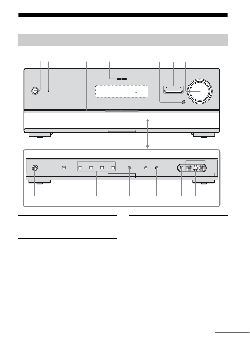
Description and location of parts
Front panel
12
?/1
PHONES
SPEAKERS
A.DIRECT
2 CH/
475
A.F.D. MOVIE MUSIC INPUT MODE DIMMER DISPLAY
Name Function
A ?/1 (on/standby) Press to turn the rece iver on
B Remote sensor Receives signals from
C White lamp Lights up when the receiver
D MULTI
CHANNEL
DECODING lamp
or off (page 35, 36, 53, 63).
remote commander.
is on.
Lights off when the
receiver is off or the
“DIMMER” is set to
“70% DOWN”.
Lights up when multi
channel audio signals are
decoded (page 120).
INPUT SELECTOR
AUTO CAL MIC
8
MUTING
VIDEO L AUDIO R
63
MULTI CHANNEL DECODING
Name Function
E Display The current st atus of the
F MUTING Press to turn off the sound
G INPUT
SELECTOR +/–
H MASTER
VOLUME
selected component or a list
of selectable items appears
here (page 9).
temporarily.
Press MUTING again to
restore the sound (page 47,
118).
Press repeatedly to select
the input source to
playback (page 47, 100,
104).
Turn to adjust the volume
level of all speakers at the
same time (page 47, 118).
MASTER VOLUME
VIDEO 2 IN
9q;qaqsqdqfqgqh
continued
GB
7

Name Function
I VIDEO 2 IN
jacks
J AUTO CAL MIC
jack
K DISPLAY Press repeatedly to select
L DIMMER Press repeatedly to adjust
M INPUT MODE Press to select the input
N 2CH/A.DIRECT Press to select a sound field
A.F.D.
MOVIE
MUSIC
O SPEAKERS Press to select the front
P PHONES jack Connects to headphones
Connects to a portable
audio/video component
such as a camcorder or
video game ( page 31, 47).
Connects to the supplied
optimizer microphone for
the Auto Calibration
function (page 40).
information displayed on
the display (page 81, 124).
the brightness of the display
(page 103).
mode when the same
components are connected
to both digital and analog
jacks (page 100).
(page 56, 57, 60).
speaker system (page 37).
(page 119).
GB
8
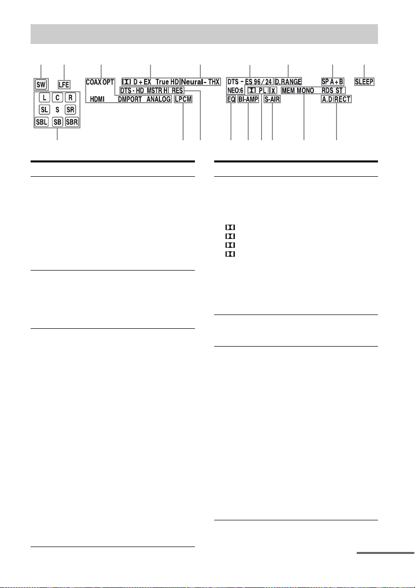
About the indicators on the display
12
qk
3
4 5
qj
Name Function
A SW Lights up when subwoofer is
B LFE Lights up when the disc being
C Input
indicators
COAX
OPT
HDMI
DMPORT
ANALOG
connected and the audio signal
is output from the
SUBWOOFER jack. While this
indicator lights up, the receiver
creates a subwoofer signal
based on the LFE signal in the
disc being played back or the
low frequency components of
the front channels.
played back contains an LFE
(Low Frequency Effect)
channel and the LFE channel
signal is actually being
reproduced.
Light up to indicate the current
input.
Lights up when INPUT MODE
is set to “AUTO” and the source
signal is a digital signal being
input through the COAXIAL
jack (page 100).
Lights up when INPUT MODE
is set to “AUTO” and the source
signal is a digital signal being
input through the OPTICAL
jack (page 100).
The receiver recognizes a
component connected via an
HDMI IN jack.
The DIGITAL MEDIA PORT
adapter is connected and
“DMPORT” is selected.
No digital signal is being input.
When INPUT MODE is set to
“ANALOG” or when the
“Analog Direct” is being
selected, it also lights up.
6
qh
qg
qf
qsqd
qa
Name Function
D Dolby
Digital
Surround
indicators
D
D EX
D+
Tru eHD
E Neural-THX Lights up when the receiver
F DTS(-ES)
indicators
DTS
DTS 96/24
NEO:6
DTS-ES
Lights up one of the respective
indicators when the receiver is
decoding the corresponding
Dolby Digital format signals.
Dolby Digital
Dolby Digital Surround EX
Dolby Digital Plus
Dolby TrueHD
Note
When playing a Dolby Digital
format disc, be sure that you
have made digital connections
and that INPUT MODE is set
to “AUTO” (page 100).
applies Neural-THX
processing to input signals.
Light up when DTS or DTSES signals are input.
Lights up when the receiver is
decoding DTS signals.
Lights up when the receiver is
decoding DTS 96 kHz/24 bit
signals.
Lights up when DTS Neo:6
Cinema/Music decoder is
activated (page 59).
Lights up when the receiver is
decoding DTS-ES signals.
Note
When playing a DTS format
disc, be sure that you have
made digital connections and
that INPUT MODE is set to
“AUTO” (page 100).
continued
87 9
q;
GB
9
Name Function
G D.RANGE Lights up when dynamic range
H SP A/SP B/
SP A+B
I SLEEP Lights up when the Sleep Timer is
J A.DIRECT Lights up when “Analog Direct”
K Tun in g
indicators
MEM
MONO
RDS
ST
L S-AIR Lights up when the S-AIR
M Dolby
Pro Logic
indicators
PL
PL II
PL IIx
N BI-AMP Lights up when “SB Assign” is set
O EQ Lights up when the equalizer is
compression is activated.
Lights up according to the front
speaker system used (page 37).
However, these indicators do not
light up if the speaker output is
turned off or if headphones are
connected.
activated.
is selected.
Lights up when the receiver tunes
in radio stations.
Lights up when a memory
function, such as Preset Memory
(page 53), etc., is activated.
Monaural broadcast
RDS information is received.
Note
“RDS” appears for models of area
code CEL, CEK only.
Stereo broadcast
transmitter (not supplied) is
connected.
Lights up one of the respective
indicators when the receiver
applies Dolby Pro Logic
processing to 2 channel signals in
order to output the center and
surround channel signals.
Dolby Pro Logic
Dolby Pro Logic II
Dolby Pro Logic IIx
Note
These indicators do not light up
when either the center speaker and
surround speaker is not connected.
to “BI-AMP” (page 105).
activated.
Name Function
P DTS-HD
indicators
DTS-HD
MSTR
DTS-HD HI
RES
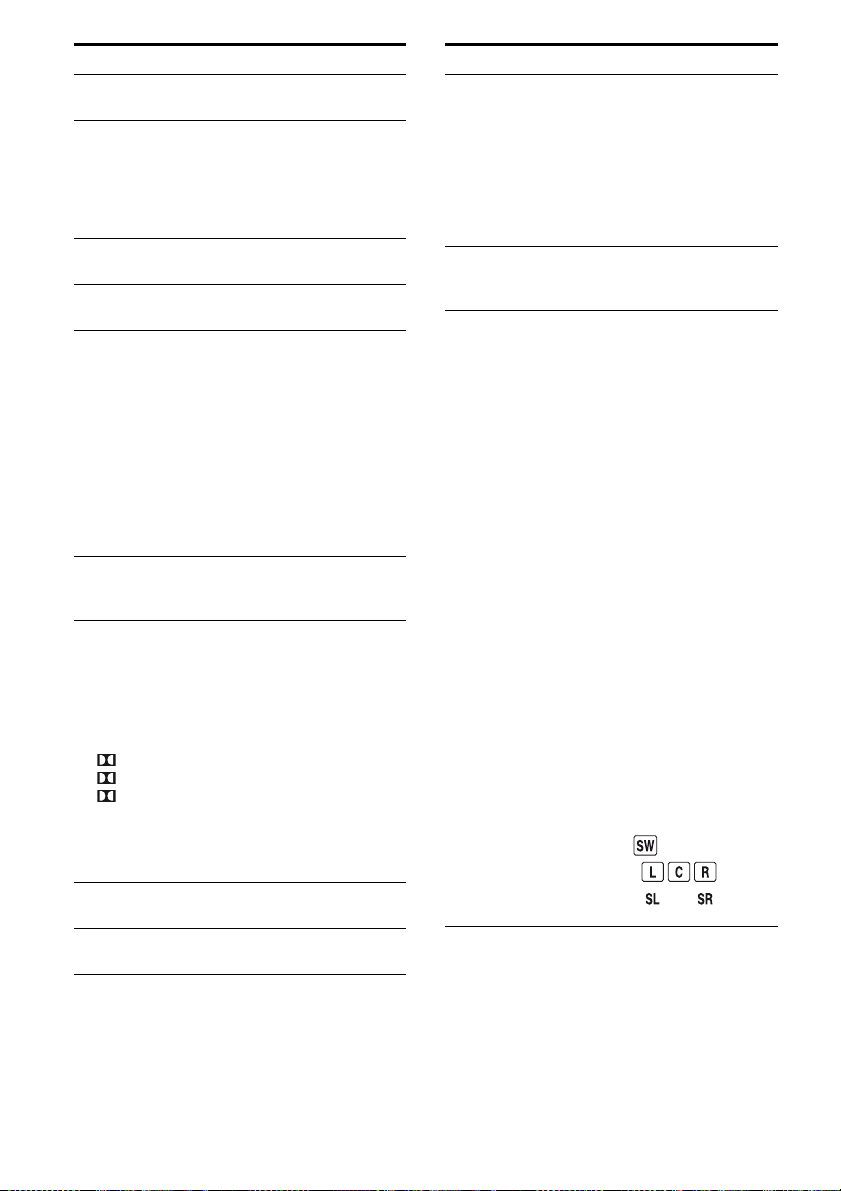
Q LPCM Lights up when Linear PCM
R Playback
channel
indicators
L
R
C
SL
SR
S
SBL
SBR
SB
Lights up one of the respective
indicators when the receiver is
decoding the corresponding
DTS-HD format signals.
DTS-HD Master Audio
DTS-HD High Resolution
Audio
(Pulse Code Modulation)
signals are input.
The letters (L, C, R, etc.)
indicate the channels being
played back. The boxes around
the letters vary to show how the
receiver downmixes the source
sound (based on the speaker
settings).
Front L eft
Front R ight
Center (monaural)
Surround Left
Surround Right
Surround (monaural or the
surround components obtained
by Pro Logic processing)
Surround Back Left
Surround Back Right
Surround Back (the surround
back components obtained by
6.1 channel decoding)
Example:
Recording format (Front/
Surround): 3/2.1
Output channel: When “SP
Pattern” is set to “3/0.1”
(page 66, 78)
Sound Field: “A.F.D. Auto”
10
GB
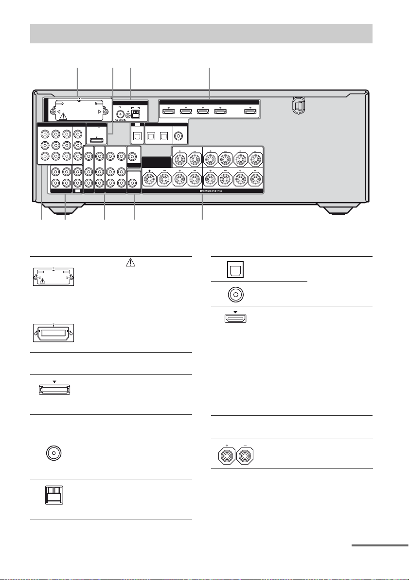
Rear panel
2
DMPORT
DC5V
OUT
0.7A MAX
VIDEO
VIDEO
VIDEO
IN
OUT
IN
AUDIO
AUDIO
AUDIO
IN
OUT
IN
SAT
BD
EZW-T100
COMPONENT VIDEO
IN 3
Y
P
B
/
C
B
P
R
/
C
R
ASSIGNABLE (INPUT ONLY)
L
R
SA-CD/CD/CD-R
143
IN 1
MONITOR
IN 2
OUT
IN
IN
TV
68
A S-AIR (EZW-T100)
With slot cover
slot
CAUTION
B DMPORT
DMPORT
jack
ANTENNA
AM
TV
OPTICAL IN
SAT IN BD IN
VIDEO
VIDEO
OUT
IN
SURROUND BACK/
MONITOR
AUDIO
OUT
SUBWOOFER
FRONT B/
BI-AMP
VIDEO 1
AUDIO
IN
L
R
Plea se do not remove
the slot cover until
you want to install
the wireless
transmitter.
Connects to a
wireless transmitter
(not supplied) (page
91).
Connects to a Sony
DIGITAL MEDIA
PORT adapter
(page 22).
IN 4
ASSIGNABLE (INPUT ONLY)
(ASSIGNABLE)
DIGITAL
OPTICAL
COAXIAL
DVD IN
IN 3
CENTER
SPEAKERS
HDMI
IN 2
LR
(for AUDIO)
IN 1
SURROUND
FRONT A
OUT
LR
LR
576
D DIGITAL INPUT/OUTPUT section
OPTICAL IN
jacks
COAXIAL IN
jack
HDMI IN/
OUT* jacks
Connects to a BD
player, etc. (page
20, 25, 28, 29, 30).
Connects to a DVD
player, satellite
tuner, or a Blu-ray
disc player. The
image is output to a
TV or a proj ector
while the sound can
be output from a TV
or/and speakers
connected to this
receiver (page 20,
25).
C ANTENNA section
FM
ANTENNA
jack
AM
ANTENNA
terminals
Connects to the FM
wire antenna (aerial)
supplied with this
receiver (page 34).
Connects to the AM
loop antenna (aerial)
supplied with this
receiver (page 34).
E SPEAKERS section
Connects to
speakers (page 18).
continued
11
GB
F AUDIO INPUT/OUTPUT section
White (L)
Red (R)
Black
AUDIO IN/
OUT jacks
AUDIO OUT
jack
Connects to a Super
Audio CD player,
etc. (page 20, 22,
25).
Connects to
subwoofer (page
18).
G VIDEO/AUDIO INPUT/OUTPUT
section
White (L)
Red (R)
Yellow
AUDIO IN/
OUT jacks
VIDEO IN/
OUT* jacks
Connects to a VCR,
Blu-ray disc player,
etc. (page 29, 30,
31).
H COMPONENT VIDEO INPUT/
OUTPUT section
Y, PB/CB,
Green
(Y)
P
R/CR IN/
OUT* jacks
Blue
(P
B/CB)
Red
(P
R/CR)
* You can watch the selected input image when you
connect the MONITOR OUT or HDMI OUT jack
to a TV (page 20). You can operate this receiver
using a GUI (Graphical User Interface) if you
connect HDMI OUT jack or COMPONENT
VIDEO MONITOR OUT jacks to a TV (page 36).
Connects to a BD
player, TV , satellite
tuner, etc. (page 20,
28, 29, 30).
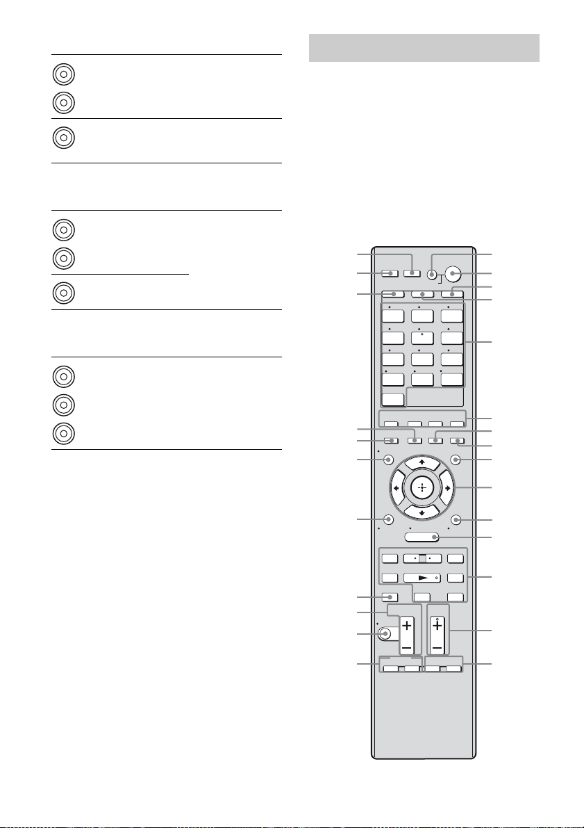
Remote commander
You can use the supplied remote to operate the
receiver and to control the Sony audio/video
components that the remote is assigned to
operate.
You can also program the remote to control
non-Sony audio/video components. For
details, see “Programming the remote” (page
109).
RM-AAP042
NIGHT
MODE
TOOLS/
OPTIONS
>
1
2
3
4
5
6
7
8
9
0
qa
qs
qd
qf
qg
wh
wg
wf
wd
ws
wa
w;
ql
qk
RM SET UP
THEATRE
SYSTEM STANDBY
SHIFT
TV AMP
1 2 3
VIDEO 1 VIDEO 2 BD
4 5 6
DVD
SAT TV
7 8 9
SA-CD/
CD
-/-- 0/10
CLEAR/>10
HDMI 4
2CH/
A.DIRECT
A.F.D. MOVIE MUSIC
INPUT
RESOLUTION
MODE
DISPLAY
O
HOME
RETURN/
EXIT
MENU
<
.
TUNING – TUNING +
mM
DISC SKIP D.TUNING
Xx
TV VOL
MASTER VOL
MUTING
qj
BD/DVD
TOP MENU MENU
qh
TV INPUT
WIDE
AV
?/1
SLEEP
TV CH
PRESET
F1 F2
DMPORTTUNER
ENT/MEM
<
?/1
HDMI 3HDMI 2HDMI 1
GUI MODE
12
GB

Name Function
A AV ?/1a)
(on/standby)
B ?/1
(on/standby)
Press to turn on or off the
audio/video components that
the remote is programmed to
operate.
To turn the TV on or off, press
TV (D) and then press AV
?/1.
If you press ?/1 (B) at the
same time, it will turn off the
receiver and other
components (SYSTEM
STANDBY).
Note
The function of the AV ?/1
switch changes automatically
each time you press the input
buttons (E).
Press to turn the receiver on or
set it to the standby mode.
To turn off all components,
press ?/1 and AV ?/1 (A) at
the same time (SYSTEM
STANDBY).
Saving the power in
standby mode.
When “Ctrl for HDMI” is set
to “OFF” (page 86) and
“S-AIR Stby” is set to “OFF”
(page 99).
C AMP Press to enable the receiver
D TV Press to light up the button. It
E Input buttons
(SAT
b)
)
operation (page 75).
changes the remote key
function to activate the
buttons with yellow printing.
It also activate the DISPLAY
(U), TOOLS/OPTIONS
(K), HOME (L), RETURN /
EXIT O (T), (J), and
V/v/B/b (J) buttons to
perform menu operations for
Sony TVs only.
Press one of the buttons to
select the component you
want to use. When you press
any of the input buttons, the
receiver turns on. The buttons
are factory assigned to control
Sony components (page 47).
You can program the remote
to control non-Sony
components following the
steps in “Programming the
remote” on page 109.
Name Function
Numeric
buttons
(number 5
ENT/MEM
CLEAR
a)
-/--
>10
F 2CH/
A.DIRECT
A.F.D.
MOVIE
MUSIC
a)
Press SHIFT (X), then press
a)
numeric buttons to
b)
)
– preset/tune to preset stations.
– select track numbers of the
CD player, DVD player, Bluray disc player or MD deck,
etc. Press 0/10 to select track
number 10.
– select channel numbers of
the VCR or satellite tuner,
etc.
Press TV (D) and then press
the numeric buttons to select
the TV channels.
a)
Press SHIFT (X), then press
ENT/MEM to
– enter the value after selecting
a channel, disc or track using
the numeric buttons.
– store a station during tuner
operation.
To enter the value of Sony TV,
press TV (D) and then press
ENT/MEM.
a)
Press SHIFT (X), then press
CLEAR to
– clear a mistake when you
press the incorrect numeric
button.
– return to continuous
playback, etc. of the satellite
tuner or DVD player.
Press SHIFT (X), then press
-/-- to select the channel entry
mode, either one or two digit
of the VCR or satellite tuner.
To select the channel entry
mode of the TV, press TV (D)
and then press -/--.
Press SHIFT (X), then press
>10 to
– select track numbers over 10
of the CD player, DVD
player, Blu-ray disc player or
MD deck, etc.
– select channel numbers of
the Digital CATV terminal.
Press to select a sound field
(page 56, 57, 60).
continued
13
GB
Name Function
a)
G SLEEP Press to activate the Sleep
H NIGHT MODE Press to activate the NIGHT
I GUI MODE P ress to displa y the GUI menu
J
,
V/v/B/b
K TOOLS/
OPTIONS
MENU
a)
a)
L HOME
M ./>
m/M
a)b)
N
a)
X
a)
x
a)
<
<
/
TUNING +/–
D.TUNING
N TV CH +
PRESET
b)/–a)
+
Timer function and the
duration which the receiver
turns off automatically
(page 103).
MODE function (page 104).
on the TV screen.
Press V/v/B/b to select the
menu items.
a)
Then press to enter the
selection.
Press to display and select
a)
items from the option menus
for receiver, DVD player,
Blu-ray disc player or satellite
tuner.
Press TV (D) and then press
TOOLS/OPTIONS to display
the options of Sony TV.
,
Press to display the menu to
operate the audio/video
components.
To display the menus of Sony
TV, press TV (D) and then
press HOME.
a)
Press to operate the DVD
a)
player, Blu-ray disc player,
CD player, MD deck, tape
deck, or component
connected to the DIGITAL
MEDIA PORT adapter, etc.
Press to replay the previous
scene or fast forward the
current scene of the DVD
player or Blu-ray disc player,
etc.
a)
Press to scan a station.
a)
Press to enter direct tuning
mode (page 52, 84).
b)/–a)
Press TV (D) and then press
TV CH +/– to select preset
TV channels.
Press to
– select preset stations.
– select preset channels of the
VCR, satellite tuner,
Blu-ray disc player, DVD
player, LD player, DVD/
VHS COMBO, or DVD/
HDD COMBO.
Name Function
a)
MENU
BD/DVD
a)
MENU
TV INPUT
a)
WIDE
MASTER
VOL +/–
a)
Press BD or DVD (E), then
press F1 or F2 to select a
component.
• DVD/HDD COMBO
F1: HDD
F2: DVD disc, Blu-ray disc
• DVD/VHS COMBO
F1: DVD disc, Blu-ray disc
F2: VHS
Press to display the menu or
on-screen guide of the DVD
player, Blu-ray disc player,
PSX or DVD/VHS COMBO
on the TV screen. Then, use
V/v/B/b (J) and (J) to
perform menu operations.
Press to display the menu of
the DVD player or Blu-ray
disc player on the TV screen.
Then, use V /v/B/b (J) and
(J) to perform menu
operations.
a)
Press TV (D) and then press
TV INPUT to select the input
signal (TV input or video
input).
Press TV (D) and then press
WIDE to select the wide
picture mode.
a)
Press to turn off the sound
temporarily. Press the button
again to restore the sound.
To mute the sound of the TV,
press TV (D) and then press
MUTING.
a)
Press TV (D) and then press
TV VOL +/– to adjust the TV
volume level.
Press to adjust the volume
a)
level of all speakers at the
same time.
a)
Press to skip disc when using
a multi-disc changer.
O F1a), F2
P BD/DVD TOP
Q MUTING
R TV VOL +/–
S DISC SKIP
GB
14

Name Function
T RETURN/
EXIT O
U DISPLAY
V RESOLUTION Press repeatedly to change the
W INPUT MODE Press to select the input mode
X SHIFT Press to light up the button. It
Y THEATRE Press to turn the Theatre mode
Z RM SET UP Press to set up the remote.
a)
See the table on page 108 for information on the
buttons that you can use to control each
component.
b)
The number 5/SAT, TV CH +/PRESET + and N
buttons have tactile dots. Use the tactile dots as
references when operating the receiver.
Press to
a)
– return to the previous menu.
– exit the menu while the
menu or on-screen guide of
the VCD player, DVD
player, etc. is displayed on
the TV screen.
To return to the previous
menu of Sony TV, press TV
(D) and then press
RETURN/EXIT O.
a)
Press to display the current
status of or information on
components connected to the
receiver.
Note
In the GUI MODE, press the
button to display the menu on
the TV screen.
resolution of signals output
from the HDMI OUT or
COMPONENT VIDEO
MONITOR OUT jack (page
72).
when the same components
are connected to both digital
and analog jacks (page 100).
changes the remote button
function to activate the
buttons with pink printing.
on and off when connecting
the receiver to products
featuring “BRAVIA” Sync.
Notes
• Some functions explained in this section may not
work depending on the model.
• The above explanation is intended to serve as an
example only. Therefore, depending on the
component, the above operation may not be
possible or may operate differently than described.
15
GB
Getting Started
1: Installing speakers
This receiver allows you to use a 7.1 channel
system (7 speakers and one subwoofer).
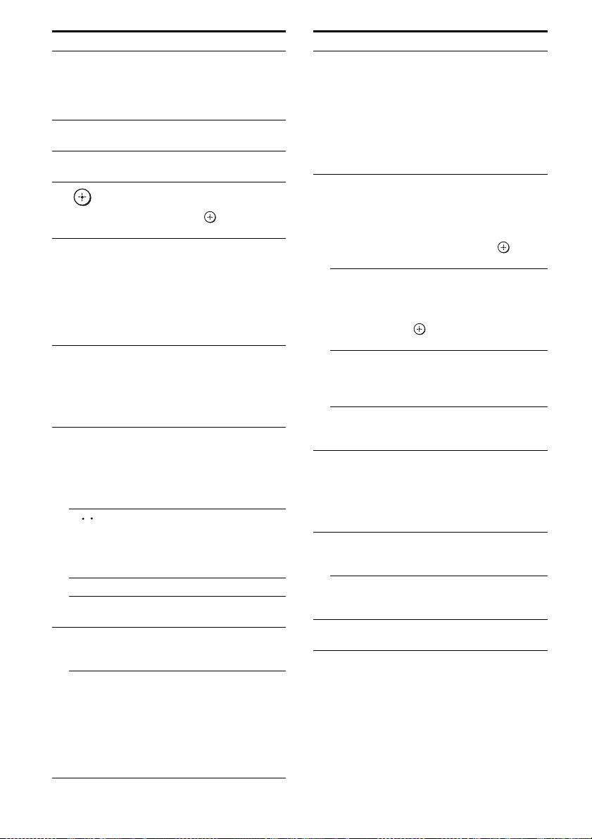
Enjoying a 5.1/7.1 channel
system
To fully enjoy theater-like multi channel
surround sound requires five speakers (two
front speakers, a center speaker, and two
surround speakers) and a subwoofer (5.1
channel).
Example of a 5.1 channel
speaker system configuration
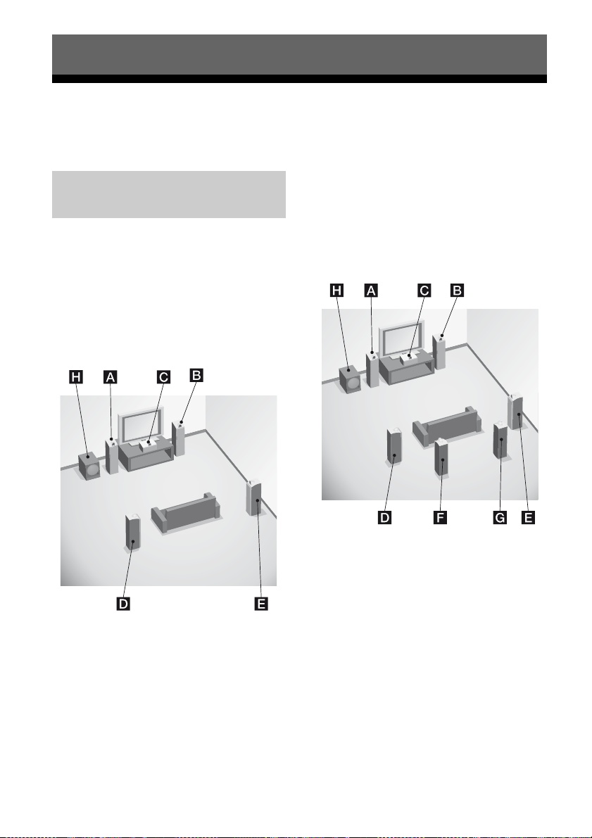
You can enjoy high fidelity reproduction of
DVD or Blu-ray disc software recorded sound
in the Surround EX format if you connect one
additional surround back speaker (6.1 channel
system) or two surround back speakers (7.1
channel system).
Example of a 7.1 channel
speaker system configuration
AFront speaker (left)
BFront speaker (right)
CCenter speaker
DSurround speaker (left)
ESurround speaker (right)
HSubwoofer
GB
16
AFront speaker (left)
BFront speaker (right)
CCenter speaker
DSurround speaker (left)
ESurround speaker (right)
FSurround back speaker (left)
GSurround back speaker (right)
HSubwoofer
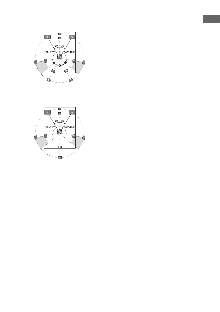
Tips
• When you connect a 7.1 channel speaker system,
the angle A should be the same.
• When you connect a 6.1 channel speaker system,
place the surround back speaker behind the
listening position.
Getting Started
• Since the subwoofer does not emit highly
directional signals, you can place it wherever you
want.
17
GB
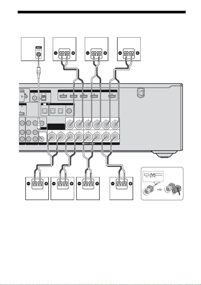
2: Connecting speakers
Before connecting cords, be sure to disconnect the AC power cord (mains lead).
H
CD
E
AB
(for AUDIO)
CENTER
SPEAKERS
HDMI
IN 1
R
SURROUND
FRONT A
OUT
L
LRLR
PORT
5V
A MAX
VIDEO
AUDIO
ANTENNA
AM
TV
DIGITAL
OPTICAL
OPTICAL IN
SAT IN BD IN
VIDEO
VIDEO
VIDEO
OUT
OUT
IN
IN
SURROUND BACK/
MONITOR
AUDIO
OUT
SUBWOOFER
FRONT B/
BI-AMP
AUDIO
AUDIO
OUT
IN
IN
L
R
VIDEO 1
BD
IN 3
IN 4 IN 2
ASSIGNABLE (INPUT ONLY)
(ASSIGNABLE)
COAXIAL
DVD IN
B
10 mm
FG
B
A Monaural audio cord (not supplied)
B Speaker cord (not supplied)
AFront speaker A (left)
BFront speaker A (right)
CCenter speaker
DSurround speaker (left)
GB
18
A
ESurround speaker (right)
FSurround back speaker (left)
GSurround back speaker (right)
HSubwoofer
d)
a)b)c)
a)b)c)

a)
If you connect only one surround back speaker,
connect it to the SPEAKERS SURROUND
BACK/FRONT B/BI-AMP L terminals.
b)
If you are not using surround back speaker, and
you have an additional front speaker system,
connect the additional front speaker system to the
SPEAKERS SURROUND BACK/FRONT B/
BI-AMP terminals. Set “SB Assign” to “Speaker
B” in the Speaker Settings menu (page 66).
You can select the front speaker system you want
to use with SPEAKERS on the front panel
(page 37).
c)
If you are not using surround back speakers, you
can connect the front speakers to the SPEAKERS
SURROUND BACK/FRONT B/BI-AMP
terminals using a bi-amplifier connection
(page 105).
Set “SB Assign” to “BI-AMP” in the Speaker
Settings menu (page 66).
d)
When you connect a subwoofer with an auto
standby function, turn off the function when
watching movies. If the auto standby function is
set to on, it turns to standby mode automatically
based on the level of the input signal to a
subwoofer, then sound may not be output.
Note
Before connecting the AC power cord (mains lead),
make sure that metallic wires of the speaker cords
are not touching each other between the
SPEAKERS terminals.
Getting Started
19
GB
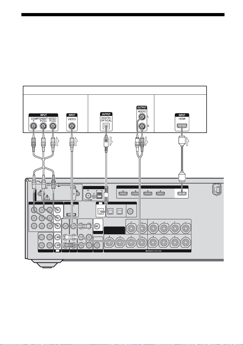
3: Connecting the TV
You can watch the selected input image when
you connect the HDMI OUT or MONITOR
OUT jack to a TV. You can operate this
receiver using a GUI (Graphical User
Interface) if you connect HDMI OUT jack or
COMPONENT VIDEO MONITOR OUT
jacks to a TV.
TV
Video signals
AB
ANTENNA
EZW-T100
COMPONENT VIDEO
IN 3
Y
P
B/
C
B
P
R/
C
R
ASSIGNABLE (INPUT ONLY)
L
R
SA-CD/CD/CD-R
IN 1
IN 2
OUT
IN
MONITOR
IN
TV
DMPORT
DC5V
OUT
0.7A MAX
VIDEO
VIDEO
VIDEO
VIDEO
IN
OUT
IN
IN
AUDIO
AUDIO
AUDIO
AUDIO
IN
OUT
IN
IN
L
R
VIDEO 1
SAT
BD
Audio signals Audio/video signals
CD
AM
TV
DIGITAL
OPTICAL IN
SAT IN BD IN
VIDEO
OUT
SURROUND BACK/
FRONT B/
MONITOR
BI-AMP
AUDIO
OUT
SUBWOOFER
It is not necessary to connect all the cables.
Connect audio and video cords according to
the jacks of your components.
Before connecting cords, be sure to disconnect
the AC power cord (mains lead).
E
IN 4
ASSIGNABLE (INPUT ONLY)
(ASSIGNABLE)
OPTICAL
IN 3
COAXIAL
DVD IN
(for AUDIO)
CENTER
LR
SPEAKERS
HDMI
IN 2
IN 1
SURROUND
FRONT A
OUT
LR
LR
A Component video cord (not supplied)
B Video cord (not supplied)
C Optical digital cord (not supplied)
D Audio cord (not supplied)
E HDMI cable (not supplied)
Sony recommends that you use an HDMI-authorized cable or Sony HDMI cable.
GB
20

Notes
• Be sure to turn on the receiver when the video and
audio of a playback component are being output to
a TV via the receiver. If the power supply of the
receiver is not turned on, neither video nor audio is
transmitted.
• Connect image display components such as a TV
monitor or a projector to the HDMI OUT or
MONITOR OUT jack on the receiver. You may
not be able to record, even if you connect recording
components.
• Depending on the status of the connection between
the TV and the antenna (aerial), the image on the
TV screen may be distorted. In this case, place the
antenna (aerial) farther away from the receiver.
• When connecting optical digital cords, insert the
plugs straight in until they click into place.
• Do not bend or tie optical digital cords.
Tips
• The receiver has a video conversion function. For
details, see “Function for conversion of video
signals” (page 32).
• The sound of the TV is output from the speakers
connected to the receiver if you connect the audio
output jack of the TV to the TV IN jacks of the
receiver. In this configuration, set the sound output
jack of t he TV to “Fixed” if it can be switched
between either “Fixed” or “Variable”.
Getting Started
21
GB
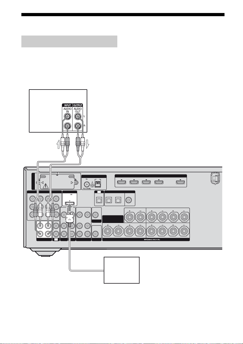
4a: Connecting the audio components
After connecting your audio component,
Connecting audio components
The following illustration shows how to
connect a Super Audio CD player, CD player,
CD recorder and DIGITAL MEDIA PORT
adapter. Before connecting cords, be sure to
disconnect the AC power cord (mains lead).
Super Audio CD player,
CD player, CD recorder
A
proceed to “4b: Connecting the video
components” (page 24) or “5: Connecting the
antennas (aerials)” (page 34).
EZW-T100
COMPONENT VIDEO
IN 3
Y
P
B/
C
B
P
R/
C
R
ASSIGNABLE (INPUT ONLY)
L
R
SA-CD/CD/CD-R
IN 1
IN 2
OUT
IN
MONITOR
IN
TV
DMPORT
DC5V
OUT
0.7A MAX
VIDEO
VIDEO
VIDEO
IN
OUT
IN
AUDIO
AUDIO
AUDIO
IN
OUT
IN
VIDEO 1
SAT
BD
A Audio cord (not supplied)
GB
22
VIDEO
AUDIO
L
R
ANTENNA
IN
IN
SUBWOOFER
VIDEO
OUT
MONITOR
AUDIO
OUT
AM
TV
OPTICAL IN
SURROUND BACK/
IN 3
IN 4
ASSIGNABLE (INPUT ONLY)
(ASSIGNABLE)
DIGITAL
OPTICAL
COAXIAL
SAT IN BD IN
FRONT B/
BI-AMP
DIGITAL MEDIA
PORT adapter
DVD IN
(for AUDIO)
CENTER
LR
SPEAKERS
HDMI
IN 2
IN 1
SURROUND
FRONT A
OUT
LR
LR
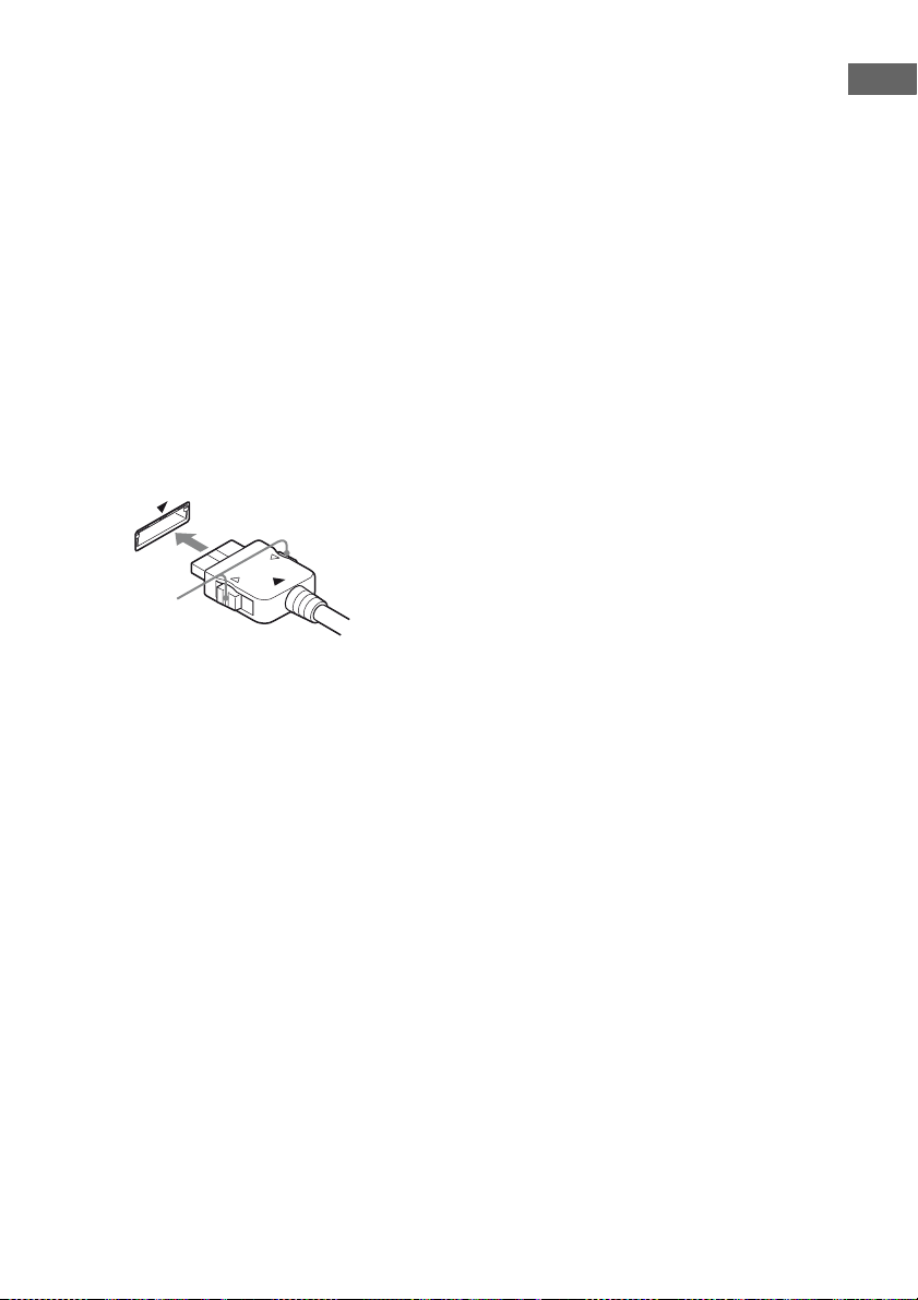
Notes on connecting DIGITAL
MEDIA PORT adapter
• Do not connect or disconnect the DIGITAL
MEDIA PORT adapter while the receiver is
turned on.
• Be sure to make DMPORT connections
firmly, insert the connector straight in.
• As the connector of the DIGITAL MEDIA
PORT adapter is fragile, be sure to handle
with care when placing or moving the
receiver.
• When connecting the DIGITAL MEDIA
PORT adapter, be sure the connector is
inserted with the arrow mark facing towards
the arrow mark on the DMPORT jack. To
detach the DIGITAL MEDIA PORT
adapter, press and hold A and then pull out
the connector.
A
Getting Started
23
GB
4b: Connecting the video components
How to connect your
components
This section describes how to connect your
video components to this receiver. Before you
begin, see “Component to be connected”
below for the pages which describe how to
connect each component. Before connecting
cords, be sure to disconnect the AC power
cord (mains lead).
After connecting all your components,
proceed to “5: Connecting the antennas
(aerials)” (page 34).
Component to be connected
Component Page
TV 20
With HDMI jack 25
DVD player 28
Blu-ray disc player 29
Satellite tuner, Set-top box 30
DVD recorder, VCR 31
Camcorder, video game, etc. 31
If you want to connect several
digital components, but cannot
find an unused input
See “Enjoying the sound/images from other
inputs” (page 100).
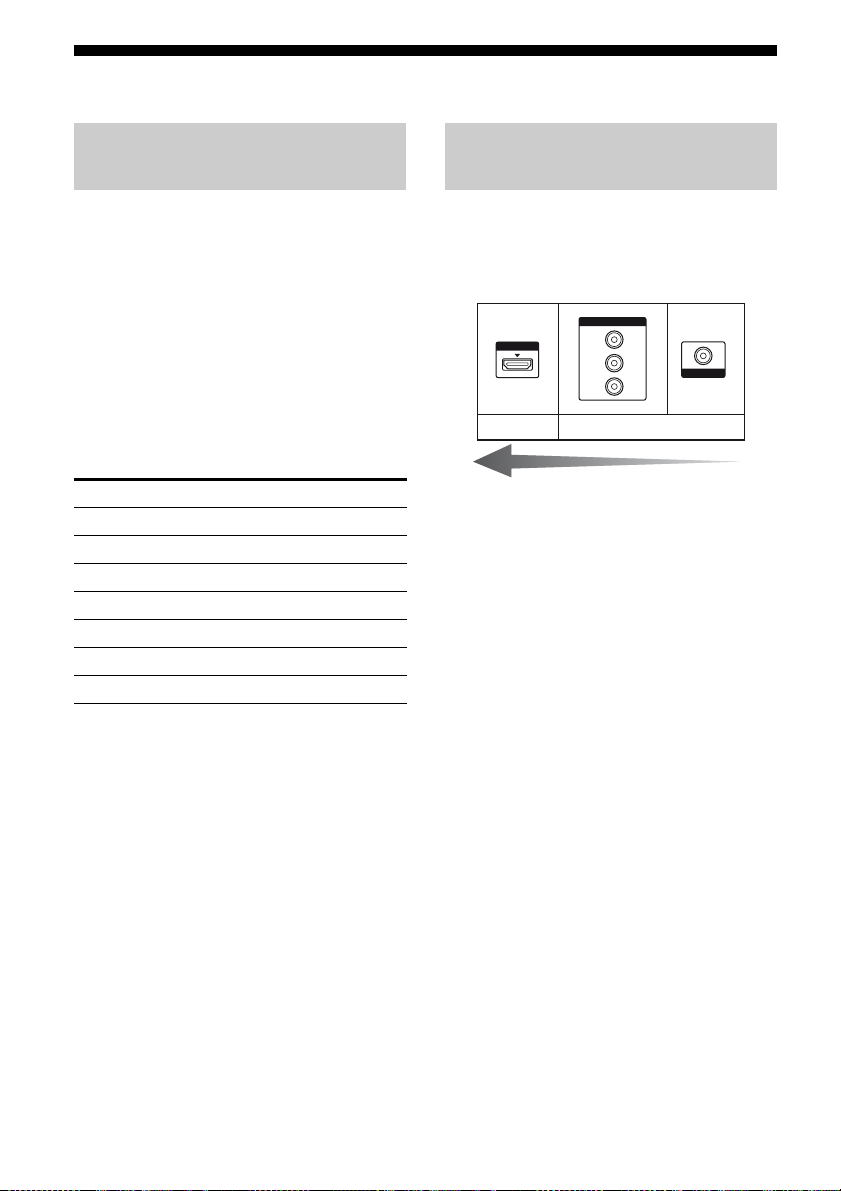
Video input/output jacks to be
connected
The image quality depends on the connecting
jack. See the illustration that follows.
Select the connection according to the jacks on
your components.
COMPONENT VIDEO
HDMI
Digital Analog
Note
Be sure to turn on the receiver when the video and
audio of a playback component are being output to a
TV via the recei ver. If the power supp ly of the
receiver is not turned on, neither video nor audio is
transmitted.
Converting video signals
This receiver is equipped with a function for
up-converting video signals. For details, see
“Function for conversion of video signals”
(page 32).
Y
P
B
/
C
B
P
R
/
C
R
High quality image
VIDEO
24
GB

Connecting components with
HDMI jacks
HDMI is the abbreviated name for HighDefinition Multimedia Interface. It is an
interface which transmits video and audio
signals in digital format.
Sony recommends that you connect
components to the receiver using an HDMI
cable.
With HDMI, you can easily enjoy both high
quality sound and high quality images.
However, it is necessary to connect
the audio output of the TV to the
audio input of the receiver using an
optical digital cord to listen to the
TV multi channel surround sound
broadcasting from the receiver.
By connecting Sony “BRAVIA” Sync
compatible components using HDMI cables,
““BRAVIA” Sync Features” makes
operations simpler (page 85).
Notes
• Be sure to change the factory setting of the HDMI
1–4 input button on the remote so that you can use
the button to control your components. For details,
see “Programming the remote” (page 109).
• You can also rename the HDMI input so that it can
be displayed on the receiver’s display. For details,
see “Naming the input (Name Input)” (page 48).
HDMI features
• A digital audio signals transmitted by HDMI
can be output from the speakers connected to
the receiver. This signal supports Dolby
Digital, DTS, and Linear PCM.
• The receiver can receive Multi Linear PCM
(up to 8 channels) with a sampling frequency
of 192 kHz or less with an HDMI
connection.
• Analog video signals input to the VIDEO
jack or COMPONENT VIDEO jacks can be
up-converted as HDMI signals. Audio
signals are not output from an HDMI OUT
jack when the image is converted.
• This receiver supports High Bitrate Audio
(DTS-HD Master Audio, Dolby TrueHD),
Deep Colour and x.v.Colour transmission,
extended by HDMI version 1.3.
• This receiver supports the Control for HDMI
function. For details, see ““BRAVIA” Sync
Features” (page 85).
• HDMI 3 input has a better sound quality.
When you need a higher sound quality,
connect your component to the HDMI IN 3
(for AUDIO) jack and select HDMI 3 as
input.
Getting Started
continued
25
GB
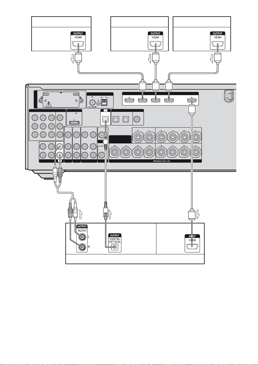
Satellite tuner, Set-top box
DVD player
Blu-ray disc player
Audio/video
signals
EZW-T100
COMPONENT VIDEO
IN 3
IN 2
Y
B/
P
C
B
P
R/
C
R
ASSIGNABLE (INPUT ONLY)
OUT
L
R
SA-CD/CD/CD-R
IN 1
Audio/video
signals
SURROUND
FRONT A
A
OUT
LR
LR
Audio/video
signals
A
ANTENNA
AM
TV
VIDEO
OUT
MONITOR
AUDIO
OUT
OPTICAL IN
DIGITAL
OPTICAL
SAT IN BD IN
SURROUND BACK/
FRONT B/
BI-AMP
IN 1
DMPORT
MONITOR
DC5V
OUT
0.7A MAX
VIDEO
VIDEO
VIDEO
VIDEO
IN
OUT
IN
IN
AUDIO
AUDIO
AUDIO
AUDIO
IN
OUT
IN
IN
IN
IN
SAT
TV
L
R
SUBWOOFER
VIDEO 1
BD
A
IN 3
IN 4
ASSIGNABLE (INPUT ONLY)
(ASSIGNABLE)
COAXIAL
DVD IN
CENTER
SPEAKERS
(for AUDIO)
LR
HDMI
IN 2
B
C
Audio signals
Audio/video
signals
TV, projector, etc.
A HDMI cable (not supplied)
Sony recommends that you use an HDMI-authorized cable or Sony HDMI cable.
BAudio cord (not supplied)
COptical digital cord (not supplied)
a)
Connect at least one of the audio cords (B or C).
GB
26
a)
a)
A

Notes on connecting cables
• We recommend that you use an HDMI cable
with the HDMI logo (made by Sony) for the
HDMI jack corresponding to high speed (an
HDMI version 1.3a, category 2 cable) when
you view images or listen to sound during a
Deep Colour transmission or when you
watch a video image of 1080p or higher.
• We do not recommend using an HDMI-DVI
conversion cable. When you connect an
HDMI-DVI conversion cable to a DVI-D
component, the sound and/or the image may
not be output. Connect other audio cords or
digital connecting cords, then set “Input
Assign” in the Input Option menu when the
sound is not output correctly.
Notes on HDMI connections
• An audio signal input to the HDMI IN jack
is output from the SPEAKERS jacks and
HDMI OUT jack. It is not output from any
other audio jacks.
• A video signal input to the HDMI IN jack
can only be output from the HDMI OUT
jack. The video input signals cannot be
output from the VIDEO OUT jacks or
MONITOR OUT jacks.
• The audio and video signals of HDMI input
are not output from the HDMI OUT jack
while the receiver menu is displayed.
• When you want to listen to the sound from
the TV speaker, set “Audio Out” to
“TV+AMP” in the HDMI Settings menu
(page 74). If you cannot play back multi
channel audio source, set to “AMP”.
However, the sound will not output from the
TV speaker.
• DSD signals of Super Audio CD are not
input and output.
• Be sure to turn on the receiver when the
video and audio of a playback component
are being output to a TV via the receiver. If
the power supply of the receiver is not
turned on, neither video nor audio is
transmitted.
• Audio signals (sampling frequency, bit
length, etc.) transmitted from an HDMI jack
may be suppressed by the connected
component. Check the setup of the
connected component if the image is poor or
the sound does not come out of a component
connected via the HDMI cable.
• Sound may be interrupted when the
sampling frequency, the number of channels
or audio format of audio output signals from
the playback component is switched.
• When the connected component is not
compatible with copyright protection
technology (HDCP), the image and/or the
sound from the HDMI OUT jack may be
distorted or may not be output.
In this case, check the specification of the
connected component.
• You can enjoy High Bitrate Audio (DTS-HD
Master Audio, Dolby TrueHD), multi
channel Linear PCM only with an HDMI
connection.
• Set the image resolution of the playback
component to more than 720p to enjoy High
Bitrate Audio (DTS-HD Master Audio,
Dolby TrueHD).
• The image resolution of playback
component may need certain settings be
made before you can enjoy multi channel
Linear PCM. Refer to the operating
instructions of the playback component.
• Not every HDMI component supports all
functions that are defined by the specified
HDMI version. For example, components
that support HDMI, version 1.3a, may not
support Deep Colour.
• Refer to the operating instructions of each
connected component for details.
Getting Started
27
GB
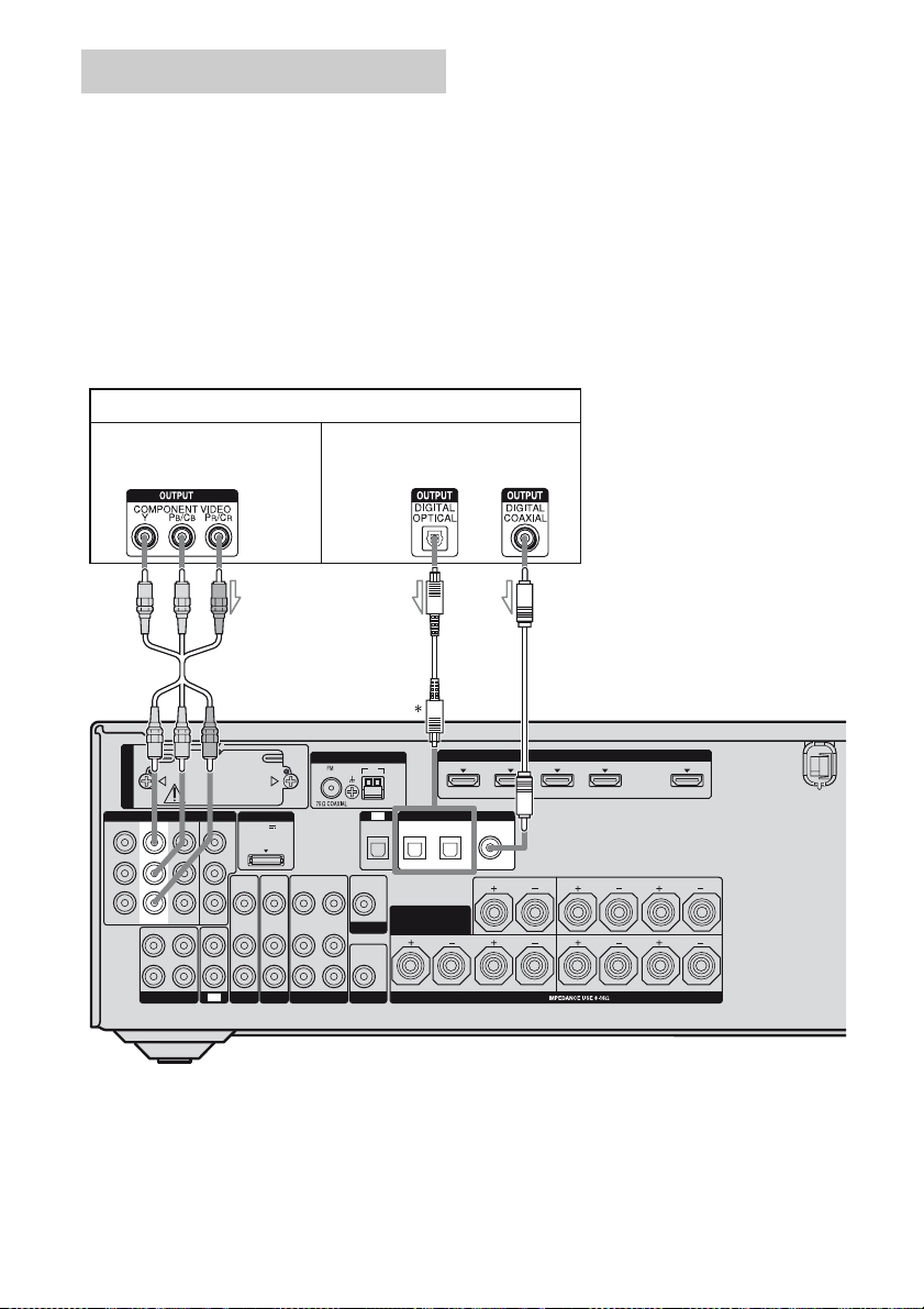
Connecting a DVD player
The following illustration shows how to
connect a DVD player.
It is not necessary to connect all the cords.
Connect audio and video cords according to
the jacks of your components.
Notes
• The COMPONENT VIDEO IN 2 jacks have been
assigned to the DVD player. If you connect your
DVD player to the COMPONENT VIDEO IN 1 or
IN 3 jacks, set “Input Assign” in the Input Option
menu (page 100).
DVD player
Video signals Audio signals
• To input multi channel digital audio from the DVD
player, set the digital audio output setting on the
DVD player. Refer to the operating instructions
supplied with the DVD player.
• When connecting optical digital cords, insert the
plugs straight in until they click into place.
• Do not bend or tie optical digital cords.
Tip
All the digital audio jacks are compatible wit h
32 kHz, 44.1 kHz, 48 kHz, and 96 kHz sampling
frequencies.
A
ANTENNA
AM
EZW-T100
TV
VIDEO
OUT
MONITOR
AUDIO
OUT
OPTICAL IN
DIGITAL
OPTICAL
SAT IN BD IN
SURROUND BACK/
FRONT B/
BI-AMP
COMPONENT VIDEO
IN 3
IN 2
Y
B/
P
C
B
P
R/
C
R
ASSIGNABLE (INPUT ONLY)
OUT
L
R
SA-CD/CD/CD-R
IN 1
DMPORT
MONITOR
DC5V
OUT
0.7A MAX
VIDEO
VIDEO
VIDEO
VIDEO
IN
OUT
IN
IN
AUDIO
AUDIO
AUDIO
AUDIO
IN
OUT
IN
IN
IN
IN
TV
SAT
L
R
SUBWOOFER
VIDEO 1
BD
A Component video cord (not supplied)
B Optical digital cord (not supplied)
C Coaxial digital cord (not supplied)
* When you connect a component equipped with an
OPTICAL jack, set “Input Assign” in the Input
Option menu.
B
IN 3
IN 4
ASSIGNABLE (INPUT ONLY)
(ASSIGNABLE)
COAXIAL
DVD IN
CENTER
SPEAKERS
(for AUDIO)
LR
IN 2
C
HDMI
IN 1
SURROUND
FRONT A
OUT
LR
LR
28
GB
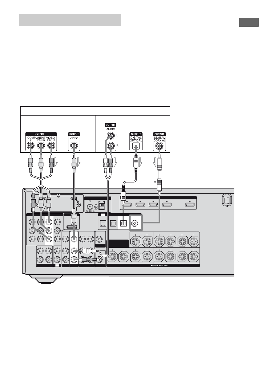
Connecting a Blu-ray disc player
The following illustration shows how to
connect a Blu-ray disc player.
It is not necessary to connect all the cords.
Connect audio and video cords according to
the jacks of your components.
Notes
• The COMPONENT VIDEO IN 1 jacks have been
assigned to the Blu-ray disc player. If you connect
your Blu-ray disc player to the COMPONENT
VIDEO IN 2 or IN 3 jacks, set “Input Assign” in
the Input Option menu (page 100).
Blu-ray disc player
Video signals Audio signals
• To input multi channel digital audio from the Bluray disc player, set the digital audio output setting
on the Blu-ray disc player. Refer to the operating
instructions supplied with the Blu-ray disc player.
• When connecting optical digital cords, insert the
plugs straight in until they click into place.
• Do not bend or tie optical digital cords.
Tip
All the digital audio jacks are compatible with
32 kHz, 44.1 kHz, 48 kHz, and 96 kHz sampling
frequencies.
Getting Started
A
ANTENNA
AM
EZW-T100
TV
VIDEO
OUT
MONITOR
AUDIO
OUT
OPTICAL IN
DIGITAL
OPTICAL
SAT IN BD IN
SURROUND BACK/
FRONT B/
BI-AMP
COMPONENT VIDEO
IN 3
Y
B/
P
C
B
P
R/
C
R
ASSIGNABLE (INPUT ONLY)
L
R
SA-CD/CD/CD-R
MONITOR
IN
TV
DMPORT
DC5V
OUT
0.7A MAX
VIDEO
VIDEO
VIDEO
VIDEO
IN
OUT
IN
IN
AUDIO
AUDIO
AUDIO
AUDIO
IN
OUT
IN
IN
L
R
SUBWOOFER
VIDEO 1
SAT
BD
IN 1
IN 2
OUT
IN
A Component video cord (not supplied)
B Video cord (not supplied)
C Audio cord (not supplied)
D Optical digital cord (not supplied)
E Coaxial digital cord (not supplied)
* When you connect a component equipped with an
COAXIAL jack, set “Input Assign” in the Input
Option menu.
CB
IN 3
IN 4 IN 2
ASSIGNABLE (INPUT ONLY)
(ASSIGNABLE)
COAXIAL
DVD IN
CENTER
SPEAKERS
DE
HDMI
(for AUDIO)
LR
IN 1
SURROUND
FRONT A
OUT
LR
LR
29
GB
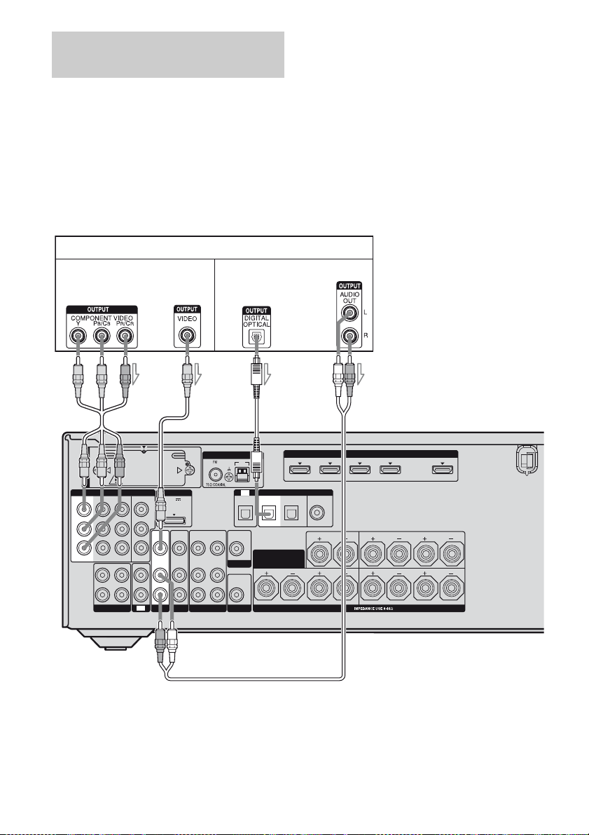
Connecting a satellite tuner,
set-top box
The following illustration shows how to
connect a satellite tuner or set-top box.
It is not necessary to connect all the cords.
Connect audio and video cords according to
the jacks of your components.
Satellite tuner, Set-top box
Video signals Audio signals
Notes
• The COMPONENT VIDEO IN 3 jacks have been
assigned to the satellite tuner. If you connect your
satellite tuner to the COMPONENT VIDEO IN 1
or IN 2 jacks, set “Input Assign” in the Input
Option menu (page 100).
• When connecting optical digital cords, insert the
plugs straight in until they click into place.
• Do not bend or tie optical digital cords.
Tip
All the digital audio jacks are compatible wit h
32 kHz, 44.1 kHz, 48 kHz, and 96 kHz sampling
frequencies.
EZW-T100
COMPONENT VIDEO
IN 3
IN 2
Y
P
B/
C
B
P
R/
C
R
ASSIGNABLE (INPUT ONLY)
OUT
L
R
SA-CD/CD/CD-R
BA
ANTENNA
MONITOR
IN
TV
DMPORT
DC5V
OUT
0.7A MAX
VIDEO
VIDEO
VIDEO
VIDEO
OUT
IN
IN
IN
AUDIO
AUDIO
AUDIO
AUDIO
OUT
IN
IN
IN
SAT
L
R
SUBWOOFER
VIDEO 1
BD
IN 1
IN
OPTICAL IN
VIDEO
OUT
MONITOR
AUDIO
OUT
AM
TV
C
DIGITAL
SAT IN BD IN
SURROUND BACK/
FRONT B/
BI-AMP
A Component video cord (not supplied)
B Video cord (not supplied)
C Optical digital cord (not supplied)
D Audio cord (not supplied)
IN 4
ASSIGNABLE (INPUT ONLY)
(ASSIGNABLE)
OPTICAL
COAXIAL
DVD IN
IN 3
CENTER
SPEAKERS
(for AUDIO)
LR
D
HDMI
IN 2
IN 1
SURROUND
FRONT A
OUT
LR
LR
30
GB
 Loading...