

Sony STR-DG810 Owner’s Manual
SONY_ 28o8o39,,1tt
Multi Channel AV
Receiver
Operating Instructions
Owner's Record
The model and serial numbers are located on the rear of the unit. Record the
serial number in the space provided below. Refer to them whenever you call
upon your Sony dealer regarding this product.
Model No. Serial No.
STR-DG810
@2007Sony Corporation

To reduce the risk of fire or electric
shock, do not expose this apparatus to
rain or moisture.
To preveut fire, do not cover the vmltilation of the
:Jpp:u'atus with newspapers, table-cloths, curtains,
etc. And don't place lighted candles on the
apparatus.
To prevent fire or shock hazard, do not place objects
filled with liquids, such as vases, on the apparatus.
Do i1111install the appliance in a confined space,
suc 1 as a bookcase or bu 1- I/ cab nel.
Install this system so that the power cord can be
unplugged from the wall socket immediately in the
evem of trouble.
general house wasle: dispose of
<_(_) Don't throw away batteries with
them correclly as chemical waste.
For customers in the United
States
WARNING
This equipment has been tested and l\mnd to comply
with the limits for a Class B digital device, pursuant
to Part 15 of the FCC Rules. These limits are
designed to provide reasonable protection against
harmful interference in a residential installation.
This equipment generates, uses. and c:m radiate
radio l'requency energy :rod. if not installed and used
in accord:race with the instructions, may cause
harmful interference to radio communications.
However. there is i1o guarantee that imefference will
not occur in a particular inst:dlation. If this
equipment does cause harmful interfcrm]ce to radio
or television reception, which can be determined by
turning the equipment off :rod on. the user is
encouraged to try to correct the interference by one
or more of the following measures:
Reorient or relocate the receiving antenna.
Increase tim separation between the equipment
:md receiver.
Connect the equipment into :m outlet on a circuit
diffcrmlt from that to which the receiver is
counected.
Consult the dealer or an experienced radio_V
technician for help.
CAUTION
You are cautioned that any changes or modification
not expressly approved in this manual could void
your authority to operate this equipment.
2 US
This symbol is intended to alert the
user to the presence of uninsulated
"dangerous voltage" within the
product's enclosure that may be of
sufficient magnitude to constitute a
risk of electric shock to persons.
This symbol is intended to alert the
user to the presence of important
operating and maintenance
/servicing) instructions in the
literature accompanying the
appliance.
Note to CATV system installer:
This remimler is provided to call CATV s>stem
installer's attention to Article 820-40 of the NEC
that provides guidelines l\)r proper grounding and. in
particular, specifies that the cable ground shall be
connected to the grmmding system (if the building,
as close to the point of cable entry as practicah
About This Manual
• The instructions in this manual are for model
STR-DG810. Check your model nmnber by
looking at the lower right corner of tile front paneh
In this manuah models of area code U is used for
illustration purposes unless stated otherwise. Any
difference in operulion isclearly indicated in tile
text. for example, "Models of area code CA only".
• Tile instructions in this manual describe the
controls on the supplied remote. You carl also use
the controls on the receiver if they have tile same
or similar uames as those ou tile remote.
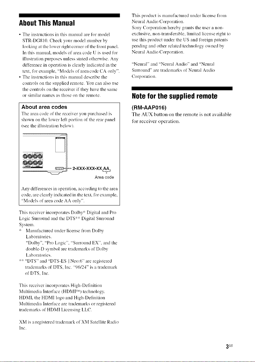
About area codes
Tile area cocle of the receiver you purchased is
shown on the lower left portion of tile rear panel
see tile illustration below).
Area code
Any differences in operation, according to tile area
code. are clearly indicated in the text. for example,
"Models of area code AA only".
This product is manufactured under license from
Neural Audio Corporation.
Sony Corporation hereby grants tile user a non-
exclusive, non-transferable, limited license right to
use this product under tile US aud foreign patents
pending and other related technology owned by
Neural Audio Corporation.
"Neural" and "Neural Audio" and "Neural
Surround" are trademarks of Neural Audio
Corporation.
Note for the supplied remote
(RM-AAP016)
The AUX button on the remote is not available
for receiver operation.
This receiver incorporates Dolby : Digital and Pro
Logic Surrouud aud tile DTS:: Digital Surround
System.
: Manufactured under license from Dolby
Laboratories.
"Dolby", "Pro Logic". "Surround EX". and the
double-D symbol are trademarks of Dolby
Laboratories.
:: "DTS" and "DTS-ES I Neo:6" are registered
trademarks of DTS. lnc. "96/24" is a trademark
of DTS. Inc.
This receiver incorporates High-Definition
Multimedia Interface (HDMI TM) technology.
HDMI. the HDMI logo aud High-Definition
Multimedia Interface are trademarks or registered
trademarks of HDMI Licensing LLC.
XM is a registered trademark of XM Satellite Radio
Inc.
3 US
Tableof Contents
Getting Started
Description and location of parts ................... 5
1: Installing speakers ................................... 15
2: Connecting speakers ................................ 16
3a: Connecting the audio components ......... 17
3b: Connecting the video components ........ 18
4: Connecting the antennas .......................... 26
5: Preparing the receiver and the remote .....27
6: Selecting the speaker system ................... 28
7: Calibrating the appropriate settings
automatically
(AUTO CALIBRATION) ....................... 29
8: Adjusting the speaker levels and
balance (TEST TONE) ........................... 34
Playback
Selecting a component ................................. 35
Listening/Watching a component ................ 37
Amplifier Operations
Navigating through menus ........................... 39
Adjusting the level (LEVEL menu) ............. 43
Adjusting the equalizer (EQ menu) ............. 44
Settings for the surround sound
(SUR menu) ............................................ 44
Settings for the tuner (TUNER menn) ......... 46
Settings for the audio (AUDIO menu) ......... 46
Settings for the video (VIDEO menu) ......... 47
Settings for the system (SYSTEM menn) ...48
Enjoying Surround Sound
Enjoying Dolby Digital and DTS surround
sound (AUTO FORMAT DIRECT) ....... 52
Selecting a pre-programmed sound field .... 54
Using only the front speakers
(2CH STEREO) ..................................... 57
Listening to the sound without any
adjnstment (ANALOG DIRECT) .......... 57
Resetting sound fields to the initial
settings ................................................... 58
Tuner Operations
Listening to FM/AM radio .......................... 58
Presetting radio stations .............................. 60
Listening to the XM Radio ......................... 63
Presetting XM Radio stations ..................... 68
Other Operations
Switching the audio inpnt mode
(INPUT MODE) .................................... 71
Enjoying the DIGITAL MEDIA PORT
(DMPORT) ............................................ 72
Listening to digital sound from other inputs
(DIGITAL ASSIGN) ............................. 75
Naming inputs ............................................. 76
Changing the display .................................. 77
Using the Sleep Timer ................................ 77
Recording using the receiver ....................... 78
Using the Remote
Progranmling the remote ............................ 79
4 Us
Additional Information
Glossary ...................................................... 84
Precautions .................................................. 86
Troubleshooting .......................................... 87
Specifications .............................................. 91
Index ........................................................... 93
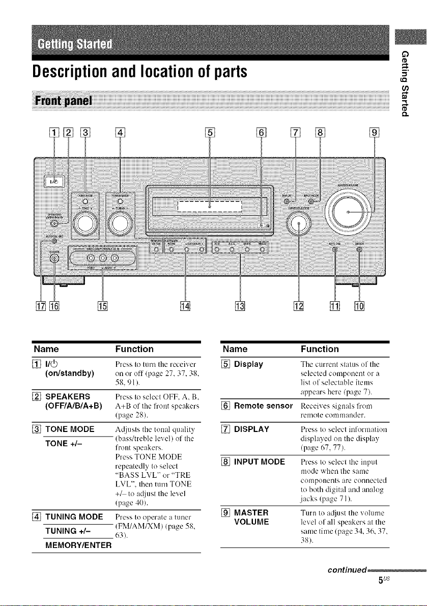
Descriptionandlocationofparts
[] []
(,Q
Name Function
[] n/_
(on/standby)
[] SPEAKERS
(OFF/A/B/A+B)
[] TONE MODE
TONE +/-
[_ITUNING MODE
TUNING +/-
MEMORY/ENTER
Press to turn the receiver
on or off/page 27.37. 38.
58.91).
Press to select OFF. A. B.
A+B of the front speakers
(pa_ze 28).
A@lsts the tonal quality
(bass/treble level) of the
front speakers.
Press TONE MODE
repeatedly to select
"BASS LVL" or "TRE
LVL". then turn TONE
+_ to a_/iust the level
(page 40).
Press to operate a tuner
(FM/AM/XM) (page 58.
63).
Name Function
[] Display The current stat/lS of the
selected component or a
list of selectable items
appears here (page 7).
[] Remote sensor Receives signals from
remote conlnlander.
[] DISPLAY Press to select information
displayed on the display
(page 67, 77).
[] INPUT MODE Press to select the input
mode when the same
components are connected
to both digital and analog
jacks (page 71).
[] MASTER Turn to adjust the volume
VOLUME level of all speakers at the
same time (page 34. 36. 37.
38).
continued,
5us
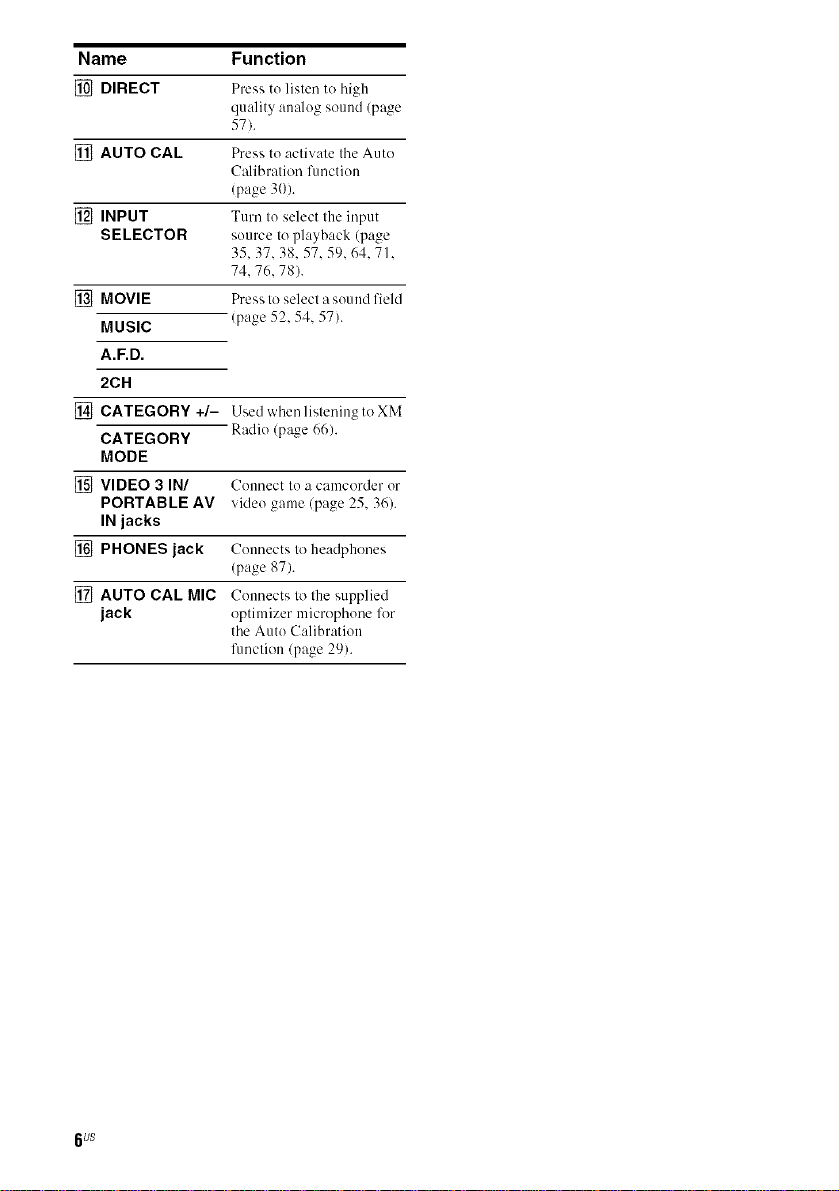
Name Function
[] DIRECT Press to listen to high
[] AUTO CAL Press to activate the Auto
[] INPUT Turn to select the input
SELECTOR source to playback (page
[] MOVIE Press to select a sound field
MUSIC (page 52, 54. 57).
A.F.D.
2CH
[] CATEGORY +/- Usedwhenlistening toXM
CATEGORY Radio (page 66).
MODE
[] VIDEO 3 IN/ Counect to a camcorder or
PORTABLE AV video game (page 25, 36).
IN jacks
[] PHONES jack Counects to headphones
[] AUTO CAL MIC Connects to the supplied
jack optimizer microphone lkw
quality analog sound (page
57).
Calibration l)mction
(page 30).
35, 37.38.57.59.64. 71.
74. 76.78).
(page 87).
the Auto Calibration
fimction/page 29).
6us
Name Function Name Function
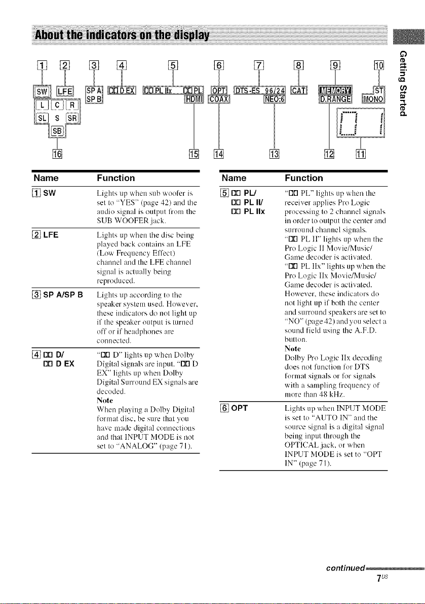
[] SW Lights up when sub woofer is [] rID PL/
[] LFE
[] SP A/SP B
[] FIO DI
I"10D EX
set to "YES" (page 42) and the Fit'1PL II/
audio signal is output lhom the rio PL IIx
SUB WOOFER .jack.
Lights up when the disc being
played back contains an LFE
(Low Frequency Effcctl
channel and the LFE channel
signal is actually being
reproduced.
Lights up according to the
speaker system used. However.
these indicators do not light up
if the speaker output is turned
off or if headphones are
connected.
"FIG D" lights tip when Dolby
Digital signals are input. "FIG D
EX" lights up when Dolby
Digital Surround EX signals are
decoded.
Note
When playing a Dolby Digit:d
format disc. be sure that you
have made digital connections
and thai INPUT MODE is not
set to "ANALOG" (page 71/.
[] OPT Lights up when INPUT MODE
"FiG PL" lights up when the
receiver applies Pro Logic
processing to 2 channel signals
in order to output the center and
surround channel signals.
"Fir1 PL II" lights up when the
Pro Logic 11Movie/Music/
Game decoder is activated.
"Fifl PL IIx" lights up when the
Pro Logic llx Movie/Music/
Game decoder is activated.
However. these indicators do
not light up if both the center
and surround speakers are set to
"NO" (page 42) and you select a
sound field using the A.F.D.
button.
Note
Dolby Pro Logic llx decoding
does not fimction for DTS
format signals or for signals
with a sampling lhequency of
more than 48 kHz.
is set to "AUTO IN" and the
source signal is a digital signal
being input through the
OPTICAL jack, or when
INPUT MODE is set to "OPT
IN" (page 71).
continued_
7us
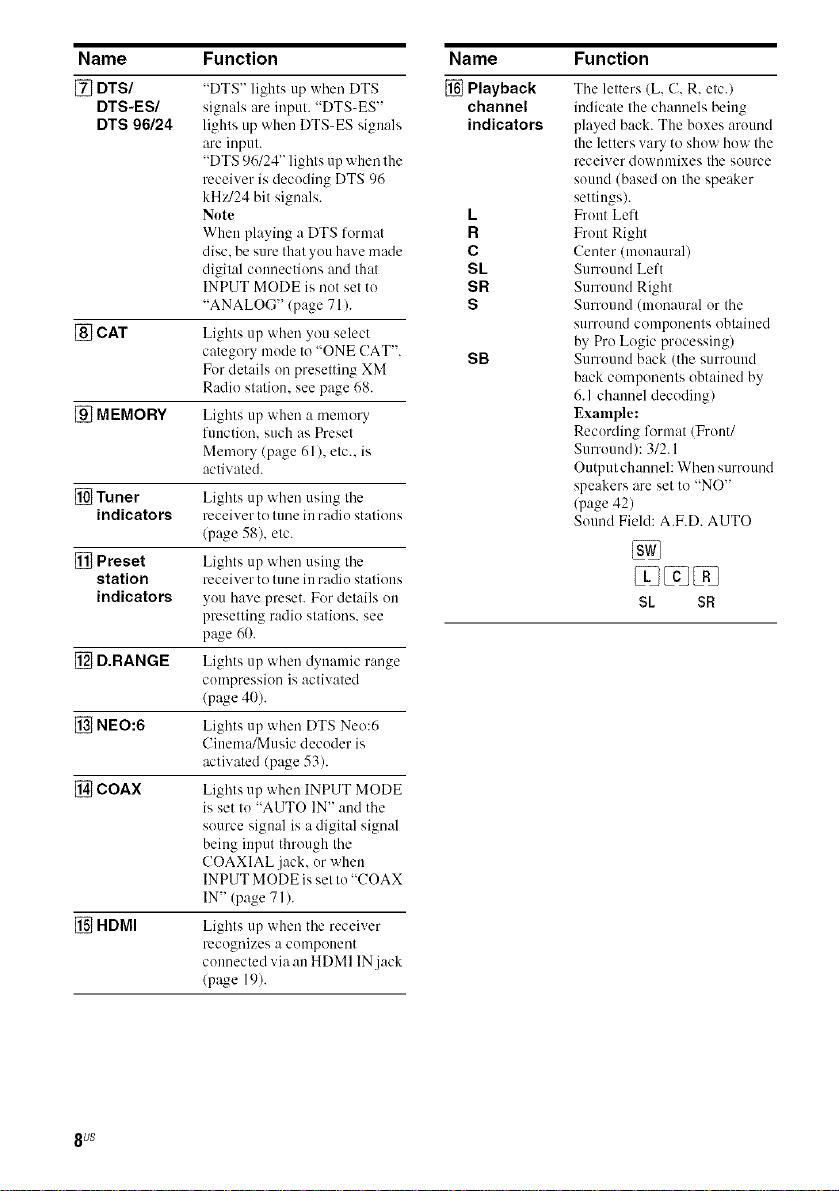
Name Function
[] DTS/
DTS-ES/
DTS 96/24
[] CAT Li_,ht_*s up when you select
[] MEMORY Lights up when a memory
[] Tuner Lights up when using the
indicators receiver to tune in radio stations
[] Preset Lieht,_*s up when using the
station receiver to tune in radio stations
indicators you have preset. For details on
[] D.RANGE Lights up when dynamic range
[] NEO:6 Lights up when DTS Neo:6
[] COAX Lights up when INPUT MODE
[] HDMI Liehl_*s up when the receiver
"DTS" lights up when DTS
signals are input. "DTS-ES"
lights up when DTS-ES signals
are input.
"DTS 96/24" lights up when the
receiver is decoding DTS 96
kHz/24 bit signals.
Note
When playing :, DTS lormat
disc. be sure that you have made
digital connections and that
INPUT MODE is not set to
"ANALOG"/page 71 ).
category mode to "ONE (!AT".
For details on presetting XM
Radio station, see page 68.
function, such as Preset
Memory (page 61), etc.. is
activated.
(page 58), etc.
presetting radio stations, see
page 60.
compression is activated
(page 40).
Cinema/Music decoder is
activated (page 53).
is set to "AUTO IN" and the
source signal is a digital signal
being input through the
COAXIAL jack, or when
INPUT MODE is set to "COAX
IN" (page 71 ).
recognizes a component
connected via an HDMI IN.jack
(p;ge 19).
Name Function
[] Playback
channel
indicators
L
R
C
SL
SR
S
SB
The letters (L, C. R. etc./
indicate the channels being
played back. The boxes around
the letters vary to show how the
receiver downmixes the source
sound (based on the speaker
settings).
Front Left
Front Right
Center (monaural)
Surround Left
Surround Right
Surround (monaural or the
surround components obtained
by Pro Logic processing)
Surround back (the surround
back components obtained by
6.1 channel decoding)
Example:
Recording format/Front/
Surround): 3/2.1
Output channel: When surround
speakers are set to "NO"
(page 42)
Sound Field: A.F.D. AUTO
SL $R
8 US
D
tD
m,
tr_
¢0
tD
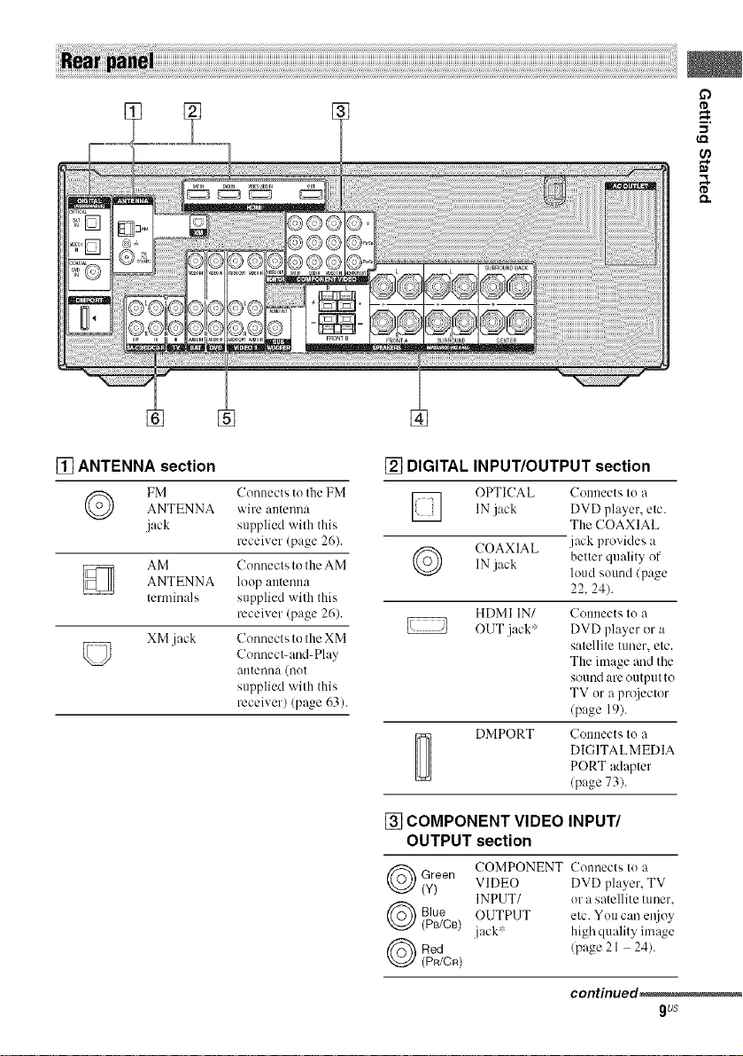
[] ANTENNA section
ANTENNA wire antenna
FM Connects to the FM
jack supplied with tiffs
AM Connects to the AM
ANTENNA loop antenna
terminals supplied with this
XM jack
receiver (page 26).
receiver (page 26).
Connects to the XM
Connect-and-Play
antenna (not
supplied with this
receiver) (page 63).
[] DIGITAL INPUT/OUTPUT section
OPTICAL Connects to a
IN jack DVD player, etc.
The COAXIAL
COAXIAL .jack provides a
IN
j_ek
belier quality of
loud sound/page
22. 24).
HDMI IN/ Connects to a
OUT jack' DVD player or a
satellite tuner, etc.
The image and the
sound are output to
TV or a projector
(page 19).
DMPORT Connects to a
DIGITALMEDIA
PORT adapter
(page 73).
[] COMPONENT VIDEO INPUT/
OUTPUT section
Green COMPONENT Connects Io a
(y) VIDEO DVD player. TV
INPUT/ or a satellite tuner.
Blue OUTPUT etc. You can el_joy
(Ps/CB) jack' highquality image
Red (page 21 24).
(PR/CR)
continued_
gus
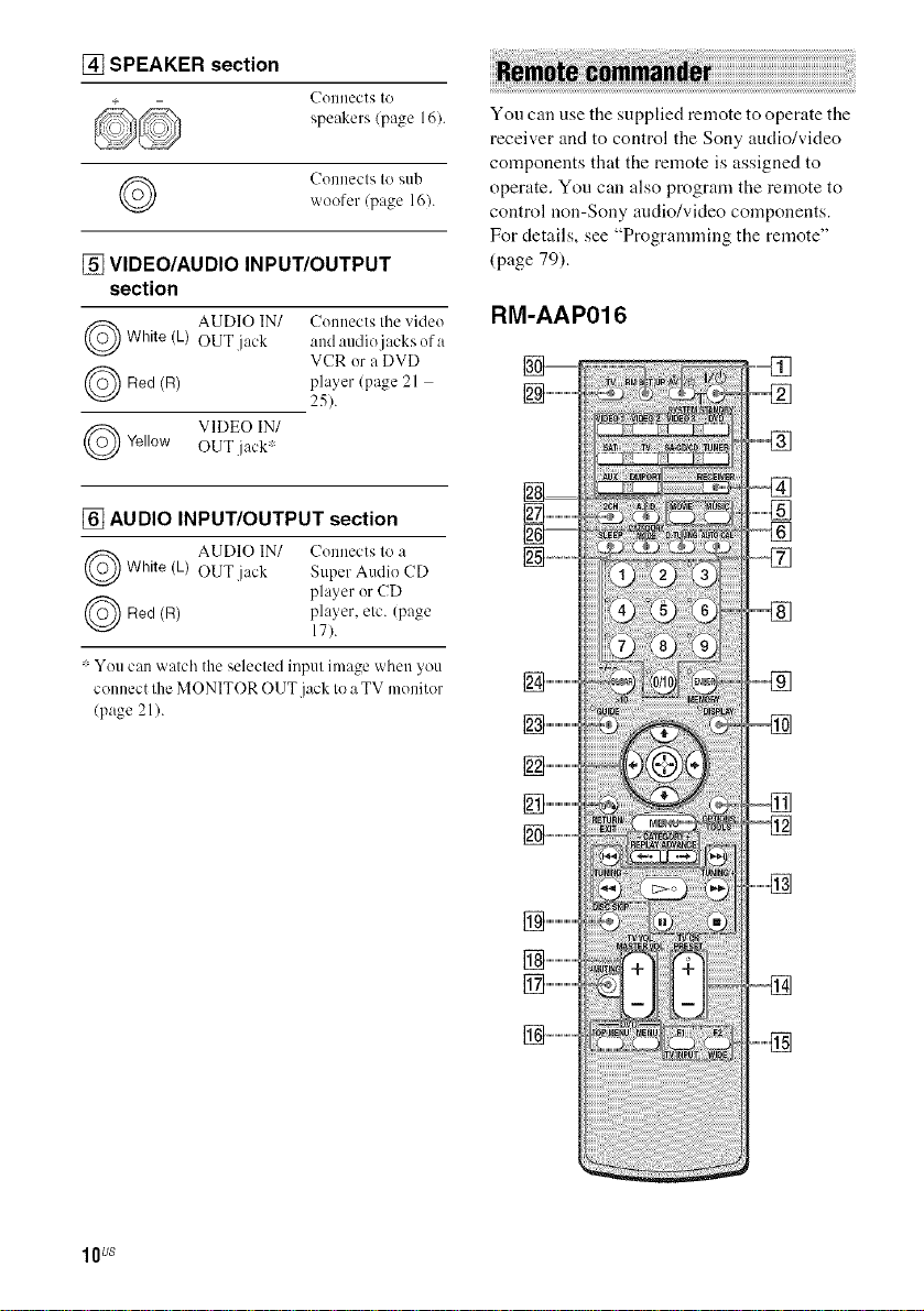
[] SPEAKER section
Celleect'_ Io
speakers (page 16).
Cennecls to sub
woofer (page 161.
[] VIDEO/AUDIO INPUT/OUTPUT
section
AUDIO IN/ Cem_ects tile videoWhite (L) OUT jack and audio jacks era
(R)
Red player (page 21
VIDEO IN/Yellow OUT jack'
[] AUDIO INPUT/OUTPUT section
VCR era DVD
25).
You can use the supplied remote to operate the
receiver and to control the Sony audio/video
components that the remote is assigned to
operate. You can also program the remote to
control non-Sony audio/video components.
For details, see "Programming the remote"
(page 79).
RM-AAP016
AUDIO IN/ Cennects 1o aWhite (k) OUT jack Super Audio CD
(R)
Red player, etc. (page
: Yeu can watch the selecled inpul image when you
connect lhe MONITOR OUT jack to aTV menitor
(page 21 ).
player er CD
17).
lOUS
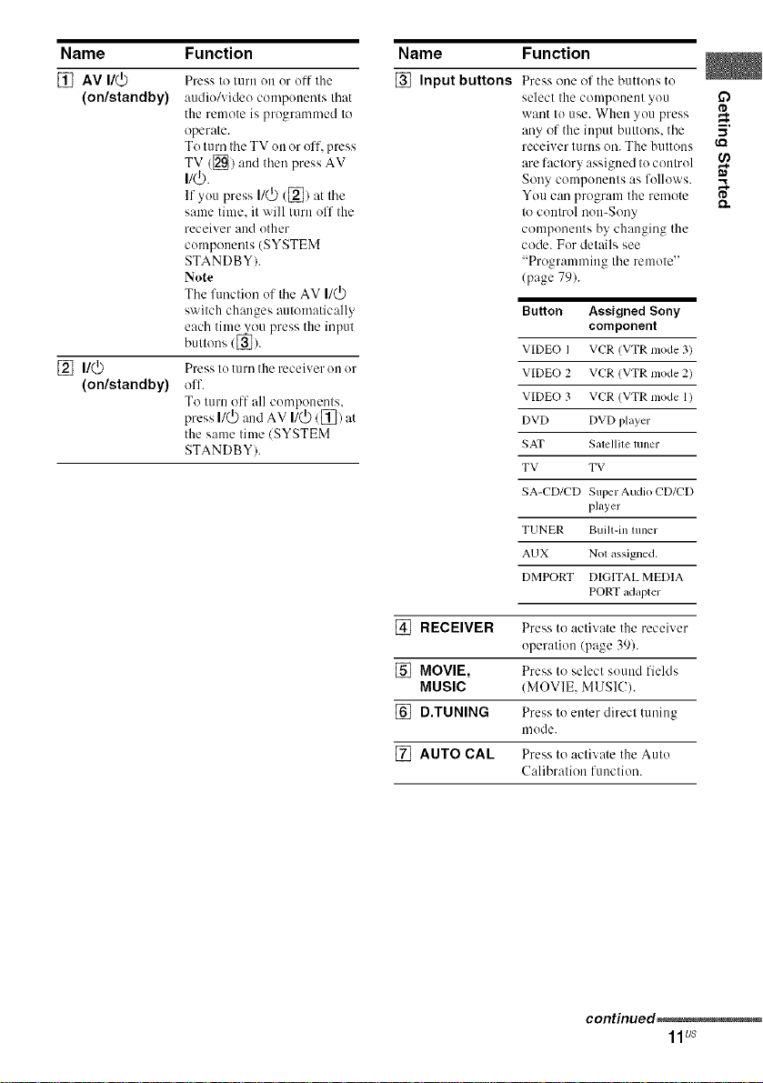
Name Function
[] AV I/(_
(on/standby)
[] n/_
(on/standby)
Press to turn on or oil- the
audio/video components that
the remote is progmn/med to
operate.
To turn the TV on or off, press
TV ([_) and thml press AV
I/_.
If yo/1 press I/(_ (_) fit the
same time. it will turn off the
receiver and other
componmlts (SYSTEM
STANDBY).
Note
Tile function of tile AV I/(_)
switch changes automatically
each time you press the input
buttons ([_).
Press to turn the receiver on or
off.
To turn off all components,
press I/(_) and AV I/(_)/[]) at
the same time (SYSTEM
STANDBY).
Name Function
[] Input buttons Press one of tile buttons to
select the component you
want to cnse. When you press
any of the input buttons, tile
receiver turns oil. The buttons
fire factory assigned to control
Sony components :is follows.
You can progmnl the rmnote
to control non-Sony
components by changing the
code. For details see
"Progmmnfing tile remote"
(page 79).
Button Assigned Sony
VIDEO I VCR (VTR mode 3)
VIDEO 2 VCR (VTR Diode 2)
VIDEO 3 VCR (VTR mode 1)
DVD DVD player
SAT Salellile tuner
TV TV
SA-CD/CD Sul)er Audio CD/CD
TUNER Built-in tuner
AUX N0I assigned.
DMPORT DIGITAL MEDIA
component
phJyer
PORT adapter
o
5'
[] RECEIVER Press to activate the receiver
operation/page 39).
[] MOVIE, Press to select sound fields
MUSIC (MOVIE, MUSIC).
[] D.TUNING Press to enter direct tuning
mode.
[] AUTO CAL Press to activate the Auto
Calibration function.
continued_
11us
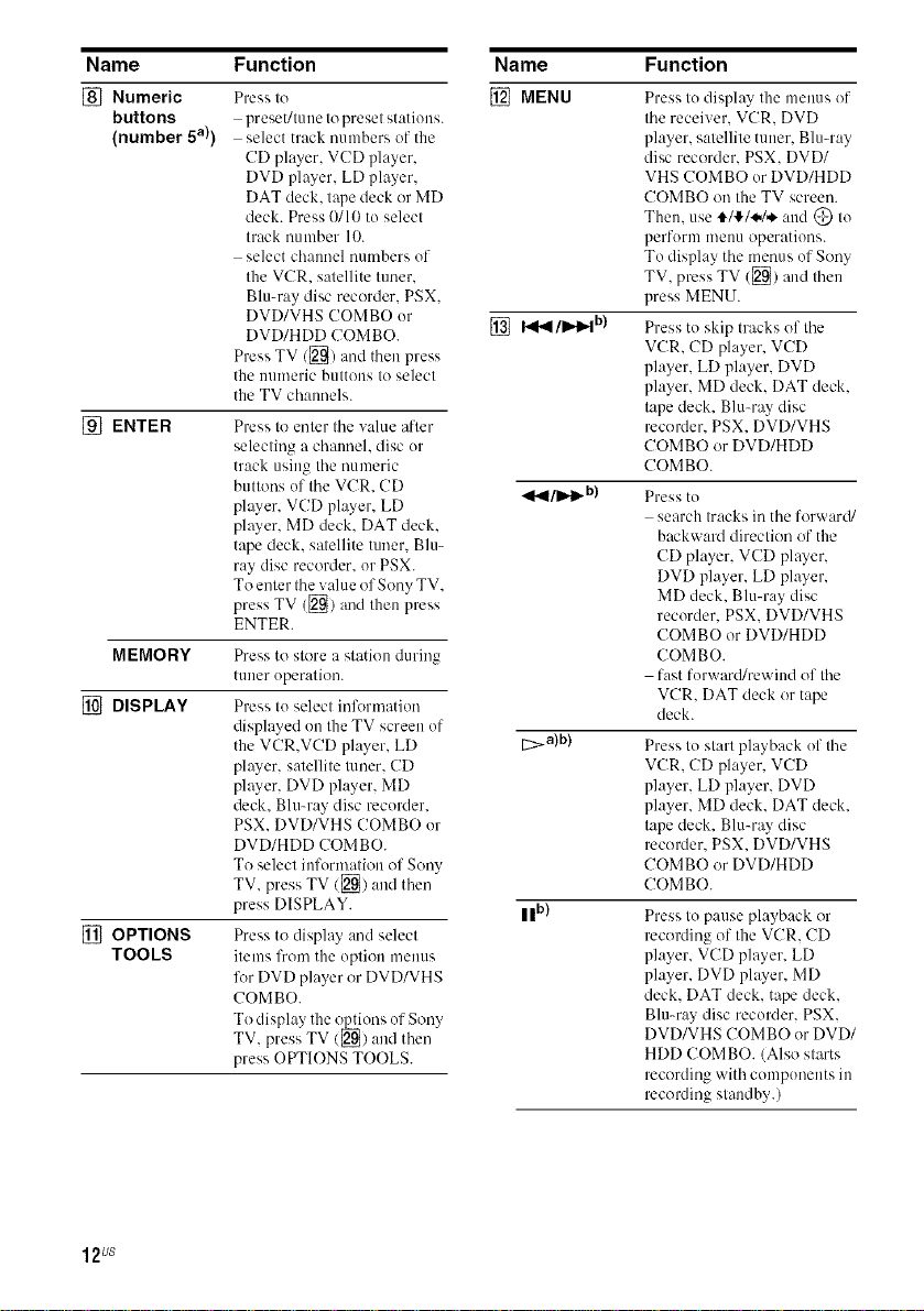
Name Function
[] Numeric
buttons
(number 5a))
[]ENTER
MEMORY
[] DISPLAY
[] OPTIONS
TOOLS
Press to
preset/tune to preset stations.
select track numbers of the
CD player, VCD player,
DVD player, LD player,
DAT deck. t@e deck or MD
deck. Press 0/lI) to select
track number 10.
select ch:umel numbers of
the VCR. satellite tuner.
Blu-ray disc recorder. PSX.
DVD/VHS COMBO or
DVD/HDD COMBO.
Press TV/[]) and then press
the nmneric buttons to select
the TV channels.
Press to enter tile value after
selecting a channel, disc or
track using tile numeric
buttons of tile VCR. CD
player, VCD player, LD
player. MD deck. DAT deck.
tape deck. satellite tuner. Blu-
ray disc recorder, or PSX.
To enter the value of Sony TV.
press TV ([]/and then press
ENTER.
Press to store a station during
tuner operation.
Press to select infl_rmation
displayed on the TV screen of
the VCR.VCD player. LD
player, satellite tuner. CD
plwer, DVD player. MD
deck. Blu-ray disc recorder.
PSX. DVD/VHS COMBO or
DVD/HDD COMBO.
To select information of Sony
TV. press TV/[_) and then
press DISPLAY.
Press to display and select
items from the option menus
lk_rDVD player or DVD/VHS
COMBO.
To display the _ons of Sony
TV, press TV/2[_/and then
press OPTIONS TOOLS.
Name Function
[] MENU
[] I_/11_ b)
_1_1/11_ b)
[_>a)b)
II b)
Press to display the menus of
tile receiver. VCR. DVD
player, satellite tuner. Blu-ray
disc recorder. PSX. DVD/
VHS COMBO or DVD/HDD
COMBO on the TV screen.
Then. use tl_l'_.l.._ and @ to
perform mellU operations.
To display tile menus of Sony
TV. press TV (_) and then
press MENU.
Press to skip tracks of the
VCR. CD player, VCD
player, LD player. DVD
player. MD deck. DAT deck.
tape deck. Blu-ray disc
recorder. PSX. DVD/VHS
COMBO or DVD/HDD
COMBO.
Press to
search tracks in the forward/
backward direction of the
CD player, VCD player,
DVD player, LD player,
MD deck. Blu-ray disc
recorder. PSX. DVD/VHS
COMBO or DVD/HDD
COMBO.
fast forward/rewind of tile
VCR. DAT deck or tape
deck.
Press to start playback of the
VCR. CD player, VCD
player, LD player. DVD
player. MD deck. DAT deck.
tape deck. Blu-ray disc
recorder. PSX. DVD/VHS
COMBO or DVD/HDD
COMBO.
Press to pause playback or
recording of the VCR. CD
player, VCD player, LD
player, DVD player. MD
deck. DAT deck. tape deck.
Blu-ray disc recorder. PSX.
DVD/VHS COMBO or DVD/
HDD COMBO. (Also starts
recording with components in
recording standby.)
12us
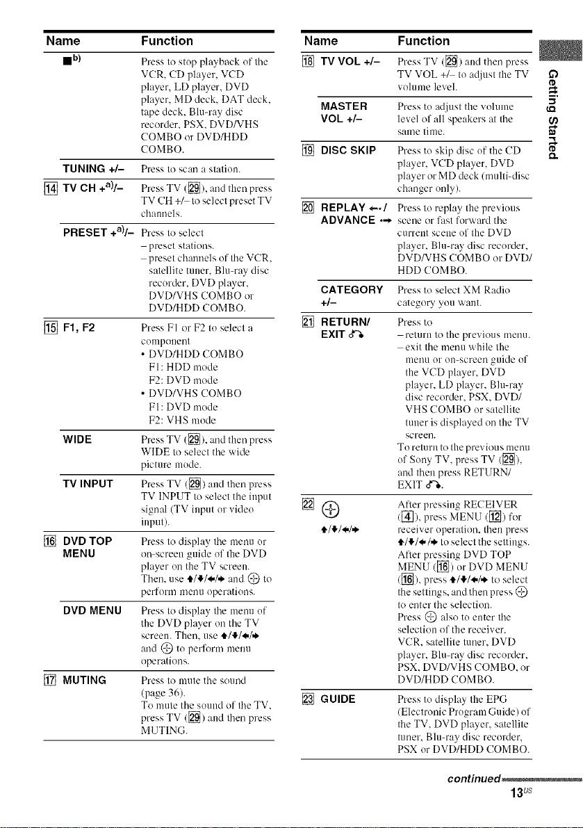
Name Function
mb)
Press to stup playback of the
VCR. CD player, VCD
player, LD player. DVD
player. MD deck. DAT deck.
tape deck. Blumay disc
recorder. PSX. DVD/VHS
COMBO or DVD/HDD
COMBO.
TUNING +/-
[] TV CH +a)/_
Press to scan a station.
Press TV ([_). and lhen press
TV CH +_ to select preset TV
chalmels.
PRESET +a)/_
Press to select
preset stations.
preset channels of the VCR.
satellite tuner. Blu-my disc
recorder. DVD player,
DVD/VHS COMBO or
DVD/HDD COMBO.
[] F1, F2
Press FI or F2 to select a
cumpouent
• DVD/HDD COMBO
FI: HDD mode
F2: DVD mode
• DVD/VHS COMBO
FI: DVD mode
F2: VHS mode
WIDE
Press TV ([_/, (-rodtiler( press
WIDE to select the wide
picture mode.
TV INPUT
Press TV ([_) aud then press
TV INPUT to select the input
signal (TV input or vide()
input).
[] DVD TOP
MENU
Press to display the menu ur
on-screen guide of the DVD
player on the TV screen.
Then. use i/!/._,/,_ and @ tu
perform meuu operations.
DVD MENU
Press to display tile mmm uf
the DVD player on tile TV
screen. Then. use t_/!/_/,,_
and @ tu perform menu
operations.
[] MUTING
Press to mute tile sound
(page 36).
To mute tile sound of tile TV.
press TV ([]) and tiler( press
MUTING.
Name Function
[] TV VOL +/- PressTV ([_) and thenpress
TV VOL +/ to a@(st the TV
volume level.
MASTER Press tu adjust the vohune
VOL +/- level of all speakers at the
same time.
[] DISC SKIP Press tu skip disc uf tile CD
player, VCD player. DVD
player or MD deck (multbdisc
changer only).
[] REPLAY *-./ Press lu replay tile previous
ADVANCE ._ scene or fast forward the
current scene uf the DVD
player, Blu-ray disc recurder.
DVD/VHS COMBO or DVD/
HDD COMBO.
CATEGORY Press to select XM Radio
+/- category yuu want.
[] RETURN/ Press to
EXIT _ return to the previous menu.
exit tile menu while the
umnu ur Ol>screen guide of
the VCD player. DVD
player, LD player, Blu-ray
disc recorder. PSX. DVD/
VHS COMBO or satellite
tuner is displayed on the TV
screen.
To return to the previous menu
of Suny TV, press TV/[_),
and then press RETURN/
EXIT o"%.
After pressing RECEIVER
/[_]). press MENU ([_) for
receiver operation, then press
,t/!/.*/.*. to select the settings.
After pressing DVD TOP
MENU ([]) ur DVD MENU
/[] ),press i/!/_,/,*, to select
tile settings, and then press @
to enter tile selection.
Press @ also tu enter Ihe
selection of the receiver.
VCR. satellite tuner. DVD
player, Blu-ray disc recurder.
PSX. DVD/VHS COMBO. or
DVD/HDD COMBO.
[] GUIDE Press tu display the EPG
/Electrouic Prugram Guide) of
the TV. DVD player, satellite
tuner. Blu-ray disc recorder.
PSX or DVD/HDD COMBO.
I'D
5'
I.Q
I'D
continued_
13Us
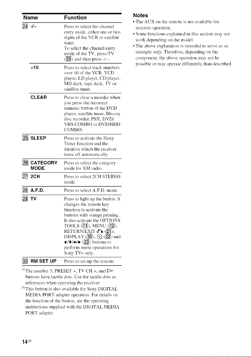
Name Function
[]4--
>10 Press to select track numbers
CLEAR Press to clear a mistake when
[] SLEEP Press to activate the Sleep
[] CATEGORY Press to select tile
MODE mode for XM radio.
[] 2CH Press to select 2CH STEREO
[] A.F.D. Press to select A.F.D. mode.
[] TV Press Io light up tile button. It
[] RM SET UP Press to set-up the remote.
a/The munber 5, PRESET +, TV CH +, and [:::>-
buttons have tactile dots. Use the tactile dots as
references when operating tile receiver.
b)This button is also available for Sony DIGITAL
MEDIA PORT adapter operation. For details on
the function of tile button, see tile operating
instructions supplied with the DIGITAL MEDIA
PORT adapter.
Press to select the channel
entry mode, either one or two
digits of the VCR or satellite
t/lIler.
To select the channel entry
mode of the TV, press TV
/[_) and then press -/--.
over 10 of the VCR. VCD
player, LD player, CD player,
MD deck. tape deck. TV or
satellite tuner.
you press tile incorrect
numeric button of tile DVD
player, satellite tuner. Blu-ray
disc recorder. PSX. DVD/
VHS COMBO or DVD/HDD
COMBO.
Timer function and the
duration which the receiver
turns off automatically.
category
mode.
changes the remote key
function to activate the
buttons with orange printing.
It also activate the OPTIONS
TOOLS ([_}), MENU ([_),
RETURN/EXIT _/[_),
DISPLAY/[_), @ (_) and
4,/I!,/4,/,*,([_) buttons to
perform menu operations for
Sony TVs only.
Notes
• Tile AUX on tile remote is not available for
receiver operation.
• Some fuoctions explained ill this section may not
work depending on the modeh
• The ahove explanation is intended to serve as all
example only. Therefore. depending on the
component, the above operation may not be
possible or may operate differently than described.
14us
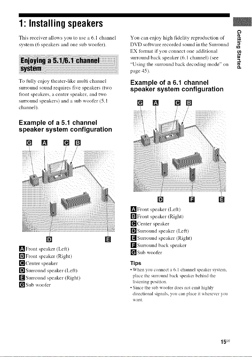
1"Installingspeakers
This receiver allows you to use a 6.1 channel
system (6 speakers and one sub woofer).
To fully enjoy theater-like multi channel
surround sound requires five speakers (two
front speakers, a center speaker, and two
surround speakers) and a sub woofer (5.1
channel).
Example of a 5.1 channel
speaker system configuration
_Front speaker (Left)
rff]Front speaker (Right)
[_Center speaker
r_Snrround speaker (Left)
[]Surround speaker (Right)
[_Snb woofer
You can enjoy high fidelity reproduction of
DVD software recorded sound in the Surround
EX format if you connect one additional
surround back speaker (6.1 channel) (see
"Using the surround back decoding mode" on
page 45).
Example of a 6.1 channel
speaker system configuration
[]
_Front speaker (Left)
[]Front speaker (Right)
[]Center speaker
[]Surround speaker (Left)
[]Surround speaker (Right)
[]Surround back speaker
_Snb woofer
Tips
• When _ou connect :_6.1 channel speaker system,
place the surround back speaker behind the
listening position.
• Since the sub woofer does not emit highly
directional signals, you can place it wherever you
want.
15us
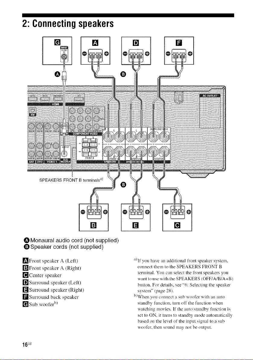
2: Connectingspeakers
[] [] [] []
SPEAKERS FRONT B terminals a)
OMonaural audio cord (not supplied)
QSpeaker cords (not supplied)
_'_Front speaker A (Left)
r_lFront speaker A (Right)
[]Center speaker
I_]Surround speaker (Left)
rlIsurround speaker (Right)
I[tSurround back speaker
[¥1 Sub woofer b)
16us
[]
a)If you have an additional front speaker system.
counect them to the SPEAKERS FRONT B
terminah You can select tile front speakers you
want to use with tile SPEAKERS (OFF/A/B/A+B)
button. For details, see "6: Selecting tile speaker
system" (page 28).
b)When you connect a sub woofer with an auto
standby function, turn off the function when
watching movies. If tile auto standby function is
set to ON. it turns to standby mode automatically
based on the level of tile input signal to a sub
woofer, then sound may not be output.
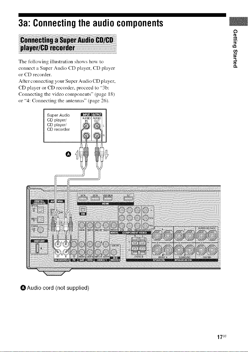
3a"Connectingtheaudiocomponents
The following illustration shows how to
connect a Super Audio CD player, CD player
or CD recorder.
After connecting your Super Audio CD player,
CD player or CD recorder, proceed to "3b:
Connecting the video components" (page 18)
or "4: Connecting the antennas" (page 26).
SuperAudio _
CD player/ _lo
CD player/
CD recorder
O
m.
ca
OAudio cord (not supplied)
17us
3b:Connectingthevideocomponents
This section describes how to hook up your
components to this receiver. BetUre you begin,
refer to "Component to be connected" below
for the pages which describe how to connect
each component.
After hooking up all your components,
pR)ceed to "4: Connecting the antennas" (page
26).
Component to be connected
Component Page
With HDMI jack 19
TV monitor 2I
DVD player/DVD recorder 22
Satellite tuneffSet4ep bex 24
VCR 25
Camcerder, vide() game, etc. 25
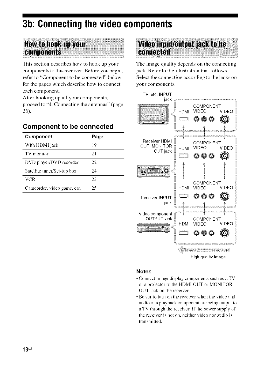
The image quality depends on the connecting
jack. Refer to the illustration that follows.
Select the connection according to the jacks on
your components.
TV, etc. INPUT
jack ................................................................................................................................................
COMPONENT
HDMI VIDEO VIDEO
..........._ @@@ (@
Receiver HDMI
OUT, MONITOR
OUT jack
COMPONENT
HDMI VIDEO VIDEO
@@@ @
COMPONENT
HDMI VIDEO VIDEO
ReceiverINPUT _ @ _ @ @
videocomponent
OUTPUT jack COMPONENT
.................. HDMI VIDEO VIDEO
' _ @@@ (@
18us
High quality image
Notes
• Connect image display components such as a TV
or a projecter to the HDMI OUT or MONITOR
OUT jack en the receiver.
• Be sur te tern on the receiver when the video and
audio af a playback component are being output te
a TV through the receiver. If the pewer supply of
the receiver is not on, neither videe nor audie is
transmitted.
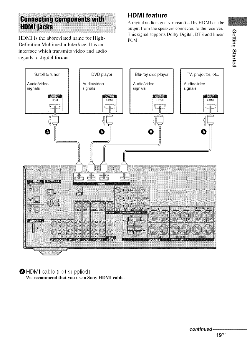
HDMI is the abbreviated name t_r High-
Definition Multimedia Interface. It is an
interface which transmits video and audio
signals in digital format.
HDMI feature
A digital :radio signals transmitted by HDMI can be
output fronl the speakers connected to tile receiver.
This signal supports Delby Digital, DTS and linear
PCM.
I,Q
D
I'D
m.
-I
,.%
I'D
Satellite tuner
Audio/video
signals
DVD player Blu-raydisc player TV, projector, etc.
Audio/video Audio/video Audio/video
signals signals signals
O O O O
O HDMI cable (not supplied)
We recr)nllnend that yOl.I I.ise a Solly HDMI cable.
continued_
19us
If you connect a Blu-ray disc
player
• Be sure to program tile VIf)EO 2 input
button on the remote so that you can use the
button to control your Blu-ray disc player.
For details, see "Programming the remote"
(page 79).
• You can also rename the VIDEO 2 input so
that it can be displayed on the receiver's
display. For details, see "Naming inputs"
(page 76).
Notes on HDMI connections
• Use a HDMI cable with tile HDMI logo
(made by Sony).
• An audio signal input to the HDMI IN jack
is output from the SPEAKERS jacks and
HDMI OUT jack. It is not output from any
other audio jacks.
• Video signals input to the HDMI IN jack can
only be output from the HDMI OUT jack.
The video input signals cannot be output
from the VIDEO OUT jacks or MONITOR
OUT jacks.
• When you want to listen to the sound from
the TV speaker, set "HDMI AUDIO" to
"TV+AMP" in the Video Settings menu
(page 47). If you connect playback multi
channel software, set to "AMP". However,
the sound will not output from the TV
speaker.
• The multi/stereo area audio signals of a
Super Audio CD are not output.
• Be sure to turn on the receiver when video
and audio signals of a playback component
are being output to a TV through this
receiver. Unless the power is on, neither
video nor audio signals will be transmitted.
• Audio signals (sampling frequency, bit
length, etc.) transmitted from an HDMI jack
may be suppressed by the connected
component. Check the setup of the
connected component if the image is poor or
the sound does not come out of a component
connected via the HDMI cable.
• Sound nmy be interrupted when the
sampling frequency or the number of
channels of audio output signals from the
playback component is switched.
• When the connected component is not
compatible with copyright protection
technology (HDCP), the image and/or the
sound from the HDMI OUT jack may be
distorted or may be not output.
In this case, check the specification of the
connected component.
• Set the resolution of the image of the
playback component to 720p or 1080i when
you output 96 kHz multi-channel sound over
a HDMI connection.
• We do not recommend using an HDMI-DVI
conversion cable. When you connect an
HDMI-DVI conversion cable to a DVI-D
component, the sound and/or the image may
not be output.
• Refer to the operating instructions of each
component connected for details.
20us
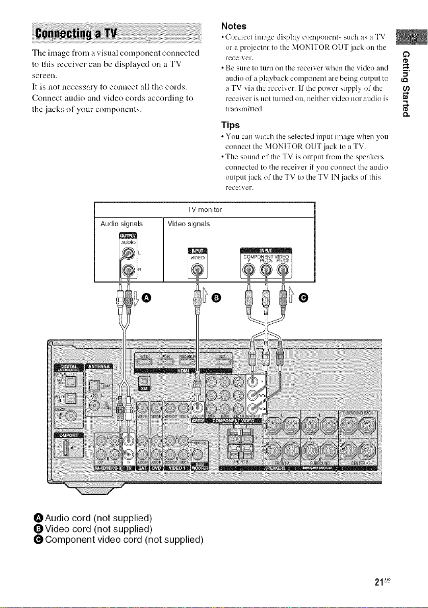
The image from a visual component connected
to this receiver can be displayed on a TV
screen.
It is not necessary to connect all the cords.
Connect audio and video cords according to
the .jacks of your components.
TV monitor
Audio signals Video signals
Notes
i
c(
nuecl ima_.e display cumponenls as a
or a projeclor to Ihe MONITOR OUT jack on the
receiver.
• Be sure I11turn on the receiver when the video and
audiu of a playback component are being uulput to
a TV via tile receiver. If the power supply 171'the O_
receiver is not turned on, neither video i1/)1"audio is m
Irausmitled. I'D
Tips
• You c:m watch the selected input image when you
connect the MONITOR OUT jack to a TV.
• The sound uf the TV is output from the speakers
connected to the receiver if you connect the audio
output jack of the TV to the TV IN.jacks of this
receiver.
such TV
m,
-,,I
_Audio cord (not supplied)
OVideo cord (not supplied)
Component video cord (not supplied)
21us
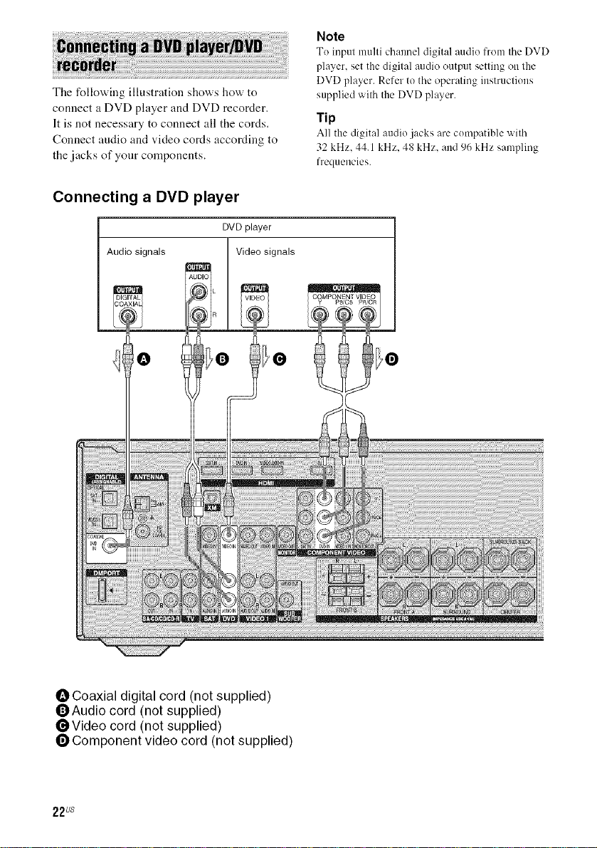
The following illustration shows how to
connect a DVD player and DVD recorder.
It is not necessary to connect all the cords.
Connect audio and video cords according to
the jacks of your components.
Connecting a DVD player
DVDplayer
Audio signals
Note
Tu input multi chaunel digital audio from tile DVD
player, set the digital audio output setting on the
DVD player. Refer to the operating instructions
supplied with the DVD player.
Tip
All the digital audio jacks are cumpatible with
32 kHz. 44.1 kHz. 48 kHz. and 96 kHz sampling
frequencies.
O Coaxial digital cord (not supplied)
OAudio cord (not supplied)
_Video cord (not supplied)
O Component video cord (not supplied)
22us
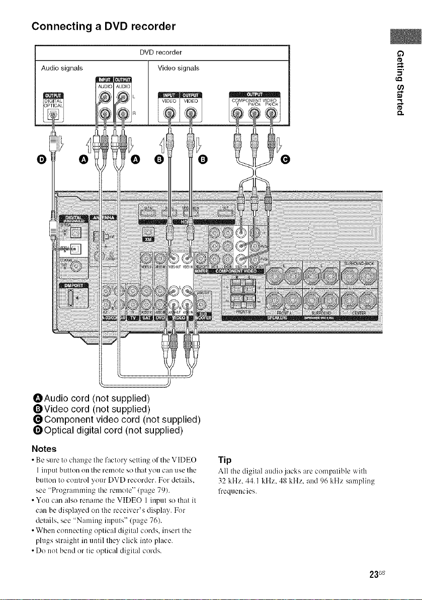
Connecting a DVD recorder
DVDrecorder
Audio signals Video signals
AUDIC _UL)IO
O
O
m.
(,el
,.%
OAudio cord (not supplied)
OVideo cord (not supplied)
_Component video cord (not supplied)
_Optical digital cord (not supplied)
Notes
• Be sure to change the factor_ setting of the VIDEO
1 input button en the remote so that you can use the
button te control your DVD recorder. For details.
see "Pregramming the remote" (page 79).
• You can also rename the VIDEO 1 input so that it
can be displayed on the receiver's display. For
details, see "Naming inputs" (page 76).
• When cennecting optical digital cords, insert the
plugs straight in until they click inte place.
• Do not bend or tie optical digital cords.
Tip
All the digit:d :radio jacks are compatible with
32 kHz. 44.1 kHz. 48 kHz. and 96 kHz sampling
frequencies.
23us
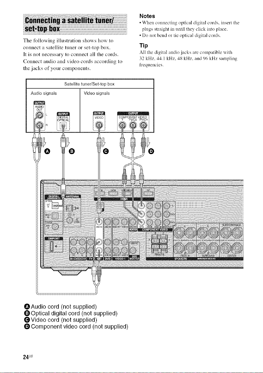
The following illustration shows how to
connect a satellite tuner or set-top box.
It is not necessary to connect all the cords.
Connect audio and video cords according to
the jacks of your components.
Satellite tuner/Set-top box
Audio signals Video signals
Notes
• When coenectiog optical digit:d cords, insert tile
plugs straight in entil they click into place.
• De not bend er tie optical digital cords.
Tip
All the digital audie jacks are compatible with
32 kHz. 44.1 kHz. 48 kHz. and 96 kHz sampling
frequencies.
OAudio cord (not supplied)
OOptical digital cord (not supplied)
OVideo cord (not supplied)
OComponent video cord (not supplied)
24us
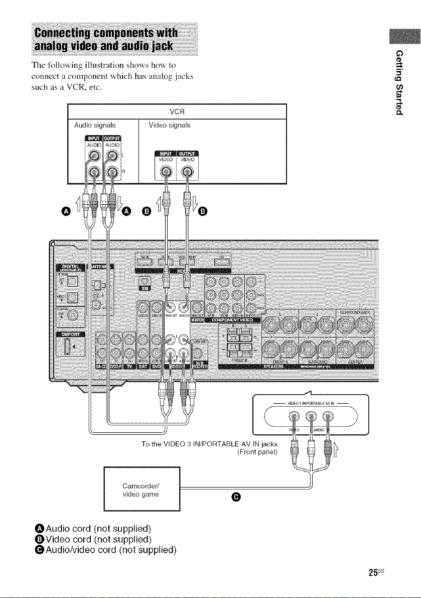
The following illustration shows how to
connect a component which has analog .jacks
such as a VCR, etc.
o
tD
m.
Audio signals Video signals
O Q
VCR
tD
To the VIDEO 3 IN/PORTABLE AV IN jacks
video game
i Camcorder/
OAudio cord (not supplied)
OVideo cord (not supplied)
_Audio/Video cord (not supplied)
(Front panel)
O
25 us
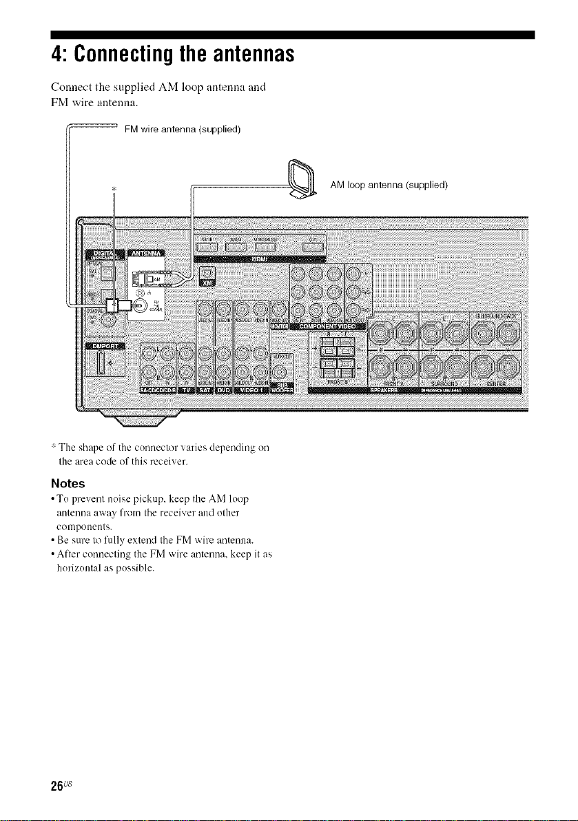
4: Connectingthe antennas
Connect the supplied AM loop untenna und
FM wire antenna.
FMwire antenna (supplied)
: The shape of the connector varies depending on
the area code of this receiver.
Notes
• Te prevent neise pickup, keep the AM loop
antenna away from the receiver aud other
conlpoeeuts.
• Be sure to fully extend the FM wire antenna.
• After connecting the FM wire antenna, keep it us
herizental as possible.
AM loop antenna (supplied)
26us
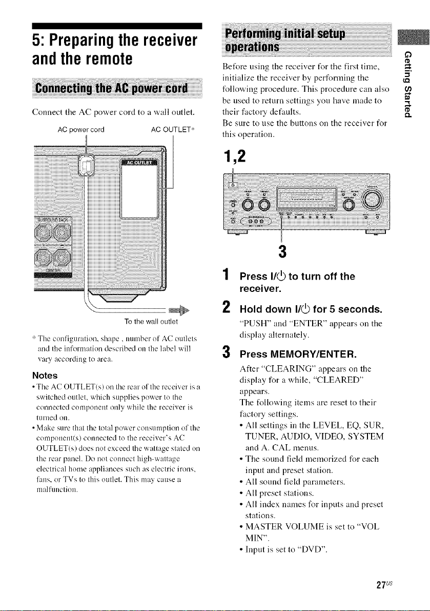
5: Preparingthereceiver
andtheremote
Connect the AC power cord to a wall outlet.
AC power cord AC OUTLET*
To the wall outlet
: The configuration, shape, number of AC outlets
and the information described on the label will
vary according to area.
Notes
• The AC OUTLET(s) on the rear of the receiver is a
switched outlet, which supplies power to the
connected component only while the receiver is
turned ou.
• Make sure that the total power consumption of the
component(s) connected to the receiver's AC
OUTLET(s) does not exceed the wattage stated on
the rear panel. Do not connect high-wattage
electrical home appliances such as electric irons.
fans. or TVs to this outlet. This may cause a
malfunction.
Before using the receiver for the first time,
initialize the receiver by performing the "_
following procedure. This procedure can also
be used to return settings you have made to "_
their factory defaults. _.
Be sure to use the buttons on the receiver for
this operation.
1,2
3
1 Press I/(_ to turn off the
receiver.
2
Hold down I/(_ for 5 seconds.
"PUSH" and "ENTER" appears on the
display alternately.
3
Press MEMORY/ENTER.
After "CLEARINC," appears on the
display for a while, "CLEARED"
appears.
The following items are reset to their
fuctory settings.
• All settings in the LEVEL, EQ, SUR,
TUNER, AUDIO, VIDEO, SYSTEM
and A. CAL menus.
• The sound field memorized for each
input and preset station.
• All sound field parameters.
• All preset stations.
• All index names for inputs and preset
stations.
• MASTER VOLUME is set to "VOL
MIN".
• Input is set to "DVD".
m,
27us
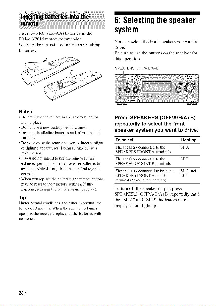
6:Selectingthe speaker
Insert two R6 (size-AA) batteries in the
RM-AAP016 remote commander.
Observe the correct polarity when installing
batteries.
Notes
• Do not leave tile remote in an extremel? hot or
humid place.
• Do not use a new battery with old ones.
• Do not mix alkaline batteries and other kinds of
batteries.
• Do not expose the remote sensor to direct sunlight
or lighting apparatuses. Doing so may cause a
malfunction.
• If you do not intend to use the remote for an
extended period of time, remove the batteries to
avoid possible damage from battery leakage and
corrosion.
• When you replace the batteries, the remote buttons
may be reset to their factory settings. If this
happens, reassign the buttons again (page 79).
rip
Under normal conditions, the batteries should last
lk_rabout 3 months. When the remote no longer
operates the receiver, replace all the batteries with
new ones.
system
You can select the front speakers you want to
drive.
Be sure to use the buttons on the receiver for
this operation.
SPEAKERS (OFF/A/B/A+B)
Press SPEAKERS (OFF/A/B/A+B)
repeatedly to select the front
speaker system you want to drive.
To select Light up
The speakers connected to the SPA
SPEAKERS FRONT A terminals
The speakers connected to the SP B
SPEAKERS FRONT B terminals
The speakers connected to both the SPA and
SPEAKERS FRONT A and B SP B
terminals/parallel connection)
To turn off the speaker output, press
SPEAKERS (OFF/A/B/A+B) repeatedly until
the "SPA" and "SP B" indicators on the
display do not light tip.
28us
7: Calibratingthe
appropriate settings
automatically
(AUTO CALIBRATION)
The DCAC (Digital Cinema Auto Calibration)
fimction allows you to perform Automatic
Calibration, such as checking the connection
between each speaker and the receiver,
adjusting the speaker level, and measuring the
distance of each speaker from your listening
position automatically. Refer also to the
"Quick Setup Guide" supplied with the
receiver.
You can also adjust the speaker levels and
balance manually. For details, see
"8: Adjusting the speaker levels and balance
(TEST TONE)" (page 34).
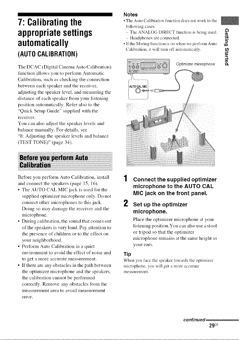
Notes
•The Auto C:dibralion functkm does not work inIlle
following cases.
The ANALOGDIRECT function is being used. i_a
Headphones are connecled.
• If the Muting function is on when we perform Auto
Calibralion. it will turn off automatically.
ca
o
£1,.
Before you perform Auto Calibration, install
and connect the speakers (page 15, 16).
• The AUTO CAL MIC jack is used for the
supplied optimizer microphone only. Do not
connect other microphones to this jack.
Doing so may damage the receiver and the
microphone.
• During calibration, the sound that comes out
of the speakers is very loud. Pay attention to
the presence of children or to the effect on
your neighborhood.
• Perform Auto Calibration in a quiet
environment to avoid the effect of noise and
to get a lnore accurate nleasurenlent.
• If there are any obstacles in the path between
the optimizer microphone and the speakers,
the calibration cannot be performed
correctly. Remove any obstacles from the
measurenlent area to avoid lneasnrenlent
error.
Connect the supplied optimizer
microphone to the AUTO CAL
MIC jack on the front panel.
2
Set up the optimizer
microphone.
Place the optinfizer microphone at your
listening position.You can also use a stool
or tripod so that the optimizer
microphone remains atthe same height as
your ears.
Tip
When youface the speaker towards the optimizer
microphone, you will get a more accurate
measurement.
continued_
29Us
 Loading...