

Sony STR-DE895B, STR-DE895S User Manual

4-244-963-12(1)
FM Stereo
FM-AM Receiver
Operating Instructions
Owner’s Record
The model and serial numbers are located at the rear of the unit. Record the serial
number in the space provided below. Refer to them whenever you call upon your Sony
dealer regarding this product.
Model No. Serial No.
STR-DE995
STR-DE895
© 2003 Sony Corporation
WARNING
To prevent fire or shock hazard, do not
expose the unit to rain or moisture.
To prevent fire, do not cover the ventilation of the
apparatus with newspapers, table-cloths, curtains,
etc. And don’t place lighted candles on the apparatus.
To prevent fire or shock hazard, do not place objects
filled with liquids, such as vases, on the apparatus.
Don’t throw away the battery with
general house waste, dispose of it
correctly as chemical waste.
Do not install the appliance in a confined space, such
as a bookcase or built-in cabinet.
For customers in the United States
This symbol is intended to alert the
user to the presence of uninsulated
“dangerous voltage” within the
product’s enclosure that may be of
sufficient magnitude to constitute a
risk of electric shock to persons.
This symbol is intended to alert the
user to the presence of important
operating and maintenance (servicing)
instructions in the literature
accompanying the appliance.
WARNING
This equipment has been tested and found to comply
with the limits for a Class B digital device, pursuant
to Part 15 of the FCC Rules. These limits are
designed to provide reasonable protection against
harmful interference in a residential installation. This
equipment generates, uses, and can radiate radio
frequency energy and, if not installed and used in
accordance with the instructions, may cause harmful
interference to radio communications. However, there
is no guarantee that interference will not occur in a
particular installation. If this equipment does cause
harmful interference to radio or television reception,
which can be determined by turning the equipment
off and on, the user is encouraged to try to correct the
interference by one or more of the following
measures:
GB
2
– Reorient or relocate the receiving antenna.
– Increase the separation between the equipment and
receiver.
– Connect the equipment into an outlet on a circuit
different from that to which the receiver is
connected.
– Consult the dealer or an experienced radio/TV
technician for help.
CAUTION
You are cautioned that any changes or modification
not expressly approved in this manual could void
your authority to operate this equipment.
Note to CATV system installer:
This reminder is provided to call CATV system
installer’s attention to Article 820-40 of the NEC that
provides guidelines for proper grounding and, in
particular, specifies that the cable ground shall be
connected to the grounding system of the building, as
close to the point of cable entry as practical.
For customers in Canada
CAUTION
TO PREVENT ELECTRIC SHOCK, DO NOT USE
THIS POLARIZED AC PLUG WITH AN
EXTENSION CORD, RECEPTACLE OR OTHER
OUTLET UNLESS THE BLADES CAN BE FULLY
INSERTED TO PREVENT BLADE EXPOSURE.
ENERGY STAR
mark.
As an ENERGY STAR® partner, Sony
Corporation has determined that this
product meets the ENERGY STAR
guidelines for energy efficiency.
This receiver incorporates Dolby* Digital and Pro
Logic Surround and the DTS** Digital Surround
System.
* Manufactured under license from Dolby
Laboratories.
“Dolby”, “Pro Logic” and the double-D symbol are
trademarks of Dolby Laboratories.
** “DTS”, “DTS-ES Extended Surround” and
“Neo:6” are trademarks of Digital Theater
Systems, Inc.
®
is a U.S. registered
®

Table of Contents
List of Button Locations and
Reference Pages
Main unit ............................................... 5
Hooking Up the Components
Required cords ....................................... 7
Antenna hookups ................................... 8
Audio component hookups .................... 9
Video component hookups .................. 10
Digital component hookups ................. 11
Multi channel input hookups ............... 13
Other hookups ..................................... 14
Hooking Up and Setting Up
the Speaker System
Speaker system hookups ..................... 17
Performing initial setup operations ..... 19
Multi channel surround setup .............. 19
Checking the connections .................... 24
Basic Operations
Selecting the component ..................... 25
Listening to the sound in another room
... 27
Changing the display ........................... 27
Enjoying Surround Sound
Using only the front speakers
(2 Channel Stereo) ........................ 28
Enjoying higher fidelity sound ............ 28
Selecting a sound field ........................ 29
Selecting the surround back decoding mode
(SURR BACK DECODING) ..........
Understanding the multi channel
surround displays .......................... 33
Customizing sound fields .................... 34
Receiving Broadcasts
Direct tuning ........................................ 37
Automatic tuning ................................. 38
Preset tuning ........................................ 38
Other Operations
Naming preset stations and program
sources ........................................... 40
31
Recording ............................................ 40
Using the Sleep Timer ......................... 41
Adjustments using the CUSTOMIZE
menu .............................................. 42
Changing the command mode of the
receiver .......................................... 43
CONTROL A1II control system ......... 44
Operations Using the Remote
RM-PP4121) and RM-PG412
2)
Before you use your remote ................ 46
Remote button description ................... 46
Selecting the command mode of the
remote ............................................ 50
Programming the remote ..................... 51
Learning the commands of your
components3)................................. 54
Performing several commands in sequence
automatically (Macro Play)3)........... 55
Operations Using the Remote
RM-LG112
4)
Before you use your remote ................ 57
Remote button description ................... 57
Selecting the command mode of the
remote ............................................ 61
Programming the remote ..................... 61
Learning the commands of your
components ................................... 64
Performing several commands in sequence
automatically (Macro Play) .............
66
Additional Information
Precautions .......................................... 67
Troubleshooting ................................... 67
Specifications ...................................... 70
Tables of settings using the MAIN
MENU button ................................ 73
Adjustable parameters for each sound
field ............................................... 75
1)
STR-DE895 models of area code CA only.
2)
STR-DE995 models of area code CA only and
STR-DE895 models of area code U, E2/E3, MX
only.
3)
RM-PG412 only.
4)
STR-DE995 models of area code U only.
GB
3
S
About This Manual
The instructions in this manual are for models
STR-DE995 and STR-DE895. Check your model
number by looking at the lower right corner of the
front panel. In this manual, the STR-DE995 is used
for illustration purposes unless stated otherwise. Any
difference in operation is clearly indicated in the text,
for example, “STR-DE995 only”.
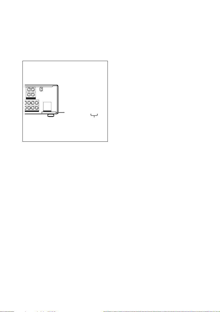
About area codes
The area code of the receiver you purchased is
shown on the lower portion of the rear panel (see
the illustration below).
LRL
– +
R
FRONT B
SPEAKERS
IMPEDANCE USE 8-16Ω
FRONT A
L
R
+ +
––
LR
SURROUND
IMPEDANCE USE 8-16Ω
Any differences in operation, according to the
area code, are clearly indicated in the text, for
example, “Models of area code AA only”.
Tip
The instructions in this manual describe the controls
on the receiver. You can also use the controls on the
supplied remote if they have the same or similar
names as those on the receiver. For details on the use
of your remote, see
• pages 46–53 for RM–PP412 (STR-DE895 models
of area code CA only).
• pages 46–56 for RM–PG412 (STR-DE995 models
of area code CA only and STR-DE895 models of
area code U, E2/E3, MX only).
• pages 57–66 for RM–LG112 (STR-DE995 models
of area code U only).
AC OUTLET
4-XXX-XXX-XX AA
Area code
Note for the supplied remote
For RM-PP412 (STR-DE895 models of
area code CA only)
The AUX, AAC BI-LING, 12 and ON
SCREEN button on the remote are not
available.
For RM-PG412 (STR-DE995 models of
area code CA only and STR-DE895
models of area code U, E2/E3, MX
only)
– (STR-DE995 only) The AAC BI-LING and
12 button on the remote are not available.
– (STR-DE895 only) The AAC BI-LING, 12
and ON SCREEN button on the remote are
not available.
For RM-LG112 (STR-DE995 models of
area code U only)
The AAC BI-LING and 12 button on the
remote are not available.
GB
4
List of Button Locations and Reference Pages
How to use page 5 and 6
Use this page to find the location of buttons that are
mentioned in the text.
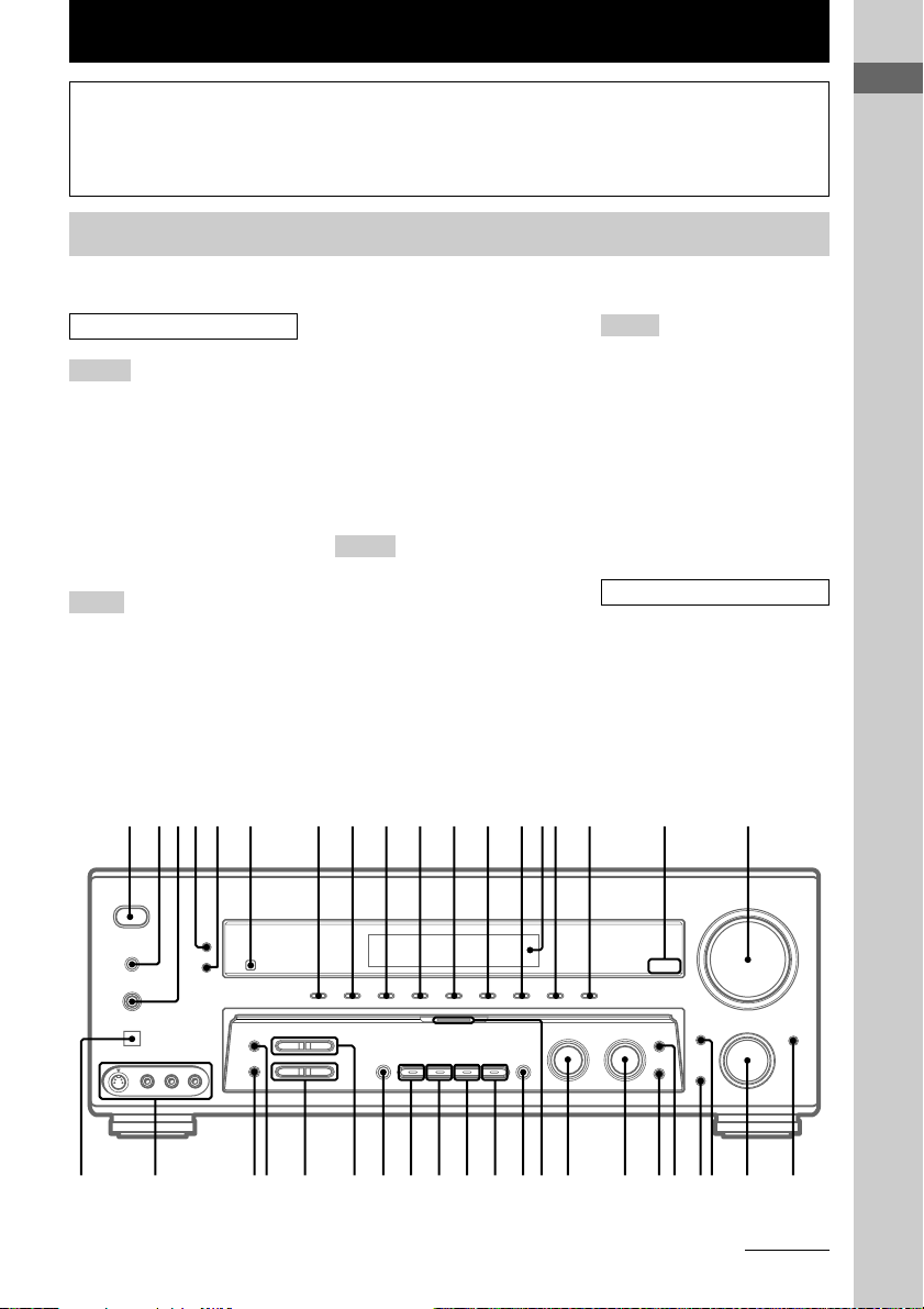
Main unit
STR-DE995 only
ALPHABETICAL ORDER
A – H
A.F.D. (button/indicator) ea
(28–31)
CD/SACD (indicator) qd (25)
DIMMER 5 (27)
DISPLAY 4 (27, 69)
Display qf (27)
DVD (indicator) q; (25)
ENTER wf (19, 40, 43)
FM MODE ej (37)
I – N
INPUT MODE ws (25)
INPUT SELECTOR w; (25)
IR (receptor) 6 (46, 57, 69)
MAIN MENU wd (20, 35, 36, 40,
42, 73)
MASTER VOLUME qk (24, 26,
67)
MD/TAPE (indicator) qs (25)
MEMORY eh (38)
MENU wh (20, 35, 36, 40, 42, 73)
MOVIE (button/indicator) e; (29,
30, 68)
MULTI CHANNEL DECODING
(indicator) wj (26)
MULTI CH IN/DIRECT wk (26)
MUSIC (button/indicator) wl (29,
30, 68)
O – S
ON SCREEN wa (10)
PHONES (jack) 3 (26, 33, 68)
PHONO (indicator) qh (25)
PRESET TUNING +/– ef (38,
39, 71)
SPEAKERS (OFF/A/B/A+B) 2
(17, 26, 67)
SURR BACK DECODING ed
(31, 42)
SURR BACK DECODING
(indicator) qj (31)
Illustration number
r
DISPLAY 4 (27, 69)
Name of button/part Reference page
R R
T – Z
TUNER FM/AM (indicator) qg
(25, 38–40)
TUNING +/– eg (38)
TV/SAT (indicator) qa (25)
VIDEO 1 (indicator) 7 (25)
VIDEO 2 (indicator) 8 (25)
VIDEO 3 (indicator) 9 (25)
VIDEO 3 DIGITAL INPUT
(OPT) (jack) el (11)
VIDEO 3 INPUT (jacks) ek (10,
11)
NUMBERS AND SYMBOLS
2CH (button/indicator) es (28,
30, 36)
2ND ZONE ql (27)
?/1 (power) 1 (19, 24, 36, 43,
71)
+/– wg (20, 35, 36, 40, 42, 73)
List of Button Locations and Reference Pages
1 2345 6 7 8 9 q; qa qs qdqfqg qh qj qk
?/1
g
qlw;wawswdwfwgwhwjwkwle;eaesefegehejekel ed
continued
GB
5
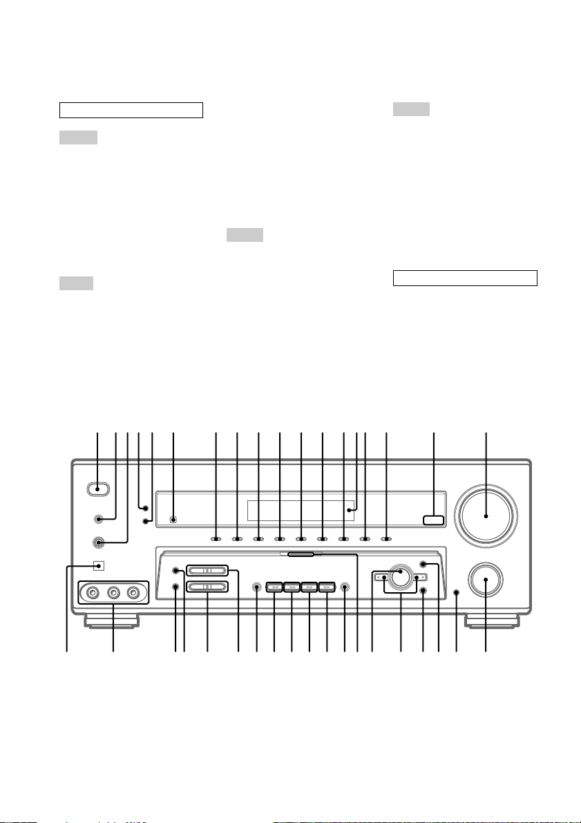
Main unit (continued)
STR-DE895 only
ALPHABETICAL ORDER
A – H
A.F.D. (button/indicator) wl
(28–31)
CD/SACD (indicator) qd (25)
DIMMER 5 (27)
DISPLAY 4 (27, 69)
Display qf (27)
DVD (indicator) q; (25)
ENTER ws (19, 40, 43)
FM MODE eg (37)
I – O
INPUT MODE w; (25)
INPUT SELECTOR ql (25)
IR (receptor) 6 (46, 57, 69)
Jog dial wf (20, 35, 36, 40, 42,
73)
MAIN MENU wa (20, 35, 36, 40,
42, 73)
MASTER VOLUME qk (24, 26,
67)
MD/TAPE (indicator) qs (25)
MEMORY ef (38)
MOVIE (button/indicator) wk (29,
30, 68)
MULTI CHANNEL DECODING
(indicator) wg (26)
MULTI CH IN/DIRECT wh (26)
MUSIC (button/indicator) wj (29,
30, 68)
P – S
PHONES (jack) 3 (26, 33, 68)
PHONO (indicator) qh (25)
PRESET TUNING +/– es (38,
39, 71)
SPEAKERS (OFF/A/B/A+B) 2
(17, 26, 67)
SURR BACK DECODING ea
(31, 42)
SURR BACK DECODING
(indicator) qj (31)
1 2345 6 7 8 9 q; qa qs qdqfqg qh qj qk
T – Z
TUNER FM/AM (indicator) qg
(25, 38–40)
TUNING +/– ed (38)
TV/SAT (indicator) qa (25)
VIDEO 1 (indicator) 7 (25)
VIDEO 2 (indicator) 8 (25)
VIDEO 3 (indicator) 9 (25)
VIDEO 3 DIGITAL INPUT
(OPT) (jack) ej (11)
VIDEO 3 INPUT (jacks) eh (10,
11)
NUMBERS AND SYMBOLS
2CH (button/indicator) e; (28,
30, 36)
?/1 (power) 1 (19, 24, 36, 43,
71)
</> wd (20, 35, 36, 40, 42, 73)
?/1
g
qlw;wawswdwfwgwhwjwkwle;eaesefegehej ed
GB
6
Hooking Up the Components
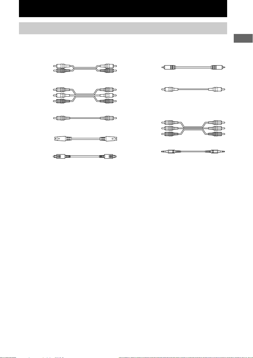
Required cords
The following optional connection cords A – I are required when you hook up the components
(pages 9 – 15).
A Audio cord (not supplied)
White (L)
Red (R)
B Audio/video cord (not supplied)
Yellow (video)
White (L/audio)
Red (R/audio)
C Video cord (not supplied)
Yellow
D S-video cord (not supplied)
E Optical digital cord (not supplied)
F Coaxial digital cord (not supplied)
G Monaural audio cord (not supplied)
Tip
Audio cord A can be torn into two monaural audio
cords G.
H Component video cord (not supplied)
I Monaural mini-plug cord (not supplied)
Black
Green
Blue
Red
Black
Before you get started
• Turn off the power to all components before making any connections.
• Do not connect the AC power cord until all of the connections are completed.
• Be sure to make connections firmly to avoid hum and noise.
• When connecting an audio/video cord, be sure to match the color-coded pins to the appropriate jacks on
the components: yellow (video) to yellow; white (left, audio) to white; and red (right, audio) to red.
• When you connect optical digital cords, insert the cord plugs straight in until they click into place.
• Do not bend or tie the optical digital cord.
Hooking Up the Components
GB
7
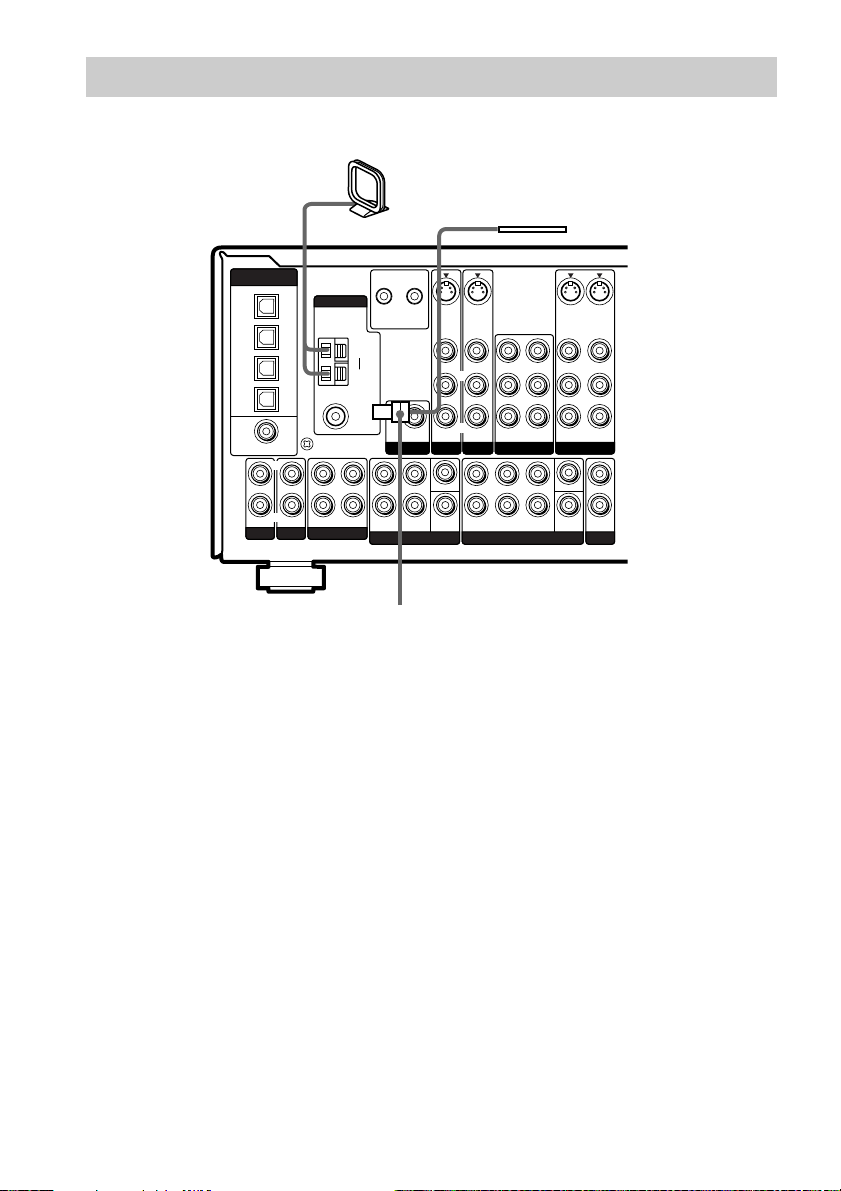
Antenna hookups
AM loop antenna
(supplied)
FM wire antenna
(supplied)
DIGITAL
(ASSIGNABLE)
OPTICAL
TV/SAT
IN
MD/
TAPE
IN
MD/
TAPE
OUT
CD/
SACD
IN
DVD
IN
COAXIAL
PHONO
* The shape of the connector varies depending on the area code.
L
R
CD/SACD
ANTENNA
y
SIGNAL GND
OUT ININ IN
MD/TAPE
CTRL S
CTRL S
S-VIDEOINS-VIDEO
STATUS
OUT
IN
VIDEO IN VIDEO IN
SUB
AUDIO IN AUDIO IN
WOOFER
PRE OUT
TV/SAT
L
CENTER
R
SUB
SURROUNDFRONT
WOOFER
MULTI CH IN 2 MULTI CH IN 1
L
R
AM
y
FM
75Ω
COAXIAL
STATUS
*
L
R
S-VIDEO
SURR
BACK
OUT
VIDEO OUT
L
R
AUDIO OUT
VIDEO 1VIDEO 2DVD
CENTER
SUB
WOOFER
S-VIDEO
IN
VIDEO IN
AUDIO IN
L
OUT
2ND ZONE
IN
VIDEO OUT
VIDEO IN
L
R
AUDIO OUT
AUDIO IN
L
L
RR
R
SURROUND
FRONT
Notes on antenna hookups
• To prevent noise pickup, keep the AM loop
antenna away from the receiver and other
components.
• Be sure to fully extend the FM wire antenna.
• After connecting the FM wire antenna, keep it
as horizontal as possible.
• Do not use the U SIGNAL GND terminal for
grounding the receiver.
GB
8
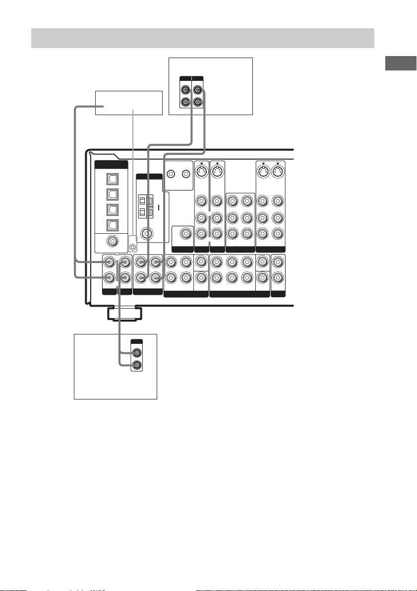
Audio component hookups
Turntable
DIGITAL
(ASSIGNABLE)
OPTICAL
TV/SAT
IN
MD/
TAPE
IN
MD/
TAPE
OUT
CD/
SACD
IN
DVD
IN
COAXIAL
PHONO
L
R
CD/SACD
ANTENNA
y
SIGNAL GND
OUT ININ IN
MD/TAPE
A
OUTPUT
LINE
CD or Super Audio
CD player
MD or Tape deck
INPUT OUTPUT
LINELLINE
ç
CTRL S
CTRL S
S-VIDEOINS-VIDEO
STATUS
OUT
IN
VIDEO IN VIDEO IN
SUB
AUDIO IN AUDIO IN
WOOFER
PRE OUT
TV/SAT
L
CENTER
R
SURROUNDFRONT
WOOFER
MULTI CH IN 2 MULTI CH IN 1
L
R
L
R
STATUS
AM
y
FM
75Ω
COAXIAL
SUB
R
AAA
ç
INOUT
S-VIDEO
SURR
BACK
OUT
VIDEO OUT
L
R
AUDIO OUT
VIDEO 1VIDEO 2DVD
CENTER
SUB
WOOFER
S-VIDEO
IN
VIDEO IN
AUDIO IN
L
OUT
2ND ZONE
IN
VIDEO OUT
L
R
VIDEO IN
L
R
AUDIO OUT
AUDIO IN
L
L
RR
R
SURROUNDFRONT
Hooking Up the Components
Note on audio component
hookups
If your turntable has a ground wire, connect it
to the U SIGNAL GND terminal.
GB
9
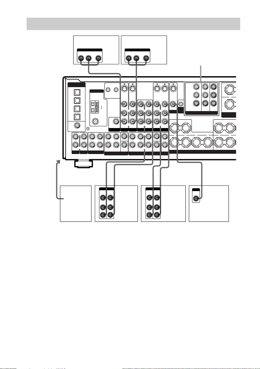
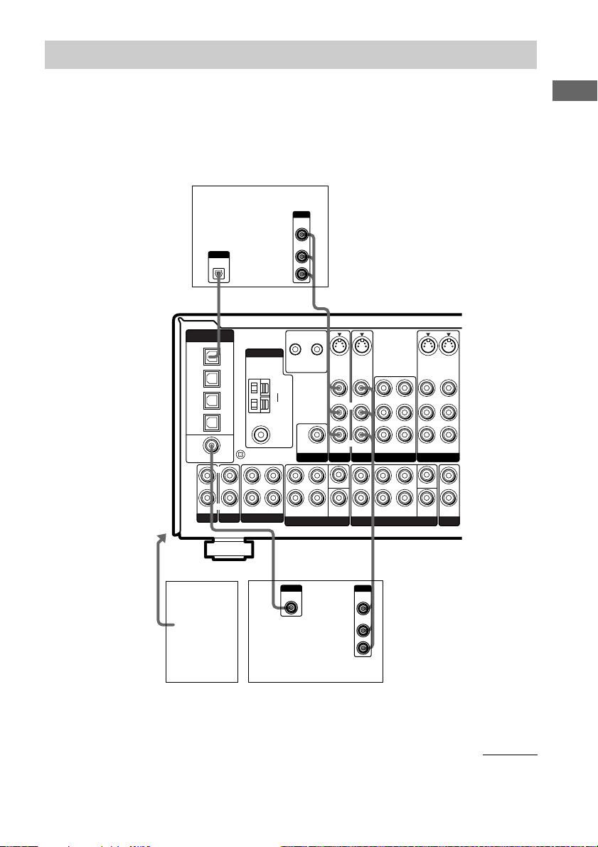
Video component hookups
K
N
N
O
To the VIDEO
3 INPUT jacks
Satellite tuner
DIGITAL
(ASSIGNABLE)
OPTICAL
TV/SAT
IN
MD/
TAPE
IN
MD/
TAPE
OUT
CD/
SACD
IN
DVD
IN
COAXIAL
L
R
PHONO
B
Camcorder
or video
game
OUTPUT
AUDIO OUT VIDEO
L
R
B
ANTENNA
y
SIGNAL GND
R
OUT ININ IN
MD/TAPE
CD/SACD
OUT
CTRL S
CTRL S
S-VIDEOINS-VIDEO
STATUS
STATUS
OUT
IN
AM
y
FM
75Ω
COAXIAL
BB
VIDEO
IN
AUDIO
IN
VIDEO IN VIDEO IN
SUB
AUDIO IN AUDIO IN
WOOFER
PRE OUT
TV/SAT
LL
CENTER
R
SUB
SURROUNDFRONT
WOOFER
MULTI CH IN 2 MULTI CH IN 1
Ç
INOUT
Ç
OUTPUTINPUT
VIDEO
OUT
AUDIO
OUT
L
R
DVD player
OUTPUT
AUDIO OUT VIDEO
L
OUT
R
B
IN
VIDEO OUT
VIDEO IN
L
L
R
R
AUDIO OUT
AUDIO IN
LRL
R
SURROUNDFRONT
BB
AUDIO
SURR
BACK
VIDEO
IN
IN
S-VIDEO
VIDEO OUT
AUDIO OUT
WOOFER
Ç
OUTPUTINPUT
VIDEO
AUDIO
OUT
VIDEO 1VIDEO 2DVD
CENTER
SUB
OUT
OUT
S-VIDEO
S-VIDEO
IN
OUT
VIDEO IN
VIDEO OUT
CTRL
L
A1 II
MONITOR
CENTER
R
AUDIO IN
+ + +
– – –
L
R
OUT
2ND ZONE
Ç
L
R
SURROUND BACK SURR
INOUT
VCRVCR
COMPONENT VIDEO
H
OUT
IMPEDANCE USE 8-16Ω
L
R
R
RLR
–
SPEA
IMPEDANCE
Y
P
B
/B—Y
P
R
/R—Y
TV/SATINDVDINMONITOR
COMPONENT VIDEO
SPEAKERS
C
INPUT
VIDEO
IN
TV monitor
FRO
FRO
* For STR-DE995, you can display the LEVEL, SET UP, EQUALIZER and CUSTOMIZE parameters and
selected sound field by pressing ON SCREEN.
Note on video component
hookups
You can connect your TV’s audio output jacks
to the TV/SAT AUDIO IN jacks on the
receiver and apply sound effects to the audio
from the TV. In this case, do not connect the
TV’s video output jack to the TV/SAT
VIDEO IN jack on the receiver. If you are
connecting a separate satellite tuner, connect
both the audio and video output jacks to the
receiver as shown above.
If you have a DVD player, TV or satellite tuner
with COMPONENT VIDEO (Y, B-Y, R-Y)
output jacks and a monitor with COMPONENT
VIDEO input jacks, use a component video
cord (not supplied) to connect to the receiver.
GB
10
Tips
• When the component is equipped with S-video
jacks, you can connect the component to the
S-video jacks on this receiver. In addition, this
receiver can convert standard video signals to
S-video signals for output from the MONITOR
OUT (S-VIDEO) jacks.
• When using the S-video jacks instead of the video
jacks, your monitor must also be connected via an
S-video jack. S-video signals are on a separate bus
from the video signals and will not be output
through the video jacks.
Notes
• (STR-DE995 only) If you make COMPONENT
VIDEO connections, nothing is displayed on the
on-screen display.
• On this receiver, the component video signals are
not compatible with S-video signals or video
signals.
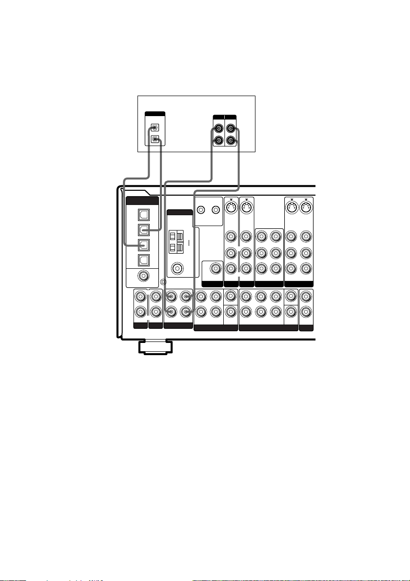
Digital component hookups
Connect the digital output jacks of your DVD player and satellite tuner (etc.) to the receiver’s digital
input jacks to bring the multi channel surround sound of a movie theater into your home. To fully
enjoy multi channel surround sound (5.1 channel), five speakers (two front speakers, two surround
speakers, and a center speaker) and a sub woofer are required. You will also need two surround back
speakers for 7.1 channel surround sound (STR-DE995 only) and a surround back speaker for 6.1
channel surround sound.
Hooking Up the Components
To the VIDEO 3
DIGITAL INPUT and
VIDEO 3 INPUT jacks
Satellite tuner
OUTPUT
DIGITAL
OPTICAL
DIGITAL
(ASSIGNABLE)
OPTICAL
TV/SAT
IN
MD/
TAPE
IN
MD/
TAPE
OUT
CD/
SACD
IN
DVD
IN
COAXIAL
L
R
PHONO
Camcorder
or video
game
CD/SACD
ANTENNA
y
SIGNAL GND
OUT ININ IN
MD/TAPE
OUTPUT
VIDEO
OUT
AUDIO
OUT
CTRL S
STATUS
OUT
AM
y
FM
75Ω
COAXIAL
WOOFER
PRE OUT
L
R
MULTI CH IN 2
F
OUTPUT
DIGITAL
COAXIAL
DVD player
(etc.)
CTRL S
STATUS
SUB
L
R
SURROUNDFRONT
L
R
BE
S-VIDEOINS-VIDEO
IN
VIDEO IN VIDEO IN
AUDIO IN AUDIO IN
TV/SAT
CENTER
WOOFER
SUB
L
R
IN
DVD
BBE
OUTPUT
VIDEO
OUT
AUDIO
OUT
S-VIDEO
S-VIDEO
OUT
IN
VIDEO OUT
VIDEO IN
VIDEO OUT
SURR
BACK
L
R
AUDIO OUT
VIDEO 1VIDEO 2
CENTER
SUB
WOOFER
VIDEO IN
AUDIO IN
L
OUT
2ND ZONE
L
R
AUDIO OUT
AUDIO IN
L
L
RR
R
SURROUNDFRONT
MULTI CH IN 1
L
R
continued
11
GB
Digital component hookups (continued)
Connect the digital output jacks of your MD or tape deck to the receiver’s digital input jack and
connect the digital input jacks of your MD or tape deck to the receiver’s digital output jack. These
connections allow you to make digital recordings of TV broadcasts, etc.
MD or tape deck
E
DIGITAL
(ASSIGNABLE)
OPTICAL
TV/SAT
IN
MD/
TAPE
IN
MD/
TAPE
OUT
CD/
SACD
IN
DVD
IN
COAXIAL
PHONO
DIGITAL
OPTICAL
IN
OUT
EA A
ç
INOUT
ç
ANTENNA
COAXIAL
y
SIGNAL GND
CD/SACD
L
R
OUT ININ IN
MD/TAPE
L
R
INPUT OUTPUT
LINELINE
L
R
ç
OUT
ç
CTRL S
CTRL S
STATUS
AM
y
FM
75Ω
S-VIDEOINS-VIDEO
OUT
WOOFER
PRE OUT
STATUS
SUB
IN
IN
VIDEO IN VIDEO IN
L
R
AUDIO IN AUDIO IN
TV/SAT
L
CENTER
R
SUB
SURROUNDFRONT
WOOFER
MULTI CH IN 2 MULTI CH IN 1
IN
S-VIDEO
S-VIDEO
OUT
IN
VIDEO OUT
VIDEO IN
VIDEO OUT
SURR
BACK
L
R
AUDIO OUT
VIDEO 1VIDEO 2DVD
CENTER
SUB
WOOFER
VIDEO IN
AUDIO IN
L
OUT
2ND ZONE
L
R
AUDIO OUT
AUDIO IN
L
L
RR
R
SURROUNDFRONT
Notes
• You cannot make digital recordings when the source is a multi channel digital source.
• All the OPTICAL and COAXIAL jacks are compatible with 96 kHz, 48 kHz, 44.1 kHz and 32 kHz sampling
frequencies.
• It is not possible to record analog signals to the components connected to MD/TAPE and VIDEO jacks with
only digital connections. To record analog signals, make analog connections. To record digital signals, make
digital connections.
• The sound is not output when you play a Super Audio CD disc on the Super Audio CD player connected to the
CD/SACD OPTICAL IN jack on this unit. Connect to the analog input jacks (CD/SACD IN jacks). Refer to the
operating instructions supplied with the Super Audio CD player.
GB
12
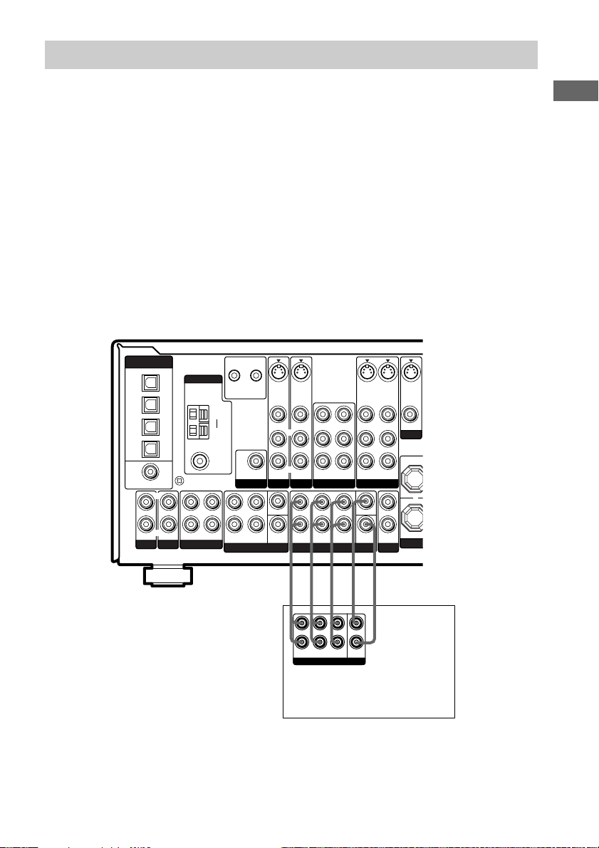
Multi channel input hookups
Although this receiver incorporates a multi channel decoder, it is also equipped with multi channel
input jacks. These connections allow you to enjoy multi channel software encoded in formats other
than Dolby Digital and DTS. If your DVD player is equipped with multi channel output jacks, you
can connect them directly to the receiver to enjoy the sound of the DVD player’s multi channel
decoder. Alternatively, the multi channel input jacks can be used to connect an external multi channel
decoder.
To fully enjoy multi channel surround sound (5.1 channel), five speakers (two front speakers, two
surround speakers, and a center speaker) and a sub woofer are required. You will also need two
surround back speakers for 7.1 channel surround sound (STR-DE995 only) and a surround back
speaker for 6.1 channel surround sound. Refer to the operating instructions supplied with your DVD
player, multi channel decoder, etc., for details on the multi channel hookups.
Notes
• When using the connections described below, adjust the level of the surround speakers and sub woofer from the
DVD player or multi channel decoder.
• See page 17 for details on speaker system hookup.
DIGITAL
(ASSIGNABLE)
OPTICAL
TV/SAT
IN
MD/
TAPE
IN
MD/
TAPE
OUT
CD/
SACD
IN
DVD
IN
COAXIAL
PHONO
L
R
CD/SACD
ANTENNA
y
SIGNAL GND
OUT ININ IN
MD/TAPE
L
R
AM
y
FM
75Ω
COAXIAL
CTRL S
CTRL S
STATUS
STATUS
OUT
IN
SUB
WOOFER
PRE OUT
L
R
SURROUNDFRONT
MULTI CH IN 2
S-VIDEOINS-VIDEO
IN
VIDEO IN VIDEO IN
L
R
AUDIO IN AUDIO IN
TV/SAT
CENTER
SUB
WOOFER
S-VIDEO
S-VIDEOINS-VIDEO
OUT
VIDEO OUT
VIDEO IN
VIDEO OUT
L
R
AUDIO OUT
AUDIO IN
AUDIO OUT
VIDEO 1VIDEO 2DVD
L
L
CENTER
RR
R
SURROUNDFRONT
MULTI CH IN 1
SURR
BACK
SUB
WOOFER
VIDEO IN
L
R
AUDIO IN
L
OUT
2ND ZONE
OUT
VIDEO OUT
MONITOR
+
Hooking Up the Components
AAAG G
L
R
FRONT
SURR
SURROUND
BACK
MULTI CH OUT
Multichannel decoder, etc.
* For STR-DE895, use G to make the connections for SURR BACK.
*
CENTER
SUB
WOOFER
DVD player,
13
GB
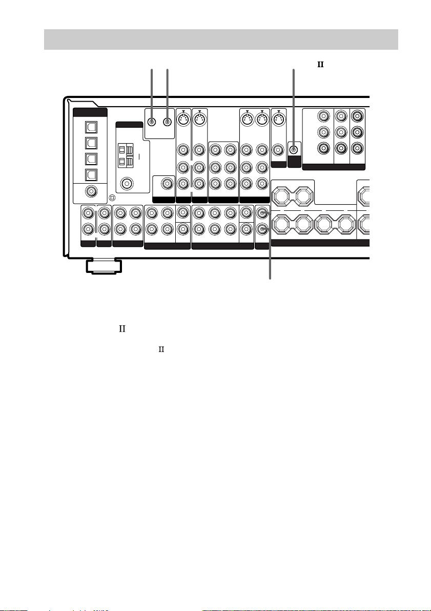
D
Other hookups
II
ç
INOUT
ç
DIGITAL
(ASSIGNABLE)
OPTICAL
TV/SAT
IN
MD/
TAPE
IN
MD/
TAPE
OUT
CD/
SACD
IN
DVD
IN
COAXIAL
PHONO
L
R
CD/SACD
ANTENNA
y
SIGNAL GND
OUT ININ IN
MD/TAPE
CTRL S
CTRL S
S-VIDEOINS-VIDEO
STATUS
OUT
IN
VIDEO IN VIDEO IN
SUB
AUDIO IN AUDIO IN
WOOFER
PRE OUT
TV/SAT
L
CENTER
R
SUB
SURROUNDFRONT
WOOFER
MULTI CH IN 2 MULTI CH IN 1
L
R
AM
y
FM
75Ω
COAXIAL
STATUS
IN
L
R
* STR-DE995 only.
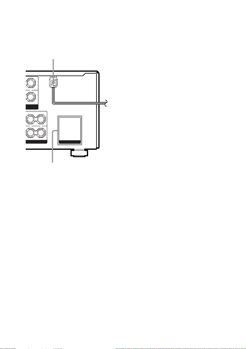
CONTROL A1 hookup
• If you have a CONTROL A1 compatible
Sony CD player, Super Audio CD player,
tape deck or MD deck
Use a monaural mini-plug cord (not
supplied) to connect the CONTROL A1II
jack on the CD player, Super Audio CD
player, tape deck or MD deck to the CTRL
A1II jack on the receiver. Refer to
“CONTROL A1II control system” on page
44 and the operating instructions supplied
with your CD player, Super Audio CD
player, tape deck or MD deck for details.
Note
If you make CONTROL A1II connections from
the receiver to an MD deck that is also connected
to a computer, do not operate the receiver while
using the “Sony MD Editor” software. This may
cause a malfunction.
CONTROL A1CONTROL S*
I
VIDEO OUT
AUDIO OUT
R
SURROUNDFRONT
VIDEO IN
L
R
AUDIO IN
LRL
SURR
BACK
S-VIDEO
OUT
VIDEO OUT
L
R
AUDIO OUT
VIDEO 1VIDEO 2DVD
CENTER
SUB
WOOFER
2ND ZONE
S-VIDEOINS-VIDEO
OUT
VIDEO IN
VIDEO OUT
MONITOR
AUDIO IN
+ + +
L
R
OUT
CTRL
A1 II
CENTER
– –
SURROUND BACK
Y
P
B
/B—Y
P
R
/R—Y
TV/SATINDVDINMONITOR
COMPONENT VIDEO
A
2ND ZONE OUT*
• If you have a Sony CD changer with a
COMMAND MODE selector
If your CD changer’s COMMAND MODE
selector can be set to CD 1, CD 2, or CD 3,
be sure to set the command mode to “CD 1”
and connect the changer to the CD jacks on
the receiver.
However, if you have a Sony CD changer
with VIDEO OUT jacks, set the command
mode to “CD 2” and connect the changer to
the VIDEO 2 jacks on the receiver.
LR
SPEAKERS
OUT
IMPE
14
GB
CONTROL S hookup
(STR-DE995 only)
When making CONTROL S hookups, use a
monaural mini-plug cord (not supplied).
CONTROL S is an original Sony control
system.
• If you connect the CONTROL S OUT jack on
another component to the CTRL S STATUS IN
jack on this receiver.
The remote sensor on the CONTROL S OUT
component receives remote codes the same way
as the remote sensor on this receiver. This is
useful if you have placed this receiver in a rack,
etc.
• If you connect the CONTROL S IN jack on
another component to the CTRL S STATUS
OUT jack on this receiver.
The remote sensor on this receiver receives
remote codes the same way as the remote
sensor on the CONTROL S IN component.
This is useful if you place the other component
away from this receiver.
2ND ZONE hookup
(STR-DE995 only)
You can use the 2ND ZONE OUT jacks to
output the audio signals of the selected
component to a stereo amplifier located in
another room (page 27).
Setting the voltage selector
If your receiver has a voltage selector on the
rear panel, check that the voltage selector is set
to the local power supply voltage. If not, use a
screwdriver to set the selector to the correct
position before connecting the AC power cord
to a wall outlet.
VOLTAGE SELECTORVOLTAGE SELECTOR
120V
240V 220V
continued
Hooking Up the Components
15
GB
K
Other hookups (continued)
Connecting the AC power
cord
AC power cord
L
+
R
T B
ERS
USE 8-16Ω
T A
L
+
–
L
UND
AC OUTLET
AC OUTLET*
* The configuration, shape, and number of AC outlets
vary according to the model and country to which
the receiver is shipped.
b
To a
wall outlet
Before connecting the AC power cord of this
receiver to a wall outlet, connect the speaker
system to the receiver (page 17).
Connect the AC power cord(s) of your audio/
video components to a wall outlet.
If you connect other audio/video components to
the AC OUTLET(s) on the receiver, the
receiver will supply power to the connected
component(s), allowing you to turn the whole
system on or off when you turn the receiver on
or off.
Caution
Make sure that the total power consumption of the
component(s) connected to the receiver’s AC
OUTLET(s) does not exceed the wattage stated on the
rear panel. Do not connect high-wattage electrical
home appliances such as electric irons, fans, or TVs
to this outlet.
GB
16
Hooking Up and Setting Up the Speaker System
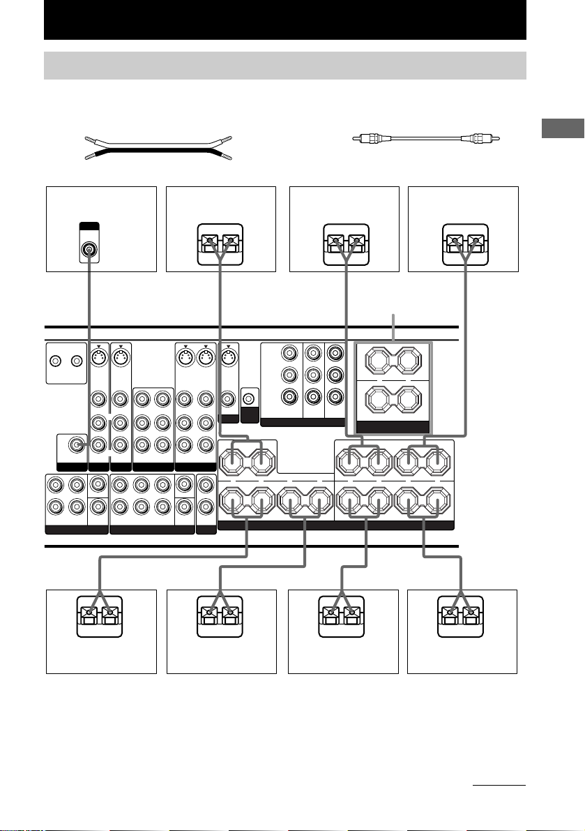
Speaker system hookups
Required cords
A Speaker cords (not supplied)
(+)
(–)
B Monaural audio cord (not supplied)
Black
Hooking Up and Setting Up the Speaker System
Active sub woofer
INPUT
AUDIO
IN
B
CTRL S
CTRL S
STATUS
S-VIDEOINS-VIDEO
STATUS
OUT
IN
SUB
WOOFER
PRE OUT
L
R
SURROUNDFRONT
MULTI CH IN 2 MULTI CH IN 1
IN
VIDEO IN VIDEO IN
L
R
AUDIO IN AUDIO IN
TV/SAT
CENTER
SUB
WOOFER
VIDEO OUT
L
R
AUDIO OUT
L
L
RR
R
SURROUNDFRONT
A
Center speaker
Ee
S-VIDEO
OUT
VIDEO IN
VIDEO OUT
VIDEO IN
L
R
AUDIO IN
AUDIO OUT
AUDIO IN
VIDEO 1VIDEO 2DVD
CENTER
SUB
SURR
WOOFER
BACK
2ND ZONE
A
S-VIDEOINS-VIDEO
OUT
VIDEO OUT
MONITOR
L
OUT
P
B
/B—Y
R
/R—Y
P
CTRL
A1 II
COMPONENT VIDEO
+ + +
– –
SURROUND BACK SURROUND
A
Front speaker A
(R)
E
Y
TV/SATINDVDINMONITOR
OUT
SPEAKERS
A
SPEAKERS
FRONT B*
L
R
SPEAKERS
IMPEDANCE USE 8-16Ω
R
IMPEDANCE USE 8-16Ω
A
–
FRONT B
FRONT ACENTER
Front speaker A
e
L
+
R
L
––
LRLR
E
+
(L)
e
A
A
E
Surround back
speaker (R)**
e
E
Surround back
speaker (L)**
e
E
Surround speaker
(R)
e
E
Surround speaker
(L)
* If you have an additional front speaker system, connect them to the SPEAKERS FRONT B terminals.
You can select the front speakers you want to use with the SPEAKERS (OFF/A/B/A+B) button (page 26).
** For STR-DE895, connect your surround back speaker to the SPEAKERS SURROUND BACK terminals.
For STR-DE995, if you connect only one surround back speaker, connect it to the SPEAKERS SURROUND
BACK L terminals.
continued
e
17
GB

Speaker system hookups (continued)
Notes
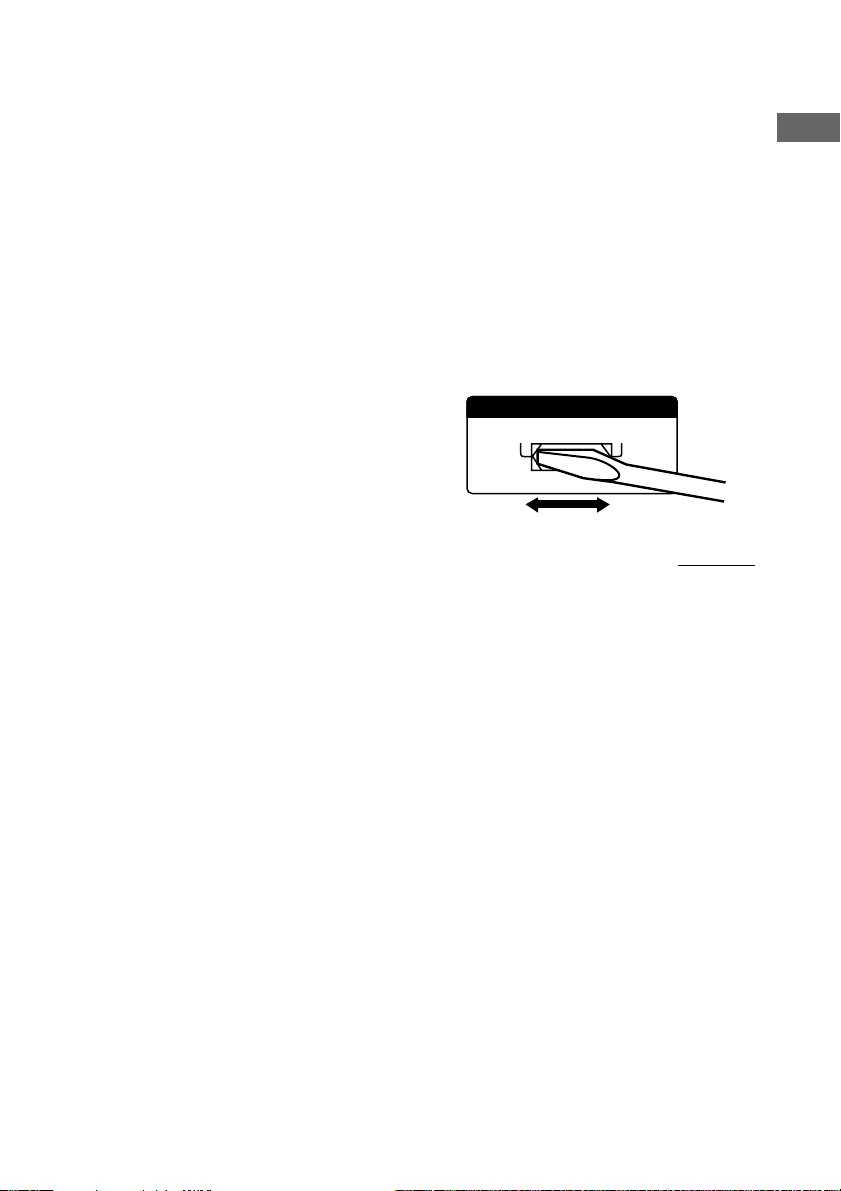
• Twist the stripped ends of the speaker cords about
10 mm (2/3 inch). Be sure to match the speaker
cord to the appropriate terminal on the components:
+ to + and – to –. If the cords are reversed, the
sound will be distorted and will lack bass.
• If you use speakers with low maximum input rating,
adjust the volume carefully to avoid excessive
output on the speakers.
To avoid short-circuiting the
speakers
Short-circuiting of the speakers may damage
the receiver. To prevent this, make sure to take
the following precautions when connecting the
speakers.
Make sure the stripped ends of each
speaker cord does not touch another
speaker terminal, the stripped end of
another speaker cord, or the metal parts of
the receiver.
Examples of poor conditions of the
speaker cord
Stripped cords are touching each other
due to excessive removal of insulation.
Stripped cords are not fully attached and
are touching the rear panel of the receiver.
After connecting all the components,
speakers, and AC power cord, output
a test tone to check that all the
speakers are connected correctly.
For details on outputting a test tone,
see page 24.
If no sound is heard from a speaker while
outputting a test tone or a test tone is output
from a speaker other than the one whose name
is currently displayed on the receiver, the
speaker may be short-circuited. If this happens,
check the speaker connection again.
Stripped speaker cord is touching another
speaker terminal.
GB
18
To avoid damaging your
speakers
Make sure that you turn down the volume
before you turn off the receiver. When you turn
on the receiver, the volume remains at the level
you turn off the receiver.
Performing initial setup
45°
90°
20°
A A
B
CC
D
operations
Once you have hooked up the speakers and
turned on the power, clear the receiver’s
memory. Then specify the speaker parameters
(size, position, etc.) and perform any other
initial setup operations necessary for your
system.
Tip
To check the audio output during settings (to set up
while outputting the sound), check the connection
(page 24).
Clearing the receiver’s
memory
Before using your receiver for the first time, or
when you want to clear the receiver’s memory,
do the following.
1 Turn off the receiver.
2 Hold down ?/1 for 5 seconds.
“ENTER to Clear” appears in the display.
3 Press ENTER.
After “MEMORY CLEARING” appears in
the display for a while, “MEMORY
CLEARED!” appears.
The following are reset to their factory
settings.
• All settings in the SET UP,
CUSTOMIZE, LEVEL and
EQUALIZER menus.
• The sound field memorized for each
INPUT SELECTOR and preset station.
• All sound field parameters.
• All preset stations.
• All index names for INPUT
SELECTOR and preset stations.
• The master volume is set to
“VOLUME MIN”.
Performing initial setup
operations
Before using your receiver for the first time,
adjust SET UP parameters so that the receiver
correspond to your system. For the adjustable
parameters, see the table on pages 73–74. See
pages 19–23 for speaker settings and pages 42–
43 for other settings.
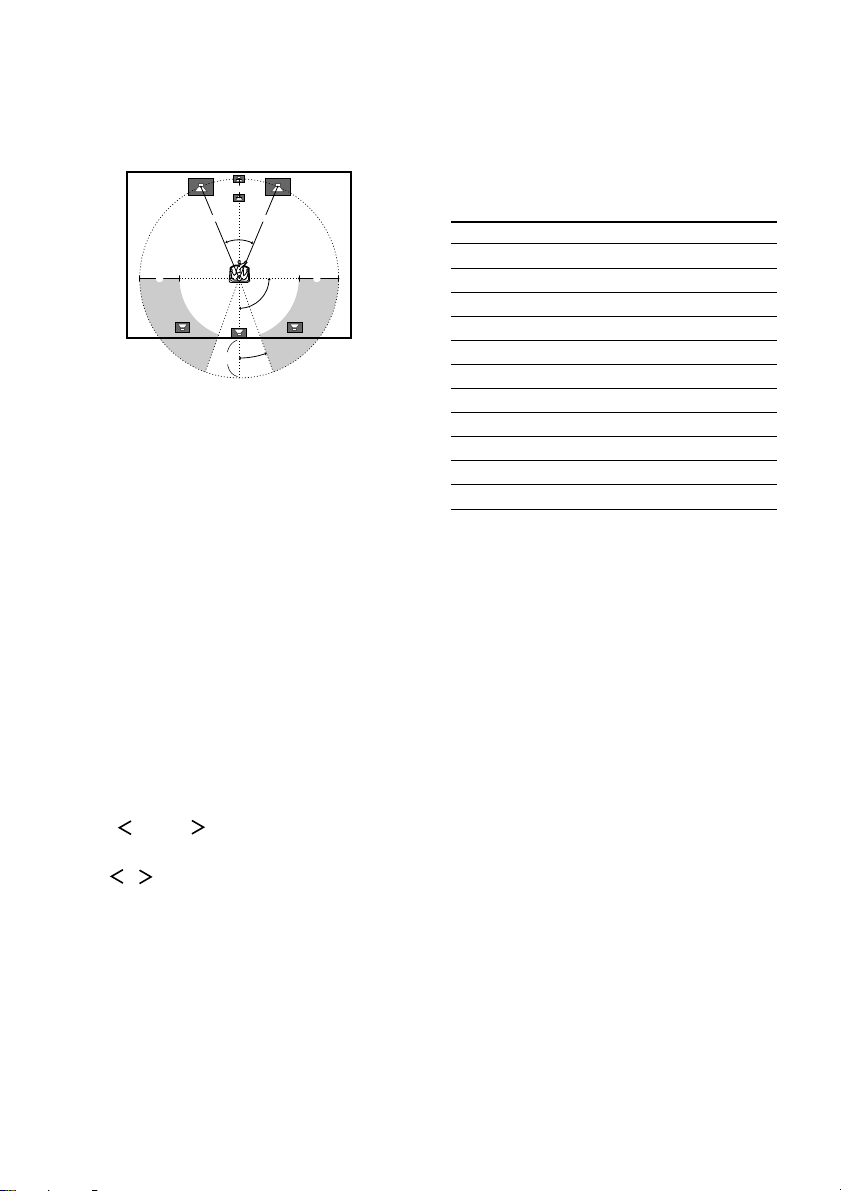
Multi channel surround
setup
For the best possible surround sound, all
speakers should be the same distance from the
listening position (A).
However, the receiver lets you place the center
speaker up to 1.5 meters (5 feet) closer (B),
the surround speakers up to 4.5 meters (15 feet)
closer (C) and the surround back speaker up to
4.5 meters (15 feet) closer (D) to the listening
position.
The front speakers can be placed from 1.0 to
7.0 meters (3 to 23 feet) from the listening
position (A).
You can place the surround speakers either
behind you or to the side, depending on the
shape of your room (etc.).
When placing surround speakers to your side
(long room)
Hooking Up and Setting Up the Speaker System
continued
GB
19
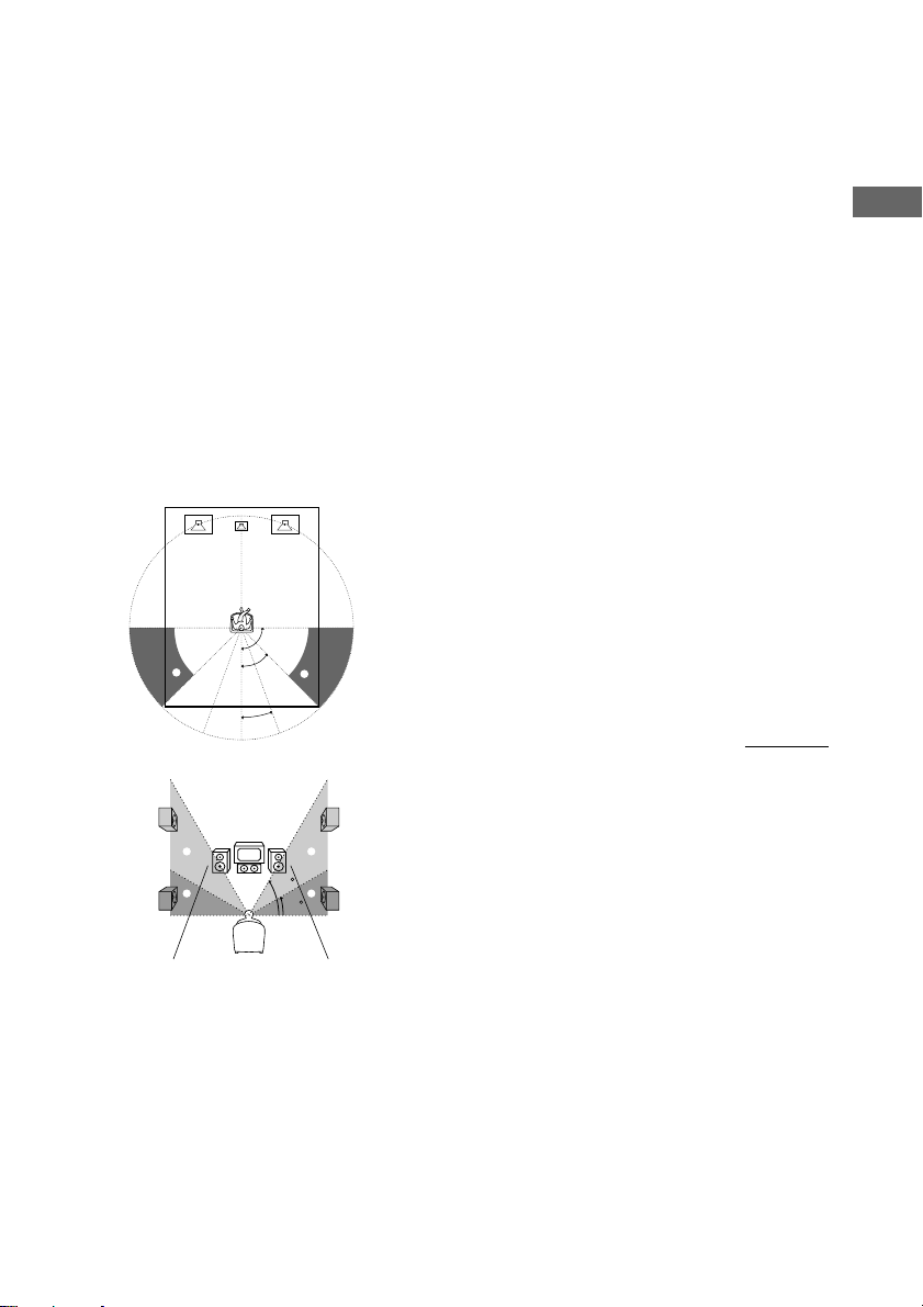
Multi channel surround setup
(continued)
When placing surround speakers behind you
Tips
• When you set up the surround back speaker, set the
speaker at least 1 meter behind the listening
position. It is recommended to place the speaker at
an equal distance from the surround left and right
speakers. If there is no space behind the listening
position, set the speaker above the listening position
by placing it on a stand or hanging it from the
ceiling. To prevent speaker damage or injury in case
the speaker falls, make sure that it is properly fixed
in place.
• Since the active sub woofer does not emit highly
directional signals, you can place it wherever you
want.
Note
Do not place the center speaker further away from the
listening position than the front speakers.
(wide room)
B
A A
45°
90°
D
20°
CC
Specifying the speaker
parameters
1 Press MAIN MENU repeatedly to select
“ SET UP ”.
2 Turn MENU (STR-DE995 only) or press
/ (STR-DE895 only) to select the
parameter you want to adjust.
Note
Some speaker settings may appear dimmed in the
display. This means that they have been changed
automatically due to other speaker settings or may
not be adjustable.
3 Turn the +/– (STR-DE995 only) or jog
dial (STR-DE895 only) to select the
setting you want.
The setting is entered automatically.
4 Repeat steps 2 and 3 until you have set
all of the parameters that follow.
Initial settings
Parameter Initial setting
SUB WOOFER [XXX] YES
FRONT SP [XXXXX] LARGE
CTR SP [XXXXX] LARGE
SURR SP [XXXXX] LARGE
SB SP [XXX] YES
SB L/R [XXX]
FRONT X.X meter (XX feet)2)3.0 meter (10 feet)
CTR X.X meter (XX feet)
SURR X.X meter (XX feet)2)3.0 meter (10 feet)
SB X.X meter (XX feet)
PL. [XXXXXXXXX] SIDE/LOW
1)
STR-DE995 only. This parameter is not available
when “Surround back speaker selection (SB SP
[XXX])” is set to “NO”.
2)
The default unit for models of area code U, CA is
“feet”.
The default unit for models of other area code is
“meter”.
x Sub woofer selection (SUB WOOFER
[XXX])
• If you connect a sub woofer, select “YES”.
• If you do not connect a sub woofer, select
“NO”. This activates the bass redirection
circuitry and outputs the LFE signals from other
speakers.
• In order to take full advantage of the Dolby
Digital bass redirection circuitry, we
recommend that you set the cut off frequency
on the sub woofer as high as possible.
1)
2)
2)
YES
3.0 meter (10 feet)
3.0 meter (10 feet)
2)
2)
2)
2)
20
GB

x Front speaker size (FRONT SP [XXXXX])
• If you connect large speakers that will
effectively reproduce bass frequencies, select
“LARGE”. Normally, select “LARGE”.
• If the sound is distorted, or you feel a lack of
surround effects when using multi channel
surround sound, select “SMALL” to activate
the bass redirection circuitry and output the
front channel bass frequencies from the sub
woofer.
• When the front speakers are set to “SMALL”,
the center and surround speakers are also
automatically set to “SMALL” (unless
previously set to “NO”).
• When the sub woofer is set to “NO”, the front
speakers are automatically set to “LARGE” and
you cannot change this setting.
x Center speaker size (CTR SP [XXXXX])
• If you connect a large speaker that will
effectively reproduce bass frequencies, select
“LARGE”. Normally, select “LARGE”.
However, if the front speakers are set to
“SMALL”, you cannot set the center speaker to
“LARGE”.
• If the sound is distorted, or you feel a lack of
surround effects when using multi channel
surround sound, select “SMALL” to activate
the bass redirection circuitry and output the
center channel bass frequencies from the front
speakers (if set to “LARGE”) or sub woofer.*
• If you do not connect a center speaker, select
“NO”. The sound of the center channel will be
output from the front speakers.*
2
x Surround speaker size (SURR SP
[XXXXX])
• If you connect large speakers that will
effectively reproduce bass frequencies, select
“LARGE”. Normally, select “LARGE”.
However, if the front speakers are set to
“SMALL”, you cannot set the surround
speakers to “LARGE”.
• If the sound is distorted, or you feel a lack of
surround effects when using multi channel
surround sound, select “SMALL” to activate
the bass redirection circuitry and output the
surround channel bass frequencies from the sub
woofer or other “LARGE” speakers.
• If you do not connect surround speakers, select
Tip
*1–*3 correspond to the following Dolby Pro Logic
modes
*1 NORMAL
*2 PHANTOM
*3 3 STEREO
“NO”.*
3
x Surround back speaker selection
(SB SP [XXX])
• If you connect surround back speaker(s), select
“YES”.
• If you do not connect surround back speaker(s),
select “NO”.
x Surround back left/right speaker
1
selection (SB L/R [XXX])*) (STR-DE995
only)
• If you connect two surround back speakers,
select “YES”.
• If you connect one surround back speaker,
select “NO”. The sound will be output from the
surround back left speaker (page 17).
* This parameter is not available when “Surround
back speaker selection (SB SP [XXX])” is set to
“NO”. When “SB SP [XXX]” is set to “NO”, “SB
L/R [XXX]” is automatically set to “NO” and you
cannot change this setting.
Hooking Up and Setting Up the Speaker System
continued
21
GB

Multi channel surround setup
(continued)
Tip
Internally, the LARGE and SMALL settings for each
speaker determine whether or not the internal sound
processor will cut the bass signal from that channel.
When the bass is cut from a channel, the bass
redirection circuitry sends the corresponding bass
frequencies to the sub woofer or other “LARGE”
speakers.
However, since bass sounds have a certain amount of
directionality, it is best not to cut them, if possible.
Therefore, even when using small speakers, you can
set them to “LARGE” if you want to output the bass
frequencies from that speaker. On the other hand, if
you are using a large speaker, but prefer not to have
bass frequencies output from that speaker, set it to
“SMALL”.
If the overall sound level is lower than you prefer, set
all speakers to “LARGE”. If there is not enough bass,
you can use the BASS parameter in the EQUALIZER
menu to boost the bass levels. To adjust the bass, see
page 36.
x Front speaker distance (FRONT X.X
meter (XX feet))
Set the distance from your listening position to
the front speakers (A on page 19).
x Center speaker distance (CTR X.X
meter (XX feet))
Set the distance from your listening position to
the center speaker. Center speaker distance
should be set from a distance equal to the front
speaker distance (A on page 19) to a distance
1.5 meters (5 feet) closer to your listening
position (B on page 19).
x Surround speaker distance (SURR X.X
meter (XX feet))
Set the distance from your listening position to
the surround speakers. Surround speaker
distance should be set from a distance equal to
the front speaker distance (A on page 19) to a
distance 4.5 meters (15 feet) closer to your
listening position (C on page 19).
x Surround back speaker distance
(SB X.X meter (XX feet))
Set the distance from your listening position to
the surround back speaker. Surround back
speaker distance should be set from a distance
equal to the front speaker distance (A on page
19) to a distance 4.5 meters (15 feet) closer to
your listening position (D on page 19).
Tip
The receiver allows you to input the speaker position
in terms of distance. However, it is not possible to set
the center speaker further than the front speakers.
Also, the center speaker cannot be set more than
1.5 meters (5 feet) closer than the front speakers.
Likewise, the surround speakers can not be set farther
away from the listening position than the front
speakers. And they can be no more than 4.5 meters
(15 feet) closer.
This is because incorrect speaker placement is not
conducive to enjoy surround sound.
Please note that, setting the speaker distance closer
than the actual location of the speakers will cause a
delay in the output of the sound from that speaker. In
other words, the speaker will sound like it is further
away.
For example, setting the center speaker distance
1~2 m (3~6 feet) closer than the actual speaker
position will create a fairly realistic sensation of being
“inside” the screen. If you cannot obtain a satisfactory
surround effect because the surround speakers are too
close, setting the surround speaker distance closer
(shorter) than the actual distance will create a larger
sound stage.
Adjusting these parameter while listening to the
sound often results in much better surround sound.
Give it a try!
22
GB
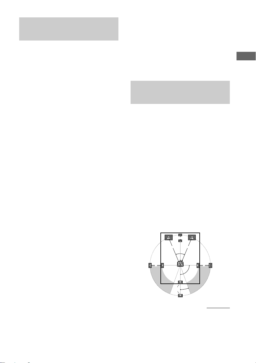
x Surround speaker placement
(PL. [XXXXXXXXX])*
This parameter lets you specify the location
and height of your surround speakers for proper
implementation of the Digital Cinema Sound
surround modes. Refer to the illustration below.
• Select “SIDE/LOW” if the location of your
surround speakers corresponds to section A
and C.
• Select “SIDE/HIGH” if the location of your
surround speakers corresponds to section A
and D.
• Select “BEHD/LOW” if the location of your
surround speakers corresponds to section B
and C.
• Select “BEHD/HIGH” if the location of your
surround speakers corresponds to section B
and D.
90°
A
B
A
45°
B
20°
Tip
The surround speaker placement parameter is
designed specifically for implementation of the
Digital Cinema Sound modes with virtual elements.
With the Digital Cinema Sound modes, speaker
placement is not as critical as other modes. All modes
with virtual elements were designed under the
premise that the surround speaker would be located
behind the listening position, but presentation remains
fairly consistent even with the surround speakers
positioned at a rather wide angle. However, if the
speakers are pointing towards the listener from the
immediate left and right of the listening position, the
sound fields with virtual elements will not be
effective unless the surround speaker position
parameter is set to “SIDE/LOW” or “SIDE/HIGH”.
Nevertheless, each listening environment has many
variables, like wall reflections, and you may obtain
better results using “BEHD/HIGH” if your speakers
are located high above the listening position, even if
they are to the immediate left and right.
Therefore, although it may result in a setting contrary
to the “Surround speaker placement” explanation, we
recommend that you playback multi channel surround
encoded software and listen to the effect each setting
has on your listening environment. Choose the setting
that provides a good sense of spaciousness and that
best succeeds in forming a cohesive space between
the surround sound from the surround speakers and
the sound of the front speakers. If you are not sure
which sounds best, select “BEHD/LOW” or
“BEHD/HIGH” and then use the speaker distance
parameter and speaker level adjustments to obtain
proper balance.
continued
Hooking Up and Setting Up the Speaker System
D
C
D
60
C
30
* These parameters are not available when
“Surround speaker size (SURR SP [XXXXX])” is
set to “NO”.
23
GB
 Loading...