

Sony SLVD-360-P Service manual
SLV-D360P/D560P
Timer indication
12-hour cycle
Timer setting
8 programs (max.)
General
Power requirements
120 V AC, 60 Hz
Power consumption
25 W
Power back-u p
Back-up duration: 0 min
Operating temperature
0°C to 45°C (32°F to 113°F)
Storage temperature
–20°C to 60°C (–4°F to 140°F)
Operating humidity
25% to 80%
Dimensions including projecting parts and controls
(w/h/d)
D560P: Approx. 430 × 85 × 294 mm
(Approx. 17 × 3 × 11 inches)
D360P: Approx. 430 × 85 × 287 mm
(Approx. 17 × 3 × 11 inches)
Mass
Approx. 3.6 kg (Approx. 7.9 lbs)
Supplied accessories
Remote commander (1)
Size AA (R6) batteries (2)
75-ohm coaxial cable with F-type connectors (1)
Design and specifications are subject to change without
notice.
385
8
383
8
RMT-V501E/V501F
SERVICE MANUAL
System
Laser
Semiconductor laser
Format
VHS NTSC standard
Video recording system
Rotary head helical scanning FM system
Video heads
Double azimuth four heads
Video signal
NTSC color, EIA standards
Tape speed
SP: 33.35 mm/s (1
EP: 11.12 mm/s ( inches/s)
LP: 16.67 mm/s (
playback only
Maximum recording/playback time
8 hrs. in EP mode (with T-160 tape)
Rewind time
Approx. 1 min (with T-120 tape)
Tuner section
Channel coverage
VHF 2 to 13
UHF 14 to 69
CATV A-8 to A-1, A to W, W+1 to W+84
Antenna
75-ohm antenna terminal for VHF/UHF
7
16
11
3
inches/s)
8
inches/s),
16
Photo: SLV-D560P
RMT-V501F
Refer to the SERVICE MANUAL of VHS MECHANICAL ADJUSTMENT MANUAL VII for MECHANICAL
ADJUSTMENTS. (9-921-790-11)
SPECIFICATIONS
Inputs and outputs
LINE IN 1 and LINE-2 IN
VIDEO IN, phono jack (1 each)
Input signal: 1 Vp-p, 75 ohms, unbalanced, sync
negative
AUDIO IN, phono jacks (2 each)
Input level: 327 mVrms
Input impedance: more than 47 kilohms
LINE OUT
VIDEO OUT, phono jack (1)
Output signal: 1 Vp-p, 75 ohms, unbalanced, sync
negative
AUDIO OUT, phono jacks (2)
Standard output: 327 mVrms
Load impedance: 47 kilohms
Output impedance: less than 10 kilohms
DIGITAL OUT
OPTICAL, Optical output jack
–18 dBm (wave length: 660 nm)
COAXIAL, phono jack
Output signal: 0.5 Vp-p, 75 ohms
COMPONENT VIDEO OUT (Y, Pb, Pr)
Phono jack
Y: 1.0 Vp-p/Pb, Pr: 0.7 Vp-p, 75 ohms
S-VIDEO OUT
4-pin, mini-DIN jack
Y: 1.0 Vp-p, unbalanced, sync negative
C: 0.286 Vp-p, load impedance 75 ohms
Timer section
Clock
Quartz locked
US Model
TS-10 MECHANISM
DVD PLAYER/
VIDEO CASSETTE RECORDER
SAFETY CHECK-OUT
After correcting the original service problem, perform the following
safety checks before releasing the set to the customer:
1. Check the area of your repair for unsoldered or poorly-soldered
connections. Check the entire board surface for solder splashes
and bridges.
2. Check the interboard wiring to ensure that no wires are “pinched”
or contact high-wattage resistors.
3. Look for unauthorized replacement parts, particularly transistors,
that were installed during a previous repair. Point them out to
the customer and recommend their replacement.
4. Look for parts which, though functioning, show obvious signs
of deterioration. Point them out to the customer and recommend
their replacement.
5. Check the line cord for cracks and abrasion. Recommend the
replacement of any such line cord to the customer.
6. Check the B+ voltage to see it is at the values specified.
7. Check the antenna terminals, metal trim, “metallized” knobs,
screws, and all other exposed metal parts for A C leakage. Check
leakage as described below.
To Exposed Metal
Parts on Set
LEAKAGE TEST
The AC leakage from any exposed metal part to earth ground
and from all exposed metal parts to any exposed metal part ha ving
a return to chassis, must not exceed 0.5 mA (500 microamperes).
Leakage current can be measured by any one of three methods.
1. A commercial leakage tester , such as the Simpson 229 or RCA
WT -540A. Follow the manufacturers' instructions to use these
instruments.
2. A battery-operated AC milliammeter. The Data Precision 245
digital multimeter is suitable for this job.
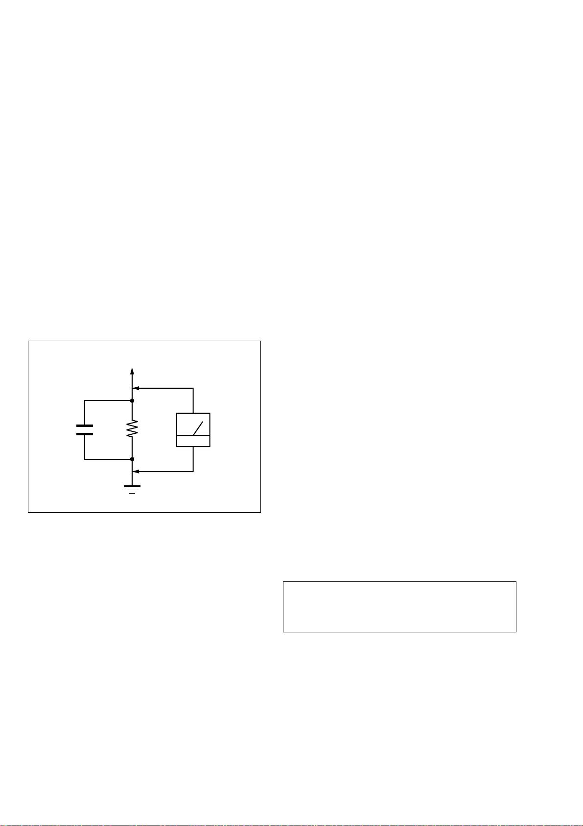
3. Measuring the voltage drop across a resistor by means of a V OM
or battery-operated AC voltmeter. The “limit” indication is
0.75V , so analog meters must hav e an accurate low-voltage scale.
The Simpson 250 and Sanwa SH-63Trd are examples of a
passive VOM that is suitable. Nearly all battery operated digital
multimeters that have a 2V A C range are suita ble. (See Fig. A)
1.5 k
0.15 µF
Fig. A. Using an AC voltmeter to check AC leakage.
Ω
Earth Ground
AC
voltmeter
(0.75 V)
WARNING!!
WHEN SERVICING, DO NO T APPRO A CH THE LASER
EXIT WITH THE EYE TOO CLOSELY. IN CASE IT IS
NECESSARY T O CONFIRM LASER BEAM EMISSION,
BE SURE TO OBSERVE FROM A DISTANCE OF
MORE THAN 25 cm FROM THE SURFACE OF THE
OBJECTIVE LENS ON THE OPTICAL PICK-UP BLOCK.
SAFETY-RELATED COMPONENT WARNING!!
COMPONENTS IDENTIFIED BY MARK 0 OR DOTTED
LINE WITH MARK 0 ON THE SCHEMATIC DIAGRAMS
AND IN THE PARTS LIST ARE CRITICAL TO SAFE
OPERATION. REPLACE THESE COMPONENTS WITH
SONY PARTS WHOSE PART NUMBERS APPEAR AS
SHOWN IN THIS MANUAL OR IN SUPPLEMENTS
PUBLISHED BY SONY.
CAUTION:
The use of optical instrument with this product will increase eye
hazard.
CAUTION
Use of controls or adjustments or performance of procedures
other than those specified herein may result in hazardous
radiation exposure.
— 2 —

TABLE OF CONTENTS
Precautions
1 Safety Precautions ······························································ 4
2 Servicing Precautions ························································ 6
3 ESD Precautions································································· 7
4 Handling the Optical Pick-up ·············································8
5 Pick-up Disassembly and Reassembly ······························ 9
2-6 DVD Deck
2-6-1 Holder Chuck Removal ················································2-22
2-6-2 Tray Disc Removal·······················································2-23
2-6-3 Ass’y P/U Deck Removal ············································ 2-24
2-6-4 Ass’y Housing Removal···············································2-25
2-6-5 Ass’y Bracket Deck Removal ······································2-26
1. General
Getting Started·································································1-1
Basic Operations······························································1-7
Advanced Hookups ·······················································1-15
DVD Settings and Adjustments ·····································1-16
DVD Additional Operations ··········································1-18
VCR Additional Operations ··········································1-24
Additional Information·················································· 1-27
2. Disassembly and Reassembly
2-1 Cabinet and PCB
2-1-1 Cabinet Top Remov al·····················································2-1
2-1-2 Bottom Cover Removal··················································2-1
2-1-3 Ass’y Front Panel Removal············································2-1
2-1-4 Function PCB Removal··················································2-1
2-1-5 Chassis Removal ····························································2-2
2-1-6 VCR Main PCB Removal ··············································2-2
2-2 Circuit Board Locations ················································· 2-3
2-3 VCR Deck Parts Locations
2-3-1 Top V ie w ········································································ 2-4
2-3-2 Bottom View···································································2-6
2-4 VCR DECK
2-4-1 Holder FL Cassette Ass’y Removal ·······························2-7
2-4-2 Lever FL Arm Ass’y Removal ·······································2-7
2-4-3 Lever FL Door Removal ················································2-8
2-4-4 Slider FL Drive, Gear FL Cam Removal ·······················2-8
2-4-5 Gear Worm Wheel Removal··········································· 2-9
2-4-6 Cable Flat Removal ························································2-9
2-4-7 Motor Loading Ass’y Removal····································2-10
2-4-8 Bracket Gear, Gear Joint 2, 1 Removal························2-10
2-4-9 Gear Loading Drive, Slider Cam,
Lever Load S, T Ass’y Removal ··································2-11
2-4-10Gear Loading Drive, Slider Cam,
Lever Load S, T Ass’y Assembly·································2-11
2-4-11Lever Pinch Drive, Lever Tension Drive Removal·······2-12
2-4-12Lever Tension Ass’y, Band Brake Ass’y Removal ·······2-12
2-4-13Lever Brake S, T Ass’y Removal ·································2-13
2-4-14Gear Idle Ass’y Removal ·············································2-13
2-4-15Disk S, T Reel Removal ···············································2-14
2-4-16Holder Clutch Ass’y Removal······································2-14
2-4-17Lever Up Down Ass’y, Gear Center Ass’y Removal ···2-15
2-4-18Guide Cassette Door Removal ·····································2-15
2-4-19Lever Unit Pinch Ass’y, Plate Joint,
Spring Pinch Drive Removal ········································2-16
2-4-20Lever #9 Guide Ass’y Removal ···································2-16
2-4-21FE Head Removal ························································ 2-17
2-4-22ACE Head Removal ····················································· 2-17
2-4-23Slider S, T Ass’y Removal ···········································2-18
2-4-24Plate Ground Deck, Cylinder Ass’y Removal··············2-18
2-4-25Hook Capstan, Belt Pulley Removal ····························2-19
2-4-26Motor Capstan Ass’y Removal ····································2-19
2-4-27Post #8 Guide Ass’y Removal······································2-20
2-4-28Level Head Cleaner Ass’y Removal ····························2-20
2-4-29How to Eject the Cassette Tape····································2-20
2-5 The Table Of Cleaning, Lubrication and
Replacement Time About Principal Parts ····················2-21
3. Block Diagram··························································3-1
4. PCB Diagrams
4-1 VCR Main/Function-Timer ·············································4-3
4-2 DVD Main ·······································································4-7
4-3 Dial-Timer (SLV-D560P Only) ·····································4-11
5. Schematic Diagrams
◆ Block Identification of Main PCB·········································5-3
5-1 S.M.P.S. ···········································································5-5
5-2 Power Drive·····································································5-7
5-3 Logic/Function-Timer ·····················································5-9
5-4 A/V ················································································ 5-11
5-5 Hi-Fi/MTS ·····································································5-13
5-6 Input-Output ·································································· 5-15
5-7 DVD A/V Decoder ························································5-17
5-8 DVD Sub ······································································· 5-19
6. Alignment and Adjustments
6-1 VCR Adjustment ·····························································6-1
6-1-1 Reference·········································································6-1
6-1-2 Head Switching Point Adjustment ··································6-3
6-2 VCR Mechanical Adjustment··········································6-4
6-2-1 Tape Transport System and Adjustment Locations ·········6-4
6-2-2 T a pe Transport System Adjustment·································6-5
6-2-3 Reel Torque ···································································6-10
7. Troubleshooting·················································7-1
8. Repair Parts List
8-1 Exploded Vie ws ·······························································8-2
8-1-1 Cabinet Assembly····························································8-2
8-1-2 VCR Mechanical Parts (Top Side) ··································8-3
8-1-3 VCR Mechanical Parts (Bottom Side) ····························8-4
8-1-4 DVD Mechanical Parts····················································8-5
8-2 Electrical Parts List ························································· 8-6
— 3 —
PRECAUTIONS
1 SAFETY PRECAUTIONS
1) Before returning an instrument to the customer, always make a
safety check of the entire instrument, including, but not limited
to, the following items:
(1) Be sure that no built-in protective devices are defectiv e or ha ve
been defeated during servicing.
(1)Protective shields are provided to protect both the technician
and the customer. Correctly replace all missing protective
shields, including any removed for servicing convenience.
(2)When reinstalling the chassis and/or other assembly in the
cabinet, be sure to put back in place all protective devices,
including, but not limited to, nonmetallic control knobs,
insulating fish papers, adjustment and compartment covers/
shields, and isolation resistor/capacitor networks. Do not operate
this instrument or permit it to be operated without all protective
devices correctly installed and functioning.
(2) Be sure that there are no cabinet openings through which adults
or children might be able to insert their fingers and contact a
hazardous voltage. Such openings include, but are not limited
to, excessively wide cabinet ventilation slots, and an improperly
fitted and/or incorrectly secured cabinet back cover.
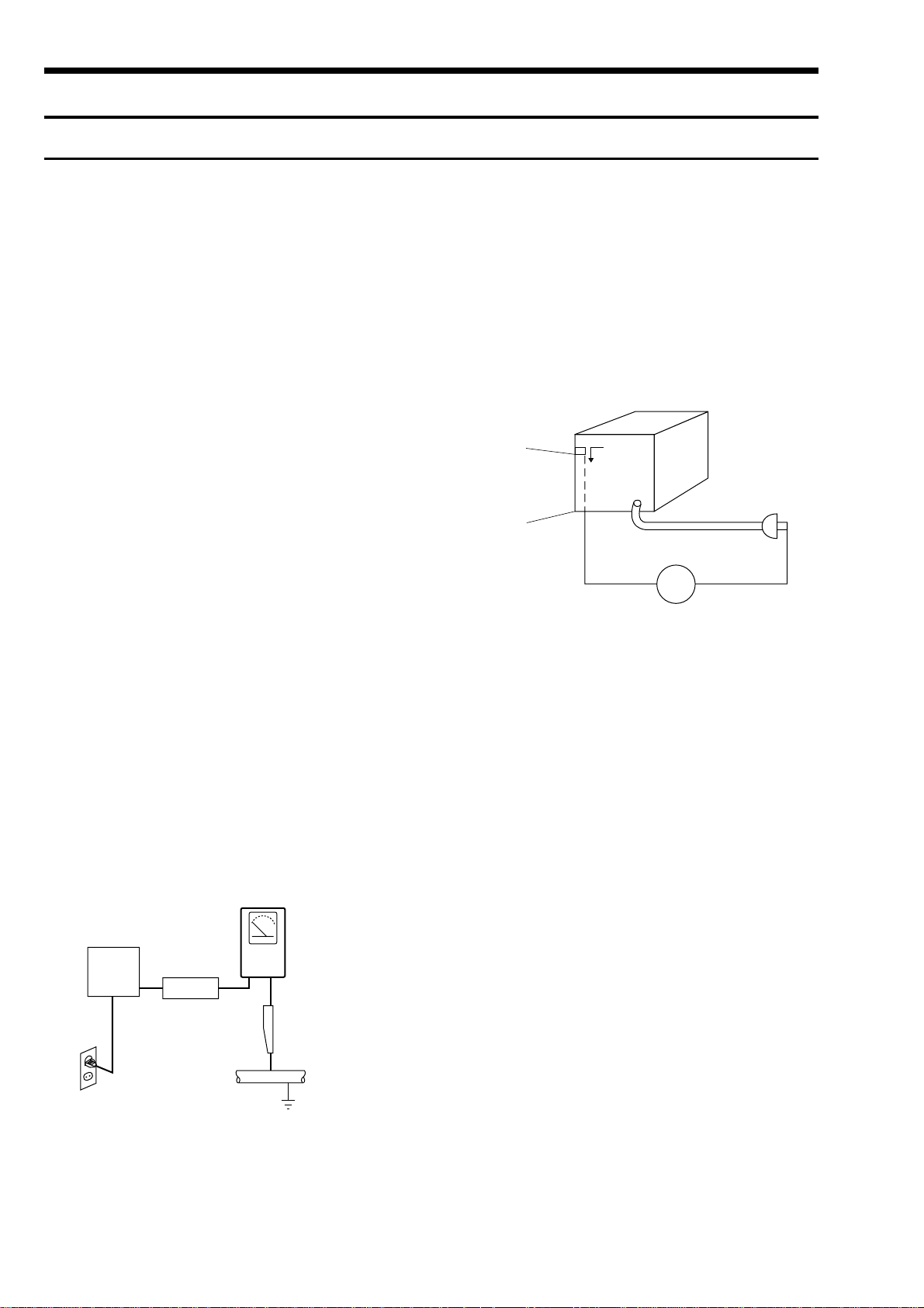
(3) Leakage Current Hot Check-With the instrument completely
reassembled, plug the AC line cord directly into a 120V AC
outlet. (Do not use an isolation transformer during this test.)
Use a leakage current tester or a metering system that complies
with American National Standards institute (ANSI) C101.1
Leakage Current for Appliances and Underwriters Laboratories
(UL) 1270 (40.7). With the instrument’s AC switch first in the
ON position and then in the OFF position, measure from a known
earth ground (metal water pipe, conduit, etc.) to all exposed
metal parts of the instrument (antennas, handle brackets, metal
cabinets, screwheads, metallic overlays, control shafts, etc.),
especially any exposed metal parts that offer an electrical return
path to the chassis.
Any current measured must not exceed 0.5mA. Reverse the
instrument power cord plug in the outlet and repeat the test. See
Fig. 1.
Any measurements not within the limits specified herein indicate
a potential shock hazard that must be eliminated before returning
the instrument to the customer.
(READING SHOULD
NOT BE ABOVE
0.5mA)
EARTH
GROUND
DEVICE
UNDER
TEST
TEST ALL
EXPOSED METER
SURFACES
2-WIRE CORD
ALSO TEST WITH
PLUG REVERSED
(USING AC ADAPTER
PLUG AS REQUIRED)
LEAKAGE
CURRENT
TESTER
(4) Insulation Resistance Test Cold Check-(1) Unplug the power
supply cord and connect a jumper wire between the two prongs
of the plug. (2) Turn on the po wer switc h of the instrument. (3)
Measure the resistance with an ohmmeter between the jumpered
AC plug and all exposed metallic cabinet parts on the instrument,
such as screwheads, antenna, control shafts, handle brackets,
etc. When an exposed metallic part has a return path to the
chassis, the reading should be between 1 and 5.2 megohm. When
there is no return path to the chassis, the reading must be infinite.
If the reading is not within the limits specified, there is the
possibility of a shock hazard, and the instrument must be repared
and rechecked before it is returned to the customer. See Fig. 2.
Antenna
Terminal
Exposed
Metal Part
ohm
ohmmeter
Fig. 2 Insulation Resistance Test
2) Read and comply with all caution and safety related notes on or
inside the cabinet, or on the chassis.
3) Design Alteration W arning-Do not alter or add to the mechanical
or electrical design of this instrument. Design alterations and
additions, including but not limited to, circuit modifications and
the addition of items such as auxiliary audio output connections,
might alter the safety characteristics of this instrument and create
a hazard to the user. Any design alterations or additions will
make you, the servicer, responsible for personal injury or
property damage resulting therefrom.
4) Observe original lead dress. Take extra care to assure correct
lead dress in the following areas:
(1) near sharp edges, (2) near thermally hot parts (be sure that
leads and components do not touch thermally hot parts), (3) the
AC supply, (4) high voltage, and (5) antenna wiring. Always
inspect in all areas for pinched, out-of-place, or frayed wiring,
Do not change spacing between a component and the printedcircuit board. Check the AC power cord for damage.
5) Components, parts, and/or wiring that appear to have ov erheated
or that are otherwise damaged should be replaced with
components, parts and/ or wiring that meet original
specifications.
Additionally, determine the cause of ov erheating and/or damage
and, if necessary, tak e correctiv e action to remove any potential
safety hazard.
Fig. 1 AC Leakage Test
— 4 —

6) Product Safety Notice-Some electrical and mechanical parts
have special safety-related characteristics which are often not
evident from visual inspection, nor can the protection they gi ve
necessarily be obtained by replacing them with components rated
for higher voltage, wattage, etc. Parts that have special safety
characteristics are identified by shading, an ( ) or a ( ) on
schematics and parts lists. Use of a substitute replacement that
does not have the same safety characteristics as the
recommended replacement part might create shock, fire and/or
other hazards. Product safety is under review continuously and
new instructions are issued whenever appropriate.
— 5 —

2 SERVICING PRECAUTIONS
CAUTION: Before servicing units co vered by this service manual
and its supplements, read and follow the Safety Precautions section
of this manual.
Note: If unforseen circumstances create conflict between the
following servicing precautions and any of the safety precautions,
always follow the safety precautions. Remember: Safety First.
2-1 General Servicing Precautions
(1) a. Always unplug the instrument’s A C po wer cord from the AC
power source before (1) re-moving or reinstalling any
component, circuit board, module or any other instrument
assembly, (2) disconnecting an y instrument electrical plug or
other electrical connection, (3) connecting a test substitute in
parallel with an electrolytic capacitor in the instrument.
b. Do not defeat any plug/socket B+ voltage interlocks with
which instruments covered by this service manual might be
equipped.
c. Do not apply AC power to this instrument and/or any of its
electrical assemblies unless all solid-state device heat sinks
are correctly installed.
d. Always connect a test instrument’s ground lead to the
instrument chassis ground before connecting the test
instrument positive lead. Always remove the test instrument
ground lead last.
Note: Refer to the Safety Precautions section ground lead last.
(2) The service precautions are indicated or printed on the cabinet,
chassis or components. When servicing, follow the printed or
indicated service precautions and service materials.
(3)The components used in the unit have a specified flame
resistance and dielectric strength.
When replacing components, use components which have the
same ratings. Components identified by shading, by ( ) or by
( ) in the circuit diagram are important for safety or for the
characteristics of the unit. Always replace them with the exact
replacement components.
(4) An insulation tube or tape is sometimes used and some
components are raised above the printed wiring board for safety .
The internal wiring is sometimes clamped to prevent contact
with heating components. Install such elements as they were.
(5) After servicing, always check that the removed screws,
components, and wiring have been installed correctly and that
the portion around the serviced part has not been damaged and
so on. Further, check the insulation between the blades of the
attachment plug and accessible conductive parts.
2-2 Insulation Checking Procedure
Disconnect the attachment plug from the AC outlet and turn the
power ON. Connect the insulation resistance meter (500V) to the
blades of the attachment plug. The insulation resistance between
each blade of the attachment plug and accessible conductive parts
(see note) should be more than 1 Megohm.
Note: Accessible conductive parts include metal panels, input
terminals, earphone jacks, etc.
— 6 —

3 ESD PRECAUSIONS
Electrostatically Sensitive Devices (ESD)
Some semiconductor (solid state) devices can be damaged easily
by static electricity.
Such components commonly are called Electrostatically Sensitive
Devices (ESD). Examples of typical ESD devices are integrated
circuits and some field-effect transistors and semiconductor chip
components. The following techniques should be used to help reduce
the incidence of component damage caused by static electricity.
(1) Immediately before handling any semiconductor component or
semiconductor-equipped assembly, drain off any electrostatic
charge on your body by touching a known earth ground.
Alternatively, obtain and wear a commercially available
discharging wrist strap device, which should be removed for
potential shock reasons prior to applying power to the unit under
test.
(2) After removing an electrical assembly equipped with ESD
devices, place the assembly on a conductive surface such as
aluminum foil, to prevent electrostatic charge buildup or
exposure of the assembly.
(3) Use only a grounded-tip soldering iron to solder or unsolder
ESD devices.
(4) Use only an anti-static solder removal devices. Some solder
removal devices not classified as “anti-static” can generate
electrical charges sufficient to damage ESD devices.
(5) Do not use freon-propelled chemicals. These can generate
electrical charges sufficient to damage ESD devices.
(6) Do not remove a replacement ESD device from its protective
package until immediately before your are ready to install it.
(Most replacement ESD devices are packaged with leads
electrically shorted together by conductive foam, aluminum foil
or comparable conductive materials).
(7) Immediately before removing the protective materials from the
leads of a replacement ESD device, touch the protective material
to the chassis or circuit assembly into which the device will be
installed.
CAUTION: Be sure no power is applied to the chassis or circuit,
and observe all other safety precautions.
(8) Minimize bodily motions when handling unpackaged
replacement ESD devices. (Otherwise harmless motion such as
the brushing together of your clothes fabric or the lifting of
your foot from a carpeted floor can generate static electricity
sufficient to damage an ESD device).
— 7 —
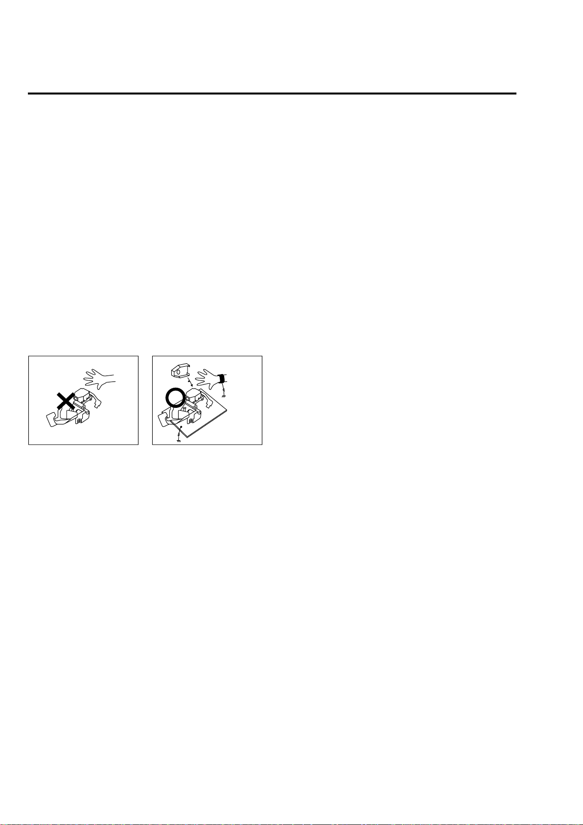
4 HANDLING THE OPTICAL PICK-UP
The laser diode in the optical pick up may suffer electrostatic
breakdown because of potential static electricity from clothing and
your body.
The following method is recommended.
(1) Place a conductive sheet on the work bench (The black sheet
used for wrapping repair parts.)
(2) Place the set on the conductive sheet so that the chassis is
grounded to the sheet.
(3) Place your hands on the conductive sheet (This gives them the
same ground as the sheet.)
(4) Remove the optical pick up block
(5) Perform work on top of the conductive sheet. Be careful not to
let your clothes or any other static sources to touch the unit.
◆ Be sure to put on a wrist strap grounded to the sheet.
◆ Be sure to lay a conductive sheet made of copper etc. Which is
grounded to the table.
WRIST-STRAP
FOR GROUNDING
1M
THE UNIT
1M
CONDUCTIVE SHEET
Fig.3
(6) Short the short terminal on the PCB, which is inside the Pick-
Up ASS’Y, before replacing the Pick-Up. (The short terminal is
shorted when the Pick-Up Ass’y is being lifted or moved.)
(7) After replacing the Pick-up, open the short terminal on the PCB.
— 8 —
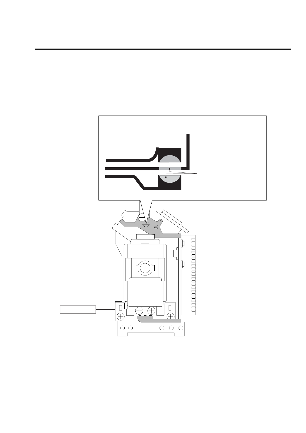
5 PICK-UP DISASSEMBLY AND REASSEMBLY
5-1 Disassembly
1) Remove the power cord.
2) Disassemble the Deck-Assy.
3) Make solder land 2 points short on Pick-up.
(See Fig. 4)
4) Disassembly the Pick-up.
Note: If the assembly and disassembly are not done in correct sequence, the Pick-up may be damaged.
5-2 Assembly
1) Replace the Pick-up.
2) Remove the soldering 2 points on Pick-up.
3) Reassemble the Deck-Assy.
SOLDER LAND 2 POINTS SHORT
PICK-UP ASS'Y
Fig. 4
— 9 —

MEMO
— 10 —
SLV-D360P/D560P
1. GENERAL
About this manual
Check your model name
The instructions in this manual are for the 2
SLV-D560P
models:
your model name by looking at the rear
panel of your
SLV-D560P
purposes. Any difference in operation is
clearly indicated in the text, for example,
SLV-D560P
“
•
This manual mainly explains operations
using the remote, but the same operations can
also be performed using the buttons on the
DVD-VCR having the same or similar
names.
•“DVD” may be used as a general term for DVD
VIDEOs, DVD-RWs/DVD-Rs, and DVD+RWs/
DVD+Rs.
•The meaning of the icons used in this manual is
described below:
Icon Meaning
*MP3 (MPEG 1 Audio Layer 3) is a standard format
defined by ISO/MPEG which compresses audio
data.
6
About this manual
and
DVD-VCR
is the model used for ill ustration
only”.
Functions available for DVD
VIDEOs and DVD-RWs/DVDRs in video mode or DVD+RWs/
DVD+Rs
Functions available for DVDRWs in VR (Video Recording)
mode
Functions available for VIDEO
CDs, Super VCDs or CD-Rs/CDRWs in video CD format or Super
VCD format
Functions available for music
CDs or CD-Rs/CD-RWs in music
CD format
Functions available for DATA
CDs (CD-ROMs/CD-Rs/CDRWs containing MP3
tracks or JPEG files)
Functions available for DATA
DVDs (DVD-ROMs/DVD+RWs/
DVD+Rs/DVD-RWs/DVD-Rs
containing MP3
JPEG files)
Functions available for VHS
VIDEOs
SLV-D360P
.
*
audio tracks or
*
audio
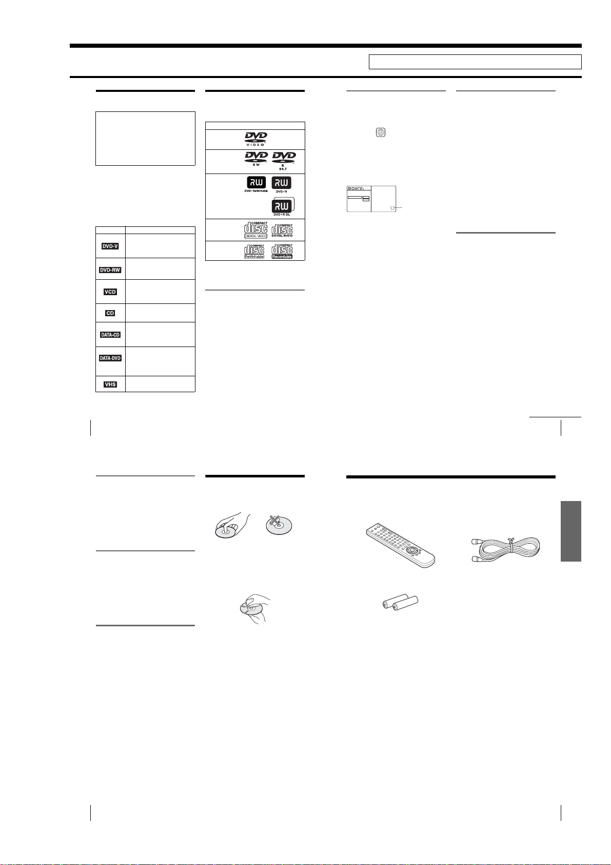
This player can play the
following discs
. Check
Format of discs
DVD VIDEO
DVD-RW/-R
DVD+RW/+R
VIDEO CD/
Music CD
CD-RW/-R
“DVD+RW,” “DVD-RW,” “DVD+R,” “DVD+R
DL,” “DVD-R,” “DVD VIDEO,” and “CD” logos
are trademarks.
Note about CDs/DVDs
The player can play CD-ROMs/CD-Rs/CD-RWs
recorded in the following formats:
–music CD format
–video CD format
–MP3 audio tracks and JPEG image fil es of
format conforming to ISO 9660* Level 1/
Level 2, or its extended format, Joliet
–KODAK Picture CD format
*A logical format of files and folders on CD-ROMs,
defined by ISO (International Organization for
Standardization).
The player can play DVD-ROMs/DVD+RWs/
DVD+Rs/DVD-RWs/DVD-Rs recorded in the
following formats:
–MP3 audio tracks and JPEG image fil es of
format conforming to UDF (Universal Disk
Format).
This section is extracted from instruction manual. (2-584-679-11)
Region code
Your player has a region code printed on the back
of the unit and only will play DVD VIDEO discs
(playback only) labeled with identical region codes.
This system is used to protect copyrights.
DVDs labeled will also play on this player.
If you try to play any other DVD VIDEO, the
message “Playback prohibited by area limitations.”
will appear on the TV screen. Depending on the
DVD VIDEO, no region code indication may be
labeled even though playing the DVD VIDEO is
prohibited by area restrictions.
ALL
SLV-DXXXX
NO.
X
Region code
Example of discs that the player
cannot play
The player cannot play the following discs:
•CD-ROMs/CD-Rs/CD-RWs other than those
recorded in the formats listed on the previous
page.
•CD-ROMs recorded in PHOTO CD format.
•Data part of CD-Extras
• DVD Audios
• HD layer on Super Audio CDs
Also, the player cannot play the following discs:
•A DVD VIDEO with a different region code.
•A disc recorded in a color system other than
NTSC, such as PAL or SECAM (this player
conforms to the NTSC color system).
•A disc that has a non-standard shape (e.g.,
card, heart).
•A disc with paper or stickers on it.
•A disc that has the adhesive of ce lloph ane tape
or a sticker still left on it.
Notes about DVD+RWs/DVD+Rs,
DVD-RWs/DVD-Rs or CD-Rs/CDRWs
Some DVD+RWs/DVD+Rs, DVD-RWs/DVDRs or CD-Rs/CD-RWs cannot be played on this
player due to the recording quality or physical
condition of the disc, or the cha racteristic s of the
recording device and authoring software.
The disc will not play if it has not been co rrectly
finalized. For more information, refer to the
operating instructions for the recording device.
Note that some playback functions may not
work with some DVD+RWs/DVD+Rs, even if
they have been correctly finalized. In this case,
view the disc by normal playback. Also some
DATA CDs/DATA DVDs created in Packet
Write format cannot be played.
This player can play the following discs
continued
7
Note on playback operations of
DVDs and VIDEO CDs
Some playback operations of DVDs and VIDEO
CDs may be intentionally set by software
producers. Since this player plays DVDs and
VIDEO CDs according to the disc contents the
software producers designed, some playback
features may not be available. Also, refer to the
instructions supplied with the DVDs or VIDEO
CDs.
Music discs encoded with
copyright protection technologies
This product is designed to playback discs that
conform to the Compact Disc (CD) standard.
Recently, various music discs encoded with
copyright protection technologies are marke te d
by some record companies. Please be aware that
among those discs, there are some th at do not
conform to the CD standard and m ay not be
playable by this product.
Note on DualDiscs
This product is designed to playback discs that
conform to the Compact Disc (CD) standard. A
DualDisc is a two sided disc product which
mates DVD recorded material on one side with
digital audio material on the other side. Please
be aware that the audio side of a DualDisc may
not play on this product because these discs do
not conform to the CD standard.
“DualDisc” is a trademark of the Recording
Industry Association of America (RIAA).
Notes about discs
•To keep the disc clean, handle the disc by its
edge. Do not touch the surface.
•Do not expose the disc to direc t su nlight or
heat sources such as hot air ducts, or leave it in
a car parked in direct sunlight as the
temperature may rise considerably inside the
car.
•After playing, store the disc in it s case.
•Clean the disc with a cleaning cloth.
Wipe the disc from the center out.
Do not use solvents such as benzin e, thinner,
commercially available cleaners, or anti-static
spray intended for vinyl LPs.
Getting Started
Step 1 : Unpacking
Check that you have received the following items with the DVD-VCR:
•Remote commander • 75-ohm coaxial cable with F-type
•Size AA (R6) batteries
Note
•The supplied remote commander is for the exclu s ive use of this DVD-VCR.
connectors
Getting Started
8
Notes about discs
1-1
Unpacking
9
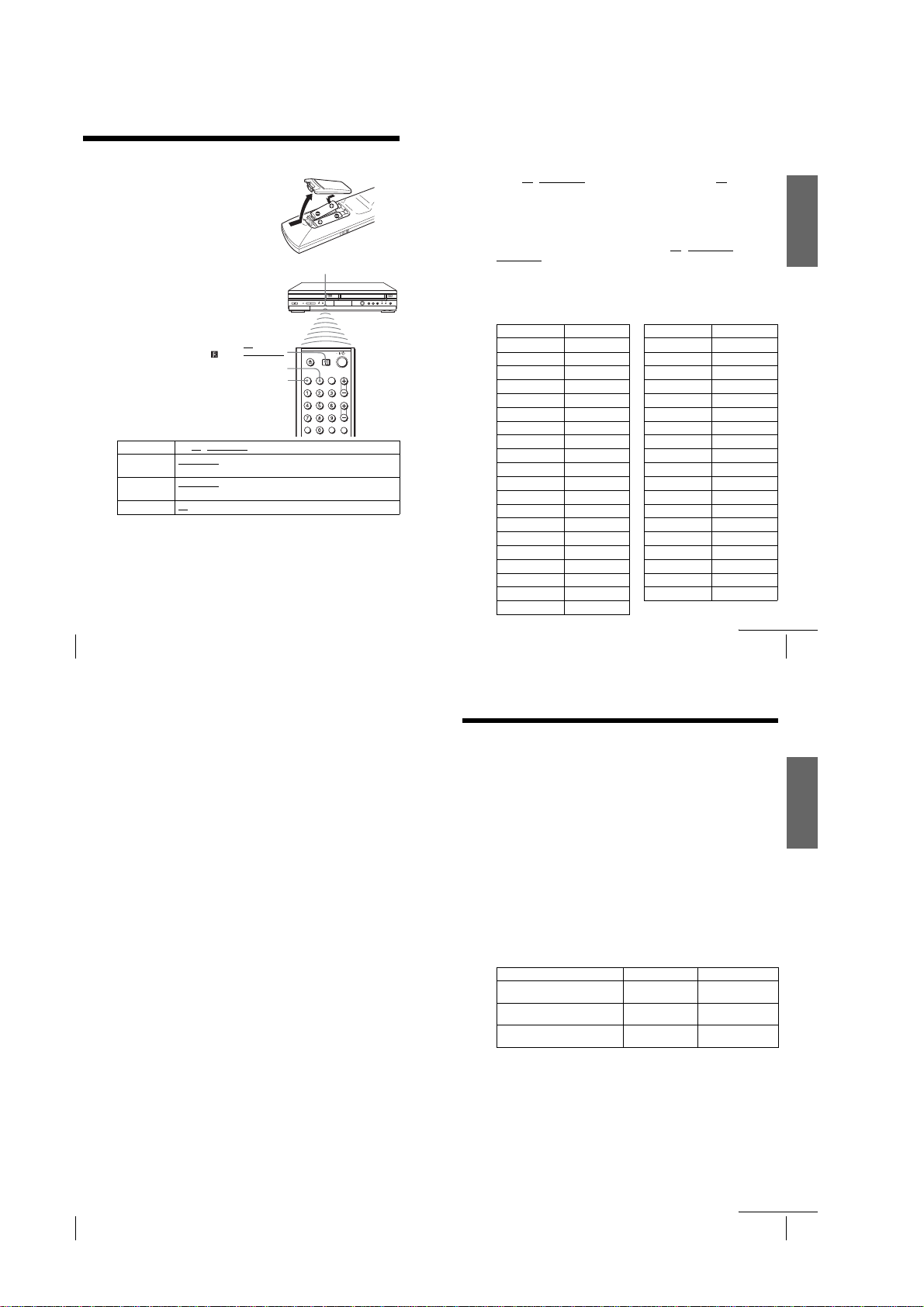
Step 2 : Setting up the remote commander
Inserting the batteries
Insert two size AA (R6) batteries by
matching the + and – on the batteries
to the diagram inside the battery
compartment.
Insert the negative (–) end first, then
push in and down until the positive
(+) end clicks into position.
SELECT
VIDEO
SELECT
DVD
Remote sensor
Using the remote
commander
You can use this remo te commander
to operate this DVD-VCR and a Sony
TV. Buttons on the remote
commander marked with an orange
dot (•) can be used to operate your
Sony TV.
If the TV does not have the
symbol near the remote sensor, this
remote commander will not operate
the TV .
To operate Set TV / DVD·VIDEO to
the DVD player DVD·VIDEO
the VCR DVD·VIDEO
your TV TV
Notes
•With normal use, the batteries should last about three to six months.
• If you do not use the remote commander for an extended period of time, remove the batteries
to avoid possible damage from battery leakage.
•Do not use a new battery with an old one.
•Do not use different types of batteries.
•Do not leave the remote commander in an extremely hot or humid place.
•Do not drop any foreign object into the remote casing, particularly when replacin g the batteries .
•Do not expose the remote sensor to direct light from the sun or lighting appa rat us. Doing so
may cause a malfunction.
10
Setting up the remote commander
TV /
DVD·VIDEO
, then press SELECT DVD and point at the remote sensor at
the DVD-VCR
, then press SELECT VIDEO and point at the remote sensor
at the DVD-VCR
and point at the remote sensor at your TV
Controlling other TVs with the remote commander
The remote commander is preprogrammed to control non-Sony TVs. If your TV is
listed in the following table, set the appropriate manufacturer’s code number.
Set TV / DVD·VIDEO at the top of the remote commander to TV.
1
Hold down ?/1, and enter your TV’s code number using the number buttons.
2
Then release ?/1.
Now you can use the ?/1, VOL +/–, CH +/–, MUTING*, TV/VIDEO and ENTER*
buttons to control your TV. You can also use the buttons marked with a dot (•) to
control a Sony TV. To control the DVD-VCR, reset TV
.
DVD·VIDEO
*for Sony TV only
Code numbers of controllable TVs
If more than one code number is listed, try entering them one at a time until you find
the one that works with your TV.
TV brand Code number
Sony 01
Akai 04
AOC 04
Centurion 12
Coronado 03
Curtis-Mathes 12
Daewoo 22
Daytron12
Emerson 03, 04, 14
Fisher 11
General Electric 06, 10
LG/Gold Star 03, 04, 17
Hitachi 02, 03
J.C.Penney 04, 12
JVC 09
KMC 03
Magnavox 03, 08, 12
Marantz 04, 13
MGA/Mitsubishi 04, 12, 13, 17
NEC 04, 12
/ DVD·VIDEO to
TV brand Code number
Panasonic 06, 19
Philco 03, 04
Philips 08
Pioneer 16
Portland 03
Quasar 06, 18
Radio Shack 05, 14
RCA 04, 10
Sampo 12
Sanyo 11
Scott 12
Sears 07, 10 , 11
Sharp 03, 05, 18
Sylvania 08, 12
Teknika03, 08, 14
Toshib a 07
Wards 0 3, 04, 12
Yorx 12
Zenith 15
continued
Setting up the remote commander
Getting Started
11
Notes
• If you enter a new code number, the code number previously entered will be erased.
• If the TV uses a different remote control system from the one programmed to work with the
DVD-VCR, you cannot control your TV with the remot e commander.
•When you replace the batteries of the remote commander, the code number may change. Set
the appropriate code number every time you replace the batteries.
12
Setting up the remote commander
Step 3 : Basic hookups
Before you get started
•Be sure to disconnect the AC power cord of each component before conn ecting.
•Turn off the power to all equipment.
•Do not connect the AC power cords until all of the connections are completed. If
you connect the A C po we r cord b efore the co nnect ions a re comp leted, you ma y not
be able to use the Plug and Play function.
•Be sure you make connections firmly. Loose connections may cause picture
distortion.
• If your TV does not match any of the examples provided, see your nearest Sony
dealer or qualified technician.
Selecting the best hookup option
There are many ways in which your DVD-VCR can be hooked up. To hook up your
DVD-VCR so that it works best for you, first scan th rou gh th e ta bl e be low. Then use
the accompanying diagrams and procedures on the following pages to set up your
DVD-VCR.
If your TV has audio/video inpu ts, refer to page 14 for audio/video (A/V) hookup.
Then follow one of the hookups below. If your TV does not have A/V inputs, go
directly to one of the hookups below.
If you have UseRefer to
Antenna only, no cable TV Hookup 1
No cable box or cable box with only a
few scrambled channels
Cable box with many scrambled
channels
After you have completed the connections, follow the instructions for setup.
After you have completed the setup, you are ready to use your DVD-VCR.
Procedures differ depending on the hookup you used.
Caution
Connections between the DVD-VCR’s VHF/UHF connector and the antenna terminals of the
TV receiver should be made only as shown in the following instructions. Failure to do so may
result in operation that violates the regulations of the Federal Communications Commission
regarding the use and operation of RF devices. Never connect the output of the DVD-VCR to an
antenna or make simultaneous (parallel) antenna and DVD-VCR connections at the antenna
terminals of your receiver.
Note to CATV system installer (in USA)
This reminder is provided t o call the CATV system installer’s attention to Ar ticle 820- 40 of the
NEC that provides guidelines for proper grounding and, in particul ar, specifies that the cab le
ground shall be connected to the grounding system of the building, as close to the point of cable
entry as practical.
(Plug and Play)
Hookup 2
(Plug and Play)
Hookup 3 Page 19
Pages 15 and 16
Pages 17 and 18
continued
Basic hookups
Getting Started
13
1-2
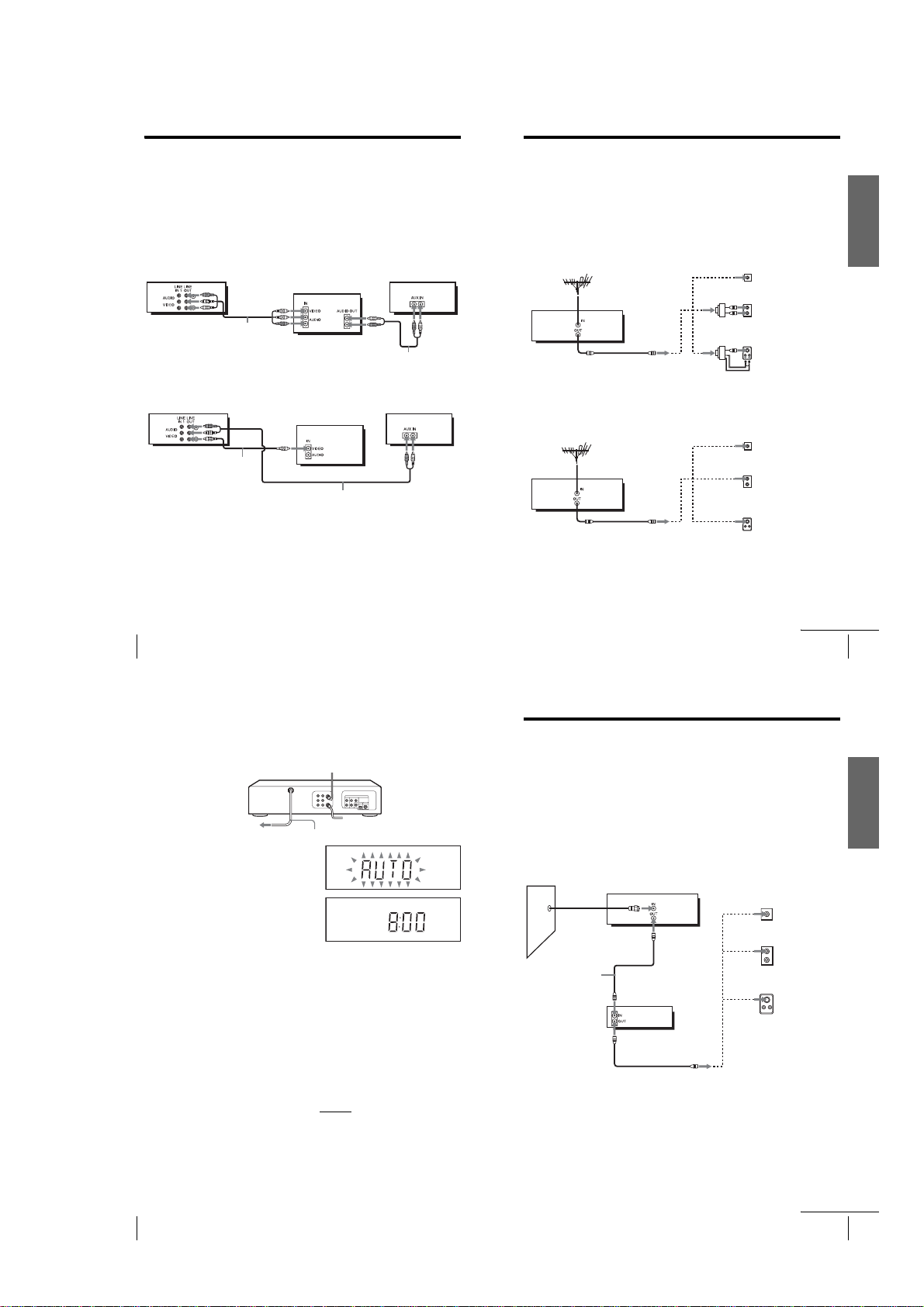
Audio/video (A/V) hookup
If your TV has audio/video (A/V) input jacks, you will get be tter pictu re and soun d if
you hook up your DVD-VCR using these connections. If your TV does not have A/V
inputs, see the following pages for antenna or cable hookups. Note that “Advanced
Hookups” (page 62) explains additional hookup methods that will optimize the
picture and sound for a true “hometheater” experience.
If you are not planning to use your DVD-VCR to record programs, you only need to
make the connections shown on this page. If you want to record regular or cable TV
programs, complete these connections first, and then go to the following pages for
antenna or cable hookups.
A Use this hookup if your TV has stereo jacks
Audio/video cord
(not supplied)
B Use this hookup if your TV does not have stereo jacks
Video cord
(not supplied)
Notes
•To play a tape/disc in stereo, you must use the A/V connection.
• If you do not have a stereo receiver, connect the white LINE OUT/AUDIO L jack to the
AUDIO IN jack on your TV.
14
Basic hookups
TV
Audio cord (not supplied)
TV
Audio c ord (not supplied)
Hookup 1 (Plug and Play)
Antenna hookup
Make the following connections if you are using an antenna (if you do not have cable
TV).
A Use this hookup if you are using:
• VHF/UHF antenna (you get channels 2–13 and channels 14 and higher)
• UHF-only antenna (you get channels 14 and higher)
•Separate VHF and UHF antennas
Rear of TV
Stereo receiverDVD-VCR
DVD-VCR
Stereo receiverDVD-VCR
B Use this hookup if you are using a VHF-only antenna (you get
channels 2–13 only)
DVD-VCR
If you cannot connect your antenna cable to the DVD-VCR directly
If your antenna cable is a flat cable (300-ohm twin lead cable), attach an external
antenna connector (not supplied) so you can connect the cable to the IN connector. If
you have separate cables for VHF and UHF antennas, you should use a U/V band
mixer (not supplied) (page 112).
VHF/UHF
Match the type of
A
VHF
UHF
VHF
UHF
Rear of TV
VHF/UHF
VHF
UHF
VHF
UHF
connector on your
TV: A, B, or C.
B
C
A
Match the type of
connector on your
TV: A, B, or C.
For connector
B
types B and C, no
UHF connection is
required.
C
continued
Basic hookups
or
or
or
or
Getting Started
15
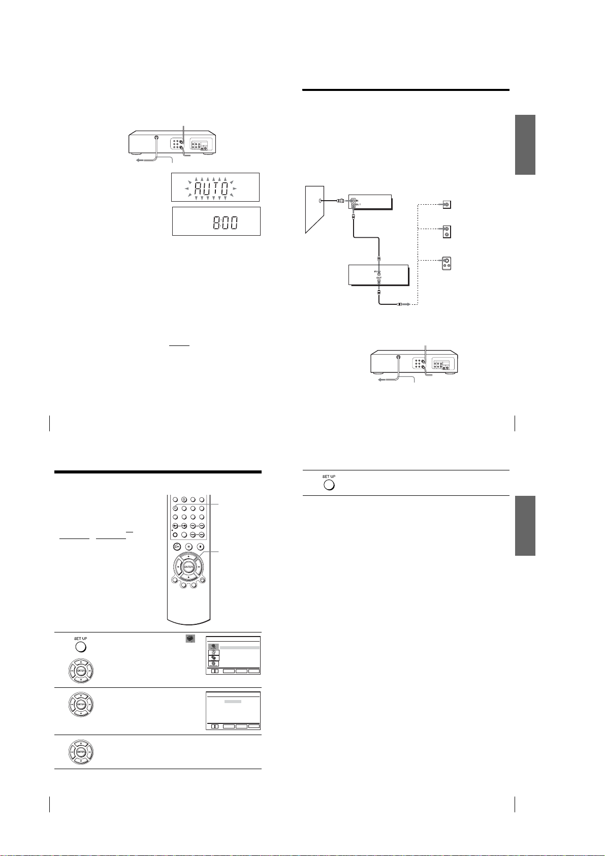
Hookup 1 : DVD-VCR setup
Plug the DVD-VCR into an AC outlet.
The DVD-VCR automatically presets the DVD-VCR’s clock and TV channels
when the DVD-VCR is plugged into the AC outlet.
to AC outlet
The DVD-VCR starts presetting the
clock and channels.
When Auto preset is completed, the
current time appears in the display
window.
You have now completed DVD-VCR setup.
To change the on-screen display langua g e to Fr e nch or Spanish, see
“Step 4 : Selecting a language” on page 20.
The clock is set using a time signal provided by some T V c hannels. If the clock
is incorrect, or “–:–” appears in the display window, see “Using Manual Clock
Set” on page 24.
To add or disable channels manually, see “Presetting/disabling channels
manually” on page 28.
Notes
• If you connect the AC power cord before the antenna connections are completed, the channels
may be incorrectly set. If this happens, see “Step 6 : Presetting channels” on page 26.
•Do not press any buttons on the DVD-VCR or remote commander during Auto preset.
•Auto preset starts automatically only when you plug in the AC power cord for the first time
after you purchase the DVD-VCR.
•Auto preset can be performed by pressing x on the unit
with the DVD-VCR power turned off.
AC power cord
continuously for 5 seconds or more
Hookup 2 (Plug and Play)
You have no cable box, or a cable box with only a few
scrambled channels
Recommended use
Use this hookup if you do not have a cable box. Also use this hookup if your cable
system scrambles only a few channels.
What you can do with this hookup
•Record any unscrambled channel by selecti ng the channel on the VCR
What you cannot do
•Record scrambled channels that require a cable box
Wall
Connect this cable
directly to your TV if
you do not have a
cable box.
DVD-VCR
Cable box
or
or
Rear of TV
VHF/UHF
VHF
UHF
VHF
UHF
A
Match the type
of connector
on your TV: A,
B, or C.
B
For connector
types B and C,
no UHF
connection is
required.
C
Getting Started
16
Basic hookups
1-3
continued
Basic hookups
17
Hookup 2 : DVD-VCR setup
Plug the DVD-VCR into an AC outlet.
The DVD-VCR automatically presets the DVD-VCR’s clock and TV channels
when the DVD-VCR is plugged into the AC outlet.
to AC outlet
The DVD-VCR starts presetting the
clock and channels.
When Auto preset is completed, the
current time appears in the display
window.
You have now completed DVD-VCR setup.
To change the on-screen display langua g e to Fr e nch or Spanish, see
“Step 4 : Selecting a language” on page 20.
The clock is set using a time signal provided by some T V c hannels. If the clock
is incorrect, or “–:–” appears in the display window, see “Using Manual Clock
Set” on page 24.
To add or disable channels manually, see “Presetting/disabling channels
manually” on page 28.
Notes
• If you connect the AC power cord before the antenna connections are completed, the channels
may be incorrectly set. If this happens, see “Step 6 : Presetting channels” on page 26.
•Do not press any buttons on the DVD-VCR or remote commander during Auto preset.
•Auto preset starts automatically only when you plug in the AC power cord for the first time
after you purchase the DVD-VCR.
•Auto preset can be performed by pressing x on the unit
with the DVD-VCR power turned off.
AC power cord
continuously for 5 seconds or more
Hookup 3
Connecting a cable box with many scrambled channels
Recommended use
Use this hookup if your cable system scrambles all or most channels.
What you can do with this hookup
•Record any channel by selecting the channel on the cable box
What you cannot do
•Recor d with the cable box turned off
•Record one channel while watching a nother channel
Wall
After you have completed hookup…
After you have completed hookup, plug the DVD-VCR into an AC outlet and see
“Step 4 : Selecting a language” on page 20.
Cable box
DVD-VCR
or
or
Rear of TV
VHF/UHF
VHF
UHF
VHF
UHF
A
Match the type of
connector on your
TV: A, B, or C.
B
For connector
types B and C, no
UHF connection
is required.
C
Getting Started
18
Basic hookups
Step 4 : Selecting a language
You can change the on-screen display
language.
Before you start…
•Turn on the DVD-VCR and your TV.
•To control the DVD-VCR, set TV
DVD·VIDEO
to DVD·VIDEO on the
remote (page 10).
•Set the “RF Output Channel” to “3CH” or
“4CH” in “OPTION SETUP” menu
(page 110). If your TV is connected to the
DVD-VCR using A/V connections, set the
TV to video input.
• If the DVD player is in play mode, you
cannot display the setup menu. Stop the
DVD playback.
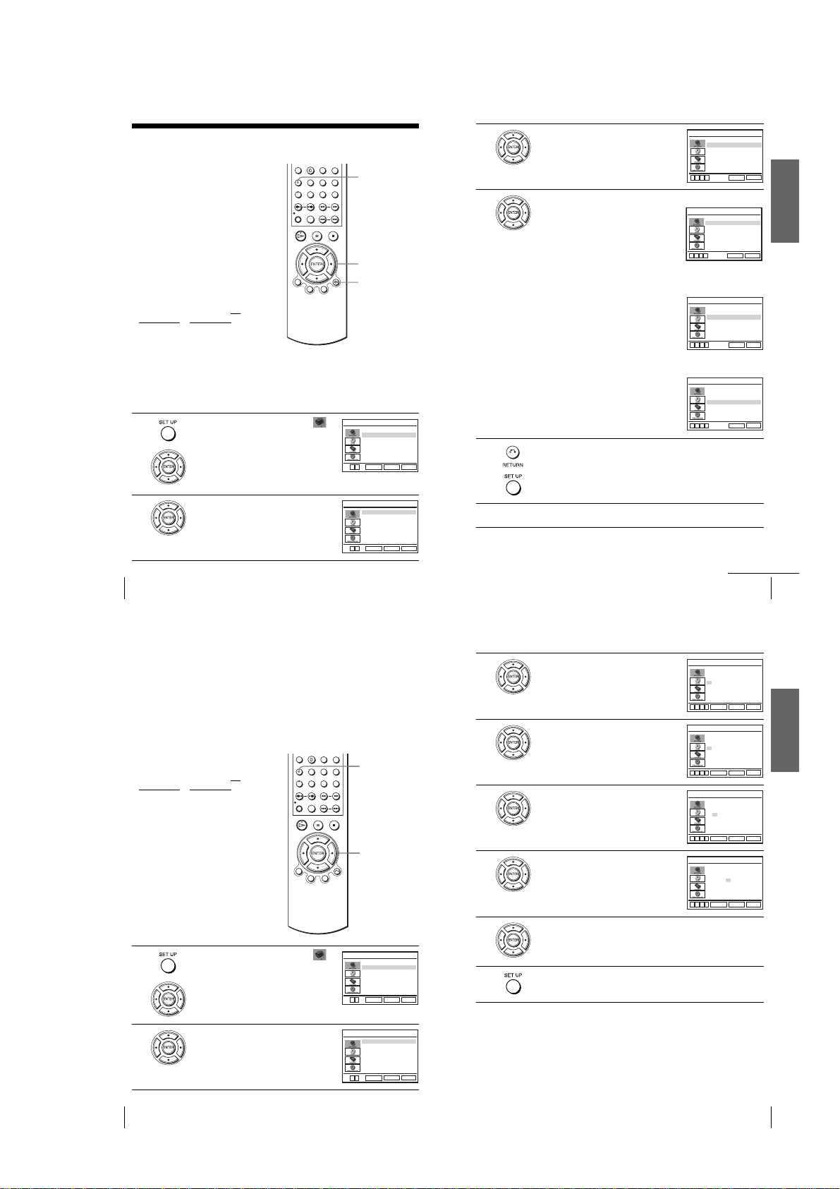
1
Press SET UP, then press V/v to select
(OPTION) and press ENTER.
/
SET UP
V/v
ENTER
Language
Clock Set/Adjust
Channel Setup
Auto Power Off
RF Output Channel
V
v
ENTER
OPTION SETUP
:English
[ Off ]
[3CH]
SET UP
RETURN
to AC outlet
4
Press SET UP to exit the menu.
AC power cord
Basic hookups
19
Getting Started
2
3
20
Selecting a language
Press V/v to select “Language”, then press
ENTER.
The “LANGUAGE/IDIOMA/LANGUE”
menu appears.
Press V/v to select the desired language, English, Spanish or French, then
press ENTER.
LANGUAGE/IDIOMA/LANGUE
B
English
Español
Français
V
v
RETURN
ENTER
SET UP
1-4
Selecting a language
21
Step 5 : Setting the clock
Using the Auto Clock Set
feature
Some TV and cable channels transmit time
signals with their broadcasts. Your DVDVCR can pick up this time signal to
automatically set the clock.
The Auto Clock Set feature works only if a
channel in your area is broadcasting a time
signal. If broadcasters in your area are not
yet sending time signals, set the time
manually (page 24 ) .
Before you start…
•Turn on the DVD-VCR and your TV.
When using a cable box, turn it on.
•To control the DVD-VCR, set TV
•Set the “RF Output Channel” to “3CH” or
• If the DVD player is in play mode, you
1
to DVD·VIDEO on the
DVD·VIDEO
remote (page 10).
“4CH” in “OPTION SETUP” menu
(page 110). If your TV is connected to the
DVD-VCR using A/V connections, set the
TV to video input.
cannot display the setup menu. Stop the
DVD playback.
Press SET UP, then press V/v to select
(OPTION) and press ENTER.
/
SET UP
V/v/B/b
ENTER
O RETURN
Language
Clock Set/Adjust
Channel Setup
Auto Power Off
RF Output Channel
V
v
ENTER
OPTION SETUP
:English
SET UP
RETURN
[ Off ]
[
3
4
3CH]
5
Press V/v to select “Auto”, then press
ENTER.
Press V/v to select the item you want, then press B/b to make the setting.
•For “Clock data CH”
Leave the setting to “Auto” to have the
DVD-VCR automatically search for a
channel that carries a time signal. Press
to select a channel that carries a t im e s ign al .
Use this option if you know of a channel that
carries a time signal. Most PBS member
stations broadcast a time signal. For the
fastest response, select your local PBS
station.
•For “Time zone”
Select the time zone of your area, or select
“Auto” to have the D VD-VCR automatic ally
set your time zone.
The options are:
Auto y Atl. (Atlantic) y East (Eastern)
y Cen. (Central) y Mtn.(Mountain) y
Pac. (Pacific) y Alas (Alaska) y
Haw.(Hawaii) y Auto
•For “Daylight saving”
Select “Yes” or “No” (standard time), or
“Auto” to have the D VD-VCR automatic ally
set the daylight saving time.
B/b
Press O RETURN, then press SET UP to exit the menu.
CLOCK SET/ADJUST
Clock data CH [ Auto ]
Time zone [ Auto ]
Daylight saving [ Auto ]
B
vVb
CLOCK SET/ADJUST
Clock data CH [ 123 ]
Time zone [ Auto ]
Daylight saving [ Auto ]
B
vVb
CLOCK SET/ADJUST
Clock data CH [ Auto ]
Time zone [ Pac. ]
Daylight saving [ Auto ]
B
vVb
CLOCK SET/ADJUST
Clock data CH [ Auto ]
Time zone [ Auto ]
Daylight saving [ No ]
B
vVb
RETURN
RETURN
RETURN
RETURN
SET UP
SET UP
SET UP
SET UP
Getting Started
2
Press V/v to select “Clock Set/Adjust”, then
press ENTER.
The “CLOCK SET/ADJUST” menu appears.
22
Setting the clock
Notes
•The clock cannot be set automatically if you do not receive a channe l that carries a time
signal in your area. If so, set the clock manually (page 24).
• If there are only a few channels in your area that carry time signals, setting the clock
automatically may take up to about 20 minutes. If nothing happens even after you wait about
20 minutes, set the clock manually (page 24).
• If you made Hookup 3, make sure you leave the cable box on.
•To record TV programs using the timer, you must set the clock accurately.
•The clock display appears when VIDEO mode is selected with no tape inserted or when the
DVD-VCR is turned off.
Using Manual Clock Set
Before you start…
•Turn on the DVD-VCR and your TV.
•To control the DVD-VCR, set TV
DVD·VIDEO
to DVD·VIDEO on the
remote (page 10).
•Set the “RF Output Channel” to “3CH” or
“4CH” in “OPTION SETUP” menu
(page 110). If your TV is connected to the
DVD-VCR using A/V connections, set the
TV to video input.
• If the DVD player is in play mode, you
cannot display the setup menu. Stop the
DVD playback.
V
v
CLOCK SET/ADJUST
Auto
Manual
ENTER
RETURN
6
SET UP
To activate the Auto Clock Set function, turn off the DVD-VCR.
continued
Setting the clock
3
4
Press V/v to select “Manual”, then press
ENTER.
Press V/v to set the hour.
SET UP
/
Press b to select the minutes and set the
minutes by pressing V/v.
Set the month, day, and year in sequence by
pressing b to select the item to be set, and
press V/v to select the digits, then press b.
V/v/B/b
ENTER
5
6
The day of the week is set automatically.
7
Press ENTER to confirm the setting.
vVb
vVb
vVb
vVb
B
B
B
B
CLOCK SET/ADJUST
Time Date
A
12:00
1/01 2005 Sat
M
ENTER
CLOCK SET/ADJUST
Time Date
A
12:00
1/01 2005 Sat
M
ENTER
CLOCK SET/ADJUST
Time Date
A
12:00
1/01 2005 Sat
M
ENTER
CLOCK SET/ADJUST
Time Date
A
12:00
10/06 2005 Thu
M
ENTER
RETURN
RETURN
RETURN
RETURN
23
Year
Getting Started
SET UP
Year
SET UP
Year
SET UP
Year
SET UP
1
2
24
Setting the clock
Press SET UP, then press V/v to select
(OPTION) and press ENTER.
Press V/v to select “Clock Set/Adjust”, then
press ENTER.
The “CLOCK SET/ADJUST” menu appears.
Language
Clock Set/Adjust
Channel Setup
Auto Power Off
RF Output Channel
V
v
Auto
Manual
V
v
OPTION SETUP
RETURN
ENTER
CLOCK SET/ADJUST
RETURN
ENTER
:English
SET UP
SET UP
[ Off ]
[
3CH]
8
Press SET UP to exit the menu.
Tip
•To change the digits while setting, press B to return to the item to be changed, and select the
digits by pressing V/v.
Notes
•To record TV programs using the timer, you must set the cl oc k ac cu ra tely.
•The clock display appears when VIDEO mode is selected with no tape inserted or when the
DVD-VCR is turned off.
Setting the clock
25
1-5
Step 6 : Presetting channels
This DVD-VCR is capable of receiving VHF
channels 2 to 13, UHF channels 14 to 69 and
unscrambled CATV channels 1 to 125. First,
we recommend that you preset the receivable
channels in your area using automatic
presetting methods. Then, if there are any
unwanted channels, disable them manually.
If you have already decided which channels
you wish to preset, set them directly using
manual presetting methods (page 28).
Presetting all receivable
channels automatically
Before you start…
•Turn on the DVD-VCR and your TV.
When using a cable box, turn it on.
•To control the DVD-VCR, set TV
DVD·VIDEO
to DVD·VIDEO on the
remote (page 10).
•Set the “RF Output Channel” to “3CH” or
“4CH” in “OPTION SETUP” menu
(page 110). If your TV is connected to the
DVD-VCR using A/V connections, set the
TV to video input.
• If the DVD player is in play mode, you
cannot display the setup menu. Stop the
DVD playback.
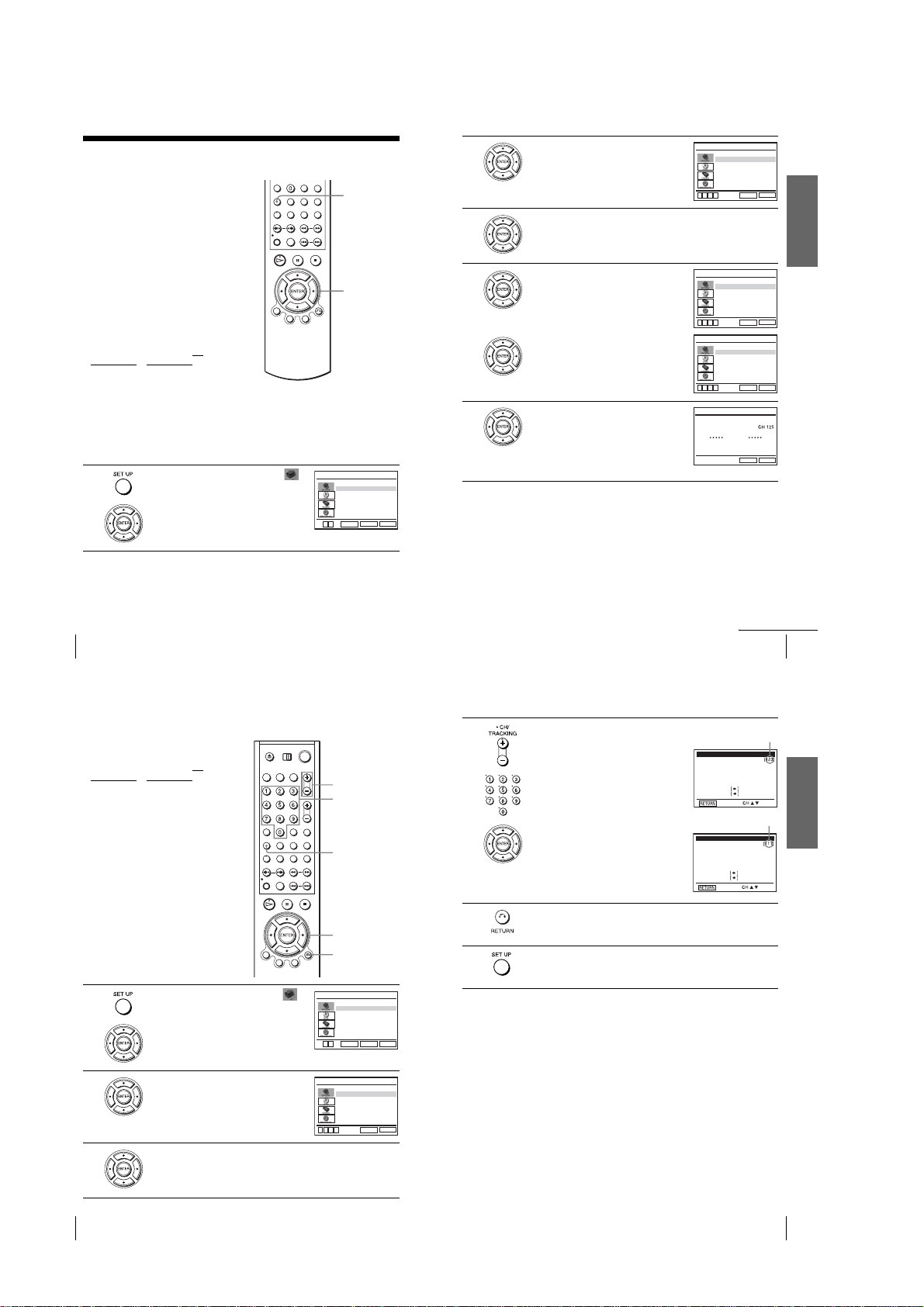
1
Press SET UP, then press V/v to select
(OPTION) and press ENTER.
/
Language
Clock Set/Adjust
Channel Setup
Auto Power Off
RF Output Channel
V
v
SET UP
V/v/B/b
ENTER
ENTER
OPTION SETUP
:English
[ Off ]
[3CH]
SET UP
RETURN
2
Press V/v to select “Channel Setup”, then
press ENTER.
The “CHANNEL SETUP” menu appears.
3
4
5
Press V/v to select “Ant/Cable.”
•To preset cable TV channels:
Press
B/b
to select “Cable TV.”
•To preset VHF and UHF channels:
B/b
to select “Antenna.”
Press
Press V/v to select “Auto Channel Memory,”
then press ENTER.
All receivable channels are preset in numerical
sequence. When no more receivable channels
can be found, presetting stops and the picture
from the lowest numbered channel is displayed
on the TV screen.
Ant/Cable [ C able TV ]
Auto Channel Memory
Channel Add/Delete
Guide Channel Setup
B
vVb
Ant/Cable [ C able TV ]
Auto Channel Memory
Channel Add/Delete
Guide Channel Setup
B
vVb
Ant/Cable [ Antenna ]
Auto Channel Memory
Channel Add/Delete
Guide Channel Setup
B
vVb
Memorizing
Please Wait
CHANNEL SETUP
SET UP
RETURN
CHANNEL SETUP
SET UP
RETURN
CHANNEL SETUP
SET UP
RETURN
AUTO CH MEMORY
SET UP
RETURN
Getting Started
26
Presetting channels
Presetting/disabling channels manually
Before you start…
•Turn on the DVD-VCR and your TV.
When using a cable box, turn it on.
•To control the DVD-VCR, set TV
DVD·VIDEO
to DVD·VIDEO on the
remote (page 10).
•Set the “RF Output Channel” to “3CH” or
“4CH” in “OPTION SETUP” menu
(page 110). If your TV is connected to the
DVD-VCR using A/V connections, set the
TV to video input.
• If the DVD player is in play mode, you
cannot display the setup menu. Stop the
DVD playback.
1
Press SET UP, then press V/v to select
(OPTION) and press ENTER.
/
CH +/–
Number
buttons
SET UP
V/v/B/b
ENTER
O RETURN
Language
Clock Set/Adjust
Channel Setup
Auto Power Off
RF Output Channel
V
v
ENTER
OPTION SETUP
:English
[ Off ]
[3CH]
SET UP
RETURN
4
5
6
To preset/disable a channel:
1
Press CH +/– or number buttons to enter
the channel number.
2
Press B/b to select “ADD” (in memory)
or “DELETE” (deleted).
3
Press ENTER.
Press O RETURN to confirm the setting.
Press SET UP to exit the menu.
Note
•If you have not preset channels automatically, you cannot preset/disable channels manually.
continued
Presetting channels
Channel to be preset
CHANNEL ADD/DELETE
Select channel:
(in memory)
to ADD
and press
to DELETE
press
Channel to be disabled
CHANNEL ADD/DELETE
Select channel:
(deleted)
to ADD
and press
to DELETE
press
27
Getting Started
2
3
28
Presetting channels
Press V/v to select “Channel Setu p”, then
press ENTER.
The “CHANNEL SETUP” menu appears.
Ant/Cable [ C a ble TV ]
Auto Channel Memory
Channel Add/Delete
Guide Channel Setup
B
vVb
Press V/v to select “Channel Add/De lete,” then press ENTER.
CHANNEL SETUP
SET UP
RETURN
1-6
Presetting channels
29
Step 7 : Setting up the VCR Plus+® system
SAMPLE
(SLV-D560P only)
How the VCR Plus+ system works
Whenever you want to record a TV program,
all you need to do is look up the “PlusCode”
number, a number assigned to each program
published in the TV section of most
newspapers, cable TV listings, and even TV
GUIDE magazine. Then, just enter the
PlusCode number of the program you want
and the VCR is automatically programmed to
record that show. It’s that simple.
How to set up your VCR
Setting up your VCR involves coordinating
the TV channel number (the number you turn
to on your TV or VCR to watch a program)
with the guide channel (the number that is
assigned to that channel in your program
guide).
To fi nd the guide channel numbers, look at
the “Channel Line-up Chart” in the program
guide for your area that features VCR
PlusCode numbers. It usually looks like the
example to the right.
To set the guide channels, use the Channel
Line-up Chart to check that the guide channel
numbers match the TV channel your VCR
receives. For example , if HBO is liste d in the
Channel Line-up Chart as channel 33, and
your VCR receives HBO on channel 5, you
need to coordinate these numbers using the
following procedure. If the guide and TV
channel numbers are the same, you can skip
this procedure.
Example of “PlusCode”
PlusCode
14
5:30
MOVIE Musical (2hrs.)
2
SPORT
CNN
WS 9974
4
23
6:30
DRAMA
5
SCIENCE AND TECHNOLOGY
(1hr. 15min.) 73457
33044
Golf (1hr. 25min.) 42060
Comedy (2hrs.) 17390
Example of “Channel Line-up Chart”
CABLE
CH
16
17
20
21
22
25
34
35
5
27
29
30
31
38
39
45
17
44
49
50
51
CABLE TV
AMC
American Movie Classics
BRV
Bravo (program grid only)
CNN
Cable News Network
CSP
C-SPAN
The Disney Channel
DIS
DSC
The Discovery Channel
ESN
ESPN
FAM
The Family Channel
Home Box Office
HBO
LIF
Lifetime
MAX
Cinemax
MTV
Music Television
Nickelodeon
NIK
SC
Sports Channel
SCA
Sports Channel America
SHO
Showtime
TBS
TBS SuperStation
TMC
The Movie Channel
TNN
The Nashville Network
TNT
Turner Network Television
USA
USA Network
VCR Plus+
GUIDE CH
35
54
42
28
53
37
34
47
33
46
45
48
38
59
70
41
43
58
49
52
44
SET UP
Getting Started
V/v/B/b
ENTER
O RETURN
1
2
Press SET UP, then press V/v to select
(OPTION) and press ENTER.
Press V/v to select “Channel Setup”, then
press ENTER.
The “CHANNEL SETUP” menu appears.
3
Press V/v to select “Guide Channel Setup,”
then press ENTER.
Language
Clock Set/Adjust
Channel Setup
Auto Power Off
RF Output Channel
V
v
ENTER
Ant/Cable [ C able TV ]
Auto Channel Memory
Channel Add/Delete
Guide Channel Setup
B
vVb
GUIDE CHANNEL SETUP
[GUIDE CH]
[TV CH]
Enter actual
receiving channel
B
vVb
OPTION SETUP
:English
SET UP
RETURN
CHANNEL SETUP
SET UP
RETURN
SET UP
RETURN
[ Off ]
[3CH]
30
Setting up the VCR Plus+® system (SLV-D560P only)
4
5
6
7
8
The upper row shows VCR Plus+ guide channels and the lower row shows
TV channels or cable box out put channels. Press B/b to select the channel
number that does not match the guide channel.
•If you made Hookup 1 (page 15) or 2 (page 17): Enter the actual number
on your TV (and VCR), then press V/v.
•If you made Hookup 3 (page 19): Enter the cabl e box output channel
(usually 2, 3, or 4), then press V/v.
Repeat steps 4 and 5 for each channel number that doe s not match.
Press O RETURN to confirm the setting.
Press SET UP to exit the menu.
continued
Setting up the VCR Plus+® system (SLV-D560P only)
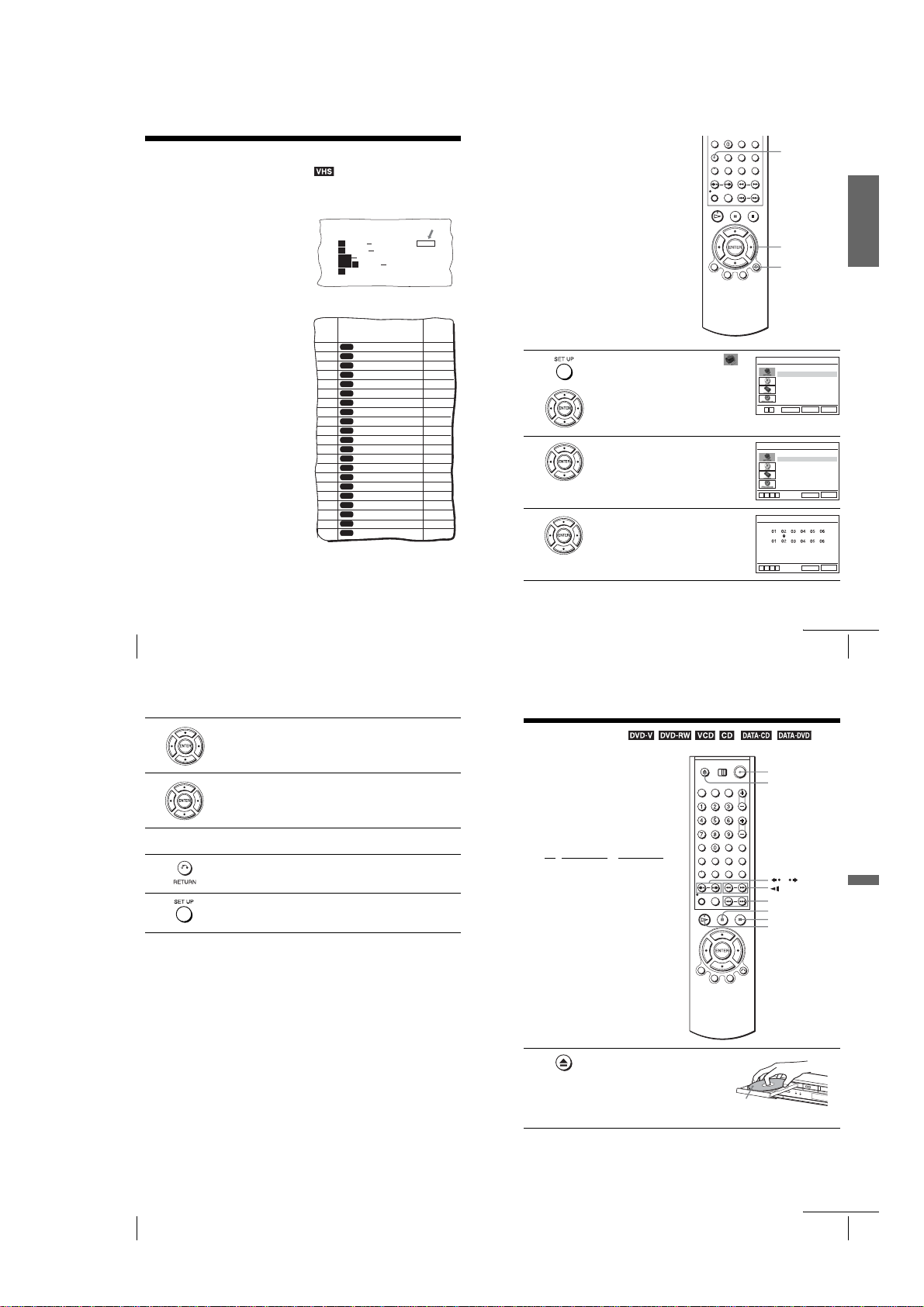
Basic Operations
Playing discs
Depending on the disc, some operations may
be different or restricted. Refer to the
operating instructions supplied with your
disc.
Before you start ...
•Turn on the DVD-VCR and your TV.
•Switch the input selector on your TV so
that the signal from the player appears on
the TV screen.
•Set TV
/ DVD·VIDEO to DVD·VIDEO,
then press SELECT DVD to control the
DVD player (page10).
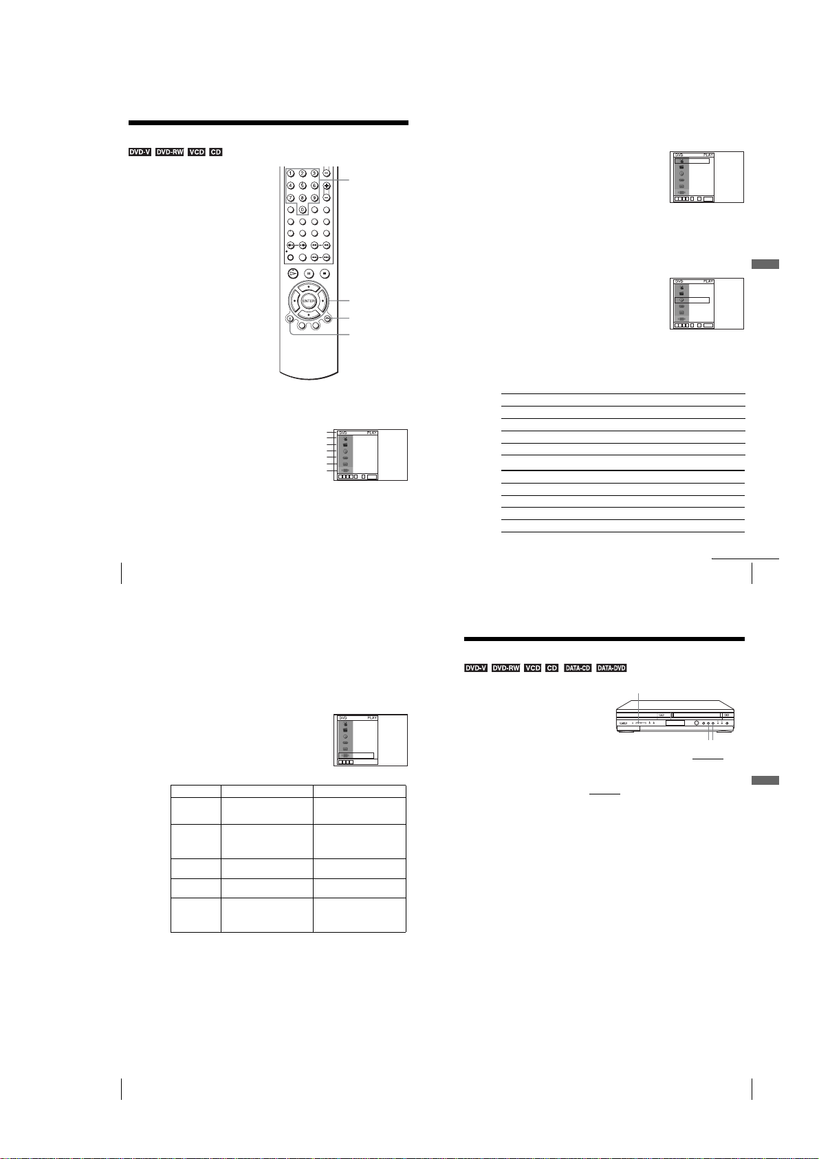
1
Press Z to open the disc tray and
place a disc on the disc tray.
?/1
Z
/
m/M y
./ >
X PAUSE
x STOP
H PLAY
31
Basic Operations
32
Setting up the VCR Plus+® system (SLV-D560P only)
1-7
with the playback
side facing down
continued
Playing discs
33
2
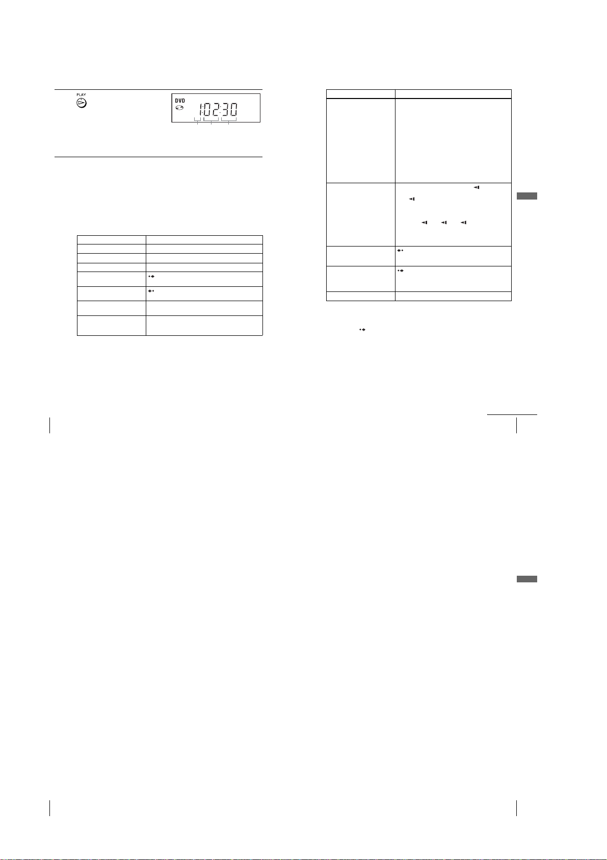
Press H PLAY.
The disc tray closes and the
DVD player starts playback.
The display window shows the
playback time
Depending on the disc, a menu
may appear on the TV screen.
For DVDs, see page 77. For VIDEO CDs, see page 99.
*“– – – – –” appears when no disc is loaded.
Tip
•To make a video timer reservation during DVD playback, we recommend performing the
operations under “Quick Timer Recording” (page 101).
Notes
•You c an change the screen type using the “SCREEN SETUP” menu (see “Screen Setup” on
page 68).
•Stop VIDEO playback while playing bac k a disc.
• If you play a DVD or VIDEO CD that has scratches, the player may stop playback at the
point of the scratch.
•Playback of play lists longer than 10 hours recorded in VR mode is not guaranteed.
*
.
Hour SecondMinute
Additional tasks
To Press
Stop play x STOP
1
Pause play*
Resume play after pause H PLAY
Go to the next frame in pause
mode
Go to the previous frame in
pause mode
Go to the next chapter, track, or
scene in continuous play mode
Go back to the previous chapter,
track, or scene in continuous
play mode
X PAUSE
SKIP
REPLAY
> NEXT on the remote or M on the unit
. PREV on the remote or m on the unit
To Press
Locate a point quickly
Watch slow motion in
continuous play mode
(DVD and VIDEO CD only)
Replay the previous scene for 10
seconds in continuous play
3
(Instant Replay)
mode*
Briefly fast forward the current
scene for 30 seconds in
continuous play mode*
(Instant Advance)
Stop play and remove the disc Z
*1If you pause the DVD player for more than 5 minutes, the DVD player will automatically stop.
2
Playback quickly or slowly with sound (See “To playback quickly or slowly with sound (DVD
*
only)” on page 36.)
*3For DVD VIDEOs and DVD-RWs/DVD-Rs or DVD+RWs/DVD+Rs only
4
*
You can press SKIP up to 4 times. This allows you to fast fow ard up to 2 minut es in tota l.
Tips
•The Instant Replay function is useful when you want to review a scene or dialog that you
missed.
•The Instant Advance function is useful when you want to pass over a scene that you do not
want to watch.
m
or M on the remote (or hold down m or
on the unit)
The playback speed changes as follows each time you
press the button on the remote (or depending on how long
you press the button on the unit):
•DVD
fast forward: PLAY t ×1.4 ••N•*
2M t 3M t 4M t 5M t 6M
fast reverse: PLAY t 1m t 2m t 3m t
4m t 5m t 6m
•CD, MP3 and VIDEO CD
fast forward: PLAY t 1M t 2M t 3M
fast reverse: PLAY t 1m t 2m t 3m
When you find the point you want, press H PLAY.
X PAUSE during playback, then press or y
The playback speed changes as follows each time you
press or y:
•DVD
forward slow motion: ×0.6
reverse slow motion (except for DVD-RW in VR
mode): 1 t 2 t 3
•VIDEO CD
forward slow motion only: 1 y t 2 y t 3 y
To resu me normal playback, press H PLAY.
REPLAY
SKIP
3*4
••N•*
2
t 1M t
2
t 2 y t 3 y
M
Basic Operations
34
Playing discs
Notes
•No sound is output except for:
–during normal play
–during playback quickly or slowly with sound
•You cannot perform playback quickly or slowly with sound when a virtual surround effect is
set.
•The fast reverse operation may not be possible for CD, MP3 and VIDEO CD dep en ding on
the recording method.
•You m ay not be able to use the Inst ant Replay or Instant Advance function with some scenes.
•Switching between original (ORG) and play li st (PL) within a disc recorded in VR mode is
possible only while the disc is stopped. Press TOP MENU to switch between ORG and PL.
To playback quickly or slowly with sound (DVD only)
You can listen to dialog or sound while playing the current scene quickly or slowly.
To playback quickly, press M during playback.
To playback slowly, press X PAUSE, th en press
H
PLAY to return to normal playback.
Press
Notes
•You c an not set virtual surround effects while performing playback quickly or slowly with
sound. In addition, you cannot perform playback quickly or slowly with sound when a
virtual surround effect is set.
•You c an not per form DT S audi o ou tpu t du rin g playback quickly or slowly with sound.
To Resume playback for the current disc (Resume Play)
The DVD player remembers the poin t wh e re yo u stopped the disc even if the DVD
player enters standby mode by pressing ?/1.
While playing a disc, press x STOP to stop playback.
1
Press H PLAY.
2
The DVD player starts pl ay ba c k fr om the poin t wh e r e yo u s top pe d the disc in
Step 1.
Tip
To begin playback from the top of the disc, press x
y
during playback.
STOP
twice then press H
PLAY
continued
Playing discs
Notes on playing DTS* sound tracks on a CD
•When playing DTS-encoded CDs, excessive noise will be heard from the analog ster eo ja cks .
To avoid possible damage to the audio system, the consumer should take proper precauti ons
when the analog stereo jack s o f t he DVD player are connected t o an ampli f icat ion sy ste m. To
enjoy DTS Digital Surround™ playback, an external 5.1-channel decoder system must be
connected to the digital jack of the DVD pla ye r.
•Set the sound to “Stereo” using the AUDIO button when you play DTS sound tracks on a CD
(page 87).
•Do not play DTS sound tracks without first connecting the DVD player to an audio
component having a built-in DTS decoder. The DVD player outputs the DTS signal via the
DIGITAL AUDIO OUT (CO AXIAL or OPTICAL) jack ev e n if “DTS” is set to “Off” in
“AUDIO SETUP” menu (page 66), and may affect your ears or cause your speakers to be
damaged.
Notes on playing DVDs with a DTS sound track
• DTS audio signals are output only through the DIGITAL AUDIO OUT (COAXIAL or
OPTICAL) jack.
•When you play a DVD with DTS sound tracks, set “DTS” to “On” in “AUDIO SETUP”
menu (page 66).
•If you connect the player to audio equipm ent without a DTS decoder, do not set “DTS” to
“On” in “AUDIO SETUP” menu (page 66). A loud noise may come out from the speake rs,
affecting your ears or causing the speakers to be damaged.
*“DTS” and “DTS Digital Out” are trademarks of Digital Theater Syste m s, Inc.
.
35
Basic Operations
36
Playing discs
1-8
Playing discs
37
Guide to the on-screen display
You can check disc information during
playback.
The displayed contents differ according to
the type of disc being played.
Press DISPLAY during playback. The following information appears; type of disc,
current title/track, chapter, counter position, voice language, subtitle language and
Custom A V Mo de sett ing. Refer t o “D VD Audio /Subtitle La nguage” on page126 for
the abbreviation of the language.
Current title/track number
Note
•You c an not selec t di sc in form a ti on i tem s when t he disc is stopped.
Type of disc
Current chapter number
Counter position
Voice language
Subtitle language
Custom AV Mode
Number buttons
V/v/B/b
ENTER
O RETURN
DISPLAY
1/3
1/36
T 0:01:09
ENG 5.1CH
ENG (3/5)
Standard
B
vVb
09
~
ENTER
To playback the desired titl e/track or chapter
You can playback the desired title/track or chapter using
this menu.
Press V/v during playback t o sele ct the desire d item .
1
Press B/b to change the item.
2
Press ENTER to start playback.
3
Press DISPLAY or O RETURN to turn off the
4
menu.
The title/track or chapter icon will appear on the DVD playback screen followed by
the current title/track or chapter number and the counter position.
To playback from the desired title/track counter position
You can playback from the desired title/track counter
position using this menu.
Press V/v during playback to select the counter
1
position icon.
Enter the desired elapsed playing time of the current
2
title/track using the number buttons.
Press ENTER to start playback.
3
Press DISPLAY or O RETURN to turn off the
4
menu.
Tip
•You can change the counter position information (pla ying time or remaining time) using
B/b
(DVD and CD only).
DVD
Indication Counter information
T ∗ :∗∗ : ∗∗ Elapsed playing time of the current title
T– ∗ : ∗∗ : ∗∗ Remaining time of the current title
C ∗ : ∗∗ : ∗∗ Elapsed playing time of the current chapter
C– ∗ : ∗∗ : ∗∗ Remaining time of the current chapter
CD
Indication Counter information
T ∗ :∗∗ : ∗∗ Elapsed playing time of the current track
T– ∗ : ∗∗ : ∗∗ Remaining time of the current track
D ∗ : ∗∗ :∗∗ Elapsed playing time of the disc
D– ∗ : ∗∗ : ∗∗ Remaining time of the disc
1/3
1/36
T 0:01:09
ENG 5.1CH
ENG (3/5)
Standard
B
vVb
09
~
ENTER
1/3
1/36
T 0:01:09
ENG 5.1CH
ENG (3/5)
Standard
B
vVb
09
~
ENTER
Basic Operations
38
Guide to the on-screen display
Notes
•The display may not change as operated depending on the disc.
•The display window continue indicating the playing tim e even when the counter position
information on the on-screen display is being changed.
To adjust the playback picture (Custom AV Mode)
You can adjust the video signal of the DVD or VIDEO CD (with PBC function off)
from the player to obtain the picture quality you want. Choose the setting that best
suits the program you are watching.
Press V/v during playback to select the Custom AV
1
Mode icon.
Press B/b to change the setting.
2
Setting Video Setting Audio Setting
Dynamic 1 Produces a bold dynamic picture
Dynamic 2Produces a more dynamic
Standard Off (Default setting)
Cinema 2 Enhances details in dark areas by
Cinema 1 White colors become brighter
Tip
•When you watch a movie, “Cinema 1” or “Cinema 2” is recommended.
by increasing the picture contrast
and the color intensity.
picture than Dynamic 1 by
further increasing the picture
contrast and the color intensity.
Displays a standard picture.
increasing the black level.
and black colors become richer,
and the color contrast is
increased.
1/3
1/36
T 0:01:09
ENG 5.1CH
ENG (3/5)
Standard
B
vVb
Full (modulated) sound with
clear treble and bass.
Full (modulated) sound with
even clearer treble and bass than
Dynamic 1.
Standard sound.
Powerful sound with even
stronger bass than Cinema 1.
Powerful sound with strong bass.
Guide to the on-screen display
Locking the disc tray
(Child Lock)
You can lock the disc tray so that the disc tray
is not opened by mistake.
To lock the disc tray
When the DVD-VCR is turned on, press x,X and SELECT DVD on the unit
same time. “LOCK” appears in the display window. The disc tray is locked.
To unlock the disc tray
Press x, X and SELECT DVD on the unit
unlocked.
Notes
•If you lock the disc tray while open, the disc tray will be locked after closing.
•You cannot lock the disc tray when the DVD-VCR is turned off. If the DVD-VCR is turned
on, you can lock the disc tray either in play mode or stop mode .
SELECT DVD
at the same time. The disc tray is
continued
39
xX
at the
Basic Operations
40
Guide to the on-screen display
1-9
Locking the disc tray (Child Lock)
41
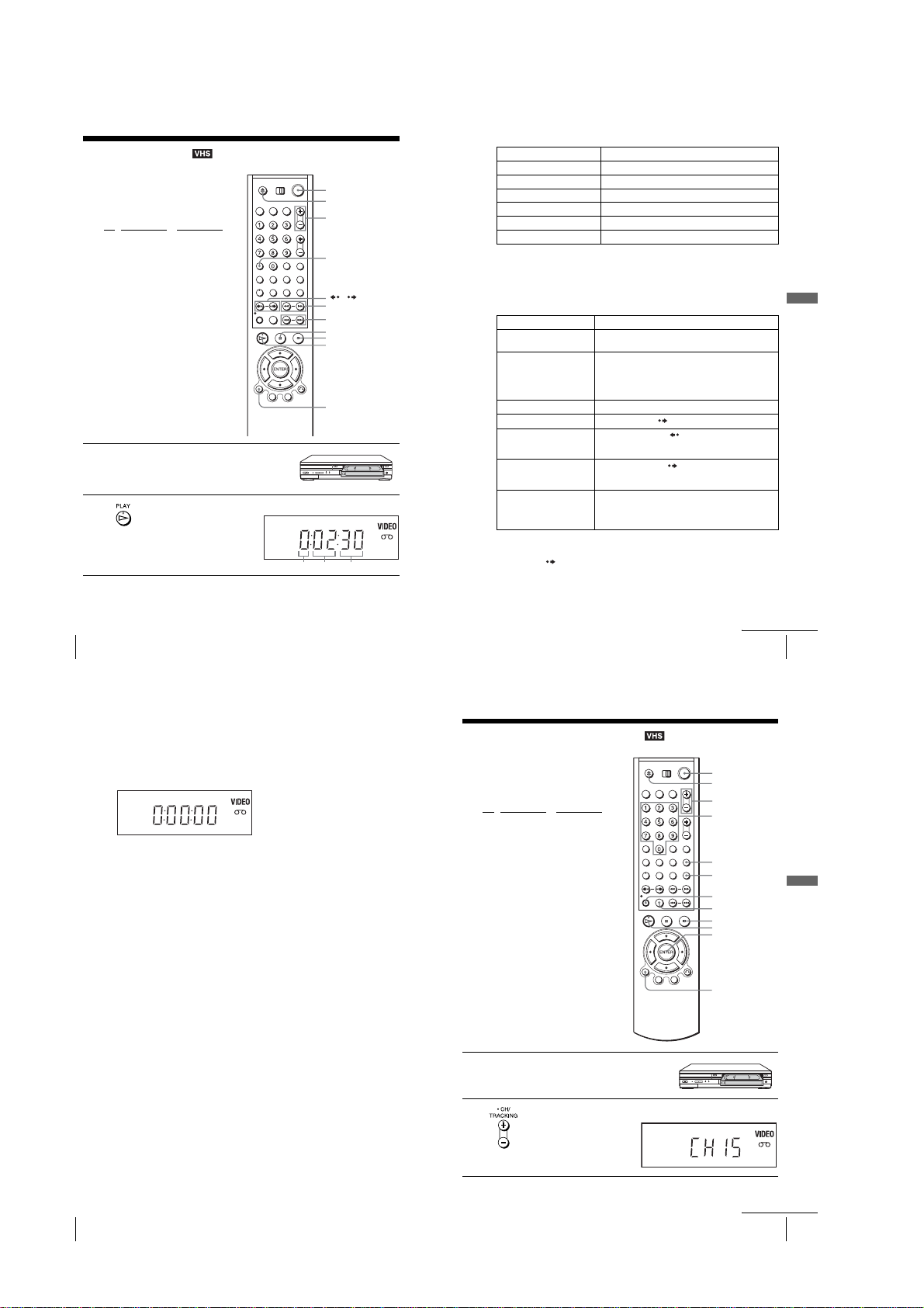
Playing a tape
Before you start ...
•Turn on the DVD-VCR and your TV.
•Switch the input selector on your TV so
that the signal from the player appears on
the TV screen.
•Set TV
/ DVD·VIDEO to DVD·VIDEO,
then press SELECT VIDEO to control the
VCR (page 10).
1
2
Insert a tape.
The VCR starts playing automatically if
you insert a tape with its safety tab
removed.
Press H PLAY.
The display window shows the
playback time.
When the tape reaches the end,
it will rewind automatically.
?/1
Z
TRACKING +/–
CLEAR
/
m/M y
./>
X PAUSE
x STOP
H PLAY
DISPLAY
Hour Minute Second
Additional tasks
To Press
Stop play x STOP
Pause play* X PAUSE
Resume play after pause X PAUS E or H PLAY
Fast-forward the tape M during stop
Rewind the tape m during st op
Eject the tape Z
* If you pause the VCR for more than 5 minutes, the VCR will automatically resume play.
To turn off the power while rewinding (Rewind Shut Off)
Press ?/1 while the tape is rewinding. The power will turn off but the tape will keep
rewinding until it reaches the end.
To play/search at various speeds
Playback options Operation
View t he pictur e during fastforward or rewind
Play at high speed • During playback, briefly press M or m. The tape
Play in slow motion*
Play frame by frame
Replay the previous scene in
continuous play mode*
(Instant Replay)
Fast forward the current scene
for 30 seconds in continuous
3
(Instant Skip)
play mode*
Play at various speeds
(Shuttle play)
*1You can change the slow motion playback speed by pressing M or m .
2
For 10 seconds in SP or LP mode/for 15 seconds in EP mode
*
*3You can press SKIP up to 4 times. This allows you to fast forward up to 2 m inutes in total.
During fast-forward, hold down M. During rewind, hold
down m.
continues to play at 5 times normal speed.
•During playback, hold down M or m. The tape
continues to play at 5 times normal speed. When you
release the button, normal playback resumes.
1
During pause, press y.
During pause, press SKIP.
During playback, press REPLAY.
2
During playback, press SKIP.
During playback, press .or >. You can change the
playback speed as follows.
–× 7y –×5 y –× 3 y STILL y SLOW y PLAY
y × 2 y ×3 y × 5y ×7
Basic Operations
42
Playing a tape
To resu me normal playback
Press H PLAY.
To use the time counter
Press CLEAR at the point on the tape that you want to find later. The counter in the
display window resets to “0:00:00.” To search for the counter 0:00:00 point
automatically, see “To search for the counter 0:00:00 point” on page 104.
To display the counter on the TV screen, press DISPLAY during normal playback.
Tip
•Adjust the picture using the TRACKING +/– buttons if:
–Streaks appear while playing in slow motion.
–Bands appear at the top or bottom while pausing.
–The picture shakes during pause.
Notes
•Tapes recorded in LP mode on other VCRs can be played back on this VCR but the picture
quality cannot be guaranteed.
•The counter resets to “0:00:00” whenever a tape is reinserted.
•The counter stops counting when it comes to a portion with no recording.
•When 10 hours have passed, the counter in the display wind ow retu rns to “ 0:00:00” and the
count starts over again.
•No sound is output during playback at various speeds.
•The picture may show noise when playing at high speed in reverse.
•While playing a tape, you can display the setup menu, but the remote commander’s function
switches to DVD automatically. Press O RETURN repeatedly to exit the menu.
•When playback does not start even if you insert a tape wit h its safety tab removed, set “Auto
Play” to “On” in the “VIDEO FUNCTION SETUP” menu (page 106).
•Stop disc playback while playing b ac k a video.
•The VCR can also play S-VHS tapes r eco rded by S-VHS mode. The VCR will automatically
identify the type of tape inserted in the VCR (either VHS or S-VHS). When S-VHS tapes are
played in the VCR, the enhanced reso lution will not be visible on screen; there may also be
picture distortion while playing the S-VHS tape in slow motion or wh ile utilizing other
special playback modes. The VCR will not record in S-VHS mode on an S-VHS tape.
•The playback of S-VHS tapes recorded in EP/LP mode cannot be guaranteed.
Recording TV programs
Before you start ...
•Turn on the DVD-VCR and your TV.
•Switch the input selector on your TV so
that the signal from the player appears on
the TV screen.
•Set TV
/ DVD·VIDEO to DVD·VIDEO,
then press SELECT VIDEO to control the
VCR (page 10).
•To record from a cable box, turn it on.
•Make sure the tape is longer than the total
recording time.
1
2
Insert a tape with its safety tab in place.
Press CH +/– to select the channel or line input video source you want to
record.
continued
Playing a tape
?/1
Z
CH +/–
Number buttons
TV/VIDEO
INPUT
SELECT
z REC
SP/EP
x STOP
H PLAY
ENTER
DISPLAY
43
Basic Operations
44
Playing a tape
1-10
continued
Recording TV programs
45
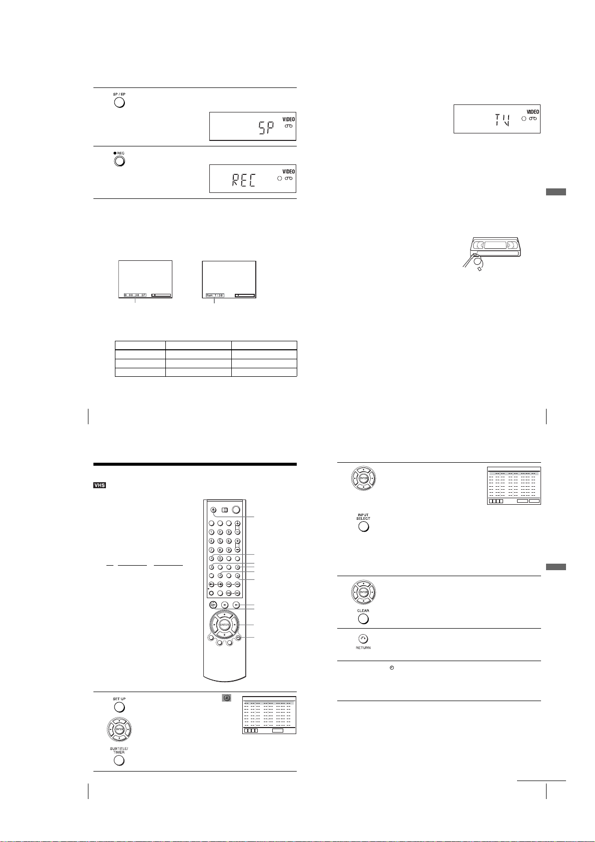
3
4
Press SP/EP to select the tape speed, SP or EP.
EP (Extended Play) provides recording time three times as long as SP
(Standard Play). However, SP produces better picture and audio quality.
Press z REC to start recording.
“
REC” appears in the display window.
To stop recording
Press x STOP.
To check the remaining tape length
Press DISPLAY to display the time counter. With the display on, press DISPLAY
again to check the remaining time. The white bar indicates the current location in
relation to the entire tape length. The remaining time also appears. Press DISPLAY
to turn off the indicators.
Time counter
To check the remaining tape length of a tape, set
FUNCTION SETUP
Maximum Recording Time
Tape Length SP EP
”
menu correctly (page 106).
T-120 2 hrs 6 hrs
T-160 2 hrs 40 mins 8 hrs
T-180 3 hrs 9 hrs
Remaining tape length
“
Tape Length” in the “VIDEO
To watch another TV program while recording
Press TV/VIDEO to display “TV” in the display window.
1
If your TV is connected to the VCR using A/V connections, set the TV to the
2
TV’s antenna input; if not, skip this step.
Select another channel on the TV.
3
To watch a DVD while recording
Press SELECT DVD to control the DVD player.
1
Press Z and place the disc on the disc tray.
2
Press H PLAY.
3
The disc tray closes and the DVD player starts playback. The TV screen will
automatically change to the DVD playback screen.
To save a recording
To prevent accidental erasure, break
off the safety tab as illustrated. To
record on the tape again, cover the tab
hole with adhesive tape.
Tips
•To select a channel, you can use the number buttons on the rem ote commander. Enter the
channel number, then press ENTER.
•You can select a video source from the LINE IN 1 or LINE-2 IN jacks using the INPUT
SELECT button.
•The display appears on the TV screen ind ic at ing information about the tape, but the
information will not be recorded on the tape.
•If you do not want to watch TV while recording, you can turn off the TV. When using a cable
box, make sure to leave it on.
Notes
•The remaining tape length may not be indicated accurately for short tapes such as T-20 or
T-30, or tapes recorded in LP mode.
•It may take up to one minute for the VCR to calculate and display the remaining tape length
after you press DISPLAY.
•You cannot record a DVD to a VCR tape.
•To watch a TV program during video recording, stop disc playback.
Safety tab
Basic Operations
46
Recording TV programs
Recording TV programs using the timer
You can preset up to eight programs at a
time.
Before you start…
•Check that the DVD-VCR clock is set to
the correct time.
•Turn on the DVD-VCR and your TV.
•Switch the input selector on your TV so
that the signal from the player appears on
the TV screen.
•Set TV
/ DVD·VIDEO to DVD·VIDEO,
then press SELECT VIDEO to control the
VCR (page 10).
•When using a cable box, turn it on.
•Insert a tape with its safety tab in place.
Make sure the tape is longer than the total
recording time.
• If the DVD player is in play mode, you
cannot display the setup menu. Stop the
DVD playback.
1
48
Recording TV programs using the timer
Press SET UP, then press V/v to select
(PROGRAM) and press ENTER. You can also
display the timer programmi ng menu by
pressing TIMER.
The timer programming menu appears.
CH START END DATE
B
vVb
Z
CLEAR
SET UP
TV/VIDEO
TIMER
INPUT
SELECT
x STOP
H PLAY
V/v/B/b
ENTER
O RETURN
RETURN
SPEED
2
3
4
5
Set the channel number, start and stop times,
date, and tape speed:
1
Press b to select each item in turn.
2
Press V/v to set each item.
To correct a setting, press B to return to that
setting and reset.
•To record from a source connected to the
LINE IN 1 or LINE-2 IN jacks, press INPUT SELECT or V/v to display
“L1 ” or “L2” in the “CH” position.
•To record the same program every day or the same day every week, press
v while the date is flashing. For de tails, see “Daily/we ekly recordi ng” on
page 49.
•To use the Auto Tape Speed function, press v to display “Auto” in the
“SPEED” position. For details, see “To use the Auto Tape Speed
function” on page 50.
Press b to confirm the setting.
To enter another setting, press V/v to select the next row and repeat step 2.
Press CLEAR to cancel the setting.
Press O RETURN to exit the menu.
The indicator appears in the displa y window and the VCR stands by for
recording. Timer recording will operate properly regardless if the DVDVCR power is on or off.
To record from a decoder or other source, leave the connected equipment
switched on.
To stop recording
To stop the DVD-VCR while recording, press SELECT VIDEO and then press
x STOP.
Daily/weekly recording
In step 2 above, press v to select the recording pattern. Each time you press v, the
indication changes as shown below. Press V to change the indication in reverse order.
the current date t Daily t Mo~Sa t Mo~Fr tSun’s t Mon’s t ..... t Sat’s
t 1 month later t (dates count down) t the current date
CH START END DATE
Recording TV programs using the timer
Recording TV programs
35
B
vVb
RETURN
continued
47
SPEED
CLEAR
Basic Operations
49
1-11
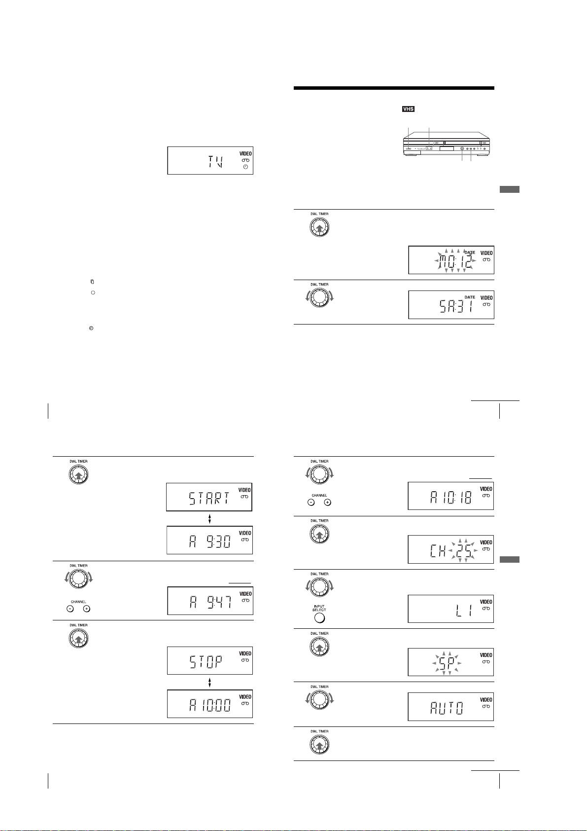
To use the Auto Tape Speed function
When you are recording a program in the Auto mode and the re maining tap e becomes
shorter than the recording time, the tape speed is automatically changed to EP mode.
Note that some noise will appear on the picture when the tape speed is changed. If
you want to keep the tape speed, select SP. To operate this function, set “Tape
Length” in “VIDEO FUNCTION SETUP” menu correctly (page 106).
To watch another TV program after setting the timer
Press TV/VIDEO to display “TV” in the display window.
1
If your TV is connected to the VCR using A/V connections, set the TV to the
2
TV’s antenna input; if not, skip this step.
Select another channel on the TV.
3
To watch a DVD after setting the timer
Press SELECT DVD to control the DVD player.
1
Press Z and place the disc on the disc tray.
2
Press H PLAY.
3
The disc tray closes and the DVD player starts playback. The TV screen will
automatically change to the DVD playback screen.
Tips
• If the indicator appears, the timer settings o v erlap. To check, change or cancel the ti mer
setting, see “Checking/changi ng/canceling timer settings” on page 59.
• If the indicator appears, this means that the VCR is currently recording this program.
•You c an also do the following tasks while the VCR is recording:
–Reset the counter (page 44).
–Display tape information on the TV screen (page 46).
Note
•The indicator flashes in the display window when you complete the timer setting with no
tape inserted.
Recording TV programs using the Dial
Timer
The Dial Timer function allows you to make
timer recordings of programs without turning
on your TV. Set the recording timer to record
up to eight programs that will be broadcast
within a month using the DIAL TIMER. The
recording start time and recording stop time
can be set at one minute intervals.
Before you start…
•Turn on the DVD-VCR.
•When using a cable box, turn it on.
•Insert a tape with its safety tab in place. Make sure the tape is longe r t ha n the to ta l rec ordin g
1
2
time.
(
SLV-D560P
Press DIAL TIMER.
DATE indicator appears and the current date flashes in the display window.
If the date and time are not set, MONTH indicator will appear.
To set the date and time, see “To set the clock” on page 54.
Turn DIAL TIMER to set the recording date.
only)
?/1 POWER
CHANNEL +/–
DIAL TIMER X
Basic Operations
50
Recording TV programs using the timer
3
4
5
Press DIAL TIMER to set the start time.
“START” and the next quarter hour increment appear alternately in the
display window.
Turn DIAL TIMER to set the recording start time.
You can set the recording start time in 15 minute intervals or a djust t he time
in one minute intervals by pressing the CHANNEL +/– buttons on the unit
Press DIAL TIMER to set the stop time.
“STOP” and the next quarter hour increment appear alternately in the
display window.
continued
Recording TV programs using the Dial Timer (SLV-D560P only)
6
7
.
8
9
Turn DIAL TIMER to set the recording stop time.
You can set the recording stop time in 15 minute intervals or adjust the time
in one minute intervals by pressing the CHANNEL +/– buttons on the unit
Press DIAL TIMER.
Current channel flashes in the display window.
Turn DIAL TIMER to set the channel number.
To record from a source connected to the LINE IN 1 or LINE-2 IN jacks,
turn DIAL TIMER or press INPUT SELECT to display “L1” or “L2.”
Press DIAL TIMER.
Current tape speed flashes in the display window.
51
.
Basic Operations
52
Recording TV programs using the Dial Timer (SLV-D560P only)
1-12
10
11
Turn DIAL TIMER to set the tape speed.
Press DIAL TIMER to complete the setting.
“OK” appears in the display window for about five seconds.
The timer indicator appears in the display window and the VCR stands by
for recording. When using a cable box, leave it on.
continued
Recording TV programs using the Dial Timer (SLV-D560P only)
53
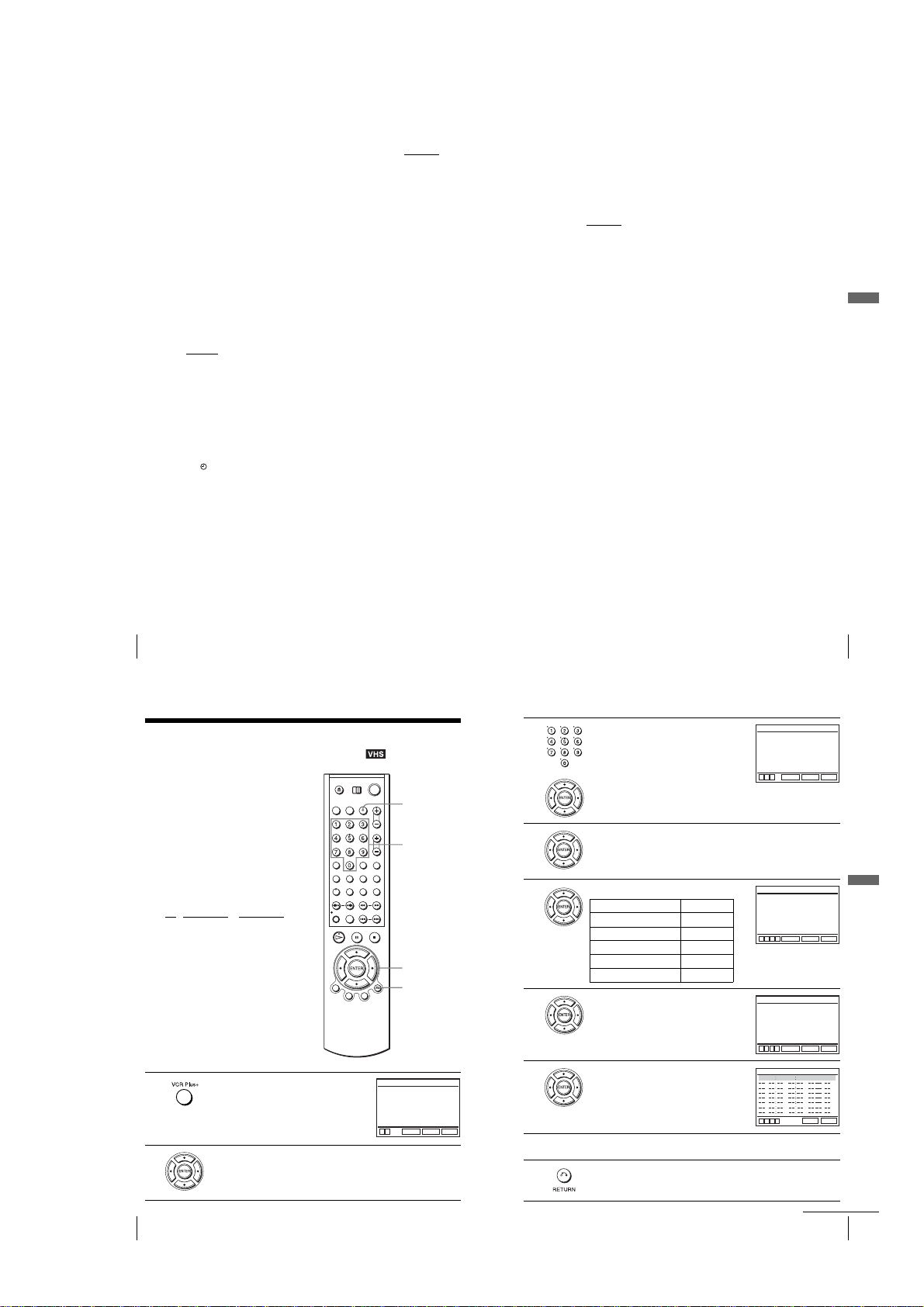
To return to the previous step
To return to the previous step, press the CHANNEL + and – buttons on the unit
same time during any of the Dial Timer settings.
at the
To set the clock
Hold down DIAL TIMER so that MONTH indicator appears in the display
1
window. However, if the clock has already been set , the current setting appears.
Turn DIAL TIMER to set the month.
2
Press DIAL TIMER.
3
DAY indicator appears in the display window.
Turn and press DIAL TIMER to set the day and then the year.
4
After you set the year, “AM” and “12:– –” appear alternately in the display
window.
Turn and press DIAL TIMER to set the hour and minute.
5
When you have finished setting the time, press DIAL TIMER to start the clock.
6
Tips
•To cancel a Dial Timer setting, pres s any button other than DIAL T IMER or CHANNEL +/–
or any button on the remote while you are making the setting.
on the unit
•To check, change, or cancel the program setting, see “Checking/changing/canceling timer
settings” on page 59.
Notes
• If eight programs have already been set using the VCR Plus+ sy st em, DIAL TIMER or the
manual timer setting, “FULL ” ap pe ars in the di sp lay wi ndow for about five secon ds in step1.
• If you set the clock using the Auto Clock Set feature, the clock will adjust itself to the
incoming time signal regardless of adjustments made with the Dial Timer. Be sure you have
set Auto Clock Set correctly.
• If you are setting the clock for the first time or “0:– –” appears in the display window, you
cannot set the clock to February 29
feature to set the VCR to this da y.
•The indicator flashes in the display window when you complete the setting with no tape
inserted.
•When the setting time is incorrect, “Error” appears in the display window when you complete
the timer setting. Set the timer again from step 1.
th
using the Dial Timer. Please use the Auto Clock Set
About the Demonstration Mode
The Dial Timer function has a Demonstration Mode that allows the user, such as a
salesperson, to enter more than eight examples of timer settings when demonstrating
the use of the Dial Timer. It cancels the FULL notice which appears if eight
programs have already been set. Do not use the Demonstrat ion Mode for making
timer recordings. Doing so may cause the settings to be inaccurate.
To activate the Demonstration Mode
Press X on the unit
window for a few seconds.
To cancel the Demonstration Mode
Turn the power off and unplug the AC power cord. Although the Demonstration
Mode is canceled, the timer settings entered while using the Demonstration Mode
will remain. Be sure to manually cancel the timer settings before you use the Dial
Timer or any other timer method after reconnecting the AC power cord (page 59).
while turning the DIAL TIMER. “DEMO” appe ars in the di splay
Basic Operations
54
Recording TV programs using the Dial Timer (SLV-D560P only)
Recording TV programs using the VCR
®
Plus+
Just enter the PlusCode number listed in the
TV program guide. The date, time and
channel number of that program are set
automatically. You can preset up to eight
programs together with the DIAL TIMER
and manual timer settings at one time.
Before you start…
•Check that the DVD-VCR clock is set to
•Turn on the DVD-VCR and your TV.
•Switch the input selector on your TV so
•Set TV
•When using a cable box, turn it on.
•Insert a tape with its safety tab in place.
• If the DVD player is in play mode, you
system
the correct time.
that the signal from the player appears on
the TV screen.
/ DVD·VIDEO to DVD·VIDEO,
then press SELECT VIDEO to control the
VCR (page 10).
Make sure the tape is longer than the total
recording time.
cannot display the setup menu. Stop the
DVD playback.
1
2
56
Recording TV programs using the VCR Plus+® system (SLV-D560P only)
(SLV-D560P only)
Press VCR Plus+.
Press V/v to select “Enter code.”
B
Enter code
Mode
Speed
V
with [0~9]
v
VCR Plus+
Number
buttons
V/v/B/b
ENTER
O RETURN
VCR PLUS+
[ --------- ]
V
RETURN
ENTER
[Once]
[Auto]
SET UP
VCR PLUS+
[012345678]
[Once]
VCR PLUS+
[012345678]
[Once]
VCR PLUS+
[012345678]
[Once]
12/05 Auto
[Auto]
SET UP
[Auto]
SET UP
[Auto]
SET UP
SPEED
CLEAR
55
V
Basic Operations
57
Recording TV programs using the Dial Timer (SLV-D560P only)
3
4
5
6
7
8
9
Press the number buttons to enter the PlusCode
number.
To correct a setting, press B to return to that
setting and reset.
B
Enter code
with [0~9]
Mode
Speed
vVB
ENTER
RETURN
~
Press V/v to select “Mode.”
Press B/b to select the recording pattern:
To record Select
Only once Once
Everyday Monday to Friday Mo~Fr
Every Monday to Saturday Mo~Sa
Everyday Daily
Once a week Weekly
Press V/v to select “Speed.”
Press B/b to select the tape speed, Auto, SP , or
EP, the n press ENTER.
Enter code
with [0~9]
B
Mode
Speed
vVB
b
RETURN
ENTER
Enter code
with [0~9]
Mode
B
Speed
vVB
b
RETURN
ENTER
CH START END DATE
P
P
40
10
M
02
07
07
M
B
vVb
RETURN
To ente r another setting, repeat steps 1 to 7.
Press O RETURN to exit the menu.
The timer indicator appears in the display window and the VCR stands by
for recording. When using a cable box, leave it on.
Recording TV programs using the VCR Plus+® system (SLV-D560P only)
continued
1-13
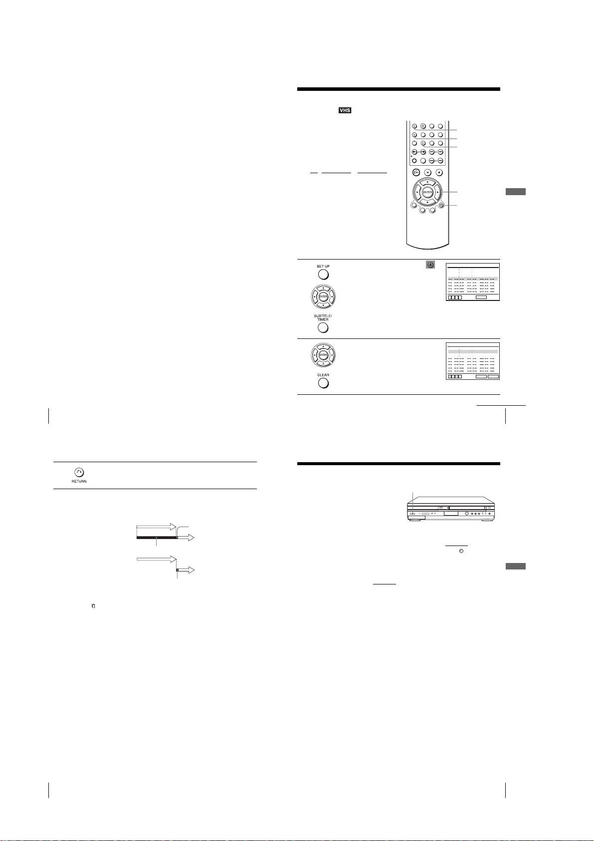
To stop recording
To stop the VCR while recording, press x STOP.
To use the DVD-VCR after setting the timer
To use the DVD-VCR before a timer recording begins, just press ?/1. The timer
indicator disappears from the display window and the DVD-VCR switches on.
Remember to press ?/1 to reset the VCR to the timer recording standby mode after
using the VCR.
You can also do the following tasks while the VCR is recording:
•Reset the counter (page44).
•Display tape information on the TV screen (page46).
•Check the timer settings (page 59).
•Watch another TV program ( page 47).
Tip
•To check, change or cancel the program setting , se e “Checking/changing/canceling timer
settings” on page 59.
Notes
• If the VCR does not accept the PlusCode number, this means th at:
–The PlusCode number is incorrect.
–“Once,” “Daily, ” “M o ~ Sa ,” “Mo~Fr” or “Weekly” was selected incorrectly. You cann o t
select “Daily,” “Mo~Sa,” “Mo~Fr” or “Weekly” for a progra m tha t air s mo re than seven
days ahead.
Correctly set the PlusCode number again from step 2.
•When the PlusCode number is incorrect, “Invalid code” will appear in the display.
Checking/changing/canceling timer
settings
Before you start…
•Check that the DVD-VCR clock is set to
the correct time.
•Turn on the DVD-VCR and your TV.
•Switch the input selector on your TV so
that the signal from the player appears on
the TV screen.
/ DVD·VIDEO to DVD·VIDEO,
•Set TV
then press SELECT VIDEO to control the
VCR (page 10).
•When using a decoder, turn it on.
•Insert a tape with its safety tab in place.
Make sure the tape is longer than the total
recording time.
• If the DVD player is in play mode, you
cannot display the setup menu. St op the
DVD playback.
1
Press SET UP, then press V/v to select
(PROGRAM) and press ENTER. You can also
display the timer programming menu by
pressing TIMER.
The timer programming menu appears.
CLEAR
SET UP
TIMER
V/v/B/b
ENTER
O RETURN
CH START END DATE
01 05 31
03 01 31
06
06 32 08
B
vVb
P
07 31
M
A
M
03 32 1/21
PMP
32
P
M
1/20
A
M
M
RETURN
1/21 EP
SPEED
SP
Auto
Basic Operations
58
Recording TV programs using the VCR Plus+® system (SLV-D560P only)
3
Press O RETURN to confirm the setting.
Press O RETURN again to exit the menu.
When the timer settings overlap
The program that start s fi rst has pr iorit y and t he seco nd pro gram st arts re cord ing only
after the first program has finished. If the programs start at the same time, the
program listed first in the menu has priority.
Program 1
Program 2
will be cut off
Program 1
Program 2
about 20 seconds will be cut off
Tip
• If the indicator appears, the timer settings overlap.
about 20 seconds
2
Press V/v to select setting you want to change
or cancel.
•To change the setting, press B/b to select
the item you want to change, and press V/v
to change it.
•To cancel the setting, press CLEAR.
Checking/changing/canceling timer settings
Locking the DVD-VCR
After you have set the timer, you can lock all
of the buttons on the DVD-VCR so that the
settings are not canceled by mistake.
To lock the DVD-VCR
When the DVD-VCR is turned on, hold down ?/1 POWER on the unit
appears in the display window. The DVD-VCR turns off and the indicator
remains lit if there is a timer setting. The DVD-VCR will not work except for timer
recordings.
To unlock the DVD-VCR
Hold down ?/1 POWER on the unit
window. The DVD-VCR is unlocked and turns on.
To stop timer recording while the DVD-VCR is locked, press x. The recording stops
and the DVD-VCR is unlocked.
Note
•The DVD-VCR will be unlocked when:
–You stop timer recording by pressing
–You insert a tape.
–The AC power cord is disconnected or power supply stops.
(Child Lock)
?/1 POWER
until “LOCK” disappears from the display
x
.
CH START END DATE
P
P
M
01 05 31
07 31
1/20
M
A
A
M
M
03 01 31
03 32 1/21
PMP
06
32
06 32 08
M
B
vVb
RETURN
continued
until “LOCK”
1/21 EP
CLEAR
SPEED
SP
Auto
59
Basic Operations
60
Checking/changing/canceling timer settings
1-14
Locking the DVD-VCR (Child Lock)
61
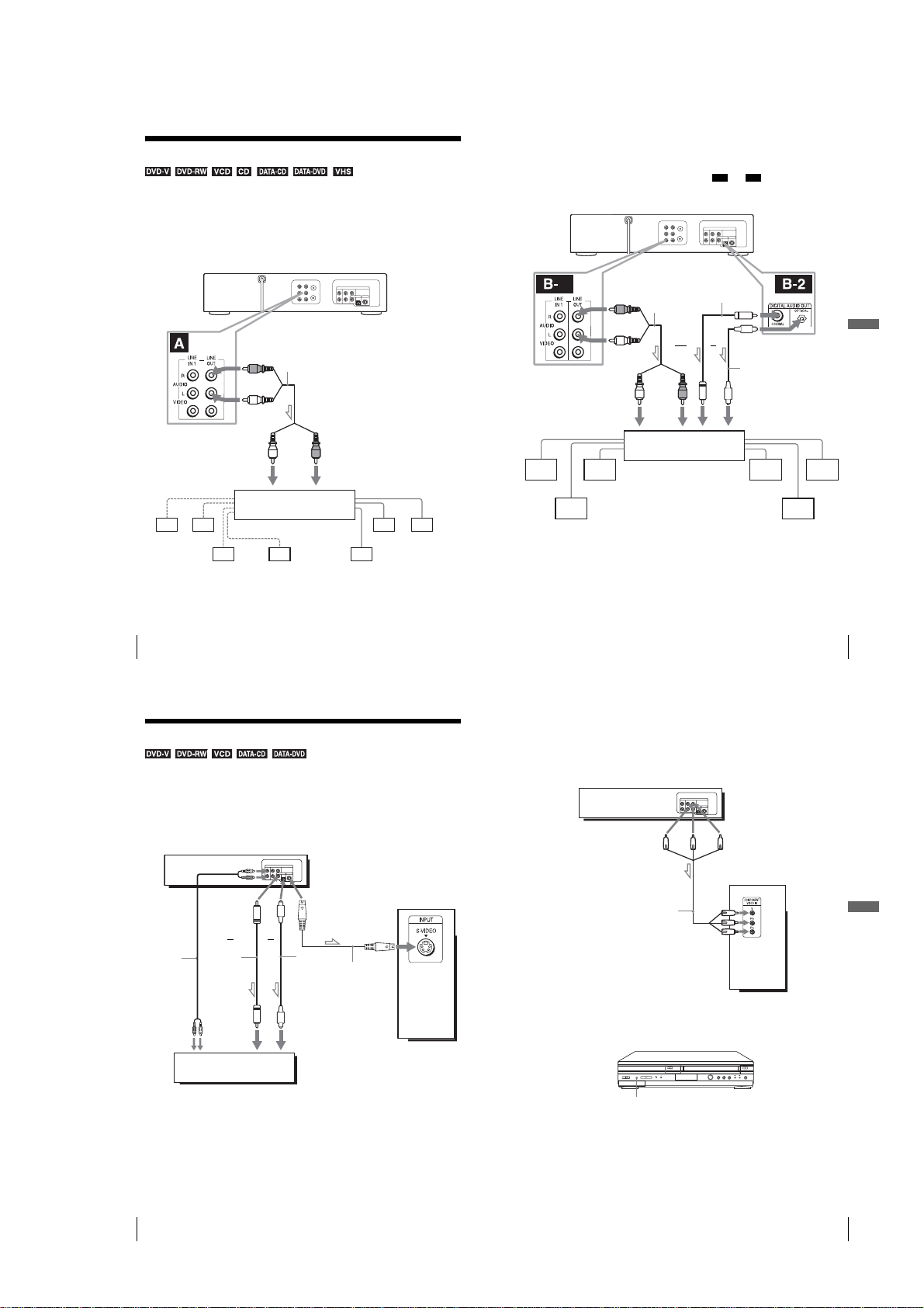
Advanced Hookups
A/V Receiver hookup
A Use this hookup if your A/V receiver has a Dolby* Surround (Pro
Logic) decoder and 3 to 6 speakers
You can enjoy the Dolby Surround effects only when playing Dolby Surround audio
or multi-channel audio (Dolby Digital) discs.
∗ Manufactured under license from Dolby Laboratories. “Dolby”, “Pro Logic”, and the
double-D symbol are trademarks of Dolby Laboratories.
DVD-VCR
B Use this hookup if your A/V receiver has a Dolby Digital or DTS*
decoder, a digital input jack and 6 speakers
This connection will allow you to use the Dolby Digital or DTS decoder function of
your AV amplifier (receiver). Yo u are not able to enjo y the surround sound effects of
this player. You must make connections using and .
∗ “DTS” and “DTS Digital Ou t ” are trademarks of Digital Theater Syste ms, Inc.
1
(red)
DVD-VCR
Stereo audio
cord (not
supplied)
B-1 B-2
Coaxial digital
cord (not supplied)
(red)
Stereo audio cord
(not supplied)
(white)
to LINE OUT L/R (AUDIO)
l : Signal flow
Rear (L)
62
A/V Receiver hookup
(white)
to audio input
[Speakers]
Rear (R)
Note
•When connecting 6 speakers, replace the monaural rear speaker with a center speaker, 2 rear
speakers and a subwoofer.
Subwoofer
Amplifier (receiver) with Dolby
Surround decoder
Center
(red)
[Speakers]
Rear (mono)
S-Video/Component Video hookup
Make audio connections using the LINE OUT AUDIO L/R jacks or DIGITAL AUDIO OUT
(OPTICAL or COAXIAL) jacks on the right side of the DVD-VCR when you use S-VIDEO/
Component Video hookup.
A Use this hookup if your TV has an S-VIDEO input jack
Connect an S-VIDEO cord (not supplied). You will enjoy high quality images.
DVD-VCR
and
(white)
to LINE OUT L/R (AUDIO)
l : Signal flow
Rear (L)
Front (R)Front (L)
Rear (R)
Note
•After you have completed the connection, be sure to set “Dolby Digital” to “Dolby Digital”
(white)
to audio input
[Speakers]
Subwoofer Center
and “DTS” to “On” in “AUDIO SETUP” menu (page 66). Otherwise, no sound or a loud
noise will come from the speakers.
B Use this hookup if your TV has component video input jacks
Connect your TV via the COMPONENT VIDEO OUT jacks using a component
video cord (not supplied) or three video cords (not supplied) of the same kind and
length. You will enjoy accurate color reproduction and high quality images.
See page 62 for audio connections.
(red)
AV amplifier (receiver) having
a decoder
DVD-VCR
or
(blue) (red)
to DIGITAL AUDIO OUT
(COAXIAL or OPTICAL)
Optical digital cord
(not supplied)
Remove jack cap
before connecting
to coaxial or optical
digital input
Front (L)
(green)
[Speakers]
Front (R)
A/V Receiver hookup
Advanced Hookups
63
Audio cord
(not supplied)
to audio
input
TV or AV amplifier
Notes
•The connection using S-VIDEO OUT jack is only for the DVD player.
• If you set “Progressive” to “On” in the “SCREEN SETUP” menu, S-Video playback may be
distorted.
64
S-Video/Component Video hookup
or
Coaxial
digital cord
(not supplied)
or
l : Signal flow
(DVD only)
Optical digital
cord (not
supplied)
Remove jack
cap before
connecting
to coaxial or optical
digital input
S-VIDEO cord
(not supplied)
TV
TV
Component video cord
(not supplied)
l : Signal flow
(DVD only)
If your TV accepts progressive (480p) format signals, you must use this connection
and then set “Progressive” to “On” in the “SCREEN SETUP” menu (page 70). The
PROGRESSIVE indicator lights up in orange when the DVD player outputs
progressive signals.
PROGRESSIVE indicator
Notes
•The connection using COMPONENT VIDEO OUT jack is only for the DVD player.
•Consumers should note that not all high definition television sets are fully compatible with
this product and may cause arti fa cts to be displayed in the picture. In case of 480 progressive
scan picture problems, it is recomm ended that the user switch the connection to the
“
standard definition” output. If there are questions regarding our TV set compatibi li ty w it h
this model 480p DVD player, please contact our customer service center.
(green)
(blue)
(red)
S-Video/Component Video hookup
Advanced Hookups
65
1-15
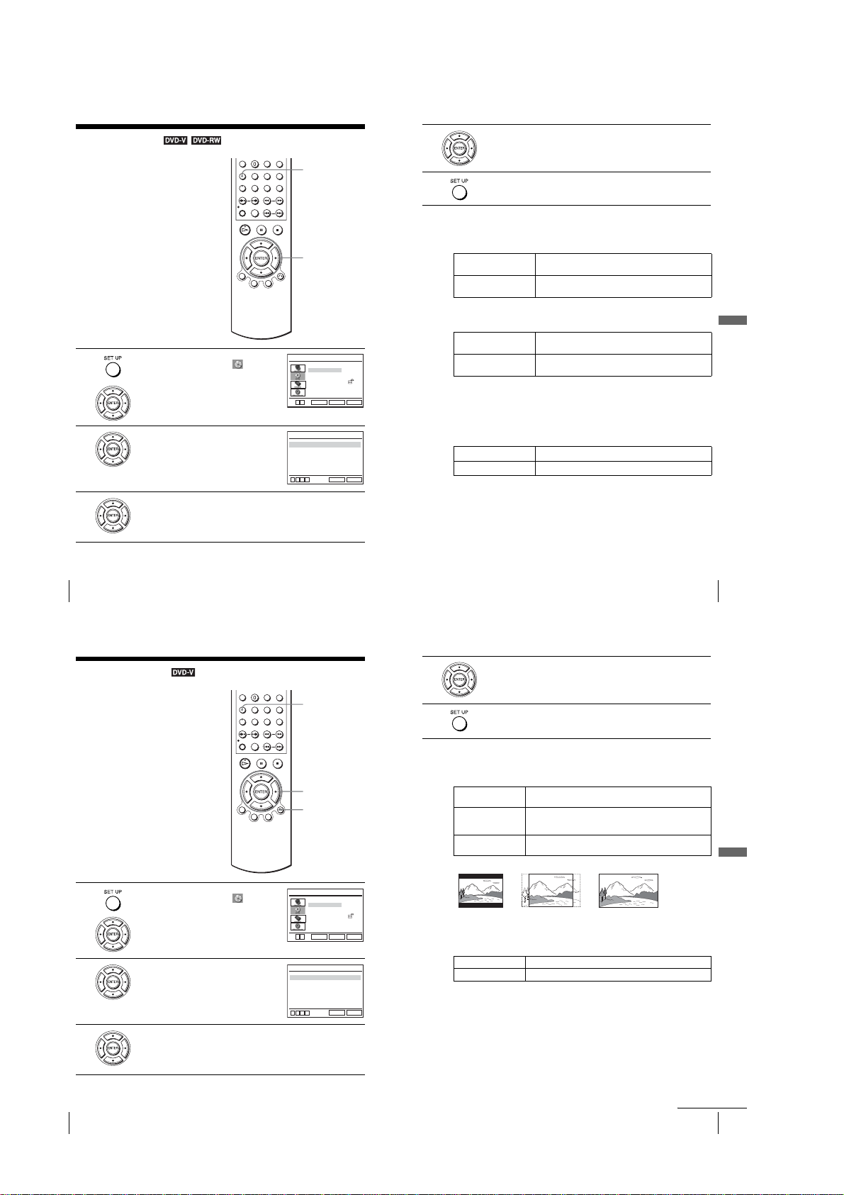
DVD Settings and Adjustments
Audio Setup
“Audio Setup” allows you to set the sound
according to the playback and connection
conditions.
1
2
3
Press SET UP when the DVD player is in stop
mode, then press V/v to select (DVD),
then press ENTER.
Press V/v to select “Audio Setup,” then press
ENTER.
Press V/v to select the setup item from the displayed list:
“Dolby Digital,” “DTS” or “Audio DRC.”
V v
Dolby Digital
DTS
Audio DRC
B
vVb
SET UP
V/v/B/b
ENTER
Language Setup
Audio Setup
Screen Setup
Parental Setup:
ENTER
DVD SETUP
RETURN
AUDIO SETUP
[ D-PCM ]
[ Off ]
[ Standard ]
RETURN
SET UP
SET UP
4
5
Press B/b to select an item.
Press SET UP to exit the menu.
Menu choices
•Dolby Digital
Selects the type of Dolby Digital signal.
The default setting is indicated in bold print.
D-PCM Select this when the player is connected to an aud io comp onent
Dolby Digital Select this when the player is connected to an aud io comp onent
•DTS
Selects whether or not to output DTS signals.
The default setting is indicated in bold print.
Off Select this when the player is co nnecte d to a n audio co mponen t
On Select this when the player is connected to an audio co mponent
•Audio DRC (Dynamic Range Control)
Makes the sound clear when the volume is turned down when playing a DVD that
conforms to “Audio DRC.” This affects the output from the following jacks:
–LINE OUT AUDIO L/R jacks
–DIGITAL AUDIO OUT (OPTICAL or COAXIAL) jack only when “Dolby
Digital” is set to “D-PCM”.
The default setting is indicated in bold print.
Standard Normally select this positon.
Wide Range Gives you the feeling of being at alive performance.
Notes
•If you select the surround setting while playing a DVD, the pl ayer does not output Dolby
Digital signals from the DIGITAL AUDIO OUT (OPTICAL or COAXIAL) jack (when you
set “Dolby Digital” to “D-PCM” in “AUDIO SETUP” menu).
•If you connect a component that does not conform to the selected audio signal, a loud noise
(or no sound) will come out from the speakers, affecting your ears or causing the speakers to
be damaged.
•Noise may occur in the LinearPCM double-spe ed audio. This is not a malfunction.
•If you set “DTS” to “On,” you cannot select surround setting (p age 88).
•You cannot perform DTS audio output during playback quickly or slowly with sound (p age 36).
lacking a built-in Dolby Digital decoder.
with a built-in Dolby Digital decoder.
lacking a built-in DTS decoder.
with a built-in DTS decoder.
DVD Settings and Adjustments
66
Audio Setup
Screen Setup
“Screen Setup” allows you to set the screen
according to the playback and connection
conditions.
1
2
3
Press SET UP when the DVD player is in stop
mode, then press V/v to select (DVD),
then press ENTER.
Press V/v to select “Screen Setup,” then press
ENTER.
Press V/v to select the setup item from the displayed list:
“TV Type,” or “Black Level.”
To set the “Progressive” setting, see page 70.
v
V
TV Type
Black Level
Progressive
B
vVb
SET UP
V/v/B/b
ENTER
O RETURN
Language Setup
Audio Setup
Screen Setup
Parental Setup:
RETURN
ENTER
SCREEN SETUP
[
4:3 Letter Box
RETURN
DVD SETUP
SET UP
[
Off
[
Off
SET UP
Audio Setup
4
5
]
]
]
Press B/b to select an item.
Press SET UP to exit the menu.
Menu choices
•TV Type
Selects the aspect ratio of the connected TV (4:3 standard or wide).
The default setting is indicated in bold print.
4:3 Letter Box Select this when you connect a 4:3 screen TV. Displays a wide
4:3 Pan Scan Select this when you connect a 4:3 screen TV. Automatically
16:9 Select this when you connect a wide-screen TV or a TV wi th a wide
•Black Level
You can enhance the black level by increasing the brightness and contrast when
viewing DVD VIDEOs with the PROGRESSIVE indicator turned off.
The default setting is indicated in bold print.
Off Stops the increase of the contrast.
On Increases the cont ras t.
Notes
•Playback settings stored in the disc take priority over the “DVD SETUP” menu settings and
not all the functions described may work.
•Depending on the DVD VIDEO, “4:3 Letter Box” may be selected automatically instead of
“4:3 Pan Scan” or vice versa.
picture with bands on the upper and lower portions of the scre en.
displays the wide picture on the entire screen and cuts off the
portions that do not fit.
mode function.
4:3 Pan Scan4:3 Letter Box 16:9
67
DVD Settings and Adjustments
68
Screen Setup
1-16
continued
Screen Setup
69
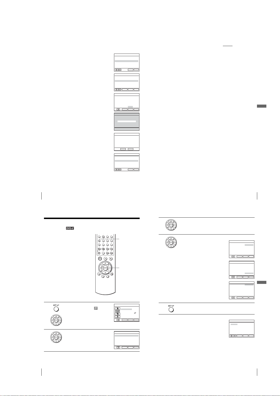
To set the “Progressive” setting
If your TV accepts progressive (480p) format signals, you will enjoy accurate color
reproduction and high quality image.
Follow step 1 and 2 on page 68, then press V/v to
1
select “Progressive.”
Press B/b to select “On,” then press ENTER.
2
Follow the instructions appearing on the screen.
3
1
Ensure your TV is (480p) Progressive Scan
capable.
2
Connect with Component Video Output jacks
(red/green/blue connections).
See “Use this hookup if your TV has comp onent
video input jacks” on page 65.
3
Press B/b to select [OK] to test your video
signal.
SCREEN SETUP
[
TV Type
4:3 Letter Box
RETURN
SCREEN SETUP
[
4:3 Letter Box
RETURN
ENTER
SCREEN SETUP
OK CANCEL
RETURN
ENTER
SCREEN SETUP
TEST SCREEN
[
[
[
[On ]
Black Level
Progressive
B
vVb
TV Type
Black Level
Progressive
B
vVb
Progressive Scan Output
1) Ensure your TV is (480P) Progressive
Scan capable.
2) Connect with Component Video Output
jacks. (red/green/blue connections)
3) Select [OK] to test your video signal.
4) If video signal appears OK,
video connection is complete.
B
b
Off
Off
SET UP
Off
SET UP
SET UP
Tip
•The “Progressive” setting can be canceled by pressing X on the unit
seconds or more, or selecting “Off” in step 2.
Note
•If you select progressive signal when you connect the DVD player to a TV that cannot accept
]
]
]
]
]
the signal in progressive format, the image quality will deteriorate. In this case, set
“Progressive” to “Off”.
continuously for 5
DVD Settings and Adjustments
If video signal appears OK, video connection is
4
complete. Press ENTER.
The PROGRESSIVE indicator on the unit lights up
in orange.
If picture is distorted, press O RETURN.
Check the connection (page 65).
Press SET UP to exit the menu.
5
70
Screen Setup
Setting the display or sound track
language
You can set various languages for th e disc’s
menu, sound track or subtitle.
Press
SET UP
1
2
when the DVD player is in stop
mode, then press V/v to select (DVD) and
ENTER
.
press
Press V/v to select “Language Setup,” then
press ENTER.
The “LANGUAGE SET UP” menu appears.
SCREEN SETUP
If picture is OK, press [ENTER] key.
If picture is distorted, press [RETURN] key.
To Deactivate
Press [PAUSE] on the unit for 5 seconds.
RETURN
ENTER
SCREEN SETUP
[
TV Type
4:3 Letter Box
Black Level
Progressive
B
vVb
RETURN
SET UP
V/v/B/b
ENTER
DVD SETUP
Language Setup
Audio Setup
Screen Setup
Parental Setup:
v
V
RETURN
ENTER
LANGUAGE SETUP
DVD Menu
: English
: Original
Audio
Subtitle
: Audio Follow
v
V
RETURN
ENTER
[
[On ]
Off
SET UP
SET UP
SET UP
]
]
English
Français
Deutsch
Español
Italiano
Nederlands
Others
SET UP
English
Français
Deutsch
Español
Italiano
Nederlands
Original
Others
SET UP
Audio Follow
English
Français
Deutsch
Español
Italiano
Nederlands
Others
SET UP
Hindi
Japanese
Russian
Turkish
Thai
Korean
SET UP
71
DVD Settings and Adjustments
3
4
5
Press V/v to select the language setup item from the displayed list:
“DVD Menu,” “Audio,” or “Subtitle.”
Then press ENTER.
Press V/v to select the desired language, then press ENTER.
•DVD MENU LANGUAGE
You can select the desired langua g e for the
disc’s menu.
•AUDIO LANGUAGE
Switches the language of the sound track.
When you select “Original,” the language
given priority in the disc is selected.
•SUBTITLE LANGUAGE
Switches the language of the subtitle
recorded on the DVD VIDEO.
When you select “Audio Follow,” the
language for the subtitle changes according
to the language you selected for the sound
track.
Press SET UP to exit the menu.
Tip
•If you select “Others” in step 4, an additional language menu
appears. Press V/v/B/b to select the desired language,
then press ENTER.
Notes
•When you select a language that is not recorded on the DVD
VIDEO in step 4, one of the recorded languages will be automatically selected.
•Playback settings stored in the disc take priority over the DVD SETUP settings and not all the
functions described may work.
V
DVD Menu
v
V
Audio
v
V
Subtitle
v
V
Cesky
Dansk
Magyar
Svenska
Norsk
Polski
v
B
b
Screen Setup
DVD MENU LANGUAGE
B
RETURN
ENTER
AUDIO LANGUAGE
B
RETURN
ENTER
SUBTITLE LANGUAGE
B
RETURN
ENTER
DVD MENU LANGUAGE
Português
Suomi
Afrikaans
Arabic
Chinese
Greek
RETURN
ENTER
72
Setting the display or sound track language
1-17
Setting the display or sound track language
73
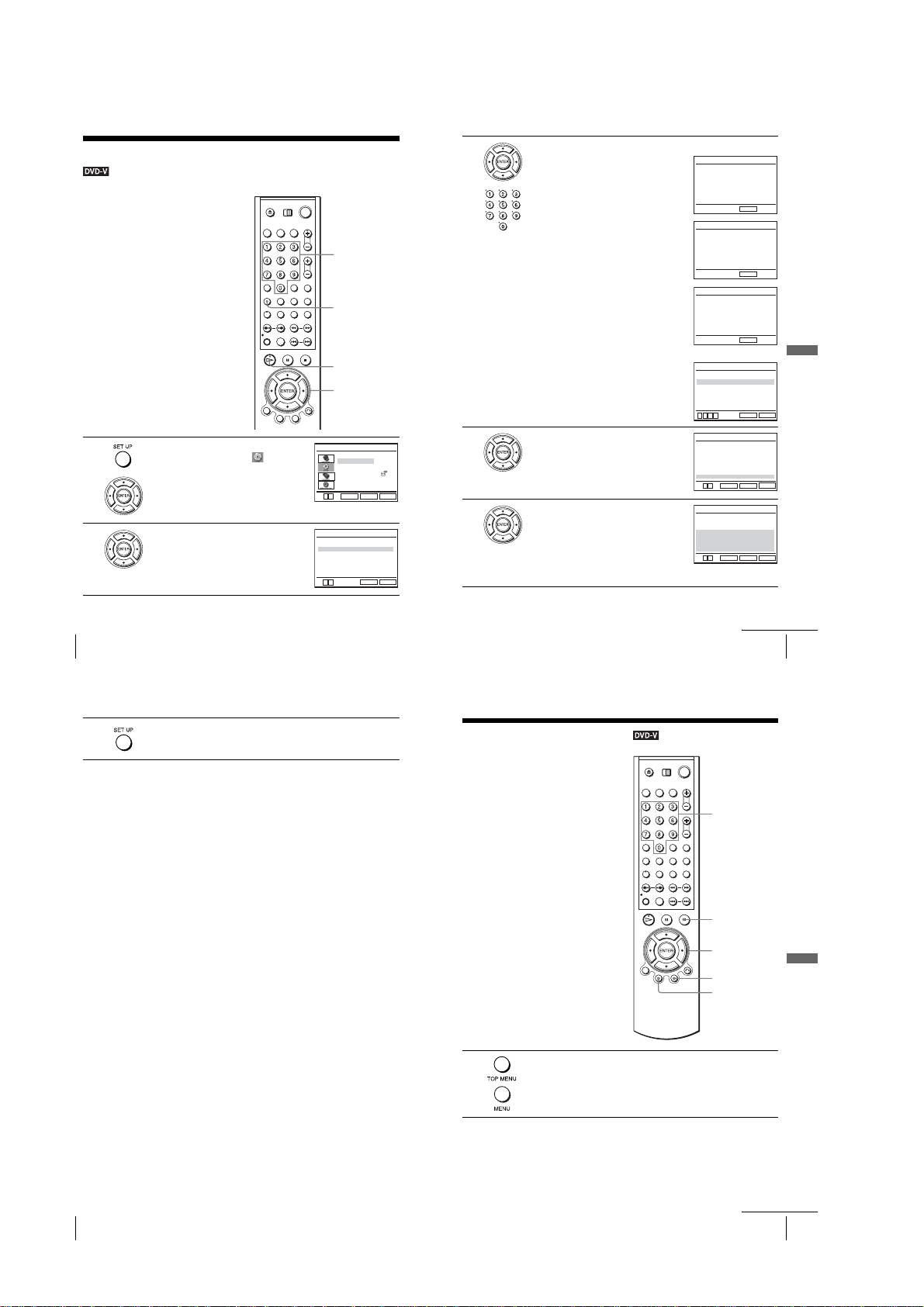
Parental Control
Playback of some DVD VIDEOs can be
limited according to a predetermined level
such as the age of the users. The “Parental
Control” function allows you to set a
playback limitation level.
1
2
Press SET UP when the DVD player is in stop
mode, then press V/v to select (DVD) and
press ENTER.
Press V/v to select “Parental Setup,” then
press ENTER.
(limiting playback by children)
v
V
Use Password
b
B
Number
buttons
SET UP
H PLAY
V/v/B/b
ENTER
Language Setup
Audio Setup
Screen Setup
Parental Setup:
ENTER
PARENTAL SETUP
RETURN
RETURN
DVD SETUP
SET UP
[ No ]
SET UP
3
4
5
Press b to set the parental control.
• If you have not entered a password
The display for registering a new pa ssword
appears.
Enter a 4-digit password using the numb er
buttons.
The display for confirming the password
appears.
Re-enter the password.
•When you have already registered a
password
The display for entering the password appears.
Enter a 4-digit password using the numb er
buttons.
After registering a password, if you se t
Password
” to “No,” “
screen will not appear.
Press V/v to select “Rating Level,” then press
ENTER.
Press V/v to select the level you want, then
press ENTER.
PASSWORD CHECK
“
Use
The options are as follows.
Level 8 (Adult) y Level 7 y Level 6 y
Level 5 y Level 4 y Level 3 y Leve l 2
y Level 1 (Kids Safe)
”
Enter Password
-~9
Re-enter Password
-~9
Enter Password
-~9
Use Password
Rating Level
Change Password
B
vVb
Level 8 Adult
Level 7
Level 6
Level 5
Level 4
Level 3
Level 2
Level 1 Kids Safe
v
V
ENTER
Level 8 Adult
Level 7
Level 6
Level 5
Level 4
Level 3
Level 2
Level 1 Kids Safe
v
V
ENTER
CREATE PASSWORD
––––
RETURN
CREATE PASSWORD
––––
RETURN
PASSWORD CHECK
––––
RETURN
PARENTAL SETUP
[ Yes ]
:1
RETURN
RATING LEVEL
RETURN
RATING LEVEL
RETURN
DVD Settings and Adjustments
SET UP
SET UP
SET UP
The lower the value, the stricter the limitation.
74
Parental Control (limiting playback by children)
6
Press SET UP to exit the menu.
To change the password
Select “Change Password” in step 4 on page75.
1
The display for entering a new password appears.
Enter a new 4-digit password using the number buttons.
2
The display for confirming the password appears.
Re-enter the new password.
3
To turn off the Parental Control function
Set “Use Password” to “No” in step 3 on page 75.
To play a disc for which Parental Control is set
Insert the disc, then press H PLAY.
1
The display for entering your password appears.
Enter your 4-digit password using the number buttons.
2
The player starts playback.
If you forget your password
Turn on the DVD-VCR.
1
Remove the disc and close the disc tray.
2
Hold down m and M on the front panel simultaneously fo r 5 seconds.
3
“Reset OK” appears on the screen.
Turn off the DVD-VCR.
4
The password is cleared.
To create a new password, follow step 3 on pag e 75.
5
Notes
•When you play DVD VIDEOs which do not have the Parental Control function, playback
cannot be limited on this player.
•All the ratings higher than the level you select will b e bl ocked.
•Write your password down and keep it in a safe place in case you forget it.
DVD Additional Operations
Using the DVD’s menu
A DVD is divided into long sections of a
picture or a music feature called “titles.”
When you play a DVD VIDEO which
contains several titles, you can select the title
you want using the TOP MENU button.
When you play DVD VIDEOs that allow you
to select items such as the language for the
subtitles and the language for the sound,
select these items using the MENU button.
1
Press TOP MENU or MENU
The disc’s menu appears on the TV screen.
The contents of the menu vary from disc to disc.
continued
Parental Control (limiting playback by children)
Number
buttons
x STOP
V/v/B/b
ENTER
MENU
TOP
MENU
.
75
DVD Additional Operations
76
Parental Control (limiting playback by children)
1-18
continued
Using the DVD’s menu
77
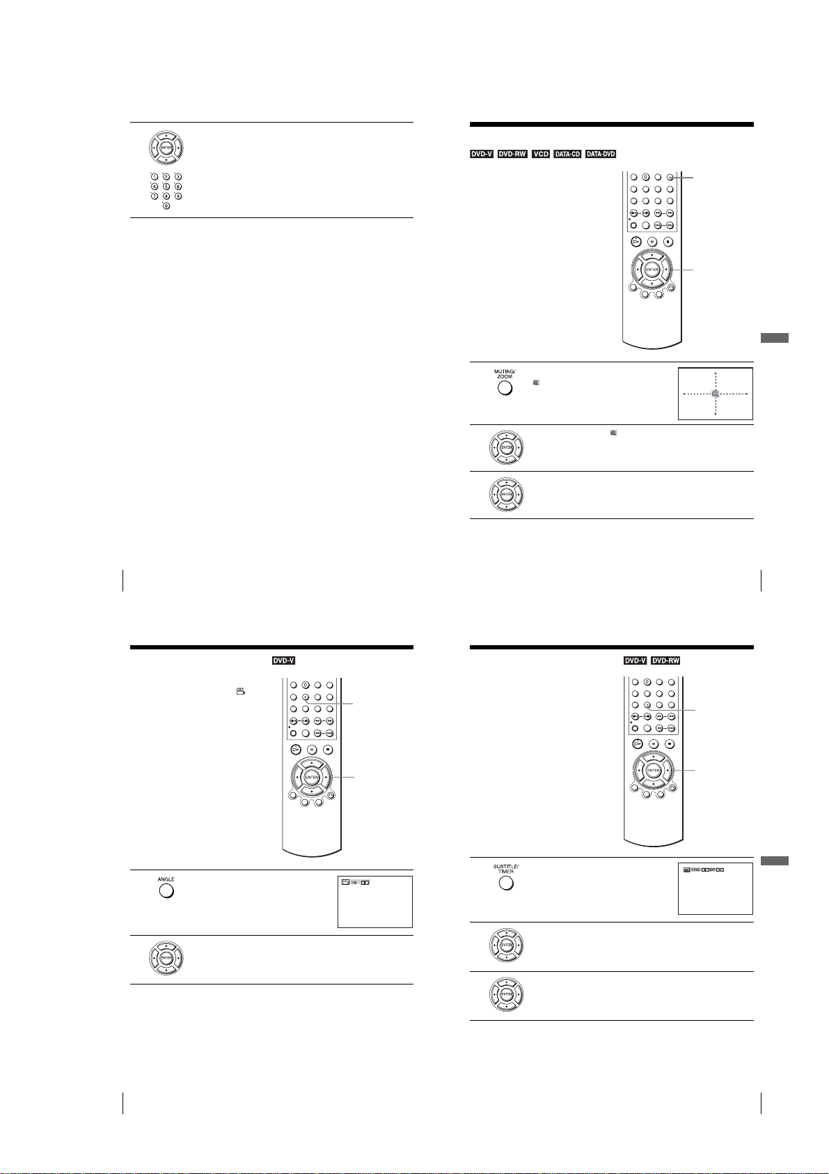
2
Press V/v/B/b to select the item you want to play or change, then press
ENTER.
You can also use the number buttons to select the item.
Note
•Depending on the DVD VIDEO, you may not be able to use the TOP MENU button or search
a point by setting the time.
Zooming into a scene
You can zoom into a scene during playback
or still mode. To zoom into a JPEG image,
see “Playing JPEG image files” on page 95.
ZOOM
V/v/B/b
ENTER
DVD Additional Operations
78
Using the DVD’s menu
Changing the angles
If various angles (multi-angles) for a scene
are recorded on the DVD VIDEO, “ ”
appears in the display window. This means
that you can change the viewing angle.
ANGLE
B/b
1
2
3
Press ZOOM.
“” appears.
Press V/v/B/b to move “ ” to the position where you want to zoom in.
Press ENTER repeatedly to change the magnification.
Each time you press the button, the magnification changes as shown below.
2× t 4× t 2× t normal magnificatio n
Notes
•You cannot use 4
•The zoom function may not work depending o n the DVD.
×
magnification when you play VIDEO CDs.
Displaying the subtitle
If subtitles are recorded on the disc, you can
change the subtitles or turn them on and off
whenever you want while playing a DVD.
Zooming into a scene
SUBTITLE
V/v/B/b
79
1
2
80
Changing the angles
Press ANGLE during playback.
The angle number appears on the display.
The number after the slash indicates the total
number of angles.
Press B/b repeatedly to select the angle nu mber.
The scene changes to the selected angle.
Note
•Depending on the DVD VIDEO, you may not be able to change the angles even if multiangles are recorded on the DVD VIDEO.
bB
1-19
1
2
3
Press SUBTITLE during playback.
Press B/b repeatedly to select the language.
Depending on the DVD, the choice of language varies .
Refer to “DVD Audio/Subtitle Language ” on p age126 for the abbreviati on
of the language.
Press V/v repeatedly to select “On.”
To turn off the subtitles
Select “Off” in step 3.
Note
•Depending on the DVD, you may not be able to change the subtitles even if multilingual
subtitles are recorded on it. You also may not be able to turn them off.
B
vVb
Displaying the subtitle
DVD Additional Operations
81
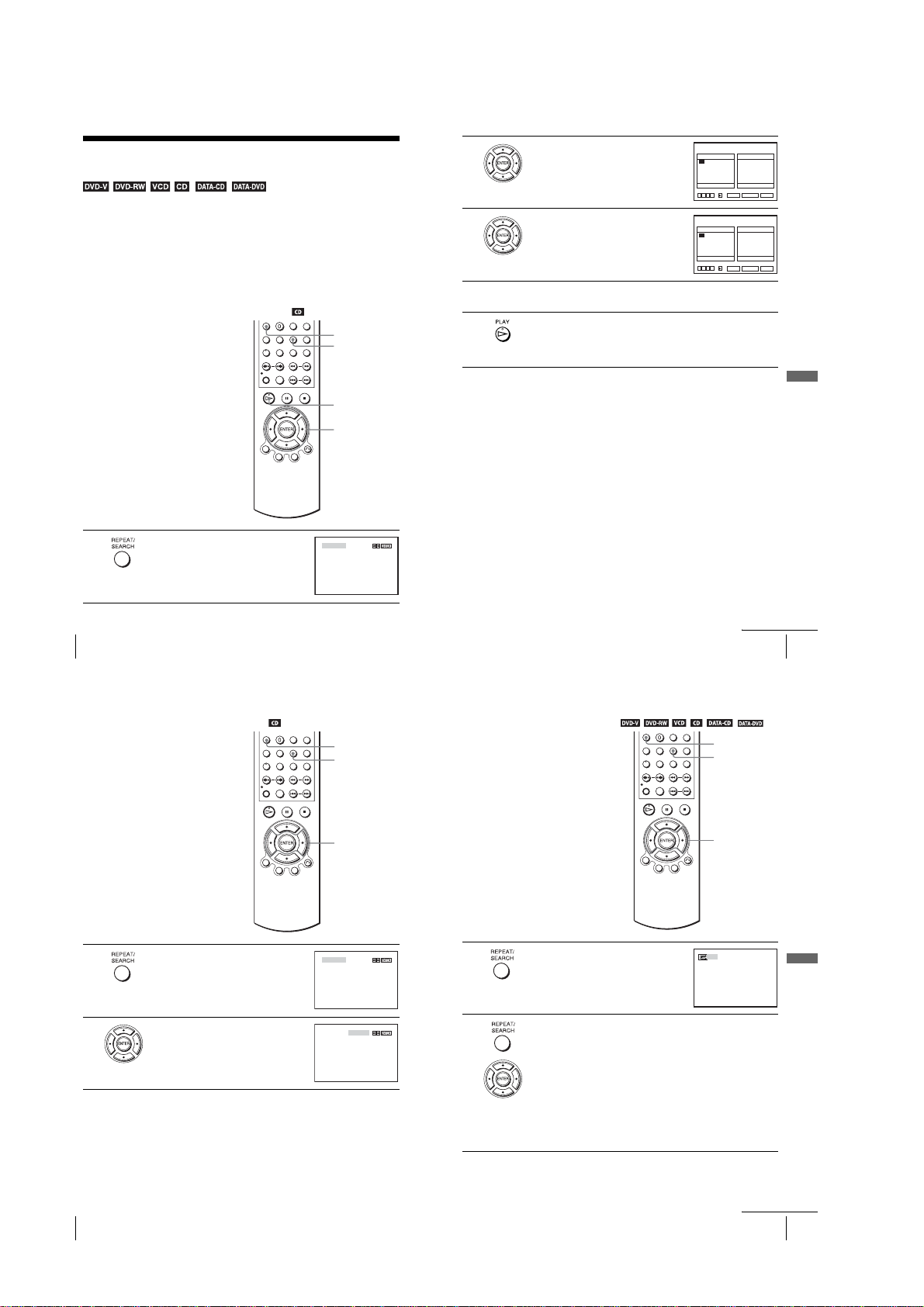
Various play mode functions
Shuffle play, Repeat play)
You can set the following play modes:
•Program play (page 82), Program play MP3 audio tracks (page 92)
•Shuffle play (page 84), Shuffle play MP3 audio tracks (page 93)
•Repeat play (page 85)
Note
•The play mode is canceled when:
–you open the disc tray
–the play er e n ters standby mode by pressing [/1.
Creating your own program (Program play)
You can play the contents of a disc in the
order you want by arranging the order of the
tracks on the disc to create your own
program. You can program up to 20 tracks.
To prog ram MP3 audio tracks, see page 92.
1
82
Various play mode functions (Program play, Shuffle play, Repeat play)
Press REPEAT when the DVD player is in stop
mode.
(Program play,
CLEAR
REPEAT
H PLAY
V/v/B/b
ENTER
PROGRAM SHUFFLE
2
3
4
5
Press B/b to select “PROGRAM”, then press
ENTER.
Press V/v/B/b to select the track number you
want to program, then press ENTER.
To prog ram other tracks, repeat step 3.
The programmed track numbers are displayed in the selected order.
Press H PLAY to start program play.
Program play starts.
When the program ends, you can restart the same program again by
pressing H PLAY.
To stop program play
Press CLEAR until “Off” appears at the upper left top of the TV screen during
programme play.
To change or cancel a program
Follow steps 1 and 2 of “Creating your own progra m (P rogram play).”
1
Press v repeatedly to select “Clear last track,” then press ENTER. Each time you
2
press the button, the last programmed number is canceled. You can also cancel
the last programmed number by pressing CLEAR.
Follow step 3 for new programming.
3
To cancel all the programmed numbers
Follow steps 1 and 2 of “Creating your own progra m (P rogram play).”
1
Press v repeatedly to select “Clear last track,” then press b to select “Clear all
2
tracks” and press ENTER.
All the programmed numbers are canceled.
Notes
•Up to 99 tracks can be displayed.
•Up to 20 tracks can be programmed at one time.
Various play mode functions (Program play, Shuffle play, Repeat play)
PROGRAM
Track Program Order
04
03
02
01
05
09
13
17
Clear last track Clear all tracks
vVb
PROGRAM
01
05
09
13
17
Clear last track Clear all tracks
vVb
––
––
07
––
06
08
––
––
11
––
12
10
––
15
––
16
14
B
18
20
––
19
––
B
RETURN CLEAR
ENTER
Track Program Order
02
04
––
03
01
––
06
08
––
07
––
––
12
11
10
––
15
––
14
16
B
––
19
––
18
20
B
RETURN CLEAR
ENTER
continued
––
––
––
––
––
––
––
––
––
––
––
––
––
––
––
––
––
––
––
––
DVD Additional Operations
83
Playing in random order (Shuffle play)
You can shuffle the playback order of tracks.
Subsequent “shuffling” may produce a
different playing order.
To shuffle MP3 audio tracks, see page 93.
1
2
Press REPEAT when the DVD player is in stop
mode.
Press B/b to select “SHUFFLE”, then press
ENTER.
To return to normal play
Press CLEAR until “Off” appears at the upper left top of the TV screen during shuffle
play.
Tips
•Shuffle play will stop when all the tracks are played back.
•You cannot repeat play while in shuffle play.
CLEAR
REPEAT
B/b
ENTER
PROGRAM SHUFFLE
PROGRAM SHUFFLE
Playing repeatedly (Repeat play)
You can play all of the titles or tracks on a
disc or a single title, chapter, or track
repeatedly.
CLEAR
REPEAT
B/b
1
2
Press REPEAT during playback.
Press REPEAT or B/b repeatedly to select the item to be repeated.
When playing a DVD
•Chapter: repeats the current chapter.
•Title: repeats the current title on a disc.
When playing a VIDEO CD (with PBC function off) or CD
•Track: repeats the current track.
•Disc: repeats all of the tracks.
When playing a DATA CD/DATA DVD (MP3 audio)
•FILE: repeats the current track (file).
•DIR: repeats the current album (directory).
•DISC: repeats the current disc.
Off
DVD Additional Operations
84
Various play mode functions (Program play, Shuffle play, Repeat play)
1-20
continued
Various play mode functions (Program play, Shuffle play, Repeat play)
85
 Loading...