

Sony MHC-GTR888, MHC-GTR777, MHC-GTR333, MHC-GTR555, MHC-GPX8 Operating Instructions Manual
...
4-270-420-12(1)
Mini HI-FI
Component System
Operating Instructions
Getting Started
Disc
Tuner
USB Device
Sound Adjustment
Other Operations
Additional Information
MHC-GTR888/GTR777/GTR555/GTR333
WARNING
To reduce the risk of f ire or electric shock, do
not expose this apparatus to rain or moisture.
To reduce the risk of fire, do not cover the
ventilation opening of the apparatus with
newspapers, tablecloths, curtains, etc.
Do not place the naked flame sources such as
lighted candles on the apparatus.
To reduce the risk of f ire or electric shock, do
not expose this apparatus to dripping or
splashing, and do not place objects filled
with liquids, such as vases, on the apparatus.
As the main plug is used to disconnect the
unit from the mains, connect the unit to an
easily accessible AC outlet. Should you
notice an abnormality in the unit, disconnect
the main plug from the AC outlet
immediately.
Do not install the appliance in a confined
space, such as a bookcase or built-in cabinet.
Do not expose batteries or apparatus with
battery-installed to excessive heat such as
sunshine, fire or the like.
The unit is not disconnected from the mains
as long as it is connected to the AC outlet,
even if the unit itself has been turned off.
CAUTION
The use of optical instruments with this
product will increase eye hazard.
License and Trademark Notice
• “WALKMAN” and “WALKMAN” logo
are registered trademarks of Sony
Corporation.
• MPEG Layer-3 audio coding technology
and patents licensed from Fraunhofer IIS
and Thomson.
• Windows Media is either a registered
trademark or trademark of Microsoft
Corporation in the United States and/or
other countries.
• This product contains technology subject
to certain intellectual property rights of
Microsoft.
Use or distribution of this technology
outside of this product is prohibited
without the appropriate license(s) from
Microsoft.
This appliance is classified as a CLASS 1
LASER product. This marking is located on
the rear exterior.
GB
2

Table of Contents
Guide to parts and controls ..........4
Getting Started
Hooking up the system
securely ........................................8
Positioning the speakers.............10
Setting the clock.........................11
Disc
Playing an AUDIO CD/MP3
disc .............................................12
Using play mode ........................12
Tuner
Listening to the radio .................14
Receiving RDS broadcasts.........15
USB Device
Before using the USB device
with this system..........................15
Transferring music .....................16
Playing a file ..............................19
Sound Adjustment
Adjusting the sound ...................20
Creating your own sound
effect ..........................................21
Creating a party atmosphere
(DJ EFFECT) .............................21
Other Operations
Singing along ............................ 22
Changing the lighting pattern
on the speakers .......................... 22
Using the timers ........................ 22
Changing the display................. 23
Using optional equipment ......... 24
Deactivating the buttons on the
unit (Child Lock)....................... 24
Additional Information
Playable discs ............................ 25
Troubleshooting ........................ 26
Messages ................................... 30
Precautions ................................ 31
Specifications ............................ 32
In this manual, the MHC-GTR888 is
used for illustration purpose unless
stated otherwise.
GB
3
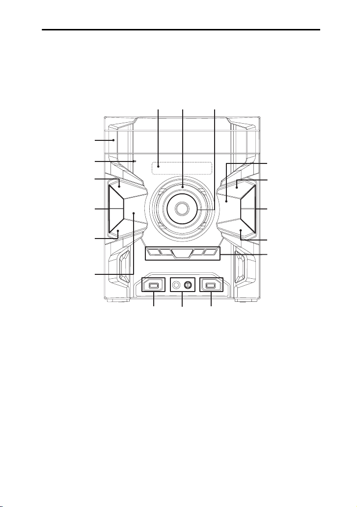
Guide to parts and controls
This manual mainly explains operations using the unit, but the same operations can also
be performed using the buttons on the remote control having the same or similar names.
Unit
45 6
3
2
1
9
qg
7
* MHC-GTR888/MHC-GTR777 only.
qf
qd
7
8
9
q;
qa
*
qs
GB
4

Remote control RM-AMU053
ws
wa
w;
ql
BAND
7
qk
qa
6
1
"/1 (on/standby)
Turn on the system, or set it to standby
mode.
B
Remote control sensor
C
Disc tray
D
Display panel
E
Unit: VOLUME/DJ CONTROL
Adjust the volume.
Adjust the DJ EFFECT level (page 21).
You cannot use this knob to adjust the
volume when the DJ EFFECT is
activated.
Remote control: VOLUME +/–*
Adjust the volume.
* The VOLUME + button has a tactile dot. Use
the tactile dot as a reference when operating
the system.
1
qh
qj
9
6
6
9
6
5
F
Unit: / / /
Select the menu items.
+/– (select folder)
Select a folder on an MP3 disc or a USB
device.
m/M (rewind/fast forward)
Hold down to find a point in a track or file
during playback.
./> (go back/go forward)
Select a track or file.
Unit: TUNING +/–
Remote control: +/– (tuning)
Tune to the station you want.
ENTER
Enter the settings.
G
Unit: NX (play/pause)
Remote control: N (play),
X (pause)
Start or pause playback.
To resume playback of the USB device,
press NX or N.
x (stop)
Stop playback.
Press x twice to cancel resume playback
of the USB device.
H
Z OPEN/CLOSE
Insert or eject a disc.
Continued
l
GB
5

I
FUNCTION
Select a function.
Unit: CD/DISC SKIP
Select the CD function.
Select a disc during CD function.
Unit: USB/USB SELECT
Select the USB function.
Select the USB device connected to the
A or B port during USB function.
Remote control: CD
Select the CD function.
Remote control: USB
Select the USB function.
Remote control: DISC SKIP/USB
SELECT
Select a disc during CD function.
Select the USB device connected to the
A or B port during USB function.
Unit: TV
Select the TV function.
Remote control: TUNER/BAND
Select the TUNER function.
Select the FM or AM band during
TUNER function.
J
EX-CHANGE
Exchange other discs during playback.
K
Unit: PRESET EQ
Remote control: EQ
Select the sound effect (page 20).
Unit: GROOVE
Reinforce the bass.
Unit: DJ EFFECT (page 21)
Activate the DJ EFFECT.
Unit: FLANGER, ISOLATOR,
SOUND FLASH, PHASER (page 21)
Select the DJ EFFECT type.
Unit: OPTIONS
Enter the option menus.
Unit: SEARCH
Enter or exit search mode.
L
B (REC/PLAY) port
Connect and transfer to an optional USB
device.
B indicator
Lights up in red when transferring to the
connected optional USB device.
M
MIC jack
Connect a microphone.
MIC LEVEL
Adjust the microphone volume.
N
A (PLAY) port
Connect an optional USB device.
A indicator
O
REC TO USB B
Transfer onto the optional USB device
which is connected to the B port.
GB
6

P
CLOCK/TIMER SELECT (page 23)
CLOCK/TIMER SET (page 11, 23)
Set the clock and the timers.
Q
REPEAT/FM MODE
Listen to a disc, a USB device, a single
track or file repeatedly (page 13, 20).
Select the FM reception mode (monaural
or stereo) (page 14).
R
CLEAR
Delete the last step from the program list.
S
TUNER MEMORY (page 14)
Preset the radio station.
T
PLAY MODE/TUNING MODE
Select the play mode of an AUDIO CD,
MP3 disc or a USB device (page 12, 19).
Select the tuning mode (page 14).
U
DISPLAY
Change the information on the display
panel.
V
SLEEP (page 22)
Set the Sleep Timer.
GB
7
Getting Started
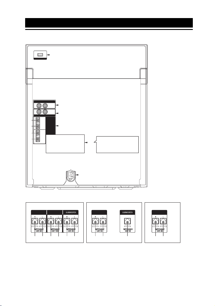
Hooking up the system securely
A
FM/ AM
ANTENNA
TV IN
AUDIO
R
L
D
IN
AUDIO
L
R
IN
FRONT
L
R
L
R
LED
SPEAKER
FRONT SPEAKERS
R
IMPEDANCE
USE 6Ω
E
(MHC-GTR888/
C
MHC-GTR777 only)
SATELLITE
SPEAKERS
L
R
L
IMPEDANCE
USE 12Ω
SUBWOOFER
R
IMPEDANCE
USE 8Ω
F
B
L
B is different
B
depending on the model.
See below.
DVD/PC IN
2
1
6
5
SUBWOOFER
1 To front speaker
(right)
2 To front speaker (left)
3 To satellite speaker
(right)
4 To satellite speaker
(left)
5 To subwoofer (right)
6 To subwoofer (left)
7 To subwoofer
B
MHC-GTR888/MHC-GTR777 MHC-GTR555 MHC-GTR333
FRONT SPEAKERS FRONT SPEAKERS FRONT SPEAKERS
GB
8
SATELLITE
SPEAKERS
1 2 3 4 5 6 1 2 7 1 2

A Antennas
Find a location and an orientation that
provide good reception, and then set up
the antennas.
Keep the antennas away from the speaker
cords, the power cord and the USB cable
to avoid picking up noise.
Extend the FM lead
antenna horizontally
AM loop antenna
B Speakers
The speaker connectors are color-coded
with their respective speaker terminals on
the unit.
Example:
White
Notes
• Be sure to use only the supplied speakers.
• When connecting speaker cords, insert the
connector straight into the terminals.
D TV IN L/R jacks
Use an audio cord (not supplied) to
connect to the audio output jacks of a TV.
The TV sound is output through this
system.
E DVD/PC IN L/R jacks
Use an audio cord (not supplied) to
connect to the audio output jacks of an
audio/video equipment. The audio is
output through this system.
F Power
Plug the power cord into a wall socket.
The demonstration appears in the display
panel. Press "/1 to turn on the system and
the demonstration automatically ends.
If the supplied adaptor on the plug does
not fit your wall outlet, detach it from the
plug (only for models equipped with an
adaptor).
Inserting batteries
Insert the two supplied R6 (size AA)
batteries, matching the polarities shown
below.
Getting Started
C LED SPEAKER terminals
Connect the LED SPEAKER connector of
the speaker to this terminal.
The lighting on the speakers will react
according to the music source. You can
select the lighting pattern according to
your preference (page 22).
Example:
Notes
• Do not mix an old battery with a new one or
mix different types of batteries.
• If you do not use the remote for a long period
of time, remove the batteries to avoid damage
from battery leakage and corrosion.
GB
9
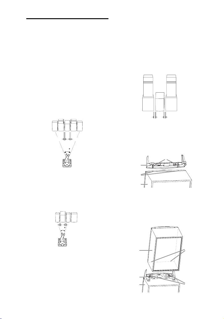
Positioning the speakers
To obtain optimum performance from the
system, we recommend you to place the
speakers as shown below.
A Unit
B Front speaker (left)
C Front speaker (right)
D Satellite speaker (left)
E Satellite speaker (right)
F Subwoofer (left)
G Subwoofer (right)
H Subwoofer
MHC-GTR888/MHC-GTR777 only
*
D*E
A
CB
FG
0.3 m 0.3 m
45
* (MHC-GTR888 only) Before you place the
satellite speaker on top of the subwoofer, be
sure to put the Spacer A on the subwoofer. See
step 1 of “Installing” (page 10) on how to
install the Spacer A.
MHC-GTR555/MHC-GTR333 only
C
A
*
B
0.3 m 0.3 m
H
45
Line Array Speaker System
(MHC-GTR888 only)
To create a party environment, we
recommend that you install your speakers
using Line Array Speaker System. Line
Array Speaker System provides a wide
sound space that suitable for large room
like a hall.
– Positioning
D
B
F
0.3 m 0.3 m
A
E
C
G
– Installing
1 Insert the pins of the Spacer A
(supplied) to the catcher holes on
top of the subwoofer.
Pin
Spacer A
Catcher hole
Subwoofer
2 Stack the front right speaker on top
of the subwoofer. Make sure the
catcher holes of the front right
speaker is inserted to the pins of the
Spacer A.
* MHC-GTR555 only.
GB
10
Front right
speaker
Spacer A
Subwoofer
Catcher
hole
Pin
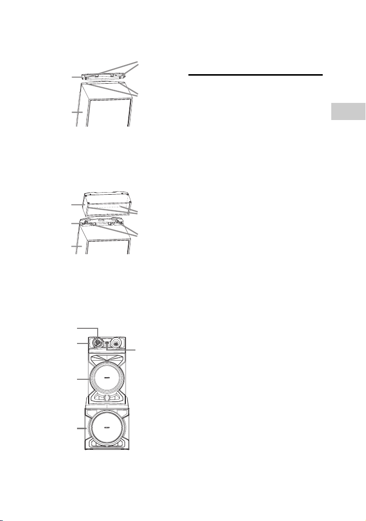
3 Insert the pins of the Spacer B
(supplied) to the catcher holes on
the front right speaker.
Spacer B
Front right
speaker
Pin
Catcher
hole
4 Stack the satellite right speaker on
the front right speaker. Make sure
the catcher holes of the satellite
right speaker is inserted to the pins
of the Spacer B.
Satellite
right
speaker
Spacer B
Front right
speaker
Catcher
hole
Pin
5 Check that the woofer of the
satellite right speaker is near to the
unit.
Turn the SONY emblem on the
satellite right speaker to horizontal
position.
Woofer
Satellite right
speaker
SONY
emblem
6 Repeat steps 1 to 5 to install
another subwoofer, front left
speaker and satellite left speaker.
Setting the clock
You cannot set the clock in Power Saving
Mode.
Use the buttons on the remote control to
perform this operation.
1 Press "/1 to turn on the system.
2 Press CLOCK/TIMER SET.
If “PLAY SET” appears in the display
panel, press ./> repeatedly to
select “CLOCK SET”, then press
ENTER.
3 Press ./> repeatedly to set
the hour, then press ENTER.
4 Press ./> repeatedly to set
the minutes, then press ENTER.
Getting Started
Front right
speaker
Subwoofer
11
GB
 Loading...