

Sony HCD-D60, HCD-GR7, HCD-GR7J, HCD-RX70 Service Manual

HCD-D60/GR7/GR7J/RX70
—
US Model
SERVICE MANUAL
HCD-D60/RX70
Ver 1.1 2002.11
HCD-D60/ GR7/GR7J/RX70 is the
tuner, deck, CD and amplifier section in
MHC-D60/ GR7/GR7J/RX70.
* Dolby noise reduction manufacrured
under license from Dolby Laboratories
Licensing corporation.
"DOLBY" and the double-D symbol a
are trademarks of Dolby Laboratories
Licensing Corporation.
Photo: HCD-RX70
CD
Section
Tape deck
Section
SPECIFICATIONS
Canadian Model
AEP Model
UK Model
HCD-RX70
E Model
HCD-GR7/GR7J
Australian Model
HCD-GR7
Model Name Using Similar Mechanism NEW
CD Mechanism Type
Base Unit Name BU-5BD29AL
Optical Pick-up Name
Model Name Using
Tape Transport Mechanism Type TCM-220WR2
Similar Mechanism HCD-H881
CDM38-5BD29AL
KSS-213D/Q-NP
For the US model
AUDIO POWER SPECIFICATIONS
POWER OUTPUT AND TOTAL
HARMONIC DISTORTION:
With 8 ohm loads, both channels driven, from
70-20,000 Hz; rated 100 watts per channel
minimum RMS power, with no more than
0.9% total harmonic distortion from 250
milliwatts to rated output.
Amplifier section
Continuous RMS power output
Canadian model
100+100 watts
(8 ohms at 1 kHz, 5% THD)
AEP, German, East European, UK and CIS models
55+55 watts
(6 ohms at 1 kHz, 10% THD)
Other models 70+70 watts
(6 ohm sat 1 kHz, 10% THD)
Peak music power output (GR7/GR7J) :
1000 watts
Music power output
(AEP, German, East European, UK and CIS model):
95+95 watts
(6 ohms at 1kHz, 10% THD)
Inputs VIDEO/MD IN (phono jacks) :
voltage 250 mV,impedance 47
kilo ohms
MIX MIC (phone jack):
sensitivity 1 mV,
impedance 10 kilo ohms
Outputs VIDEO/MD OUT (phono jacks)
: voltage 250 mV impedance
1 kilo ohms
PHONES (stereo phone jack) :
accepts headphones of 8 ohms or
more.
SPEAKER : accepts impedance of
8 to 16 ohms (D60/RX70)
accepts impedance of 6 to 16 ohms
(GR7/GR7J)
SURROUND SPEAKER
(US and Canadian models):
accepts impedance of 16 ohms.
SUPER WOOFER (GR7/GR7J/
RX70 : US and Canadian models):
V oltage 1 V, impedance 1 kilo ohm
CD player section
System Compact disc and digital audio
system
Laser Semiconductor laser
(λ=780nm)
Emission duration: continuous
Laser output Max. 44.6 µW*
*This output is the value measured at a distance of 200 mm
from the objective lens surface
on the Optical Pick-up Block
with 7 mm aperture.
Frequency response 2 Hz - 20 kHz (±0.5 dB)
Wavelength 780-790 nm
Signal-to-noise ratio More than 90 dB
Dynamic range More than 90 dB
CD OPTICAL DIGITAL OUT
(Square optical connector jack, rear panel)
(Except US model)
Wavelength 600 nm
Output Level –18 dBm
— Continued on next page
9-960-853-12 Sony Corporation
2002K0500-1 Home Audio Company
C 2002.11 Published by Sony Engineering Corporation
COMPACT DISC DECK RECEIVER
Tape player section
Recording system 4-track 2-channel stereo
Frequency response 60 - 13,000 Hz (±3 dB), using Sony TYPE I cassette
(DOLBY NR OFF) 60 - 14,000 Hz (±3 dB), using Sony TYPE II cassette
Wow and flutter ±0.15% W. Peak (IEC)
0.1% W .RMS (NAB)
±0.2% W .Peak (DIN)
Tuner section
FM stereo, FM/AM superheterodyne tuner
FM tuner section
Tuning range
East European and CIS models:
65.0 - 74.0 MHz
87.5 - 108.0 MHz
Other models 87.5 - 108,0 MHz
Antenna terminals 75 ohm unbalanced
Intermediate frequency 10.7 MHz
UKV tuner section (East European and CIS models)
Tuning range 65.0 - 74.0 MHz Polar stereo
AM tuner section
Tuning range
US and Canadian models:
530 - 1,710 kHz
(with the AM tuning interval set at 10kHz)
531 - 1,710 kHz
(with the AM tuning interval set at 9 kHz)
EA4, E2, Mexican, Australian and Thailand models:
531 - 1,602 kHz
(with the AM tuning interval set at 9 kHz)
530 - 1,710 kHz
(with the AM tuning interval set at 10 kHz)
AEP, German, East European, UK and CIS models:
MW 531 - 1,602 kHz
(with the MW tuning interval set at 9 kHz)
LW 153 -279 kHz
(with the LW tuning interval set at 3 kHz)
Other models: MW 531 - 1,602 kHz
(with the MW tuning interval set at 9 kHz)
530 - 1,710 kHz
(with the MW tuning interval set at 10 kHz)
SW 5.95 - 17.90 MHz
(with the SW tuning interval set at 5 kHz)
Intermediate frequency 450 kHz
Antenna AM loop antenna
External antenna terminal
General
Power requirements
US and Canadian models:
120 V AC, 60 Hz
Mexican model: 120 V AC, 50/60 Hz
AEP, German, East European, UK and CIS models:
220 - 230 V AC, 50/60 Hz
Australian and South African models:
220 - 240 V AC, 50/60 Hz
EA4 and Thailand model:
220 - 240 V AC, 50/60 Hz
Other models: 110 - 120 V or 220 - 240 V AC,
50/60 Hz Adjustable with voltage selector
Power consumption
US and Canadian models:
195 watts
AEP, German, East European, UK and CIS models:
115 watts
Other models: 135 watts
Dimensions (w/h/d) Approx. 280×330×366 mm
Mass Approx. 9.3 kg
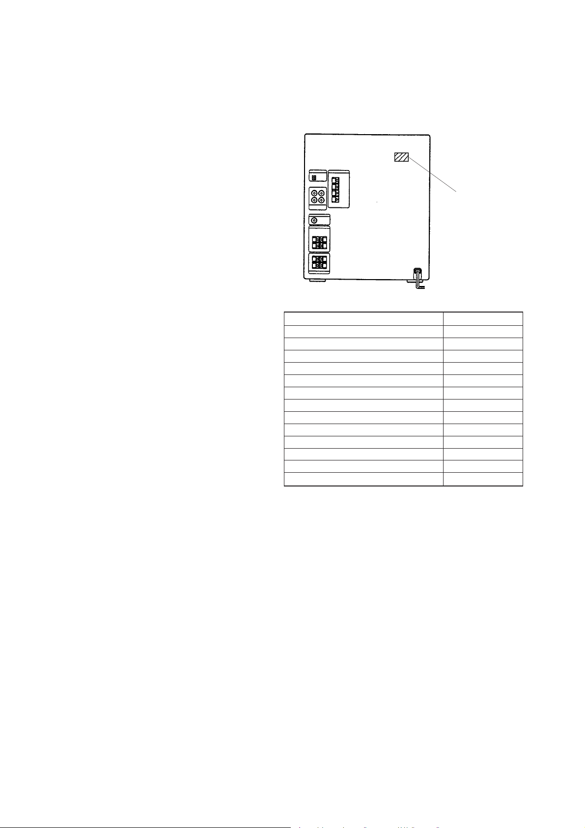
MEDEL IDENTIFICATION
– BACK PANEL –
PARTS No.
MODEL PARTS NO.
D60 : US model 4-986-844-7π
GR7 : E3 model 4-988-019-0π
GR7 : E2 model 4-988-019-1π
GR7 : MY, SP model 4-988-019-2π
GR7 : EA3, TW model/GR7J: EA3 model 4-988-019-3π
GR7 : HK model 4-988-019-4π
GR7 : AUS model 4-988-019-5π
GR7 : MX model 4-988-019-6π
GR7 : EA4, SAF, TH model 4-988-019-7π
RX70 : US model 4-986-844-0π
RX70 : CND model 4-986-844-1π
RX70 : AEP, AED, G, UK model 4-986-844-2π
RX70 : CIS, EE model 4-986-844-3π
• Abbreviation
AED : Northern European model
AUS : Australian
CND : Canadian
E2 : 120 V AC Area in E model
E3 : 240 V AC Area in E model
EA3 : Saudi Arabia
EA4 : Israeli
EE : East European
G : German
HK : Hong Kong
MX : Mexican
MY : Malaysia
SAF : South African
SP : Singapore
TH : Thailand
TW : Taiwan
Design and specifications are subject to change without notice.
– 2 –

CAUTION
Use of controls or adjustments or performance of
procedures other than those specified herein may
result in hazardous radiation exposure.
This appliance is classified as a CLASS 1 LASER product.
The CLASS 1 LASER PRODUCT MARKING is located on
the rear exterior.
Laser component in this product is capable of emitting radiation
exceeding the limit for Class 1.
The following caution label is located inside the unit.
SAFETY CHECK-OUT
After correcting the original service problem, perform the following safety check before releasing the set to the customer:
Check the antenna terminals, metal trim, “metallized” knobs, screws,
and all other exposed metal parts for AC leakage.
Check leakage as described below.
LEAKAGE TEST
The AC leakage from any exposed metal part to earth ground and
from all exposed metal parts to any exposed metal part having a
return to chassis, must not exceed 0.5 mA (500 microampers.). Leakage current can be measured by any one of three methods.
1. A commercial leakage tester, such as the Simpson 229 or RCA
WT-540A. Follow the manufacturers’ instructions to use these
instruments.
2. A battery-operated AC milliammeter. The Data Precision 245
digital multimeter is suitable for this job.
3. Measuring the voltage drop across a resistor by means of a V OM
or battery-operated A C voltmeter. The “limit” indication is 0.75
V, so analog meters must have an accurate low-voltage scale.
The Simpson 250 and Sanwa SH-63Trd are examples of a passive VOM that is suitable. Nearly all battery operated digital
multimeters that have a 2 V AC range are suitable. (See Fig. A)
To Exposed Metal
Parts on Set
SAFETY-RELATED COMPONENT WARNING!!
COMPONENTS IDENTIFIED BY MARK ! OR DOTTED
LINE WITH MARK ! ON THE SCHEMATIC DIAGRAMS
AND IN THE PARTS LIST ARE CRITICAL TO SAFE
OPERATION. REPLACE THESE COMPONENTS WITH
SONY PARTS WHOSE PART NUMBERS APPEAR AS
SHOWN IN THIS MANUAL OR IN SUPPLEMENTS PUBLISHED BY SONY.
AC
0.15 µF
1.5 k
Ω
Earth Ground
voltmeter
(0.75 V)
Fig. A. Using an AC voltmeter to check AC leakage.
ATTENTION AU COMPOSANT AYANT RAPPORT
À LA SÉCURITÉ!
LES COMPOSANTS IDENTIFIÉS P AR UNE MARQUE !
SUR LES DIAGRAMMES SCHÉMATIQUES ET LA LISTE
DES PIÈCES SONT CRITIQUES POUR LA SÉCURITÉ
DE FONCTIONNEMENT. NE REMPLACER CES COMPOSANTS QUE PAR DES PIÈCES SONY DONT LES
NUMÉROS SONT DONNÉS DANS CE MANUEL OU
DANS LES SUPPLÉMENTS PUBLIÉS PAR SONY.
– 3 –

TABLE OF CONTENTS
Servicing Notes ........................................................................... 4
1. GENERAL ..................................................................... 5
2. DISASSEMBLY .......................................................... 22
3. TEST MODE ............................................................... 28
4. MECHANICAL ADJUSTMENTS .......................... 30
SERVICING NOTES
NOTES ON HANDLING THE OPTICAL PICK-UP
BLOCK OR BASE UNIT
The laser diode in the optical pick-up block may suffer electrostatic
break-down because of the potential difference generated by the
charged electrostatic load, etc. on clothing and the human body.
During repair, pay attention to electrostatic break-down and also
use the procedure in the printed matter which is included in the
repair parts.
The flexible board is easily damaged and should be handled with
care.
5. ELECTRICAL ADJUSTMENTS
Deck Section...................................................................... 30
Tuner Section..................................................................... 33
CD Section......................................................................... 34
6. DIAGRAMS
6-1. Printed Wiring Board –Tuner Section– ............................. 37
6-2. Schematic Diagram –Tuner Section– ................................ 38
6-3. Printed Wiring Board –CD Section– ................................. 41
6-4. Schematic Diagram –CD Section– .................................... 43
6-5. Printed Wiring Boards –CD Motor Section–..................... 45
6-6. Schematic Diagram –CD Motor Section– ......................... 47
6-7. Printed Wiring Boards –Deck Section– ............................. 49
6-8. Schematic Diagram –Deck Section– ................................. 51
6-9. Schematic Diagram –Main /Power Section–..................... 55
6-10. Printed Wiring Boards –Main /Power Section–................. 59
6-11. Schematic Diagram –Panel Section–................................. 63
6-12. Printed Wiring Boards –Panel Section– ............................ 67
6-13. Printed Wiring Board –Power Amp Section–.................... 71
6-14. Schematic Diagram –Power Amp Section–....................... 72
6-15. IC Pin Function Description .............................................. 79
7. EXPLODED VIEWS .................................................. 83
8. ELECTRICAL PARTS LIST .................................... 93
NOTES ON LASER DIODE EMISSION CHECK
The laser beam on this model is concentrated so as to be focused on
the disc reflective surface by the objective lens in the optical pickup block. Therefore, when checking the laser diode emission, observe from more than 30 cm away from the objective lens.
Notes on chip component replacement
• Never reuse a disconnected chip component.
• Notice that the minus side of a tantalum capacitor may be dam-
aged by heat.
Flexible Circuit Board Repairing
• Keep the temperature of the soldering iron around 270 ˚C during
repairing.
• Do not touch the soldering iron on the same conductor of the
circuit board (within 3 times).
• Be careful not to apply force on the conductor when soldering or
unsoldering.
– 4 –
SECTION 1
GENERAL
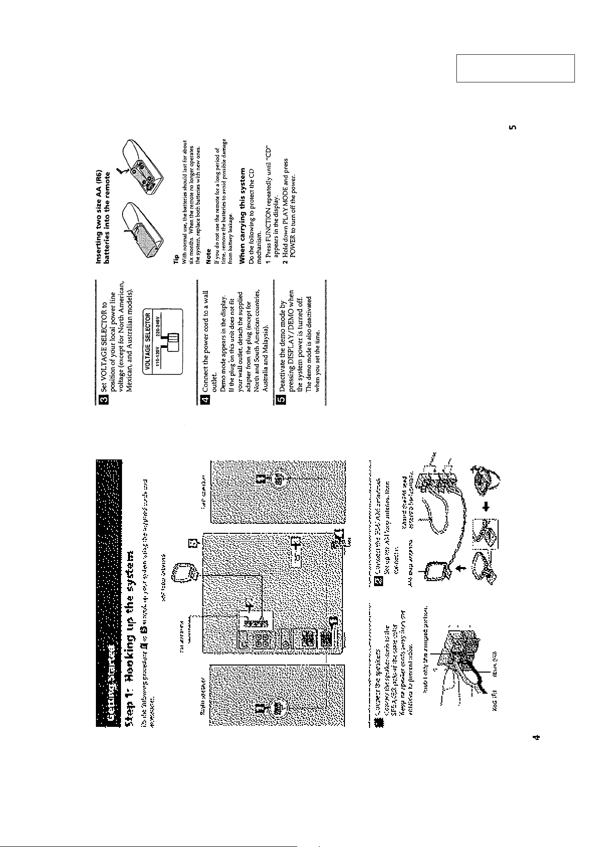
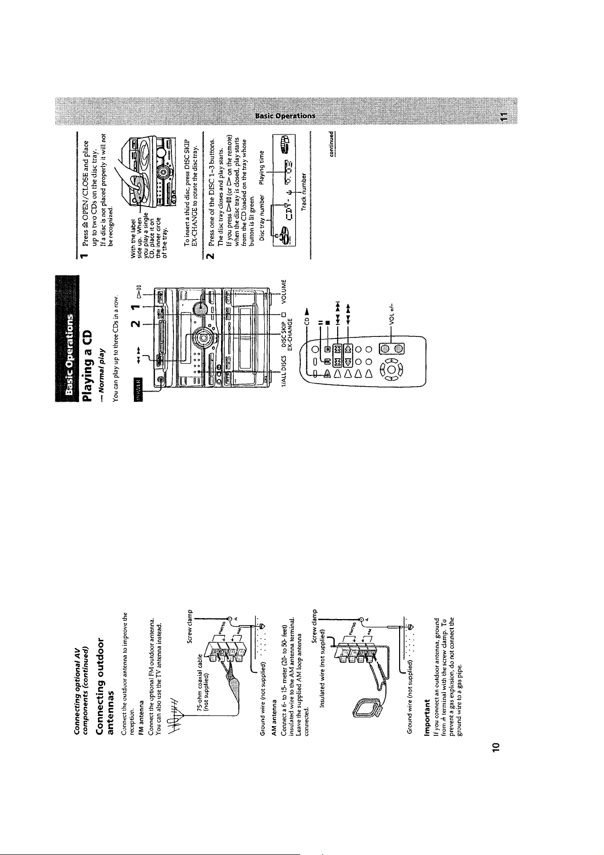
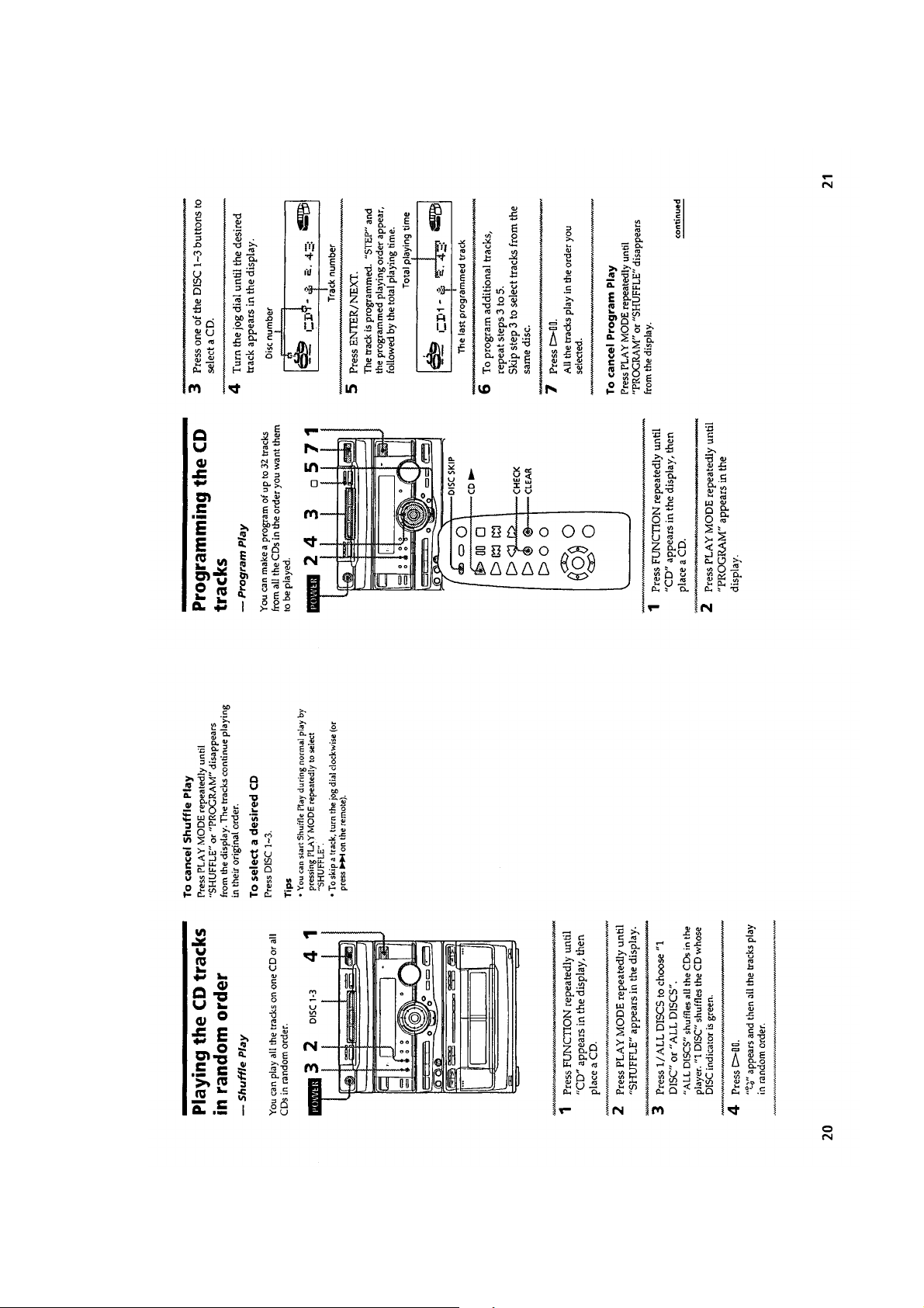
This section is extracted
from instruction manual.
– 5 –

– 6 –

– 7 –
– 8 –

– 9 –

– 10 –

– 11 –

– 12 –
– 13 –

– 14 –
– 15 –

– 16 –

– 17 –
– 18 –

– 19 –

– 20 –
– 21 –

• This set can be disassembled in the order shown below.
SECTION 2
DISASSEMBLY
CASE
(Page 22)
FRONT PANEL
SECTION
(Page 22)
CD MECHANISM
DECK SECTION
(Page 23)
TAPE MECHANISM
DECK SECTION
(Page 23)
Note: Follow the disassembly procedure in the numerical order given.
2
CASE
1
two screws
(case 3 TP2)
(3 × 8)
screw (case 3 TP2)
(3 × 10)
BASE UNIT
(Page 24)
MAIN BOARD
(Page 24)
TRAY SECTION
(Page 25)
MD BOARD
(Page 27)
BD BOARD
(Page 26)
CAPSTAN MOTOR
(Page 27)
3
three screws
(BVTT 3 × 6)
4
2
screw
(case 3 TP2)
(3 × 10)
OPTICAL
PICK-UP
(Page 26)
SLED
MOTOR
(Page 26)
Remove the case to
direction of the arrow.
FRONT PANEL SECTION
3
loading panel
5
screw
(BVTT 3 × 10)
2
Pull the tray
A
1
Turn the cam to
direction of the
arrow A.
1
two screws
(case 3 TP2)
(3 × 8)
8
front panel section
7
two claws
5
screw
(BVTT 3 × 10)
– 22 –
6
four screws
(BVTT 3 × 6)
4
three flat wires
(CN102, 205, 206)

CD MECHANISM DECK SECTION
4
CD mechanism deck section
Note: The CD mechanism deck will
fall if three screws are removed.
Support it by hand, then remove
three screws.
1
two connectors
(CN203, 204)
3
three screws
(BVTP 3 × 8)
2
flat wire
(CN202)
T APE MECHANISM DECK SECTION
2
Open the
cassette lids.
4
tape mechanism deck
section
3
three screws
(BVTP 3 × 8)
1
Push the two buttons.
– 23 –
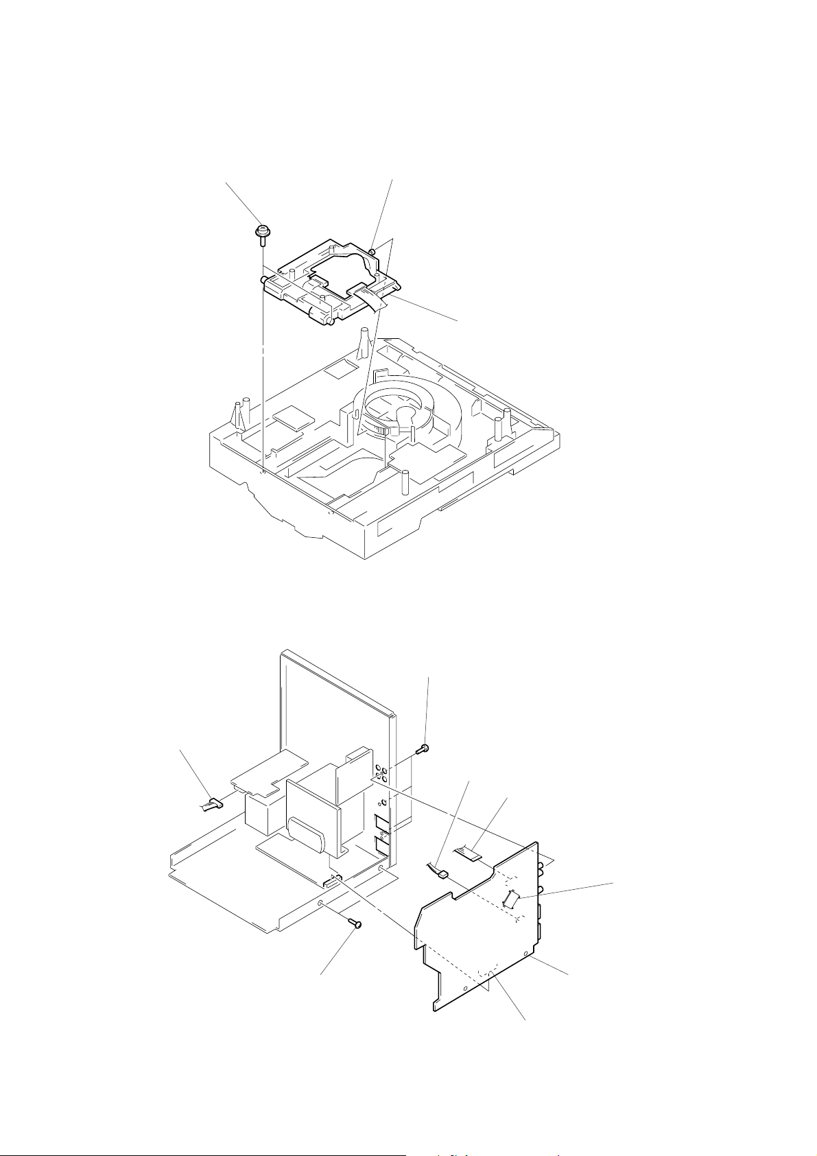
BASE UNIT
1
two yoke bracket
2
boss
3
base unit
MAIN BOARD
1
connector
(CN901)
4
two screws
(BVTP 3 × 8)
4
four screws
(BVTP 3 × 8)
2
connector
(CN105)
3
flat wire (CN201)
6
main board
IC201
– 24 –
5
connector
(CN101)
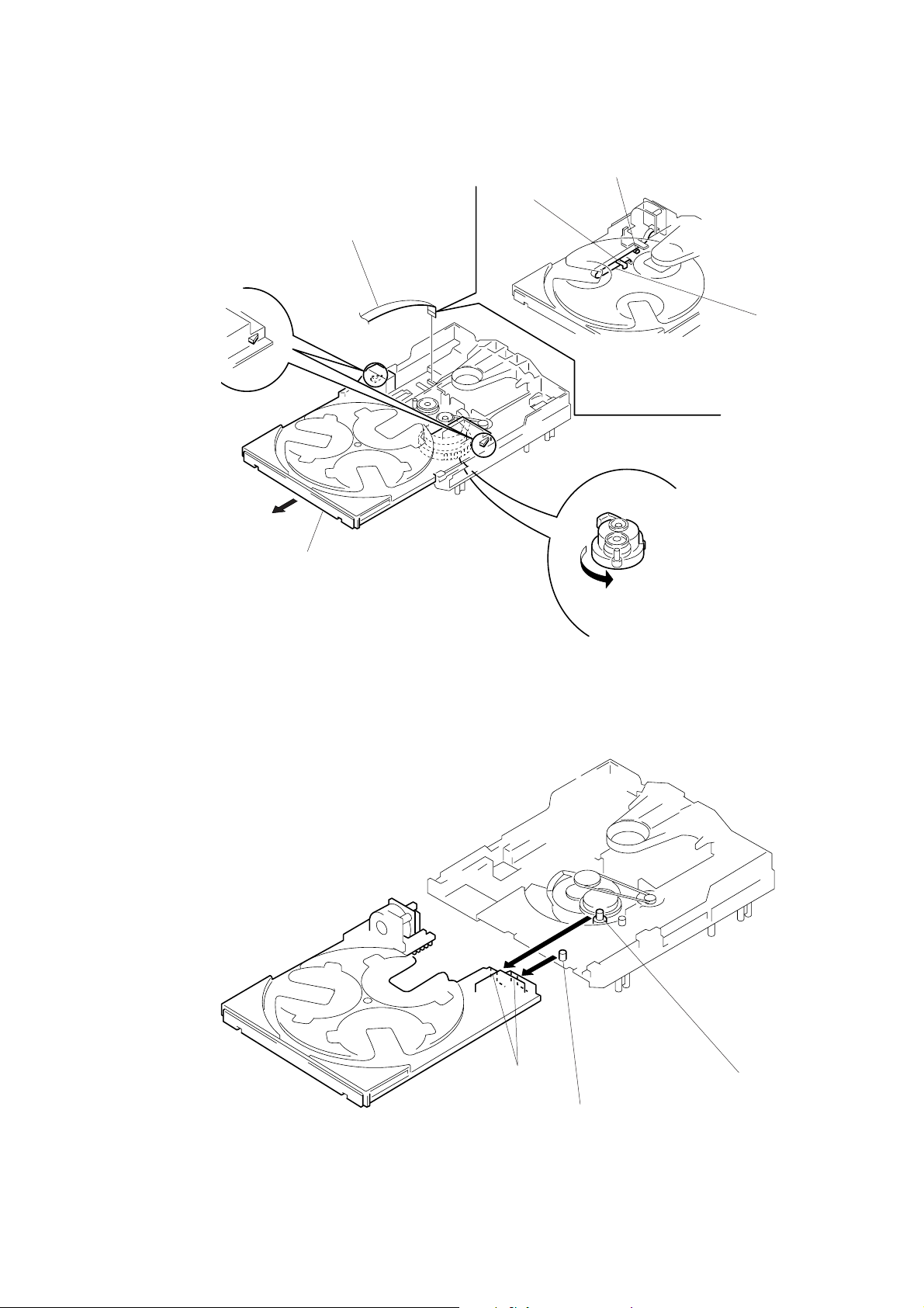
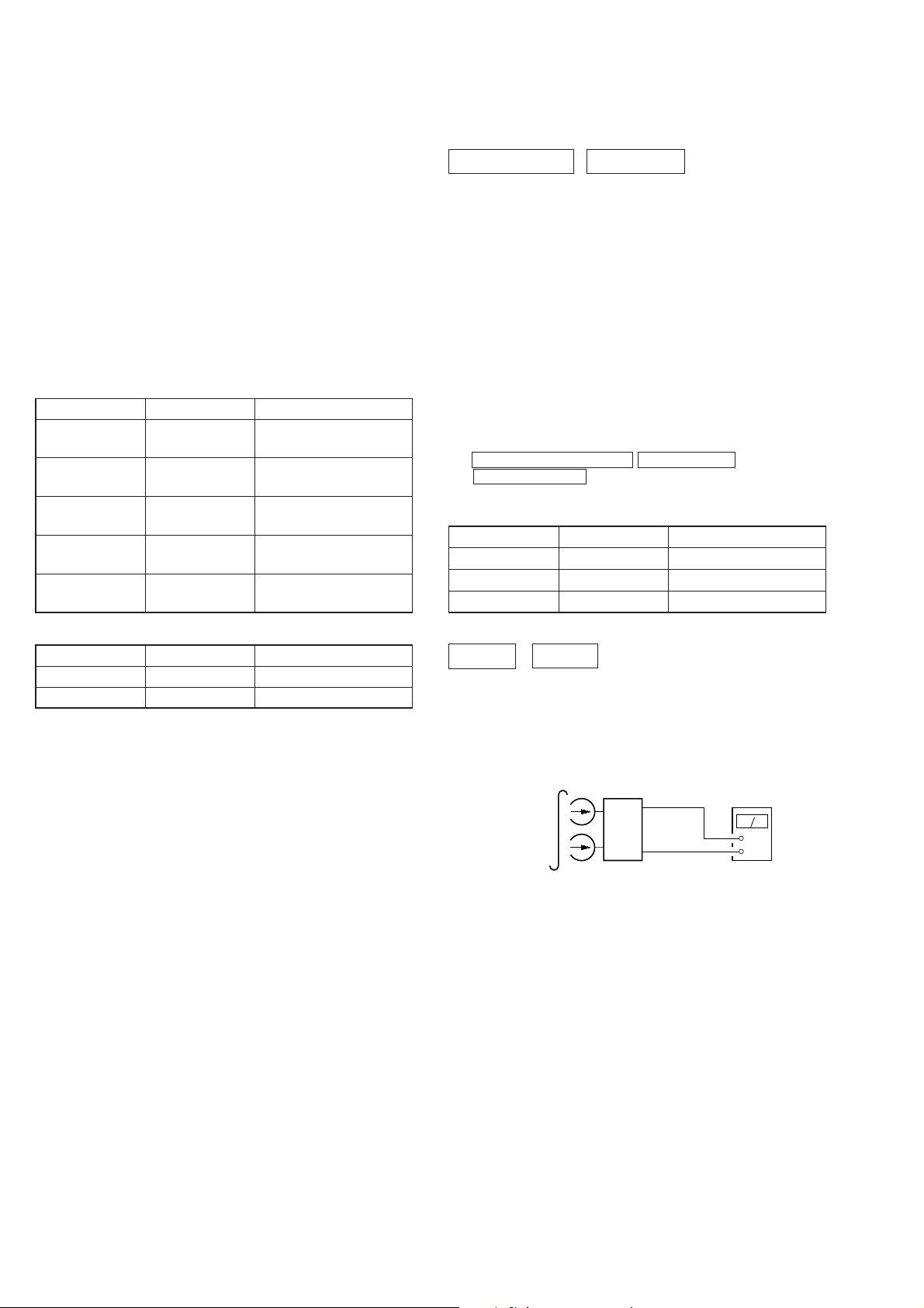
TRAY SECTION
3
flat wire
(CN705)
claw
B
claw
A
flat wire
4
two claws
2
Pull the tray.
5
Removal the tray.
Note: When installing the tray, take care so that the collars (A) and
(B) are properly inserted into the slots.
Note: When installing the tray, pull around the flat
wire to pass through the claw A and claw B,
as shown in the figure.
1
Turn the cam to direction
of the arrow.
– 25 –
slots
collar
B
collar
A

BD BOARD
1
two screws
(PTPWH M2.6 × 6)
3
5
screw
(BVTP 2.6 × 8)
two springs
6
Removal
the four solders.
1
two screws
(PTPWH M2.6 × 6)
2
optical pick-up
section
3
two springs
4
flat wire
(CN101)
7
BD board
limit switch
OPTICAL PICK-UP, SLED MOTOR
2
sled shaft
3
optical pick-up
1
claw
5
sled motor
4
two screws
(P 2 × 3)
– 26 –

MD BOARD
4
four screws
(BTP 2.6 × 4)
5
MD board
1
connector
(CN651)
2
two rivets
3
Break the soldering of two
flexible flat cables.
CAPSTAN MOTOR
1
Break the soldering of
motor lead.
4
Removal the capstan motor
to direction of the arrow.
3
claw
2
two screws
(BTP 2.6 × 8)
5
Hang the
two belts.
– 27 –

SECTION 3
TEST MODE
[MC Cold Reset]
• The cold reset clears all data including preset data stored in the
RAM to initial conditions. Execute this mode when returning the
set to the customer.
Procedure:
1. Press three buttons SPECTRUM ANALYZER ,
ENTER/NEXT , and DISC 1 simultaneously.
2. The fluorescent indicator tube becomes blank instantaneously,
and the set is reset.
[CD Delivery Mode]
• This mode moves the pickup to the position durable to vibration.
Use this mode when returning the set to the customer after repair.
Procedure:
1. Press POWER button to turn the set ON.
2. Press PLAY button and POWER button simultaneously.
3. A message “LOCK” is displayed on the fluorescent indicator
tube, and the CD delivery mode is set.
[MC Hot Reset]
• This mode resets the set with the preset data kept stored in the
memory. T he hot reset mode functions same as if the po wer cord
is plugged in and out.
Procedure:
1. Press three buttons SPECTRUM ANALYZER ,
ENTER/NEXT , and DISC 2 simultaneously.
2. The fluorescent indicator tube becomes blank instantaneously,
and the set is reset.
[Sled Servo Mode]
• This mode can run the CD sled motor freely. Use this mode, for
instance, when cleaning the pickup.
Procedure:
1. Select the function “CD”.
2. Press three buttons SPECTRUM ANALYZER ,
ENTER/NEXT , and FUNCTION simultaneously.
3. The Sled Servo mode is selected, if “CD” is blanking on the
fluorescent indicator tube.
4. With the CD in stop status, press ) button in CD section to
move the pickup to outside track, or 0 button to inside track.
5. To exit from this mode, perform as follows:
1) Move the pickup to the most inside track.
2) Press three buttons in the same manner as step 2.
Note:
• Always move the pickup to most inside track when exiting from
this mode. Otherwise, a disc will not be unloaded.
• Do not run the sled motor excessively, otherwise the gear can be
chipped.
[Change-over of AM Tuner Step between 9kHz and 10kHz]
• A step of AM channels can be changed over between 9kHz and
10kHz.
Procedure:
1. Press POWER button to turn the set ON.
2. Select the function “TUNER”, and press TUNER/BAND
button to select the BAND “AM”.
3. Press POWER button to turn the set OFF.
4. Press ENTER/NEXT and POWER buttons simultaneously,
and the display of fluorescent indicator tube changes to “AM
9k STEP” or “AM 10k STEP”, and thus the channel step is
changed over.
[LED and Fluorescent Indicator Tube All Lit, Key Check
Mode]
Procedure:
1. Press three buttons SPECTRUM ANALYZER ,
ENTER/NEXT , and DISC 3 simultaneously.
2. LEDs and fluorescent indicator tube are all turned on.
Press DISC 2 button, and the key check mode is activated.
3. In the key check mode, the fluorescent indicator tube displays
“K 1 V0 J0”. Each time a button is pr essed, “K”value increases.
However, once a button is pressed, it is no longer taken into
account.
“J” value increases like 1, 2, 3 ... if rotating JOG knob in “+”
direction, or it decreases like 0, 9, 8 ... if rotating in “–” direction.
“V” value increases like 1, 2, 3 ... if rotating VOLUME knob
in “+” direction, or it decreases like 0, 9, 8 ... if rotating in “–”
direction.
4. To exit from this mode, press three buttons in the same manner
as step 1, or disconnect the power cord.
[Change-over of FUNCTION Name]
• The FUNCTION name of external input terminal can be changed
over to VIDEO or MD.
Procedure:
1. Press POWER button to turn the set OFF.
2. Press POWER button together with FUNCTION button, and
the power is turned on, the display of fluorescent indicator tube
changes to “MD” or “VIDEO” instantaneously, and thus the
FUNCTION is changed over.
– 28 –

[Aging Mode]
This mode can be used for operation check of CD section and tape
deck section.
• If an error occurred:
The aging operation stops.
• If no error occurs:
The aging operation continues repeatedly.
1. Aging Mode in CD Section
1-1. Operating Method of Aging Mode
1. Set discs in DISC1 and DISC2 trays.
2. Select the function “CD”.
3. Press three buttons SPECTRUM ANALYZER ,
ENTER/NEXT , and KARAOKE PON/MPX simulta-
neously.
4. The aging mode is activated, if a roulette mark on the fluo-
rescent indicator tube is blinking.
5. In the aging mode, the aging is executed in a sequence giv en
in “1-2. Operation during Aging Mode”.
The aging continues unless an alarm occurred.
6. T o exit from the a ging mode, press POWER button to turn
the set OFF.
• If a button other than buttons In CD section is pressed during
aging, the aging in the CD section is finished.
• T o ex ecute aging to the tape deck section successiv ely, press ·
button in the deck A.
“ A GING” is displayed on the fluorescent indicator tube. (For the
aging in tape deck, see “2. Aging Mode in Tape Deck Section”.
1-2. Operation during aging Mode
In the aging mode, the program is executed in the following sequence.
1. The disc table is ejected.
2. The disc tray turns to select a disc. (For a disc selection
sequence, see Section 1-3.)
3. TOC of disc is read.
4. The pickup accesses to the last track.
5. A disc is ejected.
6. Steps 2 through 5 are repeated.
7. In the aging mode, the aging is executed in a sequence given
in “2-2. Operation during Aging Mode”.
The aging continues unless an alarm occurred.
8. To exit from the aging mode, press POWER button to turn
the set OFF.
2-2. Operation during Aging Mode
In the aging mode, the program is executed in the following sequence.
1. A tape on FWD side is played for one minute.
2. PAUSE STOP is made.
3. Recording is made for 3 minutes. (For the deck not having
the record function, the play is executed. In this case, ·
LED does not light up.)
4. FF is executed up to the end of tape.
5. A tape is reversed, and the tape on REV side is played for
one minute.
6. PAUSE STOP is made.
7. Recording is made for 3 minutes. (For the deck not having
the record function, the play is executed. In this case, ª
LED does not light up.)
8. FF is executed up to the end of tape.
9. Steps 1 through 8 are executed for the other deck.
10. Steps 1 through 9 are repeated unless an alarm occurred.
2-3. Deck Selection Sequence
• During the aging mode, decks are selected in the following se-
quence:
Deck A (FWD) → Deck A (REV)
↑↓
Deck B (REV) ← Deck B (FWD)
1-3. Disc Selection Sequence
• During the aging mode, discs are selected in the following se-
quence:
Disc 1 → Disc 2
↑↓
Disc 2 ← Disc 1
2. Aging Mode in Tape Deck Section
2-1. Operating Method of Aging Mode
1. Load a commercially available 10-minute tape into the decks
A and B respectively.
(If a 10-minute tape is not available, another tape may be
used but a cycle time will be longer.)
2. Select the function “TAPE”.
3. Rewind tapes in advance by pressing 0 button respectively on decks A and B.
4. Press three buttons SPECTRUM ANALYZER ,
ENTER/NEXT , and KARAOKE PON/MPX simulta-
neously.
5. Press · button on deck A. (This button triggers the aging mode.)
6. The aging mode is activated if “AGING A” is displayed on
the fluorescent indicator tube.
– 29 –
SECTION 4
MECHANISM ADJUSTMENTS
SECTION 5
ELECTRICAL ADJUSTMENTS
PRECAUTION
1. Clean the following parts with a denatured-alcohol-moistened
swab:
record/playback head pinch roller
erase head rubber belts
capstan idlers
2. Demagnetize the record/playback head with a head demagnetizer.
3. Do not use a magnetized screwdriver for the adjustments.
4. After the adjustments, apply suitable locking compound to the
parts adjusted.
5. The adjustments should be performed with the rated power supply voltage unless otherwise noted.
• Tor que Measurement
Mode Torque Meter Meter Reading
Forward CQ-102C
Forward
Back Tension (0.026 – 0.082 oz·inch)
Reverse CQ-102RC
Reverse
Back Tension (0.026 – 0.082 oz·inch)
FF, REW CQ-201B
CQ-102C
CQ-102RC
36 to 61g·cm
(0.50 – 0.84 oz·inch)
2 to 6g·cm
36 to 61g·cm
(0.50 – 0.84 oz·inch)
2 to 6g·cm
61 to 143g·cm
(0.85 – 1.98 oz·inch)
DECK SECTION 0dB=0.775V
1. Demagnetize the record/playback head with a head demagnetizer. (Do not bring the head demagnetizer close to the erase
head.)
2. Do not use a magnetized screwdriver for the adjustments.
3. After the adjustments, apply suitable locking compound to the
parts adjust.
4. The adjustments should be performed with the rated power supply voltage unless otherwise noted.
5. The adjustments should be performed in the order given in this
service manual. (As a general rule, playback circuit adjustment
should be completed before performing recording circuit adjustment.)
6. The adjustments should be performed for both L-CH and R-ch.
7. Switches and controls should be set as follows unless otherwise
specified.
8. Set to test mode. (Press key switch same time
SPECTRUM ANALYZER ENTER/NEXT and
EFFECT ON/OFF button.)
• T est Tape
Tape Signal Used for
P-4-A100 10kHz, –10 dB Azimuth Adjustment
WS-48B 3kHz, 0dB Tape Speed Adjustment
P-4-L300 315Hz 0dB Level Adjustment
• Tape T ension Measurement
Mode Tension Meter Meter Reading
Forward CQ-403A more than 100g (3.53 oz)
Reverse CQ-403R more than 100g (3.53 oz)
Record/Playback Head Azimuth Adjustment
DECK A DECK B
Note: Perform this adjustments for both decks
Procedure:
1. Mode: Playback (FWD)
test tape
P-4-A100
(10KHz, –10dB)
set
main board
CN207
Pin
1
(L-CH)
Pin
3
(R-CH)
main board
CN207
Pin
2
level meter
+
–
– 30 –
 Loading...