

Page 1

DSR-40/40P
3-865-349-16(1)
Digital
Videocassette
Recor der
Operating Instructions page 2
Before operating the unit, please read this manual
thoroughly and retain it for future reference.
Mode d’emploi page 2
Avant la mise en service de cet appareil, prière de lire
attentivement ce mode d’emploi que l’on conservera
pour toute référence ultérieure.
FR
GB
GB
FR
DSR-40/40P
1999 by Sony Corporation
Page 2

For DSR-40
WARNING
To prevent fire or shock hazard, do not
expose the unit to rain or moisture.
This symbol is intended to alert the user to the
presence of uninsulated “dangerous voltage”
within the product’s enclosure that may be of
sufficient magnitude to constitute a risk of
electric shock to persons.
This symbol is intended to alert the user to the
presence of important operating and
maintenance (servicing) instructions in the
literature accompanying the appliance.
CAUTION
Precautions
Safety
• Operate the unit only on 120 V AC, 60 Hz .
• If anything falls into the cabinet, unplug the unit and have it
checked by qualified personnel before operating it any
further.
• Unplug the unit from the wall outlet if you do not intend to
use it for an extended period of time. To disconnect the
cord, pull it out by the plug, never by the cord.
Installing
• Allow adequate air circulation to prevent internal heat
buildup.
• Do not place the unit on surfaces (rugs, blankets, etc.) or
near materials (curtains, draperies) that may block the
ventilation slots.
• Do not install the unit near heat sources such as radiators
or air ducts, or in a place subject to direct sunlight,
excessive dust, mechanical vibration or shock.
• Do not install the unit in an inclined position. It is designed
to be operated in a horizontal position only.
• The unit is not designed for portable use. Install it properly
on a flat stable place. Placing it on its side or on a surface
slanted more than 30 degrees may cause damage.
• Keep the unit and cassettes away from equipment with
strong magnets, such as microwave ovens or large
loudspeakers.
• Do not place heavy objects on the unit.
• If the unit is brought directly from a cold to a warm location,
moisture may condense inside the VCR and cause damage
to the video head and tape. When you first install the unit,
or when you move it from a cold to a warm location, wait for
about one hour before operating the unit.
You are cautioned that any changes or modifications not
expressly approved in this manual could void your authority
to operate this equipment.
Note
This equipment has been tested and found to comply with the
limits for a Class B digital device, pursuant to Part 15 of the
FCC Rules. These limits are designed to provide reasonable
protection against harmful interference in a residential
installation. This equipment generates, uses, and can radiate
radio frequency energy and, if not installed and used in
accordance with the instructions, may cause harmful
interference to radio communications. However, there is no
guarantee that interference will not occur in a particular
installation. If this equipment does cause harmful interference
to radio or television reception, which can be determined by
turning the equipment off and on, the user is encouraged to
try to correct the interference by one or more of the following
measures:
• Reorient or relocate the receiving antenna.
• Increase the separation between the equipment and
receiver.
• Connect the equipment into an outlet on a circuit different
from that to which the receiver is connected.
• Consult the dealer or an experienced radio/TV technician
for help.
Information
Compatible color systems
The DSR-40 is designed to record and play back using the
NTSC color system. Recording of video sources based on
other color systems cannot be guaranteed.
Caution
Television programs, films, video tapes and other materials
may be copyrighted. Unauthorized recording of such material
may be contrary to the provisions of the copyright laws. Also,
use of this recorder with cable television transmission may
require authorization from the cable television transmission
and/or program owner.
Owner’s record
The model number is located at the rear and front of the unit
and the serial number on the top. Record the serial number in
the space provided below. Refer to these numbers whenever
you call upon your Sony dealer regarding this product.
Model No. DSR-40 Serial No. ______________________
GB
2
Page 3

For the customers in the U.S.A.
Declaration of Conformity
Trade Name: SONY
Model No.: DSR-40
Responsible Party: Sony Electronics Inc.
Address: 680 Kinderkamack Road, Oradell,
NJ 07649 USA
Telephone No.: 201-930-6970
This device complies with Part 15 of the FCC Rules.
Operation is subject to the following two conditions: (1)
This device may not cause harmful interference, and (2)
this device must accept any interference received,
including interference that may cause undesired
operation.
For DSR-40P
WARNING
• The unit is not designed for portable use. Install it properly
on a flat stable place. Placing it on its side or on a surface
slanted more than 30 degrees may cause damage.
• Keep the unit and cassettes away from equipment with
strong magnets, such as microwave ovens or large
loudspeakers.
• Do not place heavy objects on the unit.
• Do not place any objects containing liquid (e.g. vases) on
the unit.
• If the unit is brought directly from a cold to a warm location,
moisture may condense inside the VCR and cause damage
to the video head and tape. When you first install the unit,
or when you move it from a cold to a warm location, wait for
one to two hours before operating the unit.
Caution
Television programmes, films, video tapes and other
materials may be copyrighted. Unauthorised recording of
such material may be contrary to the provisions of the
copyright laws. Also, use of this recorder with cable television
transmission may require authorisation from the cable
television transmitter and/or programme owner.
To prevent fire or shock hazard, do not expose the unit to
rain or moisture.
To avoid electrical shock, do not open the cabinet. Refer
servicing to qualified personnel only.
Precautions
Safety
• This unit operates on 220 – 240 V AC, 50 Hz. Check that
the unit’s operating voltage is identical with your local power
supply.
• If anything falls into the cabinet, unplug the unit and have it
checked by qualified personnel before operating it any
further.
• The unit is not disconnected from the mains as long as it is
connected to the mains outlet, even if the unit itself has
been turned off.
• Unplug the unit from the wall outlet if you do not intend to
use it for an extended period of time. To disconnect the
cord, pull it out by the plug, never by the cord.
• Do not use the unit in areas where there is danger of it
becoming wet.
Compatible colour systems
The DSR-40P is designed to record and play back using the
PAL colour system. Recording of video sources based on
other colour systems cannot be guaranteed.
For the customers in Europe
This product with the CE marking complies with both the
EMC Directive (89/336/EEC) and the Low Voltage Directive
(73/23/EEC) issued by the Commission of the European
Community.
Compliance with these directives implies conformity to the
following European standards:
• EN60065: Product Safety
• EN55103-1: Electromagnetic Interference (Emission)
• EN55103-2: Electromagnetic Susceptibility (Immunity)
This product is intended for use in the following
Electromagnetic Environment(s):
E1 (residential), E2 (commercial and light industrial), E3
(urban outdoors) and E4 (controlled EMC environment, ex.
TV studio).
Installing
• This unit is equipped with a fan at the rear. Do not insert
objects nor touch the fan during operation.
• To prevent internal heat buildup, install the unit at least
5 cm away from the wall, and dust the unit periodically.
• Do not place the unit on surfaces (rugs, blankets, etc.) or
near materials (curtains, draperies) that may block the
ventilation slots.
• Do not install the unit near heat sources such as radiators
or air ducts, or in a place subject to direct sunlight,
excessive dust, mechanical vibration or shock.
3
GB
Page 4

Table of Contents
Chapter 1
Overview
Chapter 2
Playback and
Recording
Features .............................................................................6
Notes on Video Cassettes .................................................... 8
Notes on Recording / Playing.............................................. 9
Location and Function of Parts .....................................10
Front Panel ........................................................................ 10
Rear Panel ......................................................................... 14
Playback...........................................................................16
Connections for Playback.................................................. 16
Settings for Playback......................................................... 18
Playback Procedure ........................................................... 19
Playback Functions ........................................................... 20
Recording ........................................................................23
Connections for Recording................................................ 23
Settings for Recording....................................................... 25
Recording Procedure ......................................................... 27
Chapter 3
Using the Unit as a
Player in an
Editing System
Chapter 4
Using the Unit as a
Recorder in an
Editing System
Notes on Usage in the Editing System .........................30
Connections for a Digital Non-linear Editing................32
Connections for a Cut Editing System..........................33
Connections for an A/B Roll Editing System ...............35
Adjusting an Edit Timing ................................................40
Adjusting the Sync and Subcarrier Phases..................44
Adjusting Signals............................................................47
Using the Unit as a Recorder
with FXE-100/100P/120/120P.................................49
GB
4
Table of Contents
Page 5

Chapter 5
Menu Settings
Chapter 6
Maintenance and
Troubleshooting
Appendix
Changing Menu Settings ................................................51
Changing the SET UP MENU Settings............................. 51
Menu Contents .................................................................. 51
Recommended settings in the SET UP menu.................... 54
Alarm Messages..............................................................55
Troubleshooting ..............................................................56
Notes on Use ...................................................................57
Specifications..................................................................60
Compatibility of DVCAM and DV Format ......................62
Glossary...........................................................................64
Index.................................................................................66
GB
Table of Contents 5
GB
Page 6

Features
Features
The DSR-40/40P is a 1/4-inch digital videocassette
recorder that uses the DVCAM digital recording
format. This system achieves stable, superb picture
quality by digitally processing video signals that are
separated into color difference signals and luminance
Chapter 1 Overview
signals (component video).
When connected to Sony Edit Station™, the unit
serves as part of powerful non-linear editing system
The unit is equipped with a full-fledged analog
interface to support hybrid systems that combine
conventional analog equipment with digital equipment.
The DSR-40/40P’s main features are described below.
DVCAM Format
DVCAM is based on the consumer DV format, which
uses the 4:1:1 component digital format (DSR-40) or
the 4:2:0 format (DSR-40P), and provides a
digital recording format for professional use.
High picture quality, high stability
Video signals are separated into color difference
signals and luminance signals, which are encoded and
compressed to one-fifth size before being recorded to
ensure stable and superb picture quality.
Because the recording is digital, multi-generation
dubbing can be performed with virtually no
deterioration of quality.
1
/4-inch
High-quality PCM digital audio
PCM recording makes for a wide dynamic range and a
high signal-to-noise ratio, thereby enhancing sound
quality.
There are two recording modes: 2-channel mode
1)
.
(48-kHz sampling and 16-bits linear code), which
offers sound quality equivalent to the DAT (Digital
Audio Tape) format, or 4-channel mode (32-kHz
sampling and 12-bits nonlinear code).
Playback compatibility with DV format
A DV cassette recorded on a DV-format VCR can be
played back on this unit. (Cassettes recorded in LP
mode cannot be played back.)
Choice of two cassette sizes
The unit can use both standard-size and mini-size
DVCAM cassettes.
•According to cassette size, it automatically changes
the position of the reel drive plate.
•The maximum recording/playback times are
184 minutes for standard size cassettes and 40
minutes for mini-size cassettes.
Facilities for High-efficiency
Editing
Wide track pitch
The unit provides an abundance of functions that
enhance editing efficiency and precision.
The recording track pitch is 15 µm, fully 50 percent
wider than the DV format’s 10-µm track pitch. Thanks
Remote control
to this feature, the DVCAM format sufficiently meets
the reliability and precision requirements of
professional editing.
The unit can be operated by remote control from an
editing controller that supports the RS-422A interface
2)
or from a SIRCS
-system remote control unit such as
the optional DSRM-10, or DSRM-20.
........................................................................................................................................................................................................
1) Non-linear editing
This is an editing method that uses video and audio
signals that have been digitally encoded and recorded on
a hard disk as digital data. When compared with
conventional (linear) editing methods, non-linear editing
offers vastly improved efficiency in editing operations,
such as by eliminating tape transport time.
GB
6
Chapter 1 Overview
2) SIRCS (Sony Integrated Remote Control System)
A command protocol to remote control Sony
professional videocassette recorders/players.
Page 7

Chapter 1 Overview
High-speed search function
If you use the optional remote control unit, the unit has
a picture search function that allows you to view color
picture at playback speeds up to 14 times normal speed
(DSR-40) or 17 times normal speed (DSR-40P) in
forward and reverse directions.
When remote-controlling this unit in shuttle mode
from an editing controller or a remote controller, you
can search at any speed in the range 0 (still) to 14
times normal (DSR-40) or 17 times normal (DSR-40P)
in both directions. You can also search frame-byframe in jog mode.
You can also hear playback audio.
Jog audio function
If you use the optional remote control unit, audio can
be monitored at various playback speeds when in jog
mode. The audio signals are once stored in memory
and then played back at the same rate as the search
speed. This allows you to use audio playback to find
the desired edit points.
Compact size
The unit achieves compact size suitable for using on a
demonstration or a bridal. The unit is also equipped
with basic functions that are needed for videocassette
recorders and players used in professional digital video
editing systems.
Menu system for functionality and
operation settings
The unit provides a menu system to make its various
functions easier to use and set up its operation
conditions.
Superimposition function
Time code, operation mode indications, menus, alarm
messages, and other text data can be superimposed and
output in analog composite video signals.
Easy maintenance function
Chapter 1 Overview
Other Features
Analog output interfaces
The unit comes with analog output interfaces enabling
it to be connected to analog video and audio
equipment.
•Analog video: Include composite video, component
video (Y/R–Y/B–Y), and S-video outputs.
•Analog audio: The XLR-type (3-pin) analog audio
outputs are provided.
“Power-on playback” function (in repeat
playback mode)
You can start playback immediately when the unit
turns on.
The unit’s digital hours meter functions include two
kinds of tally operations for head drum usage hours,
and tape threading/unthreading times. The tally results
can be viewed on the video monitor.
Chapter 1 Overview 7
GB
Page 8

Features
Notes on Video Cassettes
Usable cassettes
Chapter 1 Overview
Use Standard-DVCAM cassettes or Mini-DVCAM cassettes with this
VCR. PDV-184ME can record programs for 184 minutes and PDVM40ME can record for 40 minutes.
You can get the highest quality pictures with this digital videocassette
recorder using DVCAM cassettes. You may not be able to get as good
quality with other cassettes. We recommend using DVCAM cassettes so
that you can record your one-time events in highest quality.
Cassette memory
To save a recording
DVCAM cassette Mini DVCAM
cassette
Cassette memory is an optional feature that is mounted on some Standard
DVCAM cassettes and Mini DVCAM cassettes. When you record a
program, the recording date and time, and the programs’ position on the
tape are stored in the cassette memory so that you can quickly locate the
program later on.
indicates that you can use the cassettes 16 Kbits
of data can be stored on. On this VCR, you can use the cassettes up to
16 Kbits of data can be mounted on.
To prevent accidental erasure of a recording, slide in the safety switch on
the cassette so that the red portion becomes visible. To record on a tape,
slide out the switch so that the red portion is hidden.
Write protected
Write enabled
GB
8
Chapter 1 Overview
Note
, , and are trademarks.
Page 9

Checking the tape for slack
Notes on Recording / Playing
Copyright precautions
Using a paper clip or a similar object, turn the reel gently in the direction
shown by the arrow. If the reel does not move, there is no slack. Insert the
cassette into the cassette compartment, and after about 10 seconds take it
out.
Paper clip, etc.
Reel
On recording
You cannot record any software having copyright protection signals on this
VCR. If you start recording protected video and audio signals, a warning
message appears on the monitor screen and the VCR stops recording.
Chapter 1 Overview
On playback
When you play back software having copyright protection signals on this
VCR, you may not be able to copy it onto other equipment.
Limitations caused by the difference in format
This VCR can record, play back and edit the tapes recorded in DVCAM
format. It can also play back the tapes recorded in DV format (SP mode).
However, due to the difference in format, you may not be able to record or
edit some tapes affected by recording conditions of the tape (e.g., A tape
originally recorded in DV format is dubbed in DVCAM format). For
details, refer to “Compatibility of DVCAM and DV format” on page 62.
No compensation for contents of the recording
Contents of the recording cannot be compensated for if recording or
playback is not made due to a malfunction of the VCR, video tape, etc.
Note
You cannot play back a DVCAM tape recorded in other color systems on
this VCR.
Chapter 1 Overview 9
GB
Page 10
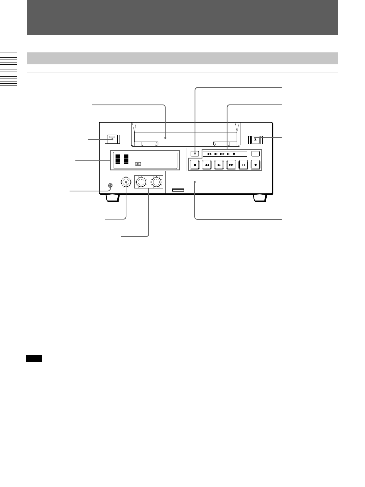
Location and Function of Parts
Location and Function of Parts
Front Panel
Chapter 1 Overview
1 Cassette compartment
2 ON/STANDBY switch
and ON/STANDBY lamp
1 Display section
(see page 11)
3 PHONES jack
4 PHONE LEVEL control knob
5 AUDIO INPUT LEVEL control knobs
INPUT
SELECT
COUNTER
TAPE
REMAIN
COUNTER
SELECT
TC
MONITOR
CH-1/2
MIX
CH-3/4
AUDIO
REPEAT
6 COUNTER RESET
button
2 Tape transport
control section
(see page 12)
7 EJECT button
DUP
TIMER
REMOTE
OFF
REC
LOCAL
MENU
SET
3 Inside of the door
(see page 13)
1 Cassette compartment
Accepts standard-size or mini-size DVCAM digital
videocassettes. When using a mini-size cassette, insert
it into the center of the compartment.
For details of usable cassettes, see page 8.
2 ON/STANDBY switch and ON/STANDBY lamp
Press this switch to turn on the power, and the ON/
STANDBY lamp lights in green. Press it again to turn
to standby mode, and the lamp lights in red.
Note
When the REMOTE/LOCAL switch is set to
REMOTE, you cannot turn the unit to standby mode.
3 PHONES jack (stereo minijack)
Connect stereo headphones for headphone monitoring
during recording or playback.
The audio signal you want to monitor can be selected
with the AUDIO MONITOR selector inside of the
door (3).
4 PHONE LEVEL control knob
Controls the volume of the headphones connected to
the PHONES jack.
5 AUDIO INPUT LEVEL control knobs
When recording, you can use these knobs to set audio
input levels for CH-1 (channel 1) and CH-2 (channel
2), respectively.
6 COUNTER RESET button
Press this button to reset the tape counter in the display
window to “0:00:00 (0
H00M00S)”. This button does not
work when displaying the time code or the remaining
time.
7 EJECT button
Press this button to eject a cassette.
10
GB
Chapter 1 Overview
Page 11

1 Display section
1 Audio level meter
0
6
9 Mini indicator
8 Cassette indicator
7 DVCAM indicator
12
24
–
CH 1/3 CH 2/4
HOURS MINUTES SECONDS FRAMES
Mini
1 Audio level meter
Indicates the recording level during recording or EE
mode, and the playback level during playback. When
the audio level exceeds 0 dB, the red indicator lights.
Note
If you play back the tape whose audio was only
recorded on channel 2, the audio level meter for CH2/4
may not function.
2 Time counter display
Indicates the following:
•Time data: count value of the time counter, time code
and remaining time.
•Alarm messages (see page 55).
•Messages for self-diagnosis function (see page 59).
Notes
•For DSR-40P: Time code is set to the non drop frame
mode only.
•Time code is indicated as follows:
Drop frame: “00:00.00:00” (DSR-40 only)
Non drop frame: “00:00:00:00”
3 Video input signals indicators
Indicates the currently selected video input signals.
INPUT VIDEO, INPUT S VIDEO, or INPUT DV
lights.
4 NS (Non Standard) AUDIO indicator
Lights when the VCR plays back a tape whose audio
recording was made in the unlock mode, or when unlock
mode signals are input through the DV jack.
For details of unlock mode, see page 62.
2 Time counter display
TIMER INPUT DV
NS AUDIO
Fs32k Fs48k
S VIDEO
3 Video input signals
indicators
4 NS AUDIO indicator
5 Audio mode indicators
6 TIMER indicator
5 Audio mode indicators
Indicates the audio mode during playback or recording
or while in EE mode.
•During playback it indicates the audio mode in which
the tape was recorded.
•During recording or while in EE mode, it indicates
the currently selected audio recording mode. You can
select audio recording mode by setting “AUDIO
MODE” menu (see page 53).
Fs32k: Lights when playing the tapes recorded in
4-channel mode, or recording a tape in 4-channel
mode.
Fs48k: Lights when playing the tapes recorded in
2-channel mode, or recording a tape in 2-channel
mode.
Note
When recording in 4-channel mode on this VCR, audio
signals are recorded only in channels 1/2.
6 TIMER indicator
Lights when setting the TIMER switch to REPEAT.
7 DVCAM indicator
Lights except playing back the DV-formatted tapes.
8 Cassette indicator
Lights when inserting a digital video cassette available
for this VCR. It flashes when ejecting a cassette.
9 Mini indicator
Lights when inserting mini-size digital video cassette.
Chapter 1 Overview
Chapter 1 Overview 11
GB
Page 12

Location and Function of Parts
2 Tape transport control section
Note
When the tape reaches to its beginning or its end by
rewinding or fast-forwarding, the unit turns to
Chapter 1 Overview
playback pause mode. Then, the playback pause mode
is released after the time which is set at “STILL
TIMER” menu (See page 52).
2 DUP button
1 Tape Transport indicators
STOP REW PLAY F FWD PAUSE REC
6 PLAY button
7 REW button
8 STOP button
1 Tape Transport indicators
2 DUP (duplicate) button
Use this button to make a work tape having the same
time codes as the source tape.
For details on duplication, see page 28.
3 REC (record) button
When you press the PLAY button while holding down
this button, the indicator lights and recording begins.
To set the VCR to recording pause mode, press the
PAUSE button while holding down this button.
4 PAUSE button
When you press this button, the indicator lights, and
the VCR is set to pause mode.
5 F FWD (fast forward) button
When you press this button, the indicator lights and the
tape is fast forwarded. During fast forward, the picture
does not appear on the monitor (you can see the
picture of the EE mode during fast forward).
To search forward, hold this button down during fast
forward.
DUP
4 PAUSE button
5 F FWD button
DUP
3 REC button
6 PLAY button
When you press this button, the indicator lights and
playback begins.
If you press this button while holding down the REW
button during stop, the tape is rewound to its beginning
and starts playing automatically (during rewind, the
REW indicator lights and the PLAY indicator flashes).
7 REW (rewind) button
When you press this button, the indicator lights and the
tape starts rewinding. During rewind, the picture does
not appear on the monitor (you can see the picture of
the EE mode during rewind).
To search backward, hold this button down during
rewind.
If you press the PLAY button while holding down this
button during stop, the tape is rewound to its beginning
and starts playing automatically (during rewind, the
REW indicator lights and the PLAY indicator flashes).
8 STOP button
Press this button to stop the current tape transport
operation.
12
GB
Chapter 1 Overview
Page 13

3 Inside of the door
6 REMOTE/LOCAL switch
COUNTER
INPUT
SELECT
1 INPUT SELECT button
SELECT
TC
COUNTER
TAPE
REMAIN
CL
2 CL button
3 COUNTER SELECT selector
AUDIO
MONITOR
CH-1/2
MIX
CH-3/4
REPEAT
4 AUDIO MONITOR selector
1 INPUT SELECT button
Selects input signals. Each press of this button cycles
through three video signal selection options: video, Svideo, and DV input. When you select one of these
options, the corresponding indicator in the display
lights up.
2 CL (Clear) button
Press this button to make the unit to the state of
reconnecting the AC power cord. When you press this
button, the setting in the menu is not initialized.
3 COUNTER SELECT selector
Select the type of time data in the time counter display.
TC: Time code
COUNTER: Count value of the time counter
TAPE REMAIN: Remaining time
4 AUDIO MONITOR selector
Use to select the audio track you want to hear when
playing back a tape recorded in 4-channel mode
(Fs32k).
CH-1/2: Channels 1/2 only
MIX: Channels 1/2 and channels 3/4 (mix)
CH-3/4: Channels 3/4 only
7 MENU button
8 SET button
9 Arrow (˘ ≥) buttons
TIMER
OFF
REMOTE
MENU
LOCAL
SET
5 TIMER switch
5 TIMER switch
Use to select Auto Repeat using an external AC timer
(not supplied).
REPEAT: When the power is supplied to this VCR,
a tape rewinds to its beginning automatically and
playback starts. The VCR repeats the playback
from the beginning to the first index (if there is no
index on the tape, to the unrecorded portion; if no
unrecorded portion, to the tape end). Auto repeat
also functions if you set this switch to REPEAT
during playback.
OFF: Auto Repeat is released.
6 REMOTE/LOCAL switch
Selects whether the unit is operated from its front
panel or from external (remote) equipment.
REMOTE : The unit is operated from an editing
controller connected to the REMOTE connector.
Available tape transport buttons (on the front
panel or optional remote control unit) are set in
the menu.
LOCAL : The unit is operated from its front panel,
or from a SIRCS-system remote control unit
connected to the CONTROL S jack.
Chapter 1 Overview
Chapter 1 Overview 13
GB
Page 14

Location and Function of Parts
7 MENU button
Press this button to display the menu on the monitor
screen. Press it again to return from the menu display
to the usual display.
Chapter 1 Overview
Note
If you set the REMOTE/LOCAL switch to REMOTE
while the menu display is on the monitor, it returns to
the usual display.
On how to use the menu, see Chapter 5 “Menu Settings”.
Rear Panel
S VIDEO
VIDEO
AUDIO
INPUT OUTPUT
CH-1
CH-1/3
CH-2
CH-2/4
REF.VIDEO INPUT
VIDEO
Y
R-Y B-Y
AUDIO CH-1/3 AUDIO CH-2/4
CONTROL S
8 SET button
Press this button to save selected menu items to the
unit’s memory.
9 Arrow (J j) buttons
Use these buttons to move around the menu items.
4 REF. VIDEO INPUT connector
5 CONTROL S jack
DV
REMOTE
RS-422A
IN/OUT
AC IN
6 REMOTE connector
7 DV jack
8 AC IN connector
MONITOR
3 OUTPUT connectors
2 MONITOR connectors
1 INPUT connectors
1 INPUT connectors
Input video and audio signals. To connect a VCR
equipped with the S-video output jack, use the
S VIDEO jack on this VCR.
2 MONITOR connectors
Output video and audio signals for monitoring.
3 OUTPUT connectors
Output video and audio signals. To connect a VCR
equipped with the S-video input jack, use the S
VIDEO jack on this VCR. To connect a VCR
equipped with the component input connectors, use the
Y, R–Y, B–Y connectors on this VCR.
14
GB
Chapter 1 Overview
Page 15

Note on EE mode
When the S-video, video, or DV signal is input, this
VCR cannot output component signals. You can only
output the component signal during normal playback.
4 REF. VIDEO INPUT connector (BNC-type)
Input a reference video (black burst) signal.
5 CONTROL S jack
When controlling this VCR from an optional remote
control unit such as the DSRM-10/20 (not supplied),
connect the unit to this jack.
Note
SIRCS-system has the same function as
CONTROL S-system.
6 REMOTE connector (D-sub 9-pin)
Connect an editing controller with the RS-422A
interface for remote-control of this VCR.
7 DV jack
The DV jack is i.LINK compatible. Use when the
equipment connected to the VCR has a DV jack.
If you connect the VCR and the other equipment using
DV jacks, you can minimize deterioration of picture
quality during dubbing, or capturing still pictures by
digital processing. For details, refer to the instruction
manual of the equipment you use.
Chapter 1 Overview
Note
is a trademark of Sony Corporation and indicates
that this product is in agreement with IEEE1394-1995
specifications and their revisions.
8 AC IN connector
Connect to an AC power outlet using the supplied
power cord.
Chapter 1 Overview 15
GB
Page 16

Playback
Playback
This section describes the necessary connections, settings and operations
to perform playback on this unit. The same settings and operations apply
whether you are using the unit as part of an editing system, for dubbing, or
as a stand-alone videocassette player.
Connections for Playback
To digital video equipment with the DV jack
Chapter 2 Playback and Recording
The video and audio signals are sent with hardly any degradation, enabling
high-quality recording. The signal flow is automatically detected so you
need not make separate connections for input and output.
Recorder
to the DV
jack
Monitor
i.LINK cable (DV connecting cable)
(not supplied)
This VCR (Player)
DV
IN/OUT
L: Signal flow
16
GB
Chapter 2 Playback and Recording
Notes
•The external lock function of this unit only supports the standard sync
signals. With the DV connection, select the DV input with the INPUT
SELECT button on this VCR to prevent malfunction resulting from
noise, etc.
•Set DV EE OUT in the menu to OFF (see page 52).
•With the DV connection, the sound is recorded in the same audio
recording mode as that of the source tape.
•With the DV connection, tape information (recording date, camcorder
data, etc.) recorded on the source tape is transmitted from this VCR
(player).
Page 17

To video equipment without the DV jack
Chapter 2 Playback and Recording
Recorder
Monitor
INPUT OUTPUT
S VIDEO
S VIDEO
VIDEO
VIDEO
AUDIO
AUDIO
INPUT OUTPUT
CH-1
CH-1/3
CH-1
CH-1/3
CH-2
CH-2/4
CH-2
CH-2/4
MONITOR
MONITOR
to the S-video
input jack
to the video
input jack
to the audio
input jacks
to the video
input jacks
S-video cable (not supplied)
75 Ω coaxial cable (not supplied)
XLR cable (not supplied)
Video cable (3BNCy3BNC) (not supplied)
This VCR (Player)
REF.VIDEO INPUT
REF.VIDEO INPUT
VIDEO
VIDEO
Y
R-Y B-Y
Y
R-Y B-Y
AUDIO CH-1/3 AUDIO CH-2/4
AUDIO CH-1/3 AUDIO CH-2/4
L: Signal flow
Chapter 2 Playback and Recording
Notes
•When you connect output jacks of the recorder to input jacks of this
VCR, select the input correctly to prevent a humming noise.
•Distorted signals (e.g., when played back at a speed other than normal)
will not be recorded properly.
•The indications (Time code, alarm messages, and menu, etc.) displayed
on the monitor screen are output only via the MONITOR connector.
•If the DV input is selected, you cannot perform the playback
synchronized with the video reference (black burst) signal.
Chapter 2 Playback and Recording 17
GB
Page 18

Playback
Settings for Playback
Preparation on the player (this VCR)
Chapter 2 Playback and Recording
1 Power on the video monitor, then set the monitor’s input according to
the input signals from the recorder.
2 Set up the recorder.
For details, see “Preparation on the recorder” below.
3 Power on this unit by pressing the ON/STANDBY switch.
The ON/STANDBY lamp lights in green.
4 When you play back a tape recorded in 4-channel mode (Fs 32k), set
the AUDIO MONITOR selector to MIX (see page 13). Then select the
precise balance between the tracks with the AUDIO MIX BALANCE
in the menu (see page 53).
Preparation on the recorder
Notes
•With the DV connection, the playback VCR’s AUDIO MONITOR
(sound selection) and AUDIO MIX BALANCE (audio balance
adjustment) do not function on the source audio output through the DV
jack.
•You cannot change the input signal selection during playback or playback
pause mode.
•Insert a tape for recording.
•Select the video and audio input signals to be recorded.
Note
Editing is not possible with a tape that is copyright protected.
18
GB
Chapter 2 Playback and Recording
Page 19

Playback Procedure
Notes
•When controlling this unit from an editing controller connected to the
REMOTE connector, set the REMOTE/LOCAL switch to REMOTE.
When not, set it to LOCAL.
•Do not insert the cassette forcibly. The VCR may be damaged.
1 After checking the tape for slack, hold the cassette so that the tape
window is facing upward, then insert it into this unit as illustrated
below.
For details on checking the tape for slack, see page 9.
Mini size
Insert the mini-size cassette into
the center of the cassette
compartment.
Standard size
Chapter 2 Playback and Recording
Tape window facing upward
The cassette is automatically drawn into the unit.
2 Press PLAY.
This starts the playback operation.
Chapter 2 Playback and Recording 19
GB
Page 20

Playback
Playback Functions
You can enjoy various playback functions using the optional remote
control unit.
For details, refer to the operating instructions supplied with the remote control
unit.
Playing at various speeds (JOG)
You can play at various speeds, or frame by frame.
Chapter 2 Playback and Recording
Searching (SHUTTLE)
You can easily locate the desired scene, and you can quickly and
accurately determine edit points.
Searching using the index function (DSRM-20 only)
Three kinds of search are available on this VCR:
– Searching for the beginnings of recordings: Index search
– Searching for a point on the tape where the recorded date changes:
Date search
– Searching for scenes recorded in the photo mode with a digital
camcorder: Photo search
Note
When S-video or video input is selected and no signal is input in search
mode, the search screen becomes noisy. In such cases, input the signal or
select DV input.
For a description of search operations via external equipment, see the
equipment’s operating instructions.
Displaying tape information (DSRM-20 only)
If you record on a tape using a Sony digital camcorder DSR-200/200P/
200A/200AP/PD100/PD100P, camcorder data (the shutter speed, program
AE mode, white balance, iris and gain) can be recorded on the tape. You
can check these data during playback on this VCR.
20
GB
Chapter 2 Playback and Recording
Page 21

Auto Repeat
This VCR can repeat the playback of all, or a part of the tape.
1 Set the TIMER switch on the front panel to REPEAT.
The TIMER indicator on the front panel lights.
2 Press REW to rewind the tape to its beginning.
3 Press PLAY.
Playback starts. The VCR repeats the playback from the beginning to
the first index (if there is no index on the tape, to the unrecorded
portion; if no unrecorded portion, to the tape end).
Auto Repeat using an external AC timer
If you connect an external AC timer (not supplied) to this VCR, you can
repeat playback automatically at the preset time.
1 Connect an external AC timer (not supplied) to this VCR.
This VCR
AC timer
Chapter 2 Playback and Recording
to a wall outlet
2 Set the TIMER switch on the front panel to REPEAT.
The TIMER indicator in the display window lights.
3 Set the start time using the external AC timer.
At the preset time, the power turns on, and Auto Repeat playback starts
automatically within one minute. The VCR repeats the playback from
the beginning to the first index (if there is no index on the tape, to the
unrecorded portion; if no unrecorded portion, to the tape end).
Chapter 2 Playback and Recording 21
GB
Page 22

Playback
Chapter 2 Playback and Recording
Notes
•The VCR cannot search for an index or unrecorded portion within 20
seconds from the beginning of the tape.
•While a tape is running, do not turn off the power using an AC timer. The
VCR and a tape may be damaged. When turning off the power of the
VCR, make sure to press the STOP button on this VCR first to stop the
tape transport, then turn off the power.
To stop Auto Repeat
Press the STOP button.
To release Auto Repeat mode
Set the TIMER switch to OFF.
22
GB
Chapter 2 Playback and Recording
Page 23

Recording
This section describes the necessary connections, settings and operations
to perform recording on this unit. The same settings and operations apply
whether you are using the unit as part of an editing system, for dubbing, or
as a stand-alone recorder.
Connections for Recording
To digital video equipment with the DV jack
The video and audio signals are sent with hardly any degradation, enabling
high-quality recording. The signal flow is automatically detected so you
need not make separate connections for input and output.
Player
to the DV
jack
Monitor
i.LINK cable (DV connecting cable)
(not supplied)
This VCR (Recorder)
DV
IN/OUT
l: Signal flow
Chapter 2 Playback and Recording
Notes
•With the DV connection, the sound is recorded in the same audio
recording mode as that of the source tape. To record in a different audio
recording mode from the source tape, use the INPUT connectors instead.
•With the DV connection, tape information (recording date, camcorder
data, etc.) recorded on the source tape is transmitted from the other VCR
(player). As a result, when you play back a recorded tape and press the
DATA CODE button on the optional DSRM-20 remote control unit, the
same tape information recorded on the source tape is displayed on the
monitor screen. However, contents of the cassette memory are not
transmitted. In addition, the time code is newly recorded on the tape on
this VCR, except when copying a tape in Duplication mode.
Chapter 2 Recording and Playback 23
GB
Page 24

Recording
To video equipment without the DV jack
Chapter 2 Playback and Recording
Monitor
to the S-video output
jack
to the video output jack
to the audio
output jacks
S-video cable (not supplied)
75 Ω coaxial cable (not supplied)
Audio cable (not supplied)
S VIDEO
S VIDEO
VIDEO
VIDEO
AUDIO
AUDIO
This VCR (Recorder)Player
INPUT OUTPUT
INPUT OUTPUT
CH-1
CH-1
CH-2
CH-2
VIDEO
VIDEO
Y
Y
AUDIO CH-1/3 AUDIO CH-2/4
AUDIO CH-1/3 AUDIO CH-2/4
CH-1/3
CH-1/3
CH-2/4
CH-2/4
MONITOR
MONITOR
l: Signal flow
REF.VIDEO INPUT
REF.VIDEO INPUT
R-Y B-Y
R-Y B-Y
24
GB
Chapter 2 Recording and Playback
Notes
•When recording the analog input signals, this VCR can digitally output
the signals from the DV jack for backup. Set DV EE OUT in the menu to
ON (see page 52).
•When you connect output jacks of this VCR to input jacks of the player,
select the input correctly to prevent a humming noise.
•Distorted signals (e.g., when played back at a speed other than normal)
will not be recorded properly.
•The indications (Time code, alarm messages, and menu, etc.) displayed
on the monitor screen are output only via the MONITOR connector.
Page 25

Settings for Recording
Preparation on the recorder (this VCR)
Notes
•Before recording, set the clock on the VCR so that the recording time can
be written into the index signal. You can set the clock by setting the
CLOCK SET menu (see page 53).
•When controlling this unit from an editing controller connected to the
REMOTE connector, set the REMOTE/LOCAL switch to REMOTE.
When not, set it to LOCAL.
•Editing is not possible with a tape that is copyright protected.
1 Power on the video monitor, then set the monitor’s input according to
the input signals from this unit.
2 Set up the player to play back a tape.
For details, see “Preparation on the player” on the next page.
3 Power on this unit by pressing ON/STANDBY switch.
Chapter 2 Playback and Recording
The ON/STANDBY lamp lights in green.
4 Use the COUNTER SELECT selector to select the type of time data to
be used.
Type of time data
Time code
Count value of the time counter
Set the selector to
TC
COUNTER
5 Select the video and audio input signals to be recorded.
Press INPUT SELECT to select the desired signal. Each press of this
button cycles through three signal selection options: video, S-video,
and DV input. Each selection is shown by a lit indicator in the display
window.
Note
Once you have started recording, you cannot change the input signal
selection (except during recording pause mode).
Chapter 2 Recording and Playback 25
GB
Page 26

Recording
6 When using the line connections (INPUT connectors), select the audio
mode.
Select the desired mode by setting the AUDIO MODE menu.
Chapter 2 Playback and Recording
Audio mode
2-channel mode
4-channel mode
On how to use the menu, see Chapter 5 “Menu Settings”.
Notes
Set the menu to
Fs48k
Fs32k
•In the DVCAM format, there are two audio recording modes, with
either two channels at 48 kHz or four channels at 32 kHz. It is not
possible to select other modes (for example with four channels at
48 kHz).
•When recording in 4-channel mode on this VCR, audio signals are
recorded only in channels 1/2.
•Once you have started recording, you cannot change the audio mode
selection.
7 Use the AUDIO INPUT LEVEL control knobs to adjust audio input
levels.
Watching the audio level meter (see page 11), adjust the level so that
the meter does not indicate higher values than 0 dB when the audio
signal is at its maximum.
When the level exceeds 0 dB, sound distortion occurs.
Preparation on the player
Note
With the DV connection, the recorder VCR’s AUDIO MODE (sound
selection) and AUDIO INPUT LEVEL (audio balance adjustment) do not
function.
•Insert a source tape.
•If the player VCR has an EDIT switch, set it to ON.
•Turn off the on-screen display.
Note
With the DV connection, the playback VCR’s AUDIO MONITOR (sound
selection) and AUDIO MIX BALANCE (audio balance adjustment) do not
function on the source audio output through the DV jack.
26
GB
Chapter 2 Recording and Playback
Page 27

Recording Procedure
1 After checking that the cassette’s safety switch is set to write enabled
position and the tape for slack, hold the cassette so that the tape
window is facing upward, then insert it into this unit.
For details of the cassette’s safety switch, see page 8. For details of checking
the tape for slack, see page 9.
The cassette is automatically drawn into the unit and the tape is wound
round the head drum. The tape is stationary while the head drum
rotates.
2 Press the playback button on the player.
This starts the player’s playback operation.
3 Press and hold REC on this VCR, and press PLAY.
This starts the recorder’s recording operation.
To stop recording
Press the STOP button.
Chapter 2 Playback and Recording
Chapter 2 Recording and Playback 27
GB
Page 28

Recording
Duplication
Chapter 2 Playback and Recording
If you copy a source tape, using the DUP (duplicate) button on this VCR,
you can copy the time code recorded on the source tape as they are. You
can easily make a work tape having the same time codes as the source
tape.
The duplicate function on this VCR works only when using a source tape
recorded in DVCAM format and making DV connections.
1 Connect this VCR and the other (playback) VCR, using an i.LINK
cable (DV connecting cable) (not supplied) and select DV with the
INPUT SELECT selector on this VCR.
2 Locate the points where you want to start playback and recording.
3 Press STOP on this VCR to stop the tape transport operation.
4 Press and hold DUP on this VCR, and press PLAY.
The DUP indicator flashes and this VCR enters duplicate-standby
mode.
Notes
•If the other (playback) VCR has already started playback, the DUP
indicator lights and duplication starts immediately.
•If the other (playback) VCR is in the playback pause mode,
duplication starts immediately and this VCR continues to record a
still picture and a certain time code.
5 Press the play button on the other VCR to start playback.
The DUP indicator on this VCR lights and duplicate starts.
To adjust the point where duplication starts
In step 4 above, press and hold the DUP button instead of the PLAY
button, and press the PAUSE button. This VCR remains recording standby
mode until you press the PAUSE button again.
After the other VCR starts playback, press the PAUSE button at the point
where you want to start duplication.
To stop duplication
Press the STOP button.
28
GB
Chapter 2 Recording and Playback
Page 29

Notes
•During duplication, do not change the speed of the player’s tape or set it
to pause mode. Otherwise, the time code of the recorded tape becomes
out of sequence and you cannot use it for editing.
•During duplication, time counter does not appear. Check it in the other
(player) VCR.
•When you start duplicating, the first part of the source tape may be
dropped on the copied tape. Play back the source tape from the preceding
point. You cannot completely copy the tape if the source tape is recorded
from its beginning point.
•You may not be able to copy the first part or an unrecorded portion of the
source tape. Locate the recorded portion on the source tape, then start
copying.
•The recording does not stop the moment you press the STOP button to
stop editing. The source picture may be recorded a little longer than you
expected.
•If you duplicate a tape by using two DSR-40/40Ps, set DV EE OUT in
the menu of the player to OFF (see page 52).
•The index signals are not recorded when the duplication starts.
•If you set the REMOTE/LOCAL switch to REMOTE during duplication,
the tape stops.
Chapter 2 Playback and Recording
Chapter 2 Recording and Playback 29
GB
Page 30

Notes on Usage in the Editing System
Chapter 3 Using the Unit as a Player in an Editing System
If you use the unit in an editing system, the following functions are
limited.
Notes on general
•Component signals are only output during playback or when selecting
DV input. This unit cannot be used as a converter from analog input to
component output.
•This unit is not equipped with the synchronization function. Adjust the
edit timing with the editing controller, and set sync grade to Preroll &
Play.
•Pause mode will be released after the chosen time in the menu to protect
the tape except when using the unit in an editing system.
•When the TIMER switch is set to REPEAT, and the tape reaches to its
end point by fast-forwarding, the jog dial control is not available from
external equipment connected to the REMOTE connector.
•You cannot change input signal selection during playback or playback
pause mode.
•When S-video or video input is selected and no signal is input in search
mode, the search screen becomes unstable.
•When the tape reaches to its beginning or end using the REW or F FWD
button, the unit turns to playback pause mode at the point in a few
preceding seconds from its beginning or end.
Notes on connection
•When you use this unit as a recorder of a system with the FXE-120
whose version is 1.0, this unit cannot be used in the drop frame system.
If you want to use it in the drop frame system, upgrade the FXE-120 to
version 1.01 (Only for DSR-40).
•When inputting a composite or S-video signal, a composite or S-video
output signal in EE mode is a through signal of the input.
•When inputting a composite or S-video signal, a component signal in EE
mode is not output. Component output is only available during playback
or when selecting DV input.
•If the unit turns off when AUTO OFF has been set to OFF, the
operations cannot be available with equipment connected to the
REMOTE connector. Turn on the power again and perform the
operation.
•When inputting a DV signal, and outputting a composite or S-video
signal in EE mode, only the color burst signal is exchanged.
•When inputting a DV signal, the unit does not perform a playback
synchronized with the external sync signal. This playback is only
available when selecting S-video or video input.
Notes on editing
•With the DV connection, the editing accuracy is less than analog editing
accuracy.
•This unit is not equipped with the first edit function.
•Since this unit does not support CTL, the time code of the recorded tape
becomes out of sequence and you cannot use it for editing. In such case,
adjust the editing IN point.
30
GB
Chapter 3 Using the Unit as a Player in an Editing System
Page 31

Settings on editing control unit
When connecting an editing control unit, make the setting as follows,
according to the model.
FXE-100/120
Set the VCR device constants as follows:
1 2 3 4 5 6 7 8 9 10 11 12 13 14 15
80 30 00 96 05 05 0A 8A 0A 08 FE 00 80 5A FF
FXE-100P/120P
Set the VCR device constants as follows:
1 2 3 4 5 6 7 8 9 10 11 12 13 14 15
81 30 00 7D 05 05 0A 8A 0A 08 FE 00 80 5A FF
BVE-600 (NTSC model)
Set the VCR device constants as follows:
1 2 3 4 5 6 7 8 9 10 11 12 13 14 15
80 30 00 96 05 05 0A 8A 0A 09 FE 00 80 5A FF
Chapter 3 Using the Unit as a Player in an Editing System
Chapter 3 Using the Unit as a Player in an Editing System
BVE-600 (PAL model)
Set the VCR device constants as follows:
1 2 3 4 5 6 7 8 9 10 11 12 13 14 15
81 30 00 7D 05 05 0A 8A 0A 09 FE 00 80 5A FF
RM-450/450CE
Set the DIP switches as follows:
Left switch
76543210
OFF – – OFF – – – –
Right switch (RM-450)
76543210
OFF – OFF ON OFF OFF ON ON
Right switch (RM-450CE)
76543210
ON – OFF ON OFF OFF ON ON
If the edit timing is out of adjustment, change the setting of the numbers 0
to 2 of the right switch.
Chapter 3 Using the Unit as a Player in an Editing System 31
GB
Page 32

Connections for a Digital Non-linear Editing
The unit can be connected to an ES-3 EditStation to configure a digital
non-linear editing system.
You can transfer video, audio, time code, and other compressed data from
this unit to the ES-3.
The unit can transfer index pictures recorded on tape and ClipLink log data
stored in cassette memory to the ES-3 in an instant.
The following figure shows a connection diagram for non-linear editing
system in which this unit serves as the player.
For connections of the ES-3 and its peripheral devices, refer to the ES-3
instruction manual.
DSR-40/40P
Chapter 3 Using the Unit as a Player in an Editing System
MONITOR
AUDIO
Audio input Composite video input
Video monitor
REF. VIDEO INPUT
MONITOR
VIDEO
12
DV
1
3
1 75 Ω coaxial cable (not supplied)
2 Cable with RCA phono plugs (not
supplied)
3 i.LINK cable (DV connecting cable)
(not supplied)
B B OUT
ES-3 EditStation
DV IN/OUT
32
Setting of DSR-40/40P
Switch
REMOTE/LOCAL
GB
Chapter 3 Using the Unit as a Player in an Editing System
Setting
LOCAL
Page 33

Connections for a Cut Editing System
The following figure shows a cut editing system configuration that uses
this unit as the player and a DSR-85/85P as the recorder.
For details of connecting devices other than the DSR-40/40Ps, refer to the
instruction manual of each device.
Notes
•When S-video or composite input is selected, S-video or composite
output is a through signal.
•The preroll time of the setting on the RM-450/450CE is required for more
than five seconds.
•Set RS-422 CUE-UP MODE to WITH VIDEO in the DSR-40/40P’s SET
UP menu for improving the editing accuracy.
DSR-40/40P
(player)
MONITOR
AUDIO
Audio input
Source video
monitor
REF. VIDEO OUT REF. VIDEO OUT
1
AUDIO CH-1/3 OUTPUT
AUDIO CH-2/4 OUTPUT
VIDEO OUTPUT
Y, R-Y, B-Y OUTPUT
REF. VIDEO INPUT
MONITOR
VIDEO
3
1
Composite video input
Video signal
generator
REF. VIDEO OUT
4
4
1
1
REMOTE
2
1
REF. VIDEO IN
1
REF. VIDEO INPLAYER
AUDIO CH-1 IN
AUDIO CH-2 IN
VIDEO IN
Y, R-Y, B-Y IN
MONITOR
AUDIO
31
Audio input
Main video
monitor
VIDEO
OUT 2
(SUPER)
Composite
video input
Chapter 3 Using the Unit as a Player in an Editing System
DSR-85/85P
(recorder)
REMOTE
2
When you select assemble or insert
editing mode on the editing controller, the
EDIT MODE indicator lights on the front
panel of the recorder and the recorder
automatically enters the selected editing
mode.
RM-450/450CE
Editing control
unit
1 75 Ω coaxial cable (not supplied)
2 9-pin remote control cable (not
supplied)
3 Cable with RCA phono plugs (not
supplied)
4 Cable with XLR connectors (not
supplied)
Chapter 3 Using the Unit as a Player in an Editing System 33
RECORDER
GB
Page 34

Connections for a Cut Editing System
Settings on editing controller
For details on the settings of the editing controller, refer to “Adjusting an
Edit Timing” on page 40.
Settings on the DSR-40/40P (player) and DSR-85/85P (recorder)
Switch recorder player
REMOTE/LOCAL REMOTE REMOTE
For details, refer to the instruction manual of DSR-85/85P.
About reference video signals
In order to provide stable video and audio signals for analog editing, it is
necessary for the built-in time base corrector (TBC) to operate correctly.
To ensure this, input a reference video signal synchronized with the video
Chapter 3 Using the Unit as a Player in an Editing System
signal to the REF. VIDEO INPUT (IN) connector.
34
GB
Chapter 3 Using the Unit as a Player in an Editing System
Page 35

Connections for an A/B Roll Editing System
The following is an example configuration of A/B roll editing system
using the DSR-40/40P and DSR-85/85P.
In this configuration, the DSR-40/40P is used as player 1, the UVW-1600/
1600P (an analog Betacam videocassette player) as player 2, and the DSR85/85P as recorder. To create a final tape (a tape that contains a
completely packaged program) in Betacam format, you can use a Betacam
VCR such as the UVW-1800/1800P as the recorder.
The purpose of the following figure is to clearly indicate the flow of
signals among the component devices in this system. The specific
connections and DSR-85/85P (recorder) settings for this system are
described on the following pages.
DSR-40/40P (player 1)
Video signal
generator (Tektronix
TSG-130A/131A, etc.)
INPUT
SELECT
COUNTER
REMAIN
COUNTER
SELECT
TC
TAPE
CH-1/2
CH-3/4
AUDIO
MONITOR
MIX
DFS-500/500P
DUP
TIMER
REMOTE
REPEAT
OFF
MENU
REC
LOCAL
SET
DME
Switcher
Chapter 3 Using the Unit as a Player in an Editing System
UVW-1600/
1600P
(player 2)
Video signal
Audio signal
Reference video signal
Control signal
PVE-500, etc.
(Editing
controller)
MXP-290
Audio Mixer
Main video
monitor
DSR-85/85P
(recorder)
Source
video
monitor
Audio monitor
DPS-D7 or other
delay unit
a)
system
a) When using a DFS-500/500P DME Switcher, the
phase of the video signals processed by the DFS500/500P is delayed, which means that a delay
unit must be connected between the MXP-290
Audio Mixer’s output and the audio input in the
DSR-85/85P (recorder).
Note
Use the recorder equipped with the synchronization function.
Chapter 3 Using the Unit as a Player in an Editing System 35
GB
Page 36

Connections for an A/B Roll Editing System
Audio monitor system connections
The following shows an example of audio monitor system connections.
For details of these connections, refer to each connected device’s instruction
manual.
Speaker
(right channel)
Audio amplifier
Speaker
(left channel)
Chapter 3 Using the Unit as a Player in an Editing System
L R L R
Cables with RCA
phono plugs (not
supplied)
MONITOR
OUT 1
MONITOR
OUT 2
MXP-290
Audio Mixer
Reference video signal connection
When you perform recording or editing, be sure to use a reference video
signal.
For details of the reference video signals, see “About reference video signals” on
page 34.
PVE-500
Editing Control Unit
REF.
VIDEO
REF. VIDEO IN 75 Ω termination
switch: ON
IN
UVW-1600/1600P
(player 2)
REF. VIDEO IN 75 Ω
termination switch: ON
REF. VIDEO IN
DFS-500/500P
DME Switcher
1234
BLACK BURST OUT
REF. VIDEO IN
DSR-85/85P
(recorder)
REF. VIDEO INPUT
REF. VIDEO IN 75 Ω
termination switch: ON
DSR-40/40P (player 1)
36
GB
Chapter 3 Using the Unit as a Player in an Editing System
Use 75 Ω coaxial cables for all of these connections.
Page 37

Control signal connections
Setting on all devices controlled
from the editing controller
Switch
REMOTE/LOCAL
Mixer control mode
selection switch:
PARALLEL
Setting
REMOTE
The following shows an example of control signal connections to enable
the editing controller to control all other A/B roll editing system devices.
DSR-40/40P (player 1)
PVE-500 Editing
Control Unit
MIXER
RECORDER
SWITCHER
9-piny15-pin mixer control
cable (not supplied)
EDITOR (15-pin)
MXP-290
Audio Mixer
a) Use an optional RCC-5G/10G/30G 9-pin remote control cable.
PLAYER 1
PLAYER 2
DFS-500/500P
DME Switcher
9-pin remote control cable
9-pin remote control cable
9-pin remote control cable
9-pin remote control cable
a)
a)
a)
a)
REMOTEEDITOR
DSR-85/85P
(recorder)
Chapter 3 Using the Unit as a Player in an Editing System
REMOTE
REMOTE
UVW-1600/1600P
(player 2)
Chapter 3 Using the Unit as a Player in an Editing System 37
GB
Page 38

Connections for an A/B Roll Editing System
Video/audio signal connections
The following shows an example of video/audio signal connections in an
A/B roll editing system. In this example, analog component signals are
used as the video signals and XLR 3-pin connectors are used as audio
input/output connectors.
COMPONENT VIDEO IN
(Y, R–Y, B–Y)
DSR-85/85P
(recorder)
AUDIO IN
CH-1
Chapter 3 Using the Unit as a Player in an Editing System
DPS-D7 or other delay unit
3
LINE OUT 2 LINE OUT 1
3
MXP-290
Audio Mixer
CH-2
3
CH-2 OUTCH-1 OUT
CH-2 INCH-1 IN
3
IN
1
VIDEO INPUTS
COMPONENT 2
DFS-500/500P
DME Switcher
PGM OUT
COMPONENT 1
VIDEO INPUTS
1
COMPONENT 1
2
DSR-40/40P (player 1)
1234MIC/LINE
3
3
33
AUDIO OUT CH-1 CH-2
COMPONENT VIDEO Y,
R–Y, B–Y OUT
COMPONENT 1
OUTPUT
1 12-piny3×BNC cable (not
supplied) (Consult your Sony
dealer about this cable.)
2 12-pin dubbing cable (not
supplied)
3 Cable with XLR connectors
(not supplied)
GB
38
Chapter 3 Using the Unit as a Player in an Editing System
UVW-1600/1600P
(player 2)
AUDIO OUTPUT
CH-1
CH-2
Settings on the DSR-85/85P (recorder)
Switch Setting
AUDIO IN 600 Ω ON/OFF ON
AUDIO IN –6 dBu/0 dBu/+4 dBu Normally +4 dBu
For details of the video/audio input and audio mode
settings, refer to the instruction manuals for the devices
used.
Page 39

Connection of a video monitor
Set up the following connections to enable monitoring of video and audio
signals on a video monitor. In addition to video signals, you can have time
data, the DSR-40/40P’s operation mode, alarm messages, and other
information displayed as text on the monitor screen.
75 Ω termination switch: ON (or attach a
75 Ω terminator)
Input switches: Set according to the type
of input signals.
Video monitor
Composite
video input
2
Audio input
1
DSR-40/40P
MONITOR VIDEOMONITOR
AUDIO
1 Cable with RCA phono plugs
(not supplied)
2 75 Ω coaxial cable (not supplied)
Note
When you want to monitor the edited tape, use the monitor output
connector on a recording VCR.
Chapter 3 Using the Unit as a Player in an Editing System
Chapter 3 Using the Unit as a Player in an Editing System 39
GB
Page 40

Adjusting an Edit Timing
Using this unit as a player with the RM-450/450CE
1 Set the SYNCHRO selector to ON.
2 Set the number 3 of the SYSTEM PRESET right switch to OFF (it is
set to OFF at factory).
Setting this to OFF adjusts the synchronization of the recorder.
3 Execute the LEARN function.
Using this unit as a player 1 with the PVE-500
When using this unit as the player 2, the menu item is indicated in ( ).
1 Set Sync Edit of SEtUP-10 to OFF in the SETUP menu.
Chapter 3 Using the Unit as a Player in an Editing System
2 Set P1 dELAY (P2 dELAY) of SEtUP-13 (SEtUP-14) to LEArn in the
SETUP menu.
3 Set rEC Sync of SEtUP-15 to On in the SETUP menu.
4 Set P1 Sync (P2 Sync) of SEtUP-16 (SEtUP-17) to OFF in the SETUP
menu.
5 Execute the LEARN function.
Using this unit as a player 1 with the FXE-120/120P
•When using this unit as the player 2, the menu item is indicated in ( ).
•When using the FXE-100/100P that has been upgraded with the FXEKIT1, the menu item is indicated in [ ].
1 Display the item 104 [301] SYNC GRADE in the SETUP menu, and
set PLAYER1 (PLAYER2) to PREROLL & PLAY.
2 Display the item 301 (302) [401 as player 1, 402 as player 2] DEVICE
TYPE PLAYER1 (DEVICE TYPE PLAYER2) in the SETUP menu,
and set the VCR device constants.
3 Execute the LEARN function.
40
If the edit timing is out of adjustment, follow “Adjusting the IN point” on
the next page.
GB
Chapter 3 Using the Unit as a Player in an Editing System
Page 41

Adjusting the IN point
If the actual edited point does not accurately coincide with the preset
editing point, perform the fine adjustment of the edit timing using the
SETUP menu of the editing control unit. This improves the editing
accuracy.
1 Display the item 301 (302) [401 as player 1, 402 as player 2] DEVICE
TYPE PLAYER1 (DEVICE TYPE PLAYER2) in the SETUP menu,
and set it from DISABLE to ENABLE.
2 Repeat editing several times and check the shift of the editing point;
that is, count the number of frames to be adjusted.
Note
The editing result may differ between DISABLE and ENABLE
settings of SETUP menu item 301 (302) [401 as player 1, 402 as
player 2]. Be sure to check the editing result after changing the setting
to ENABLE.
3 Set the SETUP menu item 301 (302) [401 as player 1, 402 as player 2]
from BYTE 01 to BYTE 10, and calculate the adjustment value.
How to calculate the adjustment value
If the actual IN point shifts forward to the IN point preset on the player
IN point OUT point
Preset editing
points
Chapter 3 Using the Unit as a Player in an Editing System
Adjustment value
Actual editing
points
IN point
OUT point
08 (default setting) + number of frames obtained in step 2
Example: To adjust 5 frames
08 + 05 = 0D
Adjustment value is calculated in hexadecimal.
If the actual IN point shifts backward to the IN point preset on the
player
Preset editing
points
Adjustment value
Actual editing
points
IN point
IN point
OUT point
OUT point
08 (default setting) – number of frames obtained in step 2
Example: To adjust 5 frames
08 – 05 = 03
(Continued)
Chapter 3 Using the Unit as a Player in an Editing System 41
GB
Page 42

Adjusting an Edit Timing
4 Perform a trial editing and confirm the adjustment result.
Repeat steps 3 and 4 until best possible result is obtained.
Using this unit as a recorder with FXE-120/120P
•When using this unit as a recorder, also see chapter 4 “Using the Unit as a
Recorder in an Editing System.”
•When using FXE-100/100P that has been upgraded with FXE-KIT1, the
menu item is indicated in [ ].
1 Display the item 102 [112] REMOTE INTERFACE in the SETUP
menu, and set RECORDER to OTHERS.
2 Display the item 104 [301] SYNC GRADE in the SETUP menu, and
set RECORDER to PREROLL & PLAY.
Chapter 3 Using the Unit as a Player in an Editing System
3 Display the item 303 [403] DEVICE TYPE RECORDER in the
SETUP menu, and set the VCR device constants.
4 Execute the LEARN function.
If the edit timing is out of adjustment, follow “Adjusting the IN point”
below.
Adjusting the IN point
If the actual edited point does not accurately coincide with the preset
editing point, perform the fine adjustment of the edit timing using the
SETUP menu of the editing control unit. This improves the editing
accuracy.
1 Display the item 303 [403] DEVICE TYPE RECORDER in the
SETUP menu, and set it from DISABLE to ENABLE.
2 Repeat editing several times and check the shift of the editing point;
that is, count the number of frames to be adjusted.
Note
The editing result may differ between DISABLE and ENABLE
settings of SETUP menu item 303 [403]. Be sure to check the editing
result after changing the setting to ENABLE.
42
3 Set the SETUP menu item 303 [403] from BYTE 01 to BYTE 10, and
GB
Chapter 3 Using the Unit as a Player in an Editing System
calculate the adjustment value.
Page 43

How to calculate the adjustment value
If the actual IN point shifts forward to the IN point preset on the player
IN point OUT point
Player VCR
Adjustment value
Recorder VCR
IN point
OUT point
08 (default setting) – number of frames obtained in step 2
Example: To adjust 5 frames
08 – 05 = 03
If the actual IN point shifts backward to the IN point preset on the
player
IN point
Player VCR
Adjustment value
OUT point
Chapter 3 Using the Unit as a Player in an Editing System
Recorder VCR
08 (default setting) + number of frames obtained in step 2
Example: To adjust 5 frames
08 + 05 = 0D
Adjustment value is calculated in hexadecimal.
4 Perform a trial editing and confirm the adjustment result.
Repeat steps 3 and 4 until best possible result is obtained.
Using this unit as a player with the BVE-600
1 Set the sync grade (menu 2) to mode number 4, PREROLL & PLAY
in auxiliary mode.
2 Set the VCR device constants in the setting mode.
IN point
OUT point
Chapter 3 Using the Unit as a Player in an Editing System 43
GB
Page 44

Adjusting the Sync and Subcarrier Phases
When using two or more players, as in an A/B roll editing system, phase
synchronization of the signals (i.e. system sync) is necessary and for
composite signals only, the subcarrier phase must also be in sync. If not,
picture instabilities or color break-up may occur at edit points.
After configuring the editing system, use a vectorscope to adjust the sync
and subcarrier phase of the recorder and players. Subcarrier phase
adjustment is necessary when using composite signals or Y/C signals.
DSR-40/40P (player 1)
DUP
COUNTER
AUDIO
TIMER
INPUT
SELECT
MONITOR
SELECT
COUNTER
REMAIN
REMOTE
TC
CH-1/2
REPEAT
MENU
MIX
OFF
TAPE
CH-3/4
REC
LOCAL
SET
Chapter 3 Using the Unit as a Player in an Editing System
UVW-1600/1600P (player 2)
Note
Switcher
DSR-85/85P (recorder)
BLACK
PGM OUT
BURST
OUT
75 Ω coaxial cable (B)
75 Ω coaxial cable (A)
Vectorscope (Tektronix
1750/1751, etc.)
A IN
B IN
REF. VIDEO
PVE-500 Editing control unit
EXT IN
Note
Ensure that the 75 Ω coaxial cables (A)
and (B) are of the same length.
Note
The sync and subcarrier phase of the output signal from the DFS-500/
DFS-500P Switcher are automatically adjusted.
44
GB
Chapter 3 Using the Unit as a Player in an Editing System
Page 45

Performing a phase adjustment operation
1 Press the SCH button on the vectorscope.
The vectorscope switches to “SCH” mode.
2 Press the B channel button on the vectorscope.
This displays the black burst signal from the switcher.
3 Press the EXT button on the vectorscope.
This switches the vectorscope to external synchronization mode.
4 Adjust the phase synchronization control on the vectorscope so that the
sync and subcarrier phases are close to the reference line.
Sync phase
Subcarrier phase
Align the sync and subcarrier phase of the black burst signal
to the reference line.
Reference line
5 Output the player 1 signal from the switcher, using the PVE-500.
6 Press the A channel button on the vectorscope.
This displays the sync phase and subcarrier phase (composite signals
only) of the signal from player 1.
7 On player 1, adjust the SYNC control, using the H PHASE COARSE
menu for rough adjustment and the H PHASE FINE menu for fine
adjustment, so that the output from player 1 on channel (A) is in
correct phase alignment with the black burst signal on channel (B) (See
page 53).
Chapter 3 Using the Unit as a Player in an Editing System
(Continued)
Chapter 3 Using the Unit as a Player in an Editing System 45
GB
Page 46

Adjusting the Sync and Subcarrier Phases
8 On player 1, adjust the SC control, using the SC 0/180 menu for rough
adjustment and the SC PHASE menu for fine adjustment, so that the
output from player 1 on channel (A) is in correct phase alignment with
the black burst signal on channel (B) (See page 53).
Chapter 3 Using the Unit as a Player in an Editing System
Adjust the signals
This indicator moves as
you adjust the H PHASE
COARSE or H PHASE
FINE menu.
Adjust the sync and subcarrier phase of the output
signal from player 1.
Note
This indicator moves as
you adjust the SC 0/180
or SC PHASE menu.
When component signals are used, the subcarrier phase indicator does
not appear.
9 Output the player 2 signal from the switcher, using the PVE-500, and
repeat steps 7 and 8 to adjust the sync and subcarrier phase of the
output from player 2.
46
GB
Chapter 3 Using the Unit as a Player in an Editing System
Page 47

Adjusting Signals
DSR-40/40P
REF. VIDEO INPUT
You can adjust each signal level of the component output signal and the
chrominance signal gain level of the composite signal.
Connect the reference video (black burst) signal one-to-one with a device
that generates the reference video signal, or make a loop-through
connection. If the device has a terminal switch, terminate the connection
properly.
Both a waveform monitor and a vectorscope are required for adjustments.
Note
If you adjust component signal level, be sure to adjust chrominance signals
gain level of composite signals.
Video signal
generator
EXT REF IN EXT REF IN
Y, R-Y, B-Y
OUTPUT
Component
input
Waveform
monitor
Vectorscope
Chapter 3 Using the Unit as a Player in an Editing System
VIDEO OUT
Adjusting component signal level
1 Play back the DSR-40/40P, and output the signals from the Y, R–Y,
2 Adjust Y signal level at the PB COMPONENT Y LEVEL menu (See
3 Adjust R–Y signal level at the PB COMPONENT R–Y LEVEL menu
4 Adjust B–Y signal level at the PB COMPONENT B–Y LEVEL menu
Composite
video input
Composite
video output
Composite video
input
and B–Y connectors of the OUTPUT connectors.
The picture is displayed on the waveform monitor.
page 53).
(See page 53).
(See page 53).
Chapter 3 Using the Unit as a Player in an Editing System 47
GB
Page 48

Adjusting Signals
Adjusting chrominance signal gain level of the composite signal
1 Play back the DSR-40/40P, and output the signals from the VIDEO
connector of the OUTPUT connector.
The picture is displayed on the vectorscope.
2 Adjust R–Y signal gain level at the COMPOSITE R–Y GAIN menu
(See page 53).
3 Adjust B–Y signal gain level at the COMPOSITE B–Y GAIN menu
(See page 53).
Chapter 3 Using the Unit as a Player in an Editing System
48
GB
Chapter 3 Using the Unit as a Player in an Editing System
Page 49

Using the Unit as a Recorder with FXE-100/100P/120/120P
This unit can be used as a recorder with the FXE-100/100P/120/120P.
However, editing accuracy will not correspond with the RS-422A standard
in the editing system.
For details on usage and connections, refer to the operating manuals
supplied with your devices used in a system.
Notes
When using this unit as a recorder:
•You cannot execute video/audio insert editing.
•When you use the unit as a recorder with the FXE-120/120P, only
assemble editing is available.
•Adjust the edit timing (See page 40).
•Set RECORDER MODE to FXE RECORDER.
•When you use the unit as a recorder with the FXE-100/100P, the FXEKIT1 is required for upgrading the FXE-100/100P.
•Editing accuracy is not guaranteed. If the duration is very short, the
recording may not function properly.
•Be sure to execute the LEARN function. If you do not use the unit for a
long time, you have to execute the function also.
•If you execute REC command via RS-422A, it delays the recording start
time for about five minutes.
•Set RECORDER to OTHERS in the SETUP menu item 102 (112: when
using the FXE-100/100P that has been upgraded with the FXE-KIT1)
REMOTE INTERFACE of the FXE-120/120P.
Chapter 4 Using the Unit as a Recorder in an Editing System
Chapter 4 Using the Unit as a Recorder in an Editing System
DSR-200A/200AP
Audio output
RS-422
Player
Ref.
Input
Audio output Video output
When using this unit as a recorder with the FXE-100/100P (that
has been upgraded with the FXE-KIT1)
RS-422
Audio/Video
output
RS-422
Audio/video input
RS-422
RS-422
DSR-40/40P
Ref. input
PGM
video
output
PGM audio output
COUNTER
AUDIO
TIMER
INPUT
SELECT
MONITOR
SELECT
TC
CH-1/2
REPEAT
COUNTER
MIX
OFF
TAPE
CH-3/4
REC
REMAIN
Video input
DUP
REMOTE
MENU
LOCAL
SET
Audio input
Video output
Video input
Audio input
Video input
Audio input
LANC
IF-FXE2
RS-422
B.B. output
FXE-100/100P
+
FXE-KIT1
Chapter 4 Using the Unit as a Recorder in an Editing System 49
GB
Page 50

Using the Unit as a Recorder with FXE-100/100P/120/120P
When using this unit as a recorder with the FXE-120/120P
DSR-200A/200AP
Audio output
RS-422
Player
Ref.
Audio output
Input
Video output
Chapter 4 Using the Unit as a Recorder in an Editing System
Video output
Video input
Audio input
Video input
Audio input
LANC
RS-422
B.B. output
FXE-120/120P
Audio/Video
output
RS-422
Audio/video input
LANC
RS-422
DSR-40/40P
INPUT
SELECT
Ref. input
PGM
video
output
PGM audio output
COUNTER
AUDIO
TIMER
SELECT
MONITOR
REMOTE
TC
CH-1/2
REPEAT
MIX
OFF
COUNTER
CH-3/4
REC
TAPE
REMAIN
LOCAL
Video input
DUP
MENU
SET
Audio/ input
50
GB
Chapter 4 Using the Unit as a Recorder in an Editing System
Page 51

Changing Menu Settings
This VCR has various functions available, and you can set and check them
on the monitor screen. Before operation, set the clock by setting the
CLOCK SET menu.
You can change the menu settings on the SET UP MENU screen.
If necessary, change the settings manually.
Changing the SET UP MENU Settings
Follow the instructions below to change the settings.
1 Press MENU.
The SET UP MENU appears on the monitor screen.
SET UP MENU
LOCAL ENABLE
RS-422 CUE UP MODE
AUTO OFF
AUTO REWIND
INDEX WRITE
CASSETTE MEMORY SEARCH
CASSETTE MEMORY ERASE
SELECT & SET END MENU
Chapter 5 Menu Settings
Menu Contents
Menu options
LOCAL ENABLE
RS-422 CUE-UP MODE
2 Press ˘/≥ to select the option you want to change, and press SET.
Each menu option appears on the monitor screen (see the table below).
3 Press ˘/≥ to change the setting, and press SET.
The menu disappears from the monitor screen.
To cancel the menu settings, press MENU again.
Initial settings are indicated in bold letters.
Set this option to
ALL DISABLE
STOP & EJECT
EJECT
WITH VIDEO
WITHOUT VIDEO
Chapter 3 Menu Settings
Description of settings
• When the REMOTE/LOCAL switch is set to REMOTE, all of the tape
transport control buttons (front panel/remote control unit) are
disabled.
• When the REMOTE/LOCAL switch is set to REMOTE, only the STOP
and EJECT buttons (front panel/remote control unit) are enabled.
• When the REMOTE/LOCAL switch is set to REMOTE, only the
EJECT button (front panel) is enabled.
• While searching with equipment connected to the REMOTE
connector, the searching picture is displayed.
• Does not display the searching picture. (The searching speed will be
faster than when set to WITH VIDEO.)
Chapter 5 Menu Settings 51
GB
Page 52

Menu Organization
Menu options
AUTO OFF
AUTO REWIND
INDEX WRITE
CASSETTE MEMORY SEARCH
CASSETTE MEMORY ERASE
PHOTO PB
DV EE OUT
DISPLAY POSITION
CAUTION DISPLAY
BEEP
TIME CODE
(DSR-40 only)
Chapter 5 Menu Settings
PREROLL TIME SELECT
AFTER CUE-UP
PB STILL DELAY
RECORDER MODE
STILL TIMER
Set this option to
ON
OFF
ON
OFF
AUTO
OFF
AUTO
OFF
ALL DATA
INDEX DATA
DATE DATA
PHOTO DATA
FIELD
FRAME
ON
OFF
CENTER
LOWER RIGHT
OFF
ON
OFF
ON
OFF
AUTO
NDF
DF
3SEC
5SEC
7SEC
10SEC
STOP
STILL
0FRAME –
10FRAME
NORMAL PLAYER
FXE RECORDER
8SEC – 4MIN
Description of settings
• To turn off the VCR automatically if there is no operation and the tape
stops for an hour (Auto Off).
• To deactivate Auto Off.
• To rewind the tape to its beginning automatically if the tape reaches to
an end (Auto Rewind).
• To deactivate Auto Rewind.
• To record index signals when recording begins.
• Not to record index signals.
• To search recordings with the cassette memory. If the tape does not
have a cassette memory, the VCR will search recordings using index
signals recorded on the tape itself.
• To search recordings using the index signals recorded on the tape.
• To erase all the data in the cassette memory. (When using the
cassette whose memory can store over 16 Kbits of data, you can only
select ALL DATA.)
• To erase index data in the cassette memory.
• To erase date data in the cassette memory.
• To erase photo data in the cassette memory.
• To prevent the picture from blurring when playing a tape recorded in
photo mode.
• To see a clear picture when playing a still picture.
Note
When selecting FRAME, a picture recorded in photo mode may be blurred.
• To output the selected line input signals from the DV jack.
• To output only playback video and audio signals from the DV jack.
• To display the tape counter in the center of the monitor screen.
• To display the tape counter in the lower right of the monitor screen.
• Not to display the tape counter.
• To display alarm messages on the monitor screen.
• Not to display alarm messages.
• To output a beep sound when an illogical operation is made.
• To deactivate the beep.
• To set the time code to the same one as already recorded on the
tape.
• To set the time code to Non Drop Frame.
• To set the time code to Drop Frame.
Note
If you use AUTO and start recording at the beginning of the tape, the
time code is set to Non Drop Frame.
The preroll time can be set between 3 and 10 seconds by four steps.
When an editing controller such as the PVE-500 has been connected,
this setting is disabled and the editing controller’s setting is in effect.
The preroll time setting is also performed on the editing controller.
• After a cue-up, the unit informs the editing unit that it is in stop mode.
(The unit is actually in still mode.)
• After a cue-up, the unit turns to still mode.
Playback still delay can be set between 0 and 9 frames by 11 steps.
You can set the delay which the unit turns to playback mode from still
mode.
• To use the unit as a normal player.
• To use the unit as a recorder with the FXE-120/120P in a system.
You can set the time which releases still or pause mode to protect the
tape. Select time from 6 settings ranging from 8 seconds to 4 minutes.
52
GB
Chapter 5 Menu Settings
Page 53

Menu options
NEXT MODE FROM STILL
H PHASE COARSE
H PHASE FINE
SC 0/180
SC PHASE
a)
a)
PB COMPONENT Y LEVEL
a)
a)
a)
PB COMPONENT B–Y LEVEL
PB COMPONENT R–Y LEVEL
COMPOSITE B–Y GAIN
COMPOSITE R–Y GAIN
a)
a)
AUDIO MIX BALANCE
AUDIO MODE
JOG WITH SOUND
HOURS METER
CLOCK SET
Set this option to
STEP FWD
STB OFF
—
—
0DEG
180DEG
—
—
a)
—
a)
—
—
—
—
Fs48k
Fs32k
ON
OFF
DRUM
ROTATION
THREADING
—
Description of settings
• To advance the tape one frame after elapsing the set time of STILL
TIMER during still mode.
• To turn the unit to standby-off mode from still mode after elapsing the
set time of STILL TIMER.
For rough adjustment of sync phase.
For fine adjustment of sync phase.
For rough adjustment of subcarrier phase.
For fine adjustment of subcarrier phase.
Adjusts Y signal level of the component signal in the playback mode.
Adjusts B–Y signal level of the component signal in the playback mode.
Adjusts R–Y signal level of the component signal in the playback mode.
Adjusts B–Y signal gain level of the composite signal in the playback mode.
Adjusts R–Y signal gain level of the composite signal in the playback mode.
b)
b)
b)
b)
b)
b)
b)
b)
b)
If you set the AUDIO MONITOR selector to MIX, you can select the
precise balance between channels 1/2 and channels 3/4 by five steps.
• To set the audio mode to 2-channel mode (16bit mode). This mode
uses the whole audio area to record one stereo track. You can get
higher sound quality.
• To set the audio mode to 4-channel mode (12bit mode). This mode
separates the audio area into 2 parts. You can record two kinds of
audio, stereo 1 and stereo 2. When recording on this VCR, audio
signals are recorded only in channels 1/2.
• To listen to the sound when playing a tape at various speeds.
• To turn off the sound when playing a tape at various speeds.
The digital hours meter keeps cumulative counts of the head drum
rotation time and the number of unthreading operations. These counts
can be displayed on the monitor screen and are unresettable.
• The cumulative total hours of drum rotation with tape threaded is
displayed in 10-hour increments.
• The cumulative number of tape unthreading operation is displayed in
10-operation increments.
Set the clock on this VCR so that the recording time can be written into
the index signal.
Using ˘/≥ and SET buttons, set the date and time.
Chapter 3 Menu Settings
a) The z mark appears on the monitor screen when the value is set to “0.”
b) Adjust the value with the J/j buttons.
Chapter 5 Menu Settings 53
GB
Page 54

Menu Organization
Recommended settings in the SET UP menu
Depending on the position of the REMOTE/LOCAL switch, set the menu
options as follows:
Chapter 5 Menu Settings
Menu options
LOCAL ENABLE
RS-422 CUE-UP MODE
AUTO OFF
AUTO REWIND
INDEX WRITE
CASSETTE MEMORY SEARCH
CASSETTE MEMORY ERASE
PHOTO PB
DV EE OUT
DISPLAY POSITION
CAUTION DISPLAY
BEEP
TIME CODE (Only for DSR-40)
PREROLL TIME SELECT
AFTER CUE-UP
PB STILL DELAY
RECORDER MODE
STILL TIMER
NEXT MODE FROM STILL
H PHASE COARSE
H PHASE FINE
SC 0/180
SC PHASE
PB COMPONENT Y LEVEL
PB COMPONENT B-Y LEVEL
PB COMPONENT R-Y LEVEL
COMPOSITE B-Y GAIN
COMPOSITE R-Y GAIN
AUDIO MIX BALANCE
AUDIO MODE
JOG WITH SOUND
Default
ALL DISABLE
WITH VIDEO
OFF
ON
AUTO
AUTO
ALL DATA
FIELD
OFF
LOWER RIGHT
ON
ON
AUTO
7 SEC
STOP
0 FRAME
NORMAL PLAYER
8 SEC
STB OFF
–
–
0 DEG
–
–
–
–
–
–
–
Fs48k
ON
REMOTE
Default
Default
OFF
OFF
Default
Default
Default
Default
Default
Default
Default
Default
Default
Default
Depending on editing unit
Default
Depending on editing unit
4 MIN
STEP FWD
Depending on editing system
Depending on editing system
Depending on editing system
Depending on editing system
Depending on editing system
Depending on editing system
Depending on editing system
Depending on editing system
Depending on editing system
Default
Default
ON
LOCAL
Default
Default
ON
ON
Default
Default
Default
Default
Default
Default
Default
Default
Default
Default
Default
Default
Default
Default
Default
Default
Default
Default
Default
Default
Default
Default
Default
Default
Default
Default
OFF
54
GB
Chapter 5 Menu Settings
•Default: Set the menu option to be suitable for your usage; you can use with the default
setting.
•Depending on editing unit: Set the menu option to be suitable for your unit.
•Depending on editing system: Set the menu option to be suitable for your system.
Page 55

Alarm Messages
Various messages appear on the monitor screen (“Err” appears in the display window). Check them with the
following list.
Chapter 6 Maintenance and Troubleshooting
Message
PLEASE CONFIRM THE SAFETY SWITCH
OF THE CASSETTE
NO CASSETTE MEMORY
VCR IS RECORDING
PLEASE INSERT A NEW CASSETTE
THE TAPE IS REWOUND
PLEASE REWIND OR INSERT A NEW CASSETTE
PLEASE SET THE CLOCK
THIS PROGRAM IS COPYRIGHT PROTECTED
CASSETTE MEMORY IS TOO LARGE TO ERASE
WRITING ON CASSETTE MEMORY. PLEASE WAIT
VCR IS IN DUP MODE
Meaning / Remedy
Check that the protect tab is slid in so that the red portion visible.
n Slide back the safety switch
You try to erase cassette memory when there is no cassette
memory.
You press a certain operation button during recording or editing.
Though no cassette is inserted in the cassette compartment, you
press PLAY, etc. n Insert a cassette.
You press REW at the beginning of the tape.
You try to start playback or recording at the tape end.
n Rewind the tape or insert a new cassette.
When turning on the power, the clock has not been set.
n Set the clock in the menu
You try to dub the tape on which copyright protect signals are
recorded.
You try to erase data on a tape having more than 16 Kbits
memory capacity in INDEX DATA, DATE DATA, or PHOTO
DATA mode.
n Erase it in ALL DATA mode
You do certain operation while the VCR is writing on cassette
memory.
n Operate after writing on cassette memory is complete.
You press a certain operation button during duplication.
(see page 8)
(see page 53)
(see page 52)
.
.
.
Chapter 6 Maintenance and Troubleshooting 55
Chapter 6 Maintenance and Troubleshooting
GB
Page 56

Troubleshooting
Symptom
The power cannot be turned on.
The unit will not operate even if the power has been
turned on.
The unit cannot be controlled using buttons on the
unit.
The cassette cannot be ejected.
The cassette cannot be inserted, or it is ejected
promptly.
No picture.
Noise appears on the screen.
No picture via the DV jack.
The audio is noisy.
The playback automatically starts when the power is
turned on.
The menu does not appear.
The power cannot be turned off.
Edit point shifts.
When inputting S-video or composite signal, the unit
cannot output component signal in EE mode.
The playback does not synchronized with the
reference video signal when inputting DV signal.
Pause is released automatically.
The jog control does not function after fast
forwarding the tape to its end with equipment
connected to the REMOTE connector (when the
TIMER switch is set to REPEAT).
Chapter 6 Maintenance and Troubleshooting
Auto Repeat does not function.
Noise occurs during dubbing using the DV jack.
The unit cannot be controlled with equipment
connected to the REMOTE connector after the
power is turned off (when AUTO OFF is set to ON).
Input signal selection is not available.
Duplication does not function.
Editing accuracy is poor using the DV connection.
Cause / Remedy
The power plug is disconnected. n Connect the plug.
• The REMOTE/LOCAL switch is set to REMOTE. n Set it to LOCAL
(See page 13)
• Moisture condensation occurs.
t Turn off the power and disconnect the power plug. After about
t Wait for about one hour with the power turned on.
• The cassette is not inserted straight. t Insert it straight.
The REMOTE/LOCAL switch is set to REMOTE. n Set it to LOCAL
(See page 13)
The REMOTE/LOCAL switch is set to REMOTE. n Set it to LOCAL
(See page 13)
• There is moisture condensation on the head drum. n Wait for about
an hour.
• The cassette is not inserted straight. n Insert it straight.
The video heads are dirty.n Clear the video heads using the supplied
cleaning cassette.
• A damaged cassette is inserted.n Insert other cassette.
• The video heads are dirty.n Clear the video heads using supplied
cleaning cassette.
Reconnect an i.LINK cable (DV connecting cable) (not supplied).
A damaged cassette is inserted.n Insert other cassette.
The TIMER switch is set to REPEAT. n Set it to OFF
Connect the video monitor to the MONITOR connector.
The REMOTE/LOCAL switch is set to REMOTE. n Set it to LOCAL
(See page 13)
The editing accuracy is not adjusted. n Adjust the editing accuracy
(See page 40)
This is not malfunction.
This is not malfunction. nSelect S-video or video when you perform
the playback synchronized with an external sync signal.
Pause mode is automatically released to protect the tape except in
editing
(See page 52)
This is not malfunction. n Rewind the tape using the tape transport
button.
• The portion of the tape within 20 seconds from the top is not
available for Auto Repeat. n Record for more than 20 seconds.
• The TIMER switch is set to OFF. n Set it to REPEAT.
Input signal other than normal signal is input.n Set the input to DV
input.
This is not malfunction. n Turn on the power again.
You cannot select the input during playback or playback pause
mode.n Stop the playback, and select the input.
The DV formatted cassette is played back.n Play back the DVCAM
formatted cassette, or perform normal recording.
Editing using the DV connection is not guaranteed.
.
one minute, connect the plug and turn on the power.
.
.
(See page 13)
.
.
.
n Set AUTO OFF to OFF.
.
56
GB
Chapter 6 Maintenance and Troubleshooting
Page 57

Notes on Use
Notes on the videocassette recorder
Do not install the unit in a place subject to direct
sunlight or heat sources
If you do, its cabinet, mechanical parts, etc., may be
damaged.
Do not install the unit in an extremely hot place
If the unit is left in a car parked with its windows
closed (especially in summer), its cabinet may be
damaged or it may not work correctly.
If the unit is brought directly from a cold to a warm
location
Moisture may condense inside the unit and cause
damage to the video head and tape. If you use the unit
in a place subject to direct cold currents from an air
conditioner, moisture may also condense inside the
unit.
Do not place a heavy objects on the unit
The cabinet may be damaged, or the VCR may not
work correctly.
Checking the video heads every 1000 hours
A VCR is a high-precision piece of equipment that
records and plays back the picture on a magnetic tape.
In particular, the video head and other mechanical
parts become dirty or worn. To maintain a clean
picture, we recommend maintenance every 1000
hours, though the using condition may differ
depending on temperature, humidity, dust, etc.
Cleaning of the video heads
If the video heads are contaminated, the pictures
cannot be recorded properly or the playback pictures
become noisy. If the following phenomena occur, use
the cleaning cassette (supplied) to clean the heads.
•Square-shaped noise appears on the playback picture.
•A part of the playback picture does not move.
•The playback picture does not appear on the screen.
Symptoms caused by contaminated video heads
c
Do not handle the recorder roughly
Avoid rough handling or mechanical shock.
To avoid damaging the cabinet finish
Plastic is often used for the surface finishing of the
recorder. Do not spray a volatile solvent such as an
insecticide toward the cabinet or place rubber or vinyl
products on the cabinet for a long time. If you do, the
finish of the cabinet may be damaged or the coating
may come off.
Do not clean the cabinet with thinner or benzine
The cabinet may be damaged or its coating may come
off. When you use a chemical-impregnated cloth, use
it according to its directions.
Clean the cabinet with soft dry cloth
When the cabinet is very dirty, clean it with a soft dry
cloth lightly moistened with a mild detergent solution
and finish it with dry cloth.
Do not put magnetic objects close to the unit
Magnetic fields may damage the recording.
Normal picture
If these pictures appear on the
screen, use the cleaning cassette.
To use the cleaning cassette
Refer to your cleaning cassette’s operating
instructions.
After prolonged use, the video heads may become
worn out. If optimum picture quality is not restored
even after you have cleaned the video heads with the
cleaning cassette, the video heads may have worn out.
In that case, you have to replace the video heads with
new ones. Please consult your Sony dealer.
Chapter 6 Maintenance and Troubleshooting
Chapter 6 Maintenance and Troubleshooting 57
GB
Page 58

Notes on Use
Notes on the video cassettes
If the cassette memory function does not work
Reinsert the cassette a few times. The terminal portion
of the cassette may be dusty or dirty.
Cleaning the terminal
If the terminal of the cassette gets dirty, or dust sticks
to the terminal, the VCR may not work correctly.
Clean the terminal with the swab once every ten times
you eject a cassette.
Terminal
When affixing a label on the cassette
Be sure to affix a label on only the correct location so
as not to cause malfunction of the VCR.
After using a cassette
After use, please be sure to rewind the tape completely
(to prevent picture and sound distortion). Return it to
its case and store in upright position.
If moisture condensation occurred
You cannot operate the unit except to press EJECT. If
you insert a cassette, it is ejected automatically. If this
occurs, turn on the power, wait about an hour for the
moisture to evaporate.
Digital hours meter
The digital hours meter keeps cumulative counts of the
head drum rotation time and the number of
unthreading operations. These counts can be displayed
on the monitor screen. Use them as guidelines for
scheduling maintenance.
In general, consult your Sony dealer about necessary
periodic maintenance checks.
The digital hours meter has the following two display
modes and you can check them in the HOURS
METER menu (see page 53).
•DRUM ROTATION mode
The cumulative total hours of drum rotation with tape
threaded is displayed in 10-hour increments.
•THREADING mode
The cumulative number of tape unthreading operation
is displayed in 10-operation increments.
About moisture condensation
If the unit or tape is brought directly from a cold to a
warm location, moisture may condense inside or
outside the unit or tape. If you use the tape or video
heads in this condition, the tape may adhere to the
head drum, and the video heads or the tape may be
damaged, or malfunction may occur.
Moisture condensation is likely to occur under the
Chapter 6 Maintenance and Troubleshooting
following conditions:
•The unit is brought from the cold outdoors to a warm
indoor location.
•The unit is brought from the air-conditioned indoors
to the hot outdoors.
•The unit is used in a place subject to cold currents
from an air conditioner.
When bringing the unit from a cold place to a warm
place or vice versa, put it in a plastic bag and seal the
bag tightly. After bringing it into the new place, leave
the bag on for about an hour, and remove the bag when
the air temperature inside it has reached the
temperature surrounding it.
58
GB
Chapter 6 Maintenance and Troubleshooting
Page 59

Self-diagnosis function
The unit is equipped with the self-diagnosis function that works to prevent the VCR from malfunctioning. A twodigit service number appears in the display window. In this case, check the following table.
Number
32
21
Symptom
To prevent the unit from malfunctioning, the selfdiagnosis function has worked.
Moisture condensation has occurred.
Remedy
• Disconnect the power cord. After reconnect it,
operate the unit.
• Remove the cassette or turn on/off the unit.
Remove the cassette and leave the unit for at least
one hour.
If you are unable to resolve the problem, contact your Sony dealer or local authorized Sony service facility and
inform them of the number.
Chapter 6 Maintenance and Troubleshooting 59
Chapter 6 Maintenance and Troubleshooting
GB
Page 60

Specifications
System
Recording format DVCAM format, rotating 2-head
helical scan, digital component
recording
Video signal
DSR-40: EIA STANDARD, NTSC color
system
DSR-40P: CCIR STANDARD, PAL colour
system
Video
Quantification 8-bit
Standardization frequency
DSR-40: 13.5 MHz (4:1:1 Component)
DSR-40P: 13.5 MHz (4:2:0 Component)
Audio
Quantification 12-bit (non-linear) or 16-bit (linear)
Standardization frequency
32 kHz (12-bit recording)
or 48 kHz (16-bit recording)
Usable cassettes Standard-DVCAM cassettes and
Mini-DVCAM cassettes
Recording time 184 minutes (when using the PDV-
184ME cassette)
40 minutes (when using the
PDVM-40ME cassette)
Clock
Quartz locked
DSR-40: 12-hour cycle display
DSR-40P: 24-hour cycle display
Power back-up Built-in self-charging capacitor
Back-up duration: up to 100 hours
(After 8 hour charges)
Inputs and outputs
INPUT S VIDEO: Mini DIN 4-pin
Luminance signal: 1 Vp-p
(75 ohms unbalanced)
Chrominance signal:
0.286 Vp-p (DSR-40)
0.3 Vp-p (DSR-40P)
(75 ohms unbalanced)
Appendix
VIDEO: BNC type
Input signal: 1 Vp-p
(75 ohms unbalanced)
AUDIO: Phono jack (L, R)
Input level: 2 Vrms (full bit)
Input impedance: more than
47 kohms
MONITOR VIDEO: BNC type
Output signal: 1 Vp-p
(75 ohms unbalanced)
AUDIO CH1/3: Phono jack
Output level: 2 Vrms (full bit)
Output impedance: less than
10 kohms
AUDIO CH2/4: Phono jack
Output level: 2 Vrms (full bit)
Output impedance: less than
10 kohms
OUTPUT S VIDEO: Mini DIN 4-pin
Luminance signal: 1 Vp-p
(75 ohms unbalanced)
Chrominance signal:
0.286 Vp-p (DSR-40)
0.3 Vp-p (DSR-40P)
(75 ohms unbalanced)
VIDEO: BNC type
1 Vp-p (75 ohms unbalanced)
Y: BNC type
1 Vp-p (75 ohms unbalanced)
R–Y: BNC type
0.7 Vp-p (75 ohms unbalanced)
(DSR-40: 75%, color bar / DSR40P: 100%, color bar)
B–Y: BNC type
0.7 Vp-p (75 ohms unbalanced)
(DSR-40: 75%, color bar / DSR40P: 100%, color bar)
AUDIO CH1/3: XLR 3-pin, male,
+4 dBu, 600 ohms loading,
balanced.
AUDIO CH2/4: XLR 3-pin, male,
+4 dBu, 600 ohms loading,
balanced.
REF. VIDEO INPUT
BNC type
1 Vp-p (75 ohms unbalanced)
CONTROL S Minijack
DV 4-pin jack (i.LINK)
REMOTE D-sub 9-pin
PHONES Stereo minijack
–2 dBu, 8 ohms, unbalanced
(when volume is set to
maximum)
60
GB
Appendix
Page 61

Appendix
General
Power requirements
DSR-40: 120 V AC, 60 Hz
DSR-40P: 220 – 240 V AC, 50 Hz
Power consumption
DSR-40: 40 W, 120 V AC, 60 Hz
DSR-40P: 40 W, 220 – 240 V AC, 50 Hz
(during playback)
Peak inrush current
Hot switching inrush current,
measured in accordance with
European standard EN55103-1:
12A (230V)
Operating temperature
5°C to 40°C (41°F to 104°F)
Storage temperature
–20°C to +60°C (–4°F to +140°F)
Dimensions Approx. 212 × 98 × 392 mm
3
⁄8 × 3 7⁄8 × 15 1⁄2 inches)
(8
(w/h/d, including projecting parts
and controls)
Mass Approx. 5 kg (11 lb.)
Supplied accessories
AC power cord (1)
Cleaning cassette (1)
Optional accessories
DSRM-10/20 Remote Control Unit
RCC-5G/10G/30G 9-pin remote
control cable (length 5 m(16 ft)/
10 m (33 ft)/30 m (98 ft))
Digital video cassette
Standard size: PDV-64ME/
94ME/124ME/184ME
Mini size: PDVM-12ME/22ME/
32ME/40ME
Design and specifications are subject to change
without notice.
)25.5 (1
8
⁄
3
287 (11
)
16
⁄
1
212 (83⁄8)
COUNTER
INPUT
SELECT
SELECT
TC
COUNTER
TAPE
REMAIN
175 (7)
DUP
AUDIO
TIMER
MONITOR
REMOTE
CH-1/2
REPEAT
MENU
MIX
OFF
CH-3/4
REC
LOCAL
SET
Unit: mm (inches)
25
19.5
1
352.5 (14)88 (3
)
32
⁄
(
)
2
⁄
Appendix
Appendix 61
GB
Page 62

Compatibility of DVCAM and DV Format
DVCAM format is developed as a more reliable and higher end format than consumer DV format. Here are
explained about DVCAM and DV formats: the differences, compatibility, and limitations on editing.
Differences between DVCAM and DV format
Item DVCAM DV
Track pitch 15µm10µm
Audio sampling frequency 12bit: 32kHz 12bit: 32kHz
Audio recording mode
Time mode Drop frame system (DSR-40 only) or Drop frame system only
1) There are two modes for audio recording, Lock mode and Unlock mode. In Lock mode, the sampling frequencies of audio and video
are synchronized. In Unlock mode, which consumer DV format adopts, the two sampling frequencies are independent. Therefore, lock
mode is more effective than unlock mode in digital processing and smooth transition during audio editing.
1)
DVCAM and DV cassettes
16bit: 48kHz 16bit: 32kHz, 44.1kHz, 48kHz
Lock mode Unlock mode
Non-drop frame system
Both DVCAM and DV cassettes can be used on DVCAM or DV video equipment. The recording format of picture
is defined according to recorder’s format as described below.
Recorder’s format Cassette’s format Recording format
DVCAM DVCAM DVCAM
DV
DV DVCAM DV
• This digital videocassette recorder complies with DVCAM format. Though DV cassettes can be used for recording, we recommend you
to use DVCAM cassettes to get the most out of high reliability of DVCAM format.
• The recording time of DV cassettes is 2/3 shorter than that indicated on the DV cassettes.
DV
Compatibility on playback
Some tapes cannot be played back on DVCAM or DV video equipment.
Tape On DV video equipment On DVCAM video equipment
DV-formatted Can be played back Can be played back
(only when recorded in SP mode)
DVCAM-formatted Some DV video equipment Can be played back
may be able to play back
a DVCAM-formatted tape.
Appendix
62
GB
Appendix
Page 63

Compatibility on editing using DV connection
When this digital videocassette recorder is connected to other DVCAM or DV video equipment using DV
connectors, the recording format of edited tapes is defined according to recorder’s format as described below.
Source tape Player’s format Recorder’s format Recorded format
DV-formatted
1)
DVCAM DVCAM DVCAM
DV DV
DV-formatted DV DVCAM DVCAM
DV DV
DVCAM-formatted
3)
DVCAM DVCAM DVCAM
DV DV
DVCAM-formatted
3)
DV
5)
DVCAM DVCAM
DV DV
1) DV-formatted tapes recorded in SP mode only can be used as source tapes.
2) When you copy a DV-formatted tape using DVCAM video equipment, the recorded format of the copied tape is the following
DVCAM format.
• Audio recording mode of the copied tape is unlock mode.
• Time code of the copied tape is partly inaccurate.
3) If you use the DVCAM-formatted tape as descried in 2) above, audio recording mode of the recorded tape is unlock mode and time
code is partly inaccurate.
4) Audio recording mode of the edited tape is lock mode.
5) Some DV video equipment may be able to play back a DVCAM-formatted tape. Even if the tape is played back, contents of the
playback cannot be guaranteed.
6) Depending on signal conditions of the source tape, you may not be able to edit the tape using DV connection.
2)
2)
4)
6)
4)
Limitations on editing
You will find the following limitations when editing.
•Due to the difference of a track pitch, you cannot record or edit on DV-formatted tapes using DVCAM video
equipment.
•Depending on signal conditions, you may not be able to record or edit on DVCAM-formatted tapes. In these
cases, copy the tape again using audio/video jacks.
Appendix
Appendix 63
GB
Page 64

Glossary
A/B roll editing
An editing method that uses two or more
playback VCRs to create special effects
such as dissolve and wipe, and uses one
record VCR to record the results of the
editing. Using an editing controller allows
efficient control of the VCRs and very
precise editing.
Audio recording mode
In the DVCAM format, the sound is
recorded in either 16bit (Fs48k) or 12bit
(Fs32k) mode.
B–Y signal
A chrominance signal determined by
subtracting the Y (luminance) signal from
the B (blue) signal. One of the component
signals.
Chrominance signal
Color signal containing color information
such as hue and saturation. Also called C
signal.
Component signal
A video signal consisting of a luminance
signal (Y) and two chrominance signals
(R–Y, B–Y).
Composite signal
A composite video signal containing
video, burst and sync signals.
Condensation
Condensation of moisture on the tape
transport mechanisms of VCRs including
the head drum. If moisture condenses on
the head drum, the tape adheres to the
drum and causes malfunction.
Drop frame mode
In NTSC format, the actual number of
frames per second is approximately 29.97,
while that for SMPTE time code is
specified as 30. Drop frame mode is a
mode in which time code is advanced in
such a way that the difference in frame
value between real time and time code is
corrected. In this mode, two frames are
skipped at the beginning of each minute,
except for every tenth minute, so that the
Appendix
frame value for time code matches that for
real time. See also “Non-drop frame
mode”.
Editing control unit
A equipment for controlling a VCR,
switcher, audio mixer, etc. in a editing
system.
EBU
European Broadcasting Union. Established
by broadcasting and related organizations
in Europe.
EE mode
EE is an abbreviation of “Electric to
Electric”. Video and audio signals are
supplied to the VCR’s internal circuits, but
not to the recording heads.
Head drum
A metal cylinder to which a video head is
attached. This drum is rotated at high
speeds in synchronization with the sync
signal during recording and playback.
Linear editing
Editing while playing back video and
audio signals recorded on video tape. See
also “Non-linear editing”.
Luminance signal
The signal that determines the brightness
of the picture. Also called Y signal. One
of the component signals.
Loading
When being loaded, the tape is pulled out
of the cassette case and threaded along the
specified tape path and wrapped round the
drum to be ready for recording or
playback. Generally, this is done
automatically when you place the cassette
at the cassette entrance of the VCR. Also
called threading.
Non-drop frame mode
A mode of advancing time code in such a
way that the difference in frame value
between real time and time code is
neglected. Using this mode produces a
difference of approximately 86 seconds
per day between real time and time code,
which may cause problems when editing
programs in units of seconds using the
number of frames as a reference.
Non-linear editing
Editing while playing back video and
audio signals recorded on hard disks.
Video scenes stored on disk can be cued
up quickly, for increased editing
efficiency. See also “Linear editing”.
PCM audio
PCM stands for “pulse code modulation”.
PCM audio means audio signals that have
been processed by pulse code modulation.
Each analog audio signal is converted into
pulses that are generated in rapid
succession, and each pulse is recorded as a
digital signal having a value of 0 or 1.
Preroll
Running of a video tape to a prior to an
edit-start point to enable the tape to reach a
steady speed and to be synchronized with
other video tapes.
R–Y signal
A chrominance signal determined by
subtracting the Y (luminance) signal from
the R (red) signal. One of the component
signals.
Reference video signal
A video signal consisting of a sync signal
or sync and burst signals, used as a
reference.
S/N
Abbreviation of Signal-to-Noise (ratio).
The higher the S/N value, the less noise
and higher the picture quality.
Search mode
A VCR operating mode used when
searching for specific scenes, by viewing
the video output or time code values while
playing back the tape at various speeds in
forward or reverse direction.
Servo lock
Synchronizing the drum rotation phase and
tape transport phase with a reference
signal during playback and recording so
that the video heads scan the tape in the
same pattern during playback and
recording.
SMPTE
Abbreviation of Society of Motion Picture
and Television Engineers. Established by
broadcasting and related organizations in
USA.
Standby Off mode
One of two conditions in the stop mode.
The drum does not rotate and tape is
slackened. There is no damage to the
video heads and the tape, but the VCR is
not ready for immediate recording or
playback.
64
GB
Appendix
Page 65

Standby On mode
One of two conditions in the stop mode.
The drum is rotating and the tape is
wrapped round the drum. The VCR is
ready for recording or playback, so a still
picture can be obtained.
Subcarrier
A sine wave imposed on the luminance
portion of a video signal and modulated to
carry color information. Its amplitude
represents color saturation and its phase,
hue.
Superimpose
To put a set of characters onto a picture so
that both can be seen at the same time.
Time code
Signals recorded on the tape to supply
information on tape position such as the
hour, minute, second and frame, to assist
in setting edit points or searching for
particular scenes. This VCR can cope with
both DF (Drop Frame) and NDF (Non
Drop Frame).
On this VCR, the time code is recorded
sequently from “00:00:00:00,” from the
beginning of the tape. However, if there is
a blank section on the tape, time code is
reset and recorded from “00:00:00:00”
again from the section just after the blank
section. If the time codes are out of
sequence, you may not be able to execute
correct editing.
S-video
A signal format in which Y (luminance)
and C (chrominance) signals are separated
to reduce interference between them so
that noiseless images are reproduced.
Sync signal
A reference signal consisting of vertical
and horizontal sync signals used for
synchronizing the scanning patterns of the
video camera and the monitor.
TBC
Abbreviation of Time Base Corrector.
Electronic circuits to electrically stabilize
the playback signals by removing color
variation and roll in the playback picture
caused by irregularity in drum rotation and
tape movement. Time base correction
reduces deterioration of picture quality
when transmitting or copying playback
signals.
Threading
See “Loading”.
Unloading
When being unloaded, the tape is put into
the cassette case from the tape path of the
VCR. Generally, this is done automatically
when you press the EJECT button. Also
called unthreading.
Unthreading
See “Unloading”.
12bit (Fs32k) mode
In the DVCAM format, the 12bit (Fs32k)
mode separates the audio area into 2 parts.
You can record two kinds of audio, stereo
1 and stereo 2.
16bit (Fs48k) mode
In the DVCAM format, the 16bit (Fs48k)
mode uses the whole audio area to record
one stereo track. You can get higher sound
quality.
Appendix 65
Appendix
GB
Page 66

Index
A, B
A/B Roll Editing System ....................... 35
AC timer ................................................ 21
Audio mode ............................................11
Audio monitor system ........................... 36
Auto repeat ............................................ 21
C
Camcorder data...................................... 20
Cassette memory ..................................... 8
Cleaning................................................. 57
Clock ..................................................... 53
Connections and Settings
A/B roll editing system ................... 35
audio monitor system ...................... 36
audio signals .................................... 38
control signals ................................. 37
cut editing system............................ 33
digital non-linear editing system ..... 32
reference video signals .................... 36
video monitor .................................. 39
video signals .................................... 38
Control signals....................................... 37
I, J, K
i.LINK ................................................... 15
Index search........................................... 20
Information ............................................ 20
L
Lock mode ............................................. 62
M
Menu...................................................... 51
Mini DVCAM cassette ............................ 8
N, O
Non Drop Frame.................................... 62
P, Q
Photo search .......................................... 20
Playback
at various speeds ............................. 20
frame by frame ................................ 20
D, E
Date search ............................................ 20
Drop Frame............................................ 64
Duplication ............................................ 28
DV
cassette ............................................ 62
format .............................................. 62
jack ...................................... 15, 16, 23
DVCAM
cassette ........................................ 8, 62
format .............................................. 62
Editing control unit settings .................. 31
Editing systems
A/B roll editing system ................... 35
cut editing system............................ 33
digital non-linear editing system ..... 32
Edit timing, adjusting ............................ 40
F, G, H
Fs32k ..................................................... 53
Fs48k ..................................................... 53
Appendix
R
Reference video signals ......................... 36
Remaining time ......................................11
S
Search .................................................... 20
SIRCS ...................................................... 6
Standard DVCAM cassette...................... 8
Subcarrier phase, adjusting.................... 45
Sync phase, adjusting ............................ 45
T
Tape counter .....................................11, 13
Time code .............................................. 65
U, V, W, X, Y, Z
Unlock mode ......................................... 62
Usable cassette......................................... 8
66
GB
Appendix
Page 67

Appendix
Appendix 67
GB
Page 68

Pour le DSR-40
AVERTISSEMENT
Pour éviter tout risque d’incendie ou d’électrocution, ne pas
exposer cet appareil à la pluie ou à l’humidité.
Pour éviter tout choc électrique, ne pas ouvrir l’appareil.
Confier l’entretien de cet appareil à un personnel qualifié
uniquement.
Précautions
Sécurité
• Faites fonctionner l’appareil sur une tension de 120 V CA,
60 Hz .
• Si un objet pénètre à l’intérieur de l’appareil, débranchez-le
et faites-le vérifier par un personnel qualifié avant de le
remettre en service.
• Débranchez l’appareil de la prise murale si vous comptez
ne pas l’utiliser pendant une période prolongée. Pour
débrancher le cordon, saisissez la fiche et non pas le
cordon proprement dit.
Installation
• Prévoyez une circulation d’air adéquate autour de l’appareil
pour éviter toute surchauffe interne.
• Ne placez pas l’appareil sur des surfaces (tapis,
couvertures, etc.) ou à proximité de matières (rideaux,
tentures) qui pourraient obstruer les orifices de ventilation.
• Ne placez pas l’appareil à proximité de sources de chaleur
telles que des radiateurs ou des bouches d’air chaud ou
dans un endroit exposé au rayonnement direct du soleil, à
un excès de poussière, à des vibration mécaniques ou à
des chocs.
• N’installez pas l’appareil en position inclinée. Il est conçu
pour fonctionner uniquement à l’horizontal.
• L’appareil n’est pas conçu comme un système portable.
Installez-le correctement sur une surface plane et stable.
Couché sur le côté ou posé sur une surface inclinée à plus
de 30 degrés, l’appareil risque de subir des dommages.
• Gardez l’appareil et les cassettes à l’écart d’appareils avec
des aimants puissants comme les fours à micro-ondes ou
de grands haut-parleurs.
• Ne placez pas d’objets lourds sur l’appareil.
• Si l’appareil est amené sans transition d’un endroit froid à
un endroit chaud, de la condensation peut se former à
l’intérieur du magnétoscope et endommager la tête vidéo et
la bande. Lorsque vous installez l’appareil pour la première
fois ou lorsque vous le déplacez d’un endroit froid vers un
endroit chaud, attendez environ une heure avant de le faire
fonctionner.
Informations
Systèmes couleur compatibles
Le DSR-40 est conçu pour effectuer un enregistrement/
lecture au moyen du système couleur NTSC. L’enregistrement de sources vidéo reposant sur d’autres systèmes
couleur ne peut pas être garanti.
Attention
Les programmes télévisés, les films, les cassettes vidéo et
autres matériaux peuvent être protégés par des droits
d’auteur. Tout enregistrement illicite de tel matériel peut être
contraire aux réglementations sur les droits d’auteur. De
même, l’utilisation de cet enregistreur pour des émissions de
télévision câblée peut nécessiter l’autorisation du propriétaire
de l’émission de télévision câblée et/ou du programme.
FR
2
Page 69

Pour le DSR-40P
AVERTISSEMENT
Pour éviter tout risque d’incendie ou d’électrocution, ne pas
exposer cet appareil à la pluie ou à l’humidité.
Pour éviter tout choc électrique, ne pas ouvrir l’appareil.
Confier l’entretien de cet appareil à un personnel qualifié
uniquement.
Précautions
Sécurité
• Cet appareil fonctionne sur une tension de
220 – 240 V CA, 50 Hz. Vérifiez que la tension de
fonctionnement de cet appareil est identique à la tension
d’alimentation locale.
• Si un objet pénètre à l’intérieur de l’appareil, débranchez-le
et faites-le vérifier par un personnel qualifié avant de le
remettre en service.
• L’appareil est toujours sous tension tant qu’il reste branché
à la prise secteur, même si l’appareil est éteint.
• Débranchez l’appareil de la prise murale si vous comptez
ne pas l’utiliser pendant une période prolongée. Pour
débrancher le cordon, saisissez la fiche et non pas le
cordon proprement dit.
• N’utilisez pas l’appareil dans des endroits où il risquerait
d’être exposé à de l’humidité.
Installation
• Cet appareil est équipé d’un ventilateur à l’arrière. N’insérez
pas d’objets et ne touchez pas le ventilateur pendant son
fonctionnement.
• Pour prévenir toute surchauffe interne, placez l’appareil à
5 cm des murs et époussetez-le régulièrement.
• Ne placez pas l’appareil sur des surfaces (tapis,
couvertures, etc.) ou à proximité de matières (rideaux,
tentures) qui pourraient obstruer les orifices de ventilation.
• Ne placez pas l’appareil à proximité de sources de chaleur
telles que des radiateurs ou des bouches d’air chaud ou
dans un endroit exposé au rayonnement direct du soleil, à
un excès de poussière, à des vibrations mécaniques ou à
des chocs.
• L’appareil n’est pas conçu comme un système portable.
Installez-le correctement sur une surface plane et stable.
Couché sur le côté ou posé sur une surface inclinée à plus
de 30 degrés, l’appareil risque de subir des dommages.
• Gardez l’appareil et les cassettes à l’écart d’appareils avec
des aimants puissants comme les fours à micro-ondes ou
de grands haut-parleurs.
• Ne placez pas d’objets lourds sur l’appareil.
• Ne placez pas d’objet contenant du liquide (vases par
exemple) sur l’appareil.
• Si l’appareil est transporté sans transition d’un endroit froid
à un endroit chaud, de la condensation peut se former à
l’intérieur du magnétoscope et endommager la tête vidéo et
la bande. Lorsque vous installez l’appareil pour la première
fois ou lorsque vous le déplacez d’un endroit froid vers un
endroit chaud, attendez entre une et deux heures avant de
le faire fonctionner.
Informations
Systèmes couleur compatibles
Le DSR-40P est conçu pour effectuer un enregistrement/
lecture au moyen du système couleur PAL. L’enregistrement
de sources vidéo reposant sur d’autres systèmes couleur ne
peut pas être garanti.
Attention
Les programmes télévisés, les films, les cassettes vidéo et
autres matériaux peuvent être protégés par des droits
d’auteur. Tout enregistrement illicite de tel matériel peut être
contraire aux réglementations sur les droits d’auteur. De
même, l’utilisation de cet enregistreur pour des émissions de
télévision câblée peut nécessiter l’autorisation du propriétaire
de l’émission de télévision câblée et/ou du programme.
Pour les clients européens
Ce produit portant la marque CE est conforme à la fois à la
Directive sur la compatibilité électromagnétique (EMC) (89/
336/CEE) et à la Directive sur les basses tensions (73/23/
CEE) émises par la Commission de la Communauté
européenne.
La conformité à ces directives implique la conformité aux
normes européennes suivantes:
• EN60065: Sécurité des produits
• EN55103-1: Interférences électromagnétiques (émission)
• EN55103-2: Sensibilité électromagnétique (immunité)
Ce produit est prévu pour être utilisé dans les
environnements électromagnétiques suivants:
E1 (résidentiel), E2 (commercial et industrie légère), E3
(urbain extérieur) et E4 (environnement EMC contrôlé ex.
studio de télévision).
3
FR
Page 70

Table des matières
Chapitre 1
Aperçu
Chapitre 2
Lecture et
enregistrement
Caractéristiques ................................................................ 6
Remarques à propos des cassettes vidéo .............................. 8
Remarques sur l’enregistrement/lecture...............................9
Emplacement des pièces et commandes ..................... 10
Panneau avant ..................................................................... 10
Panneau arrière ................................................................... 14
Lecture ............................................................................. 16
Raccordements pour la lecture ...........................................16
Réglages pour la lecture ..................................................... 18
Procédure de lecture ........................................................... 19
Fonctions de lecture ........................................................... 20
Enregistrement................................................................ 23
Raccordements pour l’enregistrement................................ 23
Réglages pour l’enregistrement.......................................... 25
Procédure d’enregistrement................................................ 27
Chapitre 3
Utilisation de
l’appareil comme
lecteur dans un
système de
montage
Remarques sur l’utilisation du système de montage .. 30
Raccordements pour un système de montage non-
linéaire numérique ................................................. 32
Raccordements pour un système de montage de
coupures................................................................. 33
Raccordements pour un système de montage à
roulement A/B ........................................................ 35
Réglage de la précision du montage............................. 40
Ajustement des phases de synchro et de
sous-porteuse ........................................................ 44
Réglage des signaux ...................................................... 47
FR
4
Table des matières
Page 71

Chapitre 4
U
tilisation de
l’appareil comme
enregistreur dans
un système de
montage
Chapitre 5
Réglages du menu
Chapitre 6
Entretien et guide
de dépannage
Utilisation de l’appareil comme enregistreur avec un
FXE-100/100P/120/120P ......................................... 49
Modification des réglages de menu .............................. 51
Modification des réglages du menu SET UP MENU......... 51
Contenu du menu ............................................................... 51
Réglages recommandés dans le menu SET UP.................. 54
Messages d’alarme ......................................................... 55
Dépannage....................................................................... 56
FR
Remarques sur l’utilisation ............................................ 57
Annexe
Spécifications.................................................................. 60
Compatibilité du format DVCAM et DV.......................... 62
Glossaire.......................................................................... 64
Index........................................................... couverture dos
Table des matières 5
FR
Page 72

Caractéristiques
Caractéristiques
Le DSR-40/40P est un magnétoscope numérique de
1
/4 de pouce utilisant le format d’enregistrement
numérique DVCAM. Ce système permet d’obtenir des
images stables et de haute qualité grâce au traitement
numérique des signaux vidéo, qui sont séparés en
Chapitre 1 Aperçu
signaux de différence de couleur et en signaux de
luminance (vidéo composante).
MD
Raccordé à une EditStation
Sony, il constitue une
partie d’un système de montage non-linéaire puissant
L’appareil est équipé d’une interface analogique à part
entière supportant les systèmes hybrides qui combinent
les appareils analogiques conventionnels aux
équipements numériques.
Les caractéristiques principales du DSR-40/40P sont
décrites ci-dessous.
Format DVCAM
Le format DVCAM est basé sur le format DV grand
public, qui utilise le format numérique composant
4:1:1 (DSR-40) ou le format 4:2:0 (DSR-40P), et
fournit un format d’enregistrement numérique de
1
/4 pouce en vue d’une utilisation professionnelle.
aux exigences de fiabilité et de précision posées par le
secteur professionnel du montage.
Bande son numérique PCM de haute qualité
L’enregistrement PCM assure une large plage dynamique
et un rapport signal/bruit élevé, ce qui contribue à
améliorer la qualité du son.
1)
.
l existe deux modes d’enregistrement : le mode à 2
I
canaux (échantillonnage à 48 kHz et code linéaire à
16 bits), qui offre une qualité audio équivalente au
format DAT (cassette audio numérique), ou le mode à
4 canaux (échantillonnage à 32 kHz et code non
linéaire à 12 bits).
Compatibilité de lecture avec le format DV
Une cassette DV enregistrée sur un magnétoscope au
format DV peut être reproduite sur cet appareil. (Les
cassettes enregistrées en mode LP ne peuvent pas être
reproduites.)
Choix entre deux tailles de cassettes
L’appareil accepte les cassettes DVCAM de taille
Image de haute qualité et de haute stabilité
standard et de taille mini.
•En fonction de la taille de la cassette, elle change
Les signaux vidéo sont séparés en signaux de
différence de couleur et en signaux de luminance qui
sont codés et comprimés à 1/5ème de leur taille avant
d’être enregistrés afin de garantir une qualité d’image
stable et superbe.
automatiquement la position de la plaque
d’entraînement de la bobine.
•Les temps d’enregistrement/lecture maximum sont de
184 minutes pour les cassettes de taille standard et de
40 minutes pour les minicassettes.
Etant donné que l’enregistrement est numérique, la
duplication multi-générations peut s’effectuer
pratiquement sans détérioration de la qualité.
Pratique pour un montage
hautement efficace
Large entraxe de piste
L’entraxe de la piste d’enregistrement est de 15 µm,
soit 50 pour cents de plus que le format DV et son
entraxe de piste de 10 µm. Grâce à cette
caractéristique, le format DVCAM répond amplement
........................................................................................................................................................................................................
Cet appareil offre une foule de fonctions qui
améliorent l’efficacité et la précision de montage.
1) Montage non-linéaire
Une méthode de montage qui utilise des signaux vidéo et
audio codés numériquement et enregistrés sur un disque
dur en tant que données numériques. Comparé aux
FR
6
Chapitre 1 Aperçu
méthodes de montage conventionnelles (linéaires), le
montage non-linéaire assure une efficacité de montage
bien meilleure, par exemple par l’élimination du temps
de transport de la bande.
Page 73

Chapitre 1 Aper
Télécommande
L’appareil peut se commander au moyen d’une
télécommande au départ d’un pupitre de montage qui
supporte l’interface RS-422A ou à partir d’un
contrôleur à distance de type SIRCS
appareils DSRM-10 ou DSRM-20 en option.
1)
tel que les
Fonction de recherche à grande vitesse
Si vous utilisez la télécommande en option, l’appareil
comporte une fonction de recherche d’image qui vous
permet de visualiser une image couleur à des vitesses
de lecture jusqu’à 14 fois (DSR-40) ou 17 fois (DSR40P) plus rapides que la vitesse normale tant vers
l’avant que vers l’arrière.
Lorsque vous commandez cet appareil à distance en
mode aléatoire au départ d’un contrôleur de montage
ou d’une télécommande, vous pouvez effectuer une
recherche à la vitesse de votre choix comprise dans
une plage allant de 0 (arrêt sur image) à 14 fois la
vitesse normale (DSR-40) ou 17 fois la vitesse
normale (DSR-40P) dans les deux sens. Vous pouvez
également effectuer une recherche image par image en
mode jog.
Vous pouvez également entendre le son de lecture
audio.
•Vidéo analogique : Inclut des sorties vidéo
composite, vidéo composante (Y/R–Y/B–Y) et Svidéo.
•Audio analogique : Les sorties audio analogiques
XLR (3 broches) sont fournies.
Fonction de “lecture à la mise sous
tension” (en mode de lecture répétée)
Vous pouvez démarrer immédiatement la lecture
lorsque l’appareil est mis sous tension.
Taille compacte
L’appareil est proposé dans un taille compacte
permettant son utilisation lors de manifestations ou de
noces. L’appareil est également équipé de fonctions de
base qui sont nécessaires pour les enregistreurs et
lecteurs de vidéocassettes utilisés dans les systèmes
numériques de montage vidéo.
Système de menu pour une fonctionnalité
accrue et réglages d’exploitation
Cet appareil comprend un système de menu facilitant
ses nombreuses fonctions et le paramétrage de ses
commandes.
Chapitre 1 Aperçu
çu
Fonction audio jog
Si vous utilisez la télécommande en option, les signaux
peuvent être contrôlés à différentes vitesses de lecture
en mode jog. Les signaux audio sont enregistrés dans
la mémoire et ensuite reproduits à la même vitesse que
la vitesse de recherche. Cela vous permet d’utiliser la
lecture audio pour trouver les points de montage
voulus.
Fonction de surimpression
Le code temporel, les indications de mode
d’exploitation, menus, messages d’alarme et autres
données de texte peuvent apparaître en surimpression
et sortir sous forme de signaux vidéo composite
analogiques.
Fonction d’entretien simplifié
Autres caractéristiques
Interfaces de sortie analogiques
L’appareil est fourni avec des interfaces de sortie
analogiques qui permettent de le raccorder à un
appareil audio et vidéo analogique.
........................................................................................................................................................................................................
1) SIRCS (Sony Integrated Remote Control System):
Un protocole de commande prévu pour télécommander
Les fonctions d’horamètre numérique incluent deux
types d’opérations de contrôle pour les heures
d’utilisation du tambour de la tête et le nombre de
bobinage/débobinage de cassette. Les résultats du
contrôle peuvent être visualisés sur le moniteur vidéo.
des magnétoscopes enregistreurs/lecteurs professionnels
Sony.
Chapitre 1 Aperçu 7
FR
Page 74

Caractéristiques
Remarques à propos des cassettes vidéo
Cassettes utilisables
Chapitre 1 Aperçu
Ce magnétoscope n’accepte que des cassettes DVCAM standard ou des
minicassettes DVCAM. Le PDV-184ME peut enregistrer des programmes
pendant 184 minutes et le PDVM-40ME offre 40 minutes
d’enregistrement.
Les cassettes DVCAM utilisées avec ce magnétoscope numérique vous
permettront d’obtenir des images de la meilleure qualité. Il est possible que
d’autres cassettes n’offrent pas une aussi bonne qualité. Nous vous
recommandons d’utiliser des cassettes DVCAM pour offrir la meilleure
qualité d’enregistrement à vos événements uniques.
Mémoire de la cassette
Pour protéger l’enregistrement
Cassette DVCAM
standard
Minicassette
DVCAM
La mémoire de la cassette est une caractéristique optionnelle équipant
certaines cassettes DVCAM standard et minicassettes DVCAM. Lorsque
vous enregistrez un programme, la date et l’heure d’enregistrement ainsi
que la position du programme sur la cassette sont mémorisés dans la
cassette de sorte que vous puissiez localiser rapidement le programme
ultérieurement.
indique que vous pouvez utiliser des cassettes
pouvant enregistrer jusqu’à 16 Kbits de données. Ce magnétoscope vous
permet d’utiliser des cassettes allant jusqu’à 16 Kbits de données.
Pour éviter tout risque d’effacement accidentel d’un enregistrement, faites
coulisser le sélecteur sur la cassette pour faire apparaître la portion rouge.
Pour enregistrer sur une cassette, faites coulisser le sélecteur pour
dissimuler la portion rouge.
FR
8
Chapitre 1 Aperçu
Rmarque
Protégée contre
l’enregistrement
Peut être
enregistrée
, , et sont des marques de commerce.
Page 75

Vérification du mou de la bande
A l’aide d’un trombone ou d’un objet similaire, faites tourner la bobine
délicatement dans le sens indiqué par la flèche. Si la bobine ne bouge pas,
c’est qu’il n’y a pas de mou dans la bande. Introduisez la cassette dans le
compartiment à cassette et sortez-la après environ 10 secondes.
Trombone, etc.
Remarques sur l’enregistrement/lecture
Précautions sur les droits d’auteur
A propos de l’enregistrement
Vous ne pouvez pas enregistrer de matériel comportant des signaux de
protection des droits d’auteur sur ce magnétoscope. Si vous lancez
l’enregistrement de signaux vidéo et audio, un message d’avertissement
apparaît sur l’écran du moniteur et le magnétoscope s’arrête.
Chapitre 1 Aperçu
Bobine
A propos de la lecture
Lorsque vous reproduisez des enregistrements comportant des signaux de
protection des droits d’auteur sur ce magnétoscope, il est possible que vous
ne puissiez pas les copier sur d’autres appareils.
Restrictions dues à la différence de format
Ce magnétoscope peut enregistrer, reproduire et effectuer le montage de
cassettes enregistrées dans le format DVCAM. Il peut également
reproduire les cassettes enregistrées dans le format DV (mode SP).
Toutefois, en raison de la différence de format, il se peut que vous ne
puissiez pas enregistrer ou effectuer le montage de certaines cassettes
affectées par les conditions d’enregistrement de la cassette (p.ex., une
cassette initialement enregistrée dans le format DV est dupliquée dans le
format DVCAM). Pour plus de détails, reportez-vous à “Compatibilité du
format DVCAM et DV” à la page 62.
Pas de compensation pour le contenu de l’enregistrement
Le contenu de l’enregistrement ne peut pas être compensé si
l’enregistrement ou la lecture n’a pas lieu en raison d’un
dysfonctionnement du magnétoscope, de la cassette vidéo, etc.
Remarque
Vous ne pouvez pas reproduire sur ce magnétoscope une cassette DVCAM
enregistrée dans d’autres systèmes couleur.
Chapitre 1 Aperçu 9
FR
Page 76

Emplacement des pièces et commandes
Emplacement des pièces et commandes
Panneau avant
Chapitre 1 Aperçu
1 Compartiment à cassette
2 Commutateur
ON/STANDBY et témoin
ON/STANDBY
1 Fenêtre d’affichage
(voir page 11)
3 Prise PHONES
4 Bouton de commande
PHONE LEVEL
5 Bouton de commande
AUDIO INPUT LEVEL
INPUT
SELECT
COUNTER
COUNTER
TAPE
REMAIN
SELECT
TC
MONITOR
CH-1/2
MIX
CH-3/4
AUDIO
REPEAT
6 Touche
COUNTER RESET
2 Commande de
défilement de la
bande
(voir page 12)
7 Touche EJECT
DUP
TIMER
REMOTE
LOCAL
MENU
SET
3 Intérieur du clapet
(voir page 13)
OFF
REC
1 Compartiment à cassette
Accepte les vidéocassettes numériques DVCAM de
taille standard ou mini. Lorsque vous utilisez une
minicassette, introduisez-la au centre du compartiment.
Pour plus de détails sur les cassettes utilisables, reportezvous à la page 8.
2 Commutateur ON/STANDBY et témoin ON/
STANDBY
Appuyez sur ce commutateur pour mettre l’appareil
sous tension et le témoin ON/STANDBY s’allume en
vert. Appuyez à nouveau dessus pour activer le mode
de veille, et le témoin passe alors au rouge.
Remarque
Lorsque le commutateur REMOTE/LOCAL est réglé
sur REMOTE, vous ne pouvez pas activer l’appareil en
mode de veille.
3 Prise PHONES (miniprise stéréo)
Branchez des écouteurs stéréo pour contrôler
l’enregistrement ou la lecture au moyen des écouteurs.
Le signal audio que vous désirez contrôler peut être
sélectionné au moyen du sélecteur AUDIO MONITOR
à l’intérieur du clapet (3).
4 Bouton de commande PHONE LEVEL
Commande le volume des écouteurs raccordés au prise
PHONES.
5 Boutons de commande AUDIO INPUT LEVEL
Lors de l’enregistrement, vous pouvez utiliser ces
boutons pour régler le niveau d’entrée du son pour le
canal CH-1 et le canal CH-2 respectivement.
6 Touche COUNTER RESET
Appuyez sur cette touche pour remettre le compteur de
bande de la fenêtre d’affichage sur “0:00:00
H00M00S)”. Cette touche ne fonctionne pas lors de
(0
l’affichage du code temporel ou du temps restant.
7 Touche EJECT
Appuyez sur cette touche pour éjecter une cassette.
10
FR
Chapitre 1 Aperçu
Page 77

1 Fenêtre d’affichage
1 Indicateur de niveau
sonore
0
6
9 Indicateur Mini
8 Indicateur de cassette
7 Indicateur DVCAM
12
24
–
CH 1/3 CH 2/4
HOURS MINUTES SECONDS FRAMES
Mini
1 Indicateur de niveau sonore
Indique le niveau d’enregistrement en cours
d’enregistrement ou en mode EE et le niveau de
lecture en cours de lecture. Lorsque le niveau sonore
dépasse 0 dB, l’indicateur rouge s’allume.
Remarque
Si vous reproduisez une cassette dont le signal audio
n’a été enregistré que sur le canal 2, il se peut que
l’indicateur de niveau audio pour CH2/4 ne fonctionne
pas.
2 Affichage du compteur de temps
Indique ce qui suit:
•
Données temporelles: valeur de comptage du compteur
de temps, code temporel et temps restant.
•Messages d’alarme
•
Messages de la fonction d’autodiagnostic (voir page
(voir page
55).
59).
Remarques
•Sur le DSR-40P: Le code temporel est uniquement
réglé en mode de non-compensation en temps réel.
•Le code temporel est indiqué comme suit:
Système d’image désynchronisée: “00:00.00:00”
(DSR-40 uniquement)
Système d’image non désynchronisée:
“00:00:00:00”
3 Indicateurs des signaux d’entrée vidéo
Indique les signaux d’entrée vidéo actuellement
sélectionnés. INPUT VIDEO, INPUT S VIDEO ou
INPUT DV s’allume.
4 Indicateur NS (Non Standard) AUDIO
S’allume lorsque le magnétoscope reproduit une
cassette dont l’enregistrement audio a été réalisé en
mode déverrouillé ou lorsque des signaux en mode
déverrouillé sont entrés via la prise DV.
Pour plus de détails sur le mode de déverrouillage,
reportez-vous à la page 62.
2 Affichage du compteur de temps
TIMER INPUT DV
NS AUDIO
Fs32k Fs48k
S VIDEO
3 Indicateurs des signaux
d’entrée vidéo
4 Indicateur NS AUDIO
5 Indicateurs du mode audio
6 Indicateur TIMER
5 Indicateurs du mode audio
Indique le mode audio en cours de lecture ou
d’enregistrement ou en mode EE.
•En cours de lecture, il indique le mode audio dans
lequel la cassette a été enregistrée.
•En cours d’enregistrement ou en mode EE, ils
indiquent le mode d’enregistrement audio
actuellement sélectionné. Vous pouvez sélectionner
le mode d’enregistrement audio en réglant le menu
“AUDIO MODE” (voir page 53).
Fs32k: S’allume lors de la reproduction de cassettes
enregistrées en mode 4 canaux ou lors de
l’enregistrement d’une cassette en mode 4 canaux.
Fs48k: S’allume lors de la reproduction de cassettes
enregistrées en mode 2 canaux ou lors de
l’enregistrement d’une cassette en mode 2 canaux.
Remarque
Lors de l’enregistrement en mode 4 canaux sur ce
magnétoscope, les signaux audio sont enregistrés
uniquement dans les canaux 1/2.
6 Indicateur TIMER
S’allume lors du réglage du commutateur TIMER sur
REPEAT.
7 Indicateur DVCAM
S’allume sauf pendant la lecture de cassettes formatées
DV.
8 Indicateur de cassette
S’allume lors de l’introduction d’une vidéocassette
numérique dans ce magnétoscope. Il clignote lors de
l’éjection de la cassette.
9 Indicateur Mini
S’allume lors de l’introduction d’une vidéocassette
numérique de taille mini.
Chapitre 1 Aperçu 11
Chapitre 1 Aperçu
FR
Page 78

Emplacement des pièces et commandes
2 Commande de défilement de la bande
Remarque
Lorsque la cassette arrive au début ou en fin de bande
lors d’un rembobinage ou d’une avance rapide,
Chapitre 1 Aperçu
l’appareil passe en mode de pause de lecture. Le mode
STOP REW PLAY F FWD PAUSE REC
7 Touche REW
8 Touche STOP
de pause de lecture est ensuite désactivé au terme de la
durée définie dans le menu “STILL TIMER” (voir
page 53).
1 Indicateurs de défilement
de la bande
DUP
5 Touche F FWD
6 Touche PLAY
2 Touche DUP
DUP
3 Touche REC
4 Touche PAUSE
1 Indicateur de défilement de la bande
2 Touche DUP (duplication)
Utilisez cette touche pour que la cassette de travail
comprenne les mêmes codes temporels que la cassette
source.
Pour plus de détails sur la duplication, reportez-vous à la
page 28.
3 Touche REC (enregistrement)
Lorsque vous appuyez sur la touche PLAY tout en
maintenant cette touche enfoncée, l’indicateur
s’allume et l’enregistrement commence. Pour mettre le
magnétoscope en mode de pause d’enregistrement,
appuyez sur la touche PAUSE tout en maintenant cette
touche enfoncée.
4 Touche PAUSE
Lorsque vous appuyez sur cette touche, l’indicateur
s’allume et le magnétoscope se met en mode de pause.
5 Touche F FWD (avance rapide)
Lorsque vous appuyez sur cette touche, l’indicateur
s’allume et la cassette avance rapidement. En cours
d’avance rapide, l’image n’apparaît pas sur le moniteur
(vous pouvez vous reporter à l’image du mode EE en
cours d’avance rapide).
Pour rechercher vers l’avant, maintenez cette touche
enfoncée en cours d’avance rapide.
6 Touche PLAY
Lorsque vous appuyez sur cette touche, l’indicateur
s’allume et la lecture commence.
Si vous appuyez sur cette touche tout en maintenant la
touche REW enfoncée en mode d’arrêt, la cassette est
rebobinée jusqu’au début et la lecture commence
automatiquement (en cours de rebobinage, l’indicateur
REW s’allume et l’indicateur PLAY clignote).
7 Touche REW (rebobinage)
Lorsque vous appuyez sur cette touche, l’indicateur
s’allume et la cassette commence le rebobinage. En
cours de rebobinage, l’image n’apparaît pas sur l’écran
du moniteur (vous pouvez vous reporter à l’image du
mode EE en cours de rebobinage).
Pour rechercher vers l’arrière, maintenez cette touche
enfoncée en cours de rembobinage.
Si vous appuyez sur la touche PLAY tout en
maintenant cette touche enfoncée en mode d’arrêt, la
cassette est rebobinée jusqu’au début et la lecture
commence automatiquement (en cours de rebobinage,
l’indicateur REW s’allume et l’indicateur PLAY
clignote).
8 Touche STOP
Appuyez sur cette touche pour arrêter le défilement de
la bande.
12
FR
Chapitre 1 Aperçu
Page 79

3 Intérieur du clapet
6 Commutateur REMOTE/LOCAL
COUNTER
INPUT
SELECT
1 Touche INPUT SELECT
SELECT
TC
COUNTER
TAPE
REMAIN
CL
3 Sélecteur COUNTER SELECT
2 Touche CL
AUDIO
MONITOR
CH-1/2
MIX
CH-3/4
REPEAT
4 Sélecteur AUDIO MONITOR
1 Touche INPUT SELECT
Sélectionne les signaux d’entrée. Chaque pression sur
cette touche permute entre trois options de signal
vidéo: vidéo, S-vidéo et entrée DV. Lorsque vous
sélectionnez l’une de ces options, l’indicateur
correspondant s’allume dans la fenêtre d’affichage.
2 Touche CL (effacement)
Appuyez sur cette touche pour activer l’appareil en
statut de reconnexion du cordon d’alimentation.
Lorsque vous appuyez sur cette touche, le réglage du
menu n’est pas initialisé.
3 Sélecteur COUNTER SELECT
Sélectionnez le type de données temporelles dans la
fenêtre d’affichage du compteur de temps.
TC: Code temporel
COUNTER: Valeur de comptage du compteur de
temps
TAPE REMAIN: Temps restant
4 Sélecteur AUDIO MONITOR
Sert à sélectionner la piste audio que vous désirez
écouter lors de la reproduction d’une cassette
enregistrée en mode 4 canaux (Fs32k).
CH-1/2: Canaux 1/2 uniquement
MIX: Canaux 1/2 et canaux 3/4 (mix)
CH-3/4: Canaux 3/4 uniquement
7 Touche MENU
8 Touche SET
9 Touches fléchées (˘ ≥)
TIMER
OFF
REMOTE
MENU
LOCAL
SET
5 Commutateur TIMER
5 Commutateur TIMER
Utilisez ce commutateur pour sélectionner la fonction
de répétition automatique à l’aide d’un programmateur
CA (non fourni) .
REPEAT: Lorsque ce magnétoscope est sous
tension, une cassette revient à son début
automatiquement et la lecture commence. Le
magnétoscope répète la lecture du début jusqu’au
premier index (s’il n’y a pas d’index sur la
cassette, jusqu’à la portion non enregistrée; s’il
n’y a pas de portion non enregistrée, jusqu’à la fin
de la cassette). La fonction de répétition
automatique est également opérante si vous réglez
ce commutateur sur REPEAT en cours de lecture.
OFF: La fonction de répétition automatique est
désactivée.
6 Commutateur REMOTE/LOCAL
Sélectionne si l’appareil est commandé depuis le
panneau avant ou par un appareil externe (à distance).
REMOTE: L’appareil est commandé depuis un
contrôleur de montage raccordé au connecteur
REMOTE. Les touches de commande de cassette
disponibles (sur le panneau frontal ou la
télécommande en option) sont définies dans le
menu.
LOCAL: L’appareil est commandé depuis son
panneau frontal, ou au départ d’une télécommande
SIRCS raccordée à la prise CONTROL S.
Chapitre 1 Aperçu
Chapitre 1 Aperçu 13
FR
Page 80

Emplacement des pièces et commandes
7 Touche MENU
Appuyez sur cette touche pour afficher le menu sur
l’écran du moniteur. Appuyez de nouveau pour revenir
de l’affichage du menu à l’affichage normal.
Chapitre 1 Aperçu
Remarque
Si vous mettez le commutateur REMOTE/LOCAL sur
REMOTE lorsque le menu est affiché sur le moniteur,
celui-ci revient à l’affichage normal.
Pour savoir comment utiliser le menu, reportez-vous au
Chapitre 5 “Réglages du menu”.
Panneau arrière
S VIDEO
VIDEO
AUDIO
INPUT OUTPUT
CH-1
CH-1/3
CH-2
CH-2/4
REF.VIDEO INPUT
VIDEO
Y
R-Y B-Y
AUDIO CH-1/3 AUDIO CH-2/4
CONTROL S
8 Touche SET
Appuyez sur cette touche pour sauvegarder les
paramètres du menu sélectionnés.
9 Touches fléchées (J j)
Utilisez ces touches pour vous déplacer parmi les
options de menu.
4 Connecteur REF. VIDEO INPUT
5 Prise CONTROL S
DV
REMOTE
RS-422A
IN/OUT
AC IN
6 Connecteur REMOTE
7 Prise DV
8 Connecteur AC IN
MONITOR
3 Connecteurs OUTPUT
2 Connecteurs MONITOR
1 Connecteurs INPUT
1 Connecteurs INPUT
Entrée des signaux audio et vidéo. Pour raccorder un
magnétoscope doté d’une prise de sortie S-vidéo,
utilisez la prise S VIDEO de ce magnétoscope.
2 Connecteurs MONITOR
Sortie des signaux vidéo et audio pour la surveillance.
3 Connecteurs OUTPUT
Sortie des signaux audio et vidéo. Pour raccorder un
magnétoscope doté d’une prise d’entrée S-vidéo,
utilisez la prise S VIDEO de ce magnétoscope. Pour
raccorder un magnétoscope doté de connecteurs
d’entrée composante, utilisez les connecteurs Y, R–Y,
B–Y de ce magnétoscope.
14
FR
Chapitre 1 Aperçu
Page 81

Remarque sur le mode EE
Lorsque des signaux S-vidéo, vidéo ou DV sont entrés,
ce magnétoscope ne peut sortir de signaux
composante. Vous pouvez uniquement sortir le signal
composante en cours de lecture normale.
4 Connecteur REF. VIDEO INPUT (type BNC)
Entrée d’un signal (synchronisation du noir) vidéo de
référence.
5 Prise CONTROL S
Pour commander ce magnétoscope au départ d’une
télécommande en option comme une DSRM-10/20
(non fournie), raccordez l’appareil à cette prise.
Remarque
Le système SIRCS possède la même fonction que le
système CONTROL S.
6 Connecteur REMOTE (D-sub 9 broches)
Raccordez un pupitre de montage avec l’interface RS422A pour une commande à distance de ce
magnétoscope.
Chapitre 1 Aperçu
7 Prise DV
La prise DV est compatible avec i.LINK. A utiliser
lorsque l’appareil raccordé au magnétoscope dispose
d’une prise DV.
Si vous raccordez le magnétoscope et l’autre appareil à
l’aide de prises DV, vous pouvez minimiser la
détérioration de la qualité d’image pendant la
duplication, ou la capture d’images fixes par traitement
numérique. Pour plus de détails, reportez-vous au
mode d’emploi de l’appareil utilisé.
Remarque
est une marque commerciale de Sony Corporation et
indique que ce produit est conforme aux spécifications
IEEE1394-1995 et à leurs amendements.
8 Connecteur AC IN
A raccorder à la prise électrique CA au moyen du
cordon d’alimentation.
Chapitre 1 Aperçu 15
FR
Page 82

Lecture
Lecture
Cette section décrit les connexions, réglages et opérations nécessaires pour
effectuer la lecture sur cet appareil. Les mêmes réglages et opérations
s’appliquent que vous utilisiez l’appareil au sein d’un système de montage,
pour la duplication, ou comme lecteur vidéocassette autonome.
Raccordements pour la lecture
Vers un appareil vidéo numérique doté d’une prise DV
Chapitre 2 Lecture et enregistrement
Les signaux audio et vidéo sont envoyés presque sans altération, ce qui
permet un enregistrement de haute qualité. Le sens du signal est détecté
automatiquement ce qui vous évite de devoir établir des connexions
séparées pour l’entrée et la sortie.
Ce magnétoscope
(Lecteur)
DV
IN/OUT
L: Sens du signal
Enregistreur
vers la
prise DV
Moniteur
Câble i.LINK (câble de connexion
DV) (non fourni)
16
FR
Chapitre 2 Lecture et enregistrement
Remarques
•La fonction de verrouillage externe de cet appareil supporte uniquement
les signaux de synchronisation standard. Avec un raccordement DV,
sélectionnez l’entrée DV avec la touche INPUT SELECT de ce
magnétoscope pour éviter tout dysfonctionnement résultant de parasites,
etc.
•Réglez DV EE OUT dans le menu sur OFF (voir page 52).
•Avec la connexion DV, le son est enregistré dans le même mode
d’enregistrement audio que celui de la cassette source.
•Avec la connexion DV, les informations de cassette (date
d’enregistrement, données de caméscope, etc.) enregistrées sur la cassette
source sont transmises de ce magnétoscope (lecteur).
Page 83

Vers l’équipement vidéo sans prise DV
Chapitre 2 Lecture et enregistrement
Enregistreur
Moniteur
INPUT OUTPUT
S VIDEO
S VIDEO
VIDEO
VIDEO
AUDIO
AUDIO
INPUT OUTPUT
CH-1
CH-1
CH-2
CH-2
vers la prise
d’entrée S-vidéo
vers la prise
d’entrée vidéo
vers les prises
d’entrée audio
vers la prise
d’entrée vidéo
Câble S-vidéo (non fourni)
Câble coaxial 75 Ω (non fourni)
Câble XLR (non fourni)
Ce magnétoscope
(Lecteur)
REF.VIDEO INPUT
REF.VIDEO INPUT
VIDEO
VIDEO
Y
Y
AUDIO CH-1/3 AUDIO CH-2/4
AUDIO CH-1/3 AUDIO CH-2/4
CH-1/3
CH-1/3
CH-2/4
CH-2/4
MONITOR
MONITOR
R-Y B-Y
R-Y B-Y
Chapitre 2 Lecture et enregistrement
Câble Video (3BNCy3BNC) (non fourni)
L: Sens du signal
Remarques
•Lorsque vous raccordez les prises de sortie de l’enregistreur aux prises
d’entrée de ce magnétoscope, sélectionnez l’entrée correctement pour
empêcher un bruit de ronflement.
•Les signaux distordus (p.ex., lorsqu’ils sont reproduits à une vitesse autre
que la normale) ne seront pas enregistrés correctement.
•Les indications (code temporel, messages d’alarme, menus, etc.)
affichées sur l’écran du moniteur ne sont sorties que via le connecteur
MONITOR.
•Si l’entrée DV est sélectionnée, vous ne pouvez pas exécuter de lecture
synchronisée avec le signal (synchronisation du noir) vidéo de référence.
Chapitre 2 Lecture et enregistrement 17
FR
Page 84

Lecture
Réglages pour la lecture
Préparation du lecteur (ce magnétoscope)
1 Mettez le moniteur vidéo sous tension et sélectionnez ensuite l’entrée
2 Procédez au réglage de l’enregistreur.
Chapitre 2 Lecture et enregistrement
3 Mettez cet appareil sous tension en appuyant sur le commutateur ON/
4 Lorsque vous reproduisez une cassette enregistrée en mode à 4 canaux
du moniteur en fonction des signaux d’entrée du magnétoscope.
Pour plus de détails, reportez-vous à “Préparation de l’enregistreur” cidessous.
STANDBY.
Le témoin ON/STANDBY s’allume en vert.
(Fs 32k), réglez le sélecteur AUDIO MONITOR sur MIX (voir page
13). Sélectionnez ensuite l’équilibre précis entre les plages avec le
paramètre AUDIO MIX BALANCE dans le menu (voir page 53).
Préparation de l’enregistreur
Remarques
•Avec la connexion DV, AUDIO MONITOR (sélection du son) et AUDIO
MIX BALANCE (réglage de la balance audio) du magnétoscope de
lecture ne fonctionnent pas sur la sortie audio source via la prise DV.
•Vous ne pouvez pas changer la sélection du signal d’entrée en cours de
lecture ou en mode de pause de lecture.
•Introduisez une cassette pour l’enregistrement.
•Sélectionnez les signaux d’entrée vidéo et audio à enregistrer.
Remarque
Le montage n’est pas possible avec une cassette protégée par des droits
d’auteur.
18
FR
Chapitre 2 Lecture et enregistrement
Page 85

Procédure de lecture
Remarques
•Lorsque vous commandez cet appareil depuis un contrôleur de montage
raccordé au connecteur REMOTE, réglez le commutateur REMOTE/
LOCAL sur REMOTE. Sinon, réglez-le sur LOCAL.
•N’introduisez pas de cassette de force. Cela pourrait endommager le
magnétoscope.
1 Après avoir vérifié si la bande ne présentait pas de mou, maintenez la
cassette de sorte que la fenêtre de la cassette soit orientée vers le haut,
puis introduisez-la dans cet appareil comme illustré ci-dessous.
Pour plus de détails sur la vérification du mou de la bande, reportez-vous à la
page 9.
Taille mini
Introduisez une cassette de taille
mini au centre du compartiment à
cassette.
Taille standard
Fenêtre de la cassette
orientée vers le haut
La cassette est automatiquement introduite dans l’appareil.
Chapitre 2 Lecture et enregistrement
2 Appuyez sur PLAY.
Cette opération entame la lecture.
Chapitre 2 Lecture et enregistrement 19
FR
Page 86

Lecture
Fonctions de lecture
Vous pouvez exploiter différentes fonctions de lecture à l’aide de la
télécommande en option.
Pour plus de détails, reportez-vous au mode d’emploi fourni avec la
télécommande.
Lecture à différentes vitesses (JOG)
Vous pouvez reproduire à différentes vitesses ou image par image.
Chapitre 2 Lecture et enregistrement
Recherche (SHUTTLE)
Vous pouvez localiser aisément la scène de votre choix et vous pouvez
définir les points de montage de manière rapide et précise.
Recherche à l’aide de la fonction d’index (DSRM-20
uniquement)
Trois sortes de recherche sont disponibles sur ce magnétoscope:
– Recherche du début des enregistrements: recherche indexée
– Recherche d’un endroit sur une cassette où la date d’enregistrement
change: recherche par date
– Recherche de scènes enregistrées en mode photo au moyen d’un
caméscope numérique: recherche de photo
Remarque
Si l’entrée vidéo ou S-vidéo est sélectionnée et si aucun signal n’est entré
en mode de recherche, l’écran de recherche devient parasité. En pareil cas,
entrez le signal ou sélectionnez l’entrée DV.
Pour une description des opérations de recherche via une appareil externe,
reportez-vous au mode d’emploi de l’appareil.
Affichage des informations de cassette (DSRM-20 uniquement)
Si vous enregistrez sur une cassette à l’aide d’un caméscope numérique
Sony DSR-200/200P/200A/200AP/PD100/PD100P, les données du
caméscope (la vitesse d’obturateur, le mode programme AE, la balance du
blanc, le diaphragme et le gain) peuvent être enregistrées sur la cassette.
Vous pouvez vérifier ces données en cours de lecture sur ce magnétoscope.
20
FR
Chapitre 2 Lecture et enregistrement
Page 87

Répétition automatique (Auto Repeat)
Ce magnétoscope peut répéter la lecture de tout ou d’une partie de la
cassette.
1 Mettez le commutateur TIMER du panneau frontal sur REPEAT.
L’indicateur TIMER du panneau avant s’allume.
2 Appuyez sur REW pour rebobiner la bande jusqu’au début.
3 Appuyez sur PLAY.
La lecture commence. Le magnétoscope répète la lecture depuis le
début jusqu’au premier index (s’il n’y a pas d’index sur la cassette,
jusqu’à la portion non enregistrée; s’il n’y a pas de portion non
enregistrée, jusqu’à la fin de la cassette).
Auto Repeat à l’aide d’un programmateur AC externe
Si vous raccordez un programmateur AC externe (non fourni) à ce
magnétoscope, vous pouvez répéter la lecture automatiquement à l'heure
prédéfinie.
1 Raccordez le programmateur AC externe (non fourni) à ce
magnétoscope.
Ce magnétoscope
Programmateur AC
Chapitre 2 Lecture et enregistrement
vers une prise secteur
2 Mettez le commutateur TIMER du panneau frontal sur REPEAT.
L’indicateur TIMER de la fenêtre d’affichage s’allume.
3 Réglez l’heure de démarrage en utilisant le programmateur AC
externe.
A l’heure prédéfinie, l’appareil se met sous tension et la lecture Auto
Repeat commence automatiquement en moins d’une minute. Le
magnétoscope répète la lecture depuis le début jusqu’au premier index
(s’il n’y a pas d’index sur la cassette, jusqu’à la portion non
enregistrée; s’il n’y a pas de portion non enregistrée, jusqu’à la fin de
la cassette).
Chapitre 2 Lecture et enregistrement 21
FR
Page 88

Lecture
Chapitre 2 Lecture et enregistrement
Remarques
•Le magnétoscope ne peut pas effectuer de recherche d’index ou de
portion non enregistrée pendant les 20 premières secondes du début de la
bande.
•Lorsqu’une cassette tourne, ne mettez pas l’appareil hors tension à l’aide
du programmateur AC externe. Cette opération pourrait endommager le
magnétoscope et la cassette. Lors de la mise hors tension du
magnétoscope, veillez tout d’abord à appuyer sur la touche STOP de ce
magnétoscope pour arrêter le défilement de la bande, puis mettez
l’appareil hors tension.
Pour arrêter Auto Repeat
Appuyez sur la touche STOP.
Pour annuler le mode Auto Repeat
Mettez le commutateur TIMER sur OFF.
22
FR
Chapitre 2 Lecture et enregistrement
Page 89

Enregistrement
Cette section décrit les connexions, réglages et opérations nécessaires pour
effectuer un enregistrement sur cet appareil. Les mêmes réglages et
opérations s’appliquent que vous utilisiez l’appareil au sein d’un système
de montage, pour la duplication, ou comme enregistreur autonome.
Raccordements pour l’enregistrement
Vers un appareil vidéo numérique doté d’une prise DV
Les signaux audio et vidéo sont envoyés presque sans altération, ce qui
permet un enregistrement de haute qualité. Le sens du signal est détecté
automatiquement ce qui vous évite de devoir établir des connexions
séparées pour l’entrée et la sortie.
Ce magnétoscope
(Enregistreur)
DV
IN/OUT
l: Sens du signal
Lecteur
vers la
prise DV
Moniteur
Câble i.LINK (câble de connexion DV)
(non fourni)
Chapitre 2 Lecture et enregistrement
Remarques
•Avec une connexion DV, le son est enregistré dans le même mode
d’enregistrement audio que celui de la cassette source. Pour enregistrer
dans un mode d’enregistrement audio différent de celui de la cassette
source, utilisez les connecteurs INPUT à la place.
•Avec une connexion DV, les informations relatives à la cassette (date
d’enregistrement, données du caméscope, etc.) enregistrées sur la cassette
source sont transmises par l’autre magnétoscope (lecteur). Par
conséquent, lorsque vous reproduisez une cassette enregistrée et que vous
appuyez sur la touche DATA CODE de la télécommande DSRM-20 en
option, les mêmes informations de cassette que celles enregistrées sur la
cassette source sont affichées sur l’écran du moniteur. Le contenu de la
mémoire de la cassette n’est cependant pas transmis. De plus, le code
temporel est réenregistré sur la cassette de ce magnétoscope, sauf lors de
la copie d’une cassette en mode de duplication.
Chapitre 2 Lecture et enregistrement 23
FR
Page 90

Enregistrement
Vers l’équipement vidéo sans prise DV
Chapitre 2 Lecture et enregistrement
Lecteur
Moniteur
vers la prise
de sortie Svidéo
vers la prise de sortie vidéo
vers les prises
de sortie audio
Câble S-vidéo (non fourni)
Câble coaxial 75 Ω (non fourni)
Câble audio (non fourni)
Ce magnétoscope
(Enregistreur)
INPUT OUTPUT
INPUT OUTPUT
S VIDEO
S VIDEO
VIDEO
VIDEO
CH-1
CH-1/3
CH-1
CH-2
CH-2
CH-1/3
CH-2/4
CH-2/4
MONITOR
MONITOR
AUDIO
AUDIO
REF.VIDEO INPUT
REF.VIDEO INPUT
VIDEO
VIDEO
Y
R-Y B-Y
Y
R-Y B-Y
AUDIO CH-1/3 AUDIO CH-2/4
AUDIO CH-1/3 AUDIO CH-2/4
l: Sens du signal
Remarques
•Pendant l’enregistrement de signaux d’entrée analogiques, ce
magnétoscope peut sortir les signaux numériquement en vue de leur
sauvegarde. Réglez DV EE OUT dans le menu sur ON (voir page 52).
•Lorsque vous raccordez les prises de sortie de ce magnétoscope aux
prises d’entrée du lecteur, sélectionnez l’entrée correctement pour
empêcher un bruit de ronflement.
•Les signaux distordus (p.ex., lorsqu’ils sont reproduits à une vitesse autre
que la normale) ne seront pas enregistrés correctement.
•Les indications (code temporel, messages d’alarme, menus, etc.)
affichées sur l’écran du moniteur ne sont sorties que via le connecteur
MONITOR.
24
FR
Chapitre 2 Lecture et enregistrement
Page 91

Réglages pour l’enregistrement
Préparation de l’enregistreur (ce magnétoscope)
Remarques
•Avant de procéder à l’enregistrement, réglez l’horloge du magnétoscope
de manière à ce que la durée d’enregistrement puisse être inscrite dans le
signal d’index. Vous pouvez régler l’horloge à l’aide du menu CLOCK
SET (voir page 53).
•Lorsque cet appareil est commandé au départ d’un pupitre de montage
raccordé au connecteur REMOTE, mettez le commutateur REMOTE/
LOCAL sur REMOTE. Dans le cas contraire, mettez le commutateur sur
LOCAL.
•Il n’est pas possible d’effectuer le montage sur une cassette protégée par
des droits d’auteur.
1 Mettez le moniteur vidéo sous tension et sélectionnez ensuite l’entrée
du moniteur en fonction des signaux d’entrée de cet appareil.
2 Réglez le lecteur pour la lecture d’une cassette.
Pour plus de détails, reportez-vous à “Préparation du lecteur” à la page
suivante.
Chapitre 2 Lecture et enregistrement
3 Mettez cet appareil sous tension en appuyant sur le commutateur ON/
STANDBY.
Le témoin ON/STANDBY s’allume en vert.
4 Utilisez le sélecteur COUNTER SELECT pour sélectionner le type de
données temporelles à utiliser.
Type de données temporelles Réglez le sélecteur sur
Code temporel TC
Valeur de comptage du compteur de temps COUNTER
5 Sélectionnez les signaux d’entrée vidéo et audio à enregistrer.
Appuyez sur INPUT SELECT pour sélectionner les signaux voulus.
Chaque pression sur cette touche donne successivement les trois
options de sélection du signal: vidéo, S-vidéo et l’entrée DV. Chaque
sélection est signalée par un indicateur allumé dans la fenêtre
d’affichage.
Remarque
Une fois que vous avez commencé l’enregistrement, vous ne pouvez
pas changer la sélection du signal d’entrée (sauf en mode de pause
d’enregistrement).
Chapitre 2 Lecture et enregistrement 25
FR
Page 92

Enregistrement
Chapitre 2 Lecture et enregistrement
6 Si vous utilisez les connexions de ligne (connecteurs INPUT),
sélectionnez le mode audio.
Sélectionnez le mode désiré à l’aide du menu AUDIO MODE.
Mode audio Mettez le menu sur
mode 2 canaux Fs48k
mode 4 canaux Fs32k
Pour savoir comment utiliser le menu, reportez-vous au Chapitre 5 “Réglages
du menu”.
Remarques
•Dans le format DVCAM, il existe deux modes d’enregistrement
audio, soit à deux canaux et 48 kHz, soit à quatre canaux et 32 kHz. Il
n’est pas possible de sélectionner d’autres modes (par exemple quatre
canaux et 48 kHz).
•Lors d’un enregistrement en mode 4 canaux sur ce magnétoscope, les
signaux audio sont enregistrés uniquement sur les canaux 1/2.
•Dès que vous avez commencé l’enregistrement, vous ne pouvez pas
changer la sélection du mode audio.
Préparation du lecteur
7 Utilisez les boutons de commande AUDIO INPUT LEVEL pour régler
les niveaux d’entrée audio.
Tout en visualisant l’indicateur de niveau sonore (voir page 11), réglez
le niveau de sorte que l’indicateur n’indique pas des valeurs plus
élevées que 0 dB lorsque le signal audio est à son maximum.
Lorsque le niveau dépasse 0 dB, une distorsion du son se produit.
Remarque
Avec une connexion DV, AUDIO MODE (sélection du son) et AUDIO
INPUT LEVEL (réglage de la balance audio) du magnétoscope
enregistreur sont inopérants.
•Introduisez une cassette source.
•Si le magnétoscope lecteur dispose d’un commutateur EDIT, mettez-le
sur ON.
•Désactivez l’affichage sur écran.
Remarque
Avec la connexion DV, AUDIO MONITOR (sélection du son) et AUDIO
MIX BALANCE (réglage de la balance audio) du magnétoscope de lecture
ne fonctionnent pas sur la sortie audio source via la prise DV.
26
FR
Chapitre 2 Lecture et enregistrement
Page 93

Procédure d’enregistrement
1 Après avoir vérifié si le contacteur de sécurité de la cassette est réglé
sur la position inscriptible et si la bande magnétique est tendue,
saisissez la cassette de façon à ce que la fenêtre de la cassette soit
orientée vers le haut et introduisez-la dans cet appareil.
Pour plus de détails sur le commutateur de sécurité de la cassette, voir page
8. Pour plus de détails sur la vérification du mou de la bande, reportez-vous à
la page 9.
La cassette est automatiquement aspirée dans l’appareil et la bande
s’enroule autour du tambour d’enregistrement. La cassette reste
stationnaire pendant que le tambour d’enregistrement pivote.
2 Appuyez sur la touche de lecture du lecteur.
Cette touche permet de lancer la lecture sur le lecteur.
3 Maintenez REC de ce magnétoscope enfoncée et appuyez ensuite sur
PLAY.
Cette touche permet de lancer l’enregistrement sur l’enregistreur.
Pour arrêter l’enregistrement
Appuyez sur la touche STOP.
Chapitre 2 Lecture et enregistrement
Chapitre 2 Lecture et enregistrement 27
FR
Page 94

Enregistrement
Duplication
Si vous copiez une cassette source à l’aide de la touche DUP (duplication)
de ce magnétoscope, vous pouvez copier le code temporel sur la cassette
source tel quel. Vous pouvez aisément réaliser une cassette de travail
possédant les mêmes codes temporels que la cassette source.
La fonction de duplication de ce magnétoscope ne fonctionne que
lorsqu’une cassette source est enregistrée dans le format DVCAM et si les
connexions DV sont effectuées.
Chapitre 2 Lecture et enregistrement
1 Raccordez ce magnétoscope et l’autre magnétoscope (lecteur) à l’aide
d’un câble i.LINK (câble de connexion DV) (non fourni) et
sélectionnez DV à l’aide du sélecteur INPUT SELECT de ce
magnétoscope.
2 Localisez les endroits où vous désirez commencer la lecture et
l’enregistrement.
3 Appuyez sur STOP de ce magnétoscope pour arrêter l’opération de
transport de la cassette.
4 Maintenez DUP de ce magnétoscope enfoncée et appuyez ensuite sur
PLAY.
L’indicateur DUP clignote et ce magnétoscope passe en mode de veille
de duplication.
Remarques
•Si l’autre magnétoscope (lecteur) a déjà entamé la lecture,
l’indicateur DUP s’allume et la duplication commence
immédiatement.
•Si l’autre magnétoscope (lecteur) est en mode de pause de lecture, la
duplication commence immédiatement et ce magnétoscope continue à
enregistrer une image fixe et un certain code temporel.
28
FR
Chapitre 2 Lecture et enregistrement
5 Appuyez sur la touche de lecture de l’autre magnétoscope pour
démarrer la lecture.
L’indicateur DUP de ce magnétoscope s’allume et la duplication
commence.
Pour régler le point de départ de la duplication
A l’étape 4 ci-dessus, maintenez la touche DUP enfoncée au lieu de la
touche PLAY et appuyez sur la touche PAUSE. Ce magnétoscope reste en
mode de veille d’enregistrement jusqu’à ce que vous appuyiez de nouveau
sur la touche PAUSE.
Dès que l’autre magnétoscope a commencé la lecture, appuyez sur la
touche PAUSE à l’endroit où vous désirez que la duplication commence.
Pour arrêter la duplication
Appuyez sur la touche STOP.
Page 95

Remarques
•En cours de duplication, ne changez pas la vitesse de défilement de la
bande magnétique du lecteur et ne l’activez pas en mode de pause. La
raison en est que le code temporel de la cassette enregistrée est alors
déphasé et que vous ne pouvez donc pas l’utiliser en vue du montage.
•En cours de duplication, le compteur de bande n’apparaît pas. Regardezle sur l’autre magnétoscope (lecteur).
•Lorsque vous démarrez la duplication, la première partie de la cassette
source peut être coupée sur la cassette copiée. Démarrez la lecture de la
cassette source à partir du point précédent. Vous ne pouvez pas copier
complètement la cassette si la cassette source a été enregistrée depuis son
point de début.
•Il est possible que vous ne puissiez pas copier la première partie ou une
portion non enregistrée de la cassette source. Localisez la portion
enregistrée sur la cassette source, ensuite lancez la copie.
•L’enregistrement ne s’arrête pas au moment où vous appuyez sur la
touche STOP pour arrêter le montage. Il se peut que l’image source soit
enregistrée un petit peu plus longtemps que vous le souhaitiez.
•Si vous dupliquez une cassette à l'aide des deux DSR-40/40P, mettez DV
EE OUT dans le menu du lecteur sur OFF (voir page 52).
•Les signaux d’index ne sont pas enregistrés lorsque la duplication
commence.
•Si vous mettez le commutateur REMOTE/LOCAL sur REMOTE en
cours de copie, la cassette s’arrête.
Chapitre 2 Lecture et enregistrement
Chapitre 2 Lecture et enregistrement 29
FR
Page 96

Remarques sur l’utilisation du système de
montage
Si vous utilisez l’appareil dans un système de montage, les fonctions
suivantes sont limitées.
Remarques générales
•Les signaux composante sont uniquement sortis en cours de lecture ou si
vous avez sélectionné l’entrée DV. Cet appareil ne peut être employé
comme convertisseur d’une entrée analogique en sortie composante.
•Cet appareil n’est pas équipé de la fonction de niveau de
synchronisation. Ajustez la synchronisation du montage avec le
contrôleur de montage et réglez le niveau de synchronisation sur Preroll
& Play.
•Le mode de pause est désactivé au terme de la durée choisie dans le
menu afin de protéger la cassette sauf lors de l’utilisation de cet appareil
avec le système de montage.
•Si le commutateur TIMER est réglé sur REPEAT et lorsque la cassette
arriver en fin de bande après aune avance rapide, la commande au moyen
du disque jog d’un appareil externe raccordé au connecteur REMOTE
Chapitre 3 Utilisation de l’appareil comme lecteur dans un système de montage
n’est pas disponible.
•Vous ne pouvez pas changer la sélection du signal d’entrée en cours de
lecture ou en mode de pause de lecture.
•Si l’entrée vidéo ou S-vidéo est sélectionnée et si aucun signal n’est entré
en mode de recherche, l’écran de recherche devient instable.
•Lorsque la cassette est amenée au début ou à la fin de la bande avec la
touche REW ou F FWD, l’appareil entre en mode de pause à la lecture à
un endroit situé à quelques secondes du début ou de la fin.
Remarques sur le raccordement
•Si vous utilisez cet appareil comme enregistreur dans un système avec le
FXE-120 dont la version est 1.0, cet appareil ne peut être utilisé dans le
système de compensation du temps réel. Si vous voulez l’utiliser dans le
système de compensation du temps réel, actualisez le FXE-120 à la
version 1.01 (DSR-40 uniquement).
•Lorsque vous entrez un signal composite ou S-vidéo, un signal de sortie
composite ou S-vidéo en mode EE est un signal passant de l’entrée.
•Lorsque vous entrez un signal composite ou S-vidéo, le signal
composante en mode EE n’est pas sorti. La sortie composante est
uniquement disponible en cours de lecture ou lors de la sélection de
l’entrée DV.
•Si l’appareil est mis hors tension alors que AUTO OFF a été réglé sur
OFF, les opérations ne peuvent être exécutées avec l’appareil raccordé
au connecteur REMOTE. Remettez-le sous tension et recommencez
l’opération.
•Lorsque vous entrez un signal DV et que vous sortez un signal
composite ou S-vidéo en mode EE, seul le signal de synchronisation des
couleurs est échangé.
•Lorsque vous entrez un signal DV, l’appareil n’exécute pas de lecture
synchronisée avec le signal de synchronisation externe. Cette lecture est
uniquement disponible lorsque vous sélectionnez l’entrée vidéo ou Svidéo.
30
FR
Chapitre 3 Utilisation de l’appareil comme lecteur dans un système de montage
Page 97

Remarques sur le montage
•Avec une connexion DV, la précision de montage est inférieure à la
précision d’un montage analogique.
•Cet appareil n’est pas équipé de la première fonction de montage.
•Comme cet appareil ne supporte pas CTL, le code temporel de la cassette
enregistrée devient hors séquence et vous ne pouvez pas l’utiliser pour le
montage. Dans ce cas, ajustez le point de montage IN.
Réglages sur un contrôleur de montage
Effectuez les réglages suivants, selon le modèle, au raccordement d’un
contrôleur de montage.
FXE-100/120
Réglez les constantes du magnétoscope comme suit:
1 2 3 4 5 6 7 8 9 10 11 12 13 14 15
80 30 00 96 05 05 0A 8A 0A 08 FE 00 80 5A FF
FXE-100P/120P
Réglez les constantes du magnétoscope comme suit:
Chapitre 3 Utilisation de l
’appareil comme lecteur dans un syst
Utilisation de l’appareil comme lecteur dans un système de montage
1 2 3 4 5 6 7 8 9 10 11 12 13 14 15
81 30 00 7D 05 05 0A 8A 0A 08 FE 00 80 5A FF
BVE-600 (modéle pour NTSC)
Réglez les constantes du magnétoscope comme suit:
1 2 3 4 5 6 7 8 9 10 11 12 13 14 15
80 30 00 96 05 05 0A 8A 0A 09 FE 00 80 5A FF
BVE-600 (modéle pour PAL)
Réglez les constantes du magnétoscope comme suit:
1 2 3 4 5 6 7 8 9 10 11 12 13 14 15
81 30 00 7D 05 05 0A 8A 0A 09 FE 00 80 5A FF
RM-450/450CE
Réglez les sélecteurs DIP comme suit.
Sélecteurs de gauche
76543210
OFF – – OFF – – – –
Sélecteurs de droite (RM-450)
76543210
OFF – OFF ON OFF OFF ON ON
ème de monta
ge
Sélecteurs de droite (RM-450CE)
76543210
ON – OFF ON OFF OFF ON ON
Si la synchronisation du montage est déréglée, changez le réglage du
commutateur de droite de 0 sur 2.
Chapitre 3 Utilisation de l’appareil comme lecteur dans un système de montage 31
FR
Page 98

Raccordements pour un système de montage nonlinéaire numérique
Cet appareil peut être raccordé à une EditStation ES-3 pour configurer un
système de montage non-linéaire numérique.
Vous pouvez transférer des signaux vidéo, audio, des codes temporels et
d’autres données compressées de cet appareil vers l’ES-3.
L’appareil peut transférer instantanément à l’ES-3 des images d’index
enregistrées sur cassette et des données de journal ClipLink enregistrées
dans la mémoire de la cassette.
L’illustration suivante donne le schéma de raccordement d’un système de
montage non-linéaire où cet appareil sert de lecteur.
Pour le raccordement de l’ES-3 et de ses périphériques, reportez-vous au mode
d’emploi de l’ES -3.
DSR-40/40P
Chapitre 3 Utilisation de l’appareil comme lecteur dans un système de montage
MONITOR
AUDIO
Entrée audio Entrée vidéo composite
Moniteur vidéo
REF. VIDEO INPUT
DV
MONITOR
VIDEO
12
1
3
1 Câble coaxial 75 Ω (non fourni)
2 Câble avec prises phono RCA (non
fourni)
3 Câble i.LINK (câble de connexion
DV) (non fourni)
B B OUT
DV IN/OUT
EditStation ES-3
32
Réglages sur le DSR-40/40P
Commutateur
REMOTE/LOCAL
FR
Chapitre 3 Utilisation de l’appareil comme lecteur dans un système de montage
Réglage
LOCAL
Page 99

Raccordements pour un système de montage de
coupures
L’illustration suivante indique la configuration d’un système de montage
de coupures utilisant cet appareil comme lecteur et un DSR-85/85P comme
enregistreur.
Voir le mode d’emploi de chaque dispositif pour les détails sur le raccordement
des appareils autres que le DSR-40/40P.
Remarques
•Lorsque l’entrée S-vidéo ou composite est sélectionnée, la sortie S-vidéo
ou composite est un signal passant.
•La durée de rembobinage de l’amorce réglée sur la RM-450/450CE doit
être de plus de cinq secondes.
•Réglez RS-422 CUE-UP MODE sur WITH VIDEO dans le menu SET
UP du DSR-40/40P de façon à améliorer la précision du montage.
DSR-40/40P
(lecteur)
MONITOR
AUDIO
3
Entrée audio
Moniteur vidéo
de source
REF. VIDEO OUT REF. VIDEO OUT
1
AUDIO CH-1/3 OUTPUT
AUDIO CH-2/4 OUTPUT
VIDEO OUTPUT
Y, R-Y, B-Y OUTPUT
REF. VIDEO INPUT
MONITOR
VIDEO
1
Entrée vidéo composite
Générateur de
signal vidéo
REF. VIDEO OUT
4
4
1
1
REMOTE
2
REF. VIDEO IN
1
REF. VIDEO INPLAYER
1
AUDIO CH-1 IN
AUDIO CH-2 IN
VIDEO IN
Y, R-Y, B-Y IN
MONITOR
AUDIO
31
Entrée audio
Moniteur vidéo
principal
VIDEO
OUT 2
(SUPER)
Entrée vidéo
composite
Chapitre 3 Utilisation de l’appareil comme lecteur dans un système de montage
DSR-85/85P
(enregistreur)
REMOTE
2
Quand le mode de montage par
assemblage ou insertion est sélectionné
au contrôleur de montage, le témoin EDIT
MODE s’allume sur le panneau avant de
l’enregistreur, qui passe
automatiquement au mode de montage
sélectionné.
RM-450/450CE
Contrôleur de montage
1 Câble coaxial 75 Ω (non fourni)
2 Câble de télécommande 9 broches (non fourni)
3 Câble avec prises phono RCA (non fourni)
4 Câble avec connecteurs XLR (non fourni)
Chapitre 3 Utilisation de l’appareil comme lecteur dans un système de montage 33
RECORDER
FR
Page 100

Raccordements pour un système de montage de coupures
Réglages du contrôleur de montage
Pour plus de détails sur les réglages du contrôleur de montage, reportezvous à la section “Réglage de la précision du montage” à la page 40.
Réglages sur le DSR-40/40P (lecteur) et DSR-85/85P
(enregistreur)
Commutateur enregistreur lecteur
REMOTE/LOCAL REMOTE REMOTE
Pour plus de détails, reportez-vous au mode d’emploi du DSR-85/85P.
A propos des signaux vidéo de référence
Pour fournir des signaux vidéo et audio stables pour le montage
analogique, le correcteur de base de temps (TBC) intégré doit bien
Chapitre 3 Utilisation de l’appareil comme lecteur dans un système de montage
fonctionner. Pour cela, entrer un signal vidéo de référence synchronisé au
signal vidéo dans le connecteur REF. VIDEO INPUT (IN).
34
FR
Chapitre 3 Utilisation de l’appareil comme lecteur dans un système de montage
 Loading...