

Sony DSR-40P, DSR-40 Operating manual
DSR-40/40P
3-865-349-15(1)
Digital
Videocassette
Recor der
Operating Instructions page 2
Before operating the unit, please read this manual
thoroughly and retain it for future reference.
Mode d’emploi page 2
Avant la mise en service de cet appareil, prière de lire
attentivement ce mode d’emploi que l’on conservera
pour toute référence ultérieure.
FR
GB
GB
FR
DSR-40/40P
1999 by Sony Corporation
For DSR-40
WARNING
To prevent fire or shock hazard, do not
expose the unit to rain or moisture.
This symbol is intended to alert the user to the
presence of uninsulated “dangerous voltage”
within the product’s enclosure that may be of
sufficient magnitude to constitute a risk of
electric shock to persons.
This symbol is intended to alert the user to the
presence of important operating and
maintenance (servicing) instructions in the
literature accompanying the appliance.
CAUTION
Precautions
Safety
• Operate the unit only on 120 V AC, 60 Hz .
• If anything falls into the cabinet, unplug the unit and have it
checked by qualified personnel before operating it any
further.
• Unplug the unit from the wall outlet if you do not intend to
use it for an extended period of time. To disconnect the
cord, pull it out by the plug, never by the cord.
Installing
• Allow adequate air circulation to prevent internal heat
buildup.
• Do not place the unit on surfaces (rugs, blankets, etc.) or
near materials (curtains, draperies) that may block the
ventilation slots.
• Do not install the unit near heat sources such as radiators
or air ducts, or in a place subject to direct sunlight,
excessive dust, mechanical vibration or shock.
• Do not install the unit in an inclined position. It is designed
to be operated in a horizontal position only.
• The unit is not designed for portable use. Install it properly
on a flat stable place. Placing it on its side or on a surface
slanted more than 30 degrees may cause damage.
• Keep the unit and cassettes away from equipment with
strong magnets, such as microwave ovens or large
loudspeakers.
• Do not place heavy objects on the unit.
• If the unit is brought directly from a cold to a warm location,
moisture may condense inside the VCR and cause damage
to the video head and tape. When you first install the unit,
or when you move it from a cold to a warm location, wait for
about one hour before operating the unit.
You are cautioned that any changes or modifications not
expressly approved in this manual could void your authority
to operate this equipment.
Note
This equipment has been tested and found to comply with the
limits for a Class B digital device, pursuant to Part 15 of the
FCC Rules. These limits are designed to provide reasonable
protection against harmful interference in a residential
installation. This equipment generates, uses, and can radiate
radio frequency energy and, if not installed and used in
accordance with the instructions, may cause harmful
interference to radio communications. However, there is no
guarantee that interference will not occur in a particular
installation. If this equipment does cause harmful interference
to radio or television reception, which can be determined by
turning the equipment off and on, the user is encouraged to
try to correct the interference by one or more of the following
measures:
• Reorient or relocate the receiving antenna.
• Increase the separation between the equipment and
receiver.
• Connect the equipment into an outlet on a circuit different
from that to which the receiver is connected.
• Consult the dealer or an experienced radio/TV technician
for help.
Information
Compatible color systems
The DSR-40 is designed to record and play back using the
NTSC color system. Recording of video sources based on
other color systems cannot be guaranteed.
Caution
Television programs, films, video tapes and other materials
may be copyrighted. Unauthorized recording of such material
may be contrary to the provisions of the copyright laws. Also,
use of this recorder with cable television transmission may
require authorization from the cable television transmission
and/or program owner.
Owner’s record
The model number is located at the rear and front of the unit
and the serial number on the top. Record the serial number in
the space provided below. Refer to these numbers whenever
you call upon your Sony dealer regarding this product.
Model No. DSR-40 Serial No. ______________________
GB
2

For the customers in the U.S.A.
Declaration of Conformity
Trade Name: SONY
Model No.: DSR-40
Responsible Party: Sony Electronics Inc.
Address: 1 Sony Drive, Park Ridge,
NJ, 07656 USA
Telephone No.: 201-930-6970
This device complies with Part 15 of the FCC Rules.
Operation is subject to the following two conditions: (1)
This device may not cause harmful interference, and (2)
this device must accept any interference received,
including interference that may cause undesired
operation.
• Keep the unit and cassettes away from equipment with
strong magnets, such as microwave ovens or large
loudspeakers.
• Do not place heavy objects on the unit.
• If the unit is brought directly from a cold to a warm location,
moisture may condense inside the VCR and cause damage
to the video head and tape. When you first install the unit,
or when you move it from a cold to a warm location, wait for
one to two hours before operating the unit.
Caution
Television programmes, films, video tapes and other
materials may be copyrighted. Unauthorised recording of
such material may be contrary to the provisions of the
copyright laws. Also, use of this recorder with cable television
transmission may require authorisation from the cable
television transmitter and/or programme owner.
For DSR-40P
WARNING
To prevent fire or shock hazard, do not expose the unit to
rain or moisture.
To avoid electrical shock, do not open the cabinet. Refer
servicing to qualified personnel only.
Precautions
Safety
• This unit operates on 220 – 240 V AC, 50 Hz. Check that
the unit’s operating voltage is identical with your local power
supply.
• If anything falls into the cabinet, unplug the unit and have it
checked by qualified personnel before operating it any
further.
• The unit is not disconnected from the mains as long as it is
connected to the mains outlet, even if the unit itself has
been turned off.
• Unplug the unit from the wall outlet if you do not intend to
use it for an extended period of time. To disconnect the
cord, pull it out by the plug, never by the cord.
Installing
• This unit is equipped with a fan at the rear. Do not insert
objects nor touch the fan during operation.
• To prevent internal heat buildup, install the unit at least
5 cm away from the wall, and dust the unit periodically.
• Do not place the unit on surfaces (rugs, blankets, etc.) or
near materials (curtains, draperies) that may block the
ventilation slots.
• Do not install the unit near heat sources such as radiators
or air ducts, or in a place subject to direct sunlight,
excessive dust, mechanical vibration or shock.
• The unit is not designed for portable use. Install it properly
on a flat stable place. Placing it on its side or on a surface
slanted more than 30 degrees may cause damage.
Compatible colour systems
The DSR-40P is designed to record and play back using the
PAL colour system. Recording of video sources based on
other colour systems cannot be guaranteed.
For the customers in Europe
This product with the CE marking complies with both the
EMC Directive (89/336/EEC) and the Low Voltage Directive
(73/23/EEC) issued by the Commission of the European
Community.
Compliance with these directives implies conformity to the
following European standards:
• EN60065: Product Safety
• EN55103-1: Electromagnetic Interference (Emission)
• EN55103-2: Electromagnetic Susceptibility (Immunity)
This product is intended for use in the following
Electromagnetic Environment(s):
E1 (residential), E2 (commercial and light industrial), E3
(urban outdoors) and E4 (controlled EMC environment, ex.
TV studio).
For the customers in the Netherlands
Voor de klanten in Nederland
Bij dit product zijn batterijen
geleverd. Wanneer deze leeg
zijn, moet u ze niet weggooien
maar inleveren als KCA.
3
GB

Table of Contents
Chapter 1
Overview
Chapter 2
Playback and
Recording
Features .............................................................................6
Notes on Video Cassettes .................................................... 8
Notes on Recording / Playing.............................................. 9
Location and Function of Parts .....................................10
Front Panel ........................................................................ 10
Rear Panel ......................................................................... 14
Playback...........................................................................16
Connections for Playback.................................................. 16
Settings for Playback......................................................... 18
Playback Procedure ........................................................... 19
Playback Functions ........................................................... 20
Recording ........................................................................23
Connections for Recording................................................ 23
Settings for Recording....................................................... 25
Recording Procedure ......................................................... 27
Chapter 3
Using the Unit as a
Player in an
Editing System
Chapter 4
Using the Unit as a
Recorder in an
Editing System
Notes on Usage in the Editing System .........................30
Connections for a Digital Non-linear Editing................32
Connections for a Cut Editing System..........................33
Connections for an A/B Roll Editing System ...............35
Adjusting an Edit Timing ................................................40
Adjusting the Sync and Subcarrier Phases..................44
Adjusting Signals............................................................47
Using the Unit as a Recorder
with FXE-100/100P/120/120P.................................49
GB
4
Table of Contents

Chapter 5
Menu Settings
Chapter 6
Maintenance and
Troubleshooting
Appendix
Changing Menu Settings ................................................51
Changing the SET UP MENU Settings............................. 51
Menu Contents .................................................................. 51
Recommended settings in the SET UP menu.................... 54
Alarm Messages..............................................................55
Troubleshooting ..............................................................56
Notes on Use ...................................................................57
Specifications..................................................................60
Compatibility of DVCAM and DV Format ......................62
Glossary...........................................................................64
Index.................................................................................66
GB
Table of Contents 5
GB

Features
Features
The DSR-40/40P is a 1/4-inch digital videocassette
recorder that uses the DVCAM digital recording
format. This system achieves stable, superb picture
quality by digitally processing video signals that are
separated into color difference signals and luminance
Chapter 1 Overview
signals (component video).
When connected to Sony Edit Station™, the unit
serves as part of powerful non-linear editing system
The unit is equipped with a full-fledged analog
interface to support hybrid systems that combine
conventional analog equipment with digital equipment.
The DSR-40/40P’s main features are described below.
DVCAM Format
DVCAM is based on the consumer DV format, which
uses the 4:1:1 component digital format (DSR-40) or
the 4:2:0 format (DSR-40P), and provides a
digital recording format for professional use.
High picture quality, high stability
Video signals are separated into color difference
signals and luminance signals, which are encoded and
compressed to one-fifth size before being recorded to
ensure stable and superb picture quality.
Because the recording is digital, multi-generation
dubbing can be performed with virtually no
deterioration of quality.
1
/4-inch
High-quality PCM digital audio
PCM recording makes for a wide dynamic range and a
high signal-to-noise ratio, thereby enhancing sound
quality.
There are two recording modes: 2-channel mode
1)
.
(48-kHz sampling and 16-bits linear code), which
offers sound quality equivalent to the DAT (Digital
Audio Tape) format, or 4-channel mode (32-kHz
sampling and 12-bits nonlinear code).
Playback compatibility with DV format
A DV cassette recorded on a DV-format VCR can be
played back on this unit. (Cassettes recorded in LP
mode cannot be played back.)
Choice of two cassette sizes
The unit can use both standard-size and mini-size
DVCAM cassettes.
•According to cassette size, it automatically changes
the position of the reel drive plate.
•The maximum recording/playback times are
184 minutes for standard size cassettes and 40
minutes for mini-size cassettes.
Facilities for High-efficiency
Editing
Wide track pitch
The unit provides an abundance of functions that
enhance editing efficiency and precision.
The recording track pitch is 15 µm, fully 50 percent
wider than the DV format’s 10-µm track pitch. Thanks
Remote control
to this feature, the DVCAM format sufficiently meets
the reliability and precision requirements of
professional editing.
The unit can be operated by remote control from an
editing controller that supports the RS-422A interface
2)
or from a SIRCS
-system remote control unit such as
the optional DSRM-10, or DSRM-20.
........................................................................................................................................................................................................
1) Non-linear editing
This is an editing method that uses video and audio
signals that have been digitally encoded and recorded on
a hard disk as digital data. When compared with
conventional (linear) editing methods, non-linear editing
offers vastly improved efficiency in editing operations,
such as by eliminating tape transport time.
GB
6
Chapter 1 Overview
2) SIRCS (Sony Integrated Remote Control System)
A command protocol to remote control Sony
professional videocassette recorders/players.

Chapter 1 Overview
High-speed search function
If you use the optional remote control unit, the unit has
a picture search function that allows you to view color
picture at playback speeds up to 14 times normal speed
(DSR-40) or 17 times normal speed (DSR-40P) in
forward and reverse directions.
When remote-controlling this unit in shuttle mode
from an editing controller or a remote controller, you
can search at any speed in the range 0 (still) to 14
times normal (DSR-40) or 17 times normal (DSR-40P)
in both directions. You can also search frame-byframe in jog mode.
You can also hear playback audio.
Jog audio function
If you use the optional remote control unit, audio can
be monitored at various playback speeds when in jog
mode. The audio signals are once stored in memory
and then played back at the same rate as the search
speed. This allows you to use audio playback to find
the desired edit points.
Compact size
The unit achieves compact size suitable for using on a
demonstration or a bridal. The unit is also equipped
with basic functions that are needed for videocassette
recorders and players used in professional digital video
editing systems.
Menu system for functionality and
operation settings
The unit provides a menu system to make its various
functions easier to use and set up its operation
conditions.
Superimposition function
Time code, operation mode indications, menus, alarm
messages, and other text data can be superimposed and
output in analog composite video signals.
Easy maintenance function
Chapter 1 Overview
Other Features
Analog output interfaces
The unit comes with analog output interfaces enabling
it to be connected to analog video and audio
equipment.
•Analog video: Include composite video, component
video (Y/R–Y/B–Y), and S-video outputs.
•Analog audio: The XLR-type (3-pin) analog audio
outputs are provided.
“Power-on playback” function (in repeat
playback mode)
You can start playback immediately when the unit
turns on.
The unit’s digital hours meter functions include two
kinds of tally operations for head drum usage hours,
and tape threading/unthreading times. The tally results
can be viewed on the video monitor.
Chapter 1 Overview 7
GB
Features
Notes on Video Cassettes
Usable cassettes
Chapter 1 Overview
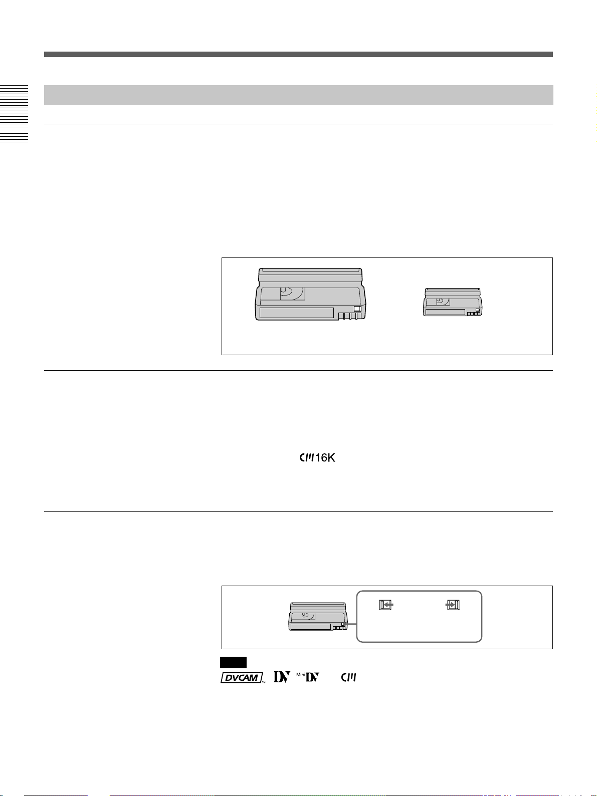
Use Standard-DVCAM cassettes or Mini-DVCAM cassettes with this
VCR. PDV-184ME can record programs for 184 minutes and PDVM40ME can record for 40 minutes.
You can get the highest quality pictures with this digital videocassette
recorder using DVCAM cassettes. You may not be able to get as good
quality with other cassettes. We recommend using DVCAM cassettes so
that you can record your one-time events in highest quality.
Cassette memory
To save a recording
DVCAM cassette Mini DVCAM
cassette
Cassette memory is an optional feature that is mounted on some Standard
DVCAM cassettes and Mini DVCAM cassettes. When you record a
program, the recording date and time, and the programs’ position on the
tape are stored in the cassette memory so that you can quickly locate the
program later on.
indicates that you can use the cassettes 16 Kbits
of data can be stored on. On this VCR, you can use the cassettes up to
16 Kbits of data can be mounted on.
To prevent accidental erasure of a recording, slide in the safety switch on
the cassette so that the red portion becomes visible. To record on a tape,
slide out the switch so that the red portion is hidden.
Write protected
Write enabled
GB
8
Chapter 1 Overview
Note
, , and are trademarks.
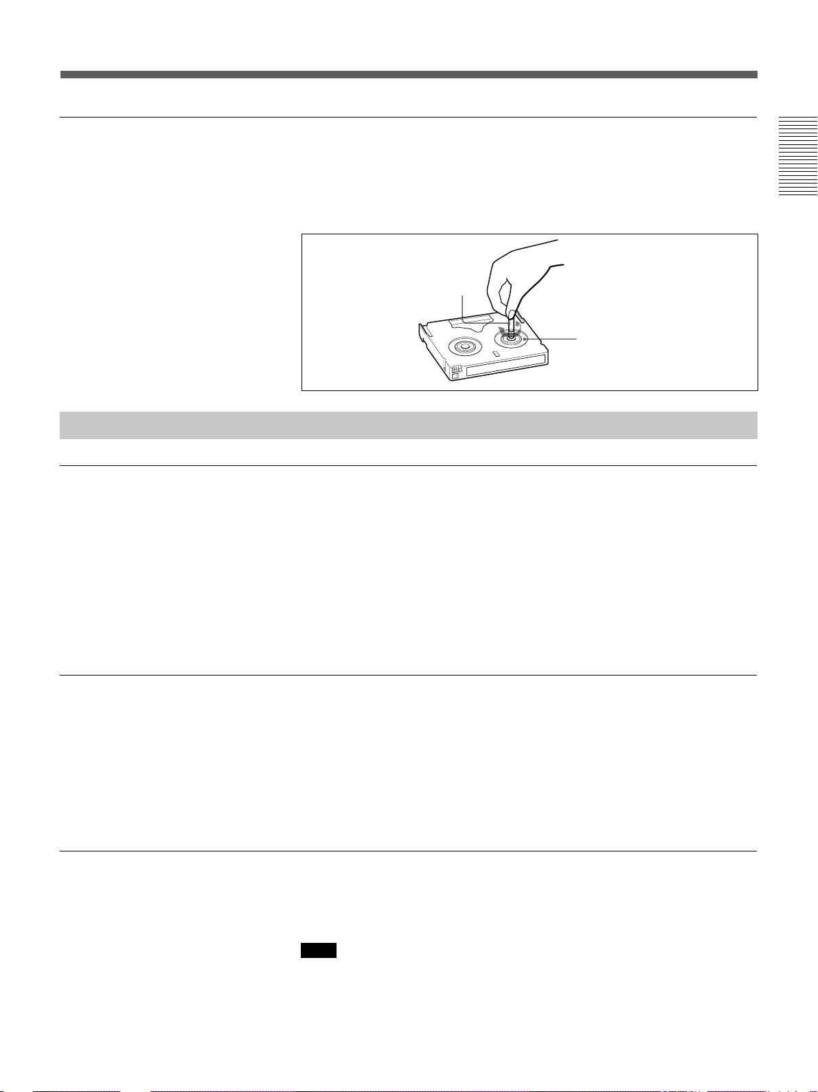
Checking the tape for slack
Notes on Recording / Playing
Copyright precautions
Using a paper clip or a similar object, turn the reel gently in the direction
shown by the arrow. If the reel does not move, there is no slack. Insert the
cassette into the cassette compartment, and after about 10 seconds take it
out.
Paper clip, etc.
Reel
On recording
You cannot record any software having copyright protection signals on this
VCR. If you start recording protected video and audio signals, a warning
message appears on the monitor screen and the VCR stops recording.
Chapter 1 Overview
On playback
When you play back software having copyright protection signals on this
VCR, you may not be able to copy it onto other equipment.
Limitations caused by the difference in format
This VCR can record, play back and edit the tapes recorded in DVCAM
format. It can also play back the tapes recorded in DV format (SP mode).
However, due to the difference in format, you may not be able to record or
edit some tapes affected by recording conditions of the tape (e.g., A tape
originally recorded in DV format is dubbed in DVCAM format). For
details, refer to “Compatibility of DVCAM and DV format” on page 62.
No compensation for contents of the recording
Contents of the recording cannot be compensated for if recording or
playback is not made due to a malfunction of the VCR, video tape, etc.
Note
You cannot play back a DVCAM tape recorded in other color systems on
this VCR.
Chapter 1 Overview 9
GB
Location and Function of Parts
Location and Function of Parts
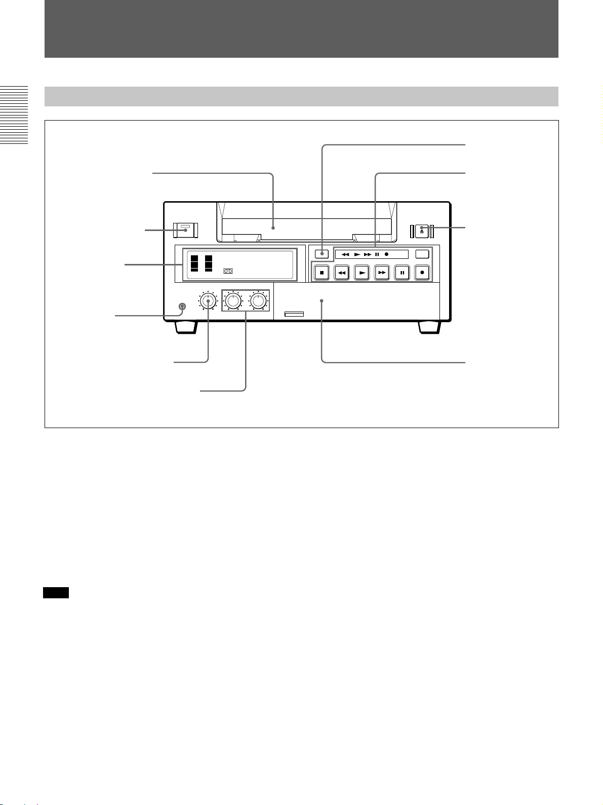
Front Panel
Chapter 1 Overview
1 Cassette compartment
2 ON/STANDBY switch
and ON/STANDBY lamp
1 Display section
(see page 11)
3 PHONES jack
4 PHONE LEVEL control knob
5 AUDIO INPUT LEVEL control knobs
INPUT
SELECT
COUNTER
TAPE
REMAIN
COUNTER
SELECT
TC
MONITOR
CH-1/2
MIX
CH-3/4
AUDIO
REPEAT
6 COUNTER RESET
button
2 Tape transport
control section
(see page 12)
7 EJECT button
DUP
TIMER
REMOTE
OFF
REC
LOCAL
MENU
SET
3 Inside of the door
(see page 13)
1 Cassette compartment
Accepts standard-size or mini-size DVCAM digital
videocassettes. When using a mini-size cassette, insert
it into the center of the compartment.
For details of usable cassettes, see page 8.
2 ON/STANDBY switch and ON/STANDBY lamp
Press this switch to turn on the power, and the ON/
STANDBY lamp lights in green. Press it again to turn
to standby mode, and the lamp lights in red.
Note
When the REMOTE/LOCAL switch is set to
REMOTE, you cannot turn the unit to standby mode.
3 PHONES jack (stereo minijack)
Connect stereo headphones for headphone monitoring
during recording or playback.
The audio signal you want to monitor can be selected
with the AUDIO MONITOR selector inside of the
door (3).
4 PHONE LEVEL control knob
Controls the volume of the headphones connected to
the PHONES jack.
5 AUDIO INPUT LEVEL control knobs
When recording, you can use these knobs to set audio
input levels for CH-1 (channel 1) and CH-2 (channel
2), respectively.
6 COUNTER RESET button
Press this button to reset the tape counter in the display
window to “0:00:00 (0
H00M00S)”. This button does not
work when displaying the time code or the remaining
time.
7 EJECT button
Press this button to eject a cassette.
10
GB
Chapter 1 Overview
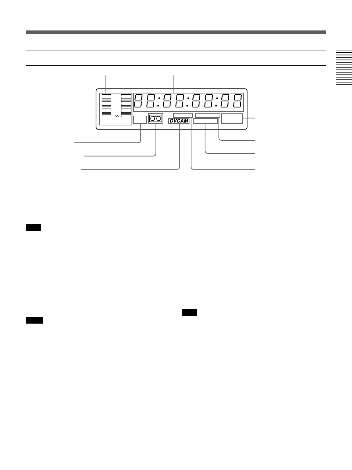
1 Display section
1 Audio level meter
0
6
9 Mini indicator
8 Cassette indicator
7 DVCAM indicator
12
24
–
CH 1/3 CH 2/4
HOURS MINUTES SECONDS FRAMES
Mini
1 Audio level meter
Indicates the recording level during recording or EE
mode, and the playback level during playback. When
the audio level exceeds 0 dB, the red indicator lights.
Note
If you play back the tape whose audio was only
recorded on channel 2, the audio level meter for CH2/4
may not function.
2 Time counter display
Indicates the following:
•Time data: count value of the time counter, time code
and remaining time.
•Alarm messages (see page 55).
•Messages for self-diagnosis function (see page 59).
Notes
•For DSR-40P: Time code is set to the non drop frame
mode only.
•Time code is indicated as follows:
Drop frame: “00:00.00:00” (DSR-40 only)
Non drop frame: “00:00:00:00”
3 Video input signals indicators
Indicates the currently selected video input signals.
INPUT VIDEO, INPUT S VIDEO, or INPUT DV
lights.
4 NS (Non Standard) AUDIO indicator
Lights when the VCR plays back a tape whose audio
recording was made in the unlock mode, or when unlock
mode signals are input through the DV jack.
For details of unlock mode, see page 62.
2 Time counter display
TIMER INPUT DV
NS AUDIO
Fs32k Fs48k
S VIDEO
3 Video input signals
indicators
4 NS AUDIO indicator
5 Audio mode indicators
6 TIMER indicator
5 Audio mode indicators
Indicates the audio mode during playback or recording
or while in EE mode.
•During playback it indicates the audio mode in which
the tape was recorded.
•During recording or while in EE mode, it indicates
the currently selected audio recording mode. You can
select audio recording mode by setting “AUDIO
MODE” menu (see page 53).
Fs32k: Lights when playing the tapes recorded in
4-channel mode, or recording a tape in 4-channel
mode.
Fs48k: Lights when playing the tapes recorded in
2-channel mode, or recording a tape in 2-channel
mode.
Note
When recording in 4-channel mode on this VCR, audio
signals are recorded only in channels 1/2.
6 TIMER indicator
Lights when setting the TIMER switch to REPEAT.
7 DVCAM indicator
Lights except playing back the DV-formatted tapes.
8 Cassette indicator
Lights when inserting a digital video cassette available
for this VCR. It flashes when ejecting a cassette.
9 Mini indicator
Lights when inserting mini-size digital video cassette.
Chapter 1 Overview
Chapter 1 Overview 11
GB
Location and Function of Parts
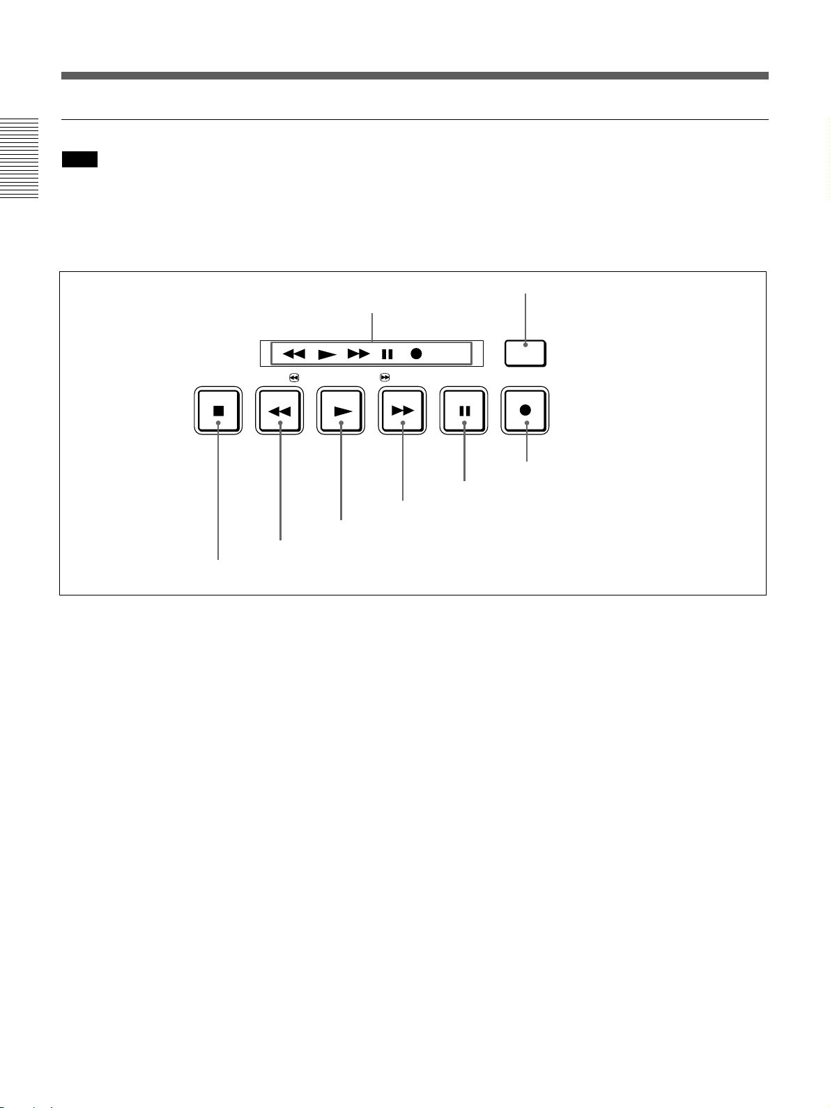
2 Tape transport control section
Note
When the tape reaches to its beginning or its end by
rewinding or fast-forwarding, the unit turns to
Chapter 1 Overview
playback pause mode. Then, the playback pause mode
is released after the time which is set at “STILL
TIMER” menu (See page 52).
2 DUP button
1 Tape Transport indicators
STOP REW PLAY F FWD PAUSE REC
6 PLAY button
7 REW button
8 STOP button
1 Tape Transport indicators
2 DUP (duplicate) button
Use this button to make a work tape having the same
time codes as the source tape.
For details on duplication, see page 28.
3 REC (record) button
When you press the PLAY button while holding down
this button, the indicator lights and recording begins.
To set the VCR to recording pause mode, press the
PAUSE button while holding down this button.
4 PAUSE button
When you press this button, the indicator lights, and
the VCR is set to pause mode.
5 F FWD (fast forward) button
When you press this button, the indicator lights and the
tape is fast forwarded. During fast forward, the picture
does not appear on the monitor (you can see the
picture of the EE mode during fast forward).
To search forward, hold this button down during fast
forward.
DUP
4 PAUSE button
5 F FWD button
DUP
3 REC button
6 PLAY button
When you press this button, the indicator lights and
playback begins.
If you press this button while holding down the REW
button during stop, the tape is rewound to its beginning
and starts playing automatically (during rewind, the
REW indicator lights and the PLAY indicator flashes).
7 REW (rewind) button
When you press this button, the indicator lights and the
tape starts rewinding. During rewind, the picture does
not appear on the monitor (you can see the picture of
the EE mode during rewind).
To search backward, hold this button down during
rewind.
If you press the PLAY button while holding down this
button during stop, the tape is rewound to its beginning
and starts playing automatically (during rewind, the
REW indicator lights and the PLAY indicator flashes).
8 STOP button
Press this button to stop the current tape transport
operation.
12
GB
Chapter 1 Overview
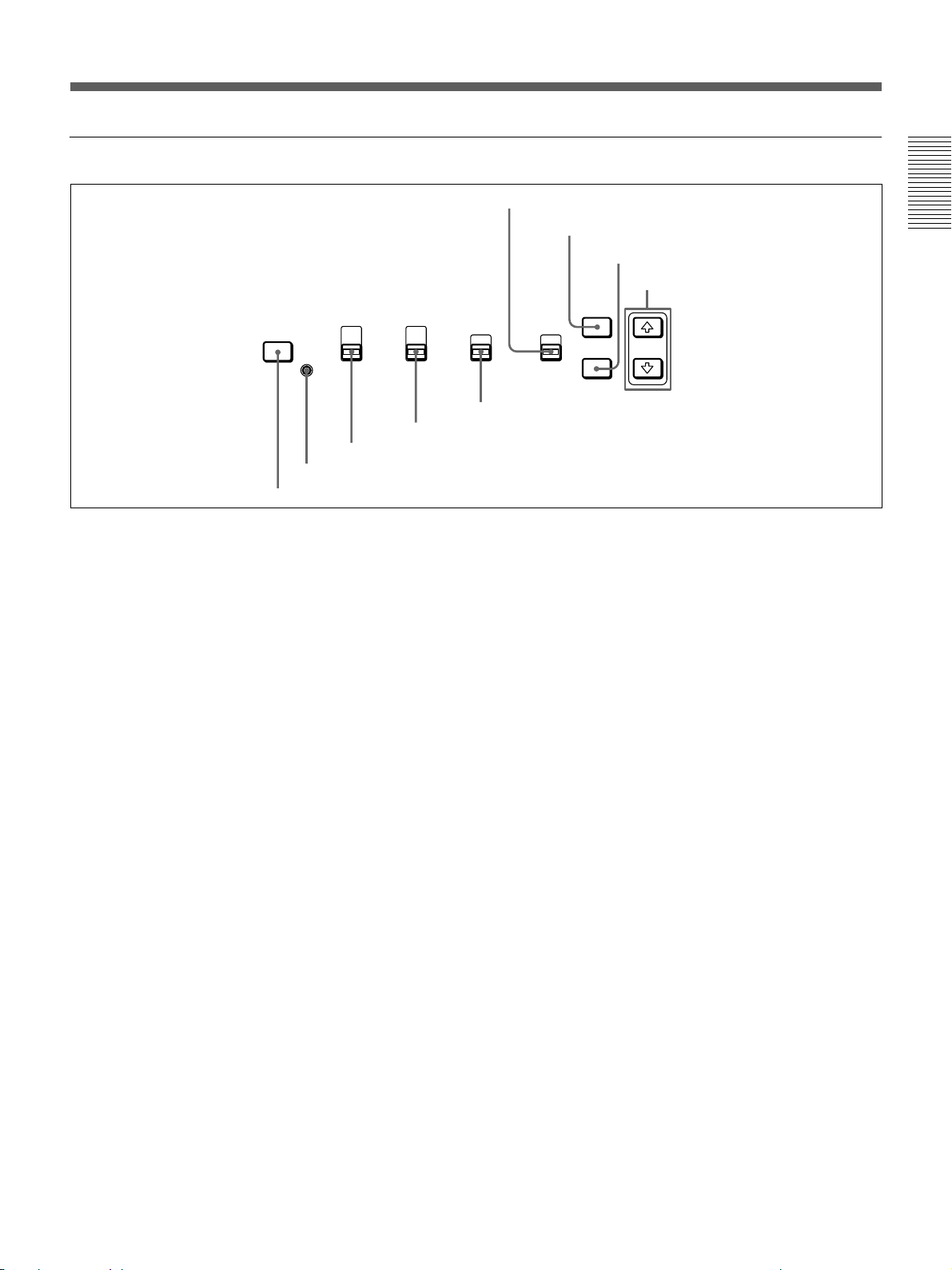
3 Inside of the door
6 REMOTE/LOCAL switch
COUNTER
INPUT
SELECT
1 INPUT SELECT button
SELECT
TC
COUNTER
TAPE
REMAIN
CL
2 CL button
3 COUNTER SELECT selector
AUDIO
MONITOR
CH-1/2
MIX
CH-3/4
REPEAT
4 AUDIO MONITOR selector
1 INPUT SELECT button
Selects input signals. Each press of this button cycles
through three video signal selection options: video, Svideo, and DV input. When you select one of these
options, the corresponding indicator in the display
lights up.
2 CL (Clear) button
Press this button to make the unit to the state of
reconnecting the AC power cord. When you press this
button, the setting in the menu is not initialized.
3 COUNTER SELECT selector
Select the type of time data in the time counter display.
TC: Time code
COUNTER: Count value of the time counter
TAPE REMAIN: Remaining time
4 AUDIO MONITOR selector
Use to select the audio track you want to hear when
playing back a tape recorded in 4-channel mode
(Fs32k).
CH-1/2: Channels 1/2 only
MIX: Channels 1/2 and channels 3/4 (mix)
CH-3/4: Channels 3/4 only
7 MENU button
8 SET button
9 Arrow (˘ ≥) buttons
TIMER
OFF
REMOTE
MENU
LOCAL
SET
5 TIMER switch
5 TIMER switch
Use to select Auto Repeat using an external AC timer
(not supplied).
REPEAT: When the power is supplied to this VCR,
a tape rewinds to its beginning automatically and
playback starts. The VCR repeats the playback
from the beginning to the first index (if there is no
index on the tape, to the unrecorded portion; if no
unrecorded portion, to the tape end). Auto repeat
also functions if you set this switch to REPEAT
during playback.
OFF: Auto Repeat is released.
6 REMOTE/LOCAL switch
Selects whether the unit is operated from its front
panel or from external (remote) equipment.
REMOTE : The unit is operated from an editing
controller connected to the REMOTE connector.
Available tape transport buttons (on the front
panel or optional remote control unit) are set in
the menu.
LOCAL : The unit is operated from its front panel,
or from a SIRCS-system remote control unit
connected to the CONTROL S jack.
Chapter 1 Overview
Chapter 1 Overview 13
GB
Location and Function of Parts
7 MENU button
Press this button to display the menu on the monitor
screen. Press it again to return from the menu display
to the usual display.
Chapter 1 Overview
Note
If you set the REMOTE/LOCAL switch to REMOTE
while the menu display is on the monitor, it returns to
the usual display.
On how to use the menu, see Chapter 5 “Menu Settings”.
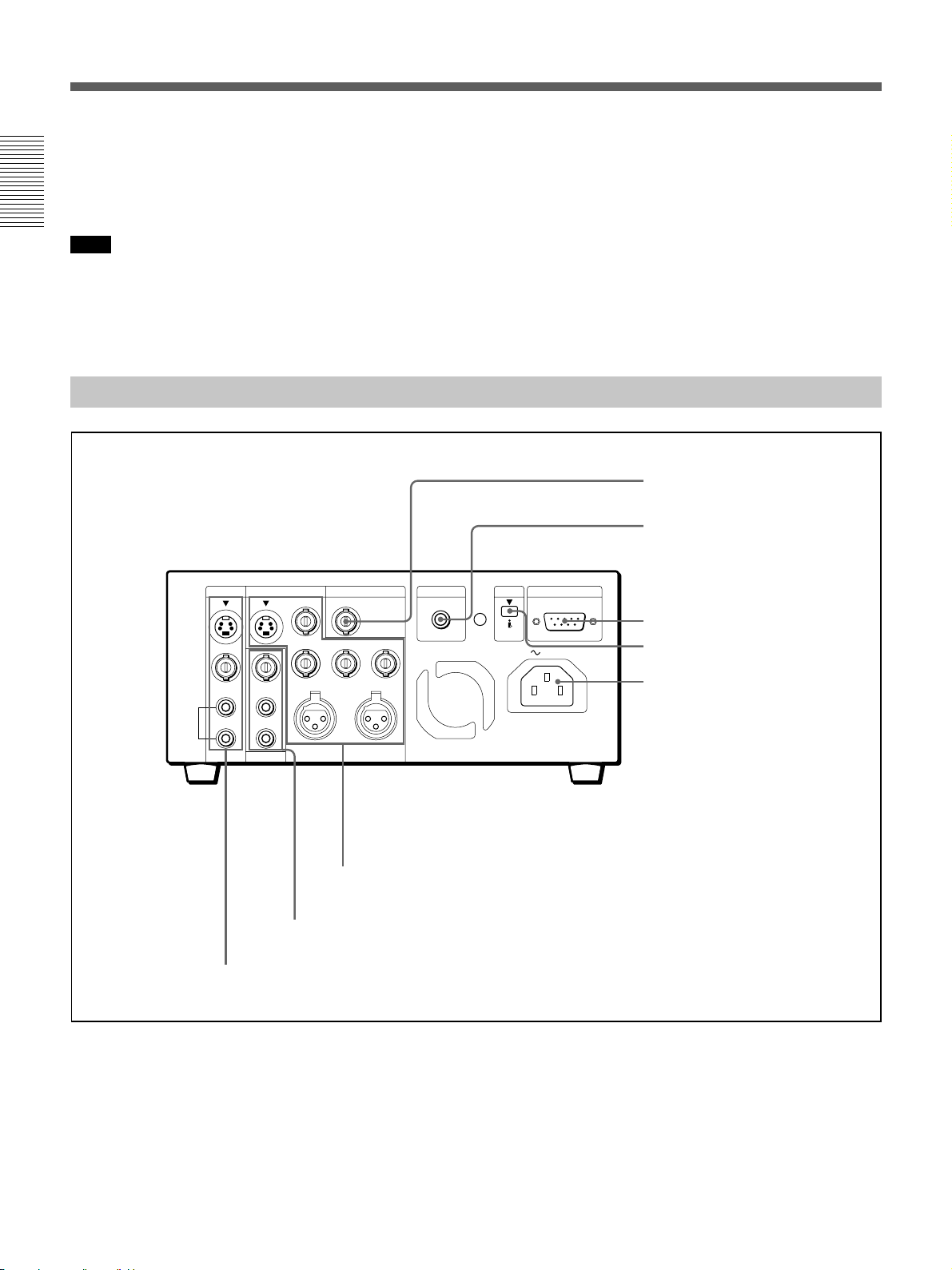
Rear Panel
S VIDEO
VIDEO
AUDIO
INPUT OUTPUT
CH-1
CH-1/3
CH-2
CH-2/4
REF.VIDEO INPUT
VIDEO
Y
R-Y B-Y
AUDIO CH-1/3 AUDIO CH-2/4
CONTROL S
8 SET button
Press this button to save selected menu items to the
unit’s memory.
9 Arrow (J j) buttons
Use these buttons to move around the menu items.
4 REF. VIDEO INPUT connector
5 CONTROL S jack
DV
REMOTE
RS-422A
IN/OUT
AC IN
6 REMOTE connector
7 DV jack
8 AC IN connector
MONITOR
3 OUTPUT connectors
2 MONITOR connectors
1 INPUT connectors
1 INPUT connectors
Input video and audio signals. To connect a VCR
equipped with the S-video output jack, use the
S VIDEO jack on this VCR.
2 MONITOR connectors
Output video and audio signals for monitoring.
3 OUTPUT connectors
Output video and audio signals. To connect a VCR
equipped with the S-video input jack, use the S
VIDEO jack on this VCR. To connect a VCR
equipped with the component input connectors, use the
Y, R–Y, B–Y connectors on this VCR.
14
GB
Chapter 1 Overview

Note on EE mode
When the S-video, video, or DV signal is input, this
VCR cannot output component signals. You can only
output the component signal during normal playback.
4 REF. VIDEO INPUT connector (BNC-type)
Input a reference video (black burst) signal.
5 CONTROL S jack
When controlling this VCR from an optional remote
control unit such as the DSRM-10/20 (not supplied),
connect the unit to this jack.
Note
SIRCS-system has the same function as
CONTROL S-system.
6 REMOTE connector (D-sub 9-pin)
Connect an editing controller with the RS-422A
interface for remote-control of this VCR.
7 DV jack
The DV jack is i.LINK compatible. Use when the
equipment connected to the VCR has a DV jack.
If you connect the VCR and the other equipment using
DV jacks, you can minimize deterioration of picture
quality during dubbing, or capturing still pictures by
digital processing. For details, refer to the instruction
manual of the equipment you use.
Chapter 1 Overview
Note
is a trademark of Sony Corporation and indicates
that this product is in agreement with IEEE1394-1995
specifications and their revisions.
8 AC IN connector
Connect to an AC power outlet using the supplied
power cord.
Chapter 1 Overview 15
GB
Playback
Playback
This section describes the necessary connections, settings and operations
to perform playback on this unit. The same settings and operations apply
whether you are using the unit as part of an editing system, for dubbing, or
as a stand-alone videocassette player.
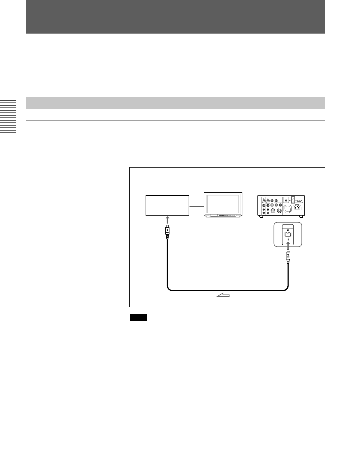
Connections for Playback
To digital video equipment with the DV jack
Chapter 2 Playback and Recording
The video and audio signals are sent with hardly any degradation, enabling
high-quality recording. The signal flow is automatically detected so you
need not make separate connections for input and output.
Recorder
to the DV
jack
Monitor
i.LINK cable (DV connecting cable)
(not supplied)
This VCR (Player)
DV
IN/OUT
L: Signal flow
16
GB
Chapter 2 Playback and Recording
Notes
•The external lock function of this unit only supports the standard sync
signals. With the DV connection, select the DV input with the INPUT
SELECT button on this VCR to prevent malfunction resulting from
noise, etc.
•Set DV EE OUT in the menu to OFF (see page 52).
•With the DV connection, the sound is recorded in the same audio
recording mode as that of the source tape.
•With the DV connection, tape information (recording date, camcorder
data, etc.) recorded on the source tape is transmitted from this VCR
(player).
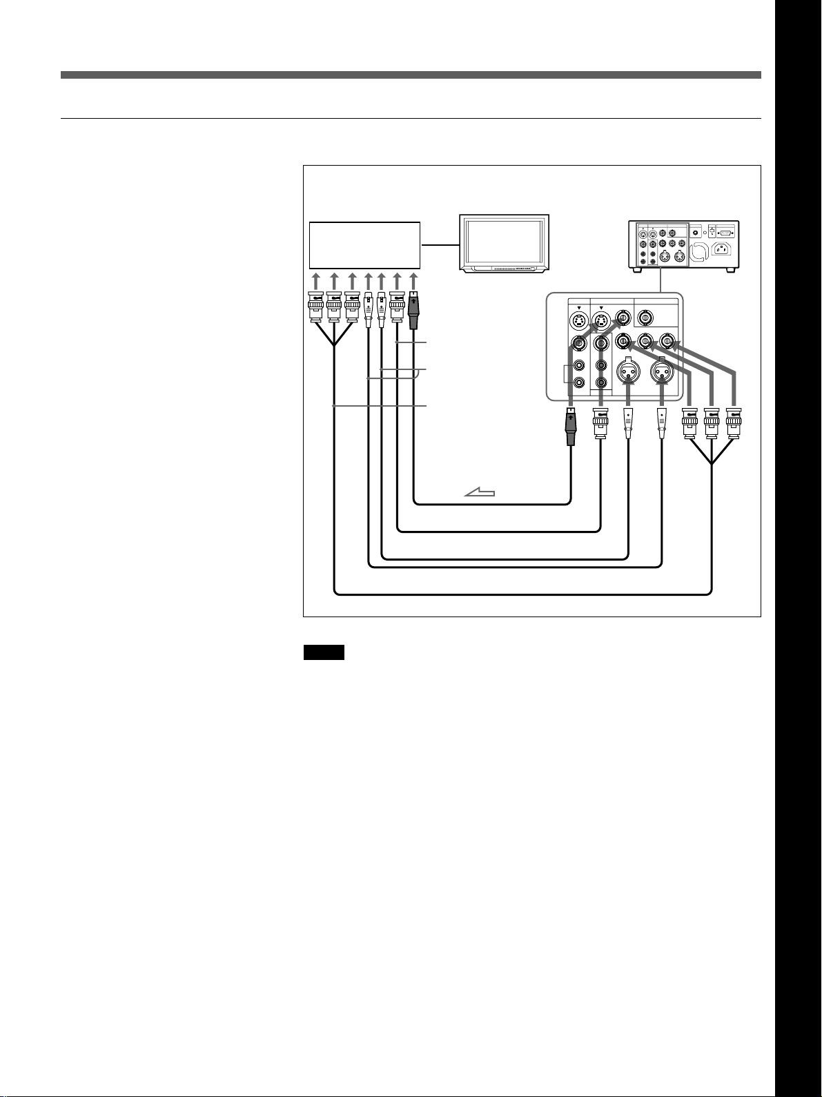
To video equipment without the DV jack
Chapter 2 Playback and Recording
Recorder
Monitor
INPUT OUTPUT
S VIDEO
S VIDEO
VIDEO
VIDEO
AUDIO
AUDIO
INPUT OUTPUT
CH-1
CH-1/3
CH-1
CH-1/3
CH-2
CH-2/4
CH-2
CH-2/4
MONITOR
MONITOR
to the S-video
input jack
to the video
input jack
to the audio
input jacks
to the video
input jacks
S-video cable (not supplied)
75 Ω coaxial cable (not supplied)
XLR cable (not supplied)
Video cable (3BNCy3BNC) (not supplied)
This VCR (Player)
REF.VIDEO INPUT
REF.VIDEO INPUT
VIDEO
VIDEO
Y
R-Y B-Y
Y
R-Y B-Y
AUDIO CH-1/3 AUDIO CH-2/4
AUDIO CH-1/3 AUDIO CH-2/4
L: Signal flow
Chapter 2 Playback and Recording
Notes
•When you connect output jacks of the recorder to input jacks of this
VCR, select the input correctly to prevent a humming noise.
•Distorted signals (e.g., when played back at a speed other than normal)
will not be recorded properly.
•The indications (Time code, alarm messages, and menu, etc.) displayed
on the monitor screen are output only via the MONITOR connector.
•If the DV input is selected, you cannot perform the playback
synchronized with the video reference (black burst) signal.
Chapter 2 Playback and Recording 17
GB

Playback
Settings for Playback
Preparation on the player (this VCR)
Chapter 2 Playback and Recording
1 Power on the video monitor, then set the monitor’s input according to
the input signals from the recorder.
2 Set up the recorder.
For details, see “Preparation on the recorder” below.
3 Power on this unit by pressing the ON/STANDBY switch.
The ON/STANDBY lamp lights in green.
4 When you play back a tape recorded in 4-channel mode (Fs 32k), set
the AUDIO MONITOR selector to MIX (see page 13). Then select the
precise balance between the tracks with the AUDIO MIX BALANCE
in the menu (see page 53).
Preparation on the recorder
Notes
•With the DV connection, the playback VCR’s AUDIO MONITOR
(sound selection) and AUDIO MIX BALANCE (audio balance
adjustment) do not function on the source audio output through the DV
jack.
•You cannot change the input signal selection during playback or playback
pause mode.
•Insert a tape for recording.
•Select the video and audio input signals to be recorded.
Note
Editing is not possible with a tape that is copyright protected.
18
GB
Chapter 2 Playback and Recording
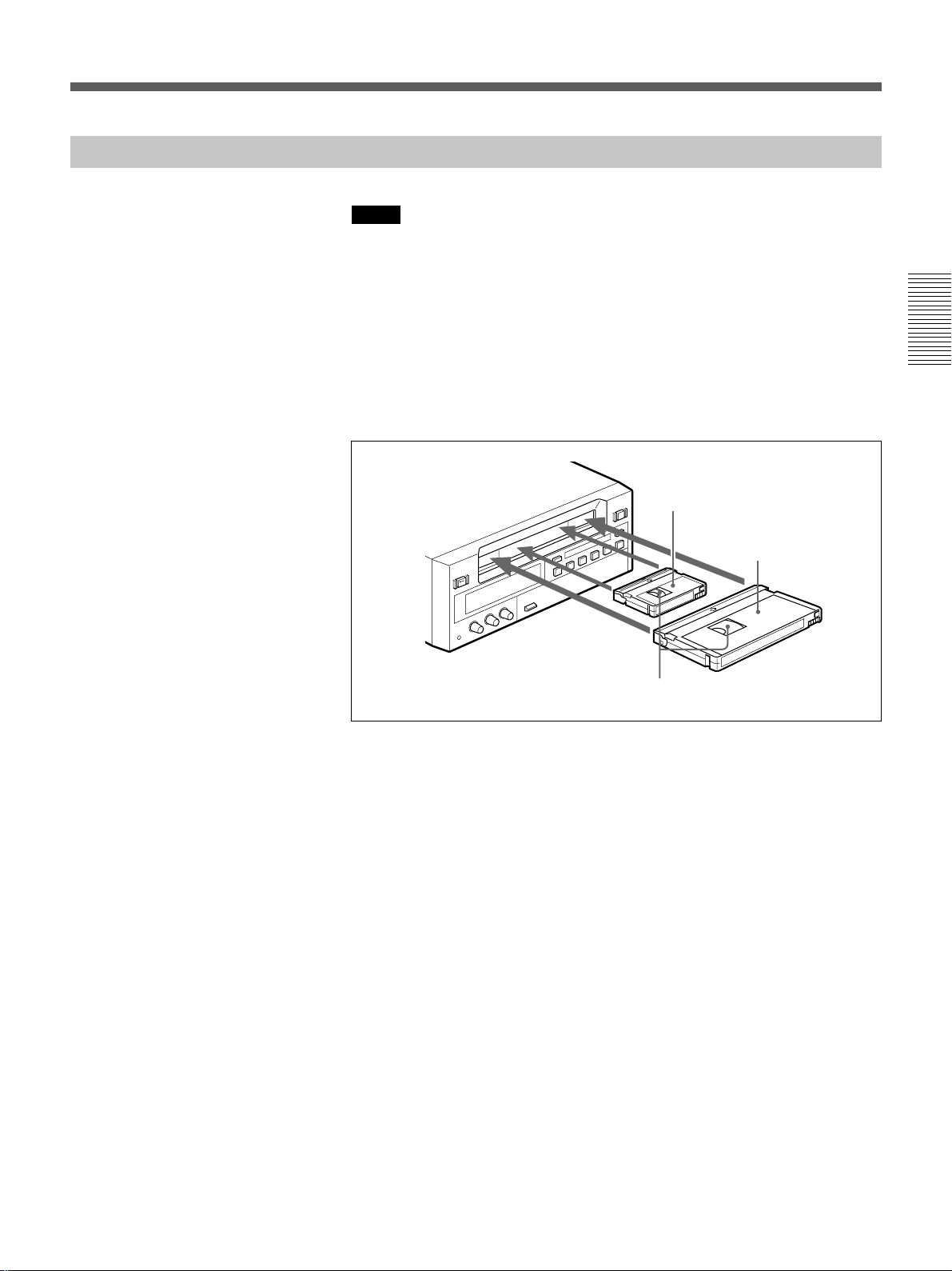
Playback Procedure
Notes
•When controlling this unit from an editing controller connected to the
REMOTE connector, set the REMOTE/LOCAL switch to REMOTE.
When not, set it to LOCAL.
•Do not insert the cassette forcibly. The VCR may be damaged.
1 After checking the tape for slack, hold the cassette so that the tape
window is facing upward, then insert it into this unit as illustrated
below.
For details on checking the tape for slack, see page 9.
Mini size
Insert the mini-size cassette into
the center of the cassette
compartment.
Standard size
Chapter 2 Playback and Recording
Tape window facing upward
The cassette is automatically drawn into the unit.
2 Press PLAY.
This starts the playback operation.
Chapter 2 Playback and Recording 19
GB

Playback
Playback Functions
You can enjoy various playback functions using the optional remote
control unit.
For details, refer to the operating instructions supplied with the remote control
unit.
Playing at various speeds (JOG)
You can play at various speeds, or frame by frame.
Chapter 2 Playback and Recording
Searching (SHUTTLE)
You can easily locate the desired scene, and you can quickly and
accurately determine edit points.
Searching using the index function (DSRM-20 only)
Three kinds of search are available on this VCR:
– Searching for the beginnings of recordings: Index search
– Searching for a point on the tape where the recorded date changes:
Date search
– Searching for scenes recorded in the photo mode with a digital
camcorder: Photo search
Note
When S-video or video input is selected and no signal is input in search
mode, the search screen becomes noisy. In such cases, input the signal or
select DV input.
For a description of search operations via external equipment, see the
equipment’s operating instructions.
Displaying tape information (DSRM-20 only)
If you record on a tape using a Sony digital camcorder DSR-200/200P/
200A/200AP/PD100/PD100P, camcorder data (the shutter speed, program
AE mode, white balance, iris and gain) can be recorded on the tape. You
can check these data during playback on this VCR.
20
GB
Chapter 2 Playback and Recording
Auto Repeat
This VCR can repeat the playback of all, or a part of the tape.
1 Set the TIMER switch on the front panel to REPEAT.
The TIMER indicator on the front panel lights.
2 Press REW to rewind the tape to its beginning.
3 Press PLAY.
Playback starts. The VCR repeats the playback from the beginning to
the first index (if there is no index on the tape, to the unrecorded
portion; if no unrecorded portion, to the tape end).
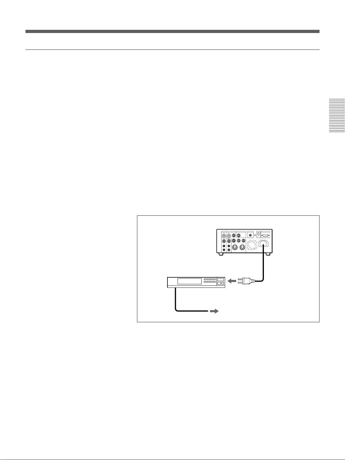
Auto Repeat using an external AC timer
If you connect an external AC timer (not supplied) to this VCR, you can
repeat playback automatically at the preset time.
1 Connect an external AC timer (not supplied) to this VCR.
This VCR
AC timer
Chapter 2 Playback and Recording
to a wall outlet
2 Set the TIMER switch on the front panel to REPEAT.
The TIMER indicator in the display window lights.
3 Set the start time using the external AC timer.
At the preset time, the power turns on, and Auto Repeat playback starts
automatically within one minute. The VCR repeats the playback from
the beginning to the first index (if there is no index on the tape, to the
unrecorded portion; if no unrecorded portion, to the tape end).
Chapter 2 Playback and Recording 21
GB

Playback
Chapter 2 Playback and Recording
Notes
•The VCR cannot search for an index or unrecorded portion within 20
seconds from the beginning of the tape.
•While a tape is running, do not turn off the power using an AC timer. The
VCR and a tape may be damaged. When turning off the power of the
VCR, make sure to press the STOP button on this VCR first to stop the
tape transport, then turn off the power.
To stop Auto Repeat
Press the STOP button.
To release Auto Repeat mode
Set the TIMER switch to OFF.
22
GB
Chapter 2 Playback and Recording

Recording
This section describes the necessary connections, settings and operations
to perform recording on this unit. The same settings and operations apply
whether you are using the unit as part of an editing system, for dubbing, or
as a stand-alone recorder.
Connections for Recording
To digital video equipment with the DV jack
The video and audio signals are sent with hardly any degradation, enabling
high-quality recording. The signal flow is automatically detected so you
need not make separate connections for input and output.
Player
to the DV
jack
Monitor
i.LINK cable (DV connecting cable)
(not supplied)
This VCR (Recorder)
DV
IN/OUT
l: Signal flow
Chapter 2 Playback and Recording
Notes
•With the DV connection, the sound is recorded in the same audio
recording mode as that of the source tape. To record in a different audio
recording mode from the source tape, use the INPUT connectors instead.
•With the DV connection, tape information (recording date, camcorder
data, etc.) recorded on the source tape is transmitted from the other VCR
(player). As a result, when you play back a recorded tape and press the
DATA CODE button on the optional DSRM-20 remote control unit, the
same tape information recorded on the source tape is displayed on the
monitor screen. However, contents of the cassette memory are not
transmitted. In addition, the time code is newly recorded on the tape on
this VCR, except when copying a tape in Duplication mode.
Chapter 2 Recording and Playback 23
GB
Recording
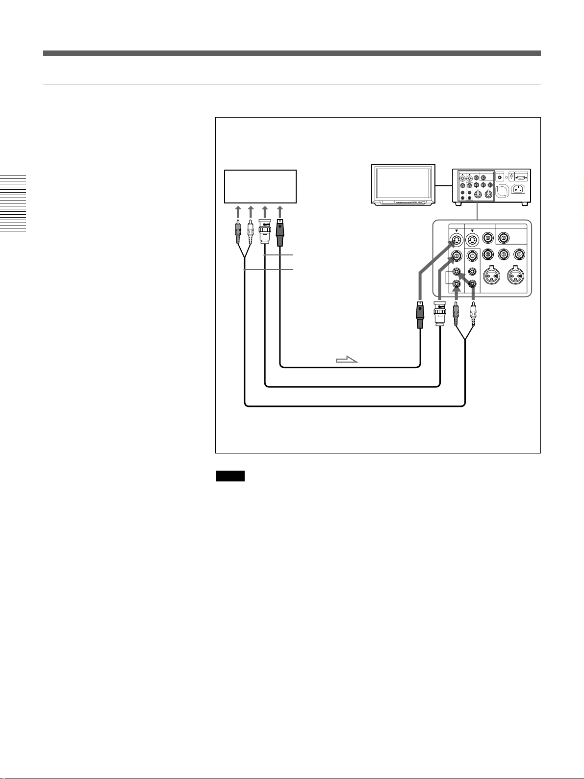
To video equipment without the DV jack
Chapter 2 Playback and Recording
Monitor
to the S-video output
jack
to the video output jack
to the audio
output jacks
S-video cable (not supplied)
75 Ω coaxial cable (not supplied)
Audio cable (not supplied)
S VIDEO
S VIDEO
VIDEO
VIDEO
AUDIO
AUDIO
This VCR (Recorder)Player
INPUT OUTPUT
INPUT OUTPUT
CH-1
CH-1
CH-2
CH-2
VIDEO
VIDEO
Y
Y
AUDIO CH-1/3 AUDIO CH-2/4
AUDIO CH-1/3 AUDIO CH-2/4
CH-1/3
CH-1/3
CH-2/4
CH-2/4
MONITOR
MONITOR
l: Signal flow
REF.VIDEO INPUT
REF.VIDEO INPUT
R-Y B-Y
R-Y B-Y
24
GB
Chapter 2 Recording and Playback
Notes
•When recording the analog input signals, this VCR can digitally output
the signals from the DV jack for backup. Set DV EE OUT in the menu to
ON (see page 52).
•When you connect output jacks of this VCR to input jacks of the player,
select the input correctly to prevent a humming noise.
•Distorted signals (e.g., when played back at a speed other than normal)
will not be recorded properly.
•The indications (Time code, alarm messages, and menu, etc.) displayed
on the monitor screen are output only via the MONITOR connector.
Settings for Recording
Preparation on the recorder (this VCR)
Notes
•Before recording, set the clock on the VCR so that the recording time can
be written into the index signal. You can set the clock by setting the
CLOCK SET menu (see page 53).
•When controlling this unit from an editing controller connected to the
REMOTE connector, set the REMOTE/LOCAL switch to REMOTE.
When not, set it to LOCAL.
•Editing is not possible with a tape that is copyright protected.
1 Power on the video monitor, then set the monitor’s input according to
the input signals from this unit.
2 Set up the player to play back a tape.
For details, see “Preparation on the player” on the next page.
3 Power on this unit by pressing ON/STANDBY switch.
Chapter 2 Playback and Recording
The ON/STANDBY lamp lights in green.
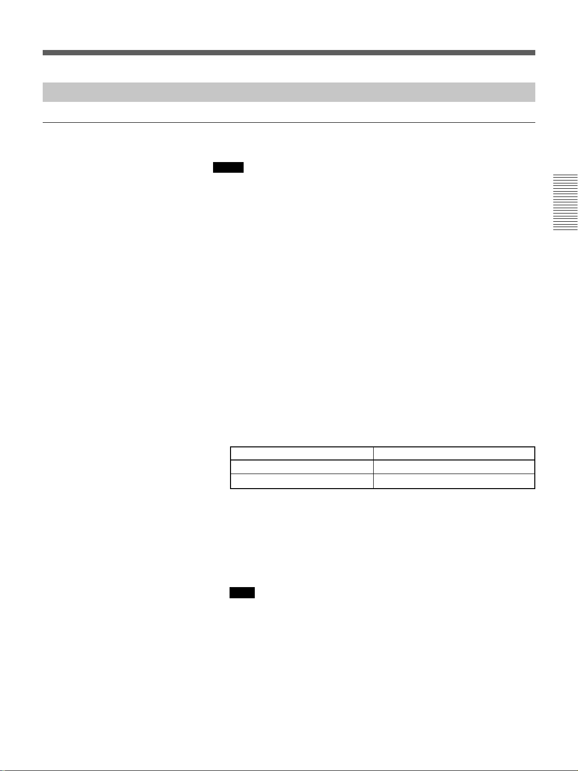
4 Use the COUNTER SELECT selector to select the type of time data to
be used.
Type of time data
Time code
Count value of the time counter
Set the selector to
TC
COUNTER
5 Select the video and audio input signals to be recorded.
Press INPUT SELECT to select the desired signal. Each press of this
button cycles through three signal selection options: video, S-video,
and DV input. Each selection is shown by a lit indicator in the display
window.
Note
Once you have started recording, you cannot change the input signal
selection (except during recording pause mode).
Chapter 2 Recording and Playback 25
GB
Recording
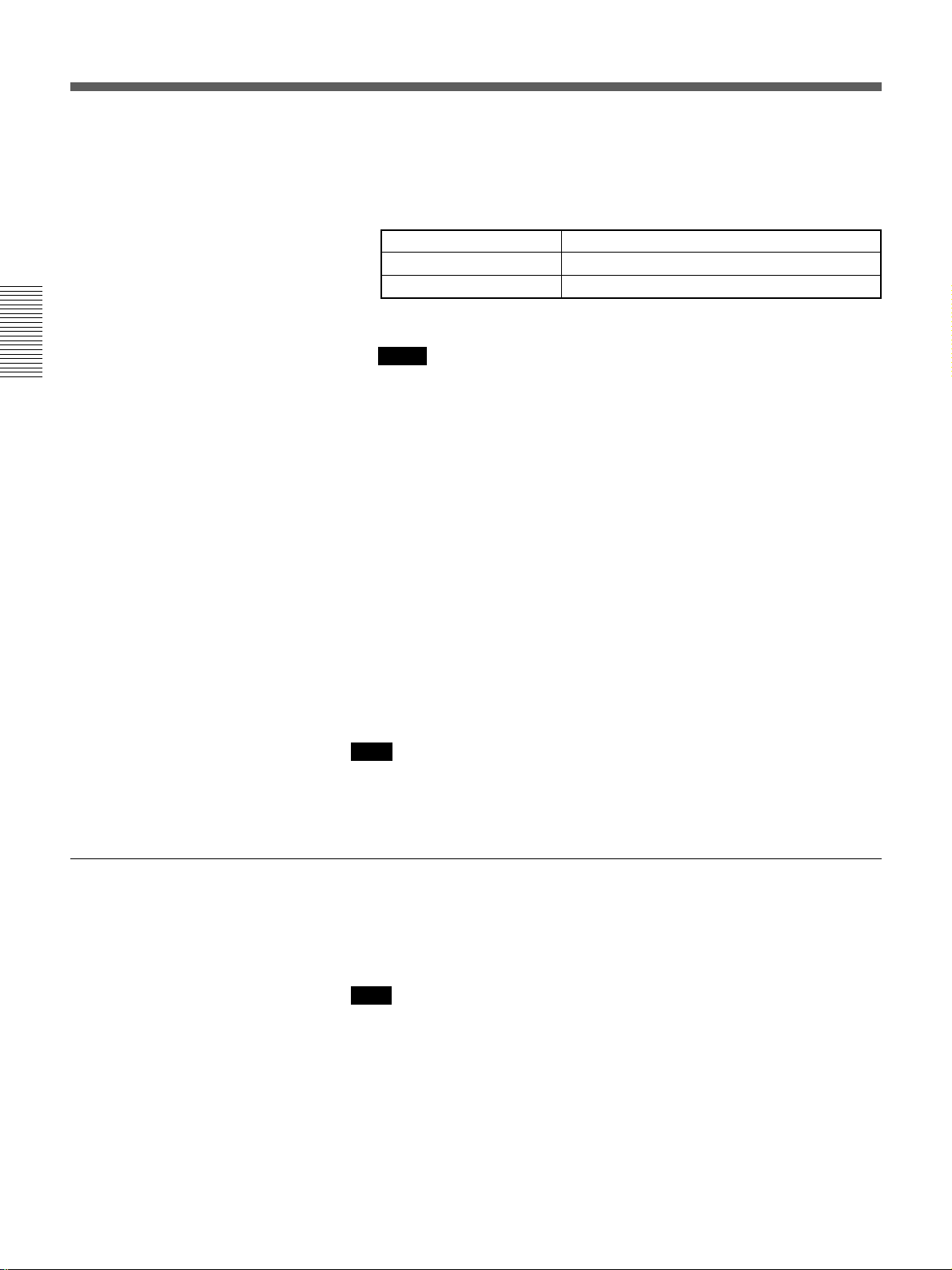
6 When using the line connections (INPUT connectors), select the audio
mode.
Select the desired mode by setting the AUDIO MODE menu.
Chapter 2 Playback and Recording
Audio mode
2-channel mode
4-channel mode
On how to use the menu, see Chapter 5 “Menu Settings”.
Notes
Set the menu to
Fs48k
Fs32k
•In the DVCAM format, there are two audio recording modes, with
either two channels at 48 kHz or four channels at 32 kHz. It is not
possible to select other modes (for example with four channels at
48 kHz).
•When recording in 4-channel mode on this VCR, audio signals are
recorded only in channels 1/2.
•Once you have started recording, you cannot change the audio mode
selection.
7 Use the AUDIO INPUT LEVEL control knobs to adjust audio input
levels.
Watching the audio level meter (see page 11), adjust the level so that
the meter does not indicate higher values than 0 dB when the audio
signal is at its maximum.
When the level exceeds 0 dB, sound distortion occurs.
Preparation on the player
Note
With the DV connection, the recorder VCR’s AUDIO MODE (sound
selection) and AUDIO INPUT LEVEL (audio balance adjustment) do not
function.
•Insert a source tape.
•If the player VCR has an EDIT switch, set it to ON.
•Turn off the on-screen display.
Note
With the DV connection, the playback VCR’s AUDIO MONITOR (sound
selection) and AUDIO MIX BALANCE (audio balance adjustment) do not
function on the source audio output through the DV jack.
26
GB
Chapter 2 Recording and Playback

Recording Procedure
1 After checking that the cassette’s safety switch is set to write enabled
position and the tape for slack, hold the cassette so that the tape
window is facing upward, then insert it into this unit.
For details of the cassette’s safety switch, see page 8. For details of checking
the tape for slack, see page 9.
The cassette is automatically drawn into the unit and the tape is wound
round the head drum. The tape is stationary while the head drum
rotates.
2 Press the playback button on the player.
This starts the player’s playback operation.
3 Press and hold REC on this VCR, and press PLAY.
This starts the recorder’s recording operation.
To stop recording
Press the STOP button.
Chapter 2 Playback and Recording
Chapter 2 Recording and Playback 27
GB

Recording
Duplication
Chapter 2 Playback and Recording
If you copy a source tape, using the DUP (duplicate) button on this VCR,
you can copy the time code recorded on the source tape as they are. You
can easily make a work tape having the same time codes as the source
tape.
The duplicate function on this VCR works only when using a source tape
recorded in DVCAM format and making DV connections.
1 Connect this VCR and the other (playback) VCR, using an i.LINK
cable (DV connecting cable) (not supplied) and select DV with the
INPUT SELECT selector on this VCR.
2 Locate the points where you want to start playback and recording.
3 Press STOP on this VCR to stop the tape transport operation.
4 Press and hold DUP on this VCR, and press PLAY.
The DUP indicator flashes and this VCR enters duplicate-standby
mode.
Notes
•If the other (playback) VCR has already started playback, the DUP
indicator lights and duplication starts immediately.
•If the other (playback) VCR is in the playback pause mode,
duplication starts immediately and this VCR continues to record a
still picture and a certain time code.
5 Press the play button on the other VCR to start playback.
The DUP indicator on this VCR lights and duplicate starts.
To adjust the point where duplication starts
In step 4 above, press and hold the DUP button instead of the PLAY
button, and press the PAUSE button. This VCR remains recording standby
mode until you press the PAUSE button again.
After the other VCR starts playback, press the PAUSE button at the point
where you want to start duplication.
To stop duplication
Press the STOP button.
28
GB
Chapter 2 Recording and Playback

Notes
•During duplication, do not change the speed of the player’s tape or set it
to pause mode. Otherwise, the time code of the recorded tape becomes
out of sequence and you cannot use it for editing.
•During duplication, time counter does not appear. Check it in the other
(player) VCR.
•When you start duplicating, the first part of the source tape may be
dropped on the copied tape. Play back the source tape from the preceding
point. You cannot completely copy the tape if the source tape is recorded
from its beginning point.
•You may not be able to copy the first part or an unrecorded portion of the
source tape. Locate the recorded portion on the source tape, then start
copying.
•The recording does not stop the moment you press the STOP button to
stop editing. The source picture may be recorded a little longer than you
expected.
•If you duplicate a tape by using two DSR-40/40Ps, set DV EE OUT in
the menu of the player to OFF (see page 52).
•The index signals are not recorded when the duplication starts.
•If you set the REMOTE/LOCAL switch to REMOTE during duplication,
the tape stops.
Chapter 2 Playback and Recording
Chapter 2 Recording and Playback 29
GB

Notes on Usage in the Editing System
Chapter 3 Using the Unit as a Player in an Editing System
If you use the unit in an editing system, the following functions are
limited.
Notes on general
•Component signals are only output during playback or when selecting
DV input. This unit cannot be used as a converter from analog input to
component output.
•This unit is not equipped with the synchronization function. Adjust the
edit timing with the editing controller, and set sync grade to Preroll &
Play.
•Pause mode will be released after the chosen time in the menu to protect
the tape except when using the unit in an editing system.
•When the TIMER switch is set to REPEAT, and the tape reaches to its
end point by fast-forwarding, the jog dial control is not available from
external equipment connected to the REMOTE connector.
•You cannot change input signal selection during playback or playback
pause mode.
•When S-video or video input is selected and no signal is input in search
mode, the search screen becomes unstable.
•When the tape reaches to its beginning or end using the REW or F FWD
button, the unit turns to playback pause mode at the point in a few
preceding seconds from its beginning or end.
Notes on connection
•When you use this unit as a recorder of a system with the FXE-120
whose version is 1.0, this unit cannot be used in the drop frame system.
If you want to use it in the drop frame system, upgrade the FXE-120 to
version 1.01 (Only for DSR-40).
•When inputting a composite or S-video signal, a composite or S-video
output signal in EE mode is a through signal of the input.
•When inputting a composite or S-video signal, a component signal in EE
mode is not output. Component output is only available during playback
or when selecting DV input.
•If the unit turns off when AUTO OFF has been set to OFF, the
operations cannot be available with equipment connected to the
REMOTE connector. Turn on the power again and perform the
operation.
•When inputting a DV signal, and outputting a composite or S-video
signal in EE mode, only the color burst signal is exchanged.
•When inputting a DV signal, the unit does not perform a playback
synchronized with the external sync signal. This playback is only
available when selecting S-video or video input.
Notes on editing
•With the DV connection, the editing accuracy is less than analog editing
accuracy.
•This unit is not equipped with the first edit function.
•Since this unit does not support CTL, the time code of the recorded tape
becomes out of sequence and you cannot use it for editing. In such case,
adjust the editing IN point.
30
GB
Chapter 3 Using the Unit as a Player in an Editing System
 Loading...