

Sony DCR-TRV120, DCR-TRV120E, DCR-TRV120P, DCR-TRV125E, DCR-TR8000E Service manual
...
DCR-TRV120/TRV120E/TRV120P/TRV125E/
SERVICE MANUAL
Ver 1.1 2000.12
With SUPPLEMENT 1
(9-929-806-82)
B700 MECHANISM
Photo: DCR-TRV120
TR8000E/TR8100E
RMT-814
US Model
Canadian Model
DCR-TRV120E/TRV125E/TR8000E/TR8100E
East European Model
North European Model
DCR-TRV120E/TR8000E
DCR-TRV120/TRV120E/TRV120P
Hong Kong Model
DCR-TRV120/TRV120E
Argentina Model
Brazilian Model
Australian Model
DCR-TRV120/TRV120E
DCR-TRV120
AEP Model
UK Model
Russian Model
E Model
Korea Model
DCR-TRV120P
DCR-TRV120P
DCR-TRV120
Chinese Model
DCR-TRV120E
Tourist Model
NTSC MODEL : DCR-TRV120/TRV120P
PAL MODEL : DCR-TRV120E/TRV125E/TR8000E/TR8100E
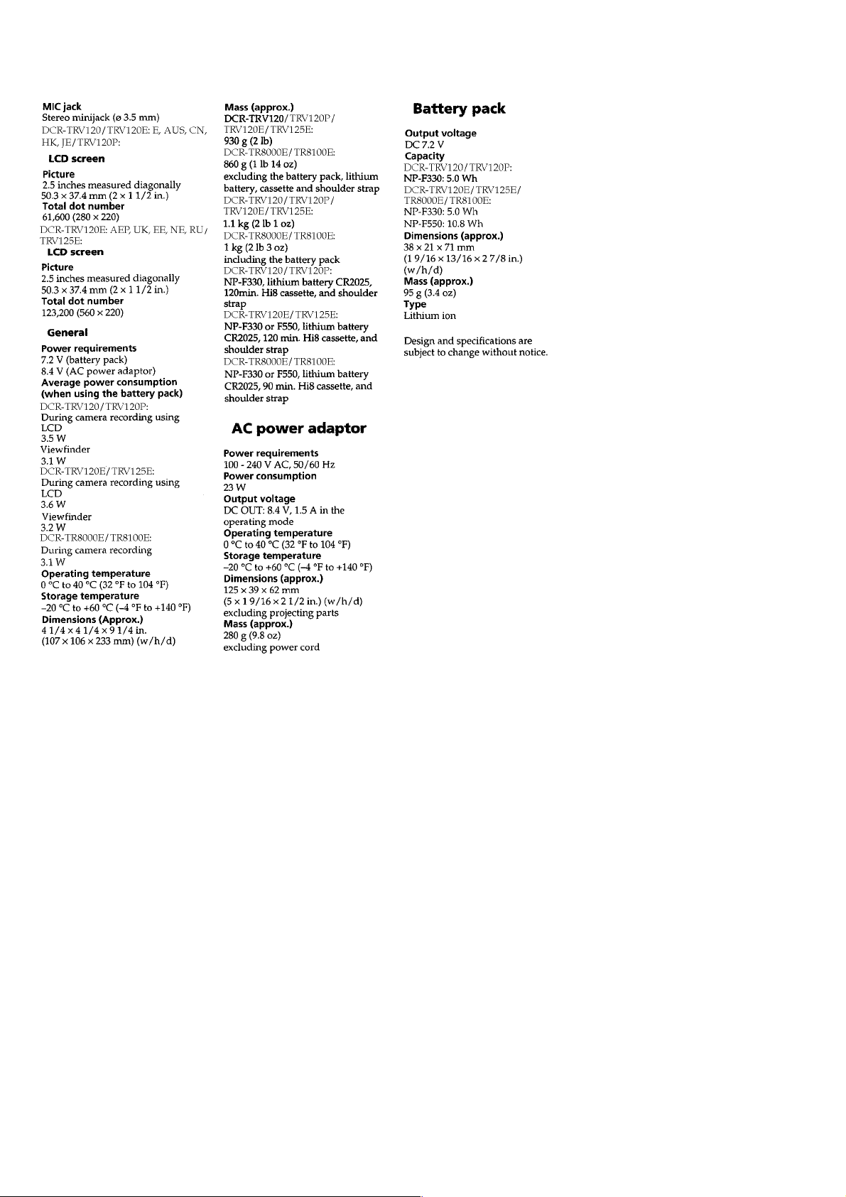
SPECIFICATIONS
For MECHANISM ADJUSTMENT, refer to
the “8mm Video MECHANICAL
ADJUSTMENT MANUAL
” (9-973-801-11).
– Continued on next page –
DIGITAL VIDEO CASSETTE RECORDER
SAFETY-RELATED COMPONENT WARNING!!
COMPONENTS IDENTIFIED BY MARK 0 OR DOTTED
LINE WITH MARK 0 ON THE SCHEMATIC DIAGRAMS
AND IN THE PARTS LIST ARE CRITICAL TO SAFE
OPERATION. REPLACE THESE COMPONENTS WITH
SONY PARTS WHOSE PART NUMBERS APPEAR AS
SHOWN IN THIS MANUAL OR IN SUPPLEMENTS PUBLISHED BY SONY.
SAFETY CHECK-OUT
After correcting the original service problem, perform the following
safety checks before releasing the set to the customer.
ATTENTION AU COMPOSANT AYANT RAPPORT
À LA SÉCURITÉ!
LES COMPOSANTS IDENTIFIÉS P AR UNE MARQUE 0
SUR LES DIAGRAMMES SCHÉMATIQUES ET LA LISTE
DES PIÈCES SONT CRITIQUES POUR LA SÉCURITÉ
DE FONCTIONNEMENT. NE REMPLACER CES COMPOSANTS QUE PAR DES PIÈCES SONY DONT LES
NUMÉROS SONT DONNÉS DANS CE MANUEL OU
DANS LES SUPPLÉMENTS PUBLIÉS PAR SONY.
1. Check the area of your repair for unsoldered or poorly-soldered connections. Check the entire board surface for solder
splashes and bridges.
2. Check the interboard wiring to ensure that no wires are
“pinched” or contact high-wattage resistors.
3. Look for unauthorized replacement parts, particularly transistors, that were installed during a previous repair. Point them
out to the customer and recommend their replacement.
4. Look for parts which, though functioning, show obvious signs
of deterioration. Point them out to the customer and recommend their replacement.
5. Check the B+ voltage to see it is at the values specified.
6. Flexible Circuit Board Repairing
• Keep the temperature of the soldering iron around 270 ˚C
during repairing.
• Do not touch the soldering iron on the same conductor of
the circuit board (within 3 times).
• Be careful not to apply force on the conductor when soldering or unsoldering.
– 2 –

Supplied accessories
Table for differences of function
Model
Destination
Color system
Digital zoom
CCD imager
MONITOR IN
VTR REC
LCD type
LCD (pixel)
CD board
CF board
FU board
PD board
SE board
• Abbreviation
AR : Argentina model
AUS : Australian model
BR : Brazilian model
CN : Chinese model
CND: Canadian model
EE : East European model
DCR-TRV120
US, CND, E, HK,
KR, BR, JE
DCR-TRV120P
E, AR
NTSC
450×
720H
a
a
TYPE S
61k
CD-242
CF-69
FU-138
PD-117
SE-104
HK : Hong Kong model
JE : Tourist model
KR : Korea model
NE : North European model
RU : Russian model
DCR-TRV120E
AEP, UK, EE,
NE, RU
PAL
100×
960H
a
×
TYPE S
123k
CD-244
CF-69
FU-138
PD-117
SE-104
E, AUS, HK,
CN, JE
PAL
450×
960H
a
a
TYPE C
61k
CD-244
CF-69
FU-138
PD-117
SE-104
DCR-TRV125E
AEP
PAL
125×
960H
a
×
TYPE S
123k
CD-244
CF-69
FU-138
PD-117
SE-104
DCR-TR8000E
AEP, UK, EE,
NE, RU
PAL
100×
960H
×
×
×
×
CD-269
CF-71
FU-143
×
SE-113
DCR-TR8100E
AEP
PAL
125×
960H
×
×
×
×
CD-269
CF-71
FU-143
×
SE-113
– 3 –

TABLE OF CONTENTS
Section Title Page Section Title Page
SERVICE NOTE................................................................... 7
1. Power Supply During Repairs....................................... 7
2. To Take Out a Cassette
When Not Eject (Force Eject) ....................................... 7
3. Note for Repair .............................................................. 8
SELF-DIAGNOSIS FUNCTION ........................................ 9
1. Self-diagnosis Function................................................. 9
2. Self-diagnosis Display................................................... 9
3. Service Mode Display ................................................... 9
3-1. Display Method .............................................................. 9
3-2. Switching of Backup No. ............................................... 9
3-3. End of Display ............................................................... 9
4. Self-diagnosis Code Table ............................................ 10
1. GENERAL
Checking Supplied Accessories............................................. 1-1
Quick Start Guide .................................................................... 1-1
Using This Manual ................................................................... 1-2
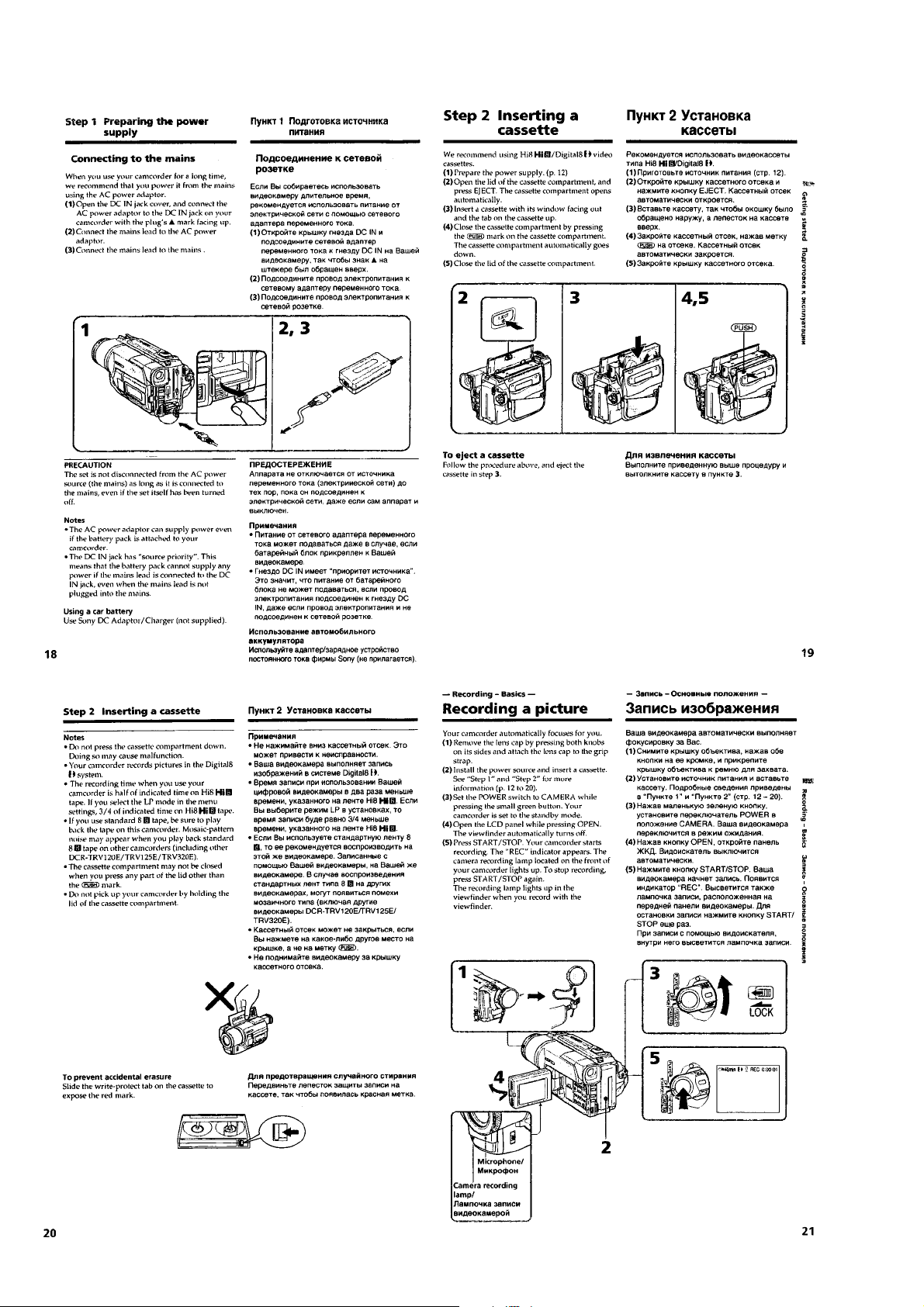
Step 1 Preparing the Power Supply........................................ 1-2
Step 2 Inserting a Cassette..................................................... 1-4
Recording a Picture................................................................. 1-4
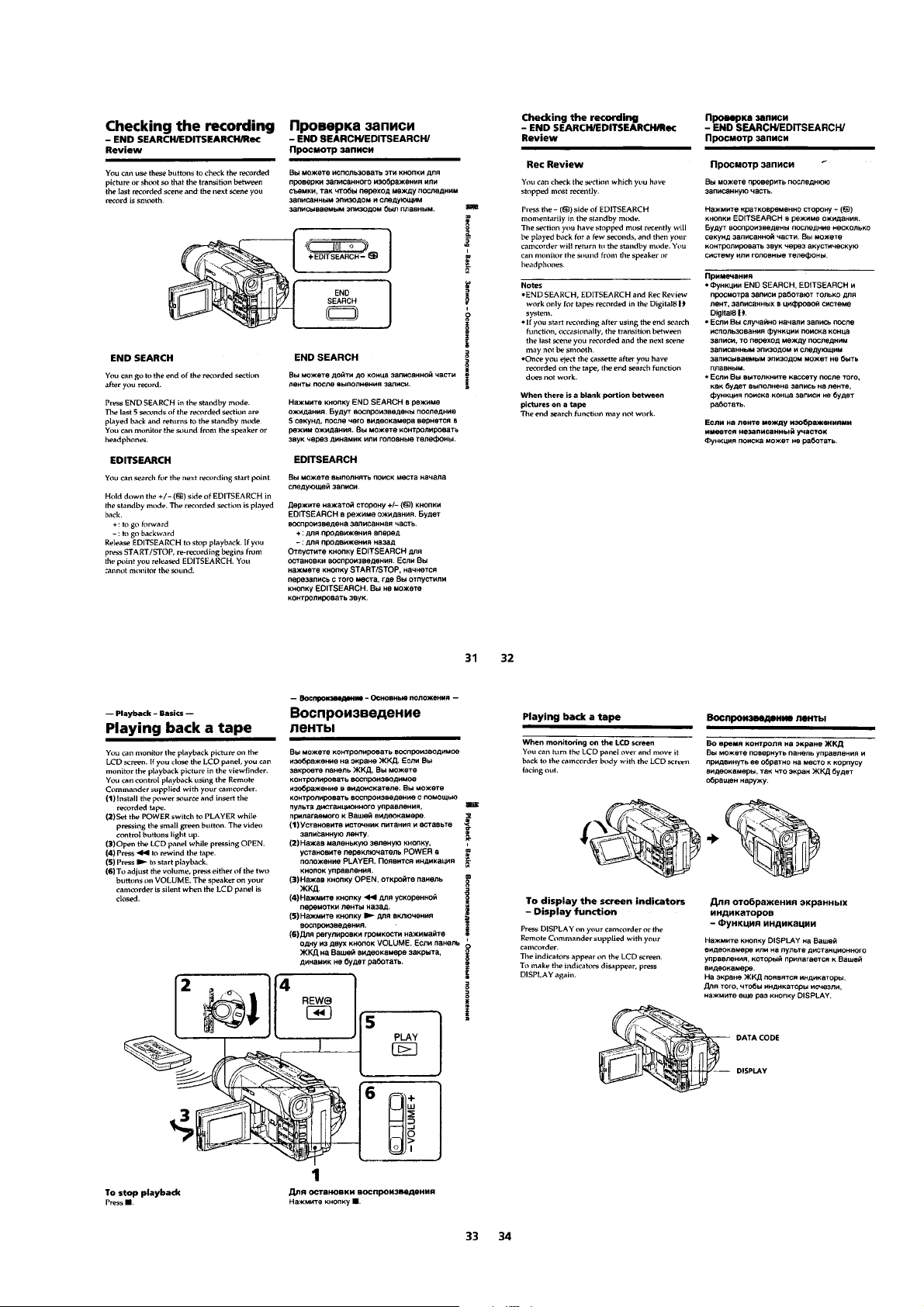
Checking the Recording
– END SEARCH/EDITSEARCH/Rec Review ......................... 1-7
Playing Back a Tape ................................................................ 1-7
Viewing the Recording on TV.................................................. 1-8
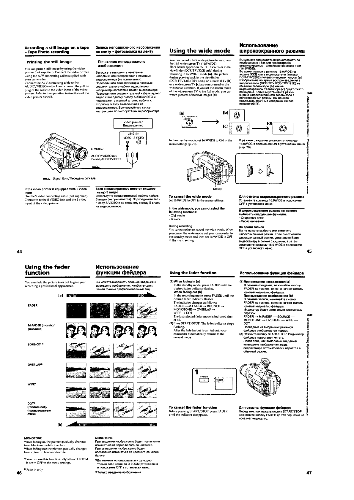
Recording a Still Image on a Tape
– T ape Photo Recording .......................................................... 1-9
Using the Wide Mode .............................................................. 1-10
Using the Fader Function........................................................ 1-10
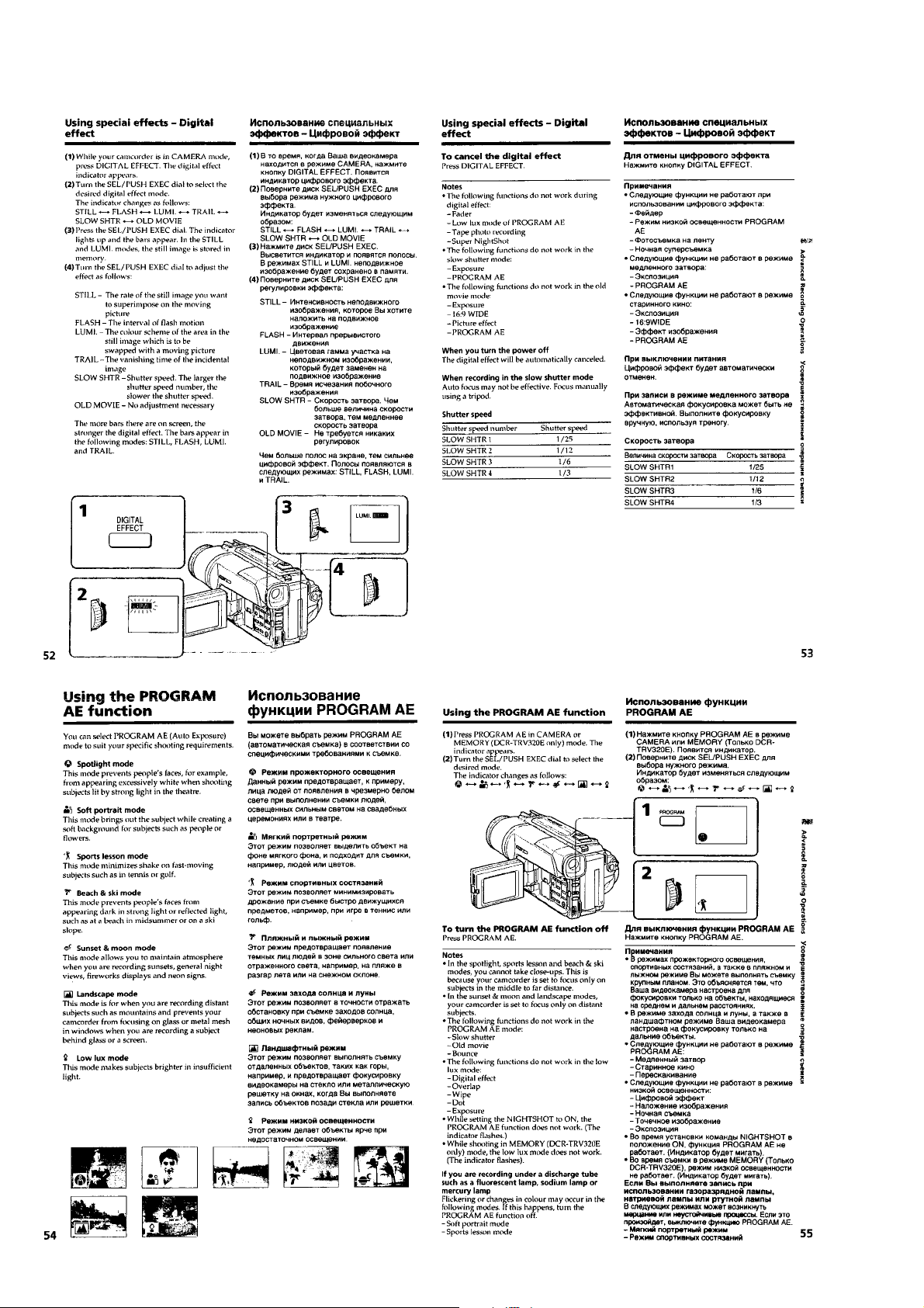
Using Special Effects
– Picture Effect ........................................................................ 1-11
Using Special Effects
– Digital Effect ......................................................................... 1-11
Using the PROGRAM AE Function......................................... 1-12
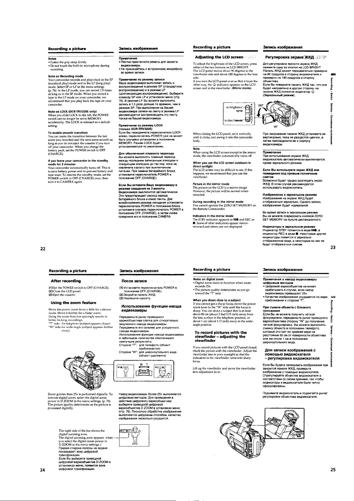
Adjusting the Exposure Manually............................................ 1-13
Focusing Manually................................................................... 1-13
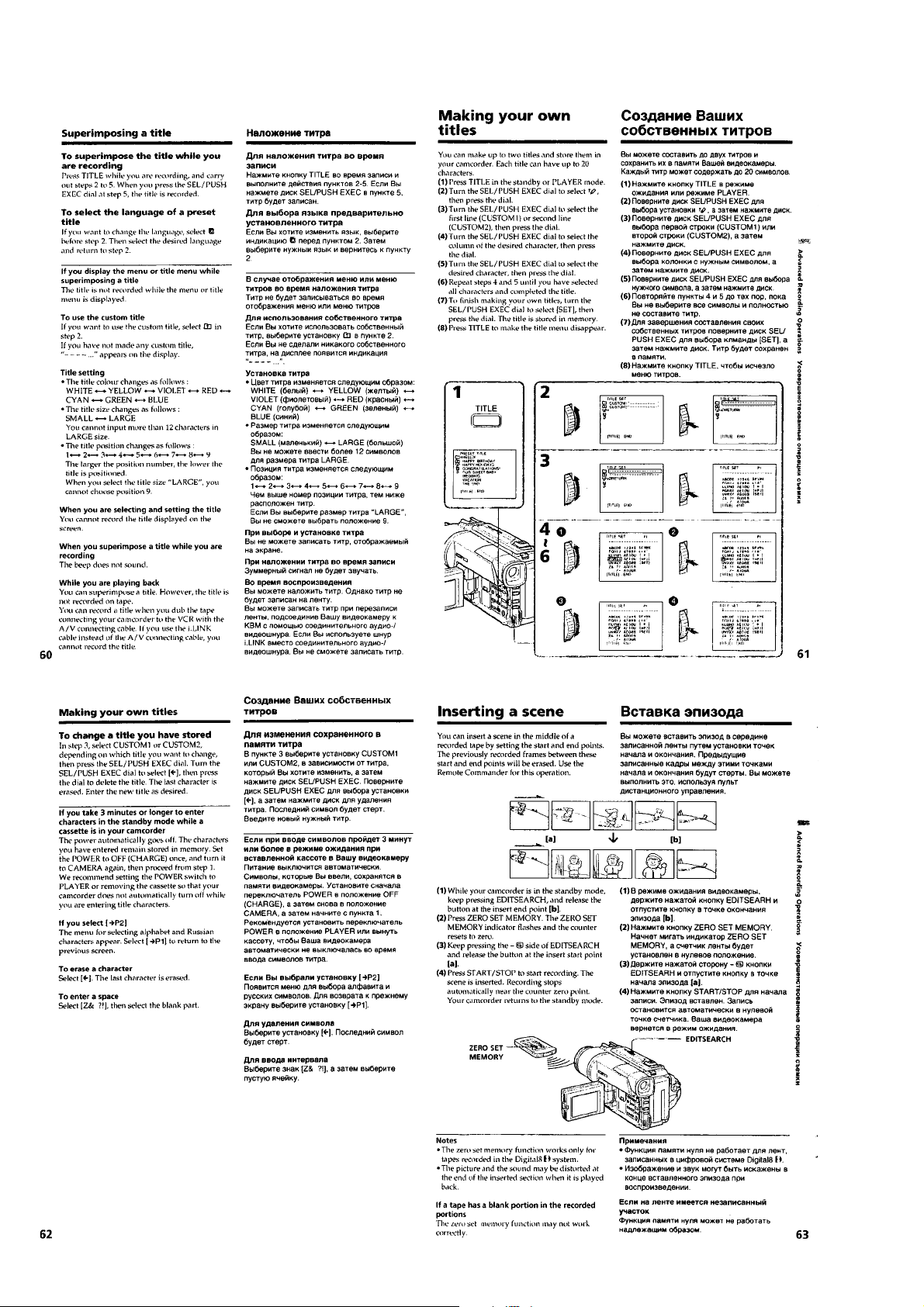
Superimposing a Title.............................................................. 1-13
Making Y our Own Titles ........................................................... 1-14
Inserting a Scene .................................................................... 1-14
Playing Back a Tape with Picture Effects................................ 1-15
Playing Back a Tape with Digital Effects ................................. 1-15
Enlarging Recorded Images
– PB ZOOM ............................................................................. 1-15
Quickly Locating a Scene Using the Zero Set
Memory Function..................................................................... 1-15
Searching a Recording by Date
– Date Search.......................................................................... 1-16
Searching for a Photo
– Photo Search/Photo Scan.................................................... 1-16
Dubbing a Tape........................................................................ 1-17
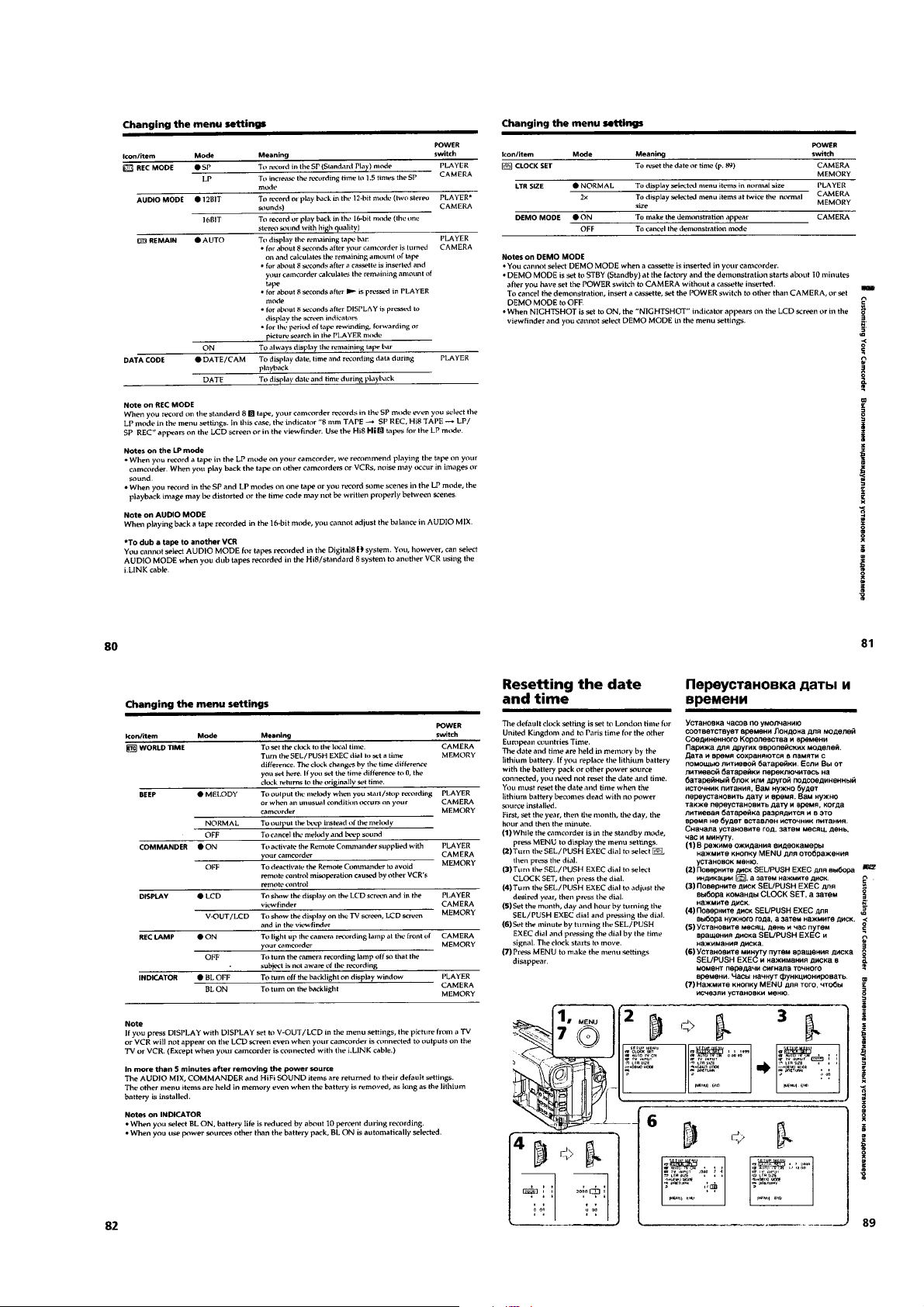
Changing the Menu Settings................................................... 1-18
Resetting the Date and Time .................................................. 1-19
Digital8 System, Recording and Playback.............................. 1-20
Changing the Lithium Battery in Your Camcorder................... 1-20
Troubleshooting ....................................................................... 1-21
Self-diagnosis Display ............................................................. 1-22
Warning Indicators and Messages.......................................... 1-22
Using Your Camcorder Abroad ................................................ 1-23
Maintenance Information and Precautions ............................. 1-23
Identifying the Parts and Controls........................................... 1-25
2. DISASSEMBLY
2-1. LCD Assembly, PD-117 Board (TRV model) ................ 2-2
2-2. Front Panel Assembly ................................................... 2-3
2-3. Cabinet (L) Assembly, Cassette Lid Assembly............. 2-3
2-4. Cabinet (R) Assembly ................................................... 2-4
2-5. CF-69 Board (TRV model) ............................................ 2-4
2-6. CF-71 Board (TR model)............................................... 2-4
2-7. EVF Block ...................................................................... 2-4
2-8. EVF Assembly ............................................................... 2-5
2-9. VF-129 Board , CRT Assembly..................................... 2-5
2-10. Battery Panel Assembly ................................................ 2-6
2-11. Cabinet (L) Assembly .................................................... 2-6
2-12. Lens Block ..................................................................... 2-6
2-13. Control Switch Block (FK-10000).................................. 2-6
2-14. FU-138/143 Board......................................................... 2-7
2-15. VC-235 Board................................................................ 2-7
2-16. Circuit Boards Location ................................................. 2-8
2-17. Flexible Boards Location............................................... 2-9
3. BLOCK DIAGRAMS
3-1. Overall Block Diagram 1................................................ 3-1
3-2. Overall Block Diagram 2................................................ 3-3
3-3. Overall Block Diagram 3................................................ 3-5
3-4. Power Block Diagram 1 ................................................. 3-7
3-5. Power Block Diagram 2 ................................................. 3-9
3-6. Power Block Diagram 3 ................................................. 3-11
4. PRINTED WIRING BOARDS AND
SCHEMATIC DIAGRAMS
4-1. Frame Schematic Diagrams.......................................... 4-3
Frame (1) Schematic Diagram...................................... 4-3
Frame (2) Schematic Diagram...................................... 4-5
4-2. Pr inted Wiring Boards and Schematic Diagrams ......... 4-7
CD-242 Printed Wiring Board and
Schematic Diagram ....................................................... 4-7
CD-244/269 Printed Wiring Board and
Schematic Diagram ....................................................... 4-9
VC-235 Printed Wiring Board........................................ 4-11
VC-235 (CAMERA PROCESSOR)
Schematic Diagram ....................................................... 4-15
VC-235 (Y/C PROCESSOR)
Schematic Diagram ....................................................... 4-17
VC-235 (LENS MOTOR DRIVE)
Schematic Diagram ....................................................... 4-19
VC-235 (VIDEO IN/OUT) Schematic Diagram ............. 4-21
VC-235 (BASE BAND INPUT)
Schematic Diagram ....................................................... 4-23
VC-235 (VIDEO/AUDIO DSP, D/A CONVERTER)
Schematic Diagram ....................................................... 4-25
VC-235 (DV INTERFACE, OSD)
Schematic Diagram ....................................................... 4-27
VC-235 (A/D CONVERTER, REC/PB AMP)
Schematic Diagram ....................................................... 4-29
VC-235 (Hi8/Std8 PB AMP) Schematic Diagram ......... 4-31
VC-235 (HI CONTROL) Schematic Diagram................ 4-33
VC-235 (Digital8 MECHANISM CONTROL)
Schematic Diagram ....................................................... 4-35
VC-235 (CAMERA CONTROL, Hi8/Std8 MECHANISM
CONTROL) Schematic Diagram ................................... 4-37
FP-38, FP-220, FP-221, FP-249, FP-355, FP-356,
VC-235 (SERVO) Schematic Diagram ........................ 4-39
FP-249, FP-355, FP-356 Printed Wiring Boards and
VC-235 (D/A CONVERTER) Schematic Diagram ........ 4-41
VC-235 (AUDIO IN/OUT) Schematic Diagram ............. 4-43
VC-235 (DC/DC CONVERTER)
Schematic Diagram ....................................................... 4-45
SE-104/113 Printed Wiring Board................................. 4-47
SE-104/113 Schematic Diagram................................... 4-49
FP-156, MI-37 Printed Wiring Boards........................... 4-51
FP-156, MI-37 (STEREO MIC AMP)
Schematic Diagram ....................................................... 4-55
MI-37 (IR TRANSMITTER) Schematic Diagram........... 4-57
CF-69 Printed Wiring Board.......................................... 4-59
MF-10000, CF-69 Schematic Diagram ......................... 4-63
MF-10000, CF-71 Schematic Diagram ......................... 4-65
CF-71 Printed Wiring Board.......................................... 4-67
FK-10000 Schematic Diagram...................................... 4-71
VF-129 Schematic Diagram .......................................... 4-73
PD-117 Printed Wiring Board........................................ 4-75
– 4 –

Section Title Page Section Title Page
PD-117 (RGB LCD DRIVER, TIMING GENERATOR)
Schematic Diagram ....................................................... 4-79
PR-10000, PD-117 (CG LCD DRIVER, BACK LIGHT)
Schematic Diagram ....................................................... 4-81
FU-138/143 Printed Wiring Board................................. 4-83
SS-10000, FU-138/143 Schematic Diagram ................ 4-85
4-3. Waveforms ..................................................................... 4-87
4-4. Parts Location ............................................................... 4-91
5. ADJUSTMENTS
1. Before Starting Adjustment ........................................... 5-1
1-1. Adjusting Items
when Replacing Main Parts and Boards ................. 5-2
5-1. Camera Section Adjustment ......................................... 5-4
1-1. Preparations Before Adjustment
(Camera Section) ..................................................... 5-4
1-1-1. List of Service Tools ................................................. 5-4
1-1-2. Preparations............................................................. 5-5
1-1-3. Precaution ................................................................ 5-8
1. Setting the Switch .................................................... 5-8
2. Order of Adjustments ............................................... 5-8
3. Subjects.................................................................... 5-8
1-2. Initialization of 7, 8, C, D, E, F Page Data ............... 5-9
1-2-1. Initialization of 8, C, D Page Data............................ 5-9
1. Initializing the 8, C, D Page Data............................. 5-9
2. Modification of 8, C, D Page Data ........................... 5-9
3. 8 Page Table............................................................. 5-9
4. C Page Table ............................................................ 5-10
5. D Page Table ............................................................ 5-11
1-2-2. Initialization of 7, E, F Page Data ............................ 5-12
1. Initializing the 7, E, F Page Data ............................. 5-12
2. Modification of 7, E, F Page Data ............................ 5-12
3. 7 Page Table............................................................. 5-12
4. E Page Table ............................................................ 5-13
5. F Page Table............................................................. 5-14
1-3. Camera System Adjustments .................................. 5-15
1. HALL Adjustment ..................................................... 5-15
2. Flange Back Adjustment (Using Minipattern Box)... 5-16
3. Flange Back Adjustment
(Using Flange Back Adjustment Chart Subject
More Than 500 m Away) .......................................... 5-17
3-1. Flange Back Adjustment (1)..................................... 5-17
3-2. Flange Back Adjustment (2)..................................... 5-17
4. Flange Back Check .................................................. 5-18
5. Optical Axis Adjustment ........................................... 5-19
6. Picture Frame Setting .............................................. 5-20
7. Color Reproduction Adjustment............................... 5-21
8. AWB & LV Standard Data Input ............................... 5-22
9. Auto White Balance Adjustment .............................. 5-22
10. White Balance Check............................................... 5-23
11. Angular Velocity Sensor Sensitivity Data Preset and
Steady Shot Check .................................................. 5-24
1-4. Monochrome Electronic Viewfinder
System Adjustments ................................................ 5-25
1-4-1. Horizontal Slant Check ............................................ 5-25
1-4-2. Centering Adjustment .............................................. 5-25
1-4-3. Focus Adjustment..................................................... 5-25
1-4-4. Aberration Adjustment ............................................. 5-26
1-4-5. Horizontal Amplitude Adjustment (VF-129 Board) .. 5-26
1-4-6. Vertical Amplitude Adjustment (VF-129 Board)....... 5-27
1-4-7. Brightness Adjustment (VF-129 Board)................... 5-27
1-4-8. Horizontal Amplitude, Vertical Amplitude,
Focus Check............................................................. 5-27
1-5. LCD System Adjustments
(DCR-TRV120/TRV120E/TRV120P/TRV125E) ....... 5-28
1. LCD Initial Data Input (1) ......................................... 5-28
2. LCD Initial Data Input (2) ......................................... 5-29
3. VCO Adjustment (PD-117 Board)............................ 5-29
4. RGB AMP Adjustment (PD-117 Board)................... 5-30
5. Contrast Adjustment (PD-117 Board)...................... 5-30
6. COM AMP Adjustment (PD-117 Board) .................. 5-31
7. V-COM Adjustment (PD-117 Board)........................ 5-31
8. White Balance Adjustment (PD-117 Board) ............ 5-32
5-2. MECHANISM SECTION ADJUSTMENT...................... 5-33
2-1. Hi8/Standard 8 mm Mode ........................................ 5-33
2-1-1. How to Enter Playback Mode Without Cassette ...... 5-33
2-1-2. Tape Path Adjustment .............................................. 5-33
1. Preparations for Adjustment .................................... 5-33
2-2. Digital8 Mode ........................................................... 5-34
2-2-1. How to Enter Record Mode Without Cassette......... 5-34
2-2-2. How to Enter Playback Mode Without Cassette ...... 5-34
2-2-3. Overall Tape Path Check.......................................... 5-34
1. Recording of the Tape Path Check Signal ............... 5-34
2. Tape Path Check ...................................................... 5-34
5-3. Video Section Adjustment............................................. 5-35
3-1. Preparations Before Adjustments ............................ 5-35
3-1-1. Equipment to Required ............................................ 5-35
3-1-2. Precautions on Adjusting ......................................... 5-36
3-1-3. Adjusting Connectors............................................... 5-37
3-1-4. Connecting the Equipment....................................... 5-37
3-1-5. Alignment Tape ......................................................... 5-38
3-1-6. Input/output Level and Impedance .......................... 5-39
3-2. System Control System Adjustment ........................ 5-40
1. Initialization of 7, 8, C, D, E, F Page Data ............... 5-40
2. Node Unique ID No. Input ........................................ 5-40
2-1. Input of Company ID ................................................ 5-40
2-2. Input of Serial No...................................................... 5-40
3. Battery End Adjustment (VC-235 Board) ................ 5-42
3-3. Servo and RF System Adjustments......................... 5-43
1. REEL FG Adjustment (VC-235 Board) .................... 5-43
2. PLL f0 & LPF f0 Pre-adjustment (VC-235 Board) ..... 5-43
3. Switching Position Adjustment (VC-235 Board)...... 5-44
4. AGC Center Level Adjustment (VC-235 Board) ...... 5-44
5. APC & AEQ Adjustment (VC-235 Board) ................ 5-45
6. PLL f0 & LPF f0 Final Adjustment
(VC-235 Board) ........................................................ 5-45
7. Hi8/standard 8 mm Switching Position Adjustment
(VC-235 Board) ........................................................ 5-46
8. CAP FG Duty Adjustment (VC-235 Board) ............. 5-46
3-4. Video System Adjustments ...................................... 5-47
3-4-1. Video System Adjustments ...................................... 5-47
1. 27 MHz/36 MHz Origin Oscillation Adjustment
(VC-235 Board)) ....................................................... 5-47
2. Chroma BPF f0 Adjustment (VC-235 Board) ........... 5-47
3. S VIDEO OUT Y Level Adjustment
(VC-235 Board) ........................................................ 5-48
4. S VIDEO OUT Chroma Level Adjustment
(VC-235 Board) ........................................................ 5-48
5. VIDEO OUT Y, Chroma Level Check
(VC-235 Board) ........................................................ 5-49
6. Hi8/standard 8 mm AFC f0 Adjustment
(VC-235 Board) (Using Digital Voltmeter)................ 5-49
7. Hi8/standard 8 mm AFC f0 Adjustment
(VC-235 Board) (Auto Adjustment).......................... 5-49
3-5. IR T ransmitter Adjustments ...................................... 5-50
1. IR Video Carrier Frequency Adjustment
(MI-37 Board) ........................................................... 5-50
2. IR Video Deviation Adjustment (MI-37 Board)......... 5-50
3. IR Audio Deviation Adjustment (MI-37 Board) ........ 5-51
3-6. Audio System Adjustments ...................................... 5-52
1. Hi8/standard 8 mm AFM BPF f0 Adjustment
(VC-235 Board) ........................................................ 5-52
2. Hi8/standard 8 mm AFM 1.5 MHz Deviation
Adjustment (VC-235 Board)..................................... 5-53
3. Hi8/standard 8 mm AFM 1.7 MHz
Deviation Adjustment (VC-235 Board) .................... 5-53
4. Digital8 Playback Level Check................................. 5-53
5. Overall Level Characteristics Check........................ 5-53
6. Overall Distortion Check .......................................... 5-53
7. Overall Noise Level Check....................................... 5-54
8. Overall Separation Check ........................................ 5-54
5-4. SERVICE MODE ........................................................... 5-55
4-1. Adjustment Remote Commander ............................ 5-55
1. Using the Adjustment Remote Commander ............ 5-55
2. Precautions Upon Using the Adjustment Remote
Commander.............................................................. 5-55
4-2. Data Process............................................................ 5-56
– 5 –

Section Title Page
4-3. Service Mode ........................................................... 5-57
1. Setting the Test Mode .............................................. 5-57
2. Emergence Memory Address .................................. 5-57
2-1. C Page Emergence Memory Address ..................... 5-57
2-2. F Page Emergence Memory Address...................... 5-58
2-3. EMG Code (Emergency Code) ................................ 5-58
2-4. MSW Code ............................................................... 5-59
3. Bit Value Discrimination ........................................... 5-60
4. Input/output Check ................................................... 5-60
5. LED, LCD (Display Window) Check......................... 5-60
6. Record of Use Check ............................................... 5-61
7. Switch Check (1) ...................................................... 5-61
8. Switch Check (2) ...................................................... 5-62
9. Headphone Jack Check ........................................... 5-62
6. REPAIR PARTS LIST
6-1. Exploded Views ............................................................. 6-1
6-1-1. Front Panel Section .................................................. 6-1
6-1-2. Cabinet (R) Section
(TRV120/TRV120E/TRV120P/TRV125E) ................ 6-2
6-1-3. Cabinet (R) Section (TR8000E/TR8100E) .............. 6-3
6-1-4. EVF Block Section ................................................... 6-4
6-1-5. LCD Assembly Section
(TRV120/TRV120E/TRV120P/TRV125E) ................ 6-5
6-1-6. Cabinet (L) Section .................................................. 6-6
6-1-7. Lens Block Section................................................... 6-7
6-1-8. Main Board Section.................................................. 6-8
6-1-9. Cassette Compar tment Assembly ........................... 6-9
6-1-10. LS Chassis Assembly .............................................. 6-10
6-1-11. Mechanism Chassis Assembly ................................ 6-11
6-2. Electr ical Parts List ....................................................... 6-12
* The optical axis frame is shown on page 251.
The color reproduction frame is shown on page 252.
The parts reference sheet is shown on page 253.
– 6 –
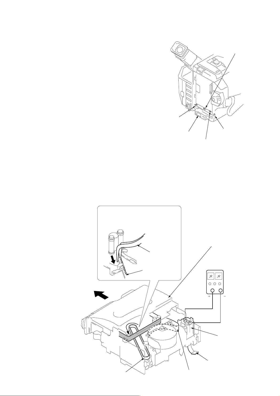
SERVICE NOTE
7 Pull the timing belt in the direction of the
arrow with a pincette while pressing
the cassette lid (take care not to damage)
to adjust the bending of a tape.
8 Let go your hold the cassette
lid and rise the cassette
compartment to take out a cassette.
Pincette
Timing belt
Timing belt
Press the cassette lid to rise
the cassette compartment
[DC power supply]
(+5V)
Adjust the bending of a tape
Disconnect CN4401
of VC-235 board.
Loading motor
1. POWER SUPPLY DURING REPAIRS
In this unit, about 10 seconds after power is supplied (8.4 V) to the
battery terminal using the service power cord (J-6082-223-A), the
power is shut off so that the unit cannot operate.
This following two methods are available to prevent this. Take
note of which to use during repairs.
Method 1.
Connect the servicing remote commander RM-95 (J-6082-053-B)
to the LANC jack, and set the remote commander switch to the
“ADJ” side.
Method 2.
Press the battery switch of the battery terminal using adhesive tape,
etc.
Battery switch
Battery terminal 3
Method 3.
DC IN terminal
Use the DC IN terminal. (Use the AC power adaptor.)
Battery SIG terminal
2. TO TAKE OUT A CASSETTE WHEN NOT EJECT (FORCE EJECT)
1 Refer to 2-2 to remove the front panel assembly.
2 Refer to 2-4 to remove the cabinet (R) assembly.
3 Refer to 2-10 to remove the battery panel assembly.
4 Refer to 2-11 to remove the cabinet (L) assembly.
5 Disconnect CN4401 of VC-235 board.
6 Add +5 V from the DC POWER SUPPLY and unload with a
pressing the cassette lid.
Battery terminal #
– 7 –

3. NOTE FOR REPAIR
Make sure that the flat cable and flexible board are not cracked of
bent at the terminal.
Do not insert the cable insufficiently nor crookedly.
Cut and remove the part of gilt
which comes off at the point.
(Take care that there are some
pieces of gilt left inside)
When remove a connector, don’t pull at wire of connector.
Be in danger of the snapping of a wire.
When installing a connector, don’t press down at wire of connector.
Be in danger of the snapping of a wire.
– 8 –
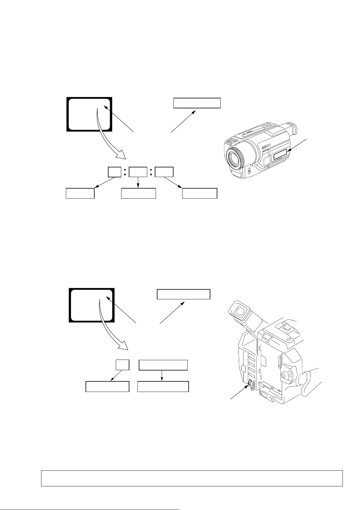
SELF-DIAGNOSIS FUNCTION
1. Self-diagnosis Function
When problems occur while the unit is operating, the self-diagnosis function starts working, and displays on the viewfinder or Display window what to do. This function consists of two display;
self-diagnosis display and service mode display.
Details of the self-diagnosis functions are provided in the Instruction manual.
Viewfinder Display window
C : 3 1 : 1 1
Repaired by:
C : Corrected by customer
H : Corrected by dealer
E : Corrected by service
engineer
Blinks at 3.2Hz
C
Indicates the appropriate
step to be taken.
E.g.
31 ....Reload the tape.
32 ....Turn o n power again.
3 1
Block
1 1
C : 3 1 : 11
Refer to page 10 and 11.
Self-diagnosis Code Table.
2. Self-diagnosis Display
When problems occur while the unit is operating, the counter of
the viewfinder or Display window sho ws a 4-digit display consisting of an alphabet and numbers, which blinks at 3.2 Hz. This 5character display indicates the “repaired by:”, “block” in which
the problem occurred, and “detailed code” of the problem.
Display window
Detailed Code
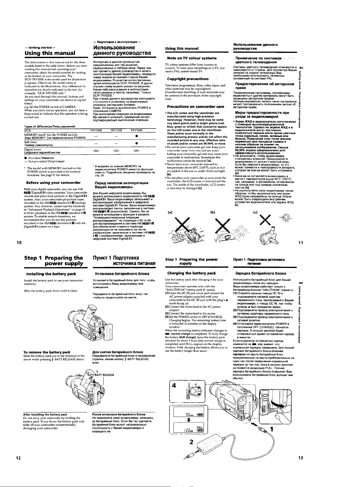
3. Service Mode Display
The service mode display shows up to six self-diagnosis codes shown in the past.
3-1. Display Method
While pressing the “STOP” key, set the switch from OFF to “VTR or PLAYER”, and continue pressing the “STOP” key for 5 seconds
continuously. The service mode will be displayed, and the counter will show the backup No. and the 5-character self-diagnosis codes.
Viewfinder
[3] C : 3 1 : 1 1
Lights up
[3]
Backup No.
Order of previous errors
C : 3 1 : 1 1
Self-diagnosis Codes
3-2. Switching of Backup No.
By rotating the control dial, past self-diagnosis codes will be shown in order. The backup No. in the [] indicates the order in which the
problem occurred. (If the number of problems which occurred is less than 6, only the number of problems which occurred will be shown.)
[1] : Occurred first time [4] : Occurred fourth time
[2] : Occurred second time [5] : Occurred fifth time
[3] : Occurred third time [6] : Occurred the last time
Display window
3 C : 3 1 : 11
Control dial
3-3. End of Display
Turning OFF the power supply will end the service mode display.
Note: The “self-diagnosis display” data will be backed up by the coin-type lithium battery (CF-69/71 board BH001). When
this coin-type lithium battery is disconnected, the “self-diagnosis display” data will be lost by initialization.
– 9 –

4. Self-diagnosis Code Table
Self-diagnosis Code
Repaired by:
C
C
C
C
C
C
C
C
C
C
C
C
C
C
C
C
C
C
C
C
C
C
C
C
C
C
C
C
C
Block
Function
21
22
23
31
31
31
31
31
31
31
31
31
31
31
31
31
32
32
32
32
32
32
32
32
32
32
32
32
32
Detailed
Code
00
00
00
10
11
20
21
22
23
30
31
40
41
42
43
44
10
11
20
21
22
23
30
31
40
41
42
43
44
Symptom/State
Condensation.
Video head is dirty.
Non-standard battery is used.
LOAD direction. Loading does not
complete within specified time
UNLOAD direction. Loading does not
complete within specified time
T reel side tape slacking when unloading
S reel
side tape slacking when unloading
T reel fault.
S reel fault.
FG fault when starting capstan.
FG fault during normal capstan operations.
FG fault when starting drum.
PG fault when starting drum.
FG fault during normal drum operations.
PG fault during normal drum operations.
Phase fault during normal drum operations.
LOAD direction loading motor time-
out.
UNLOAD direction loading motor
time-out.
T reel side tape slacking when
unloading.
S reel side tape slacking when
unloading.
T reel fault.
S reel fault.
FG fault when starting capstan.
FG fault during normal capstan
operations.
FG fault when starting drum.
PG fault when starting drum.
FG fault during normal drum
operations.
PG fault during normal drum
operations.
Phase fault during normal drum
operations.
Correction
Remove the cassette, and insert it again after one hour.
Clean with the optional cleaning cassette.
Use the InfoLITHIUM battery.
Load the tape again, and perform operations from the beginning.
Load the tape again, and perform operations from the beginning.
.
Load the tape again, and perform operations from the beginning.
.
Load the tape again, and perform operations from the beginning.
Load the tape again, and perform operations from the beginning.
Load the tape again, and perform operations from the beginning.
Load the tape again, and perform operations from the beginning.
Load the tape again, and perform operations from the beginning.
Load the tape again, and perform operations from the beginning.
Load the tape again, and perform operations from the beginning.
Load the tape again, and perform operations from the beginning.
Load the tape again, and perform operations from the beginning.
Load the tape again, and perform operations from the beginning.
Remove the battery or power cable, connect, and perform
operations from the beginning.
Remove the battery or power cable, connect, and perform
operations from the beginning.
Remove the battery or power cable, connect, and perform
operations from the beginning.
Remove the battery or power cable, connect, and perform
operations from the beginning.
Remove the battery or power cable, connect, and perform
operations from the beginning.
Remove the battery or power cable, connect, and perform
operations from the beginning.
Remove the battery or power cable, connect, and perform
operations from the beginning.
Remove the battery or power cable, connect, and perform
operations from the beginning.
Remove the battery or power cable, connect, and perform
operations from the beginning.
Remove the battery or power cable, connect, and perform
operations from the beginning.
Remove the battery or power cable, connect, and perform
operations from the beginning.
Remove the battery or power cable, connect, and perform
operations from the beginning.
Remove the battery or power cable, connect, and perform
operations from the beginning.
– 10 –

Self-diagnosis Code
Repaired by:
E
E
E
E
Block
Function
61
61
62
62
Detailed
Code
00
10
00
01
Symptom/State
Difficult to adjust focus
(Cannot initialize focus.)
Zoom operations fault
(Cannot initialize zoom lens.)
Handshake correction function does not
work well. (With pitch angular velocity
sensor output stopped.)
Handshake correction function does not
work well. (With yaw angular velocity
sensor output stopped.)
Correction
Inspect the lens block focus reset sensor (Pin 9 of CN1551 of
VC-235 board) when focusing is performed when the control dial
is rotated in the focus manual mode and the focus motor drive circuit
(IC1553 of VC-235 board) when the focusing is not performed.
Note: Use the remote commander RM-95 only for the model without the
focus dial.
Inspect the lens block zoom reset sensor (Pin 0 of CN1551 of
VC-235 board) when zooming is performed when the zoom lens is
operated and the zoom motor drive circuit (IC1553 of VC-235
board) when zooming is not performed.
Inspect pitch angular velocity sensor (SE201 of SE-104/113
board) peripheral circuits.
Inspect yaw angular velocity sensor (SE202 of SE-104/113
board) peripheral circuits.
– 11 –

DCR-TRV120/TRV120E/TRV120P/TRV125E/
SECTION 1
GENERAL
TR8000E/TR8100E
This section is extracted from DCR-TR V120E/
TRV125E/TRV320E instr uction manual.
1-1
1-2

1-3
1-4
1-5

1-6
1-7

1-8

1-9
1-10

1-11
1-12

1-13
1-14

1-15

1-16

1-17

1-18
1-19
 Loading...