

Page 1
DCR-TRV103/TRV110/TRV110E/TRV110P/TRV203/TRV210/
TRV210E/TRV310/TRV310E/TRV310P/TRV315
DCR-TR7000/TR7000E/TR7100E
RMT-814
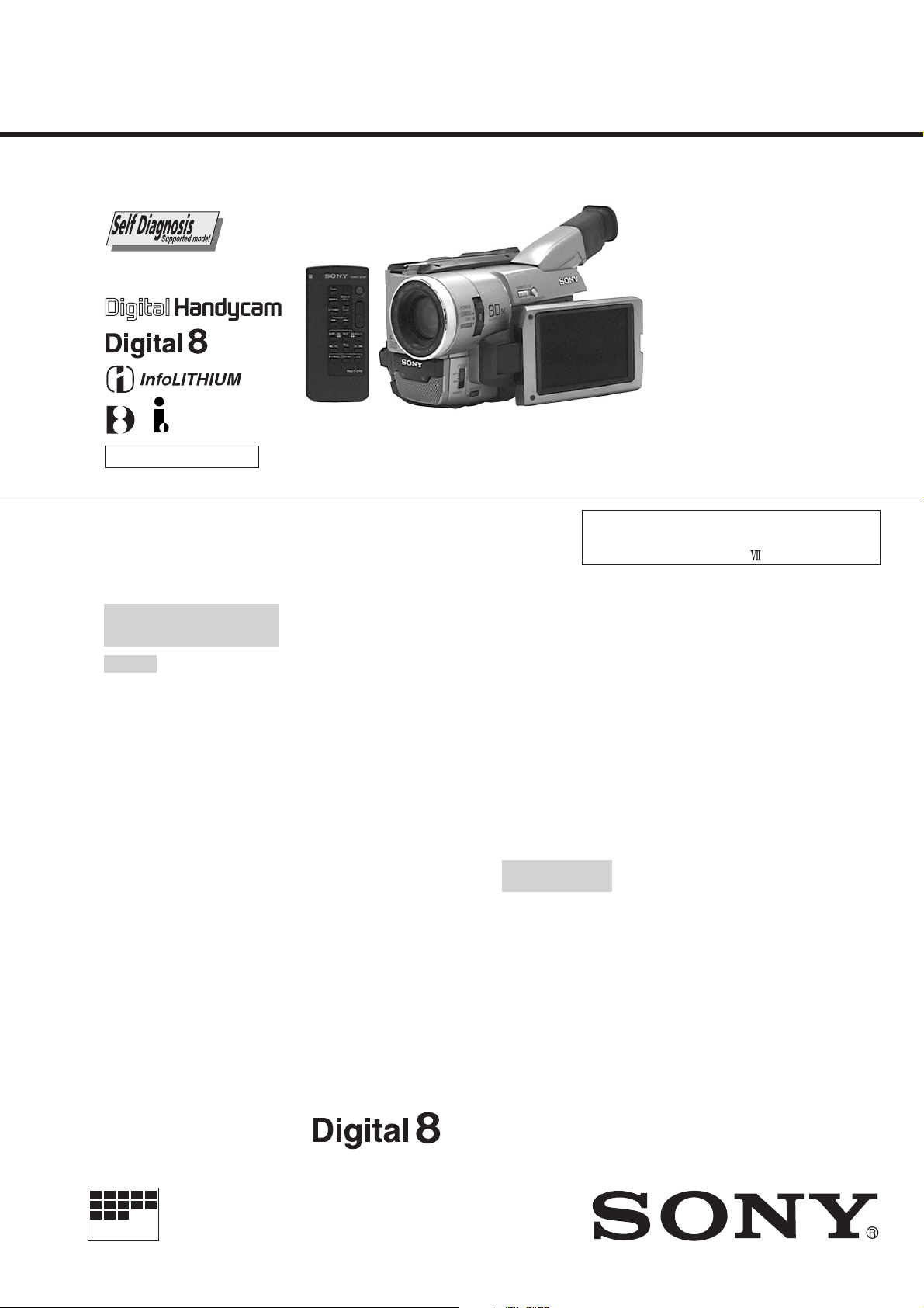
SERVICE MANUAL
Ver 1.3 2001. 01
Photo: DCR-TRV310E
B800 MECHANISM
NTSC MODEL : DCR-TRV103/TRV110/TRV110P/TRV203/TRV210/
TRV310/TRV310P/TRV315/TR7000
PAL MODEL : DCR-TRV110E/TRV210E/TRV310E/TR7000E/TR7100E
SPECIFICATIONS
Video camera
recorder
System
Video recording system
2 rotary heads
Helical scanning system
Audio recording system
Rotary heads, PCM system
Quantization: 12 bits (Fs 32 kHz,
stereo 1, stereo 2), 16 bits
(Fs 48 kHz, stereo)
Video signal
DCR-TRV103/TRV110/TRV110P/
TRV203/TRV210/TRV310/
TRV310P/TR
NTSC color, EIA standards
TRV110E/TRV210E/TRV310E/
TR7000E/TR7100E:
PAL color , CCIR standards
Recommended cassette
Hi8 video cassette
Recording/playback time
DCR-TRV103/TRV110/TRV110P/
TRV203/TRV210/TRV310/TRV310P/
TRV315/TR7000: (using 120 min.
cassette)
1 hours
DCR-TRV110E/TRV210E/TRV310E/
TR7000E/TR7100E:
cassette)
1 hours
Fastforward/rewind time DCRTRV103/TRV110/TRV110P/TRV203/
TRV210/TRV310/TRV310P/TRV315/
TR7000: (using 120 min. cassette)
DCR-TRV110E/TRV210E/TRV310E/
TR7000E/TR7100E:
cassette)
Approx. 8 min.
V315/TR7000:
(using 90 min.
(using 90 min.
Image device
1/4 inch CCD (Charge Coupled
Device)
DCR-TRV103/TRV110/TRV110P/
TRV203/TRV210/TRV310/
TRV310P/TRV315/TR7000:
Approx. 460,000 pixels
(Effective: Approx. 290,000 pixels)
DCR-TRV1 10E/TR V210E/
TRV310E/TR7000E/TR7100E:
Approx. 800,000 pixels
(Effective: Approx. 400,000 pixels)
Viewfinder
Electronic viewfinder
DCR-TRV315/TR7000/TR7000E/
TR7100E:
Monochrome
DCR-TRV103/TRV110/TRV110E/
TRV110P/TRV203/TRV210/
TRV210E/TRV310/TRV310E/
TRV310P:
Color
Lens
Combined power zoom lens
Filter diameter 1 7/16 in. (37 mm)
20× (Optical),
DCR-TRV103/TRV110/TRV110E:
EE, NE, RU/TRV110P/TRV203/
TRV210/TRV210E: CN/TRV310/
TRV310E/TRV310P: E, HK,
AUS, CN, JE/TRV315/TR7000:
360× (Digital)
DCR-TRV110E: AEP, UK/TRV210E:
AEP, UK/TRV310E: AEP, UK/
TR7000E/TR7100E:
80× (Digital)
Focal length
5/32 - 2 7/8 in. (3.6 - 72 mm)
When converted to a 35 mm still
camera
1 5/8 - 32 3/8 in. (41 - 820 mm)
Color temperature
Auto
Minimum illumination
DCR-TRV103/TRV110/TRV110P/
TRV203/TRV210/TRV310/
TRV310P/TRV315/TR7000:
1.0 lux (F 1.4)
DCR-TRV110E/TRV210E/
TRV310E/TR7000E/TR7100E:
3 lux (F 1.4)
0 lux (in the NightShot mode)*
* Objects unable to be seen due to
the dark can be shot with
infrared lighting
Input and output
connectors
DCR-TRV103/TRV110/TRV110E: E,
HK, AUS, CN, JE/TRV110P/TRV203/
TRV210/TRV210E: CN/TRV310/
TRV310E: E, HK, AUS, CN, JE/
TRV310P/TRV315/TR7000:
S video input/output
DCR-TRV110E: AEP, UK, EE, NE,
RU/TRV210E: AEP, UK/TRV310E:
AEP, UK/TR7000E/TR7100E:
S video output
4-pin mini DIN
Luminance signal: 1 Vp-p,
75 ohms, unbalanced
DIGITAL VIDEO CAMERA RECORDER
DCR-TRV103/TRV110/TRV210/TRV310/TRV315/TR7000
DCR-TRV103/TRV110/TRV203/TRV210/TRV315/TR7000
Canadian Model
DCR-TRV110/TRV110E/TRV110P/
TRV310/TRV310E/TRV310P
US Model
E Model
Hong Kong Model
DCR-TRV110/TRV110E/TRV310/TRV310E
DCR-TRV110E/TRV210E/TRV310E/
DCR-TRV110E/TRV210E/TRV310E/TR7000E
DCR-TRV110E/TRV310/TRV310E
DCR-TRV110E/TRV210E/TRV310E
AEP Model
TR7000E/TR7100E
UK Model
Tourist Model
Australian Model
DCR-TRV110E/TRV310E
Brazilian Model
DCR-TRV110
Chinese Model
East European Model
North European Model
Russian Model
DCR-TRV110E
Taiwan Model
DCR-TRV310
For MECHANISM ADJUSTMENT, refer to
the “8mm Video MECHANICAL
ADJUSTMENT MANUAL
DCR-TRV103/TRV110/TRV110P/
TRV203/TRV210/TRV310/
TRV310P/TRV315/TR7000:
Chrominance signal: 0.286 Vp-p,
DCR-TRV110E/TRV210E/
TRV310E/TR7000E/TR7100E:
Chrominance signal: 0.3 Vp-p
75 ohms, unbalanced
DCR-TRV103/TRV110/TRV110E: E,
HK, AUS, CN, JE/TRV110P/TRV203/
TRV210/TRV210E: CN/TRV310/
TRV310E: E, HK, AUS, CN, JE/
TRV310P/TRV315/TR7000:
Video input/output
DCR-TRV110E: AEP, UK, EE, NE,
RU/TRV210E: AEP, UK/TRV310E:
AEP, UK/TR7000E/TR7100E:
Video output
Phono jack, 1 Vp-p, 75 ohms,
unbalanced
DCR-TRV103/TRV110/TRV110E: E,
HK, AUS, CN, JE/TRV110P/TRV203/
TRV210/TRV210E: CN/TRV310/
TRV310E: E, HK, AUS, CN, JE/
TRV310P/TRV315/TR7000:
Audio input/output
DCR-TRV110E: AEP, UK, EE, NE,
RU/TRV210E: AEP, UK/TRV310E:
AEP, UK/TR7000E/TR7100E:
Audio output
Phono jacks (2: stereo L and R)
327 mV, (at output impedance
47 kilohms) impedance less than
2.2 kilohms
RFU DC OUT
Special minijack, DC 5V
” (9-973-801-11).
MICROFILM
Page 2

DCR-TRV103/TRV110/TRV110E: E,
HK, AUS, CN, JE/TRV110P/TRV203/
TRV210/TRV210E: CN/TRV310/
TRV310E: E, HK, AUS, CN, JE/
TRV310P/TRV315/TR7000:
DV input/output
DCR-TRV110E: AEP, UK, EE, NE,
RU/TRV210E: AEP, UK/TRV310E:
AEP, UK/TR7000E/TR7100E:
DV output
4-pin connector
Headphone jack
Stereo minijack (ø 3.5 mm)
LANC control jack
Stereo mini-minijack (ø 2.5 mm)
MIC jack
Minijack, 0.388 mV low impedance
with 2.5 to 3.0 V DC, output
impedance 6.8 kilohms (ø 3.5 mm)
Stereo type
LCD screen
Picture
DCR-TRV103/TRV110/TRV110E/
TRV110P:
2.5 inches measured diagonally
2 × 1 1/2 in. (50.3 × 37.4 mm)
DCR-TRV203/TRV210/TRV210E/
TRV315:
3 inches measured diagonally
2 3/8 × 1 3/4 in. (59.5 × 43.2 mm)
DCR-TRV310/TRV310E/TRV310P:
3.5 inches measured diagonally
2 7/8 × 2 in. (72.4 × 50.4 mm)
Total dot number
DCR-TRV103/TRV110/TRV110E/
TRV110P:
61,380 (279 × 220)
DCR-TRV203/TRV210/TRV210E/
TRV315:
89,622 (383 × 234)
DCR-TRV310/TRV310E/TRV310P:
105,380 (479 × 220)
General
Power requirements
7.2 V (battery pack)
8.4 V (AC power adaptor)
Average power consumption
(when using the battery pack)
During camera recording using
LCD
DCR-TRV103/TRV110/TRV110P:
3.5 W
DCR-TRV110E: 3.6 W
DCR-TRV203/TRV210/TRV210E/
TRV315: 3.9 W
DCR-TRV310/TRV310E/TRV310P:
4.2 W
Viewfinder
DCR-TRV110E/TRV203/TRV210/
TRV210E/TRV310/TRV310E/
TRV310P: 3.2 W
DCR-TRV103/TRV110/TRV110P/
TRV315: 3.1 W
During camera recording
DCR-TR7000/TR7000E/TR7100E:
3.1 W
Operating temperature
32 °F to 104 °F (0 °C to 40 °C)
Storage temperature
–4 °F to +140 °F (–20 °C to +60 °C)
Dimensions (Approx.)
DCR-TRV103/TRV110/TRV110E/
TRV110P:
4 × 4 1/4 × 8 5/8 in.
(101 × 107 × 217 mm) (w/h/d)
DCR-TRV203/TRV210/TRV210E/
TRV310/TRV310E:
4 3/8 × 4 1/4 × 8 5/8 in.
(108 × 107 × 217 mm) (w/h/d)
DCR-TRV315:
4 3/8 × 4 1/4 × 7 3/4 in.
(108 × 106 × 195 mm) (w/h/d)
DCR-TR7000/TR7000E/TR7100E:
4 × 4 1/4 × 7 3/4 in.
(101 × 106 × 195 mm) (w/h/d)
Mass (approx.)
DCR-TRV103/TRV110/TRV110E/
TRV110P:
1 lb 15 oz (890 g)
DCR-TRV203/TRV210/TRV210E/
TRV315:
2 lb (930 g)
DCR-TRV310/TRV310E:
2 lb 1 oz (960 g)
DCR-TR7000/TR7000E/TR7100E:
1 lb 11 oz (790 g)
excluding the battery pack, lithium
battery, cassette and shoulder
strap
DCR-TRV203/TRV210/TRV210E/
TRV310/TRV310E/TRV310P/
TRV315:
2 lb 6 oz (1.1 kg)
DCR-TRV103/TRV110/TRV110E/
TRV110P:
2 lb 3 oz (1 kg)
DCR-TR7000/TR7000E/TR7100E:
1 lb 11 oz (790 g)
including the battery pack
NP-F330, lithium battery CR2025,
120 min. cassette
(DCR-TRV103/TRV110/TRV110P/
TRV203/TRV210/TRV310/
TRV310P/TRV315/TR7000), 90 min.
cassette (DCR-TRV110E/TRV210E/
TRV310E/TR7000E/TR7100E)
and shoulder strap
Supplied accessories
See page 3.
AC power adaptor
Power requirements
100 - 240 V AC, 50/60 Hz
Power consumption
23 W
Output voltage
DC OUT: 8.4 V, 1.5 A in operating
mode
Operating temperature
32 °F to 104 °F (0 °C to 40 °C)
Storage temperature
–4 °F to +140 °F (–20 °C to +60 °C)
Dimensions (approx.)
5 × 1 9/16 × 2 1/2 in.
(125 × 39 × 62 mm) (w/h/d)
excluding projecting parts
Mass (approx.)
9.8 oz (280 g)
excluding power cord
Cord length (approx.)
AC power cord: 6.6 feet (2 m)
Connecting cord: 5.2 feet (1.6 m)
Design and specifications are
subject to change without notice.
• Abbreviation
EE : East European model
NE : North European model
RU : Russian model
HK : Hong Kong model
AUS : Australian model
CN : Chinese model
JE : Tourist model
— 2 —
Page 3
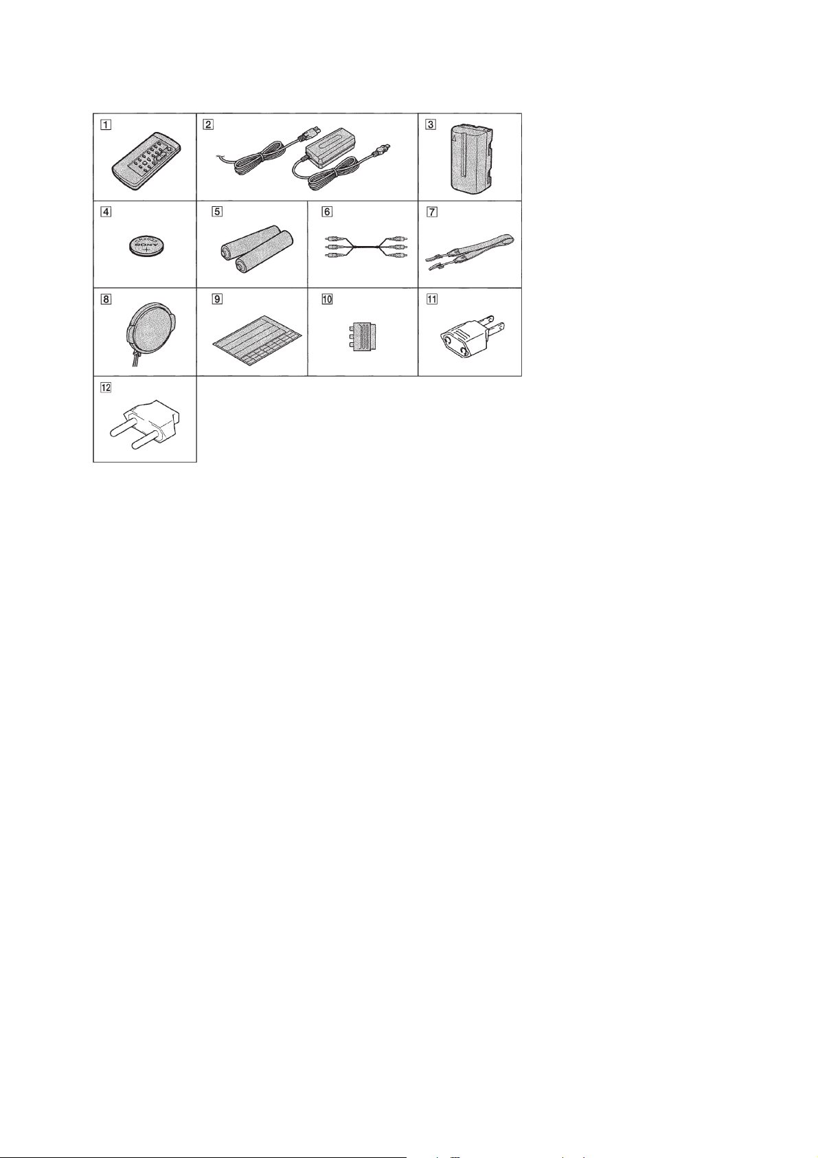
Supplied accessories
1 Wireless Remote Commander (1)
2 AC-L10A/L10B/L10C AC power
adaptor (1), Power cord (1)
3 NP-F330 Battery pack (1)
4 CR2025 Lithium Battery (1)
The lithium battery is already installed in your
camcorder.
5 Size AA (R6) battery for Remote
Commander (2)
6 A/V connecting cable (1)
SAFETY-RELATED COMPONENT WARNING!!
COMPONENTS IDENTIFIED BY MARK ! OR DOTTED LINE WITH
MARK ! ON THE SCHEMATIC DIAGRAMS AND IN THE PARTS
LIST ARE CRITICAL TO SAFE OPERATION. REPLACE THESE
COMPONENTS WITH SONY PARTS WHOSE PART NUMBERS
APPEAR AS SHOWN IN THIS MANUAL OR IN SUPPLEMENTS
PUBLISHED BY SONY .
7 Shoulder strap (1)
8 Lens cap (1)
9 Label sheet for cassette (1)
Stick this label on the recorded cassette.
0 21-pin adaptor (1)
DCR-TR7000E/TR7100E/TR V210E: AEP, UK/
TRV310E: AEP, UK/TRV110E: AEP, UK,
EE, NE, RU only
!¡ 2-pin conversion adaptor (1)
DCR-TRV110E: E, HK/TR V110: E, HK, BR/
TRV110P/TRV310E: E, HK/TRV310: E, HK/
TRV310P only
SAFETY CHECK-OUT
After correcting the original service problem, perform the following
safety checks before releasing the set to the customer.
!™ 2-pin conversion adaptor (1)
DCR-TRV110E: JE/TRV310E: JE/
TRV310: JE only
• Abbreviation
EE :
East European model
NE :
North European model
RU : Russian model
HK : Hong Kong model
BR : Brazilian model
JE : Tourist model
ATTENTION AU COMPOSANT AYANT RAPPORT
LES COMPOSANTS IDENTIFÉS P AR UNE MARQUE ! SUR LES
DIAGRAMMES SCHÉMA TIQUES ET LA LISTE DES PIÈCES SONT
CRITIQUES POUR LA SÉCURITÉ DE FONCTIONNEMENT. NE
REMPLACER CES COMPOSANTS QUE PAR DES PIÈSES SONY
DONT LES NUMÉROS SONT DONNÉS DANS CE MANUEL OU
DANS LES SUPPÉMENTS PUBLIÉS PAR SONY.
À LA SÉCURITÉ!
1. Check the area of your repair for unsoldered or poorly-soldered
connections. Check the entire board surface for solder splashes
and bridges.
2. Check the interboard wiring to ensure that no wires are
"pinched" or contact high-wattage resistors.
3. Look for unauthorized replacement parts, particularly
transistors, that were installed during a previous repair. Point
them out to the customer and recommend their replacement.
— 3 —
4. Look for parts which, through functioning, show obvious signs
of deterioration. Point them out to the customer and
recommend their replacement.
5. Check the B+ voltage to see it is at the values specified.
6. Flexible Circuit Board Repairing
• Keep the temperature of the soldering iron around 270˚C
during repairing.
• Do not touch the soldering iron on the same conductor of the
circuit board (within 3 times).
• Be careful not to apply force on the conductor when soldering
or unsoldering.
Page 4

Remark
DCR-
TR7000E/
DCR-
TR7000
DCR-
TRV315
DCR-
TRV310E
TR7100E
AEP, UK
US, CND
US, CND
E, HK, A US,
AEP, UK
NTSC : X251 is 28.6363MHz
PAL : X251 is 28.375MHz
PAL
RMT-814
20×
80×
NTSC
RMT-814
20×
360×
NTSC
RMT-814
20×
360×
CN, JE
PAL
RMT-814
20×
360×
PAL
RMT-814
20×
80×
960H:with IC503 of VC-213 board
®:with Q641-644 of VC-213 board
✕
960H
✕
720H
®
720H
®
960H
®
960H
®:with REC button and Q641-
644 of VC-213 board
2.5 inch : with PD-105 board
3/3.5 inch : with PD-106 board
✕
✕
✕
®
✕
✕
®
3.0
89k
®
3.5
105k
✕
3.5
105k
Color : with VF-126 board
✕
✕
TYPE S
TYPE S
TYPE S
B/W : with VF-129 board
Color
Color
Color
B/W
B/W
CD-213
CF-65
CD-212
CF-65
CD-212
CF-63
CD-213
CF-63
CD-213
CF-63
MA-357✕VF-126
MA-357✕VF-126
MA-355
MA-355
MA-355
PD-106
VF-126
PD-106
VF-129
PD-106
VF-129
SE-89
SE-89
SE-87
SE-87
SE-87
PJ-98
PJ-98
PJ-96
PJ-96
PJ-96
DCR-
TRV310/
DCR-
TRV210E
DCR-
TRV210
DCR-
TRV203
DCR-
TRV110E
TRV310P
US, E, HK,
JE, TW
NTSC
CN
PAL
AEP, UK
PAL
US, CND
NTSC
CND
NTSC
E, HK, A US,
CN, JE
PAL
AEP, UK,
EE, NE, RU
PAL
RMT -814
RMT-814
RMT-814
RMT-814
RMT-814
RMT-814
RMT -814
20×
20×
20×
20×
20×
20×
20×
360×
720H
360×
960H
80×
960H
360×
720H
360×
720H
360×
960H
80× (Note)
960H
®
®
3.5
105k
TYPE C
B/W
CD-212
CF-63
MA-355
PD-106
VF-129
SE-87
PJ-96
®
®
3.0
89k
TYPE S
B/W
CD-213
CF-63
MA-355
PD-106
VF-129
SE-87
PJ-96
®
✕
3.0
89k
TYPE S
B/W
CD-213
CF-63
MA-355
PD-106
VF-129
SE-87
PJ-96
®
®
3.0
89k
TYPE S
B/W
CD-212
CF-63
MA-355
PD-106
VF-129
SE-87
PJ-96
®
®
3.0
89k
TYPE S
B/W
CD-212
CF-63
MA-355
PD-106
VF-129
SE-87
PJ-96
®
®
2.5
61k
TYPE S
B/W
CD-213
CF-62
MA-354
PD-105
VF-129
SE-86
PJ-95
®
✕
2.5
84k
TYPE S
B/W
CD-213
CF-62
MA-354
PD-105
VF-129
SE-86
PJ-95
DCR-
TRV110/
TRV110P/
TRV103
US, CND,
E, HK, BR
Model
Table for difference of function
Destination
NTSC
RMT-814
20×
Color system
Remote Commander
Lens
®
360×
720H
Digital zoom
CCD imager
MONITOR IN
®
VTR REC
2.5
61k
LCD (size)
LCD (pixel)
— 4 —
TYPE S
B/W
LCD type
View finder
CD-212
CF-62
CD board
CF board
MA-354
PD-105
MA board
PD board
VF-129
SE-86
VF board
SE board
PJ-95
PJ board
Note : EE, NE, RU model is 360×.
CND : Canadian model
EE : East European model
NE : North European model
• Abbreviation
RU : Russian model
HK : Hong Kong model
AUS : Australian model
CN : Chinese model
BR : Brazilian model
JE : Tourist model
TW : Taiwan model
Page 5

TABLE OF CONTENTS
SERVICE NOTE
1. POWER SUPPLY DURING REPAIRS ····························· 8
2. TO TAKE OUT A CASSETTE WHEN NOT EJECT
(FORCE EJECT) ································································ 8
SELF-DIAGNOSIS FUNCTION
1. Self-diagnosis Function ······················································ 9
2. Self-diagnosis Display························································ 9
3. Service Mode Display ························································9
3-1. Display Method ··································································9
3-2. Switching of Backup No. ··················································· 9
3-3. End of Display···································································· 9
4. Self-dignosis Code Table·················································· 10
1. GENERAL
Quick Start Guide ······································································1-1
Getting Started··········································································· 1-1
Using this manual ··································································1-1
Checking supplied accessories ··············································1-1
Step 1: Preparing the power supply·······································1-2
Step 2: Inserting a cassette ····················································1-3
Recording – Basics ····································································1-3
Recording a picture································································ 1-3
Checking the recording
– END SEARCH/EDITSEARCH/Rec Review····················· 1-5
Playback – Basics ······································································1-5
Playing back a tape ································································1-5
Viewing the recording on TV ················································1-6
Advanced Recording Operations···············································1-6
Photo recording······································································1-6
Using the wide mode ·····························································1-7
Using the fader function ························································1-7
Using special effects – Picture effect·····································1-8
Using special effects – Digital effect····································· 1-8
Using the PROGRAM AE function ·······································1-9
Adjusting the exposure manually ··········································1-9
Focusing manually······························································· 1-10
Inserting a scene ··································································1-10
Advanced Playback Operations···············································1-10
Playing back a tape with picture effects ······························1-10
Playing back a tape with digital effects ·······························1-10
Quickly locating a scene using the zero set memory
function ················································································1-11
Searching a recording by date··············································1-11
Searching for a photo – Photo search/Photo scan················1-11
Editing on Other Equipment····················································1-12
Dubbing a tape ·····································································1-12
Recording video or TV programs ········································1-12
Inserting a scene from a VCR··············································1-13
Customizing Y our Camcorder ·················································1-13
Changing the MENU settings ··············································1-13
Resetting the date and time·················································· 1-14
Additional Information ····························································1-14
Digital8 system, recording and playback·····························1-15
Changing the lithium battery in your camcorder ·················1-15
Troubleshooting ···································································1-16
Self-diagnosis display ··························································1-17
Warning indicators and messages ········································1-17
Using your camcorder abroad··············································1-17
Maintenance information and precautions···························1-17
Quick Reference ······································································1-18
Identifying the parts and controls ········································1-18
Quick Function Guide ·························································1-20
2. DISASSEMBLY
2-1. 2.5 INCH LCD Unit, PD-105 Board ·······························2-2
2-2. 3.0/3.5 INCH LCD Unit, PD-106 Board························· 2-3
2-3. F Panel Assembly, Cabinet (R) Assembly ·······················2-4
2-4. MA-354, 355, 357 Board ················································2-4
2-5. Mechanism Deck ·····························································2-5
2-6. EVF Block Assembly ······················································2-6
2-7. VF-129 Board (B/W EVF Model)···································2-7
2-8. VF-126 Board (Color EVF Model) ·································2-8
2-9. Lens Block·······································································2-9
2-10. Mechanism Deck, VC-213, DD-117,
PJ-95, 96, 98 Boards······················································2-10
2-11. CF-65 Board (TR Model) ··············································2-12
2-12. CF-62 Board (2.5 INCH LCD Model) ··························2-12
2-13. CF-63 Board (3.0/3.5 INCH LCD Model) ····················2-12
2-14. Circuit Boards Location ················································2-13
2-15. Flexible Boards Location ··············································2-14
3. BLOCK DIAGRAMS
3-1. Overall Block Diagram (1) ··············································3-1
Overall Block Diagram (2)··············································3-6
3-2. Power Block Diagram (1)················································3-9
Power Block Diagram (2)··············································3-13
4. PRINTED WIRING BOARDS AND
SCHEMATIC DIAGRAMS
4-1. Frame Schematic Diagram-1···········································4-1
Frame Schematic Diagram-2··········································· 4-5
4-2. Printed Wiring Boards and Schematic Diagrams ············4-9
• CD-212 (CCD Imager)
Printed Wiring Board and
Schematic Diagram ·······································4-10
• CD-213 (CCD Imager)
Printed Wiring Board and
Schematic Diagram ·······································4-13
• VC-213 (Camera Processor)(1/13)
Schematic Diagram .......................................4-15
• VC-213 (Y/C Processor)(2/13)
Schematic Diagram ·······································4-18
• VC-213 (Lens Motor Drive)(3/13)
Schematic Diagram ·······································4-21
• VC-213 (I/O SEL, IR, BBI)(4/13)
Schematic Diagram ·······································4-25
• VC-213 (VFD)(5/13)
Schematic Diagram ·······································4-29
• VC-213 (SFD, TFD, LIP)(6/13)
Schematic Diagram ·······································4-33
• VC-213 (TRX, TRF , TRW)(7/13)
Schematic Diagram ·······································4-35
• VC-213 (8mm PB RF AMP, D/A Converter)(8/13)
Schematic Diagram ·······································4-40
• VC-213 (8mm AFM Processor)(9/13)
Schematic Diagram ·······································4-43
• VC-213 (8mm Mechanism Control)(10/13)
Schematic Diagram ·······································4-49
• VC-213 (DV Mechanism Control)(11/13)
Schematic Diagram ·······································4-51
• FP-249 (S/T Reel Sensor), FP-356 (Top Sensor),
FP-355 (Tape LED) Flexible Board ····························4-55
• VC-213 (Servo)(12/13)
Schematic Diagram ·······································4-56
• VC-213 (HI Control)(13/13)
Schematic Diagram ·······································4-59
• VC-213 (Camera Processor, Y/C Processor, Lens Motor
Drive, IN/OUT Select, IR Transmitter, Base Band Input,
VFD, SFD, TFD, LIP, TRX, TRF, TRW, 8mm PB RF
AMP, D/A Converter, 8mm AFM Processor, 8mm
Mechanism Control, DV Mechanism Control, Servo,
HI Control)
Printed Wiring Board ····································4-65
— 5 —
Page 6

• SE-86/87/89 (Steady Shot), PJ-95/96/98 (AV IN/OUT)
Printed Wiring Boards···································4-70
• SE-86/87/89 (Steady Shot), PJ-95/96/98 (AV IN/OUT)
Schematic Diagrams ·····································4-73
• MA-354/355/357 (Stereo MIC AMP)
Printed Wiring Board ····································4-75
• MA-354/355/357 (Stereo MIC AMP)
Schematic Diagram ·······································4-77
• CF-62 (User Control)
Printed Wiring Board ....................................4-80
• CF-62 (User Control)
Schematic Diagram ·······································4-83
• CF-63 (User Control)
Printed Wiring Board ....................................4-87
• CF-63 (User Control)
Schematic Diagram ·······································4-91
• CF-65 (User Control)
Printed Wiring Board ....................................4-96
• CF-65 (User Control)
Schematic Diagram ·······································4-99
• PD-105 (RGB Decoder, LCD, Timing Generator,
Back Light Drive)
Printed Wiring Board
(2.5 INCH LCD Model)······························ 4-103
• PD-106 (RGB Decoder, LCD, Timing Generator,
Back Light Drive)
Printed Wiring Board
(3.0/3.5 INCH LCD Model)························4-105
• PD-105 (RGB Decoder, LCD)(1/2)
Schematic Diagram ·····································4-109
• PD-106 (RGB Decoder, LCD)(1/2)
Schematic Diagram ·····································4-111
• PD-105, 106 (RGB Decoder, LCD)(2/2)
Schematic Diagram ·····································4-114
• VF-129 (B/W EVF)
Printed Wiring Board (B/W EVF Model) ...4-117
• VF-129 (B/W EVF)
Schematic Diagram (B/W EVF Model)······ 4-118
• VF-126 (Color EVF)
Printed Wiring Board (Color EVF Model) ..4-121
• VF-126 (Color EVF)
Schematic Diagram (Color EVF Model) ····4-123
• DD-117 (DC/DC Converter)
Printed Wiring Board ··································4-129
• DD-117 (DC/DC Converter)
Schematic Diagram ·····································4-131
• FK-8500, SS-8500 (Control Switch Block)
Schematic Diagram ·····································4-138
5. ADJUSTMENTS
1. Before starting adjustment···············································5-1
1-1. Adjusting items when replacing main parts and boards·· 5-2
5-1. CAMERA SECTION ADJUSTMENT··························· 5-4
1-1. Preparations before Adjustment (Camera Section) ·········5-4
1-1-1.List of Service Tools························································5-4
1-1-2.Preparations ····································································· 5-5
1-1-3.Precaution ········································································5-9
1. Setting the Switch····························································5-9
2. Order of Adjustments ······················································5-9
3. Subjects ···········································································5-9
1-2. Initialization of C, D, E, F Page Data····························5-10
1-2-1.Initialization of C Page Data ·········································5-10
1. Initializing the C Page Data···········································5-10
2. Modification of C Page Data········································· 5-10
3. C Page Table ··································································5-10
1-2-2.Initialization of D Page Data ········································· 5-12
1. Initializing the D Page Data ··········································5-12
2. Modification of D Page Data·········································5-12
3. D Page Table··································································5-12
1-2-3.Initialization of E, F Page Data ·····································5-14
1. Initializing the E, F Page Data·······································5-14
2. Modification of E, F Page Data·····································5-14
3. F Page Table ··································································5-14
4. E Page Table ··································································5-18
1-3. Camera System Adjustments·········································5-21
1. HALL Adjustment ·························································5-21
2. Flange Back Adjustment (Using Minipattern Box)·······5-22
3. Flange Back Adjustment (Using Flange Back Adjustment
Chart Subject More Than 500m Away)·························5-23
3-1. Flange Back Adjustment (1) ··········································5-23
3-2. Flange Back Adjustment (2) ··········································5-23
4. Flange Back Check························································5-24
5. Picture Frame Setting ····················································5-24
6. AGC Gain Calibration Adjustment ·······························5-25
7. Color Reproduction Adjustment····································5-26
8. IRIS IN/OUT Adjustment ·············································5-27
9. Auto White Balance Standard Data Input ·····················5-28
10. Auto White Balance Adjustment ···································5-28
11. White Balance Check ····················································5-29
12. Angular Velocity Sensor Sensitivity Data Check ··········5-30
1-4. Color Electronic Viewfinder System Adjustments
(DCR-TR7000/TR7000E/TR7100E/TRV315)··············5-31
1. EVF Initial Data Input ···················································5-31
2. VCO Adjustment (VF-126 board)·································5-32
3. Bright Adjustment (VF-126 board) ·······························5-32
4. Contrast Adjustment (VF-126 board)····························5-33
5. Backlight Consumption Current Adjustment
(VF-126 board)······························································5-33
6. White Balance Adjustment (VF-126 board)··················5-34
1-5. Monochrome Electronic Viewfinder System Adjustments
(DCR-TRV103/TRV110/TRV110E/TRV110P/TRV203/
TRV210/TRV210E/TRV310/TRV310E/TRV310P)······5-35
1-5-1.Horizontal Slant Check ·················································5-35
1-5-2.Centering Adjustment····················································5-35
1-5-3.Focus Adjustment ··························································5-35
1-5-4.Aberration Adjustment ··················································5-36
1-5-5.Horizontal Amplitude Adjustment (VF-129 board) ······5-36
1-5-6.Vertical Amplitude Adjustment (VF-129 board) ··········· 5-37
1-5-7.Brightness Adjustment (VF-129 Board)························ 5-37
1-5-8.Horizontal Amplitude, V ertical Amplitude,
Focus Check ··································································5-37
1-6. LCD System Adjustments
(DCR-TRV103/TRV110/TRV110E/TRV110P/TRV203/
TRV210/TRV210E/TRV310/TRV310E/TRV310P/
TRV315) ········································································5-38
1. LCD Initial Data Input (1)·············································5-38
2. LCD Initial Data Input (2)·············································5-38
3. VCO Adjustment (PD-105/106 board)··························5-39
4. D range Adjustment (PD-105/106 board) ·····················5-39
5. Bright Adjustment (PD-105/106 board)························5-40
6. Contrast Adjustment (PD-105/106 board)·····················5-40
7. V-COM Level Adjustment (PD-105/106 board) ···········5-41
8. Color Adjustment (PD-105/106 board) ·························5-41
9. V-COM Adjustment (PD-105/106 board) ·····················5-42
10. White Balance Adjustment (PD-105/106 board)···········5-42
5-2. MECHANISM SECTION ADJUSTMENT··················5-43
2-1. Hi8/Standard 8mm Mode ··············································5-43
2-1-1.Operating Without Cassette ···········································5-43
2-1-2.Tape Path Adjustment····················································5-43
1. Preparations for Adjustment··········································5-43
2-2. Digital8 Mode································································5-44
2-2-1.How to Enter Record Mode Without Cassette ··············5-44
2-2-2.How to Enter Playback Mode Without Cassette ···········5-44
2-2-3.Overall Tape Path Check ···············································5-44
— 6 —
Page 7

1. Recording of the tape path check signal························5-44
2. Tape path check ·····························································5-44
5-3. VIDEO SECTION ADJUSTMENT······························5-45
3-1. Preparations Before Adjustments ··································5-45
3-1-1.Equipment to Required·················································· 5-45
3-1-2.Precautions on Adjusting···············································5-46
3-1-3.Adjusting Connectors ···················································· 5-47
3-1-4.Connecting the Equipment ············································5-47
3-1-5.Alignment Tape ·····························································5-48
3-1-6.Input/Output Level and Impedance ·······························5-49
3-2. System Control System Adjustment······························5-50
1. Initialization of C, D, E, F Page Data····························5-50
2. Battery End Adjustment (VC-213 board)······················5-50
3-3. Servo and RF System Adjustments ·······························5-51
1. PLL f0 & LPF f0 Pre-adjustment (VC-213 board) ········· 5-51
2. Switching Position Adjustment (VC-213 board)··········· 5-51
3. AGC Center Level Adjustment (VC-213 board) ···········5-52
4. APC & AEQ Adjustment (VC-213 board) ···················· 5-52
5. PLL f0 & LPF f0 Final Adjustment (VC-213 board)······5-53
6. Hi8/standard 8mm Switching Position Adjustment
(VC-214 board) ·····························································5-53
7. CAP FG Offset Adjustment (VC-213 board) ················5-54
3-4. Video System Adjustments ············································5-55
3-4-1.Video System Adjustments············································ 5-55
1. 27 MHz/36 MHz Origin Oscillation Adjustment
(VC-213 board) ·····························································5-55
2. Chroma BPF f0 Adjustment (VC-213 board) ················5-55
3. S VIDEO OUT Y Level Adjustment (VC-213 board)···5-56
4. S VIDEO OUT Chroma Level Adjustment
(VC-213 board) ·····························································5-56
5. VIDEO OUT Y, Chroma Level Adjustment
(VC-213 board) ·····························································5-57
6. Hi8/standard 8mm 14 MHz Origin Oscillation
Adjustment (VC-213 board)········································· 5-57
7. BBI PLL Adjustment (VC-213 board) ··························5-58
8. Hi8/standard 8mm Y OUT Level Adjustment
(VC-213 board) ·····························································5-58
9. Hi8/standard 8mm Chroma Level Adjustment
(VC-213 board) ·····························································5-59
10. Hi8/standard 8mm AFC f
(VC-213 board) ·····························································5-59
11. Hi8/standard 8mm RP Filter f0 Adjustment
(VC-213 board) ·····························································5-60
3-4-2.BIST Check ···································································5-61
1. Playback System Check ················································5-61
1-1. Preparation for Playback ···············································5-61
1-2. IC104 (TRX) BIST (PB) Check ····································5-61
1-3. IC302 (TFD) BIST (PB) Check ····································5-61
1-4. IC301 (SFD) BIST (PB) Check·····································5-61
1-5. IC351 (VFD) BIST (PB) Check ····································5-62
2. Recording System Check ··············································5-64
2-1. Preparations for Recording············································5-64
2-2. IC351 (VFD) BIST (REC) Check ································· 5-64
2-3. IC301 (SFD) BIST (REC) Check··································5-64
2-4. IC302 (TFD) BIST (REC) Check ·································5-64
2-5. IC104 (TRX) BIST (REC) Check ································· 5-65
3-5. IR Transmitter Adjustments···········································5-66
1. IR Video Carrier Frequency Adjustment
(VC-213 board) ·····························································5-66
2. IR Video Deviation Adjustment (VC-213 board) ·········· 5-66
3. IR Audio Deviation Adjustment (VC-213 board) ·········5-67
3-6. Audio System Adjustment·············································5-68
1. Hi8/standard 8mm AFM BPF f0 Adjustment
(VC-213 board) ·····························································5-68
2. Hi8/standard 8mm AFM 1.5 MHz Deviation Adjustment
(VC-213 board) ·····························································5-69
3. Hi8/standard 8mm AFM 1.7 MHz Deviation Adjustment
(VC-213 board) ·····························································5-69
Adjustment
0
4. Digital8 Playback Level Check ·····································5-69
5. Overall Level Characteristics Check ·····························5-69
6. Overall Distortion Check···············································5-69
7. Overall Noise level Check············································· 5-70
8. Overall Separation Check·············································· 5-70
5-4. SERVICE MODE ··························································5-71
4-1. Adjustment Remote Commander ··································5-71
1. Using the Adjustment Remote Commander··················5-71
2. Precautions Upon Using the Adjustment Remote
Commander ···································································5-71
4-2. Data Process ··································································5-72
4-3. Service Mode·································································5-73
1. Setting the Test Mode ···················································· 5-73
2. Emergence Memory Address ········································5-73
2-1. C Page, Emergence Memory Address ···························5-73
2-2. F Page, Emergence Memory Address ···························5-74
2-3. EMG Code (Emergency Code) ·····································5-74
2-4. MSW Code ····································································5-75
3. Bit V alue Discrimination ···············································5-76
4. Input/Output Check ·······················································5-76
5. LED, LCD (Display Window) Check ···························5-76
6. Record of Use Check····················································· 5-77
7. Switch Check (1) ··························································· 5-77
8. Switch Check (2) ··························································· 5-78
9. Audio (L) Jack Check····················································5-78
10. Headphone Jack Check ·················································5-78
6. REPAIR PARTS LIST
6-1. Exploded Vie ws ·······························································6-1
6-1-1.Front Panel (N) and Battery Panel (P) Block Assembly ·6-1
6-1-2.Cabinet (R) Block Assembly (TR Model)·······················6-2
6-1-3.Cabinet (R) Block Assembly (2.5 INCH LCD Model) ···6-3
6-1-4.Cabinet (R) Block Assembly
(3.0/3.5 INCH LCD Model) ············································6-4
6-1-5.Cabinet (L) Block and Main Boards Assembly··············· 6-5
6-1-6.LCD Block Assembly (2.5 INCH LCD Model) ··············6-6
6-1-7.LCD Block Assembly (3.0/3.5 INCH LCD Model) ········6-7
6-1-8.B/W EVF Block Assembly·············································· 6-8
6-1-9.Color EVF Block Assembly············································6-9
6-1-10. Lens Block Assembly ················································· 6-10
6-1-11. Cassette Compartment Assembly ·······························6-11
6-1-12. LS Chassis Assembly··················································6-12
6-1-13. Mechanism Chassis Assembly····································6-13
6-2. Electrical Parts List ·······················································6-14
* The color reproduction frame is shown on page 323.
— 7 —
Page 8
SERVICE NOTE
1. POWER SUPPLY DURING REPAIRS
In this unit, about 10 seconds after power is supplied (8.4V) to the
battery terminal using the service power cord (J-6082-223-A), the
power is shut off so that the unit cannot operate.
This following two methods are av ailable to pre vent this. Take note
of which to use during repairs.
Method 1.
Connect the servicing remote commander RM-95 (J-6082-053-B)
to the LANC jack, and set the remote commander switch to the
“ADJ” side.
Method 2.
Press the battery switch of the battery terminal using adhesive tape,
etc.
Method 3.
Battery terminal
‘
Use the DC IN terminal. (Use the AC power adaptor.)
DC IN terminal
Battery SIG terminal
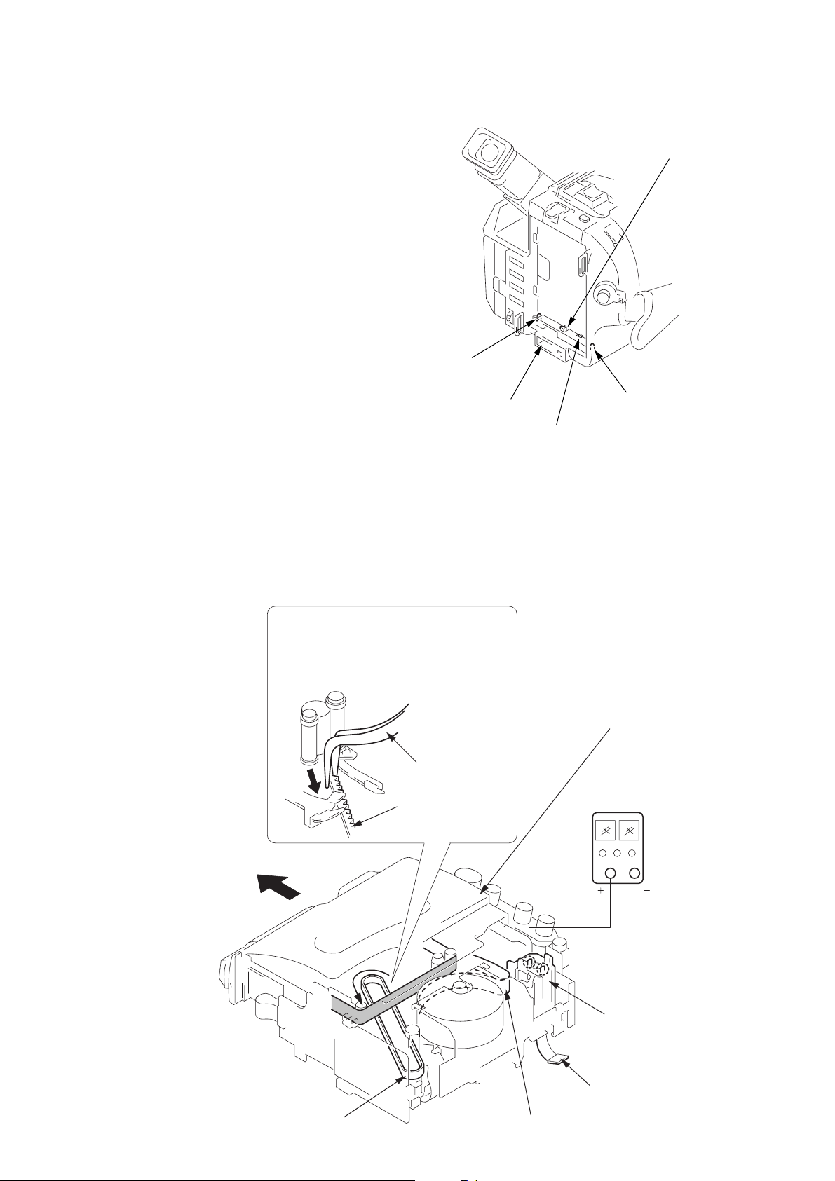
2. TO TAKE OUT A CASSETTE WHEN NOT EJECT (FORCE EJECT)
1 Refer to 2-1. to remove the front panel assembly.
2 Refer to 2-1. to remove the cabinet (R) assembly.
3 Refer to 2-1. to remove the battery panel assembly.
4 Refer to 2-1. to remove the cabinet (L) assembly.
5 Disconnect CN901 of VC-213 board.
6 Add +5V from the DC POWER SUPPLY and unload with a
pressing the cassette lid.
Battery switch
Battery terminal
’
7
Let go your hold the cassette
lid and rise the cassette
compartment to take out a cassette.
6
Pull the timing belt in the direction of
A
arrow
the cassette lid (take care not to damage)
to adjust the bending of a tape.
with a pincette while pressing
Pincette
Timing belt
Press the cassette lid to rise
the cassette compartment
[DC power supply]
(+5V)
Loading motor
Timing belt
Disconnect CN901
of VC-213 board.
Adjust the bending of a tape
— 8 —
Page 9
SELF-DIAGNOSIS FUNCTION
1. Self-diagnosis Function
When problems occur while the unit is operating, the self-diagnosis
function starts working, and displays on the viewfinder or Display
window what to do. This function consists of two display; selfdiagnosis display and service mode display.
Details of the self-diagnosis functions are provided in the Instruction
manual.
Viewfinder Display window
C : 3 1 : 1 1
Repaired by:
C : Corrected by customer
H : Corrected by dealer
E : Corrected by service
engineer
Blinks at 3.2Hz
C
Indicates the appropriate
step to be taken.
E.g.
31 ....Reload the tape.
32 ....Turn on power again.
3 1
Block
1 1
C : 3 1 : 11
Refer to page 10 and 11.
Self-diagnosis Code Table.
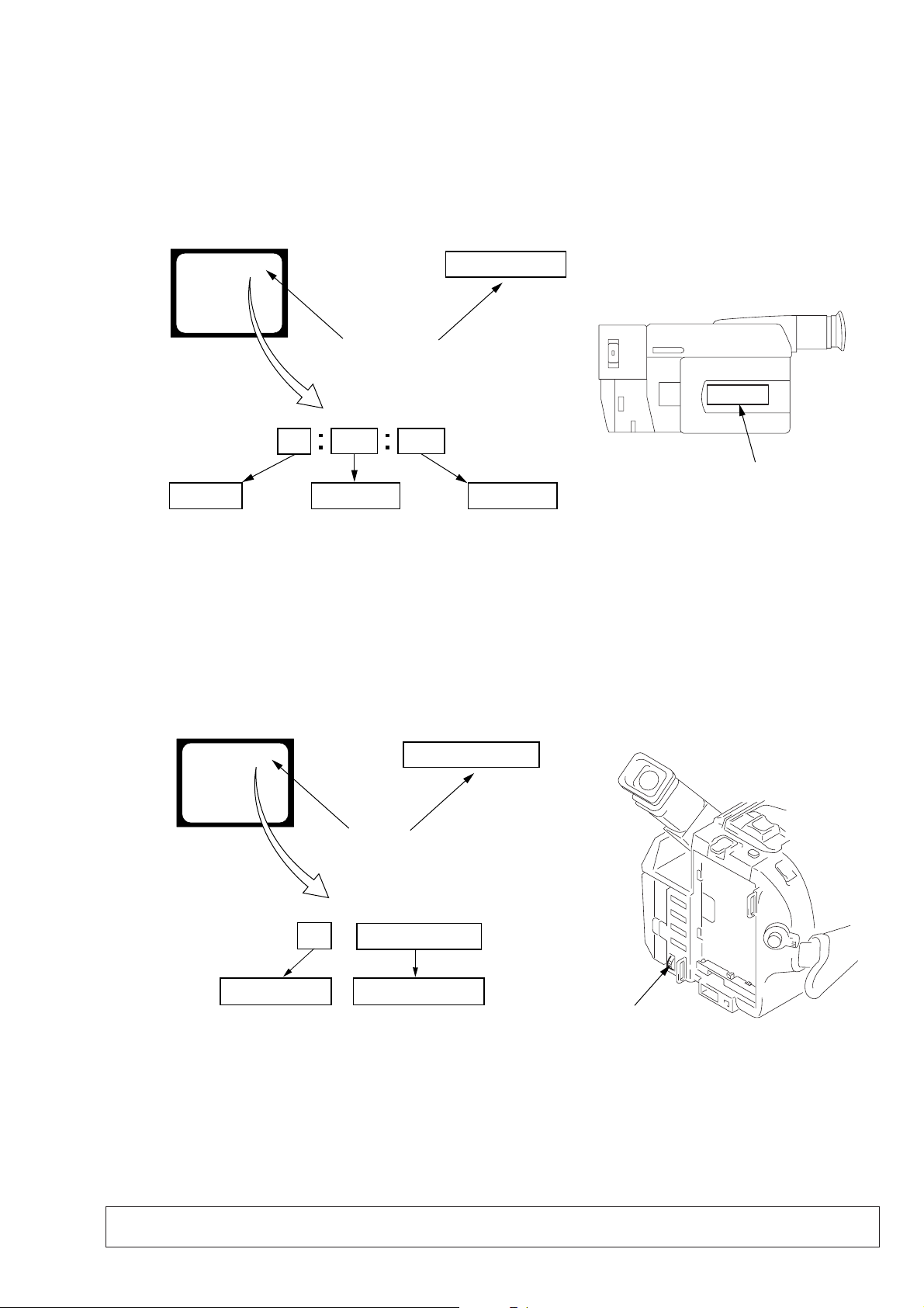
2. Self-diagnosis Display
When problems occur while the unit is operating, the counter of the
viewfinder or Display window shows a 4-digit display consisting
of an alphabet and numbers, which blinks at 3.2 Hz. This 5-character
display indicates the “repaired by:”, “block” in which the problem
occurred, and “detailed code” of the problem.
Display window
Detailed Code
3. Service Mode Display
The service mode display shows up to six self-diagnosis codes shown in the past.
3-1. Display Method
While pressing the “STOP” key, set the switch from OFF to “VTR or PLAYER”, and continue pressing the “STOP” key for 5 seconds
continuously. The service mode will be displayed, and the counter will show the backup No. and the 5-character self-diagnosis codes.
Viewfinder
[3] C : 3 1 : 1 1
Lights up
[3]
Backup No.
Order of previous errors
C : 3 1 : 1 1
Self-diagnosis Codes
3-2. Switching of Backup No.
By rotating the control dial, past self-diagnosis codes will be shown in order. The backup No. in the [] indicates the order in which the
problem occurred. (If the number of problems which occurred is less than 6, only the number of problems which occurred will be shown.)
[1] : Occurred first time [4] : Occurred fourth time
[2] : Occurred second time [5] : Occurred fifth time
[3] : Occurred third time [6] : Occurred the last time
Display window
3 C : 3 1 : 11
Control dial
3-3. End of Display
Turning OFF the power supply will end the service mode display.
Note: The “self-diagnosis display” data will be back ed up by the coin-type lithium battery (CF-62/63/65 board BH001). When
this coin-type lithium battery is disconnected, the “self-diagnosis display” data will be lost by initialization.
— 9 —
Page 10

4. Self-diagnosis Code Table
Self-diagnosis Code
Block
Function
Repaired by:
C
21
C
22
C
23
C
31
C
31
C
31
C
31
C
31
C
31
C
31
C
31
C
31
C
31
C
31
C
31
C
31
C
32
C
32
C
32
C
32
C
32
C
32
C
32
C
32
C
32
C
32
C
32
C
32
C
32
Detailed
Code
00
00
00
10
11
20
21
22
23
30
31
40
41
42
43
44
10
11
20
21
22
23
30
31
40
41
42
43
44
Symptom/State
Condensation.
Video head is dirty.
Non-standard battery is used.
LOAD direction. Loading does not
complete within specified time
UNLOAD direction. Loading does not
complete within specified time
T reel side tape slacking when unloading
S reel
side tape slacking when unloading
T reel fault.
S reel fault.
FG fault when starting capstan.
FG fault during normal capstan operations.
FG fault when starting drum.
PG fault when starting drum.
FG fault during normal drum operations.
PG fault during normal drum operations.
Phase fault during normal drum operations.
LOAD direction loading motor time-
out.
UNLOAD direction loading motor
time-out.
T reel side tape slacking when
unloading.
S reel side tape slacking when
unloading.
T reel fault.
S reel fault.
FG fault when starting capstan.
FG fault during normal capstan
operations.
FG fault when starting drum.
PG fault when starting drum.
FG fault during normal drum
operations.
PG fault during normal drum
operations.
Phase fault during normal drum
operations.
Correction
Remove the cassette, and insert it again after one hour.
Clean with the optional cleaning cassette.
Use the InfoLITHIUM battery.
Load the tape again, and perform operations from the beginning.
Load the tape again, and perform operations from the beginning.
.
Load the tape again, and perform operations from the beginning.
.
Load the tape again, and perform operations from the beginning.
Load the tape again, and perform operations from the beginning.
Load the tape again, and perform operations from the beginning.
Load the tape again, and perform operations from the beginning.
Load the tape again, and perform operations from the beginning.
Load the tape again, and perform operations from the beginning.
Load the tape again, and perform operations from the beginning.
Load the tape again, and perform operations from the beginning.
Load the tape again, and perform operations from the beginning.
Load the tape again, and perform operations from the beginning.
Remove the battery or power cable, connect, and perform
operations from the beginning.
Remove the battery or power cable, connect, and perform
operations from the beginning.
Remove the battery or power cable, connect, and perform
operations from the beginning.
Remove the battery or power cable, connect, and perform
operations from the beginning.
Remove the battery or power cable, connect, and perform
operations from the beginning.
Remove the battery or power cable, connect, and perform
operations from the beginning.
Remove the battery or power cable, connect, and perform
operations from the beginning.
Remove the battery or power cable, connect, and perform
operations from the beginning.
Remove the battery or power cable, connect, and perform
operations from the beginning.
Remove the battery or power cable, connect, and perform
operations from the beginning.
Remove the battery or power cable, connect, and perform
operations from the beginning.
Remove the battery or power cable, connect, and perform
operations from the beginning.
Remove the battery or power cable, connect, and perform
operations from the beginning.
— 10 —
Page 11

Self-diagnosis Code
Block
Function
Repaired by:
E
61
E
61
E
62
E
62
Detailed
Code
00
10
00
01
Symptom/State
Difficult to adjust focus
(Cannot initialize focus.)
Zoom operations fault
(Cannot initialize zoom lens.)
Handshake correction function does not
work well. (With pitch angular velocity
sensor output stopped.)
Handshake correction function does not
work well. (With yaw angular velocity
sensor output stopped.)
Correction
Inspect the lens block focus reset sensor (Pin !™ of CN551 of VC213 board) when focusing is performed when the control dial is
rotated in the focus manual mode and the focus motor drive circuit
(IC551 of VC-213 board) when the focusing is not performed.
Note: Use the remote commander RM-95 only for the model without the
focus dial.
Inspect the lens block zoom reset sensor (Pin !¢ of CN551 of VC213 board) when zooming is performed when the zoom lens is
operated and the zoom motor drive circuit (IC551 of VC-213 board)
when zooming is not performed.
Inspect pitch angular velocity sensor (SE651 of SE-86/87/89
board) peripheral circuits.
Inspect yaw angular velocity sensor (SE652 of SE-86/87/89
board) peripheral circuits.
— 11 —
Page 12

DCR-TRV103/TRV110/TRV110E/TRV110P/TRV203/TRV210/
TRV210E/TRV310/TRV310E/TRV310P/TRV315
DCR-TR7000/TR7000E/TR7100E
SECTION 1
GENERAL
This section is extracted from instruction
manual. (3-865-973-11)
1-1
Page 13
1-2
Page 14
1-3
Page 15
1-4
Page 16
1-5
Page 17
1-6
Page 18
1-7
Page 19
1-8
Page 20
1-9
Page 21

1-10
Page 22
1-11
Page 23
1-12
Page 24
1-13
Page 25
1-14
Page 26

1-15
Page 27
1-16
Page 28

1-17
Page 29
1-18
Page 30
1-19
Page 31

1-20E
Page 32

DCR-TRV103/TRV110/TRV110E/TRV110P/TRV203/TRV210/
SECTION 2
DISASSEMBLY
The following flow chart shows the disassembly procedure.
TRV210E/TRV310/TRV310E/TRV310P/TRV315
DCR-TR7000/TR7000E/TR7100E
2.5 INCH LCD MODEL
3.0/3.5 INCH LCD MODEL
2-3. F PANEL ASSEMBLY,
CABINET (R) ASSEMBLY
2-5. MECHANISM DECK (Note)
Note : Use the parts only which can be removed
easily from outside of the MECHANISM DECK.
TR MODEL
2.5 INCH LCD MODEL
3.0/3.5 INCH LCD MODEL
2-1. 2.5 INCH LCD UNIT, PD-105 board
2-2. 3.0/3.5 INCH LCD UNIT, PD-106 board
2-4. MA-354, 355, 357
board
2-11. CF-65 board
(TR MODEL)
2-12. CF-62 board
(2.5 INCH LCD MODEL)
2-13. CF-63 board
(3.0/3.5 INCH LCD MODEL)
2.5 INCH LCD check
service position
3.0/3.5 INCH LCD check
service position
MA-354, 355, 357 board
check service position
MECHANISM DECK
check service position
2-6. EVF BLOCK ASSEMBLY
DIGITAL VIDEO CAMERA RECORDER
TR MODEL
2.5 INCH LCD MODEL
3.0 INCH LCD MODEL
3.5 INCH LCD MODEL
B/W EVF MODEL
COLOR EVF MODEL
NTSC MODEL
PAL MODEL
B/W EVF MODEL
COLOR EVF MODEL
2-9. LENS BLOCK
: DCR-TR7000/TR7000E/TR7100E
: DCR-TRV103/TRV110/TRV110E/TRV110P
: DCR-TRV203/TRV210/TRV210E/TRV315
: DCR-TRV310/TRV310E/TRV310P
: DCR-TRV103/TRV110/TRV110E/TRV110P
: DCR-TRV203/TRV210/TRV210E
: DCR-TRV310/TRV310E/TRV310P
: DCR-TR7000/TR7000E/TR7100E
: DCR-TRV315
: DCR-TRV103/TRV110/TRV110P/TRV203/TRV210/TRV310/TRV310P/TRV315/TR7000
: DCR-TRV110E/TRV210E/TRV310E/TR7000E/TR7100E
2-7. VF-129 board
(B/W EVF MODEL)
2-8. VF-126 board
(COLOR EVF MODEL)
2-10. MECHANISM DECK,
VC-213, DD-117,
PJ-95, 96, 98 boards
B/W EVF check service position
How to remove the CRT UNIT
COLOR EVF
check service position
LENS BLOCK
check service position
MECHANISM DECK,
VC-213, DD-117, PJ-95, 96, 98
boards check service position
2-1
Page 33

NOTE: F ollo w the disassembly procedure in the numerical order given.
2-1. 2.5 INCH LCD UNIT, PD-105 BOARD
4
Two screws (M2 × 4),
lock ace, p2
3
Rotate it by 90
in the direction
of the arrow.
1
°
Press the button.
2
Open the LCD panel.
!¡
!¶
PD-105 board
!£
Claws
Claws
6
Claws
Indication LCD
block assembly
PD-105
7
P cabinet (C)(952)
assembly
Hinge
assembly
8
Two tapping screws
×
(B2
!™
Screw
(M2
!¢
Panel frame (93)
8)
×
3)
assembly
!∞
Back light
Cold cathode
fluorescent tube
!§
LCD UNIT
9
Claws
[2.5 INCH LCD CHECK SERVICE POSITION]
Indication LCD
block assembly
PD-105 board
PD-105
!º
P cabinet (M)(952)
assembly
AC POWER
ADAPTOR
5
Two tapping screws
×
(B2
Adjustment
remote commander
(RM-95)
LANC
jack
AC IN
5)
Multi CPC jig
(J-6082-311-A)
CN5501
LCD
Back light
Cold cathode
fluorescent tube
Base
(Use box or the like.)
2-2
Page 34

2-2. 3.0/3.5 INCH LCD UNIT, PD-106 BOARD
3
Rotate it by 90
in the direction
of the arrow.
°
4
Screw (M2 × 4),
lock ace, p2
6
Claws
Indication LCD
block assembly
7
P cabinet (C)(955)
assembly
8
Two tapping screws
(B2 × 8)
1
Press the button.
!º
2
Open the LCD panel.
Claws
!™
Claws
!£
T wo screws
(M2 × 3)
!¶
PD-106 board
!∞
Back light
Cold cathode
fluorescent tube
!§
LCD UNIT
PD-106
!¡
P cabinet (M)(955)
Hinge
assembly
9
Two tapping screws
(B2 × 5)
!¢
Panel frame (958)
assembly
5
Two tapping screws
(B2 × 5)
[3.0/3.5 INCH LCD CHECK SERVICE POSITION]
Indication LCD
block assembly
PD-106 board
PD-106
CN5501
Multi CPC jig
(J-6082-311-A)
LCD
Back light
Cold cathode
fluorescent tube
Base
(Use box or the like.)
2-3
Adjustment
remote commander
(RM-95)
AC POWER
ADAPTOR
LANC
jack
AC IN
Page 35

2-3. F PANEL ASSEMBLY, CABINET (R) ASSEMBLY
2
Remove
the claw
!º
8
FP-77 flexible board (22P)
Cushion (N)
VC-213
!£
Screw (M2 × 4),
lock ace, p2
1
Two screws (M2 × 4),
lock ace, p2
4
Screw
(M2
lock ace, p2
3
Cabinet (S) shoe
9
Panel (N) (front)
assembly
Note: the TR models do not have
the harness (DP-74 (2.5 INCH LCD MODEL)
or DP-75 (3.0/3.5 INCH LCD MODEL))
shown by Note.
2-4. MA-354, 355, 357 BOARD
6
Screw (M2 × 4),
lock ace, p2
×
4),
!¢
Two screws (M2 × 4),
lock ace, p2
7
Remove the claws
Remove it while taking
care as the FP-77 flexible
cable is connected.
2
FP-76 flexible board (8P)
Note
1
Two tapping screws (B2 × 5)
3
Two tapping screws
(B2
×
5)
6
Tapping screw
×
(B2
4
Control switch block
5)
(MF-9500) (4P)
5
Two harnesses
(from microphone)
5
Screw
×
(M2
4),
lock ace, p2
!™
Screw (M2 × 4),
lock ace, p2
!∞
Remove the
claws
!¡
Three screws (M2 × 4),
lock ace, p2
!§
Cabinet (R) assembly
7
MA-354, 355, 357 board
[MA-354, 355, 357 BOARD CHECK SERVICE POSITION]
Adjustment remote
commander (RM-95)
LANC jack
FP-77 flexible board (22P)
VC-213
Control switch block
(MF-9500) (4P)
MA-354, 355, 357 board
FP-76 flexible board (8P)
2-4
CPC-13 jig
(J-6082-443-A)
CPC-13 jig
Insulater
side
AC POWER
ADAPTOR
DC IN
AC IN
Note: the TR models do not have the harness
Note
(DP-74 (2.5 INCH LCD MODEL)
or DP-75 (3.0/3.5 INCH LCD MODEL))
shown by Note.
Cabinet (R) assembly
Page 36

2-5. MECHANISM DECK
1
Two screws (M2 ×3),
lock ace, p2
3
Screw (M2 × 4),
lock ace, p2
9
Jack cover
2
Cassette lid assembly
Remove it in the direction
of the arrow
5
Battery panel (P)
assembly
b
b
Remove it in the direction
.
of the arrow
Remove it gently as a thin flexible
board is held by a claw.
6
Disengage the claw
that fixes the flexible board.
a
a
.
a
!º
Cabinet (L)
assembly
!™
MD frame (B)
Note: the TR models do not have the harness
(DP-74 (2.5 INCH LCD MODEL)
or DP-75 (3.0/3.5 INCH LCD MODEL))
shown by Note.
4
Screw (M2 × 4),
lock ace, p2
!¡
Two screws
×
(M2
3)
Note
VC-213
7
Screw
[MECHANISM DECK CHECK SERVICE POSITION]
• How to move up the cassette
compartment manually
Press the cassette compartment
in the direction of the arrow
to move it up in the direction of
the arrow
d
.
c
c
DC IN
8
Screw (M2 × 3)
a
PAL MODELS ONLY
In the PAL models, remove
the MD frame (B) after
completing step
1
!¡
.
VC-213
Screw (M2 × 3)
AC POWER
ADAPTOR
b
2
Remove the shield
plate by sliding it in
the arrow direction.
b
3
MD frame (B)
and IM shield
assembly
AC IN
Cabinet (L) assembly
d
FP-77 flexible board (22P)
Panel (N) (front) assembly
Note
Note
Cabinet (R) assembly
2-5
LANC
jack
Adjustment remote
commander (RM-95)
Battery panel (P) assembly
Base
(Use box or the like.)
Note: the TR models do not have the harness
(DP-74 (2.5 INCH LCD MODEL)
or DP-75 (3.0/3.5 INCH LCD MODEL))
shown by Note.
Page 37

2-6. EVF BLOCK ASSEMBLY
< TR MODEL >
3
Three tapping
screws (B2
< 2.5 INCH LCD MODEL >
6
5
Color EVF block assembly
2
FP-47 flexible board (20P)
4
Remove
the claws
4
×
5)
1
FFC-236 flexible
flat cable (50P)
Three tapping
screws (B2
B/W EVF block assembly
×
5)
3
FFC-256
flexible flat cable (4P)
5
Remove
the claws
1
FFC-236 flexible
flat cable (50P)
2
DP-74 harness
(10P)
< 3.0/3.5 INCH LCD MODEL WITH B/W EVF >
6
B/W EVF block assembly
3
FFC-256
flexible flat cable (4P)
5
Remove
the claws
4
Three tapping
screws (B2
Refer to page 2-7 for disassembly of VF-129 board (B/W EVF).
Refer to page 2-8 for disassembly of VF-126 board (Color EVF).
×
5)
1
FFC-236 flexible
flat cable (50P)
2
DP-75 harness
(10P)
< 3.0 INCH LCD MODEL WITH COLOR EVF >
6
Color EVF block assembly
3
FP-47 flexible board (20P)
5
Remove
the claws
4
Three tapping
screws (B2
×
5)
1
FFC-236 flexible
flat cable (50P)
2
DP-75 harness
(10P)
2-6
Page 38

VC-213
Tilt lock (93)
1
Screw
2
Slide the button in the
direction of the arrow
a
.
a
b
c
AC POWER
ADAPTOR
FP-77 flexible board (22P)
Cabinet (R) assembly
AC IN
LANC jack
DC IN
Adjustment remote
commander (RM-95)
CPC-13 jig
(J-6082-443-A)
CPC-13 jig
@¡
CRT socket (4P)
@¢
CRT
@£
Anode cable (1P)
Do not pull the cable,
but remove it in the vertical
direction.
@™
Remove the connector
cover with a flat head (–)
screwdriver.
@º
CRT DT connector (4P)
[How to remove the CRT unit]
FFC-236 flexible
flat cable (50P)
DP-74 harness (10P) (2.5 INCH LCD MODEL)
DP-75 harness (10P) (3.0/3.5 INCH LCD MODEL)
4
Finder (S) assembly
!™
Two tapping
screws (B2
×
5)
!§
Tapping
screw (B2 × 5)
!¶
EVF tally
!∞
EVF cabinet (upper B) (95)
assembly
!¢
EVF cabinet (lower B) (95)
!¡
Tapping screw (B2 × 5)
8
FFC-256
flexible flat cable (4P)
!£
FFC-256
flexible flat cable (4P)
FFC-256 flexible flat cable (4P)
9
VF base(B)(95)
!º
3
Rotate it in the direction of
the arrow
b
and remove it
in the direction of the arrow c.
7
Remove
the claw
6
Two screws
(M2 × 3)
5
Harness guide
!ª
CRT assembly
CRT assembly
!•
VF-129 board
VF-129 board
[B/W EVF CHECK SERVICE POSITION]
Panel (N) (front) assembly
Note: the TR models do not have the harness
(DP-74 or DP-75)
Insulater
side
2-7. VF-129 BOARD (B/W EVF MODEL)
2-7
Page 39

2-8. VF-126 BOARD (COLOR EVF MODEL)
9
FP-47 flexible board
4
!¡
8
Remove the claw
!º
Slide base (C) (95)
assembly
7
Remove the harness
retainer from FP-47
flexible board
6
Two screws (M2 × 3)
lock ace, p2
2
Screw (M2 × 3)
lock ace, p2
1
Harness guide
Remove the slide fixed base (C)
by sliding it in the arrow direction
Claws
Claws
!¢
(rear C) (95)
5
Slide fixed base (C)
3
VF base (C) (95)
Claws
EVF cabinet
!£
Two tapping
screws (B2
!§
EVF cabinet (upper C) (95)
!∞
Two tapping
screws (B2
×
5)
!•
EVF cabinet
(lower C) (95)
!ª
×
5)
@¢
VF-126 board
@∞
!¶
FP-47 flexible
board
[COLOR EVF CHECK SERVICE POSITION]
LANC jack
FP-77 flexible board (22P)
VC-213
FFC-236 flexible
flat cable (50P)
!™
Turn the lever
in the direction
of the arrow.
Adjustment remote
commander (RM-95)
CPC-13 jig
(J-6082-443-A)
AC POWER
ADAPTOR
Claws
@º
@£
@¡
VF-126 board
CPC-13 jig
Insulater
DC IN
side
AC IN
DP-75 harness (10P)
Note: the TR models do not have
the harness (DP-75)
FP-47 flexible board
@™
Claws
Board holder
Panel (N) (front) assembly
Cabinet (R) assembly
2-8
VF-126 board
VF-126 board
VF lens assembly
Page 40

)
)
2-9. LENS BLOCK
!¡
LENS block
9
Ferrite bead
8
FP-45 flexible board (8P)
7
Screw (M2 × 3)
!º
Flexible board (from LENS block) (24P)
5
Screw (M2 × 3)
6
Screw
(M2
×
3)
VC-213
Board
4
FP-54 flexible board (16P)
1
FFC-236 flexible flat cable (50P)
2
DP-74 harness (10P) (2.5 INCH LCD MODEL)
DP-75 harness (10P) (3.0/3.5 INCH LCD MODEL)
Note
[LENS BLOCK CHECK SERVICE POSITION]
Flexible board
(from LENS block) (24P)
Extension cable
(J-6082-357-A) (16P)
VC-213
LENS block
FP-77 flexible board
(22P)
Board
LANC jack
Adjustment remote
commander (RM-95)
CPC-13 jig
(J-6082-443-A)
AC POWER
ADAPTOR
FFC-236 flexible
flat cable (50P)
3
Cabinet (R) assembly
Note: the TR models do not have
the harness (DP-74 or DP-75
shown by Note.
CPC-13 jig
Insulater
DC IN
side
AC IN
Base
Panel (N) (front) assembly
(Fix the lens block using a vise or the like.)
Cabinet (R) assembly
DP-74 harness (10P) (2.5 INCH LCD MODEL)
DP-75 harness (10P) (3.0/3.5 INCH LCD MODEL)
Note
Note: the TR models do not have
the harness (DP-74 or DP-75
shown by Note.
2-9
Page 41

2-10.MECHANISM DECK, VC-213, DD-117, PJ-95, 96, 98 BOARDS
!™
Remove it in the direction of the arrow
b
1
T wo screws
×
(M2
3),
lock ace, p2
@º
Slide it in the direction
of the arrow
c
and
disengage the claw
Remove the control switch
block(FK-8500) in the
direction of the arrow
@¢
Remove the claws
@¡
T wo screws
(M2
×
4),
lock ace, p2
e
d
.
.
7
2
Cassette
Lid
assembly
Remove
!ª
the claw
e
d
Cabinet (R) assembly
b
.
Jack cover
4
Screw
×
(M2
e
lock ace,
p2
c
4),
!•
board
3
Screw (M2 × 4),
lock ace, p2
!¡
Control switch block
(SS-8500)
8
Screw
DD-117
VC-213
Board
@∞
board
!º
T wo tapping
screws (B2
DD-117
VC-213
!¶
Remove it in the direction
of the arrow
a
.
Remove it gently as a thin
flexible board is held by a claw.
6
Disengage the claw
that fixes the flexible board.
×
5)
a
5
Battery panel
(P) assembly
!§
T wo screws
×
(M2
3)
Board to board connector (70P)
@™
PJ-95, 96, 98 board
@§
Mechanism
deck
PAL MODELS ONLY
!¢
Claw
9
Screw
(M2
!∞
IM shield assembly
!£
Screw
×
(M2
3)
@£
Screw
(M2
×
3)
×
3)
2-10
Page 42

[MECHANISM DECK, VC-213, DD-117, PJ-95, 96, 98 BOARDS CHECK SERVICE POSITION]
Base 1-3 (Use box or the like)
Mechanism deck
SE-86, 87, 89 board
Base 3
FP-77 flexible
board (22P)
Panel (N) (front)
assembly
AC IN
DC IN
DD-117 board
Extension cable
(J-6082-439-A) (70P)
VC-213
PJ-95, 96,
98 board
Battery panel (P)
AC POWER
ADAPTOR
assembly
DD-117
FP-45 flexible board
Base 2
Control switch block (SS-8500)
Adjustment remote
commander (RM-95)
Control switch
block (FK-8500)
Base 1
VC-213 board
FFC-236 flexible
flat cable (50P)
DP-74 harness (10P) (2.5 INCH LCD MODEL)
DP-75 harness (10P) (3.0/3.5 INCH LCD MODEL)
Note
Cabinet (R) assembly
Note: the TR models do not have
the harness (DP-74 or DP-75)
shown by Note.
CPC-13 jig
(J-6082-443-A)
LENS block
Flexible board
(from LENS block)
(24P)
Base
Fix the lens block
using a vise or the like.
CD-212, 213
board
Extension Cable
(J-6082-357-A)
(16P)
Contacting surface
Contacting
surface
2-11
Page 43

2-11.CF-65 BOARD (TR MODEL)
1
FP-62 flexible board (8P)
2
FP-47 flexible board (20P)
9
CF-65 board
CF-65
7
Four tapping
screws (B2 × 5)
Note : When attaching it.
Align the switch position
as shown.
4
T wo tapping
screws (B2 × 5)
5
Claws
6
Lithium battery retainer (92)
2-12.CF-62 BOARD (2.5 INCH LCD MODEL)
Note : When attaching it.
Align the switch position
as shown.
!¡
8
FP-94 flexible board (26P)
!º
T wo tapping
screws (B2 × 5)
3
Control switch block
(PS-9500) (8P)
Indication LCD block assembly
Remove it in the directin
of the arrow.
5
FFC-256
flexible flat cable (4P)
6
Speaker harness (2P)
CF-62
7
Five tapping
screws (B2 × 5)
8
CF-62 board
3
4
Control switch block
(PS-9500) (8P)
2-13.CF-63 BOARD (3.0/3.5 INCH LCD MODEL)
Note : When attaching it.
Align the switch position
4
Speaker harness (2P)
5
FFC-256 flexible flat cable (4P)
(B/W EVF MODEL)
5
FP-47 flexible board (20P)
(COLOR EVF MODEL)
as shown.
!º
9
Retainer (93), speaker
1
FP-62 flexible board (8P)
2
DP-74 harness (11P)
DP-74 harness (6P)
Speaker
6
Seven tapping
screws (B2 × 5)
CF-63
8
CF-63 board
2-12
9
1
FP-62 flexible board (8P)
2
DP-75 harness (11P)
7
DP-75 harness (6P)
3
Control switch block
!º
Retainer (93), speaker
(PS-9500) (8P)
Speaker
Page 44

2-14.CIRCUIT BOARDS LOCATION
NOTE: For the difference of the printed wiring boards due to needs and destinations, refer to “Table for differences of function”
on page 4.
DD-117
(DC/DC CONVERTER)
VF-126
(COLOR EVF)
CD-212, 213
(CCD IMAGER)
MA-354, 355, 357
STEREO MIC AMP,
PJ-95, 96, 98
(AV IN/OUT)
CF-62
(USER CONTROL)
SE-86, 87, 89
(STEADY SHOT)
VF-129
(B/W EVF)
LASER LINK
CF-65
(USER CONTROL)
PD-105, 106
RGB DECODER, LCD,
TIMING GENERATOR,
BACK LIGHT DRIVE
VC-213
CAMERA PROCESSOR, Y/C
PROCESSOR, FOCUS/ZOOM
MOTOR DRIVE, REC/PB HEAD
AMP, VIDEO/INTERF A CE,
IR TRANSMITTER, MODE
CONTROL, SERVO, HI CONTROL,
SYSTEM CONTROL,
AUDIO PROCESSOR
CF-63
(USER CONTROL)
2-13
Page 45

K
2-15.FLEXIBLE BOARDS LOCATION
FP-49
FP-54
(From LENS BLOCK)
CONTROL SWITCH BLOCK
(SS-8500)
FFC-256 (USED B/W EVF)
FP-77
CONTROL SWITCH BLOCK
(FK-8500)
FP-78
From LOADING MOTOR,
MODE SWITCH
FP-47 (USED COLOR EVF)
(From VIDEO HEAD)
FP-642
FP-45
(From S/T REEL SENSOR)
(From CAPSTAN MOTOR)
(From DRUM MOTOR)
FFC-236
FP-62
CONTROL SWITCH BLOCK
(PS-9500)
CONTROL SWITCH BLOC
(MF-9500)
FP-76
2-14E
Page 46

BLOCK DIAGRAMS
3-1. OVERALL BLOCK DIAGRAM (1)
SECTION 3
DCR-TRV103/TRV110/TRV110E/TRV110P/TRV203/TRV210/
TRV210E/TRV310/TRV310E/TRV310P/TRV315
DCR-TR7000/TR7000E/TR7100E
3-1 3-2 3-3 3-4
Page 47

DCR-TRV103/TRV110/TRV110E/TRV110P/TRV203/TRV210/
TRV210E/TRV310/TRV310E/TRV310P/TRV315
DCR-TR7000/TR7000E/TR7100E
DCR-TRV103/TRV110/TRV110E/TRV110P/TRV203/TRV210/
TRV210E/TRV310/TRV310E/TRV310P/TRV315
DCR-TR7000/TR7000E/TR7100E
3-2. OVERALL BLOCK DIAGRAM (2)
3-6 3-7 3-8
Page 48

3-3. POWER BLOCK DIAGRAM (1)
DCR-TRV103/TRV110/TRV110E/TRV110P/TRV203/TRV210/
TRV210E/TRV310/TRV310E/TRV310P/TRV315
DCR-TR7000/TR7000E/TR7100E
DCR-TRV103/TRV110/TRV110E/TRV110P/TRV203/TRV210/
TRV210E/TRV310/TRV310E/TRV310P/TRV315
DCR-TR7000/TR7000E/TR7100E
3-9 3-10
Page 49

DCR-TRV103/TRV110/TRV110E/TRV110P/TRV203/TRV210/
TRV210E/TRV310/TRV310E/TRV310P/TRV315
DCR-TR7000/TR7000E/TR7100E
3-4. POWER BLOCK DIAGRAM (2)
3-13 3-14 3-15 3-16E
Page 50

PRINTED WIRING BOARDS AND SCHEMATIC DIAGRAMS
4-1. FRAME SCHEMATIC DIAGRAM-1
SECTION 4
DCR-TRV103/TRV110/TRV110E/TRV110P/TRV203/TRV210/
TRV210E/TRV310/TRV310E/TRV310P/TRV315
DCR-TR7000/TR7000E/TR7100E
DCR-TRV103/TRV110/TRV110E/TRV110P/TRV203/TRV210/
TRV210E/TRV310/TRV310E/TRV310P/TRV315
DCR-TR7000/TR7000E/TR7100E
4-1 4-2 4-3
FRAME SCHEMATIC DIAGRAM (1/2)
Page 51

DCR-TRV103/TRV110/TRV110E/TRV110P/TRV203/TRV210/
TRV210E/TRV310/TRV310E/TRV310P/TRV315
DCR-TR7000/TR7000E/TR7100E
FRAME SCHEMATIC DIAGRAM-2
FRAME SCHEMATIC DIAGRAM (2/2)
4-5 4-6 4-7
4-8
Page 52

DCR-TRV103/TRV110/TRV110E/TRV110P/TRV203/TRV210/
Front of the lens
1.5 m
Pattern box
TRV210E/TRV310/TRV310E/TRV310P/TRV315
DCR-TR7000/TR7000E/TR7100E
4-2. PRINTED WIRING BOARDS AND SCHEMATIC DIAGRAMS
THIS NOTE IS COMMON FOR WIRING BOARDS AND SCHEMATIC DIAGRAMS
(In addition to this, the necessary note is printed in each block)
(For printed wiring boards)
• b: Pattern from the side which enables seeing.
(The other layers' patterns are not indicated.)
• Through hole is omitted.
• Circled numbers refer to waveforms.
• There are few cases that the part printed on diagram
isn’t mounted in this model.
• Chip parts.
Transistor Diode
C
5
BE
64
2
13
5
46
2
31
45
2
31
12
4
53
3
21321321
(For schematic diagrams)
• All capacitors are in µF unless otherwise noted. pF : µµF.
50V or less are not indicated except for electrolytics and
tantalums.
• Chip resistors are 1/10W unless otherwise noted.
kΩ=1000Ω, MΩ=1000kΩ.
• Caution when replacing chip parts.
New parts must be attached after removal of chip.
Be careful not to heat the minus side of tantalum capacitor, Because it is damaged by the heat.
• Some chip part will be indicated as follows.
Example C541 L452
22U 10UH
TA A 2520
Kinds of capacitor
Temperature characteristics
External dimensions (mm)
• Constants of resistors, capacitors, ICs and etc with XX indicate
that they are not used.
In such cases, the unused circuits may be indicated.
• Parts with ★ differ according to the model/destination.
Refer to the mount table for each function.
• All variable and adjustab le resistors have char acteristic curve B,
unless otherwise noted.
• Signal name
XEDIT→ EDIT PB/XREC → PB/REC
• 2 : non flammable resistor
• 1 : fusible resistor
• C : panel designation
• A : B+ Line
• B : B– Line
• J : IN/OUT direction of (+,–) B LINE.
• C : adjustment for repair.
• Circled numbers refer to w aveforms.
Note :
The components identified by
mark ! or dotted line with mark
! are critical for safety.
Replace only with part number
specified.
Note :
Les composants identifiés par
une marque ! sont critiques
pour la sécurité.
Ne les remplacer que par une
pièce portant le numéro spécifié.
(Measuring conditions voltage and waveform)
• Voltages and waveforms are measured between the measurement points and ground when camera shoots color bar chart of
pattern box. They are reference values and reference waveforms.
(VOM of DC 10 MΩ input impedance is used.).
• V oltage values change depending upon input impedance of V OM
used.)
1. Connection
2. Adjust the distance so that the output waveform of Fig. a and
the Fig. b can be obtain.
Yellow
Cyan
AABBA=B
Fig. a (Video output terminal output waveform)
Cyan
White
Green
Yellow
Fig.b (Picture on monitor TV)
When indicating parts by reference number, pleas include
the board name.
H
White
Green
Red
Magenta
Magenta
Red
Blue
Blue
Electron beam
scanned frame
CRT picture frame
CD-212 (CCD IMAGER) PRINTED WIRING BOARD (720H MODEL)
— Ref. No. CD-212 Board; 10,000 Series —
For printed wiring boards
• This board is eight-layer print board. Howev er , the patterns of layers two to sev en hav e not been included in
the diagram.
• Chip parts
Transistor
C
BE
There are few cases that the part printed on this
diagram isn’t mounted in this model.
DD-117
(DC/DC CONVERTER)
PJ-95, 96, 98
(AV IN/OUT)
VF-126
(COLOR EVF)
SE-86, 87, 89
(STEADY SHOT)
CD-212, 213
(CCD IMAGER)
MA-354, 355, 357
STEREO MIC AMP,
LASER LINK
CD-212
CAMERA REC
BOARD
CD-212 BOARD
C1401 B-1
C1402 A-1
C1403 B-1
C1404 B-2
C1405 A-1
C1406 A-1
C1407 A-2
C1408 B-1
C1409 B-2
C1410 B-2
C1411 B-2
CN1401 B-3
IC1401 A-3
IC1402 B-2
IC1403 B-1
L1401 B-1
L1402 A-1
Q1401 B-2
R1401 B-1
R1402 A-1
R1403 B-2
R1404 B-2
R1405 B-2
R1406 B-2
R1408 B-2
1 IC1401 1,2
2 IC1401 3,4
6.5Vp-p
H
H
3 IC1401 7
6.5Vp-p
H
1.2Vp-p
4 IC1401 !™
5 IC1401 !£,!¢
3.3Vp-p
74 nsec 74 nsec
3.7Vp-p
4-9 4-10 4-11
6 IC1401 0
7 Q1401 E
18Vp-p
H
H
1.3Vp-p
CCD IMAGER
CD-212
Page 53

DCR-TRV103/TRV110/TRV110E/TRV110P/TRV203/TRV210/
TRV210E/TRV310/TRV310E/TRV310P/TRV315
DCR-TR7000/TR7000E/TR7100E
DCR-TRV103/TRV110/TRV110E/TRV110P/TRV203/TRV210/
TRV210E/TRV310/TRV310E/TRV310P/TRV315
DCR-TR7000/TR7000E/TR7100E
CD-213 (CCD IMAGER) PRINTED WIRING BOARD (960H MODEL)
— Ref. No. CD-213 Board; 10,000 Series —
CD-213 BOARD
C2401 B-1
C2402 A-1
C2403 B-1
C2404 B-2
C2406 A-1
C2407 A-1
C2408 B-1
C2409 A-2
C2410 B-2
C2411 A-2
CN2401 B-3
IC2401 A-3
IC2402 B-2
IC2403 B-2
L2401 B-1
L2402 B-1
Q2401 A-1
R2401 B-2
R2402 A-1
R2403 B-2
R2404 B-2
R2405 B-2
R2406 B-2
For printed wiring boards
• This board is eight-layer print board. Howev er , the patterns of layers two to sev en hav e not been included in
the diagram.
• Chip parts
Transistor
C
BE
There are few cases that the part printed on this
diagram isn’t mounted in this model.
DD-117
(DC/DC CONVERTER)
PJ-95, 96, 98
(AV IN/OUT)
VF-126
(COLOR EVF)
SE-86, 87, 89
(STEADY SHOT)
CD-212, 213
(CCD IMAGER)
MA-354, 355, 357
STEREO MIC AMP,
LASER LINK
CCD IMAGER
CD-213
CD-213
BOARD
CAMERA REC
1 IC2401 1,2
2 IC2401 3,4
6.5Vp-p
H
H
3 IC2401 8
6.5Vp-p
H
0.9Vp-p
4 IC2401 !º
56 nsec
5 IC2401 !¡,!™
3.0Vp-p
56 nsec
4-13 4-14
3.0Vp-p
6 IC2401 !£
7 IC2402 1
18Vp-p
H
H
1.0Vp-p
Page 54

For schematic diagram
• Refer to page 4-65 for printed wiring board.
DCR-TRV103/TRV110/TRV110E/TRV110P/TRV203/TRV210/
TRV210E/TRV310/TRV310E/TRV310P/TRV315
DCR-TR7000/TR7000E/TR7100E
VC-213
1
CAMERA REC/PB
2
CAMERA REC/PB
3
CAMERA REC
4
CAMERA REC
IC501 5
NTSC: 27.00 MHz
PAL: 36.00 MHz
IC501 !¡
NTSC: 13.5 MHz
PAL: 18.00 MHz
IC501 @¡
NTSC: 74 nsec
PAL: 56 nsec
IC501 @§
BOARD (1/13)
7
IC502 !º
CAMERA REC
3.0Vp-p
7
IC502 !º PB
3.0Vp-p
8
IC502 !§
CAMERA REC/PB
LINE REC
3.0Vp-p
9
IC502 @§
CAMERA REC
NTSC:74 nsec
PAL:56 nsec
NTSC: 74 nsec
PAL: 56 nsec
NTSC: 13.50 MHz
PAL: 18.00 MHz
2.9Vp-p
NTSC: 1.2Vp-p
PAL: 0.9Vp-p
2.9Vp-p
2.9Vp-p
H
5
IC501 @•
CAMERA REC
H
6
IC502 2 – 9
CAMERA REC/PB
NTSC: 74 nsec
PAL: 56 nsec
7.0Vp-p
H
7.0Vp-p
2.9Vp-p
4-15 4-16 4-17
CAMERA PROCESSOR
VC-213 (1/13)
Page 55

DCR-TRV103/TRV110/TRV110E/TRV110P/TRV203/TRV210/
TRV210E/TRV310/TRV310E/TRV310P/TRV315
DCR-TR7000/TR7000E/TR7100E
For schematic diagram
• Refer to page 4-65 for printed wiring board.
VC-213
0
LINE REC/PB
BOARD (2/13)
IC251 $¶, L257
NTSC :13.3 MHz
PAL : 13.6 MHz
3.0Vp-p
Y/C PROCESSOR
VC-213 (2/13)
4-18 4-19 4-20
Page 56

For schematic diagram
• Refer to page 4-65 for printed wiring board.
DCR-TRV103/TRV110/TRV110E/TRV110P/TRV203/TRV210/
TRV210E/TRV310/TRV310E/TRV310P/TRV315
DCR-TR7000/TR7000E/TR7100E
DCR-TRV103/TRV110/TRV110E/TRV110P/TRV203/TRV210/
TRV210E/TRV310/TRV310E/TRV310P/TRV315
DCR-TR7000/TR7000E/TR7100E
4-21 4-22
LENS MOTOR DRIVE
VC-213 (3/13)
Page 57

DCR-TRV103/TRV110/TRV110E/TRV110P/TRV203/TRV210/
TRV210E/TRV310/TRV310E/TRV310P/TRV315
DCR-TR7000/TR7000E/TR7100E
VC-213 BOARD (4/13)
!¡ IC643 7
CAMERA REC/PB
For schematic diagram
• Refer to page 4-65 for printed wiring board.
H
!™ IC643 9
CAMERA REC/PB
IR ON
H
!£ IC643 !™
CAMERA REC/PB
H
!¢ IC643 !§
CAMERA REC/PB
H
!∞ IC643 @¶ PB
2Vp-p
0.5Vp-p
1.0Vp-p
1.5Vp-p
H
!§ IC643 @ª PB
H
!¶ IC643 #¡ PB
H
0.5Vp-p
0.3Vp-p
0.5Vp-p
I/O SEL, IR, BBI
VC-213 (4/13)
4-26 4-274-25
4-28
Page 58

For schematic diagram
• Refer to page 4-65 for printed wiring board.
DCR-TRV103/TRV110/TRV110E/TRV110P/TRV203/TRV210/
TRV210E/TRV310/TRV310E/TRV310P/TRV315
DCR-TR7000/TR7000E/TR7100E
DCR-TRV103/TRV110/TRV110E/TRV110P/TRV203/TRV210/
TRV210E/TRV310/TRV310E/TRV310P/TRV315
DCR-TR7000/TR7000E/TR7100E
VC-213
!•
CAMERA REC/PB
!•
LINE REC
!ª
CAMERA REC/PB
!ª
LINE REC
BOARD (5/13)
Q351 E
H
Q351 E
H
Q352 E
H
Q352 E
0.15Vp-p
0.4Vp-p
0.4Vp-p
H
@º
Q353 E
CAMERA REC/PB
H
@º
Q353 E
LINE REC
H
0.4Vp-p
0.4Vp-p
0.4Vp-p
4-29 4-30
VFD
VC-213 (5/13)
4-31
Page 59

DCR-TRV103/TRV110/TRV110E/TRV110P/TRV203/TRV210/
TRV210E/TRV310/TRV310E/TRV310P/TRV315
DCR-TR7000/TR7000E/TR7100E
DCR-TRV103/TRV110/TRV110E/TRV110P/TRV203/TRV210/
TRV210E/TRV310/TRV310E/TRV310P/TRV315
DCR-TR7000/TR7000E/TR7100E
For schematic diagram
• Refer to page 4-65 for printed wiring board.
VC-213
CAMERA REC/PB
@¡
BOARD (6/13)
IC301 !¢ (R315)
24.58MHz
2.6Vp-p
SFD, TFD, LIP
VC-213 (6/13)
4-33 4-344-32
Page 60

For schematic diagram
• Refer to page 4-65 for printed wiring board.
DCR-TRV103/TRV110/TRV110E/TRV110P/TRV203/TRV210/
TRV210E/TRV310/TRV310E/TRV310P/TRV315
DCR-TR7000/TR7000E/TR7100E
VC-213
@™
CAMERA REC
@£
PB (8mm)
@£
PB (DV)
@¢
CAMERA REC/PB
BOARD (7/13)
IC102 1,2,5,6
13.3 msec
IC102 @¶,@ª
NTSC : 33.3 msec
PAL : 40.0 msec
IC102 @¶,@ª
13.3 msec
IC102 #∞
3.6Vp-p
0.15Vp-p
0.3Vp-p
NTSC : 33.3 msec
PAL : 40 msec
DV : 13.3 msec
2.6Vp-p
4-35 4-36 4-37
4-38
TRX, TRF , TRW
VC-213 (7/13)
Page 61

DCR-TRV103/TRV110/TRV110E/TRV110P/TRV203/TRV210/
TRV210E/TRV310/TRV310E/TRV310P/TRV315
DCR-TR7000/TR7000E/TR7100E
DCR-TRV103/TRV110/TRV110E/TRV110P/TRV203/TRV210/
TRV210E/TRV310/TRV310E/TRV310P/TRV315
DCR-TR7000/TR7000E/TR7100E
For schematic diagram
• Refer to page 4-65 for printed wiring board.
VC-213
@∞
IC201 #£
PB (DV)
13.3 msec
BOARD (8/13)
0.3Vp-p
8MM PB RF AMP, D/A CONVERTER
VC-213 (8/13)
4-40 4-41
4-42
Page 62

For schematic diagram
• Refer to page 4-65 for printed wiring board.
DCR-TRV103/TRV110/TRV110E/TRV110P/TRV203/TRV210/
TRV210E/TRV310/TRV310E/TRV310P/TRV315
DCR-TR7000/TR7000E/TR7100E
4-43 4-44 4-45
4-46
8MM AFM PROCESSOR
VC-213 (9/13)
Page 63

DCR-TRV103/TRV110/TRV110E/TRV110P/TRV203/TRV210/
TRV210E/TRV310/TRV310E/TRV310P/TRV315
DCR-TR7000/TR7000E/TR7100E
DCR-TRV103/TRV110/TRV110E/TRV110P/TRV203/TRV210/
TRV210E/TRV310/TRV310E/TRV310P/TRV315
DCR-TR7000/TR7000E/TR7100E
For schematic diagram
• Refer to page 4-65 for printed wiring board.
VC-213
CAMERA REC/PB
@§
BOARD (10/13)
IC902 1 (X901)
20.0MHz
2.5Vp-p
4-48
8MM MECHANISM CONTROL
VC-213 (10/13)
4-49 4-50
Page 64

For schematic diagram
• Refer to page 4-65 for printed wiring board.
DCR-TRV103/TRV110/TRV110E/TRV110P/TRV203/TRV210/
TRV210E/TRV310/TRV310E/TRV310P/TRV315
DCR-TR7000/TR7000E/TR7100E
DCR-TRV103/TRV110/TRV110E/TRV110P/TRV203/TRV210/
TRV210E/TRV310/TRV310E/TRV310P/TRV315
DCR-TR7000/TR7000E/TR7100E
4-51 4-52 4-53
DV MECHANISM CONTROL
VC-213 (11/13)
Page 65

DCR-TRV103/TRV110/TRV110E/TRV110P/TRV203/TRV210/
TRV210E/TRV310/TRV310E/TRV310P/TRV315
DCR-TR7000/TR7000E/TR7100E
FP-249 (S/T REEL SENSOR), FP-356 (TOP SENSOR), FP-355 (TAPE LED) FLEXIBLE BOARD
— Ref. No. FP-249, 356, 355 FLEXIBLE board; 20,000 series —
VC-213
CAMERA REC/PB
@¶
@•
@ª
BOARD (12/13)
IC451 1,2,@ª
NTSC : 180 Hz
PAL : 150 Hz
DV : 450 Hz
IC451 !¡
NTSC : 30 Hz
PAL : 25 Hz
DV : 75 Hz
IC451 !•
NTSC : 180 Hz
PAL : 150 Hz
DV : 450 Hz
For schematic diagram
• Refer to page 4-65 for printed wiring board.
1.2Vp-p
2.8Vp-p
2.8Vp-p
#º
IC452 7
#¡
IC452 9
0.1Vp-p
10.3 µsec
0.1Vp-p
10.3 µsec
SERVO
VC-213 (12/13)
S/T REEL SENSOR, TOP SENSOR, TAPE LED
/
FP-249, FP-356, FP-355
4-56 4-57 4-58
Page 66

For schematic diagram
• Refer to page 4-65 for printed wiring board.
DCR-TRV103/TRV110/TRV110E/TRV110P/TRV203/TRV210/
TRV210E/TRV310/TRV310E/TRV310P/TRV315
DCR-TR7000/TR7000E/TR7100E
VC-213
CAMERA REC/PB
#™
#£
BOARD (13/13)
IC801 $º
20.0 MHz
IC801 %£
32.768 KHz
3.2Vp-p
3.2Vp-p
4-59 4-60 4-61 4-62
HI CONTROL
VC-213 (13/13)
Page 67

DCR-TRV103/TRV110/TRV110E/TRV110P/TRV203/TRV210/
TRV210E/TRV310/TRV310E/TRV310P/TRV315
DCR-TR7000/TR7000E/TR7100E
DCR-TRV103/TRV110/TRV110E/TRV110P/TRV203/TRV210/
TRV210E/TRV310/TRV310E/TRV310P/TRV315
DCR-TR7000/TR7000E/TR7100E
VC-213 BOARD (SIDE A)
For printed wiring boards
• This board is eight-layer print board. Howe ver , the patterns of layers two to sev en have not been included in
the diagram.
• Chip parts
Transistor Diode
C
5
BE
64
2
13
5
46
2
31
3
21
There are few cases that the part printed on this
diagram isn’t mounted in this model.
CF-62
(USER CONTROL)
VF-129
(B/W EVF)
PD-105, 106
RGB DECODER, LCD,
TIMING GENERATOR,
BACK LIGHT DRIVE
VC-213
CAMERA PROCESSOR, Y/C
PROCESSOR, FOCUS/ZOOM
MOTOR DRIVE, REC/PB HEAD
AMP , VIDEO/INTERFACE,
IR TRANSMITTER, MODE
CONTROL, SERVO, HI CONTROL,
SYSTEM CONTROL,
AUDIO PROCESSOR
C101 A-3
C102 B-3
C103 B-3
C104 B-3
C105 A-3
C106 C-3
C107 A-4
C108 B-4
C109 B-4
C110 C-5
C111 C-5
C112 B-4
C113 C-5
C114 B-4
C115 B-4
C116 B-4
C117 B-4
C118 B-5
C119 B-4
C120 B-4
C121 B-5
C122 B-5
C123 B-5
C126 B-5
C127 B-5
C129 B-5
C140 C-5
C142 C-5
C144 B-5
C145 B-5
C146 B-5
C147 B-5
C148 B-5
C309 C-4
C311 C-4
C323 A-3
C351 E-4
C352 D-6
C353 C-5
C354 C-5
C355 D-4
C356 D-4
C357 D-4
C451 A-6
C452 A-6
C453 A-6
C454 B-6
C455 B-6
C456 B-6
C457 B-6
C458 B-7
C459 B-7
C460 B-6
C461 B-6
C462 B-6
C464 B-6
C465 B-6
C467 B-6
C468 B-6
C469 B-6
C470 B-7
C471 A-8
C484 A-9
C485 A-9
C486 B-6
C487 B-6
C502 E-5
C508 F-5
C509 G-5
C511 F-5
C514 E-5
C517 F-5
C518 F-6
C519 F-6
C520 F-6
C521 F-6
C522 F-6
C523 F-6
C524 F-6
C525 G-6
C526 F-6
C527 F-6
C528 F-6
C529 F-6
C530 F-6
C551 G-4
C552 G-4
C554 F-5
C556 F-4
C557 F-4
C558 F-5
C559 F-5
C561 F-5
C562 F-5
C563 F-4
C564 E-4
C565 F-4
C567 F-4
C569 F-4
C571 F-4
C572 F-5
C590 F-7
C593 F-6
C594 F-6
C601 E-5
C602 E-7
C603 E-6
C604 E-5
C605 F-7
C607 E-6
C608 E-6
C609 F-6
C610 F-7
C611 E-6
C612 F-7
C613 F-6
C614 D-6
C615 E-6
C616 E-7
C617 F-7
C618 D-7
C619 F-7
C620 F-7
C621 G-7
C622 E-6
C623 E-6
C624 F-7
C625 F-7
C626 F-7
C627 E-6
C628 D-7
C629 F-7
C630 F-7
C631 F-7
C632 F-7
C633 D-8
C634 E-8
C635 E-8
C636 F-7
C637 F-7
C639 F-7
C641 C-4
C642 C-4
C643 C-3
C644 C-3
C645 A-3
C646 A-3
C647 C-4
C648 C-4
C649 A-2
C650 D-4
C651 A-2
C652 C-4
C653 A-2
C654 A-2
C655 A-3
C656 B-2
C657 B-2
C658 D-4
C659 B-3
C660 C-4
C661 A-3
C662 A-2
C665 A-2
C666 C-3
C667 B-2
C668 A-1
C669 B-2
C670 B-2
C671 A-1
C672 A-1
C673 A-1
C674 B-1
C675 B-1
C676 C-3
C677 D-3
C678 B-1
C679 C-3
C681 D-3
C682 B-1
C684 D-4
C685 B-1
C686 A-1
C687 A-1
C688 A-1
C689 C-3
C691 E-6
C692 E-6
C695 B-1
C696 B-1
C761 C-2
C765 B-2
C766 B-2
C767 B-1
C768 B-2
C769 B-1
C770 B-2
C771 B-2
C772 B-1
C773 B-1
C774 B-2
C775 B-1
C776 C-2
C777 B-1
C778 C-1
C779 C-2
C780 C-2
C781 C-1
C782 C-2
C783 C-1
C784 C-2
C785 C-1
C786 C-2
C787 C-1
C788 C-2
C789 C-2
C790 C-1
C791 C-2
C792 C-2
C793 C-2
C794 C-2
C802 G-7
C805 G-8
C806 G-7
C807 G-9
C809 G-7
C810 G-7
C811 G-7
C812 G-7
C813 G-7
C814 G-7
C815 G-7
C816 G-7
C817 G-9
C818 G-7
C819 G-7
C820 G-7
C822 G-9
C823 F-9
C825 F-9
C826 F-9
C827 G-7
C901 A-7
C902 A-7
C903 C-7
C904 B-7
C905 B-7
C906 A-7
C907 C-7
C908 C-8
C909 C-8
C910 C-8
C911 B-8
C912 C-8
C913 C-9
C914 B-9
C915 C-8
CN101 A-4
CN501 E-5
CN551 G-5
CN807 D-9
CN901 A-2
CN902 D-7
CN903 A-1
CN906 A-7
CN908 A-8
CN911 C-7
CN914 B-9
D551 G-4
D601 E-6
D602 E-6
D803 C-7
D804 E-8
D806 G-7
D970 C-1
D971 C-1
FB101 B-3
FB102 A-3
FB606 E-8
FB801 E-8
FB901 A-7
IC101 B-4
IC103 B-4
IC104 B-3
IC351 D-5
IC352 E-4
IC451 B-6
IC502 F-6
IC552 F-4
IC601 E-7
IC643 C-3
IC644 A-2
IC760 C-2
IC801 F-8
IC902 B-8
L103 C-6
L106 C-5
L107 B-5
L351 D-4
L352 C-4
L502 F-7
L551 E-4
L601 E-5
L602 F-7
L603 E-6
L604 E-6
L605 F-7
L606 F-7
L607 F-6
L641 C-4
L642 C-4
L643 A-1
L644 A-1
L645 A-1
Q101 C-5
Q103 B-5
Q106 B-5
Q107 B-5
Q108 B-5
Q351 C-5
Q352 C-5
Q353 C-5
Q354 C-5
Q355 C-5
Q356 C-5
Q451 B-6
Q454 A-9
Q455 C-6
Q456 C-6
Q463 C-6
Q551 F-4
Q552 F-4
Q553 G-5
Q554 G-5
Q601 G-6
Q602 F-7
Q603 E-6
Q604 F-6
Q605 E-6
Q606 F-6
Q607 F-6
Q608 F-7
Q609 F-7
Q610 F-7
Q641 D-4
Q642 D-4
Q643 D-4
Q644 D-3
Q645 A-1
Q646 A-1
Q647 D-3
Q801 G-7
Q802 G-7
Q803 G-7
Q804 G-7
Q805 E-9
Q807 G-7
Q808 G-7
R101 B-3
R102 B-3
R103 B-3
R104 B-3
R105 B-3
R106 B-3
R107 C-3
R108 C-3
R110 B-4
R111 C-5
R112 C-5
R113 B^5
R114 C-5
R115 B-5
R116 B-5
R117 B-5
R118 B-5
R119 B-5
R120 B-5
R128 B-5
R129 B-5
R132 B-5
R133 B-5
R135 B-5
R136 B-5
R140 B-5
R141 B-5
R142 B-5
R143 B-5
R144 B-5
R145 B-5
R315 C-4
R316 C-4
R351 D-6
R352 E-4
R353 D-6
R354 E-4
R355 D-6
R356 D-6
R357 D-4
R358 D-6
R359 D-6
R360 C-5
R361 C-5
R362 C-5
R363 C-6
R364 C-5
R365 C-5
R367 C-5
R368 C-5
R369 C-6
R370 C-5
R371 C-5
R373 C-5
R374 C-5
R375 D-4
R376 D-4
R443 B-6
R451 A-6
R452 A-6
R453 A-6
R454 A-6
R455 A-6
R456 B-6
R457 B-6
R458 A-7
R459 A-7
R460 A-7
R461 A-7
R463 A-7
R471 A-8
R473 A-8
R480 A-9
R481 A-9
R482 A-7
R491 A-7
R495 A-7
R496 B-6
R497 A-9
R498 B-6
R499 B-6
R501 E-5
R502 E-5
R504 F-5
R508 F-5
R509 F-5
R511 F-6
R513 F-6
R514 F-6
R515 F-6
R516 F-6
R517 F-6
R518 F-6
R519 E-5
R521 E-5
R549 F-5
R551 F-4
R552 G-4
R553 F-4
R554 G-4
R555 F-4
R556 F-4
R557 F-4
R558 F-5
R559 F-4
R560 F-5
R561 F-5
R562 F-5
R563 F-5
R564 F-5
R565 F-4
R566 F-4
R567 F-4
R568 F-4
R569 F-4
R570 F-4
R571 E-4
R572 G-5
R573 G-4
R574 G-5
R575 G-5
R576 G-5
R577 G-4
R601 G-7
R602 F-7
R603 E-6
R604 E-6
R605 E-6
R607 E-6
R608 F-6
R609 E-6
R610 F-6
R611 D-6
R612 F-6
R613 D-7
R614 D-7
R615 D-6
R616 F-7
R617 D-6
R618 F-7
R619 E-6
R620 F-7
R621 D-7
R623 F-7
R624 F-7
R625 F-7
R628 E-6
R641 B-2
R642 B-2
R643 A-2
R644 A-3
R645 B-3
R646 B-2
R647 A-2
R648 B-2
R649 A-3
R650 B-3
R651 C-3
R652 D-3
R653 B-2
R654 A-2
R655 A-2
R656 D-3
R658 B-2
R659 D-4
R660 B-2
R661 B-2
R662 C-3
R663 C-3
R665 B-1
R666 C-3
R667 D-3
R668 C-3
R669 B-1
R670 D-4
R671 A^1
R672 D-4
R673 A-1
R675 D-3
R676 D-3
R678 D-3
R679 D-3
R680 A-1
R681 D-3
R682 D-3
R683 D-4
R684 D-4
R686 D-3
R687 D-3
R688 A-1
R689 B-2
R690 A-3
R760 B-2
R762 C-2
R763 C-1
R764 C-2
R765 C-2
R766 C-2
R767 C-1
R768 C-2
R769 C-2
R770 C-2
R802 G-7
R803 G-7
R804 G-7
R805 G-7
R806 G-7
R807 G-7
R808 E-9
R809 E-9
R810 G-7
R811 G-7
R812 E-9
R813 E-8
R814 E-8
R815 E-8
R816 E-8
R817 E-8
R818 E-8
R819 G-7
R820 G-7
R821 F-8
R822 E-8
R824 F-9
R825 E-8
R826 E-8
R827 E-8
R828 E-8
R829 E-8
R830 E-8
R831 E-8
R832 G-7
R833 F-8
R834 G-7
R835 G-7
R836 G-7
R837 G-7
R838 F-8
R840 F-8
R841 F-9
R842 F-9
R843 G-7
R844 G-7
R845 G-8
R846 G-8
R847 G-8
R848 F-8
R849 G-8
R850 G-8
R851 G-8
R852 G-7
R853 G-8
R854 G-8
R855 G-8
R856 G-8
R857 G-8
R858 G-8
R859 G-8
R860 G-7
R861 E-8
R862 G-7
R863 F-8
R864 G-8
R865 G-8
R866 E-8
R867 D-9
R868 G-8
R869 D-9
R870 G-8
R871 G-9
R872 F-9
R873 G-9
R874 G-9
R875 G-9
R876 F-9
R878 G-9
R879 G-8
R880 G-9
R881 F-9
R882 F-9
R883 F-9
R884 G-7
R885 G-7
R886 G-7
R887 G-9
R888 G-9
R889 F-9
R890 G-7
R891 F-9
R892 G-7
R893 F-9
R894 G-7
R895 F-8
R896 G-7
R901 B-7
R903 A-7
R904 A-8
R905 A-8
R906 A-8
R907 A-8
R908 C-8
R909 C-8
R910 C-8
R911 C-8
R912 B-9
R913 B-9
R915 B-8
R916 C-8
R917 C-9
R918 C-9
R919 B-9
R920 B-9
R921 B-9
R922 B-9
R923 B-9
R924 B-9
R929 B-7
R930 B-8
R931 B-9
R932 B-9
R933 B-9
R934 A-8
R935 B-7
R936 B-7
R951 D-8
R952 D-8
R953 D-8
R954 D-8
R955 D-8
R956 D-8
R957 D-8
R958 D-8
R959 E-8
R960 E-8
R961 E-8
R962 E-8
R963 E-8
R964 E-8
R965 E-8
R966 E-8
R967 D-9
R968 E-8
R969 D-9
R974 E-9
R975 C-8
R976 C-8
R977 C-8
R978 C-8
R979 D-8
R981 D-9
R982 D-9
R983 D-9
R984 D-9
R985 E-9
RB504 G-5
X301 C-5
X601 E-6
X801 E-8
X802 E-9
X901 B-7
VC-213 (CAMERA PROCESSOR, Y/C PROCESSOR, LENS MOTOR DRIVE, IN/OUT SELECT, IR TRANSMITTER, BASE BAND INPUT, VFD, SFD, TFD, LIP, TRX, TRW, 8MM PB RF AMP,
D/A CONVERTER, 8MM AFM PROCESSOR, 8MM MECHANISM CONTROL, DV MECHANISM CONTROL, SERVO, HI CONTROL) PRINTED WIRING BOARD
— Ref. No. VC-213 Board; 3,000 Series —
CAMERA PROCESSOR, Y/C PROCESSOR, BBI, LENS DRIVE, VFD, SFD, TRF, 8MM PROCESSOR, DV/8MM MECHA CONTROL, HI CONTROL
VC-213
4-65 4-66
Page 68

DCR-TRV103/TRV110/TRV110E/TRV110P/TRV203/TRV210/
TRV210E/TRV310/TRV310E/TRV310P/TRV315
DCR-TR7000/TR7000E/TR7100E
VC-213 BOARD (SIDE B)
C101 C-13
C123 A-15
C124 A-15
C126 B-14
C130 B-15
C131 B-15
C132 B-15
C133 B-15
C134 B-14
C135 B-15
C136 B-14
C137 A-15
C138 B-14
C139 B-15
C141 B-14
C142 B-14
C149 A-14
C150 A-15
C151 A-14
C161 C-12
C162 C-13
C163 C-12
C164 C-12
C165 C-12
C166 C-12
C167 B-12
C168 C-13
C169 C-13
C170 C-13
C172 B-14
C173 C-13
C174 C-13
C175 C-14
C176 C-14
C177 B-14
C179 C-12
C180 B-12
C182 C-13
C201 C-14
C202 C-14
C203 D-13
C204 C-14
C205 C-14
C206 C-14
C207 C-14
C208 E-13
C209 E-13
C211 E-13
C212 D-13
C213 E-13
C214 D-13
C215 D-13
C216 D-13
C217 E-13
C218 D-13
C219 E-13
C220 D-14
C221 E-13
C222 D-14
C223 E-14
C225 E-14
C227 E-14
C228 E-14
C229 D-13
C230 E-13
C231 E-13
C234 D-12
C235 D-13
C236 E-14
C244 D-14
C251 G-10
C252 G-10
C253 E-12
C254 E-12
C255 F-10
C256 E-12
C257 G-11
C258 E-12
C259 G-11
C260 G-11
C261 F-11
C262 G-11
C263 F-12
C264 F-11
C265 F-11
C266 F-11
C267 G-11
C268 F-12
C269 F-11
C270 F-10
C271 F-10
C272 F-12
C273 F-12
C274 F-10
C275 F-10
C276 F-10
C277 F-10
C278 D-11
C279 E-10
C280 E-10
C281 E-10
C284 D-11
C285 D-11
C286 D-11
C288 G-12
C289 C-12
C291 C-15
C292 D-15
C293 D-15
C301 C-15
C302 C-15
C303 C-15
C304 C-15
C305 D-15
C306 C-15
C307 C-15
C308 A-17
C310 A-17
C312 A-17
C313 A-17
C314 C-15
C315 A-18
C316 B-15
C317 B-18
C318 A-18
C319 A-18
C321 A-17
C322 B-16
C401 B-12
C404 B-13
C405 B-13
C406 B-13
C407 A-12
C472 A-10
C473 A-12
C474 A-12
C475 A-11
C476 A-11
C477 A-11
C478 A-11
C479 A-11
C480 A-11
C481 A-11
C482 A-10
C483 A-10
C488 A-11
C501 E-14
C503 E-14
C504 E-14
C505 E-14
C506 E-14
C507 F-14
C510 E-15
C512 E-15
C513 E-14
C515 E-15
C531 F-12
C532 F-14
C533 F-14
C534 F-14
C535 F-14
C536 F-14
C537 G-14
C553 F-14
C555 F-15
C560 F-14
C566 F-15
C568 F-15
C570 F-15
C604 B-11
C620 C-17
C690 G-12
C691 G-12
C692 G-12
C693 G-12
C701 C-18
C702 C-18
C703 C-18
C704 C-18
C705 C-18
C706 C-18
C707 B-18
C708 B-18
C709 C-18
C710 C-17
C711 C-17
C712 C-17
C713 B-17
C714 C-17
C715 B-17
C716 C-17
C717 C-17
C718 B-17
C719 C-17
C720 B-17
C721 C-17
C722 B-17
C723 C-17
C724 B-17
C725 C-17
C726 C-17
C727 C-16
C728 C-16
C729 C-16
C730 C-16
C731 C-17
C732 C-17
C733 B-16
C734 C-16
C735 C-16
C736 C-16
C737 B-16
C738 B-16
C739 C-16
C740 B-16
C741 C-16
C742 B-16
C743 B-16
C744 B-16
C745 C-16
C746 C-16
C747 C-17
C748 C-17
C749 B-17
C750 C-17
C762 B-17
C763 B-18
C801 C-11
C803 C-11
C816 B-11
CN804 A-18
CN809 G-15
CN910 D-10
D201 D-13
D251 G-10
D252 F-10
D253 D-11
D301 C-15
D501 E-15
D801 C-11
D802 C-11
D805 C-11
FB252 D-11
FB254 D-11
FB255 D-12
FB257 D-11
FB258 G-11
FB291 D-14
FB302 C-15
FB303 A-18
FB304 A-16
FB401 B-12
FB501 E-15
FB502 E-15
FB503 E-15
FB505 G-14
FB506 F-12
FB507 F-14
FB508 F-14
IC102 B-15
IC161 C-13
IC164 B-13
IC201 D-14
IC251 E-11
IC253 D-12
IC254 D-12
IC255 D-12
IC256 D-12
IC291 D-15
IC301 C-15
IC302 A-16
IC303 A-17
IC401 A-13
IC402 A-12
IC452 A-11
IC453 B-11
IC501 E-14
IC503 F-13
IC551 F-15
IC641 G-11
IC642 G-12
IC701 C-17
IC702 C-16
IC802 B-11
IC803 B-11
IC901 B-11
L104 B-14
L105 B-15
L161 C-13
L162 C-13
L163 C-13
L201 C-14
L202 E-13
L204 E-13
L205 E-13
L206 E-13
L208 D-13
L209 E-13
L211 D-13
L212 E-14
L251 F-12
L252 F-11
L253 G-11
L254 G-11
L255 G-11
L256 E-12
L257 F-10
L258 F-11
L291 D-15
L301 C-15
L503 G-14
L552 F-15
L553 F-15
L701 C-16
L702 C-16
Q102 A-15
Q104 B-16
Q105 B-16
Q109 A-15
Q110 A-15
Q111 A-14
Q112 A-14
Q113 A-15
Q114 A-14
Q115 A-15
Q161 C-13
Q162 C-12
Q163 C-12
Q165 C-12
Q166 B-14
Q167 C-13
Q170 B-14
Q201 D-13
Q202 D-13
Q203 E-13
Q204 E-13
Q205 E-13
Q206 E-13
Q208 E-13
Q209 E-14
Q210 D-13
Q213 D-12
Q214 D-13
Q215 E-13
Q216 D-13
Q217 D-12
Q218 D-12
Q251 E-13
Q252 E-12
Q253 G-10
Q254 G-10
Q255 E-13
Q452 A-10
Q453 A-10
Q457 A-12
Q701 C-18
Q702 B-18
Q703 C-18
Q704 C-18
Q705 B-18
Q706 C-18
Q707 C-18
Q708 B-18
Q709 C-18
Q710 C-18
Q711 A-16
Q806 C-12
Q951 D-10
R121 A-15
R122 B-15
R123 A-15
R124 B-15
R125 B-15
R126 B-15
R127 A-15
R130 B-15
R131 B-15
R134 A-14
R137 A-15
R138 A-15
R139 A-14
R146 A-15
R147 A-14
R149 A-14
R150 A-15
R151 A-14
R152 A-15
R161 C-13
R162 C-12
R163 C-13
R164 C-12
R165 C-12
R166 C-12
R167 C-12
R168 C-12
R169 C-12
R170 C-12
R171 B-12
R172 C-12
R173 C-12
R174 C-13
R175 C-13
R176 C-13
R177 B-14
R178 B-14
R179 B-13
R180 C-14
R181 C-13
R182 C-14
R183 C-14
R184 C-14
R185 C-14
R186 B-14
R187 B-13
R189 C-12
R190 B-12
R191 B-12
R192 B-12
R193 C-12
R194 C-12
R195 C-14
R201 C-14
R202 C-14
DCR-TRV103/TRV110/TRV110E/TRV110P/TRV203/TRV210/
TRV210E/TRV310/TRV310E/TRV310P/TRV315
DCR-TR7000/TR7000E/TR7100E
R203 D-13
R204 D-13
R207 D-13
R208 D-13
R209 E-13
R210 D-12
R211 E-13
R212 D-13
R213 D-12
R214 E-13
R215 E-13
R216 E-13
R217 D-13
R219 E-13
R220 E-12
R221 E-13
R222 E-13
R226 E-14
R227 E-13
R228 D-14
R231 E-13
R232 D-14
R233 E-14
R234 E-13
R235 E-13
R236 D-13
R237 D-13
R239 E-14
R240 E-13
R241 D-12
R242 D-13
R243 D-13
R252 F-10
R253 F-13
R254 G-11
R255 G-11
R256 E-13
R258 G-11
R259 G-11
R260 F-13
R262 G-11
R264 F-12
R265 F-11
R266 G-11
R267 G-11
R269 G-12
R270 F-12
R271 F-12
R272 G-11
R273 F-10
R275 G-11
R276 F-12
R277 F-10
R278 E-10
R279 E-10
R280 E-10
R281 D-11
R282 D-12
R283 D-11
R284 D-11
R285 D-11
R286 F-13
R287 F-13
R288 E-13
R289 G-11
R290 D-11
R291 D-11
R301 C-15
R302 C-15
R303 C-15
R304 C-15
R305 C-15
R306 A-17
R307 C-15
R308 C-14
R309 C-14
R310 A-17
R311 C-14
R312 A-17
R313 A-17
R314 A-17
R318 A-18
R319 A-17
R320 A-17
R321 C-15
R322 A-17
R323 A-18
R324 B-18
R325 A-18
R326 A-18
R327 A-17
R328 A-17
R329 B-18
R330 B-18
R331 A-18
R332 A-18
R333 B-18
R334 B-18
R335 A-18
R336 A-18
R337 A-18
R338 A-18
R339 A-18
R340 A-18
R341 A-18
R343 C-13
R401 A-12
R403 B-12
R404 B-12
R405 B-12
R406 B-12
R407 B-12
R408 A-12
R409 B-12
R410 B-12
R411 B-13
R412 B-13
R413 A-12
R414 B-13
R415 B-13
R416 A-12
R417 B-13
R418 B-13
R419 B-13
R420 B-13
R421 B-14
R422 B-13
R423 B-14
R424 A-14
R425 A-13
R426 B-14
R428 A-14
R429 A-12
R430 B-14
R431 B-14
R432 A-14
R433 A-14
R441 A-12
R442 A-11
R444 A-11
R464 A-12
R465 A-12
R466 A-12
R467 A-12
R468 A-11
R469 A-11
R470 A-10
R472 A-10
R474 A-11
R475 A-11
R476 A-10
R477 A-10
R478 B-11
R479 A-10
R482 B-11
R483 B-11
R484 B-11
R486 B-11
R487 A-11
R488 A-11
R489 B-11
R490 B11
R492 B-11
R493 B-11
R494 B-11
R503 E-14
R505 E-15
R506 E-15
R507 E-14
R512 D-15
R520 F-13
R523 F-14
R525 F-13
R526 G-14
R530 F-13
R531 F-13
R532 F-13
R533 F-13
R534 F-13
R535 F-13
R537 F-13
R538 F-13
R539 F-13
R540 F-13
R541 F-13
R542 F-13
R543 F-14
R544 E-10
R545 E-10
R546 F-12
R547 F-14
R548 F-14
R624 B-11
R642 C-17
R701 C-18
R702 C-18
R703 C-18
R704 C-18
R705 C-18
R706 C-18
R707 C-18
R708 C-18
R709 C-18
R710 C-18
R711 C-18
R712 C-18
R713 B-18
R714 C-18
R715 C-18
R716 B-18
R717 B-18
R718 B-18
R719 B-18
R720 B-18
R721 C-17
R722 C-16
R723 B-17
R724 C-16
R725 C-16
R726 C-16
R727 C-16
R728 C-16
R729 C-16
R731 B-16
R732 B-16
R734 A-16
R801 B-11
R802 B-10
R821 C-12
R823 C-11
R970 G-14
R971 G-14
R972 C-11
R973 C-12
R980 D-10
TH401 C-15
X251 D-11
X501 E-15
4-67 4-68
CAMERA PROCESSOR, Y/C PROCESSOR, BBI, LENS DRIVE, VFD, SFD, TRF, 8MM PROCESSOR, DV/8MM MECHA CONTROL, HI CONTROL
VC-213
Page 69

DCR-TRV103/TRV110/TRV110E/TRV110P/TRV203/TRV210/
TRV210E/TRV310/TRV310E/TRV310P/TRV315
DCR-TR7000/TR7000E/TR7100E
SE-86/87/89 (STEADY SHOT), PJ-95/96/98 (AV IN/OUT) PRINTED WIRING BOARDS
— Ref. No. SE-86, PJ-95 Board; 7,000, SE-87, PJ-96 Board; 8,000, SE-89, PJ-98 Board; 9,000 Series —
SE-86/87/89 BOARD
C601 B-5
C602 D-6
C603 C-2
C604 E-2
C605 C-3
C606 C-5
C607 C-6
C608 D-6
C609 C-6
C610 D-2
C611 C-6
C612 C-2
C613 D-6
C614 C-5
C615 D-5
C616 D-3
CN601 A-2
CN602 A-1
IC601 C-6
L601 B-2
R601 B-5
R602 D-6
R603 D-6
R604 B-6
R605 C-5
R607 D-5
R608 D-5
R609 C-5
R610 D-5
R611 C-5
R612 C-5
R613 A-6
R614 A-6
SE651 B-2
SE652 E-2
PJ-95/96/98 BOARD
C101 C-3
C102 D-3
C103 C-4
C104 C-4
C105 A-3
C106 C-3
C107 B-4
C108 A-3
C109 E-3
C110 E-3
C111 A-4
C112 B-3
C113 B-3
CN101 C-3
D101 A-3
D102 C-4
D103 C-4
D104 E-4
D105 E-4
D106 E-3
D107 E-4
J001 E-1
L101 C-3
L102 C-4
L103 B-3
L104 A-4
L105 B-3
Q101 E-3
Q102 D-3
R101 D-4
R102 D-3
R103 E-4
R104 D-3
R105 D-4
R106 E-4
R107 E-3
R108 E-4
R109 C-3
R110 D-4
R111 A-3
R112 C-4
R113 A-4
R114 A-3
R115 B-3
STEADY SHOT
SE-86/87/89
AV IN/OUT
/
PJ-95/96/98
DD-117
(DC/DC CONVERTER)
PJ-95, 96, 98
(AV IN/OUT)
VF-126
(COLOR EVF)
SE-86, 87, 89
(STEADY SHOT)
CD-212, 213
(CCD IMAGER)
MA-354, 355, 357
STEREO MIC AMP,
LASER LINK
4-70
For printed wiring boards
• Chip parts
Transistor Diode
C
BE321
There are few cases that the part printed on this
diagram isn’t mounted in this model.
Note : This series use the three different types of printed wiring board as shown below.
DCR-TRV103/TRV110/TRV110E/TRV110P : SE-86 : 1-673-116DCR-TRV203/TRV210/TRV210E/TRV310/TRV310E/TRV310P/TRV315 : SE-87 : 1-673-168DCR-TR7000/TR7000E/TR7100E : SE-89 : 1-673-164-
4-71 4-72
Note : This series use the three different types of printed wiring board as shown below.
DCR-TRV103/TRV110/TRV110E/TRV110P : PJ-95 : 1-673-117DCR-TRV203/TRV210/TRV210E/TRV310/TRV310E/TRV310P/TRV315 : PJ-96 : 1-673-169DCR-TR7000/TR7000E/TR7100E : PJ-98 : 1-673-165-
Page 70

DCR-TRV103/TRV110/TRV110E/TRV110P/TRV203/TRV210/
TRV210E/TRV310/TRV310E/TRV310P/TRV315
DCR-TR7000/TR7000E/TR7100E
4-73 4-74
STEADY SHOT
SE-86/87/89
AV IN/OUT
/
PJ-95/96/98
Page 71

DCR-TRV103/TRV110/TRV110E/TRV110P/TRV203/TRV210/
TRV210E/TRV310/TRV310E/TRV310P/TRV315
DCR-TR7000/TR7000E/TR7100E
MA-354/355/357 BOARD
C300 B-7
C301 B-1
C302 B-7
C303 C-2
C304 B-4
C305 A-1
C306 A-1
C307 A-1
C308 B-2
C309 A-6
C310 A-6
C311 A-1
C312 A-2
C313 B-1
C314 A-2
C315 A-2
C316 A-2
C317 B-2
C318 A-2
C319 A-2
C320 B-2
C321 B-2
C322 A-2
C323 A-3
C324 A-2
C325 A-2
C326 B-2
C327 A-2
C328 A-3
C329 A-3
C330 B-2
C331 B-2
C332 A-2
C333 C-1
C343 A-3
C344 B-3
C345 B-3
C346 B-5
C347 B-5
C348 B-5
C349 B-5
C350 B-6
C351 C-3
CN300 C-6
CN301 C-4
CN302 B-4
CN303 A-7
CN304 A-5
D301 C-2
D302 C-3
D303 C-1
D304 C-1
D305 B-2
D306 B-1
D307 B-2
D308 C-1
D309 B-3
F300 B-6
IC300 A-5
IC301 B-3
L300 C-7
L301 B-6
L302 B-7
Q300 A-1
Q301 B-1
Q302 B-6
Q303 B-1
R300 C-6
R301 C-2
R302 C-2
R303 A-1
R304 A-3
R305 A-1
R306 A-1
R307 A-2
R308 A-1
R309 A-2
R310 A-2
R311 A-2
R312 A-2
R313 A-2
R314 A-3
R315 A-2
R316 A-2
R317 A-3
R318 C-4
R319 A-2
R320 B-2
R321 A-3
R323 A-2
R324 B-2
R325 A-3
R326 B-1
R327 B-6
R331 B-3
R332 A-3
R333 A-3
R334 A-3
R335 A-1
R336 A-1
R337 B-6
R338 B-6
R339 B-6
R340 B-1
R341 A-4
MA-354/355/357 (STEREO MIC AMP) PRINTED WIRING BOARD
— Ref. No. MA-354 Board; 7,000, MA-355 Board; 8,000, MA-357 Board; 9,000 Series —
Note : This series use the three different types of printed wiring board as shown below.
DD-117
(DC/DC CONVERTER)
PJ-95, 96, 98
(AV IN/OUT)
VF-126
(COLOR EVF)
SE-86, 87, 89
(STEADY SHOT)
CD-212, 213
(CCD IMAGER)
MA-354, 355, 357
STEREO MIC AMP,
LASER LINK
For printed wiring boards
• Chip parts
Transistor Diode
C
BE321
There are few cases that the part printed on this
diagram isn’t mounted in this model.
DCR-TRV103/TRV110/TRV110E/TRV110P : MA-354 : 1-673-155DCR-TRV203/TRV210/TRV210E/TRV310/TRV310E/TRV310P/TRV315 : MA-355 : 1-673-167DCR-TR7000/TR7000E/TR7100E : MA-357 : 1-673-163-
STEREO MIC AMP
MA-354/355/357
4-75 4-76
Page 72

DCR-TRV103/TRV110/TRV110E/TRV110P/TRV203/TRV210/
TRV210E/TRV310/TRV310E/TRV310P/TRV315
DCR-TR7000/TR7000E/TR7100E
DCR-TRV103/TRV110/TRV110E/TRV110P/TRV203/TRV210/
TRV210E/TRV310/TRV310E/TRV310P/TRV315
DCR-TR7000/TR7000E/TR7100E
4-77 4-78
STEREO MIC AMP
MA-354/355/357
Page 73

DCR-TRV103/TRV110/TRV110E/TRV110P/TRV203/TRV210/
TRV210E/TRV310/TRV310E/TRV310P/TRV315
DCR-TR7000/TR7000E/TR7100E
CF-62 (USER CONTROL) PRINTED WIRING BOARD (2.5 INCH LCD MODEL)
— Ref. No. CF-62 Board; 7,000 Series —
CF-62 BOARD
BH001 D-5
C001 D-10
C002 D-10
C003 D-11
CN001 B-11
CN002 A-14
CN003 E-11
CN006 B-14
CN007 C-12
CN008 D-12
CN009 C-14
CN010 D-13
D001 D-11
D003 B-8
D004 A-4
D007 A-10
D008 D-10
D012 B-13
D013 C-11
D015 D-10
D016 D-10
Q001 D-12
Q003 C-10
Q005 C-10
R003 C-10
R005 B-4
R006 A-11
R007 B-9
R008 B-4
R009 C-9
R013 B-4
R015 C-8
R016 B-5
R022 B-5
R023 B-5
R025 C-8
R026 B-6
R029 A-12
R030 A-11
R031 D-8
R032 B-6
R036 A-12
R037 B-5
R038 D-9
R039 A-12
R040 B-5
R041 A-13
R049 C-10
R050 D-10
R051 D-10
R052 D-10
R053 C-10
S001 B-3
S003 C-3
S004 C-8
S006 B-5
S010 C-6
S012 C-8
S013 C-6
S015 A-7
S017 D-8
S022 C-5
S024 B-13
S027 E-8
USER CONTROL
CF-62
CF-62
(USER CONTROL)
VF-129
(B/W EVF)
For printed wiring boards
• Chip parts
PD-105, 106
RGB DECODER, LCD,
TIMING GENERATOR,
BACK LIGHT DRIVE
VC-213
CAMERA PROCESSOR, Y/C
PROCESSOR, FOCUS/ZOOM
MOTOR DRIVE, REC/PB HEAD
AMP , VIDEO/INTERFACE,
IR TRANSMITTER, MODE
CONTROL, SERVO, HI CONTROL,
SYSTEM CONTROL,
AUDIO PROCESSOR
Transistor Diode
C
BE321
There are few cases that the part printed on this
diagram isn’t mounted in this model.
4-80 4-81 4-82
Page 74

DCR-TRV103/TRV110/TRV110E/TRV110P/TRV203/TRV210/
TRV210E/TRV310/TRV310E/TRV310P/TRV315
DCR-TR7000/TR7000E/TR7100E
DCR-TRV103/TRV110/TRV110E/TRV110P/TRV203/TRV210/
TRV210E/TRV310/TRV310E/TRV310P/TRV315
DCR-TR7000/TR7000E/TR7100E
4-83 4-84 4-85
USER CONTROL
CF-62
Page 75

DCR-TRV103/TRV110/TRV110E/TRV110P/TRV203/TRV210/
TRV210E/TRV310/TRV310E/TRV310P/TRV315
DCR-TR7000/TR7000E/TR7100E
CF-63 BOARD
BH001 B-2
C001 B-16
C002 B-16
C003 C-16
CN001 A-13
CN002 A-17
CN003 D-16
CN006 B-17
CN007 E-14
CN008 E-14
CN009 C-17
CN010 D-17
D001 D-16
D003 C-10
D004 C-10
D005 B-16
D006 B-16
D007 A-11
D008 B-16
D012 A-16
D013 B-13
Q001 D-13
Q003 B-12
Q005 B-12
R003 B-12
R005 C-8
R006 B-5
R007 B-8
R009 C-8
R013 C-8
R015 B-8
R022 C-8
R023 D-11
R025 C-8
R028 D-6
R029 D-11
R030 B-6
R031 D-8
R032 D-6
R036 D-11
R037 D-15
R038 D-8
R039 D-11
R040 D-16
R041 D-8
R049 B-12
R050 B-11
R051 B-12
R052 B-11
R053 B-12
S001 C-4
S004 C-8
S006 C-5
S010 C-7
S012 C-8
S013 D-5
S015 A-9
S017 D-8
S022 D-4
S024 D-7
CF-63 (USER CONTROL) PRINTED WIRING BOARD (3/3.5 INCH LCD MODEL)
— Ref. No. CF-63 Board; 8,000 Series —
USER CONTROL
CF-63
CF-63
(USER CONTROL)
For printed wiring boards
• Chip parts
Transistor Diode
C
BE321
There are few cases that the part printed on this
diagram isn’t mounted in this model.
4-87 4-88 4-89
4-90
Page 76

DCR-TRV103/TRV110/TRV110E/TR V110P/TR V203/TRV210/
TRV210E/TRV310/TRV310E/TR V310P/TR V315
DCR-TR7000/TR7000E/TR7100E
DCR-TRV103/TRV110/TRV110E/TRV110P/TRV203/TRV210/
TRV210E/TRV310/TRV310E/TRV310P/TRV315
DCR-TR7000/TR7000E/TR7100E
4-91 4-92 4-93
USER CONTROL
CF-63, FP-62, PS-9500
Page 77

DCR-TRV103/TRV110/TRV110E/TRV110P/TRV203/TRV210/
TRV210E/TRV310/TRV310E/TRV310P/TRV315
DCR-TR7000/TR7000E/TR7100E
CF-65 BOARD
BH001 B-11
BZ001 C-16
BZ002 B-16
C001 B-5
C002 B-5
C003 C-2
CN001 D-12
CN002 A-16
CN007 C-14
CN008 C-14
CN009 D-3
CN010 C-16
D003 A-7
D004 C-7
D005 B-5
D006 B-5
D007 B-7
D008 B-5
D012 B-1
D013 C-6
IC001 C-2
Q001 D-14
Q003 C-6
Q005 C-6
R003 D-6
R005 C-4
R006 C-4
R007 C-4
R008 C-4
R009 C-5
R011 C-1
R012 C-2
R013 C-7
R014 B-3
R016 C-13
R022 C-7
R023 C-7
R025 B-3
R026 C-4
R029 B-3
R030 C-4
R031 B-2
R036 B-3
R038 B-2
R039 B-3
R041 B-2
R042 C-2
R043 C-2
R044 C-3
R045 C-3
R046 C-4
R049 C-6
R050 C-6
R052 C-6
R053 D-6
S001 C-5
S003 A-7
S004 C-6
S006 C-7
S010 C-7
S012 D-8
S015 B-8
S017 B-2
S024 B-14
S027 C-2
DCR-TRV103/TRV110/TRV110E/TRV110P/TRV203/TRV210/
TRV210E/TRV310/TRV310E/TRV310P/TRV315
DCR-TR7000/TR7000E/TR7100E
CF-65 (USER CONTROL) PRINTED WIRING BOARD (TR MODEL)
— Ref. No. CF-65 Board; 9,000 Series —
CF-65
(USER CONTROL)
For printed wiring boards
• Chip parts
Transistor Diode
C
BE321
There are few cases that the part printed on this
diagram isn’t mounted in this model.
USER CONTROL
4-95 4-96 4-97
CF-65
4-98
Page 78

DCR-TRV103/TRV110/TRV110E/TRV110P/TRV203/TRV210/
TRV210E/TRV310/TRV310E/TRV310P/TRV315
DCR-TR7000/TR7000E/TR7100E
4-99 4-100 4-101
USER CONTROL
CF-65/FP-62
Page 79

DCR-TRV103/TRV110/TRV110E/TRV110P/TRV203/TRV210/
TRV210E/TRV310/TRV310E/TRV310P/TRV315
DCR-TR7000/TR7000E/TR7100E
PD-105 BOARD
C5501 B-5
C5502 B-4
C5503 C-8
C5504 A-4
C5505 A-4
C5506 B-8
C5507 A-8
C5508 B-8
C5509 B-8
C5511 C-8
C5512 C-7
C5513 C-7
C5514 C-7
C5515 C-8
C5516 C-8
C5517 C-7
C5518 C-8
C5519 A-7
C5520 C-8
C5521 C-8
C5601 B-8
C5602 A-8
C5603 B-4
C5604 C-3
C5605 C-4
C5607 B-4
C5608 C-3
C5610 C-4
C5612 B-5
C5616 C-3
C5618 D-3
C5619 D-7
C5620 D-5
C5621 C-7
C5622 C-5
C5623 C-8
C5624 B-8
C5625 B-8
C5633 B-3
C5701 D-3
C5702 D-3
C5703 C-9
C5704 C-2
C5705 C-1
C5706 C-10
C5812 A-10
CN5501 B-5
CN5601 D-5
CN5701 D-1
CN5801 A-3
CN5802 A-2
CN5803 A-3
CN5804 A-5
CN5805 A-1
D5601 B-4
D5604 C-5
D5605 B-4
D5614 C-5
D5701 A-10
D5702 A-10
D5703 D-10
D5704 C-2
IC5501 B-5
IC5502 C-8
IC5601 C-4
IC5602 C-3
IC5701 C^9
IC5801 A-9
L5501 A-8
L5502 A-7
L5503 A-8
L5504 C-8
L5601 A-8
L5603 A-4
L5604 A-7
L5605 C-4
L5701 D-2
Q5501 C-8
Q5601 B-4
Q5602 B-4
Q5605 C-3
Q5606 C-3
Q5607 C-3
Q5608 C-3
Q5701 C-9
Q5702 C-10
R5501 B-7
R5502 B-8
R5506 B-8
R5508 B-7
R5509 B-7
R5510 B-8
R5511 B-8
R5512 B-7
R5513 B-7
R5516 B-7
R5517 B-7
R5518 B-7
R5519 C-8
R5520 C-8
R5521 B-7
R5522 B-7
R5528 C-8
R5531 C-8
R5532 C-8
R5537 C-5
R5541 D-8
R5542 D-8
R5544 C-8
R5545 B-8
R5602 C-7
R5603 D-3
R5604 D-8
R5605 C-7
R5606 C-5
R5607 B-7
R5608 C-5
R5610 B-4
R5612 B-4
R5613 B-4
R5615 B-3
R5617 B-4
R5619 B-4
R5620 B-3
R5621 C-3
R5622 B-3
R5623 B-3
R5624 B-3
R5626 C-4
R5627 B-5
R5628 C-5
R5629 B-3
R5630 B-3
R5631 C-4
R5632 B-4
R5637 C-5
R5640 C-3
R5641 C-8
R5643 D-5
R5644 C-3
R5646 C-5
R5647 D-7
R5648 C-8
R5651 D-8
R5652 D-8
R5653 D-4
R5654 D-3
R5657 C-4
R5658 D-4
R5659 D-4
R5660 D-4
R5661 D-4
R5663 C-4
R5664 D-5
R5665 D-5
R5666 D-7
R5667 D-7
R5668 D-7
R5669 D-7
R5670 D-7
R5671 D-4
R5672 D-4
R5674 D-7
R5676 D-7
R5678 D-4
R5679 D-7
R5680 D-7
R5681 D-7
R5682 D-7
R5684 D-7
R5685 D-9
R5686 D-9
R5688 C-4
R5692 B-4
R5694 B-3
R5695 B-3
R5696 D-5
R5697 C-5
R5698 D-3
R5699 D-4
R5701 A-10
R5702 A-10
R5703 C-9
R5704 C-9
R5705 C-10
R5706 C-10
R5707 C-2
R5710 C-10
R5801 C-7
R5802 C-6
R5803 A-7
R5804 A-7
R5805 A-10
R5806 A-7
R5807 B-2
R5808 B-3
R5810 B-3
R5811 A-10
R5812 A-10
S5801 D-6
S5802 C-6
S5803 B-6
S5804 A-6
T5701 C-2
PD-105 (RGB DECODER, LCD, TIMING GENERATOR, BACK LIGHT DRIVE) PRINTED WIRING BOARD (2.5 INCH LCD MODEL)
— Ref. No. PD-105 Board; 10,000 Series —
CF-62
(USER CONTROL)
VF-129
(B/W EVF)
PD-105, 106
RGB DECODER, LCD,
TIMING GENERATOR,
BACK LIGHT DRIVE
VC-213
CAMERA PROCESSOR, Y/C
PROCESSOR, FOCUS/ZOOM
MOTOR DRIVE, REC/PB HEAD
AMP , VIDEO/INTERFACE,
IR TRANSMITTER, MODE
CONTROL, SERVO, HI CONTROL,
SYSTEM CONTROL,
AUDIO PROCESSOR
For printed wiring boards
• This board is four-lay er print board. However, the patterns of layers two and three have not been included
in the diagram.
• Chip parts
Transistor
C
BE
There are few cases that the part printed on this
diagram isn’t mounted in this model.
RGB DECODER, LCD, TIMING GEN.
PD-105
4-102
4-103 4-104
Page 80

PD-106 (RGB DECODER, LCD, TIMING GENERATOR, BACK LIGHT DRIVE) PRINTED WIRING BOARD (3/3.5 INCH LCD MODEL)
— Ref. No. PD-106 Board; 10,000 Series —
For printed wiring boards
• This board is four-lay er print board. However, the patterns of layers two and three have not been included
in the diagram.
• Chip parts
Transistor
C
BE
There are few cases that the part printed on this
diagram isn’t mounted in this model.
CF-62
(USER CONTROL)
VF-129
(B/W EVF)
PD-105, 106
RGB DECODER, LCD,
TIMING GENERATOR,
BACK LIGHT DRIVE
VC-213
CAMERA PROCESSOR, Y/C
PROCESSOR, FOCUS/ZOOM
MOTOR DRIVE, REC/PB HEAD
AMP , VIDEO/INTERFACE,
IR TRANSMITTER, MODE
CONTROL, SERVO, HI CONTROL,
SYSTEM CONTROL,
AUDIO PROCESSOR
DCR-TRV103/TRV110/TRV110E/TRV110P/TRV203/TRV210/
TRV210E/TRV310/TRV310E/TRV310P/TRV315
DCR-TR7000/TR7000E/TR7100E
PD-106 BOARD
C5501 B-5
C5502 B-5
C5503 C-10
C5504 B-4
C5505 B-5
C5506 B-9
C5507 B-10
C5508 B-9
C5509 C-10
C5511 D-9
C5512 C-9
C5513 C-8
C5514 C-9
C5515 C-9
C5516 C-9
C5517 C-9
C5518 D-10
C5519 B-9
C5520 C-10
C5521 C-10
C5601 B-9
C5602 B-10
C5603 B-5
C5604 C-4
C5605 C-4
C5607 B-4
C5608 C-4
C5610 C-4
C5612 B-5
C5616 C-4
C5618 D-3
C5619 D-9
C5620 D-5
C5621 D-9
C5622 D-5
C5623 D-9
C5624 B-10
C5625 B-10
C5633 B-3
C5701 D-3
C5702 D-3
C5703 C-11
C5704 D-2
C5705 D-1
C5706 D-11
C5900 A-12
CN5501 C-5
CN5601 D-5
CN5701 D-1
CN5900 A-2
CN5901 A-3
CN5902 A-5
CN5903 D-6
CN5904 A-1
CN5905 B-2
D5601 B-5
D5614 C-5
D5701 A-1
D5702 A-12
D5703 D-12
D5704 D-2
IC5501 B-5
IC5502 C-9
IC5601 C-4
IC5602 C-3
IC5701 D-11
IC5900 A-11
L5501 A-10
L5502 A-9
L5503 A-9
L5504 C-10
L5601 A-10
L5603 B-4
L5604 A-9
L5605 C-4
L5701 D-2
L5906 A-12
Q5501 D-10
Q5601 B-4
Q5602 B-4
Q5605 C-3
Q5606 C-3
Q5607 D-3
Q5608 D-3
Q5701 C11
Q5702 D-12
R5501 B-9
R5502 B-9
R5505 B-9
R5508 B-8
R5509 B-8
R5510 B-10
R5511 C-10
R5512 B-9
R5513 B-9
R5516 B-9
R5517 C-9
R5518 C-8
R5519 C-10
R5520 C-10
R5521 C-9
R5522 C-9
R5523 C-10
R5531 C-9
R5532 C-10
R5537 C-5
R5541 D-10
R5542 D-10
R5544 C-10
R5545 B-10
R5602 C-9
R5603 D-3
R5604 D-10
R5605 C-8
R5606 C-5
R5607 B-9
R5608 C-5
R5610 C-5
R5612 C-4
R5613 C-4
R5615 B-3
R5617 B-5
R5619 C-4
R5620 B-3
R5621 C-4
R5622 B-3
R5623 B-3
R5624 B-3
R5625 C-5
R5626 C-4
R5627 C-5
R5628 C-5
R5629 B-3
R5630 B-3
R5631 C-4
R5632 B-4
R5637 C-5
R5640 C-3
R5641 C-10
R5643 D-5
R5644 C-4
R5646 C-5
R5647 D-9
R5651 D-9
R5652 D-9
R5653 D-4
R5654 D-4
R5657 D-4
R5658 D-4
R5659 D-4
R5660 D-5
R5661 D-5
R5663 D-4
R5664 D-5
R5665 D-5
R5666 D-9
R5667 D-8
R5668 D-8
R5669 D-8
R5670 D-8
R5671 D-4
R5672 D-4
R5673 D-8
R5674 D-9
R5676 D-9
R5678 D-4
R5679 D-9
R5680 D-9
R5681 D-9
R5682 D-9
R5683 D-9
R5684 D-9
R5685 D-10
R5686 D-10
R5688 D-4
R5692 B-4
R5694 C-4
R5695 B-3
R5696 D-5
R5697 C-6
R5698 D-4
R5699 D-4
R5701 B-1
R5702 A-12
R5703 D-11
R5704 D-11
R5705 D-11
R5706 D-11
R5707 D-2
R5709 D-2
R5710 D-11
R5900 A-9
R5901 D-8
R5902 C-8
R5903 B-8
R5904 A-8
R5905 A-1
R5907 A-12
R5908 B-12
R5909 B-12
R5910 B-3
R5911 B-4
S5900 D-7
S5901 D-7
S5902 B-7
S5903 A-7
T5643 C-10
T5701 C-2
4-105
4-106 4-107
RGB DECODER, LCD, TIMING GEN.
PD-106
Page 81

DCR-TRV103/TRV110/TRV110E/TRV110P/TRV203/TRV210/
TRV210E/TRV310/TRV310E/TRV310P/TRV315
DCR-TR7000/TR7000E/TR7100E
DCR-TRV103/TRV110/TRV110E/TRV110P/TRV203/TRV210/
TRV210E/TRV310/TRV310E/TRV310P/TRV315
DCR-TR7000/TR7000E/TR7100E
For schematic diagram
• Refer to page 4-103 for printed wiring board.
PD-105
CAMERA REC/PB
1
2
3
4
BOARD (1/2)
IC5801 2
24.152 KHz
IC5502 8
H
IC5502 9
H
IC5502 !º
3.0Vp-p
0.4Vp-p
0.3Vp-p
5
IC5502 @º
6
IC5502 @™
7
IC5502 @¢
H
2H
2H
2H
0.1Vp-p
2.0Vp-p
2.0Vp-p
2.0Vp-p
4-108
RGB DECODER, LCD
PD-105, FP-642, FP-94
4-109 4-110
Page 82

For schematic diagram
• Refer to page 4-105 for printed wiring board.
DCR-TRV103/TRV110/TRV110E/TRV110P/TRV203/TRV210/
TRV210E/TRV310/TRV310E/TRV310P/TRV315
DCR-TR7000/TR7000E/TR7100E
PD-106
CAMERA REC/PB
1
2
3
4
BOARD (1/2)
IC5900 2
25.523 KHz
IC5502 8
H
IC5502 9
H
IC5502 !º
3.0Vp-p
0.4Vp-p
0.3Vp-p
5
IC5502 @º
6
IC5502 @™
7
IC5502 @¢
H
2H
2H
2H
0.1Vp-p
4.0Vp-p
4.0Vp-p
4.0Vp-p
4-111 4-112 4-113
RGB DECODER, LCD
PD-106, FP-642, FP-94
Page 83

DCR-TRV103/TRV110/TRV110E/TRV110P/TRV203/TRV210/
TRV210E/TRV310/TRV310E/TRV310P/TRV315
DCR-TR7000/TR7000E/TR7100E
For schematic diagram
• Refer to page 4-103 for printed wiring board of PD-105 board.
• Refer to page 4-105 for printed wiring board of PD-106 board.
PD-105
CAMERA REC/PB
8
BOARD (2/2)
IC5601 @§
5.82 MHz
9
IC5601 #¶
!º
IC5602 7
2H
PD-106
CAMERA REC/PB
8
BOARD (2/2)
IC5601 @§
4.3Vp-p
4.6Vp-p
H
6.0Vp-p
9
IC5601 #¶
!º
IC5602 7
9.0 MHz
2H
6.5Vp-p
4.6Vp-p
H
6.0Vp-p
RGB DECODER, LCD
PD-105, 106, FP-642, FP-94
4-114
4-115 4-116
Page 84

VF-129 (B/W EVF) PRINTED WIRING BOARD (B/W EVF MODEL)
— Ref. No. VF-129 Board; 6,000 Series —
VF-129 BOARD
C901 A-3
C902 A-3
C903 A-2
C904 B-2
C905 A-3
C906 A-2
C907 A-1
C908 C-2
C909 B-1
C910 C-3
C911 C-3
C912 B-3
C913 A-2
C914 D-3
C915 E-3
C916 C-3
CN901 B-3
CN902 B-1
D901 A-1
D903 D-3
IC901 A-1
L901 B-1
L902 B-3
L903 D-1
Q901 A-2
Q902 B-2
Q903 C-3
Q904 C-2
R901 A-3
R902 A-3
R903 A-1
R904 A-3
R905 A-2
R906 A-2
R907 B-1
R908 B-2
R909 B-2
R910 B-2
R911 A-3
R912 A-2
R913 C-2
R914 C-2
R915 B-1
R916 A-1
R917 A-1
R918 C-2
R919 C-2
R920 C-2
R921 D-2
R922 E-1
R923 E-3
R924 C-3
R925 C-3
R926 D-2
R927 B-1
R928 B-1
R929 A-1
R930 C-1
R931 C-1
R932 C-1
RV903 C-2
RV904 D-1
T901 D-1
T902 D-1
TH901 B-2
W901 D-2
DCR-TRV103/TRV110/TRV110E/TRV110P/TRV203/TRV210/
TRV210E/TRV310/TRV310E/TRV310P/TRV315
DCR-TR7000/TR7000E/TR7100E
VF-129
CAMERA REC/PB
1
2
3
4
BOARD
IC901 1,5
2.0Vp-p
16.7 msec
IC901 3
2.0Vp-p
16.7 msec
IC901 7
1.1Vp-p
16.7 msec
IC901 !¡
CF-62
(USER CONTROL)
VF-129
(B/W EVF)
PD-105, 106
RGB DECODER, LCD,
TIMING GENERATOR,
BACK LIGHT DRIVE
VC-213
CAMERA PROCESSOR, Y/C
PROCESSOR, FOCUS/ZOOM
MOTOR DRIVE, REC/PB HEAD
AMP , VIDEO/INTERFACE,
IR TRANSMITTER, MODE
CONTROL, SERVO, HI CONTROL,
SYSTEM CONTROL,
AUDIO PROCESSOR
For printed wiring boards
• Chip parts
Transistor
C
BE
There are few cases that the part printed on this
diagram isn’t mounted in this model.
5
IC901 !£
6
IC901 !§
H
0.9Vp-p
1.1Vp-p
H
2.4Vp-p
H
4-117 4-118 4-119
B/W EVF
VF-129
Page 85

DCR-TRV103/TRV110/TRV110E/TRV110P/TRV203/TRV210/
TRV210E/TRV310/TRV310E/TRV310P/TRV315
DCR-TR7000/TR7000E/TR7100E
DCR-TRV103/TRV110/TRV110E/TRV110P/TRV203/TRV210/
TRV210E/TRV310/TRV310E/TRV310P/TRV315
DCR-TR7000/TR7000E/TR7100E
VF-126 (COLOR EVF) PRINTED WIRING BOARD (COLOR EVF MODEL)
— Ref. No. VF-126 Board; 10,000 Series —
VF-126 BOARD
C4501 A-7
C4502 A-2
C4503 A-8
C4504 A-8
C4505 A-8
C4506 A-8
C4507 A-8
C4508 B-8
C4509 B-7
C4510 B-8
C4511 B-8
C4512 B-1
C4513 B-2
C4514 B-7
C4515 A-7
C4516 B-8
C4517 B-8
C4601 D-8
C4602 C-2
C4603 D-8
C4604 D-8
C4605 D-2
C4606 D-1
C4607 D-1
C4608 D-8
C4609 D-8
C4610 C-7
C4611 D-8
C4612 D-2
C4613 D-1
C4614 D-1
C4615 D-1
C4616 D-1
C4617 D-2
C4618 D-1
C4619 D-2
C4620 D-2
C4621 D-7
C4622 D-2
C4623 D-2
C4624 D-7
C4625 D-7
C4626 C-7
C4801 E-6
C4802 E-5
C4803 E-5
C4804 E-6
CN4501 A-1
CN4602 D-2
D4601 D-8
D4602 D-1
D4801 E-4
D4802 F-6
IC4501 A-8
IC4502 A-1
IC4601 D-1
IC4602 D-7
IC4603 D-8
L4501 A-2
L4502 B-7
L4601 C-7
L4602 C-1
L4603 D-8
L4801 E-6
L4802 E-5
ND4801 E-4
Q4501 A-1
Q4601 C-2
Q4602 C-1
Q4603 C-2
Q4604 C-1
Q4605 D-1
Q4801 F-6
R4501 A-1
R4502 A-1
R4503 A-8
R4504 A-7
R4505 A-7
R4506 A-7
R4507 A-7
R4508 A-7
R4509 A-9
R4510 A-7
R4511 A-7
R4512 A-8
R4513 A-7
R4514 A-7
R4515 A-7
R4516 A-7
R4517 A-7
R4518 B-7
R4519 B-7
R4520 A-7
R4521 B-7
R4522 A-7
R4524 B-8
R4525 B-8
R4526 B-8
R4528 A-7
R4602 D-8
R4604 D-8
R4605 D-8
R4606 D-1
R4607 D-8
R4608 D-2
R4609 D-8
R4610 D-8
R4611 D-1
R4612 D-1
R4613 D-8
R4614 D-8
R4615 D-8
R4616 D-1
R4617 D-2
R4618 D-2
R4619 D-7
R4620 E-1
R4621 D-2
R4622 D-2
R4623 D-2
R4624 D-2
R4625 D-2
R4626 D-2
R4627 D-2
R4629 D-2
R4630 D-1
R4631 D-1
R4632 D-1
R4634 D-1
R4635 D-8
R4636 D-8
R4637 D-8
R4638 D-1
R4638 D-8
R4639 D-8
R4801 E-6
R4802 E-6
T4801 F-5
For printed wiring boards
• This board is four-lay er print board. However, the patterns of layers two and three have not been included
in the diagram.
• Chip parts
Transistor Diode
C
BE321
There are few cases that the part printed on this
diagram isn’t mounted in this model.
DD-117
(DC/DC CONVERTER)
PJ-95, 96, 98
(AV IN/OUT)
COLOR EVF
VF-126
64
13
VF-126
(COLOR EVF)
SE-86, 87, 89
(STEADY SHOT)
CD-212, 213
(CCD IMAGER)
MA-354, 355, 357
STEREO MIC AMP,
LASER LINK
4-121 4-122
Page 86

DCR-TRV103/TRV110/TRV110E/TRV110P/TRV203/TRV210/
TRV210E/TRV310/TRV310E/TRV310P/TRV315
DCR-TR7000/TR7000E/TR7100E
VF-126
CAMERA REC/PB
1
2
3
4
BOARD
IC4501 8
H
IC4501 9
H
IC4501 !º
H
IC4501 @º
0.55Vp-p
0.2Vp-p
0.3Vp-p
8
9
!º
IC4502 @¶
IC4502 $¡
11MHz
IC4502 $∞
V
2.8Vp-p
H
2.3Vp-p
2.8Vp-p
5
6
7
IC4501 @™
IC4501 @¢
IC4601 !∞
H
2H
2H
2H
8.0Vp-p
8.0Vp-p
8.0Vp-p
11.0Vp-p
4-123 4-124 4-125
4-126
COLOR EVF
VF-126
Page 87

DCR-TRV103/TRV110/TRV110E/TRV110P/TRV203/TRV210/
TRV210E/TRV310/TRV310E/TRV310P/TRV315
DCR-TR7000/TR7000E/TR7100E
DCR-TRV103/TRV110/TRV110E/TRV110P/TRV203/TRV210/
TRV210E/TRV310/TRV310E/TRV310P/TRV315
DCR-TR7000/TR7000E/TR7100E
For printed wiring boards
• This board is four-lay er print board. However, the patterns of layers two and three have not been included
in the diagram.
• Chip parts
Transistor
C
5
64
BE
There are few cases that the part printed on this
diagram isn’t mounted in this model.
DD-117
(DC/DC CONVERTER)
2
13
PJ-95, 96, 98
(AV IN/OUT)
VF-126
(COLOR EVF)
SE-86, 87, 89
(STEADY SHOT)
CD-212, 213
(CCD IMAGER)
MA-354, 355, 357
STEREO MIC AMP,
LASER LINK
DD-117 BOARD
C801 E-8
C802 E-8
C803 D-7
C804 E-7
C805 D-7
C806 E-7
C807 D-7
C808 D-8
C809 D-7
C810 D-8
C811 D-7
C812 D-8
C813 D-7
C814 E-3
C815 C-8
C816 E-4
C817 E-4
C818 F-8
C819 C-7
C820 C-7
C821 C-7
C822 E-4
C823 C-8
C824 C-7
C825 B-7
C826 D-4
C827 E-7
C828 E-6
C829 E-6
C830 D-7
C831 E-7
C832 B-7
C833 B-7
C834 C-8
C836 B-7
C837 C-7
C838 C-7
C840 D-3
C841 B-8
C842 A-1
C843 B-8
C844 A-8
C846 B-8
C847 B-2
C848 B-3
C849 A-7
C850 A-8
C851 B-8
C852 B-3
C853 B-3
C854 B-8
C855 A-7
C856 E-7
C857 A-7
C860 A-1
C861 A-2
C862 A-6
C863 B-1
C864 B-2
C865 A-1
C866 A-1
C867 A-2
C868 A-1
C869 A-1
C870 E-7
C871 B-6
C872 F-8
C873 A-6
C874 A-3
C875 A-7
C876 D-2
C877 D-2
C878 B-7
CN801 C-1
CN931 C-9
CN933 A-9
CN934 D-4
CN935 G-3
CN936 F-1
D806 B-7
D809 B-2
D810 B-7
D812 B-7
D813 C-8
D814 F-9
D815 F-8
D816 E-8
D817 C-8
D818 D-6
D819 E-7
D820 B-2
D821 B-2
D822 F-8
D932 G-7
D933 F-8
D934 G-7
D935 F-8
D936 G-7
D938 E-4
FB931 D-4
FB932 E-4
FB933 D-4
IC801 D-7
IC802 E-7
L801 D-2
L802 D-3
L803 D-3
L804 E-4
L805 B-3
L806 C-3
L807 C-2
L808 B-3
L809 C-3
L810 B-8
L811 B-8
L812 B-8
L813 B-8
L814 A-7
L815 A-7
L816 B-8
L817 A-8
L818 A-7
L819 A-8
L820 D-3
L821 A-1
L822 A-6
LF801 D-2
PS801 F-8
PS802 F-7
PS803 F-7
PS804 F-7
PS805 F-7
PS806 F-7
PS807 F-8
Q801 F-8
Q803 E-8
Q804 F-8
Q805 F-8
Q806 C-6
Q807 C-8
Q808 C-8
Q809 B-7
Q810 C-7
Q812 C-8
Q813 C-7
Q814 C-7
Q815 C-7
Q817 C-7
Q819 D-4
Q820 E-7
Q823 B-7
Q824 E-7
Q826 A-3
Q827 A-7
Q828 B-1
Q829 A-1
Q830 B-2
Q831 A-2
Q832 B-1
Q833 A-7
Q834 B-1
Q835 A-3
Q836 A-4
Q837 A-2
Q838 A-3
Q839 A-4
Q840 A-3
Q841 A-2
Q842 A-2
Q843 A-2
Q844 A-4
Q845 A-3
Q846 A-2
Q847 A-2
Q848 A-3
Q849 A-3
Q850 A-3
Q851 E-8
Q852 B-6
Q853 B-7
Q854 B-7
Q855 B-7
Q856 A-1
Q932 G-8
Q933 G-8
Q934 G-8
R801 E-7
R802 D-8
R803 D-8
R804 D-8
R805 D-7
R806 E-7
R807 D-7
R808 D-8
R809 D-8
R810 D-7
R811 D-7
R812 D-7
R813 F-8
R814 D-8
R815 D-8
R816 D-8
R817 D-8
R818 D-7
R819 D-7
R820 D-8
R821 D-7
R822 E-8
R824 D-7
R825 D-8
R826 D-8
R827 E-8
R828 E-8
R829 D-7
R830 D-7
R831 F-8
R832 D-8
R833 D-7
R834 D-7
R835 D-8
R836 D-8
R837 D-7
R838 D-8
R839 C-7
R840 C-8
R841 C-8
R842 E-6
R843 C-7
R844 D-2
R845 D-6
R846 D-2
R847 E-7
R849 E-6
R850 E-6
R852 D-6
R853 D-6
R854 D-6
R859 E-7
R864 E-7
R865 B-7
R866 B-7
R867 E-7
R868 A-6
R870 A-3
R871 A-3
R872 B-2
R873 A-1
R874 B-1
R875 A-6
R876 B-1
R877 A-3
R878 A-7
R879 B-1
R880 B-1
R881 B-1
R882 B-1
R883 B-3
R884 B-4
R885 A-2
R887 B-3
R888 B-3
R889 A-2
R890 A-2
R891 A-3
R892 A-3
R893 A-3
R894 A-2
R895 A-1
R896 A-4
R897 A-4
R898 A-2
R899 A-2
R900 A-2
R901 A-1
R902 A-1
R903 A-3
R904 A-3
R905 A-3
R906 A-3
R907 A-3
R908 B-7
R910 B-7
R911 B-7
R912 B-7
R913 F-8
R914 D-7
R915 E-6
R916 A-2
R917 A-3
R918 A-6
R919 A-2
R920 A-2
R921 D-3
R922 D-2
R923 D-3
R924 B-1
R925 A-4
R926 C-9
R932 G-8
R933 F-2
R934 F-2
R935 F-2
R936 F-2
R937 F-2
R938 F-2
R939 F-2
R940 G-8
R941 G-8
R942 E-4
R943 G-7
R944 B-1
R945 B-1
T801 B-2
DD-117 (DC/DC CONVERTER) PRINTED WIRING BOARD
— Ref. No. DD-117 Board; 6,000 Series —
DC/DC CONVERTER
DD-117
4-128 4-129
4-130
Page 88

DCR-TRV103/TRV110/TRV110E/TRV110P/TRV203/TRV210/
TRV210E/TRV310/TRV310E/TRV310P/TRV315
DCR-TR7000/TR7000E/TR7100E
DD-117
CAMERA REC/PB
1
2
BOARD
IC801 4
2 µsec
IC801 ^¢
2 µsec
0.75Vp-p
0.75Vp-p
4-131 4-132 4-133 4-134
DC/DC CONVERTER
DD-117
Page 89

DCR-TRV103/TRV110/TRV110E/TRV110P/TRV203/TRV210/
TRV210E/TRV310/TRV310E/TRV310P/TRV315
DCR-TR7000/TR7000E/TR7100E
DCR-TRV103/TRV110/TRV110E/TRV110P/TRV203/TRV210/
TRV210E/TRV310/TRV310E/TRV310P/TRV315
DCR-TR7000/TR7000E/TR7100E
CONTROL SWITCH BLOCK
FK-8500/SS-8500
4-138E
Page 90

DCR-TRV103/TRV110/TRV110E/TRV110P/TRV203/TRV210/
1. Before starting adjustment EVR Data Re-writing Procedure When Replacing Board
The data that is stored in the repair board, is not necessarily correct.
Perform either procedure 1 or procedure 2 or procedure 3 when replacing board.
Procedure 1
Save the EVR data of the machine in which a board is going to be replaced. Download the sa ved data after a board
is replaced.
TRV210E/TRV310/TRV310E/TRV310P/TRV315
DCR-TR7000/TR7000E/TR7100E
SECTION 5
ADJUSTMENTS
(Machine before starting repair)
Save the EVR data
to a personal computer.
Procedure 2
Remove the EEPR OM from the board of the machine that is going to be repaired. Install the removed EEPR OM
to the replaced board.
PC PC
Remove the EEPROM and install it.
(Former board)
(Machine after a board is replaced)
Download the saved
data to a machine.
(New board)
Procedure 3
When the data cannot be saved due to defective EEPROM, or when the EEPROM cannot be removed or
installed, save the data from the same model of the same destination, and download it.
(Machine to be repaired) (Machine to be repaired)
Save the data.
(The same model of the same destination)
After the EVR data is saved and downloaded, check the
respective items of the EVR data.
(Refer to page 5-3 for the items to be checked.)
PC
Download the data.
5-1
Page 91

1-1. Adjusting items when replacing main parts and boards.
• Adjusting items when replacing main parts
When replacing main parts, adjust the items indicated by r in the following table.
Block replacement Mounted parts replacement
Replaced parts
Adjustment
Section
Initialization
of C, D, E, F
page data
Camera
Color EVF
(*1)
B/W EVF
(*2)
LCD
(*3)
System control
Servo & RF
Video
IR
Audio
Mechanism
Adjustment
Initialization of C page data
Initialization of D page data
Initialization of E, F page data
HALL adj.
Flange back adj.
AGC gain calibration adj.
Color reproduction adj.
IRIS IN/OUT adj.
Auto white balance standard data input
Auto white balance adj.
Color EVF initial data input
VCO adj.
Bright adj.
Contrast adj.
Backlight consumption current adj.
White balance adj.
Centering adj.
Focus adj.
Aberration adj.
Horizontal amplitude adj.
Vertical amplitude adj.
Brightness adj.
LCD initial data input
VCO adj.
D range adj.
Bright adj.
Contrast adj.
V-COM level adj.
Color adj.
V-COM adj.
White balance adj.
Battery end adj.
Switching position adj.
AGC center level adj.
APC & AEQ adj.
PLL f0 & LPF f0 final adj.
Hi8/standard8 switching position adj.
CAP FG duty adj.
27MHz/36MHz origin oscillation adj.
AOI chroma BPF f0 adj.
S VIDEO OUT Y level adj.
S VIDEO OUT Cr, Cb level adj.
Hi8/standard8 14MHz origin oscillation adj.
BBI PLL f0 adj.
Hi8/standard8 Y OUT level adj.
Hi8/standard8 C OUT level adj.
Hi8/standard8 AFC f0 adj.
Hi8/standard8 RP filter f0 adj.
IR video carrier frequency adj.
IR video deviation adj.
IR audio deviation adj.
Hi8/standard8 AFM BPF f0 adj.
Hi8/standard8 AFM 1.5MHz deviation adj.
Hi8/standard8 AFM 1.7MHz deviation adj.
Tape path adj.
Lens device
Mechanism deck
Color EVF block (*1) (LCD panel)
B/W EVF block V901 (*2) (Picture tube)
LCD block ND901 (*3) (Fluorescent tube)
LCD block LCD901 (*3) (LCD panel)
Mechanism deck M901 (Drum assembly)
Mechanism deck M902 (Capstan motor)
CD-212/213 board IC1401/2401 (CCD imager)
PD-105/106 board IC5502 (*3) (RGB decoder)
PD-105/106 board IC5601 (*3)(Timing generator)
VF-126 board IC4501 (*1) (RGB decoder)
VF-126 board IC4602 (*1) (Timing generator)
VF-126 board IC4601 (*1) (Backlight driver)
VF-126 board ND4801 (*1) (Fluorescent tube)
VF-129 board IC901 (*2) (CRT driver)
VF-129 board T901 (*2) (FBT)
VC-213 board IC502 (S/H, AGC)
VC-213 board IC102 (REC/PB AMP)
VC-213 board IC103 (EQ, A/D CONV., PLL)
VC-213 board IC501, X501 (Timing generator)
VC-213 board IC643 (LINE OUT AMP)
VC-213 board IC351 (Video interface)
VC-213 board IC254, X251 (X’tal OSC.)
r
rr
rr r
rrrr
rrr
rrr
rrr
rrr
rrr
rrr
rr
rr r
rr
rr
rr
rrr
rr
rr
rr
rr
r
rr
rr
rr
r
rr
rr
rr
r
r
rr
rr
rr
r
r
rr
rr
r
r
Table. 5-1-1(1).
VC-213 board IC601 (Base band input)
VC-213 board IC251 (8mm Y/C process)
VC-213 board IC201 (8mm PB RF AMP)
VC-213 board IC644 (IR transmitter)
r
r
r
r
r
r
r
r
r
r
VC-213 board IC760 (8mm AFM process)
5-2
Page 92

• Adjusting items when replacing a board or EEPROM
When replacing a board or EEPROM, adjust the items indicated by r in the following table.
Adjustment
Section
Initialization
of C, D, E, F
page data
Camera
Color EVF
(*1)
B/W EVF
(*2)
LCD
(*3)
System control
Servo & RF
Video
IR
Audio
Mechanism
Adjustment
Initialization of C page data
Initialization of D page data
Initialization of E, F page data
HALL adj.
Flange back adj.
AGC gain calibration adj.
Color reproduction adj.
IRIS IN/OUT adj.
Auto white balance standard data input
Auto white balance adj.
Color EVF initial data input
VCO adj.
Bright adj.
Contrast adj.
Backlight consumption current adj.
White balance adj.
Centering adj.
Focus adj.
Aberration adj.
Horizontal amplitude adj.
Vertical amplitude adj.
Brightness adj.
LCD initial data input
VCO adj.
D range adj.
Bright adj.
Contrast adj.
V-COM level adj.
Color adj.
V-COM adj.
White balance adj.
Battery end adj.
Switching position adj.
AGC center level adj.
APC & AEQ adj.
PLL f0 & LPF f0 final adj.
Hi8/standard8 switching position adj.
CAP FG duty adj.
27MHz/36MHz origin oscillation adj.
AOI chroma BPF f0 adj.
S VIDEO OUT Y level adj.
S VIDEO OUT Cr, Cb level adj.
Hi8/standard8 14MHz origin oscillation adj.
BBI PLL f0 adj.
Hi8/standard8 Y OUT level adj.
Hi8/standard8 C OUT level adj.
Hi8/standard8 AFC f0 adj.
Hi8/standard8 RP filter f0 adj.
IR video carrier frequency adj.
IR video deviation adj.
IR audio deviation adj.
Hi8/standard8 AFM BPF f0 adj.
Hi8/standard8 AFM 1.5MHz deviation adj.
Hi8/standard8 AFM 1.7MHz deviation adj.
Tape path adj.
Table. 5-1-1(2).
Replaced parts
Note 1: *1 : Color EVF model (DCR-TR7000/TR7000E/TR7100E/
Board
replacement
(*3)
(*1)
(*2)
(COMPLETE)
(COMPLETE)
(COMPLETE)
(COMPLETE)
(COMPLETE)
SE-86/87/89 board
VC-213 board
PD-105/106 board
VF-126 board
VF-129 board
r
r
rr
rr
rr
rr
rr
rr
rr
rr
rrr
rrr
rrr
rrr
rrr
rrr*4
rr r
rr r
rr r
rr r
rr r
rr r
rr r
rr r
rr
rr
rr
r
r
r
r
r
r
r
r
r
r
r
r
r
r
Note 2: 720H model: DCR-TR7000/TRV103/TRV110/TRV110P/
VC-213 board IC402 (EEPROM)
VC-213 board IC901 (EEPROM)
Note 3: 2.5 LCD model: DCR-TRV103/TRV110/TRV110E/TRV110P
r
r
r
r
r
r
r
r
r
r
r
r
r
r
*2 : B/W EVF model (DCR-TRV103/TRV110/TRV110E/
TRV315) only.
TRV110P/TRV203/TRV210/TRV210E/
TRV310/TRV310E/TRV310P) only .
*3 : TRV model (DCR-TRV103/TRV110/TRV110E/TRV110P/
TRV203/TRV210/TRV210E/TRV310/
TRV310E/TRV310P/TRV315) only .
*4 : Page: E, address: C3 and C4 only.
TRV203/TRV210/TRV310/TRV310P/TRV315
960H model:DCR-TR7000E/TR7100E/TRV110E/TRV210E/
TRV310E
CD board
720H model
960H model
CD-212
CD-213
3/3.5 LCD model:DCR-TRV203/TRV210/TRV210E/TRV310/
TRV310E/TRV310P/TRV315
2.5 LCD model
3/3.5 LCD model
TR model
SE board
SE-86
SE-87
SE-89
PD board
PD-105
PD-106
—
5-3
Page 93

5-1. CAMERA SECTION ADJUSTMENT
1-1. PREPARATIONS BEFORE ADJUSTMENT (CAMERA SECTION)
1-1-1. List of Service Tools
• Oscilloscope • Color monitor • Vectorscope
• Regulated power supply • Digital voltmeter
Ref. No.
J-1
Filter for color temperature correction (C14)
ND filter 1.0
J-2
ND filter 0.3
J-3
Pattern box PTB-450
J-4
Color chart for pattern box
Adjustment remote commander (RM-95 upgraded).
J-5
(Note 1)
J-6
Siemens star chart
J-7
Clear chart for pattern box
J-8
Multi CPC jig
J-9
CPC-13 jig
J-10
Power cord (Note 2)
J-11
Extension cable (16P, 0.5mm)
J-12
Extension cable (70P, 0.5mm)
J-13
IR receiver jig
J-14
Mini pattern box
J-15
Camera table
Note 1: If the micro processor IC in the adjustment remote commander is
not the new micro processor (UPD7503G-C56-12), the pages
cannot be switched. In this case, replace with the new micro
processor (8-759-148-35).
Name
Parts Code
J-6080-058-A
J-6080-808-A
J-6080-818-A
Auto white balance adjustment/check
White balance adjustment/check
White balance check
White balance check
Usage
J-6082-200-A
J-6020-250-A
J-6082-053-B
J-6080-875-A
For checking the flange back
J-6080-621-A
J-6082-311-A
J-6082-443-A
J-6082-223-A
For adjusting the LCD block
For adjusting the video section
For adjusting the color viewfinder
For connecting the battery terminal and DC power supply
For extension between the CD-212 board (CN1401) and
J-6082-357-A
the VC-213 board (CN501)(720H model)
For extension between the CD-213 board (CN2401) and
the VC-213 board (CN501)(960H model)
J-6082-439-A
J-6082-383-A
J-6082-353-B
J-6082-384-A
For extension between the DD-117 board (CN931) and
the VC-213 board (CN914)
For adjusting the IR transmitter
For adjusting the flange back
For adjusting the flange back
Note 2: Connect the adjustment remote commander to the LANC jack,
and set to HOLD switch to the “ADJ” side.
Note 3: 720H model:DCR-TR7000/TRV103/TRV110/TRV110P/
TRV203/TRV210/TRV310/TRV310P/TRV315
960H model:DCR-TR7000E/TR7100E/TRV110E/TRV210E/
TRV310E
J-1 J-2
J-6
J-7 J-8
J-3
J-11 J-12 J-13
J-4 J-5
J-9 J-10
J-14 J-15
Fig. 5-1-1.
5-4
Page 94

1-1-2. Preparations
Note 1: For details of how remove the cabinet and boards, refer to “2.
Note 2: When performing only the adjustments, the lens block and boards
Note 3: 2.5 LCD model: DCR-TRV103/TRV110/TRV110E/TRV110P
DISASSEMBLY”.
need not be disassembled.
3/3.5 LCD model:DCR-TRV203/TRV210/TRV210E/TRV310/
2.5 LCD model
3/3.5 LCD model
TR model
TRV310E/TRV310P/TRV315
TR model: DCR-TR7000/TR7000E/TR7100E
MA board
MA-354
MA-355
MA-357
CF board
CF-62
CF-63
CF-65
1) Connect the equipment for adjustments according to Fig. 5-1-3,
4, 5.
2) The front panel block (MA-354/355/357 board, focus dial,
microphone unit) must be assembled because the focus ring is
used for adjustments.
Note 4: As removing the cabinet (R) (removing the VC-213 board CN911)
means removing the lithium 3V power supply (CF-62/63/65 board
BH001), data such as date, time, user-set menus will be lost. After
completing adjustments, reset these data. If the cabinet (R) has
been removed, the self-diagnosis data, data on history of use (total
drum rotation time, etc. ) will be lost. Before removing, note down
the self-diagnosis data and data on history use (data of page: 2,
address: A2 to AA). (Refer to “SELF-DIA GNOSIS FUNCTION”
for the self-diagnosis data, and to “5-4. Service Mode” for the
data on the history use.)
Pattern box
1.5 m
Front of the lens
Fig. 5-1-2.
Note 5: Setting the “Forced Camera Power ON” Mode
Note 6: Exiting the “Forced Camera Power ON” Mode
1) Select page: 0, address: 01, and set data: 01.
2) Select page: D, address: 10, set data: 01, and press the PAUSE
button of the adjustment remote commander.
The above procedure will enable the camera power to be turned
on with the front panel block removed. After completing
adjustments, be sure to exit the “Forced Camera Power ON
Mode”.
1) Select page: 0, address: 01, and set data: 01.
2) Select page: D, address: 10, set data: 00, and press the PAUSE
button of the adjustment remote commander.
3) Select page: 0, address: 01, and set data: 00.
5-5
Page 95

2.5 LCD MODEL (DCR-TRV103/TRV110/TRV110E/TRV110P)
Note 1 : Press the battery switch of the battery terminal using adhesive tape, etc.
Note 2 : 720H model : DCR-TRV103/TRV110/TRV110P
960H model : DCR-TRV110E
Color monitor Vector scope
Terminated at 75
CD-213 board CN2401 (960H model)
or
CD-212 board CN1401 (720H model)
Lens block
Extension cable
(16P, 0.5mm)
(J-6082-357-A)
Front panel block
Need not connected
Ω
Need not connected
DC IN jack
Battery
terminal
Battery switch
Regulated power
supply (Note 1)
±
0.1Vdc)
(8.4
Adjustment remote
commander
VIDEO jack
PJ-95 board
CN101
SE-86 board CN601
MA-354 board CN304
To PD-105 board CN5802
Cabinet (R)
CN904
CN903
CN5805
CN551
CN909
VC-213 board
CN901
CN101
CN5701
PD-105 board
LCD WINDOW
CN5802
CN501
CN905
CN910
CN911
CN906
To CF-62 board CN001
CN5601
CN5501
CN5803
CN5804
CN914
CN908
Extension cable (70P, 0.5mm)
(J-6082-439-A)
Must be connected when performing
the LCD system adjustments.
CN935
CN936
DD-117 board
CN931
CN801
CN933
Need not
connected
CN934
Cabinet (L)
Must be connected when
performing the video system
adjustments.
CPC-13 jig
(J-6082-443-A)
Multi CPC jig
(J-6082-311-A)
LANC
jack
Fig. 5-1-3.
5-6
Page 96

3/3.5 LCD MODEL (DCR-TRV203/TRV210/TRV210E/TRV310/TRV310E/TRV310P/TRV315)
CN5701
CN934
CN933
CN801
Note 1 : Press the battery switch of the battery terminal using adhesive tape, etc.
Note 2 : 720H model : DCR-TRV203/TRV210/TRV310/TRV310P/TRV315
960H model : DCR-TRV210E/TRV310E
Note 3 : Color EVF model : DCR-TRV315
Color monitor
Vector scope
Terminated at 75
Ω
Regulated power
supply (Note 1)
(8.4 ± 0.1Vdc)
Need not connected
Adjustment remote
commander
CD-213 board CN2401 (960H model)
or
CD-212 board CN1401 (720H model)
Battery
terminal
Lens block
Extension cable
(16P, 0.5mm)
(J-6082-357-A)
Battery switch
DC IN jackNeed not connected
Front panel block
VIDEO jack
PJ-96 board
Need not
connected
LANC
jack
Must be connected when
performing the video system
or color EVF system adjustments
To PD-106 board CN5900
MA-355 board CN304
SE-87 board CN601
Extension cable (70P, 0.5mm)
(J-6082-439-A)
To CF-63 board CN001
Cabinet (L)
CPC-13 jig
(J-6082-443-A)
Multi CPC jig
(J-6082-311-A)
Must be connected when performing
the LCD system adjustments.
Cabinet (R)
LCD WINDOW
CN904
CN101
CN5601
PD-106 board
CN5501
CN5902
CN5900
CN5901
CN5904
CN901
CN101
CN903
CN905
VC-213 board
CN911
CN501
CN909
CN551
CN910
CN914
DD-117 board
CN936
CN935
CN906
CN908
CN931
Fig. 5-1-4.
5-7
Page 97

TR MODEL (DCR-TR7000/TR7000E/TR7100E)
C
Note 1 : Press the battery switch of the battery terminal using adhesive tape, etc.
Note 2 : 720H model : DCR-TR7000
960H model : DCR-TR7000E/TR7100E
Vector scopeColor monitor
CD-213 board CN2401 (960H model)
or
CD-212 board CN1401 (720H model)
Lens block
Front panel block
Need not connected
Terminated at 75
Extension cable
(16P, 0.5mm)
(J-6082-357-A)
Ω
Need not connected
DC IN jack
Battery
terminal
Battery switch
Regulated power
supply (Note 1)
(8.4 ± 0.1 Vdc)
Adjustment remote
commander
VIDEO jack
PJ-98 board
CN101
SE-89 board CN601
MA-357 board CN304
CN904
CN903
CN901
CN551
CN909
CN501
VC-213 board
CN911
CN905
CN101
CN910
CN906
To CF-65 board CN001
CN914
CN908
Extension cable (70P, 0.5mm)
(J-6082-439-A)
CN935
CN936
DD-117 board
CN931
CN801
Need not
connected
CN934
LAN
jack
Cabinet (L)
Must be connected when
performing the video system or
color EVF system adjustments.
CPC-13 jig
(J-6082-443-A)
Cabinet (R)
Fig. 5-1-5.
5-8
Page 98

m
1-1-3. Precaution
1. Setting the Switch
Unless otherwise specified, set the switches as follows and perform adjustments without loading cassette.
Note: TRV model : DCR-TRV103/TRV110/TRV110E/TRV110P/TRV203/TRV210/TRV210E/TRV310/TRV310E/TRV310P/TR V315
1. POWER switch (MA-354/355/357 board) ............CAMERA
2. NIGHT SHOT switch (Lens block).................................OFF
3. DEMO MODE (Menu display) .......................................OFF
4. DIGITAL ZOOM (Menu display) ...................................OFF
5. STEADY SHOT (Menu display) .....................................OFF
6. DISPLAY (Menu display) (TRV model) ...........V-OUT/LCD
7. DISPLAY (CF-62/63 board) (TRV model)....................... ON
2. Order of Adjustments
Basically carry out adjustments in the order given.
Color bar chart (Color reproduction adjustment frame)
H
Yellow
AB B
(VIDEO IN/OUT terminal
output waveform)
Cyan
A=B
Fig. a
White
Green
Magenta
Red
CD
Blue
A
Enlargement
C=D
Difference in level
8. FOCUS switch (MR-8500 block) ......................... MANUAL
9. PROGRAM AE (CF-62/63/65 board)............................. Auto
10. BACK LIGHT (CF-62/63/65 board) ...............................OFF
11. PICTURE EFFECT (CF-62/63/65 board) .......................OFF
12. DIGITAL EFFECT (CF-62/63/65 board) ........................OFF
13. 16 : 9 WIDE (MENU display) .........................................OFF
Electronic beam scanning frame
Red
Cyan
White
Green
Yellow
V
Fig. b (monitor TV picture)
Blue
Magenta
CRT picture frame
B
A
3. Subjects
1) Color bar chart (Color reproduction adjustment frame)
When performing adjustments using the color bar chart, adjust
the picture frame as shown in Fig. 5-1-6. (Color reproduction
adjustment frame)
2) Clear chart (Color reproduction adjustment frame)
Remove the color bar chart from the pattern box and insert a
clear chart in its place. (Do not perform zoom operations during
this time.)
3) Flange back adjustment chart
Make the chart shown in Fig. 5-1-7 using A0 size (1189mm ×
841mm) black and white vellum paper.
Adjust the camera zoom and direction to
obtain the output waveform shown in Fig. a
and the monitor TV display shown in Fig. b.
Fig.5-1-6.
White
841m
Black
1189mm
Fig. 5-1-7.
Note: Use matte vellum paper bigger than A0, and make sure the edges of
the black and white paper joined together are not rough.
5-9
Page 99

1-2. INITIALIZATION OF C, D, E, F PAGE DATA
1-2-1. INITIALIZATION OF C PAGE DATA
1. Initializing the C Page Data
Note: If the C page data has been initialized, “Modification of C Page
Data” and following adjustments need to be performed again.
1) Servo and RF system adjustment
2) “Chroma BPF f0 adjustment”, “S VIDEO OUT Y level
adjustment” and “S VIDEO OUT chroma le vel adjustment” of
the video system adjustments.
Adjusting Page C
Adjusting Address 10 to DF
Initializing Method:
1) Select page: 0, address: 01, and set data: 80.
2) Select page: 3, address: 80, set data: 0C, and press the PAUSE
button of the adjustment remote commander.
3) Select page: 3, address: 80, and check that the data changes to
“1C”.
4) Select page: 0, address: 01, and set data: 00.
5) Perform “Modification of C Page Data”.
2. Modification of C Page Data
If the C page data has been initialized, change the data of the “Fixed
data-2” address shown in the following table by manual input.
Modifying Method:
1) Before changing the data, select page: 0, address: 01, and set
data: 01.
2) New data for changing are not shown in the tables because
they are different in destination. When chang ing the data, copy
the data built in the same model.
Note : If copy the data built in the different model, the camcorder
may not operate.
3) When changing the data, press the PAUSE button of the
adjustment remote commander each time when setting new
data to write the data in the non-volatile memory.
4) Check that the data of adjustment addresses is the initial value.
If not, change the data to the initial value.
Processing after Completing Modification of D Page data
1) Select page: 2, address: 00, and set data: 29.
2) Select page: 2, address: 01, and set data: 29, and press the
PAUSE button of the adjustment remote commander.
3. C Page Table
Note: Fixed data-1 : Initialized data. (Refer to “1. Initializing the C Page
Data”.)
Fixed data-2 : Modified data. (Refer to “2. Modification of C Page
Data”.)
Address
Initial
NTSC
value
PAL
Remark
00 to 0F
10
11
12
13
14
15
EE
00
00
00
Switching position adj.
EE
00
00
00
Fixed data-1
(Initialized data)
16
17
18
19
1A
1B
1C
1D
1E
1F
20
21
22
23
24
25
26
27
28
29
25
25
25
25
25
3E
3E
CA
99
88
E3
A1
AEQ adj.
25
25
Fixed data-1
AEQ adj.
25
25
Fixed data-1
AGC center level adj.
25
PLL f0 adj.
3E
3E
APC adj.
CA
LPF f0 adj.
99
Fixed data-1
(Initialized data)
S VIDEO OUT Y Level Adj.
88
S VIDEO OUT chroma level adj.
E3
S VIDEO OUT chroma level adj.
A1
Fixed data-1
(Initialized data)
2A
2B
2C
2D
04
Chroma BPF f0 adj.
04
Fixed data-1
(Initialized data)
2E
2F
30
31
32
33
34
35
36
Fixed data-2
Fixed data-1
(Initialized data)
Fixed data-2
Fixed data-1
(Initialized data)
37
38
39
3A
3B
3C
3D
3E
3F
40
00
00
00
00
00
00
00
00
00
Emergency memory address
00
00
00
00
00
00
00
00
00
5-10
Page 100

Address
41
42
43
44
45
46
47
48
49
4A
4B
4C
4D
4E
4F
50
51
52
53
54
55
56
57
58
59
5A
5B
5C
5D
5E
5F
60
61
62
63
64
65
66
67
68
69
6A
6B
6C
6D
6E
6F
70
71
72
73
74
75
76
Initial
NTSC
00
00
00
20
03
value
PAL
00
00
00
20
03
Remark
Emergency memory address
Fixed data-1
(Initialized data)
PLL f0 fine adj.
Fixed data-1
(Initialized data)
APC adj.
Fixed data-1
(Initialized data)
Address
77
78
79
7A
7B
7C
7D
7E
7F
80
81
82
83
84
85
86
87
88
89
8A
8B
8C
8D
8E
8F
90
91
92
93
94
95
96
97
98
99
9A
9B
9C
9D
9E
9F
A0
A1
A2
A3
A4
A5
A6
A7
A8
A9
AA
AB
AC
Initial
NTSC
value
PAL
Remark
Fixed data-1
(Initialized data)
Fixed data-2
(Modified data, copy the data built in
the same model.)
Fixed data-1
(Initialized data)
Fixed data-2
Fixed data-1
(Initialized data)
5-11
 Loading...