

Sony CDPCE-375 Service manual
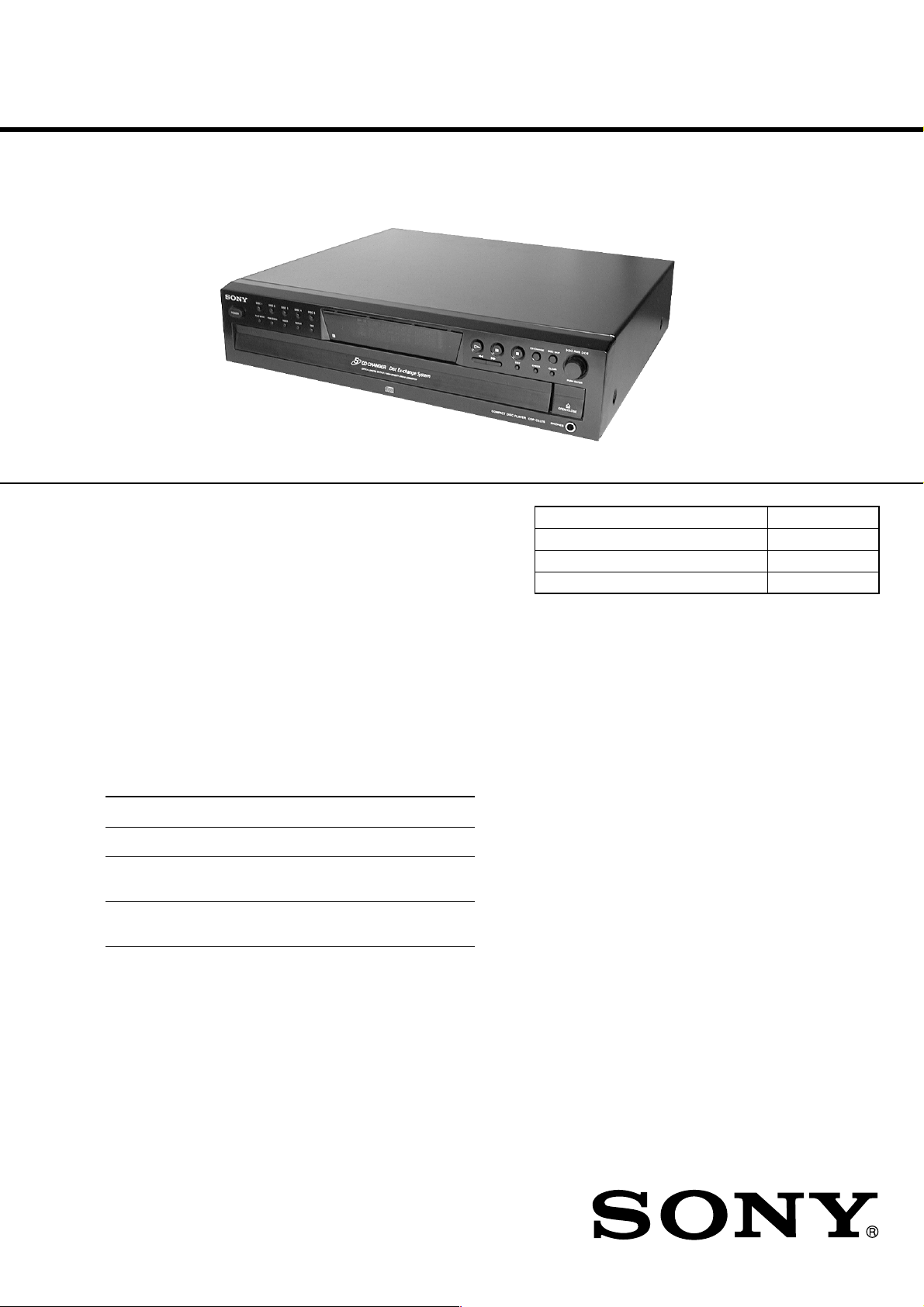
CDP-CE275/CE375
SERVICE MANUAL
Ver 1.1 2001.07
Photo: CDP-CE375
US Model
Canadian Model
Australian Model
CDP-CE275/CE375
AEP Model
UK Model
E Model
CDP-CE375
Model Name Using Similar Mechanism CDP-CE345
CD Mechanism Type CDM59-5BD27
Base Unit Name BU-5BD27
Optical Pick-up Name PXR-104X
Compact disc player
Laser Semiconductor laser ( λ = 780 nm)
Emission duration : continuous
Frequency response 2 Hz to 20 kHz ± 0.5 dB
Dynamic range More than 93 dB
Harmonic distortion Less than 0.0045%
Outputs
Jack Maximum Load
type output level impedance
ANALOG Phono 2 V Over 10
OUT jacks (at 50 kilohms) kilohms
DIGITAL Optical –18 dBm Wave
OUT output length:
(OPTICAL) connector 660 nm
PHONES Stereo 10 mW 32 ohms
(CDP-CE375 phone
only) jack
SPECIFICATIONS
General
Power requirements 120 V AC, 60 Hz
Power consumption 11 W
Dimensions (approx.) 430 x 110 x 400 mm
(w/h/d) (17 x 4 3/8 x 15 3/4 in.)
incl. projecting parts
Mass (approx.) 5 kg (11 lbs 1 oz)
Supplied accessories
Audio cord (2 phono plugs – 2 phono plugs) (1)
Remote commander (remote) (1) (CDP-CE375 only)
R6 (size AA) batteries (2) (CDP-CE375 only)
Design and specifications are subject to change without notice.
9-873-822-12 Sony Corporation
2001G0500-1 Home Audio Company
C 2001.7 Shinagawa Tec Service Manual Production Group
COMPACT DISC PLAYER
CDP-CE275/CE375
Ver 1.1 2001.07
TABLE OF CONTENTS
1. SERVICING NOTES ............................................... 3
2. GENERAL ................................................................... 4
3. DISASSEMBLY ......................................................... 5
4. TEST MODE.............................................................. 10
5. ELECTRICAL ADJUSTMENTS......................... 13
6. DIAGRAMS
6-1. Note for Printed Wiring Boards
and Schematic Diagrams ................................................ 15
6-2. Printed Wiring Board – BD Board – ............................. 16
6-3. Schematic Diagram – BD Board – ................................ 17
6-4. Printed Wiring Boards – JUNCTION/SENSOR/
LOADING MOTOR Boards – ........................................ 18
6-5. Schematic Diagram – JUNCTION/SENSOR/
LOADING MOTOR Boards – ........................................ 19
6-6. Printed Wiring Board – MAIN Board – ........................ 20
6-7. Schematic Diagram – MAIN Board –........................... 21
6-8. Printed Wiring Boards – PANEL Section – .................. 22
6-9. Schematic Diagram – PANEL Section –....................... 23
6-10. IC Pin Function Description ........................................... 26
SAFETY CHECK-OUT
After correcting the original service problem, perform the following safety check before releasing the set to the customer:
Check the antenna terminals, metal trim, “metallized” knobs,
screws, and all other exposed metal parts for AC leakage.
Check leakage as described below.
LEAKAGE TEST
The AC leakage from any exposed metal part to earth ground and
from all exposed metal parts to any exposed metal part having a
return to chassis, must not exceed 0.5 mA (500 microamperes.).
Leakage current can be measured by any one of three methods.
1. A commercial leakage tester, such as the Simpson 229 or RCA
WT -540A. Follow the man ufacturers’ instructions to use these
instruments.
2. A battery-operated A C milliammeter. The Data Precision 245
digital multimeter is suitable for this job.
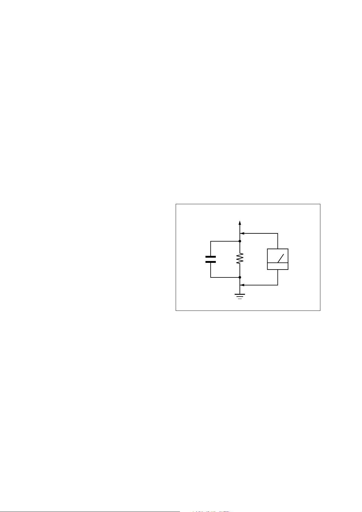
3. Measuring the voltage drop across a resistor by means of a
VOM or battery-operated AC voltmeter. The “limit” indication is 0.75 V, so analog meters must have an accurate lowvoltage scale. The Simpson 250 and Sanwa SH-63T rd are e xamples of a passive VOM that is suitable. Nearly all battery
operated digital multimeters that have a 2 V A C range are suitable. (See Fig. A)
To Exposed Metal
Parts on Set
7. EXPLODED VIEWS ................................................ 30
8. ELECTRICAL PARTS LIST ............................... 35
SAFETY-RELATED COMPONENT WARNING!!
COMPONENTS IDENTIFIED BY MARK 0 OR DOTTED
LINE WITH MARK 0 ON THE SCHEMATIC DIAGRAMS
AND IN THE PARTS LIST ARE CRITICAL TO SAFE
OPERATION. REPLACE THESE COMPONENTS WITH
SONY PARTS WHOSE PART NUMBERS APPEAR AS
SHOWN IN THIS MANUAL OR IN SUPPLEMENTS PUBLISHED BY SONY.
AC
1.5 k
0.15 µF
Fig. A. Using an AC voltmeter to check AC leakage.
Ω
Earth Ground
voltmeter
(0.75 V)
ATTENTION AU COMPOSANT AYANT RAPPORT
LES COMPOSANTS IDENTIFIÉS P AR UNE MARQUE 0
SUR LES DIAGRAMMES SCHÉMA TIQUES ET LA LISTE
DES PIÈCES SONT CRITIQUES POUR LA SÉCURITÉ
DE FONCTIONNEMENT. NE REMPLACER CES COMPOSANTS QUE PAR DES PIÈCES SONY DONT LES
NUMÉROS SONT DONNÉS DANS CE MANUEL OU
DANS LES SUPPLÉMENTS PUBLIÉS PAR SONY.
À LA SÉCURITÉ!
2
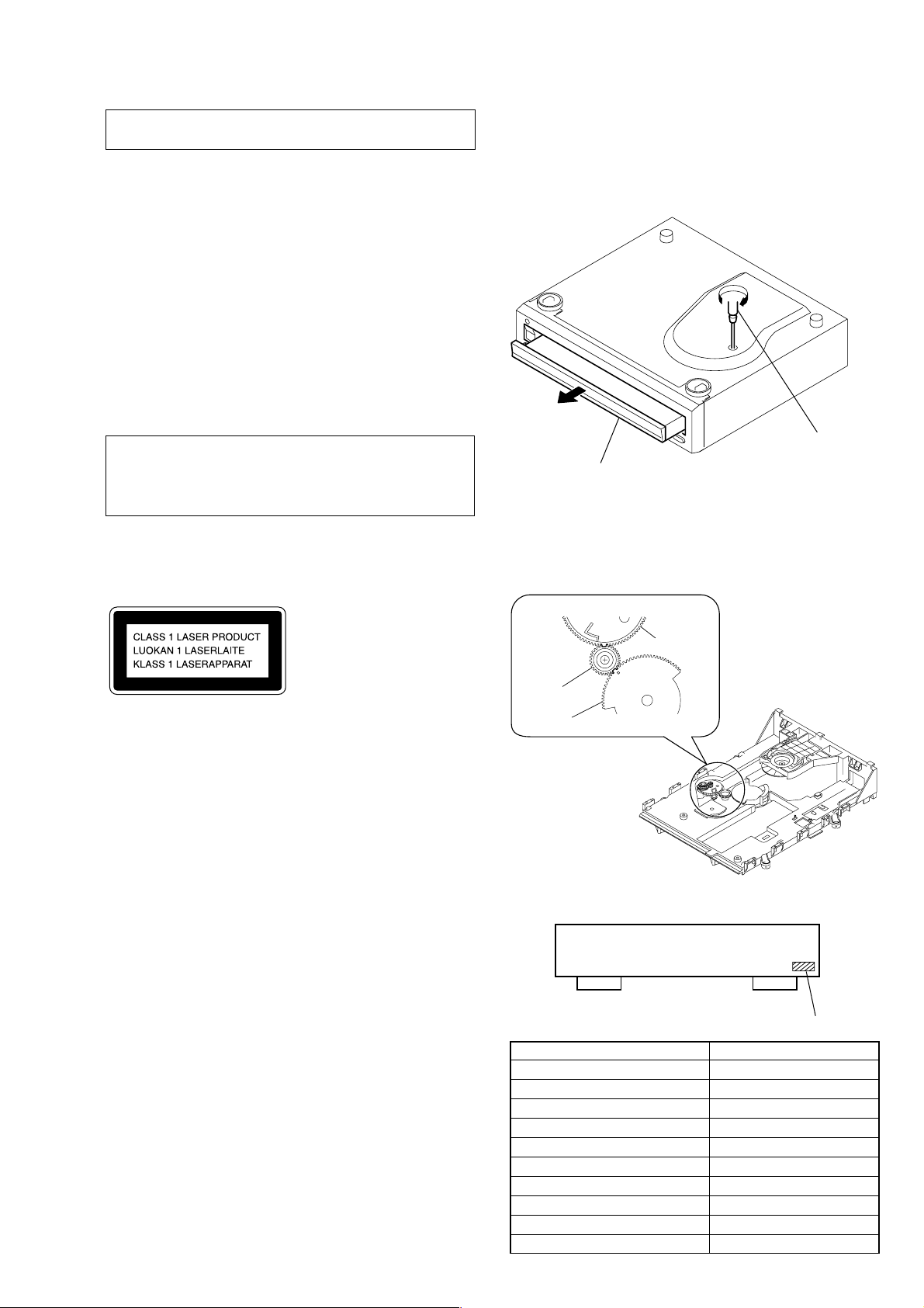
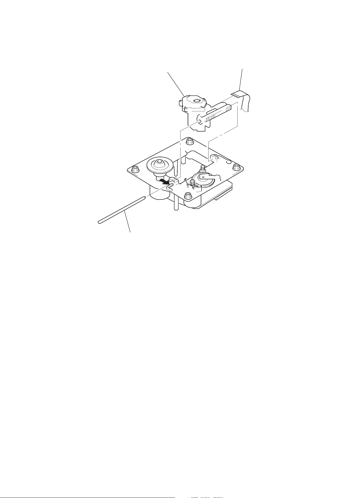
SECTION 1
table
tapering driver
*To close the disc table, turn the tapering
driver in the reverse direction (to IN direction).
gear (U/D)
gear (RV)
gear, swing
SERVICING NOTES
CDP-CE275/CE375
NOTES ON HANDLING THE OPTICAL PICK-UP
BLOCK OR BASE UNIT
The laser diode in the optical pick-up block may suffer electrostatic break-down because of the potential difference generated
by the charged electrostatic load, etc. on clothing and the human
body.
During repair, pay attention to electrostatic break-down and also
use the procedure in the printed matter which is included in the
repair parts.
The flexible board is easily damaged and should be handled with
care.
NOTES ON LASER DIODE EMISSION CHECK
The laser beam on this model is concentrated so as to be focused
on the disc reflective surface by the objective lens in the optical
pick-up block. Therefore, when checking the laser diode emission, observe from more than 30 cm away from the objective lens.
CAUTION
Use of controls or adjustments or performance of procedures
other than those specified herein may result in hazardous radiation exposure.
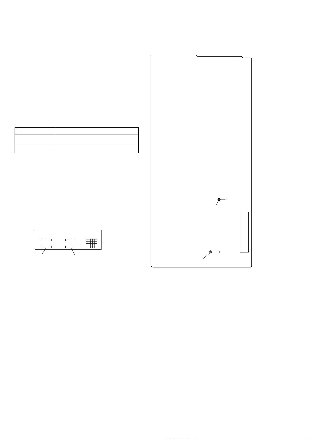
This appliance is classified as a CLASS 1 LASER product.
The CLASS 1 LASER PRODUCT MARKING is located on
the rear exterior.
HOW T O OPEN THE DISC T ABLE WHEN PO WER
SWITCH TURNS OFF
Insert a tapering driver into the aperture of the unit bottom, and
turn it in the direction of the arrow (to OUT direction).
NOTE FOR MAIN GEAR INSTALLATION
LASER DIODE AND FOCUS SEARCH OPERATION
CHECK
Carry out the “S curve check” in “CD section adjustment” and
check that the S curve waveforms is output three times.
Notes on chip component replacement
• Never reuse a disconnected chip component.
• Notice that the minus side of a tantalum capacitor may be damaged by heat.
Flexible Circuit Board Repairing
• Keep the temperature of the soldering iron around 270 ˚C during repairing.
• Do not touch the soldering iron on the same conductor of the
circuit board (within 3 times).
• Be careful not to apply force on the conductor when soldering
or unsoldering.
MODEL IDENTIFICATION
– BACK PANEL –
Part No.
Model Part No.
CDP-CE275: US model 4-233-719-0s
CDP-CE275: Canadian model 4-233-719-1s
CDP-CE275: Australian model 4-233-719-2s
CDP-CE375: US model 4-233-718-0s
CDP-CE375: Canadian model 4-233-718-1s
CDP-CE375: AEP model 4-233-718-2s
CDP-CE375: UK model 4-233-718-3s
CDP-CE375: Australian model 4-233-718-4s
CDP-CE375: E model 4-233-718-5s
CDP-CE375: Singapore model 4-233-718-6s
3
CDP-CE275/CE375
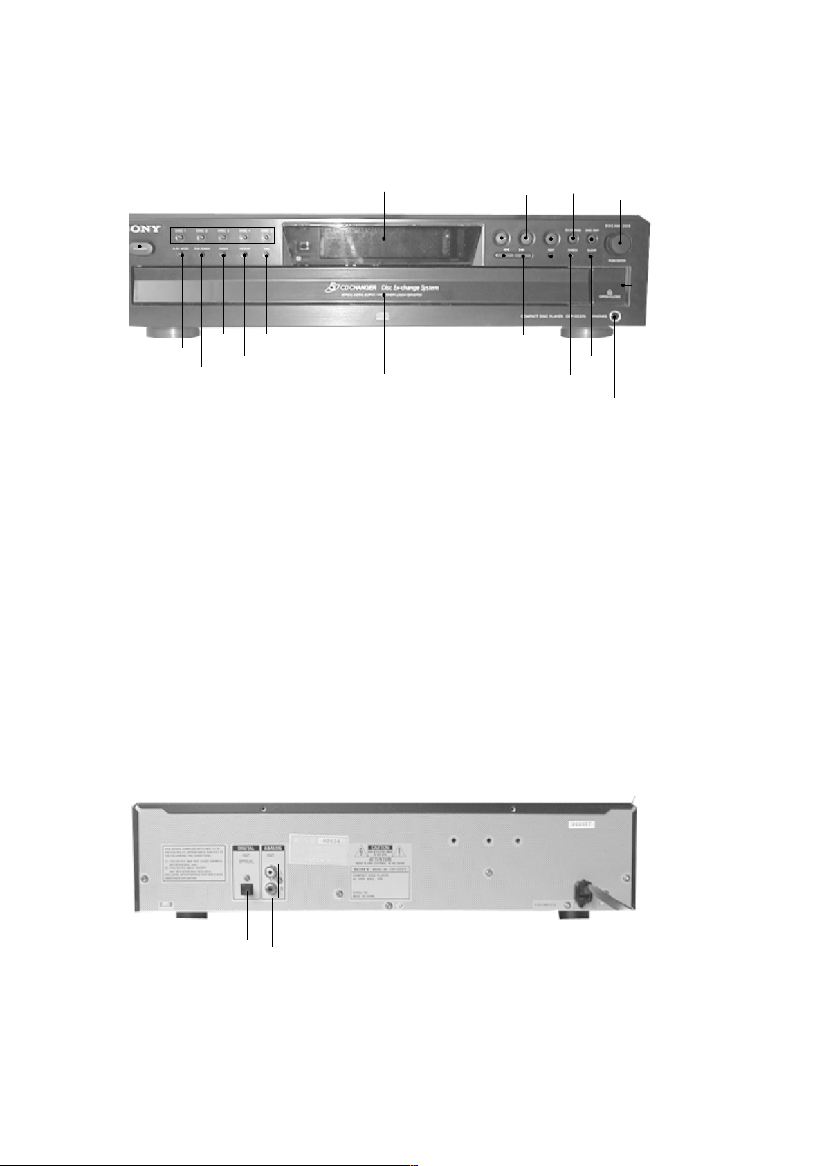
• LOCATION OF CONTROLS
– Front panel –
SECTION 2
GENERAL
1
2
w;
ws
wa
1 POWER button
2 DISC1 – DISC5 button
3 Fluorescent indicator tube display
4 H button
5 X button
6 x button
7 EX-CHANGE button
8 DISC SKIP button
9 l AMS L control
0 A OPEN/CLOSE button
qa PHONES jack
ql
qk
3
qj
qs CLEAR button
qd CHECK button
qf EDIT button
qg M button
qh m button
qj Disc table
qk TIME button
ql REPEAT button
w; FADER button
wa PEAK SEARCH button
ws PLAY MODE button
4
qh
5
qg
6
qf
7
qd
8
qs
9
0
qa
– Rear panel –
1
1 DIGITAL OUT OPTICAL connector
2 ANALOG OUT
4
2
• The equipment can be removed using the following procedure.
CDP-CE275/CE375
SECTION 3
DISASSEMBLY
Set Case Front Panel Assy
Base Unit (BU-5BD27) Optical Pick-up
Tray, Table Assy
Note: Follow the disassembly procedure in the numerical order given.
CD Mechanism Block
Sensor Board
Jnuction Board, Loading Motor Board
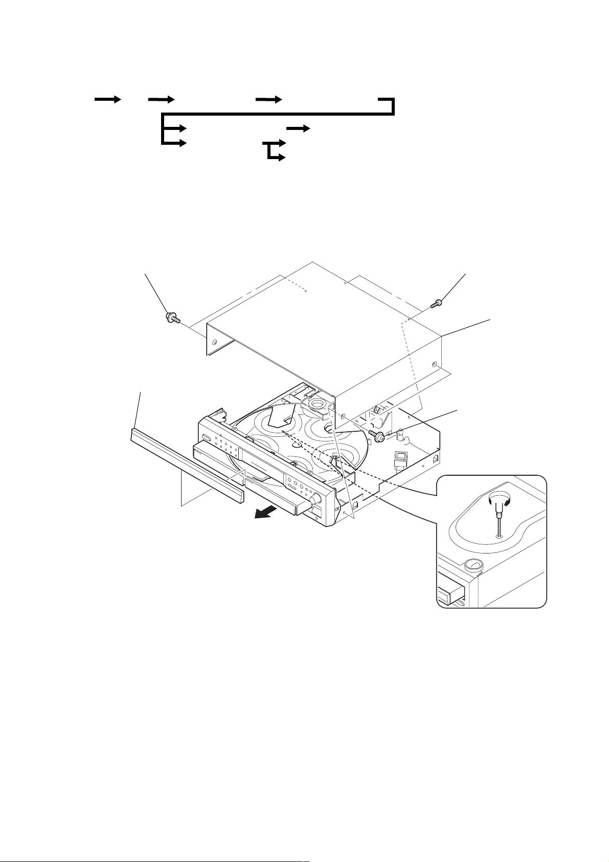
3-1. CASE
two screws
2
(case 3TP2)
7
panel, loading
3
two screws
(BVTP 3x8)
4
case
6
1
two screws
(case 3TP2)
5
5
CDP-CE275/CE375
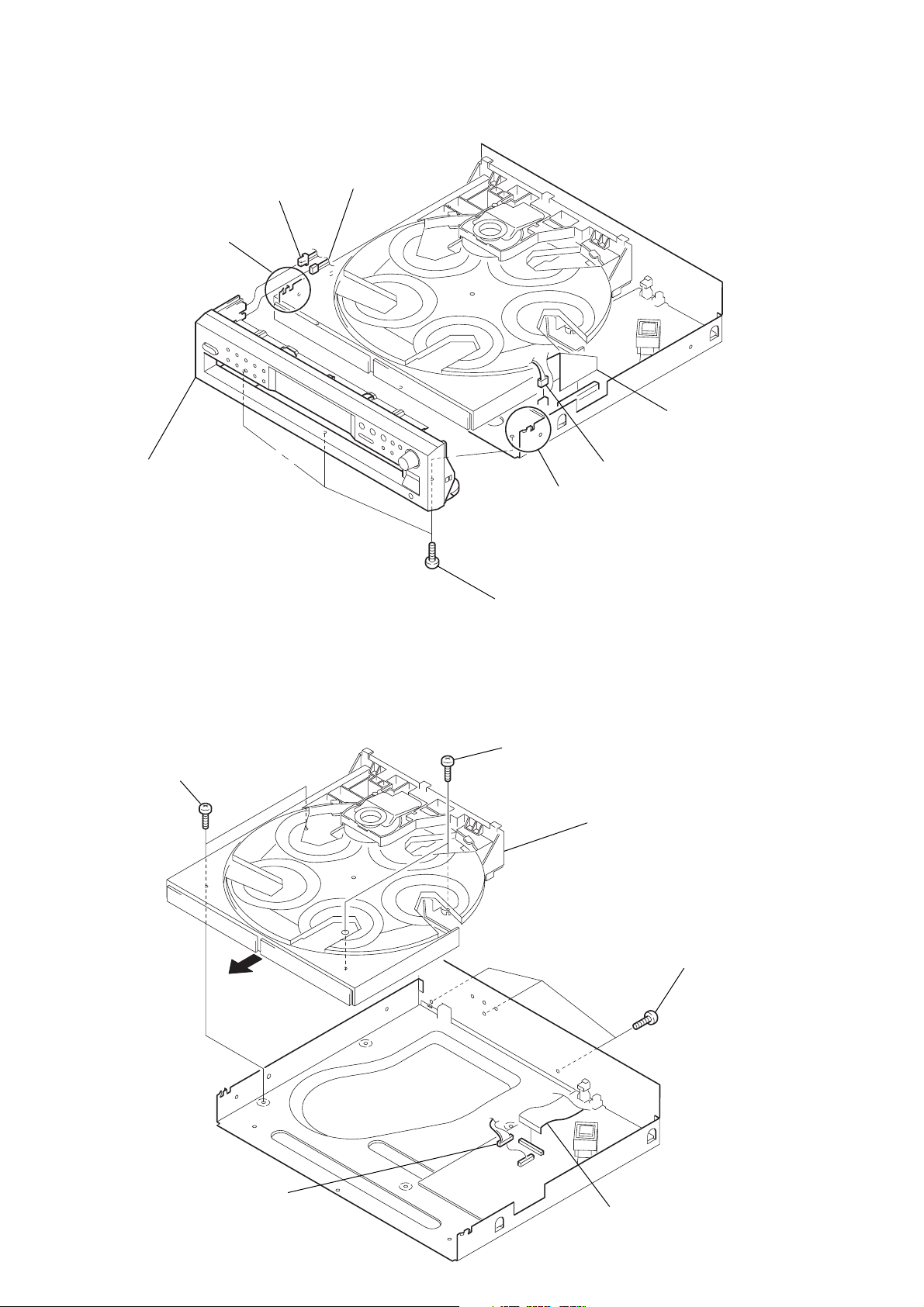
3-2. FRONT PANEL ASSY
7 claw
8 front panel assy
1 CN601
2 CN602
3 CN301
4 CN351
6 claw
5 three screws
(BVTP 3x8)
3-3. CD MECHANISM BLOCK (CDM59-5BD27)
4 two screws
(BVTP 3x8)
5 tray
6 two screws
(BVTP 3x8)
7 CDM59-5BD27
3 three screws
(BVTP 3x8)
2 CN311
1 CN302
6
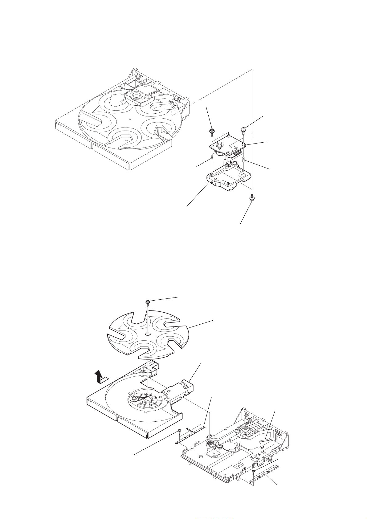
3-4. BASE UNIT (BU-5BD27)
P
3 two screws
(+PTPWHM 2.6),
floating
CDP-CE275/CE375
2 two screws
(+PTPWHM 2.6), floating
7 base unit (BU-5BD27)
3-5. TRA Y , T ABLE ASSY
6 spring (932),
compression
4 holder (BU) assy
8 screw
(+PTPWHM 2.6), floating
5 spring (932),
compression
1 two screws
(+PTPWHM 2.6), floating
9 tray
5
1 two screws
(M 2.6), +BTTP
7 table assy
2 bracket (guide)
6 CN15
3 three screws
(M 2.6), +BTT
4 bracket (guide)
7
CDP-CE275/CE375
d
d
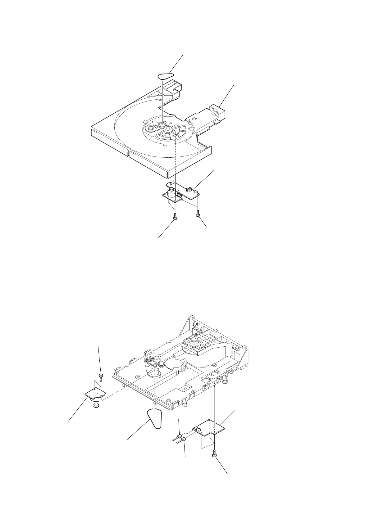
3-6. SENSOR BOARD
1 belt (rotary)
table assy
4 SENSOR boar
3 two screws
3-7. JUNCTION BO ARD , LO ADING MOTOR BOARD
6 two screws
(M 2.6), +BTTP
7 LOADING MOTOR board
2 two screws
(M 2.6), +BTTP
(M 2.6), +BTTP
4 JUNCTION boar
2 CN13
5 belt (loading)
1 CN14
3 three screws
(M 2.6), +BTTP
8
3-8. OPTICAL PICK-UP
r
CDP-CE275/CE375
2 shaft, sled
3 optical pick-up
1
4 connecto
9
CDP-CE275/CE375
r
Ver 1.1 2001.07
SECTION 4
TEST MODE
ADJ MODE
NOTE:This mode cannot be performed without a general remote com-
mander.
1. Chuck the CD first, and then turn OFF the power.
2. Short-circuit the test point TP1 (ADJ) of the MAIN board and
ground with a lead wire.
3. Press the
The CD is playback automatically and the ADJ mode is set.
4. To exit the mode, press the
power.
• Prohibits high speed search during accessing
• Ignores even if GFS becomes “L”
ADJ Mode Special Function Table
PLAY MODE
EDIT RFCK → GFS → Error rate display
[POWER] button to turn ON the power.
[POWER] button to turn OFF the
Button Function
Auto gain display
(Focus, Tracking and Sledding)
FLUORESCENT INDICATOR TUBE ALL LIT, AND
KEY CHECK MODE
1. Short-circuit the test TP2 (AFADJ) of the MAIN board and
ground with a lead wire.
2. Press the [POWER] button to turn ON the power.
The whole fluorescent indicator tube lights up.
3. All buttons have individual button numbers.
When a button is pressed, the button number is counted up
and displayed.
Connecting Location:
– MAIN BOARD (Component Side) –
JW66
TP1 (ADJ)
CN301
10
Count up display Displays button numbe
When remote controller signals are received, “RM **” will be
displayed.
(** are the numbers corresponding to the remote controller
buttons.)
When using the remote controller, switch the [CD1/2/3] switch
to CD1.
4. To exit the mode, press the [POWER] button to turn OFF the
power.
JW68
TP2 (AFADJ)
10
Buttons and Corresponding Button Numbers
1
SECSTEPMINPEAKTRACKDISC
2345
678910
11 12 13 14 15
16 17 18 19 20
ALL1DISCS
PROGRAM
SHUFFLE
REPEAT 1
EDIT
TIME
FADE
A B
All lit
1
STEPPEAKDISC
2345
678
ALL1DISCS
Button Button Number or Display
DISC1 12
DISC2 11
DISC3 10
DISC4 9
DISC5 8
PLAY MODE 20
PEAK SEARCH 19
FADER 18
REPEAT 17
TIME 16
H (PLAY) Partial lighting 1
X (PAUSE) Partial lighting 2
x (STOP) All lit
EX-CHANGE 35
DISC SKIP 36
m 24
M 25
EDIT 26
CHECK 27
CLEAR 28
AMS (push) 37
When rotated clockwise: The music calendar
AMS (turn)
numerals light up in ascending order.
When rotated counterclockwise: The music
calendar numerals light up in descending
order.
Partial lighting 1
Partial lighting 2
CDP-CE275/CE375
Ver 1.1 2001.07
SECMINTRACK
R
Light altemately
r
135
79
11 13 15
18 20
R
Light altemately
r
24
6810
12 14
16
19
17
11
CDP-CE275/CE375
Ver 1.1 2001.07
AGING MODE
For the aging mode, three modes of all mode, disc table mode, and loading mode are available.
This set has the Aging mode for operation check of the mechanism deck.
• If a failure occurred
The aging operation stops and a faulty status is displayed on the fluorescent indicator tube.
• If no failure occurs
The aging operation continues repeatedly.
Note: Do not use the test disc when performing aging.
Aging will not be performed properly if discs with tracks shorter than 4 seconds are used.
Procedure:
1. Press the [POWER] button and turn ON the power.
2. Set discs on all trays.
(More than two discs if five are not available)
3. All mode:
Press the [CHECK], [PLAY MODE] and x buttons at the same time.
Disc table mode:
Press the [CHECK], [PLAY MODE] and [SKIP] buttons at the same time.
Loading mode:
Press the [CHECK], [PLAY MODE] and [EX-CHANGE] buttons at the same time.
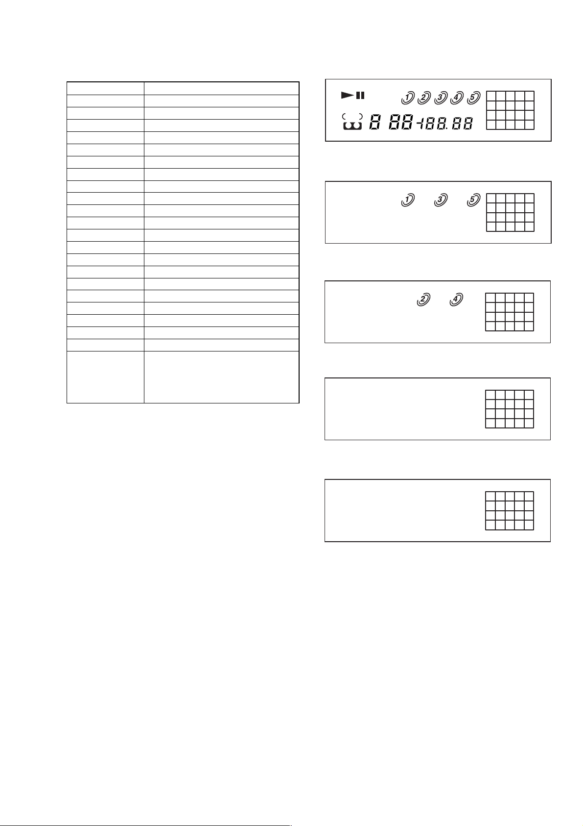
4. Aging starts, and the fluorescent indicator tube will display the following.
5. To exit the mode, press the [POWER] button to turn OFF the power.
Code No. Status All mode
0 CLOSE (Tray closed) a a A-0 Err 0
1 TOC reading aa a A-1 Err 1
2 Access to last track a A-2 Err 2
3 Play of last track (3 sec) a Counter display Err 3
4 EX OPEN (Tray opened while chucking) a a A-4 Err 4
5 EX SKIP (Disc tray rotated) a A-5 Err 5
6 EX CLOSE (Tray closed) a a A-6 Err 6
7 Access to first track a A-7 Err 7
8 Play of first track (3 sec) a Counter display Err 8
9 OPEN (tray opened) a a A-9 Err 9
DISC SKIP (Disc tray rotated,
A
and next disc was selected)
aa A-A Err A
Disc table Loading Display in Display in
mode mode Normal operation case of failure
The discs are selectie in the order of DISC1 →DISC2 → DISC3 → DISC4 → DISC5 → DISC1 → .... Empty trays are skipped.
But the order is random in the disc table mode.
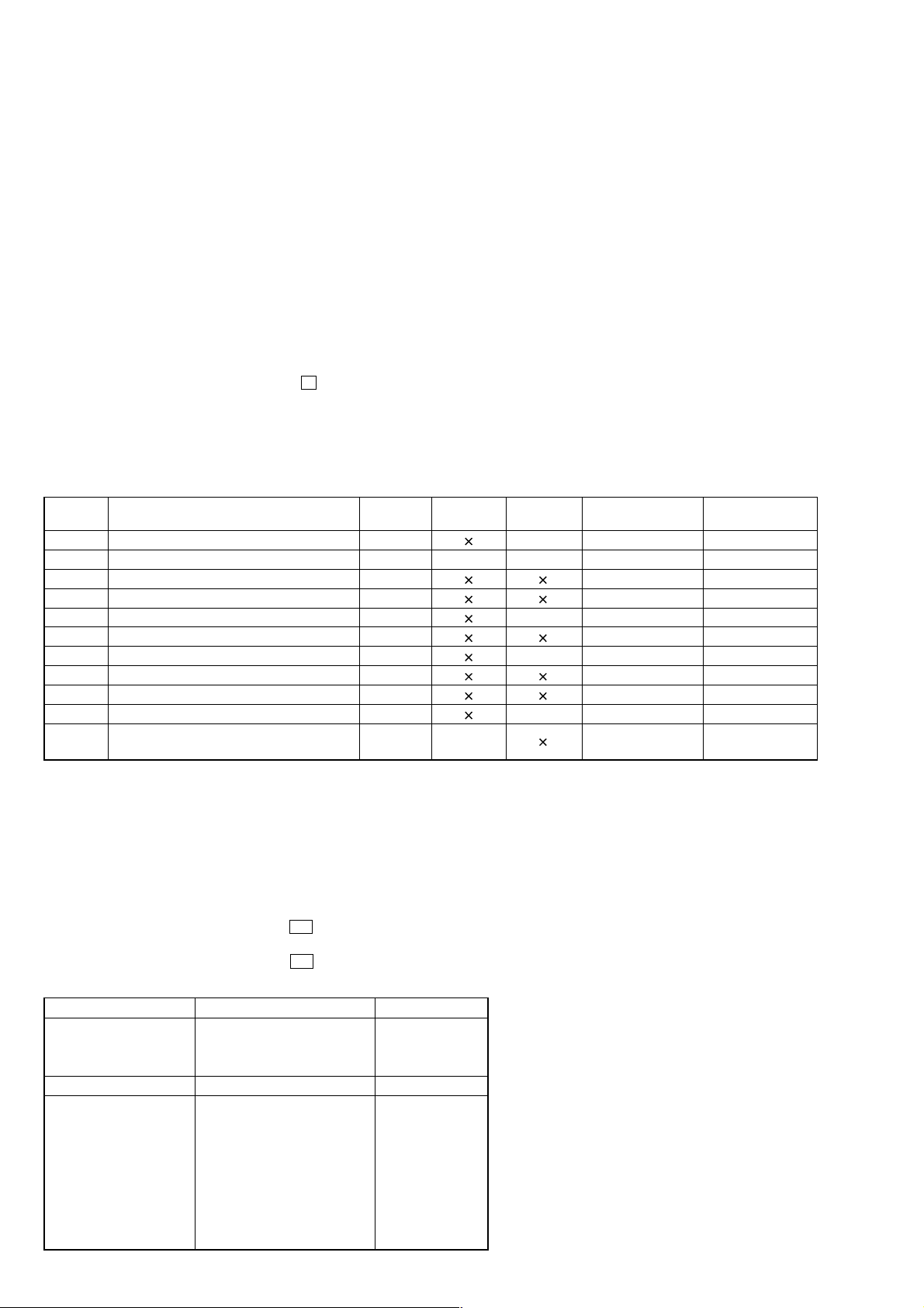
MECHANISM DECK CHECK MODE
For the mechanism deck check mode, two modes of disc table mode and loading mode are available.
In the mechanism deck check mode, the disc table turning time and the loading time in each section are measured and displayed.
Procedure:
Disc table mode:
Press the [POWER] switch while pressing H , [ OPEN/CLOSE] and [REPEAT] buttons simultaneously.
Loading mode:
Press the [POWER] switch while pressing H , [ OPEN/CLOSE] and [TIME] buttons simultaneously.
Display contents
Mode Check command Display
Disc table mode 0: Right one turn r 12.5
Table turning 1: Left one Turn L 10.2
(
time measurement
Table mode
Loading time
(
measurement
)
2: Measurement end r 12.5
3: Undefined
4: Star position Sta – –.–
5: Open → Close CLo 10.2
6: Close → BU up UP 0.7
7: BU up → EX open EoP 6.2
)
8: EX open → EX close ECL 10.3
9: EX close → BU down don 1.2
A: BU down → Open oPn 9.3
FF: Measurement end CLo 10.2
A
A
12
 Loading...