

Sony CCD-TRV21E, CCD-TRV21, CCD-TRV21PK, B Mechanism Operation Manual
Video8
B MECHANISM
OPERATION
MANUAL
A18
m MECHANISMDECK

CONTENTS
1. Main parts layout diagram ....................................................................... 4
2. Operation of main parts ............................................................................ 5
3. Operation of each part .............................................................................. 6
3-1. Driving of LS chassis ......................................................................................... 6
3-2. Driving of pinch roller ....................................................................................... 8
3-3. Driving of tension regulator and TG1 ............................................................ 10
3-4. Driving of S reel and S ratchet ....................................................................... 12
3-5. Driving of T ratchet and T soft gear .............................................................. 14
4. Operation in each mode .......................................................................... 17
4-1. Cassette IN =====:=_ STOP ............................................................................. 17
4-2.
4-3.
4-4.
4-5.
4-6.
4-7.
4-8.
4-9.
STOP _ PB ............................................................................................ 23
STOP =:=:===_ REC ......................................................................................... 27
STOP ====:==_ FF ............................................................................................ 31
STOP =====_ REWIND ................................................................................ 35
PB ===:==_ CUE .............................................................................................. 38
PB ==:===_ REVIEW ...................................................................................... 40
PB _ PAUSE ......................................................................................... 42
STOP ===:=:=_ EJECT .................................................................................... 45
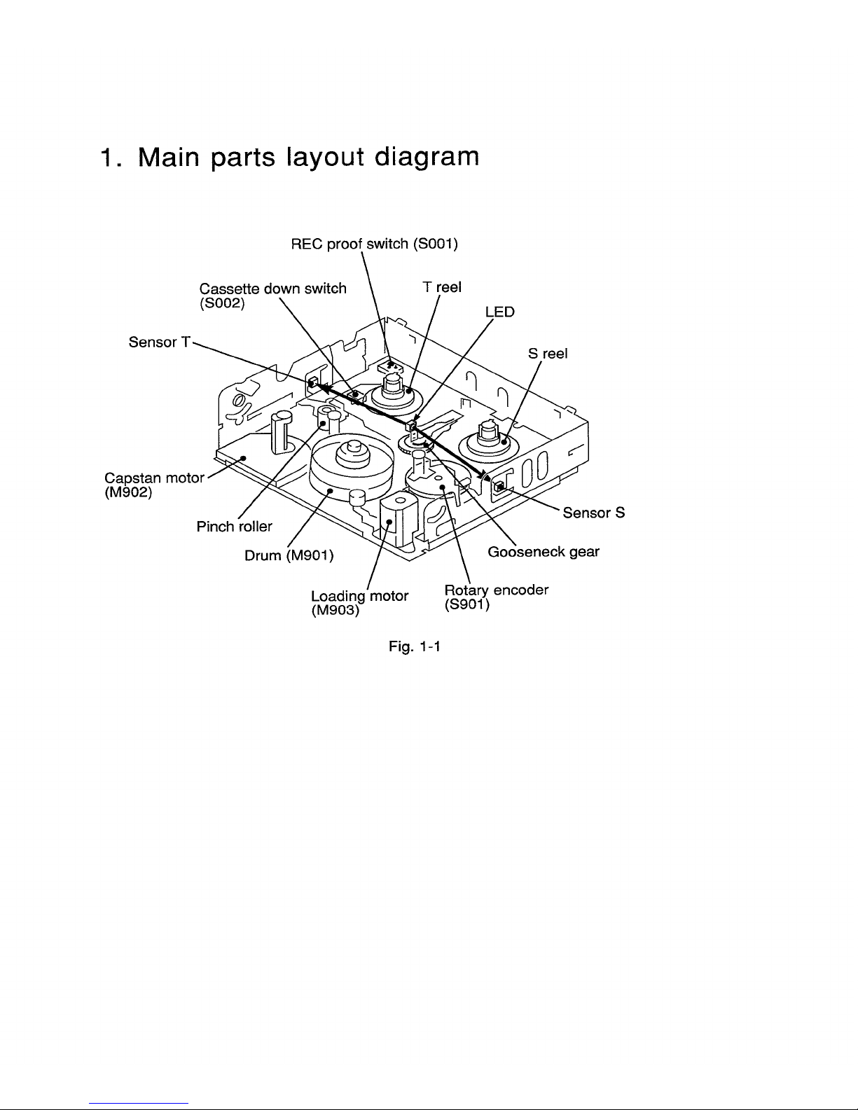
1. Main parts layout diagram
REC proof switch (S001)
Sensor
Cassette down switch
(S002)
T reel
LED
S reel
Capstan motor
(M902)
Pinch roller
Drum (M901)
Loading motor
(M903)
Sensor S
Gooseneck gear
Rotary encoder
(S901)
Fig. 1-1
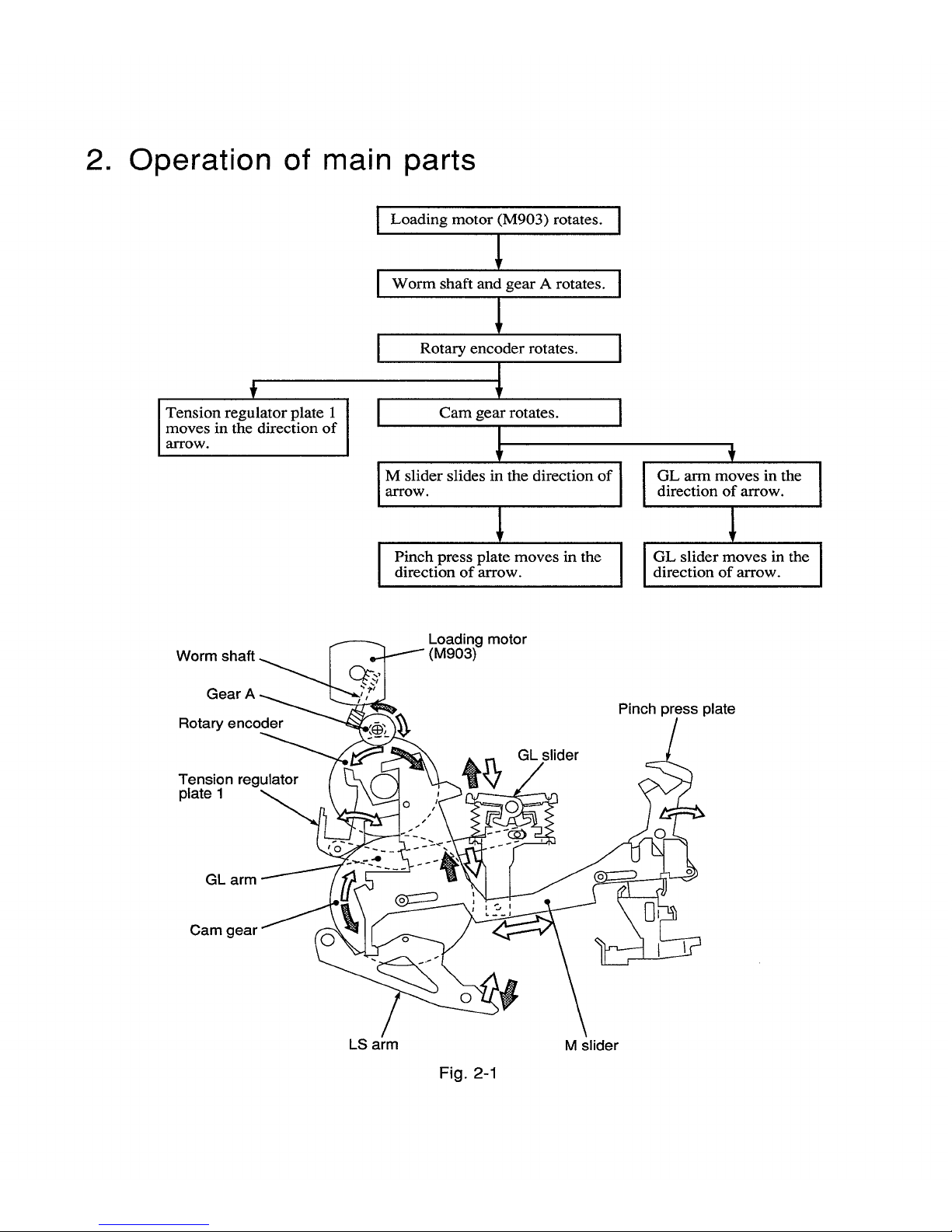
2. Operation of main parts
Tension regulator plate 1
moves in the direction of
arrow.
Loading motor (M903) rotates. ]
[ Worm shaft and gear A rotates. [
[ Rotary encoder rotates. [
[ Cam gear rotates. [
M slider slides in the direction of [
arrow.
Pinch press plate moves in the ]
direction of arrow.
f
I L arm moves in the [
direction of arrow.
direction of arrow.
Worm
Loading motor
Gear
Rotary encoder
Tension regulator
plate 1
GL slider
Pinch press plate
GL arm
Cam gear
LS arm
Fig. 2-1
M slider
3. Operation of each part
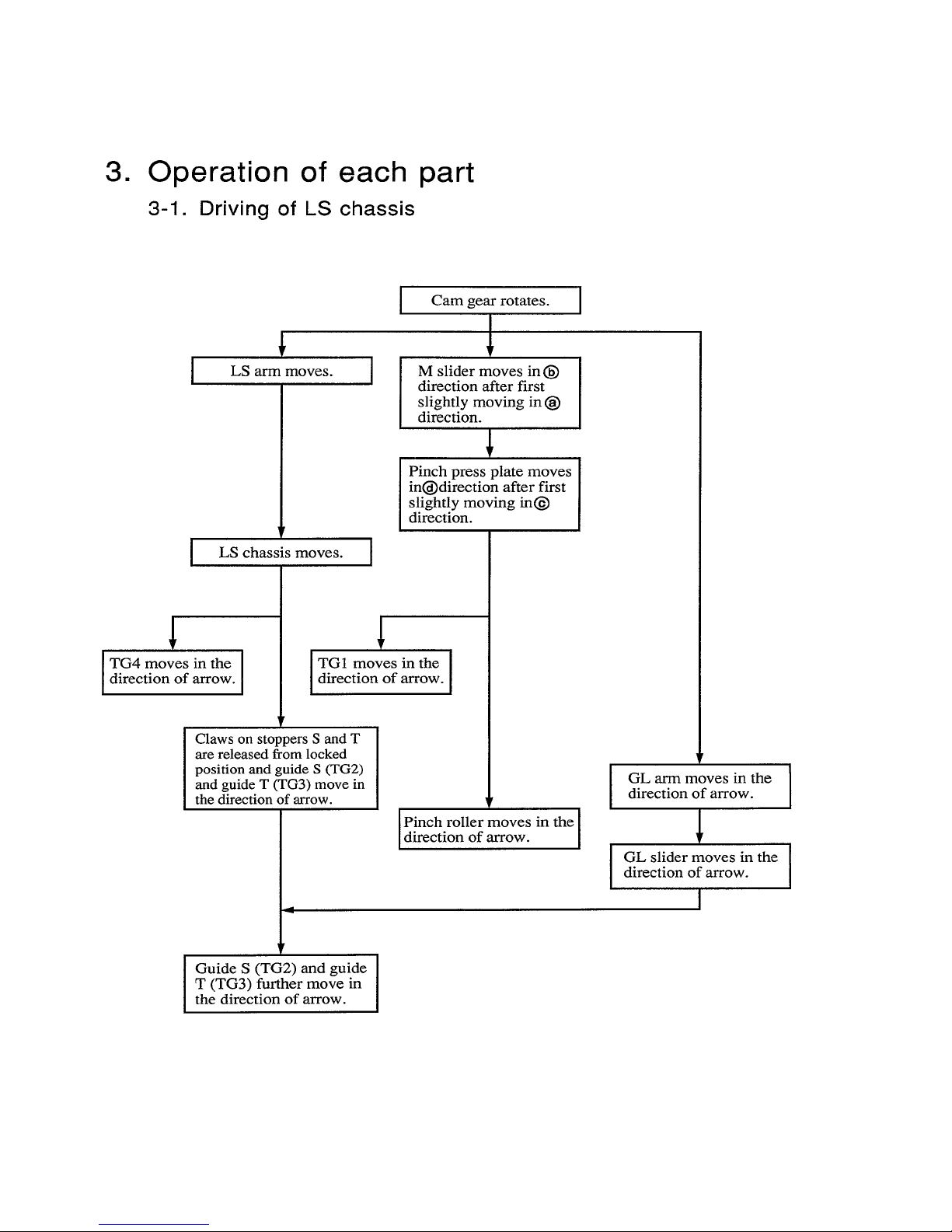
3-1. Driving of LS chassis
1
I
i
TG4 moves in the |
direction of arrow.
J
LS arm moves.
r
LS chassis moves.
Cam gear rotates.
!
I M slider in
®moves
direction after first
slightly moving in O
direction.
Pinch press plate moves
inOdirection after first
slightly moving int_)
direction.
I
I
TG1 moves m the |
I
direction of arrow.
1
Claws on stoppers S and T
are released from locked
position and guide S (TG2)
and guide T (TG3) move in
the direction of arrow.
Pinch roller moves in theJ
direction of arrow.
GL arm moves in the
direction of arrow.
!
GL slider moves in the
direction of arrow.
I
I
Guide S (TG2) and guide
T (TG3) further move in
the direction of arrow.
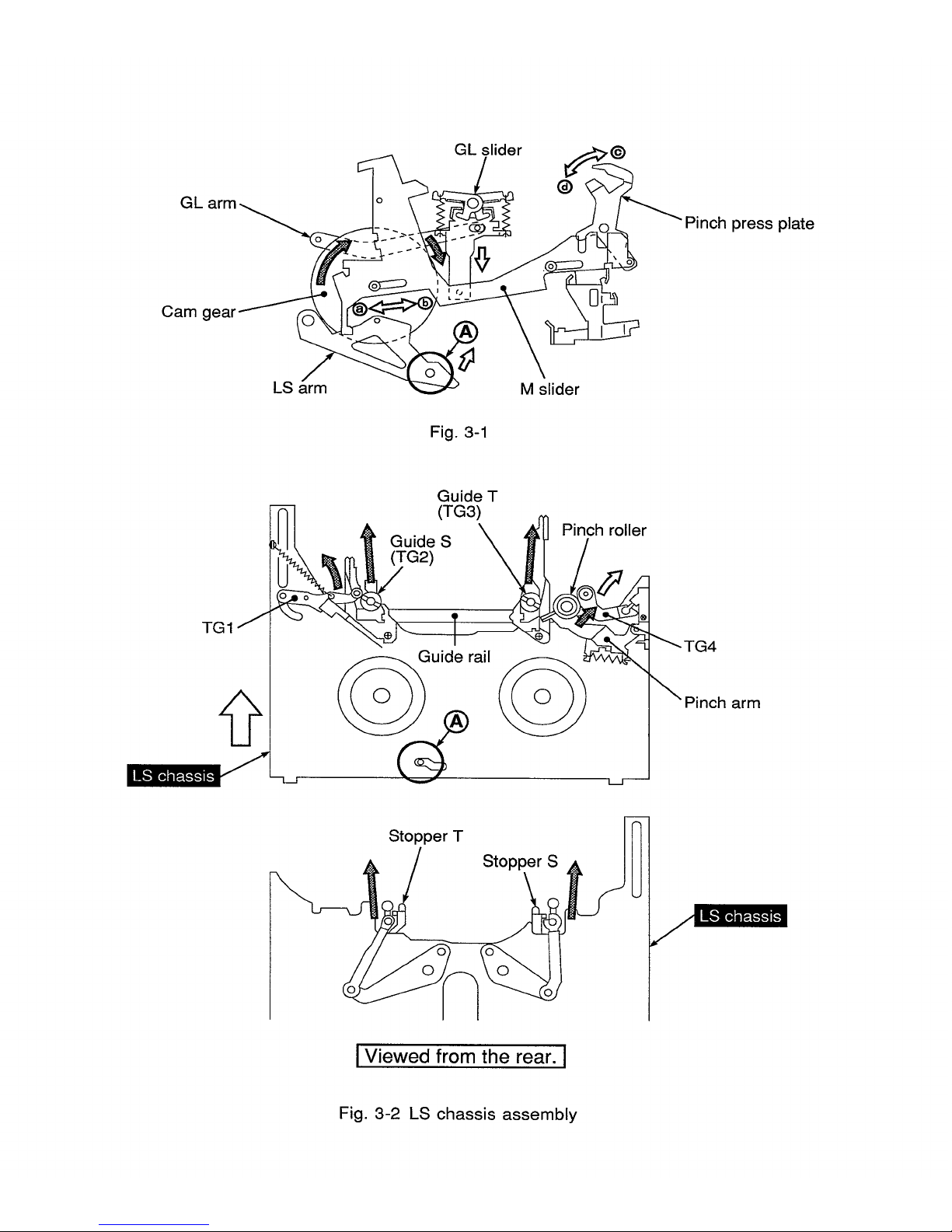
GL arm
GL slider
@
•Pinch press plate
Cam gea=
LS arm
M slider
Fig. 3-1
TG1
Guide T
(TG3)
Guide S
(TG2)
uide rail
Pinch roller
arm
Stopper T
Stopper S
IViewed from the rear. I
Fig. 3-2 LS chassis assembly
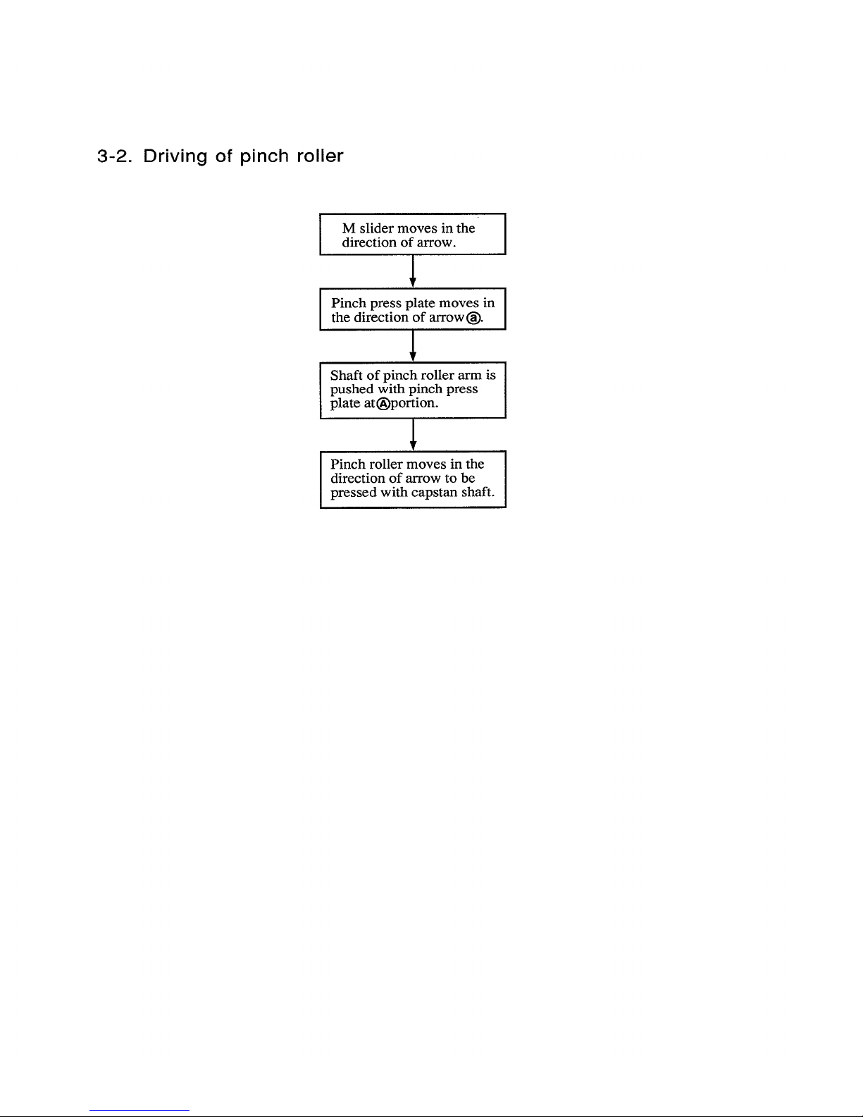
3-2. Driving of pinch roller
M slider moves in the
direction of arrow.
!
Pinch press plate moves in
the direction of arrow (_).
,!
Shaft of pinch roller arm is
pushed with pinch press
plate at!_)portion.
Pinch roller moves in the
direction of arrow to be
pressed with capstan shaft.
I
I
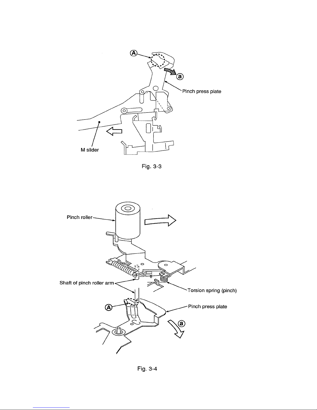
Pinch press plate
M slider
Fig. 3-3
Shaft of pinch roller
"-Torsion spring (pinch)
press plate
Fig. 3-4
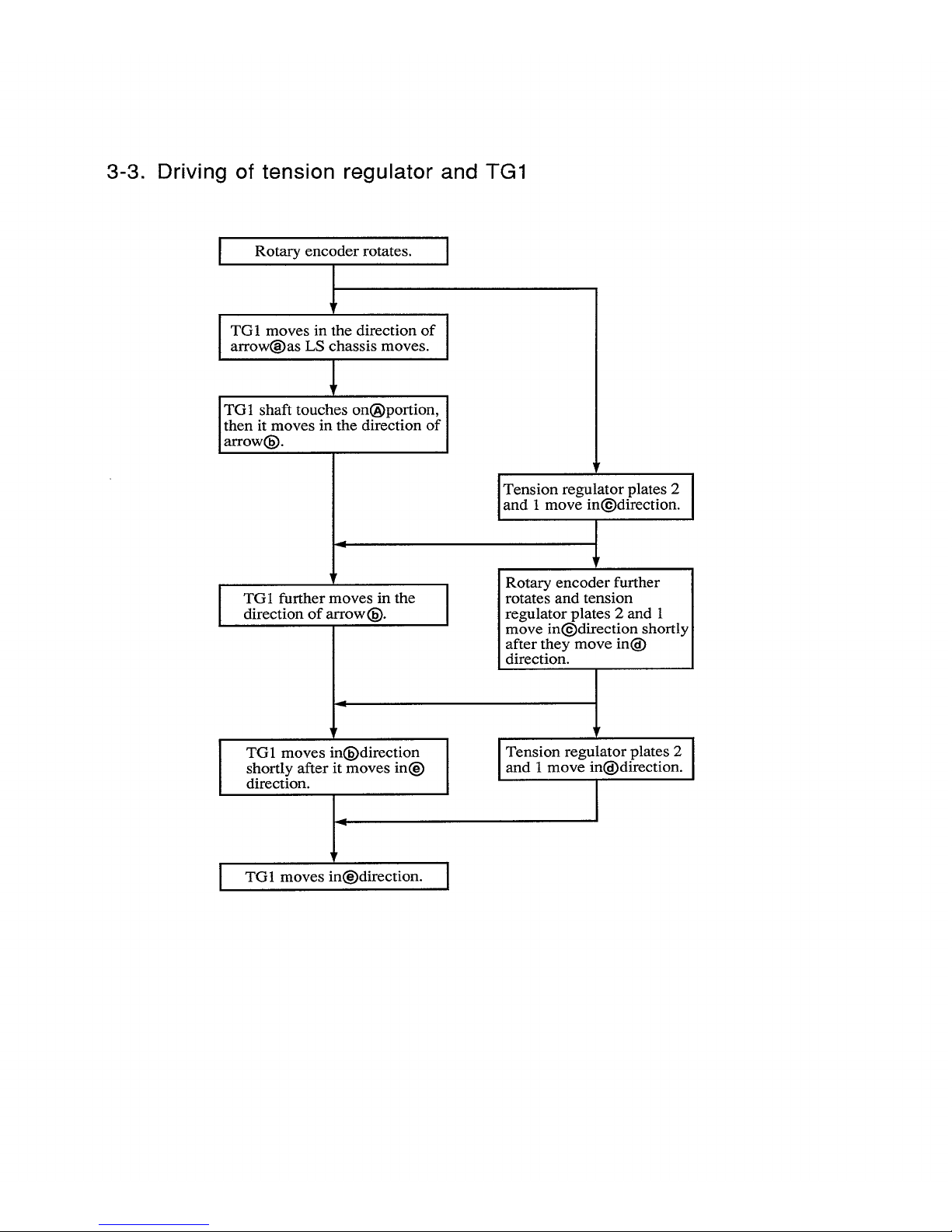
3-3. Driving of tension regulator and TG1
Rotary encoder rotates. [
|
TG1 moves in the direction of I
arrowf_)as LS chassis moves.
I
TG1 shaft touches on!_)portion, I
then it moves in the direction of
1
arrow_.
I
!
TG1 further moves in the [
direction of arrow(fi).
I
!
TG1 moves in(_)direction I
shortly after it moves int_)
I
direction.
!"
TG1 moves inl_)direction. I
Tension regulator plates 2
I
and 1 move in@direction, i
|
!
Rotary encoder further ]
rotates and tension [
regulator plates 2 and 1 [
move in(_)direction shortly I
after they move in(_ ]
direction. [
!
I Tension regulator plates 2 I
and 1 move inl_)direction.
I
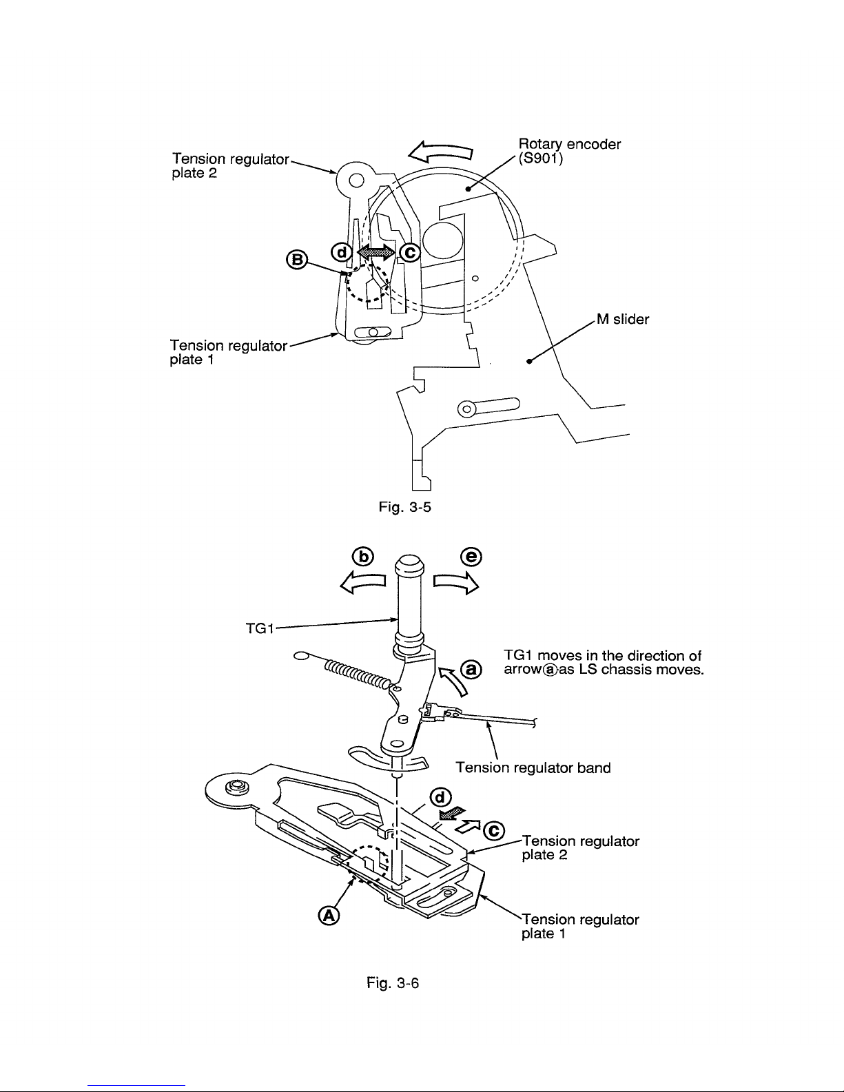
Tension reg
plate 2
Rotary encoder
(S901)
Tension regulator
plate 1
O
slider
Fig. 3-5
TG1 _1_(_ TG1 moves in the direction of
arrow(_as LS chassis moves.
Tension regulator band
regulator
plate 2
®
"-Tension regulator
plate 1
Fig. 3-6
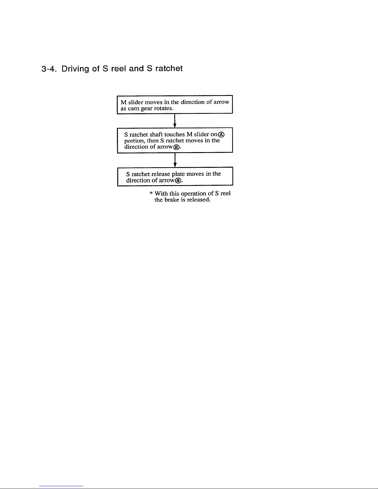
3-4. Driving of S reel and S ratchet
I M slider moves in the direction of arrow [
I
as cam gear rotates.
I
,L
1
S ratchet shaft touches M slider onl_
portion, then S ratchet moves in the
direction of arrowl_).
S ratchet release plate moves in the
direction of arrowt_).
* With this operation of S reel
the brake is released.
 Loading...