

Page 1
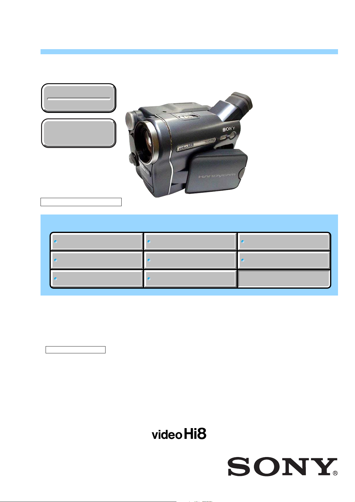
CCD-TRV128/TRV228/TRV228E/TRV328/TRV428/TRV428E
RMT-833
SERVICE MANUAL
US Model
Ver 1.1 2005.06
Revision History
Revision History
How to use
How to use
Acrobat Reader
Acrobat Reader
M2100/M2101 MECHANISM
North European Model
CCD-TRV128/TRV228/TRV228E/TRV328/TRV428E
Photo: CCD-TRV328
Canadian Model
CCD-TRV128/TRV328
AEP Model
East European Model
CCD-TRV228E/TRV428E
UK Model
CCD-TRV228E
E Model
Australian Model
Hong Kong Model
CCD-TRV428E
Argentine Model
Brazilian Model
CCD-TRV128
Tourist Model
CCD-TRV428/TRV428E
Link
Link
SPECIFICATIONS
SPECIFICATIONS
SERVICE NOTE
SERVICE NOTE
DISASSEMBLY
DISASSEMBLY
NTSC MODEL: CCD-TRV128/TRV228/TRV328/TRV428
PAL MODEL: CCD-TRV228E/TRV428E
•For ADJUSTMENTS (SECTION 6), refer to SERVICE MANUAL, ADJ (987629051.pdf).
• INSTRUCTION MANUAL is shown at the end of this document.
•For MECHANISM ADJUSTMENTS, refer to the “8mm Video MECHANICAL ADJUSTMENT MANUAL IX
M2000 MECHANISM ” (9-929-861-11).
• Reference No. search on printed wiring boards is available.
•Table for differences of function of each model.
•TO TAKE OUT A CASSETTE WHEN NOT EJECT (FORCE EJECT)
•When the machine needs to be repaired, make sure to follow the items of “LCD TYPE CHECK”.
• HELP: Sheet attachment positions and procedures of processing the flexible boards/harnesses are shown.
BLOCK DIAGRAMS
BLOCK DIAGRAMS
FRAME SCHEMATIC DIAGRAMS
FRAME SCHEMATIC DIAGRAMS
SCHEMATIC DIAGRAMS
SCHEMATIC DIAGRAMS
PRINTED WIRING BOARDS
PRINTED WIRING BOARDS
REPAIR PARTS LIST
REPAIR PARTS LIST
VIDEO CAMERA RECORDER
Page 2

CCD-TRV128/TRV228/TRV228E/TRV328/TRV428/TRV428E
S
SPECIFICATIONS
TM
SERIE
Video camera recorder
System
Video recording system
2 rotary heads, Helical scanning FM system
Audio recording system
Rotary heads, FM system
Video signal
CCD-TRV228E/428E:
PAL color, CCIR standards
CCD-TRV128/228/328/428:
NTSC color, EIA standards
Usable cassette
8 mm video format cassette
Tape speed
CCD-TRV228E/428E:
SP: Approx. 20.05 mm/s
LP: Approx. 10.06 mm/s
CCD-TRV128/228/328/428:
SP: Approx. 14.35 mm/s
LP: Approx. 7.19 mm/s
Recording/playback time (using 90 min. Hi8/
Digital8 video cassette)
CCD-TRV228E/428E:
SP: 1 h 30 min
LP: 3 h
Recording/playback time (using 120 min. Hi8/
Digital8 video cassette)
CCD-TRV128/228/328/428:
SP: 2 h
LP: 4 h
Fast forward/rewind time
(CCD-TRV228E/428E: using 90 min. Hi8/
Digital8 video cassette)
(CCD-TRV128/228/328/428: using 120 min.
Hi8/Digital8 video cassette)
Approx. 5 min
Viewfinder
Electric viewfinder (monochrome )
Image device
CCD-TRV228E/428E:
3.0 mm (1/6 type) CCD (Charge Coupled
Device)
Gross: Approx. 380 000 pixels
Effective: Approx. 230 000 pixels
CCD-TRV128/228/328/428:
3.0 mm (1/6 type) CCD (Charge Coupled
Device)
Gross: Approx. 320 000 pixels
Effective: Approx. 200 000 pixels
Lens
Combined power zoom lens
Filter diameter: 37 mm (1 1/2 in.)
20 × (Optical), 990 × (Digital)
F=1.6 - 2.4
Focal length
2.5 - 50 mm (1/8 - 2 in.)
When converted to a 35 mm still camera
42 - 840 mm (1 11/16 - 33 1/8 in.)
Color temperature
Auto
Minimum illumination
1 lx (lux) (F 1.6)
0 lx (lux) (in the NightShot plus mode)*
*Objects unable to be seen due to the dark can be
shot with infrared lighting.
Input/Output connectors
S video output
4-pin mini DIN
Luminance signal: 1 Vp-p, 75 Ω (ohms),
unbalanced
CCD-TRV228E/428E:
Chrominance signal: 0.3 Vp-p , 75 Ω (ohms),
unbalanced
CCD-TRV128/228/328/428:
Chrominance signal: 0.286 Vp-p, 75 Ω
(ohms), unbalanced
Audio/Video output
AV MINIJACK
Video signal: 1 Vp-p, 75 Ω (ohms),
unbalanced, sync negative
Audio signal: 327 mV (at output impedance
more than 47 kΩ (kilohms)), Output
impedance with less than 2.2 kΩ (kilohms)
Monaural minijack (ø 3.5 mm)
RFU DC OUT
Mini-minijack (ø 2.5 mm), DC5V
LCD screen
Picture
6.2 cm (2.5 type)
Total dot number
123 200 (560 × 220)
General
Power requirements
DC 7.2 V (battery pack)
DC 8.4 V (AC Adaptor)
Average power consumption (when using the
battery pack)
During camera recording using the viewfinder
1.8 W
During camera recording using the LCD
2.7 W
Operating temperature
0°C to 40°C (32°F to 104°F)
Storage temperature
-20°C to + 60°C (-4°F to + 140°F)
Dimensions (approx.)
85 × 98 × 151 mm (3 3/8 × 3 7/8 × 6 in.) (w/h/
d)
Mass (Approx.)
780 g (1 lb 11 oz) main unit only
890 g (1 lb 15 oz) including the
NP-FM30 rechargeable battery pack, Hi8/
Digital8 cassette, lens cap, and shoulder strap
Supplied accessories
AC Adaptor (1)
Power cord (1)
Lens cap (1)
Shoulder strap (1)
Wireless Remote Commander (1)
RMT-833: (CCD-TRV228/228E/428/428E)
A/V connecting cable (1)
Rechargeable battery pack NP-FM30 (1)
21-pin adaptor (1): (AEP, UK, EE, NE)
Camera Operations Guide (This manual) (1)
See page 5-23.
AC Adaptor AC-L15A/L15B
Power requirements
AC 100 - 240 V, 50/60 Hz
Current consumption
0.35 - 0.18 A
Power consumption
18 W
Output voltage
DC 8.4 V, 1.5 A
Operating temperature
0°C to 40°C (32°F to 104°F)
Storage temperature
-20°C to + 60°C (-4°F to + 140°F)
Dimensions (approx.)
56 × 31 × 100 mm (2 1/4 × 1 1/4 × 4 in.) (w/h/
d) excluding the projecting parts
Mass (approx.)
190 g (6.7 oz) excluding the mains lead
Rechargeable battery pack (NP-FM30)
Maximum output voltage
DC 8.4 V
Output voltage
DC 7.2 V
Capacity
5.0 Wh (700 mAh)
Dimensions (approx.)
38.2 × 20.5 × 55.6 mm
(1 9/16 × 13/16 × 2 1/4 in.) (w/h/d)
Mass (approx.)
65 g (2.3 oz)
Operating temperature
0°C to 40°C (32°F to 104°F)
Type
Lithium ion
Design and specifications are subj e ct to change
without notice.
— 2 —
Page 3

CCD-TRV128/TRV228/TRV228E/TRV328/TRV428/TRV428E
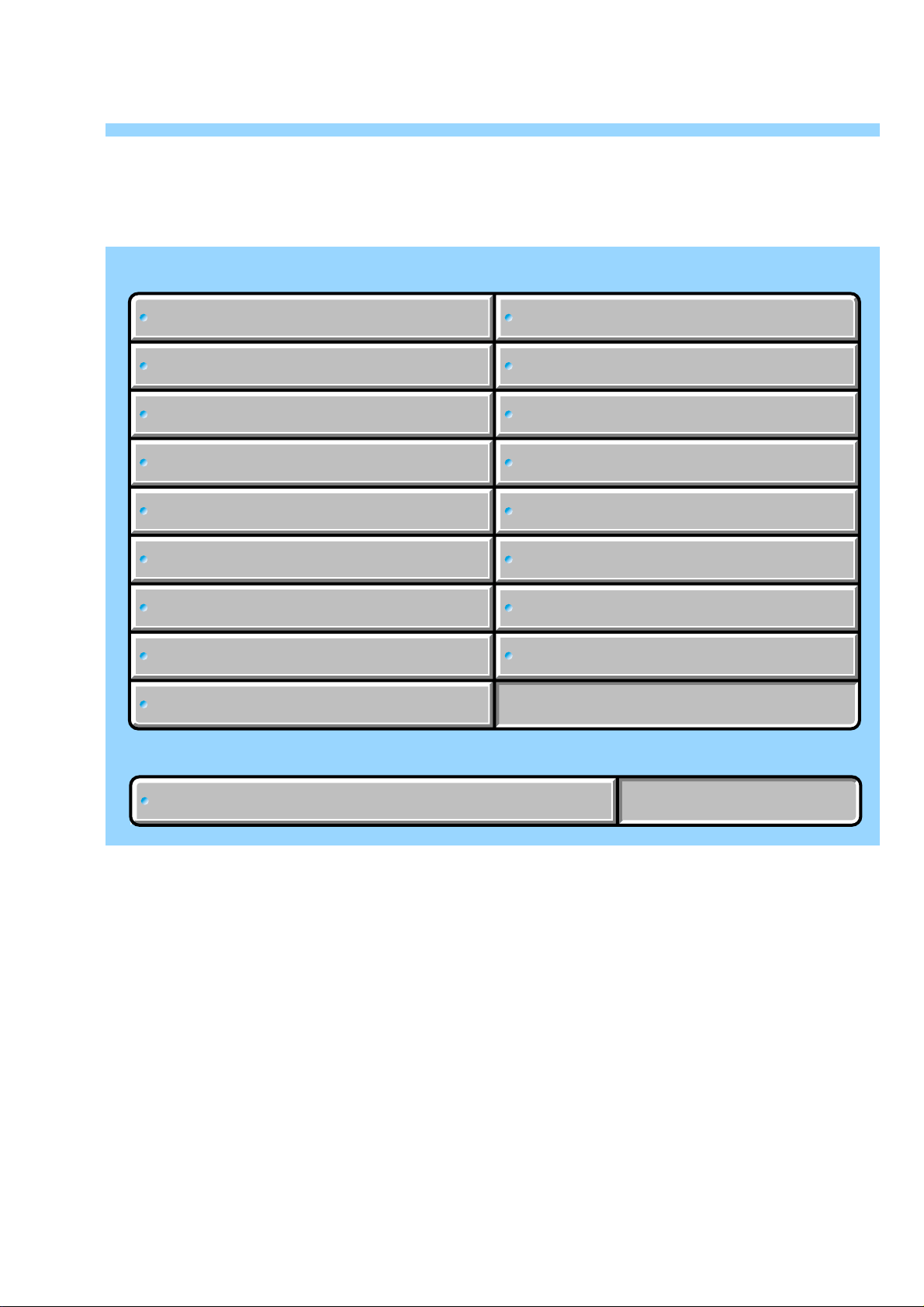
Table for differences of function
Model CCD-TRV128 CCD-TRV228 CCD-TRV228E CCD-TRV328 CCD-TRV428 CCD-TRV428E
Destination
US, CND, E,
AR, BR NE, E E, AUS, HK, JE
E
Remote commander ✕ aa✕ aa
Color system NTSC NTSC PAL NTSC NTSC PAL
Mechanism deck M2100 M2100 M2101 M2100 M2100 M2101
SteadyShot ✕✕✕aaa
LCD type Please refer to page 1-3 to discriminate the type of LCD (TYPE C or TYPE S).
AEP, UK, EE,
US, CND, E JE
AEP, EE, NE,
•Abbreviation
AR : Argentine model
AUS: Australian model
BR : Brazilian model
SAFETY-RELATED COMPONENT WARNING!!
COMPONENTS IDENTIFIED BY MARK 0 OR DOTTED LINE WITH
MARK 0 ON THE SCHEMATIC DIAGRAMS AND IN THE PARTS
LIST ARE CRITICAL TO SAFE OPERATION. REPLACE THESE
COMPONENTS WITH SONY PARTS WHOSE PART NUMBERS
APPEAR AS SHOWN IN THIS MANUAL OR IN SUPPLEMENTS
PUBLISHED BY SONY .
CND: Canadian model
EE : East European model
HK : Hong Kong model
JE : Tour ist model
NE : North European model
ATTENTION AU COMPOSANT AYANT RAPPORT
À LA SÉCURITÉ!
LES COMPOSANTS IDENTIFÉS P AR UNE MARQUE 0 SUR LES
DIAGRAMMES SCHÉMA TIQUES ET LA LISTE DES PIÈCES SONT
CRITIQUES POUR LA SÉCURITÉ DE FONCTIONNEMENT. NE
REMPLACER CES COMPOSANTS QUE PAR DES PIÈSES SONY
DONT LES NUMÉROS SONT DONNÉS DANS CE MANUEL OU
DANS LES SUPPÉMENTS PUBLIÉS PAR SONY.
SAFETY CHECK-OUT
After correcting the original service problem, perform the following
safety checks before releasing the set to the customer.
1. Check the area of your repair for unsoldered or poorly-soldered
connections. Check the entire board surface for solder splashes
and bridges.
2. Check the interboard wiring to ensure that no wires are
"pinched" or contact high-wattage resistors.
3. Look for unauthorized replacement parts, particularly
transistors, that were installed during a previous repair . Point
them out to the customer and recommend their replacement.
4. Look for parts which, through functioning, show obvious signs
of deterioration. Point them out to the customer and
recommend their replacement.
5. Check the B+ voltage to see it is at the values specified.
6. Flexible Circuit Board Repairing
•Keep the temperature of the soldering iron around 270˚C
during repairing.
• Do not touch the soldering iron on the same conductor of the
circuit board (within 3 times).
• Be careful not to apply force on the conductor when soldering
or unsoldering.
Unleaded solder
Boards requiring use of unleaded solder are printed with the leadfree mark (LF) indicating the solder contains no lead.
(Caution: Some printed circuit boards may not come printed with
the lead free mark due to their particular size.)
: LEAD FREE MARK
Unleaded solder has the following characteristics.
• Unleaded solder melts at a temperature about 40°C higher than
ordinary solder.
Ordinary soldering irons can be used but the iron tip has to be
applied to the solder joint for a slightly longer time.
Soldering irons using a temperature regulator should be set to
about 350°C.
Caution: The printed pattern (copper foil) may peel away if the
heated tip is applied for too long, so be careful!
• Strong viscosity
Unleaded solder is more viscous (sticky , less prone to flow) than
ordinary solder so use caution not to let solder bridges occur such
as on IC pins, etc.
• Usable with ordinary solder
It is best to use only unleaded solder but unleaded solder may
also be added to ordinary solder.
— 3 —
Page 4

CCD-TRV128/TRV228/TRV228E/TRV328/TRV428/TRV428E
TABLE OF CONTENTS
Section Title Page Section Title Page
1. SERVICE NOTE
1-1. Note for Repair ································································1-1
1-2. Power Supply During Repairs·········································1-1
1-3. To Take Out a Cassette when not Eject (Force Eject) ·····1-2
1-4. LCD Type Check ·····························································1-3
1-5. Self-diagnosis Function ···················································1-4
1-5-1.Self-diagnosis Function ···················································1-4
1-5-2.Self-diagnosis Display·····················································1-4
1-5-3.Service Mode Display ·····················································1-4
1-5-4.Self-diagnosis Code Table ···············································1-5
2. DISASSEMBLY
2-1. Flow Chart ·······································································2-1
2-2. Mechanism Deck Service Position··································2-3
2-3. LCD Service Position ······················································2-5
2-4. Circuit Boards Location ··················································2-6
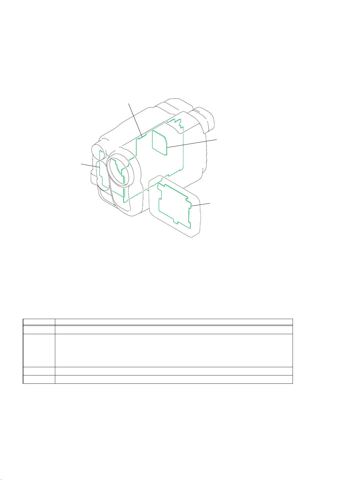
2-5. Flexible Boards Location ················································2-7
3. BLOCK DIAGRAMS
3-1. Overall Block Diagram (1/5)···········································3-1
3-2. Overall Block Diagram (2/5)···········································3-3
3-3. Overall Block Diagram (3/5)···········································3-5
3-4. Overall Block Diagram (4/5)···········································3-7
3-5. Overall Block Diagram (5/5)···········································3-9
3-6. Power Block Diagram (1/2)··········································· 3-11
3-7. Power Block Diagram (2/2)··········································· 3-13
5. REPAIR PARTS LIST
5-1. Exploded Views ····························································5-2
5-1-1. Ov erall Assembly·························································· 5-2
5-1-2. Front Panel Block ························································· 5-3
5-1-3. Lens Block ····································································5-4
5-1-4. LCD Block···································································· 5-5
5-1-5. Cabinet R Block····························································5-6
5-1-6. EVF Block ···································································· 5-7
5-1-7. Battery Panel Block ······················································5-8
5-1-8. MD Frame Block ··························································5-9
5-1-9. Cassette Compartment Assembly, Drum Assembly ···5-10
5-1-10. LS Chassis Block Assembly ·······································5-11
5-1-11. Mechanical Chassis Block Assembly-1 ······················5-12
5-1-12. Mechanical Chassis Block Assembly-2 ······················5-13
5-2. Electrical Parts List ·····················································5-14
4. PRINTED WIRING BOARDS AND
SCHEMATIC DIAGRAMS
4-1. Frame Schematic Diagram ··············································4-1
4-2. Schematic Diagrams························································4-5
CD-465 (CCD IMAGER)················································4-7
VC-341 (1/10)
(A/D CONVERTER, TIMING GENERATOR)··············4-9
VC-341 (2/10)
(CAMERA/VTR PROCESS, LENS CONTROL) ········4-11
VC-341 (3/10) (LENS DRIVE) ···································· 4-13
VC-341 (4/10) (REC/PB AMP) ····································4-15
VC-341 (5/10) (SERVO) ···············································4-17
VC-341 (6/10) (CAMERA/MECHA CONTROL) ······· 4-19
VC-341 (7/10) (HI CONTROL)····································4-21
VC-341 (8/10) (AUDIO, VIDEO)································· 4-23
VC-341 (9/10) (DC CONTROL) ··································4-25
VC-341 (10/10) (STEADYSHOT, CONNECTOR)······ 4-27
PD-204 (LCD DRIVER, BACKLIGHT DRIVE)·········4-29
SI-039 (STEADYSHOT, JACK) ···································4-31
FP-792 FLEXIBLE ·······················································4-31
FP-228, FP-299, FP-300, FP-301, FP-302, FP-802
FLEXIBLE ···································································· 4-33
SS-5100, PR-5100 (CONTROL KEY BLOCK)··········· 4-34
CF-5100 (CONTROL KEY BLOCK)···························4-35
4-3. Printed Wiring Boards ···················································4-39
CD-465 ·········································································· 4-41
VC-341 ·········································································· 4-43
PD-204···········································································4-47
SI-039, FP-792 FLEXIBLE ·········································· 4-49
FP-228, FP-299, FP-300, FP-301, FP-302, FP-802
FLEXIBLE ···································································· 4-51
4-4. Mounted Parts Location ················································4-53
— 4 —
Page 5
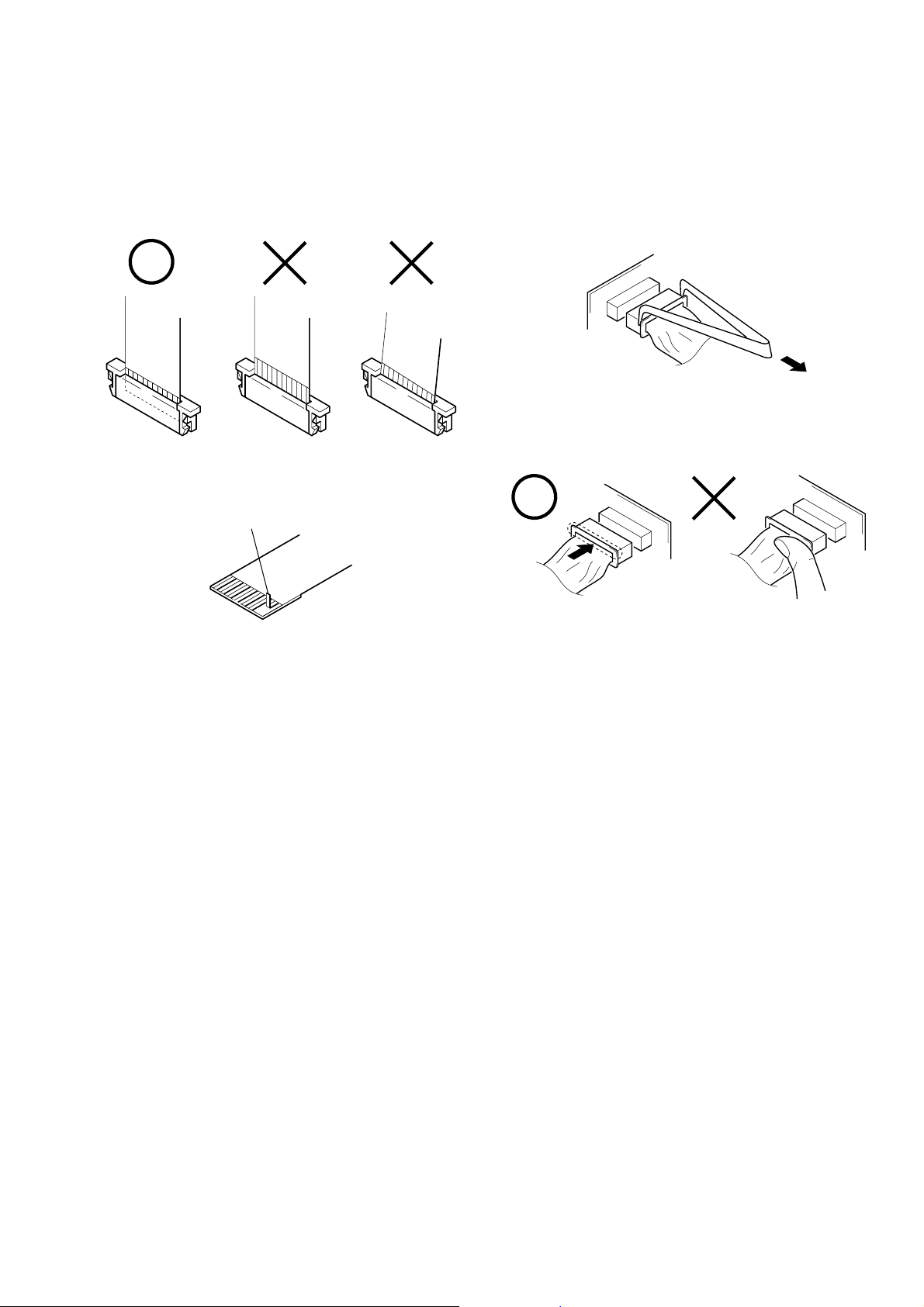
1-1. NOTE FOR REPAIR
When installing a connector, don’t press down at wire of connector.
It is possible that a wire is snapped.
CCD-TRV128/TRV228/TRV228E/TRV328/TRV428/TRV428E
SECTION 1
SERVICE NOTE
Make sure that the flat cable and flexible board are not cracked of
bent at the terminal.
Do not insert the cable insufficiently nor crookedly.
Cut and remove the part of gilt
which comes off at the point.
(Be careful or some
pieces of gilt may be left inside)
When remove a connector, don’t pull at wire of connector.
It is possible that a wire is snapped.
1-2. POWER SUPPLY DURING REPAIRS
In this unit, about 10 seconds after power is supplied to the battery terminal using the regulated po wer supply (8.4V), the power is shut of f so
that the unit cannot operate.
The following method is available to prevent this.
Method 1.
Use the AC power adaptor (AC-L10, AC-VQ800 etc.).
1-1
Page 6
CCD-TRV128/TRV228/TRV228E/TRV328/TRV428/TRV428E
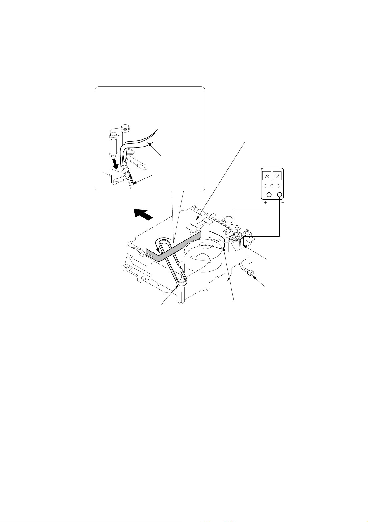
1-3. TO TAKE OUT A CASSETTE WHEN NOT EJECT (FORCE EJECT)
1 Refer to “SECTION 2. DISASSEMBLY” to remove the mechanism deck block.
2 Disconnect CN401 (2P) of VC-341 board.
3 Add +5V from the DC POWER SUPPLY and unload with a pressing the cassette compartment.
4 Pull the timing belt in the direction of
arrow A with a pincette while pressing
the cassette compartment (take care
not to damage) to adjust the bending
of a tape.
Press the cassette compartment not to
rise the cassette compartment
5 Let go your hold the cassette
compartment and rise the cassette
compartment to take out a cassette.
A
Timing belt
A
Timing belt
Pincette
[DC power supply]
(+5V)
Loading motor
Disconnect CN401
of VC-341 board.
Adjust the bending of a tape
1-2
Page 7
CCD-TRV128/TRV228/TRV228E/TRV328/TRV428/TRV428E
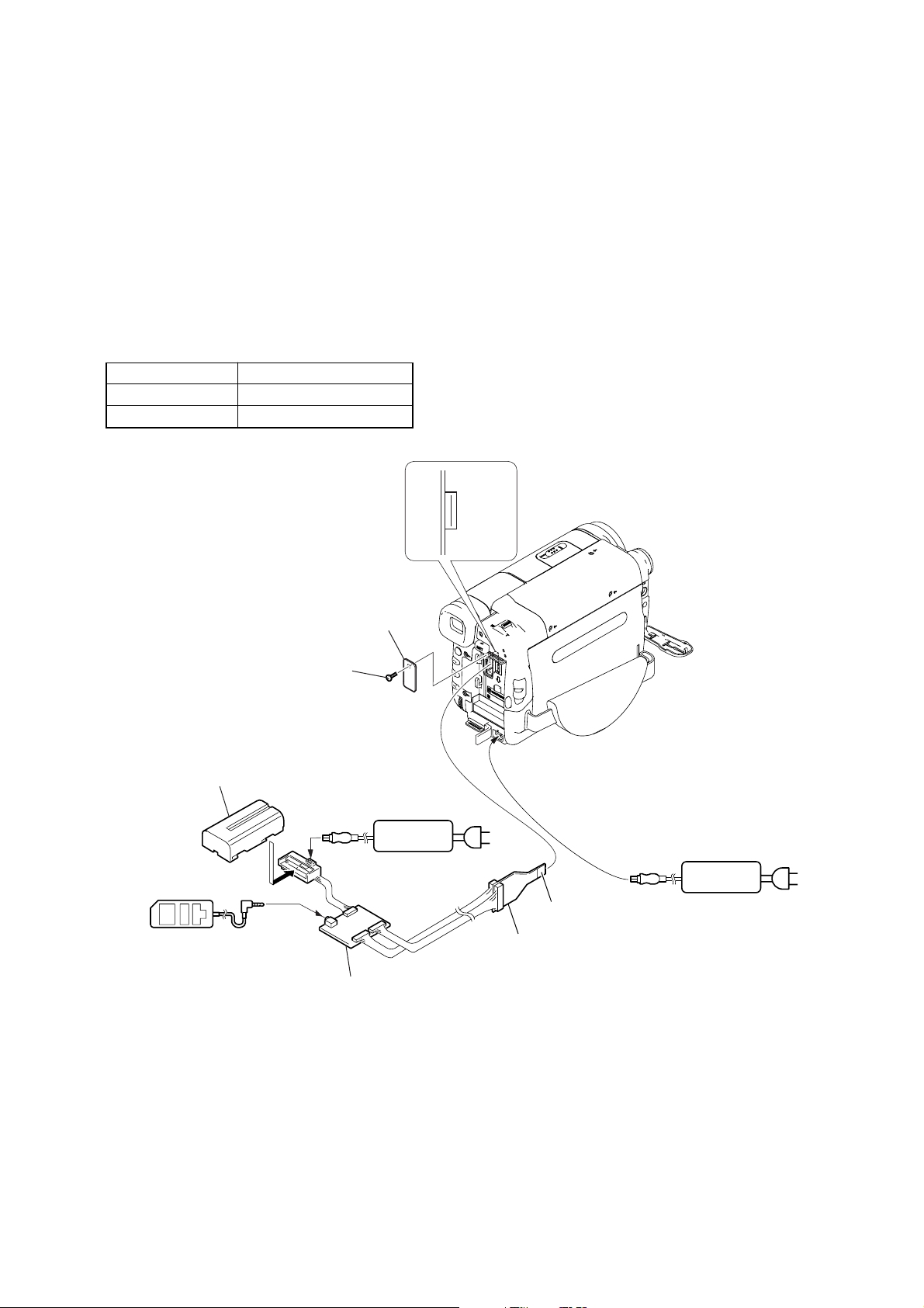
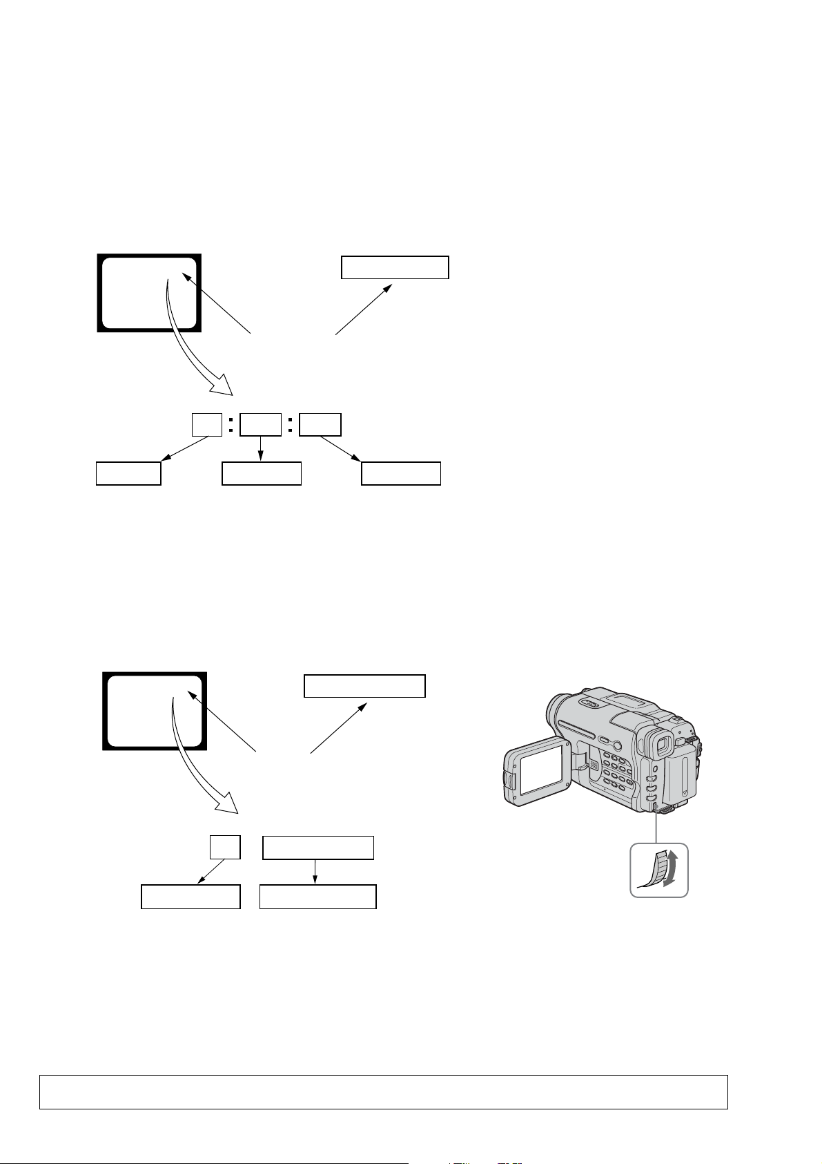
1-4. LCD TYPE CHECK
The LCD type can be checked with data value by connecting the adjustment remote commander.
Note: About PD-204 board and LCD module, discriminate LCD type on the machine, and replace the same type.
Preparations:
1) Connect the equipment for adjustments according to Fig. 1.
2) Connect the adjustment remote commander to VC-341 board CN007 via I/F unit for LANC control (J-6082-521-A) and CPC jig connector
(J-6082-539-A).
To operate the adjustment remote commander, connect the A C po wer adaptor to the DC IN jack of I/F unit for LANC control, or connect
the L series Info-LITHIUM battery to the battery terminal of I/F unit for LANC control.
Checking method:
1) Select page: 3, address: CC.
2) By checking the data value of display data, the type of LCD can be discriminated.
Data LCD type
64 to 67 TYPE C
40 to 43 TYPE S
CN007
1
Screw (M2)
L serices Info
LITHIUM battery (7.2Vdc)
LANC jack
Adjustment
remote commander (RM-95)
CPC lid
AC adaptor
16
AC IN
Conductor side
CPC jig connector
(J-6082-539-A)
AC adaptor
AC IN
I/F unit for LANC control
(J-6082-521-A)
1-3
Page 8
CCD-TRV128/TRV228/TRV228E/TRV328/TRV428/TRV428E
1-5. SELF-DIAGNOSIS FUNCTION
1-5-1. Self-diagnosis Function
When problems occur while the unit is operating, the self-diagnosis
function starts working, and displays on the viewfinder or Display
window what to do. This function consists of two display; selfdiagnosis display and service mode display.
Details of the self-diagnosis functions are provided in the Instruction
manual.
Viewfinder Display window
C : 3 1 : 1 1
Repaired by:
C : Corrected by customer
H : Corrected by dealer
E : Corrected by service
engineer
Blinks at 3.2Hz
C
Indicates the appropriate
step to be taken.
E.g.
31 ....Reload the tape.
32 ....Turn on power again.
3 1
Block
C : 3 1 : 11
1 1
Refer to “1-5-4. Self-diagnosis Code Table”.
1-5-2. Self-diagnosis Display
When problems occur while the unit is operating, the counter of the
viewfinder or Display window shows a 4-digit display consisting
of an alphabet and numbers, which blinks at 3.2 Hz. This 5-character
display indicates the “repaired by:”, “block” in which the problem
occurred, and “detailed code” of the problem.
Detailed Code
1-5-3. Service Mode Display
The service mode display shows up to six self-diagnosis codes shown in the past.
1. Display Method
While pressing the “STOP” key, set the switch from OFF to “ON”, and continue pressing the “STOP” key for 5 seconds continuously. The
service mode will be displayed, and the counter will show the backup No. and the 5-character self-diagnosis codes.
Viewfinder
[3] C : 3 1 : 1 1
[3]
Backup No.
Order of previous errors
Lights up
C : 3 1 : 1 1
Self-diagnosis Codes
Display window
3 C : 3 1 : 11
Control Dial
2. Switching of Backup No.
By rotating the control dial, past self-diagnosis codes will be shown in order. The backup No. in the [] indicates the order in which the
problem occurred. (If the number of problems which occurred is less than 6, only the number of problems which occurred will be shown.)
[1] : Occurred first time [3] : Occurred third time [5] : Occurred fifth time
[2] : Occurred second time [4] : Occurred fourth time [6] : Occurred the last time
3. End of Display
Turning OFF the power supply will end the service mode display.
Note: The “self-diagnosis display” data will not be erased (reset), when the lithium battery (CONTROL KEY BLOCK (CF-
5100): BT001) is removed.
1-4
Page 9

1-5-4. Self-diagnosis Code Table
Self-diagnosis Code
CCD-TRV128/TRV228/TRV228E/TRV328/TRV428/TRV428E
Repaired by:
C
C
C
C
C
C
C
C
C
C
C
C
C
C
C
C
C
C
C
C
C
C
C
C
C
C
C
C
C
Block
Function
04
21
22
31
31
31
31
31
31
31
31
31
31
31
31
31
32
32
32
32
32
32
32
32
32
32
32
32
32
Detailed
Code
00
00
00
10
11
20
21
22
23
30
31
40
41
42
43
44
10
11
20
21
22
23
30
31
40
41
42
43
44
Symptom/State
Non-standard battery is used.
Condensation.
Video head is dirty.
LOAD direction. Loading does not
complete within specified time
UNLOAD direction. Loading does not
complete within specified time
T reel side tape slacking when unloading
S reel
side tape slacking when unloading
T reel fault.
S reel fault.
FG fault when starting capstan.
FG fault during normal capstan operations.
FG fault when starting drum.
PG fault when starting drum.
FG fault during normal drum operations.
PG fault during normal drum operations.
Phase fault during normal drum operations.
LOAD direction loading motor time-
out.
UNLOAD direction loading motor
time-out.
T reel side tape slacking when
unloading.
S reel side tape slacking when
unloading.
T reel fault.
S reel fault.
FG fault when starting capstan.
FG fault during normal capstan
operations.
FG fault when starting drum.
PG fault when starting drum.
FG fault during normal drum
operations.
PG fault during normal drum
operations.
Phase fault during normal drum
operations.
Correction
Use the InfoLITHIUM battery.
Remove the cassette, and insert it again after one hour.
Clean with the optional cleaning cassette.
Load the tape again, and perform operations from the beginning.
Load the tape again, and perform operations from the beginning.
.
Load the tape again, and perform operations from the beginning.
.
Load the tape again, and perform operations from the beginning.
Load the tape again, and perform operations from the beginning.
Load the tape again, and perform operations from the beginning.
Load the tape again, and perform operations from the beginning.
Load the tape again, and perform operations from the beginning.
Load the tape again, and perform operations from the beginning.
Load the tape again, and perform operations from the beginning.
Load the tape again, and perform operations from the beginning.
Load the tape again, and perform operations from the beginning.
Load the tape again, and perform operations from the beginning.
Remove the battery or power cable, connect, and perform
operations from the beginning.
Remove the battery or power cable, connect, and perform
operations from the beginning.
Remove the battery or power cable, connect, and perform
operations from the beginning.
Remove the battery or power cable, connect, and perform
operations from the beginning.
Remove the battery or power cable, connect, and perform
operations from the beginning.
Remove the battery or power cable, connect, and perform
operations from the beginning.
Remove the battery or power cable, connect, and perform
operations from the beginning.
Remove the battery or power cable, connect, and perform
operations from the beginning.
Remove the battery or power cable, connect, and perform
operations from the beginning.
Remove the battery or power cable, connect, and perform
operations from the beginning.
Remove the battery or power cable, connect, and perform
operations from the beginning.
Remove the battery or power cable, connect, and perform
operations from the beginning.
Remove the battery or power cable, connect, and perform
operations from the beginning.
1-5
Page 10

CCD-TRV128/TRV228/TRV228E/TRV328/TRV428/TRV428E
Self-diagnosis Code
Block
Function
Repaired by:
E
61
E
61
E
62
E
62
*1: STEADYSHOT model (CCD-TRV328/TRV428/TRV428E)
Detailed
Code
00
10
00
01
Symptom/State
Difficult to adjust focus
(Cannot initialize focus.)
Zoom operations fault
(Cannot initialize zoom lens.)
Steadyshot function does not work well.
(With pitch angular velocity sensor output
stopped.)
Steadyshot function does not work well.
(With yaw angular velocity sensor output
stopped.)
Correction
Inspect the lens block focus reset sensor (Pin qs of CN201 of VC-
341 board) when focusing is performed when the control dial is
rotated in the focus manual mode and the focus motor drive circuit
(IC201 of VC-341 board) when the focusing is not performed.
Inspect the lens block zoom reset sensor (Pin qg of CN201 of VC341 board) when zooming is performed when the zoom switch is
operated and the zoom motor drive circuit (IC201 of VC-341 board)
when zooming is not performed.
Inspect pitch angular velocity sensor (SE752 of SI-039 board)
peripheral circuits. *1
Inspect yaw angular velocity sensor (SE751 of SI-039 board)
peripheral circuits. *1
1-6E
Page 11
CCD-TRV128/TRV228/TRV228E/TRV328/TRV428/TRV428E
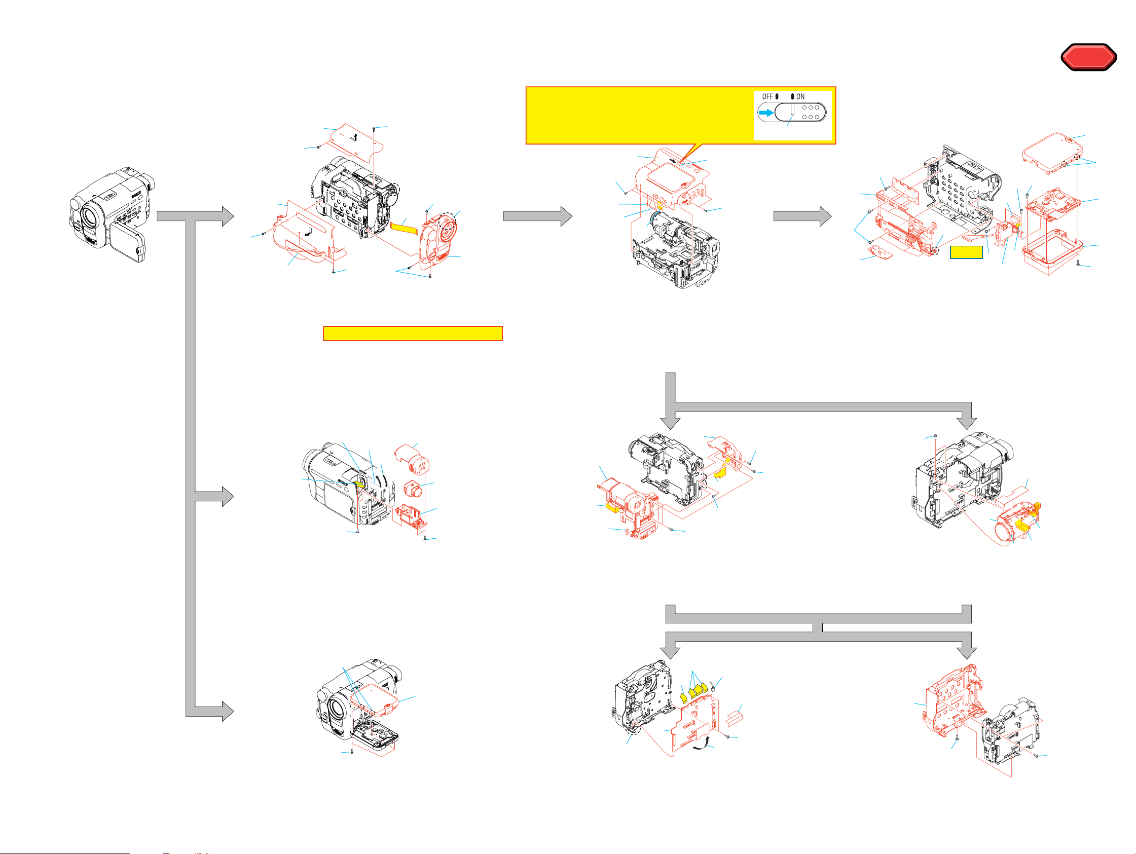
SECTION 2
DISASSEMBLY
2-1. FLOW CHART
The following flow chart shows the disassembly procedure.
1
5
4
3
1 Lock ace
2 Cabi (upper)
3 Grip belt
4 Lock ace
5 Cabi (L)
x3
x3
2
4
6 Lock ace
1
6
9
6
x3
7 Claw
8 Front panel
Note: Flexible board is connected.
9 FP-795: CN755, CN009
7
8
Note: When you remove Cabinet (R) Block,
or when you assembly, please slide
NS knob to the position of "ON".
3
1
6
5
4
1 Lock ace
x6
2
1
2 NS knob to the position of "ON".
3 Cabi (R)
4 VC-341: CN005
5 VC-341: CN002
6 VC-341: CN008
NS knob
3
2
5
1
1 Tripod Screw
2 Tapping P2
3 Tapping P2
4 Claw
5 CF-5100
6 Tapping P2
7 Claw
8 P Cabi (C)
x2
4
q;
9
qd
HELP
9 Tapping P2
x2
q; Tapping P2
x6
qa P Cabi (M)
qg
qs
qh
x2
x1
qs PD-204: CN6005
qd PD-204: CN6001
qf PD-204, LCD901, ND901
x4
qg Tapping P2
x4
qh Hinge assy
HELP
HELP
8
7
qf
qa
6
4
7
2
1 Lift up the EVF.
2 Tapping P2
x4
3 Down the EVF.
4 EVF block
2
1
3
5
8
6
2
5 EVF Cabi (upper)
6 EVF Cabi (lower)
7 FP-797: LCD902
8 EVF lens
3
4
1
2
1 VC-341: CN004
2 VC-341: CN053
3 Lock ace
x3
4 EVF/Battely panel block
7
8
5
6
3
7
5 VC-341: CN006
6 Tapping P2
7 Lock ace
8 SS-5100
2
3
1
3
x1
x1
4
6
1 VC-341: CN151
2 VC-341: CN201
3 Lens sheet
2
3
1
2
5
4 Lock ace
x2
5 Boss
6 Lens LSV-820A
1
1 Tapping P2
2 Claw
x2
3 P Cabi (C)
2-1 2-2
x4
8
5
1 VF blind sheet
2 VC-341: CN402, CN403, CN481
3 VC-341: CN401
4 Screw (M1.7)
x2
4
6
5 Claw
6 Open the VC-341.
7 VC-341: CN404
8 VC-341
1
1 Screw (M1.7)
2 CS frame
1
x3
Page 12
CCD-TRV128/TRV228/TRV228E/TRV328/TRV428/TRV428E
2-2. MECHANISM DECK SERVICE POSITION
Connection to Check the Mechanism deck
To check the mechanism deck, set the Camera or VTR to the "Forced power ON" mode. (Or, connect the control key
block (SS-5100) to the CN006 of VC-341 board and set the power switch to the "CAMERA" or "PLAY/edit" position.)
Operate the Camera functions of the zoom and focus, the VTR function using the adjustment remote commander
(with the HOLD switch set in the OFF position).
4
5
3
1
2
4
6
1
9
6
7
8
2
1
1
Setting the "Forced Camera Power ON" mode
1) Select page: 0, address: 01, and set data: 01.
2) Select page: D, address: 10, set data: 02 and
press the PAUSE button of the adjustment remote
commander.
Setting the "Forced VTR Power ON" mode
1) Select page: 0, address: 01, and set data: 01.
2) Select page: D, address: 10, set data: 02 and
press the PAUSE button of the adjustment remote
commander.
How to move up the cassette
compartment manually
Press the cassette compartment
in the direction of the arrow A
to move it up in the direction of
the arrow B.
Lens block
A
B
Exiting the "Forced Power ON" mode
1) Select page: 0, address: 01, and set data: 01.
2) Select page: D, address: 10, data: 00, and press the PAUSE
button of the adjustment remote commander.
3) Select page: 0, address: 01, and set data: 00.
Mechanism deck
1
4
2
1
6
5
3
4
3
8
2
5
6
1
7
3
4
5
8
7
6
2
5
6
3
3
2
1
1
4
Front panel block
Cabinet R block
EVF block/
Battery panel block assembly
AC IN
AC adaptor
VC-341 board
Info lithium battery
(L series)
CPC jig connector
(J-6082-539-A)
Contacting
surface
Adjustment remote
commander (RM-95)
I/F unit for LANC control
(J-6082-521-A)
Eject switch
Control key block
(SS-5100)
When exiting the "Forced Power ON" mode, connect the control
key block (SS-5100) to the CN006 of VC-341 board. Or, when
ejecting the cassette, connect the control key block (SS-5100) to
the CN006 of VC-341 board. and press the Eject switch.
2-3 2-4
Page 13
2-3. LCD SERVICE POSITION
AC adaptor
AC IN
AC adaptor
I/F unit for LANC control
(J-6082-521-A)
CPC jig connector
(J-6082-539-A)
CPC jig connector
L serices Info
LITHIUM battery (7.2Vdc)
LCD panel
PD-204 board
Back light unit
Adjustment
remote commander (RM-95)
Conductor side
CN007
1
16
LANC jack
AC IN
2
1
3
CCD-TRV128/TRV228/TRV228E/TRV328/TRV428/TRV428E
2-5
Page 14
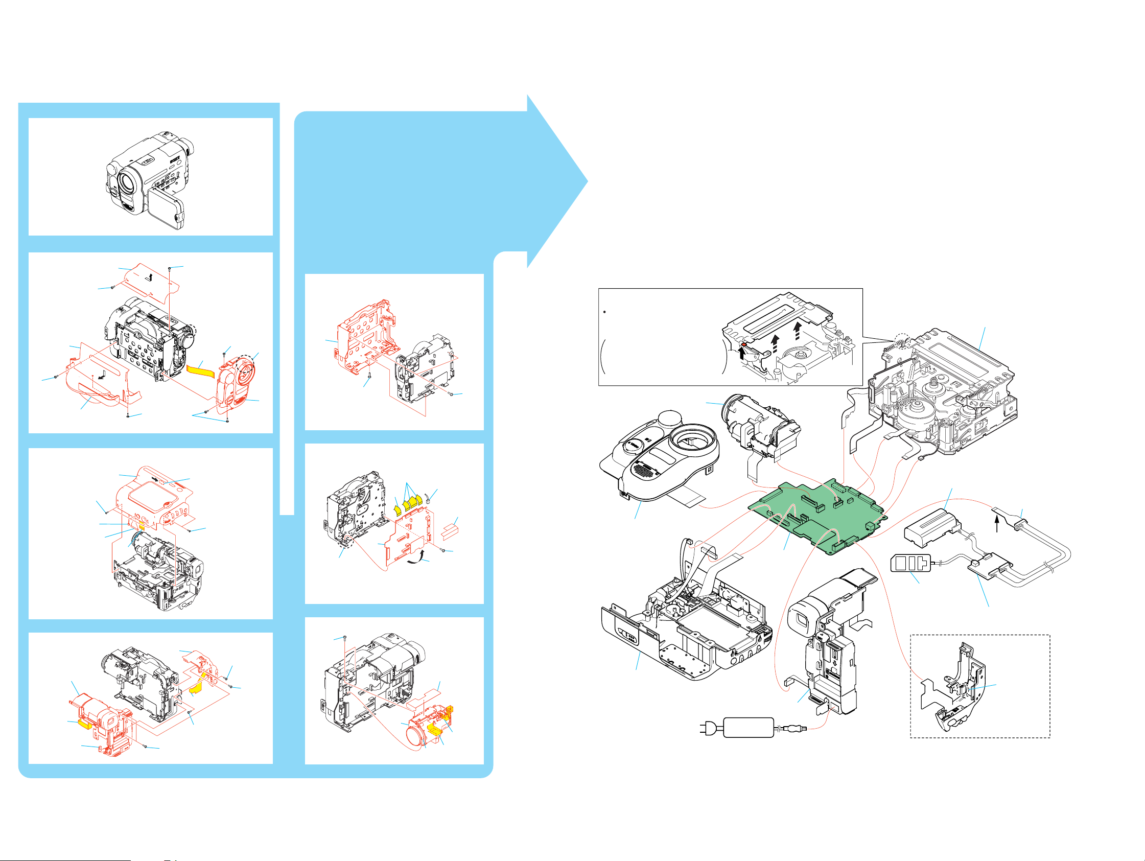
CCD-TRV128/TRV228/TRV228E/TRV328/TRV428/TRV428E
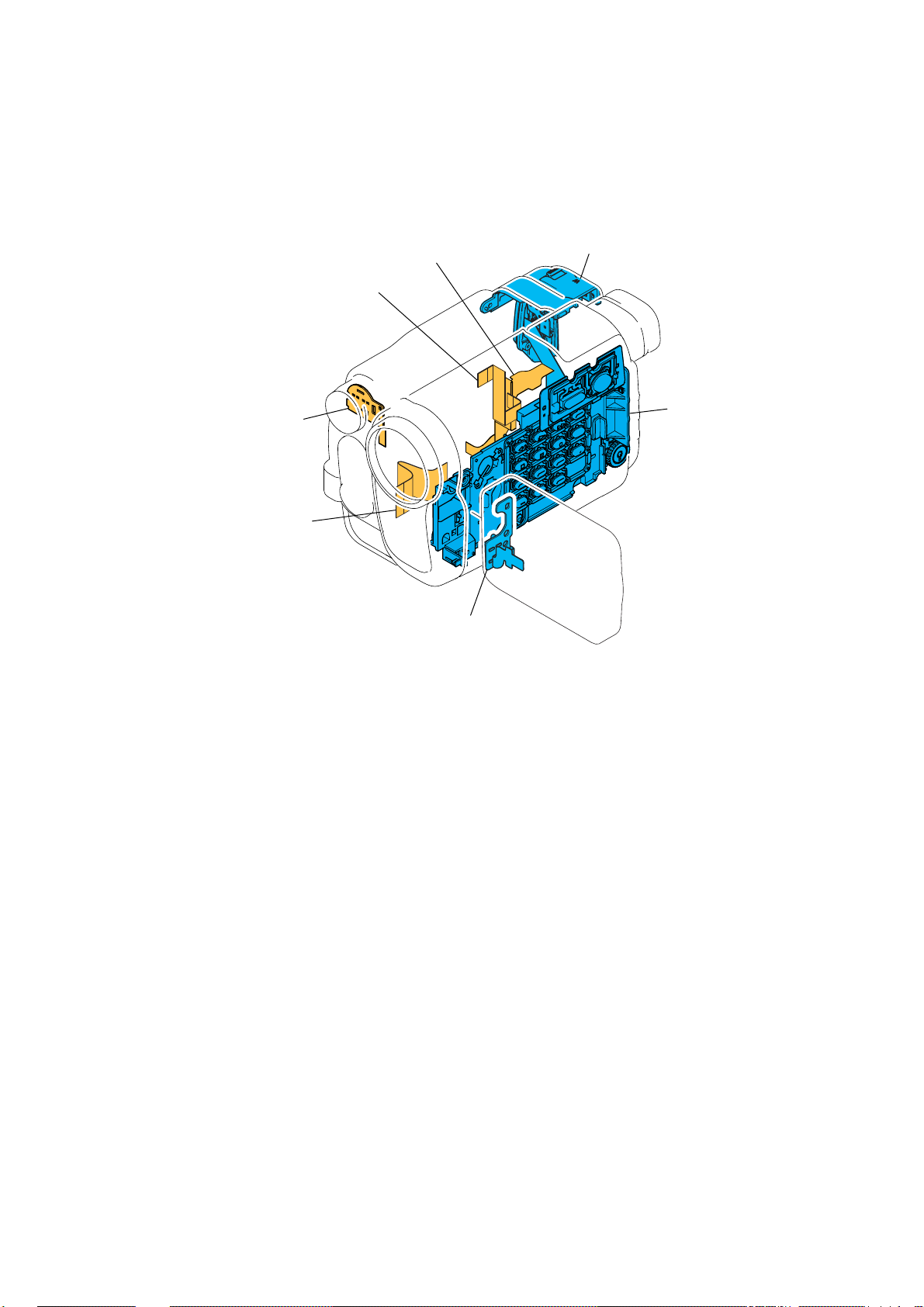
2-4. CIRCUIT BOARDS LOCATION
VC-341
SI-039
CD-465
PD-204
Board Name Function
CD-465 CCD IMAGER
VC-341 A/D CONVERTER, TIMING GENERATOR, CAMERA/VTR PROCESS,
LENS CONTROL, LENS DRIVE, REC/PB AMP, SERVO,
CAMERA/MECHA CONTROL, HI CONTROL, AUDIO, VIDEO, DC CONTROL,
STEADYSHOT, CONNECTOR
PD-204 LCD DRIVE, BACKLIGHT DRIVE
SI-039 STEADYSHOT, JACK
2-6
Page 15
CCD-TRV128/TRV228/TRV228E/TRV328/TRV428/TRV428E
2-5. FLEXIBLE BOARDS LOCATION
FP-792
FP-795
FFC-005
FP-797
PR-5100
SS-5100
CF-5100
2-7E
Page 16
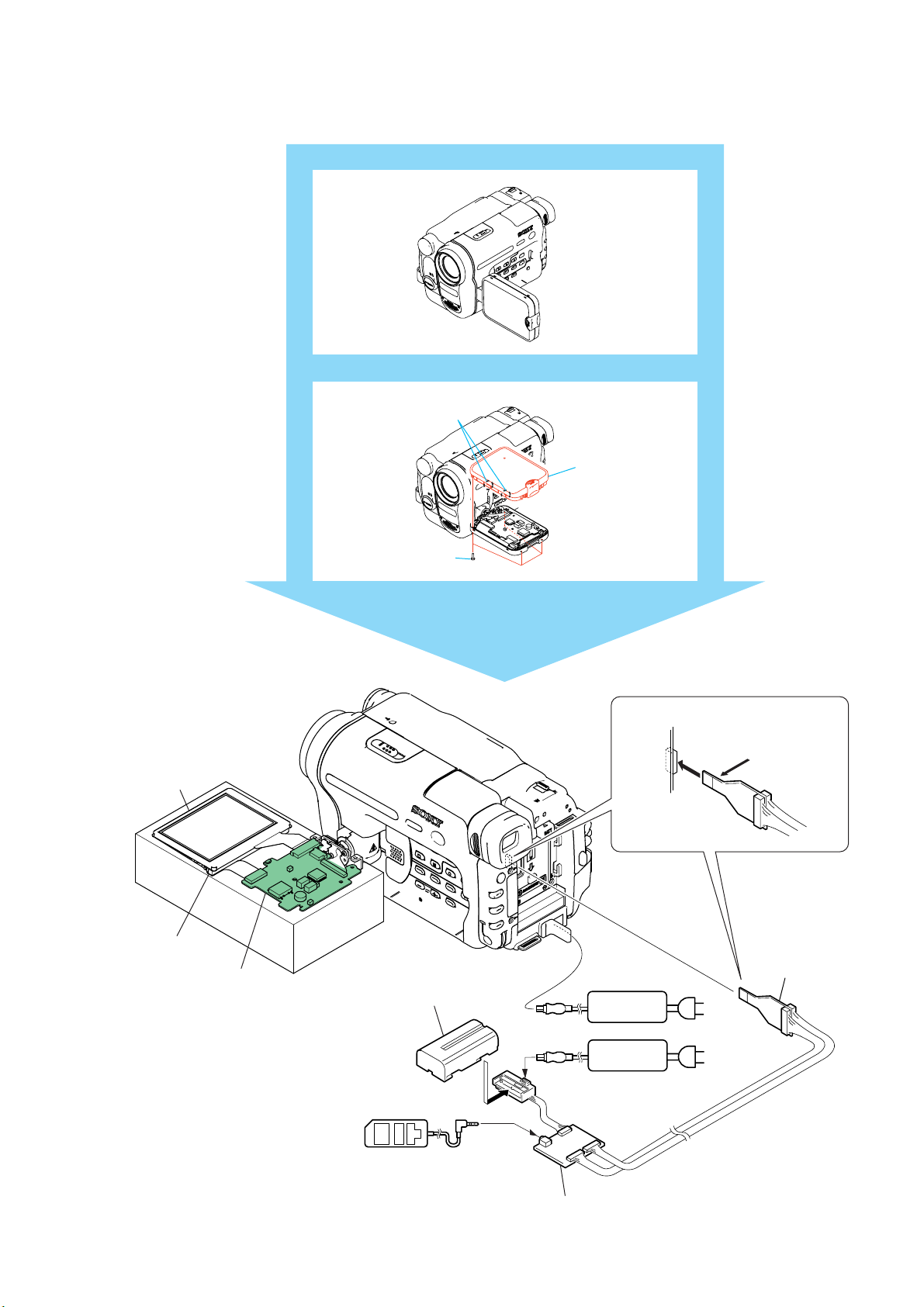
CCD-TRV128/TRV228/TRV228E/TRV328/TRV428/TRV428E
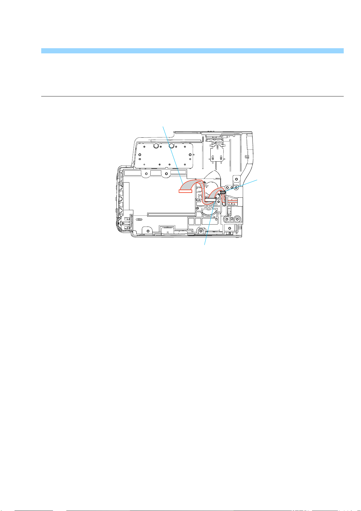
HELP
Sheet attachment positions and procedures of processing the flexible boards/harnesses are shown.
Harness (PD-124)
Claw
Claw
Note: Close the LCD panel, when you work.
HELP
Page 17
Link
Link
CCD-TRV128/TRV228/TRV228E/TRV328/TRV428/TRV428E
3. BLOCK DIAGRAMS
OVERALL BLOCK DIAGRAM (1/5)
OVERALL BLOCK DIAGRAM (1/5)
OVERALL BLOCK DIAGRAM (2/5)
OVERALL BLOCK DIAGRAM (2/5)
OVERALL BLOCK DIAGRAM (3/5)
OVERALL BLOCK DIAGRAM (3/5)
OVERALL BLOCK DIAGRAM (4/5)
OVERALL BLOCK DIAGRAM (4/5)
OVERALL BLOCK DIAGRAM (5/5)
OVERALL BLOCK DIAGRAM (5/5)
POWER BLOCK DIAGRAM (1/2)
POWER BLOCK DIAGRAM (1/2)
POWER BLOCK DIAGRAM (2/2)
POWER BLOCK DIAGRAM (2/2)
Page 18
CCD-TRV128/TRV228/TRV228E/TRV328/TRV428/TRV428E
SECTION 3
BLOCK DIAGRAMS
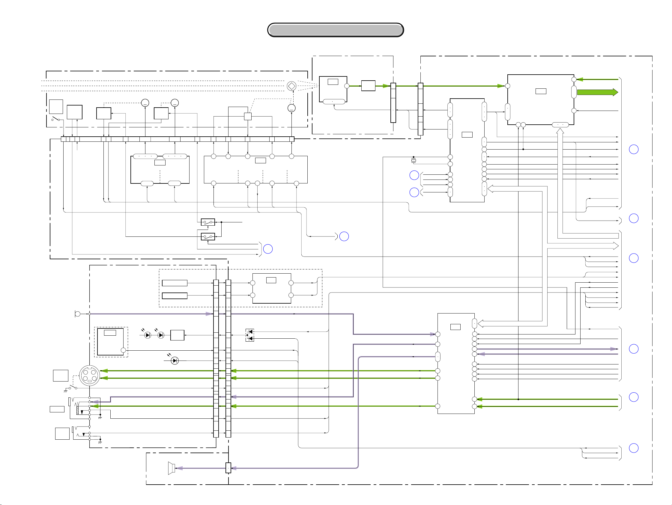
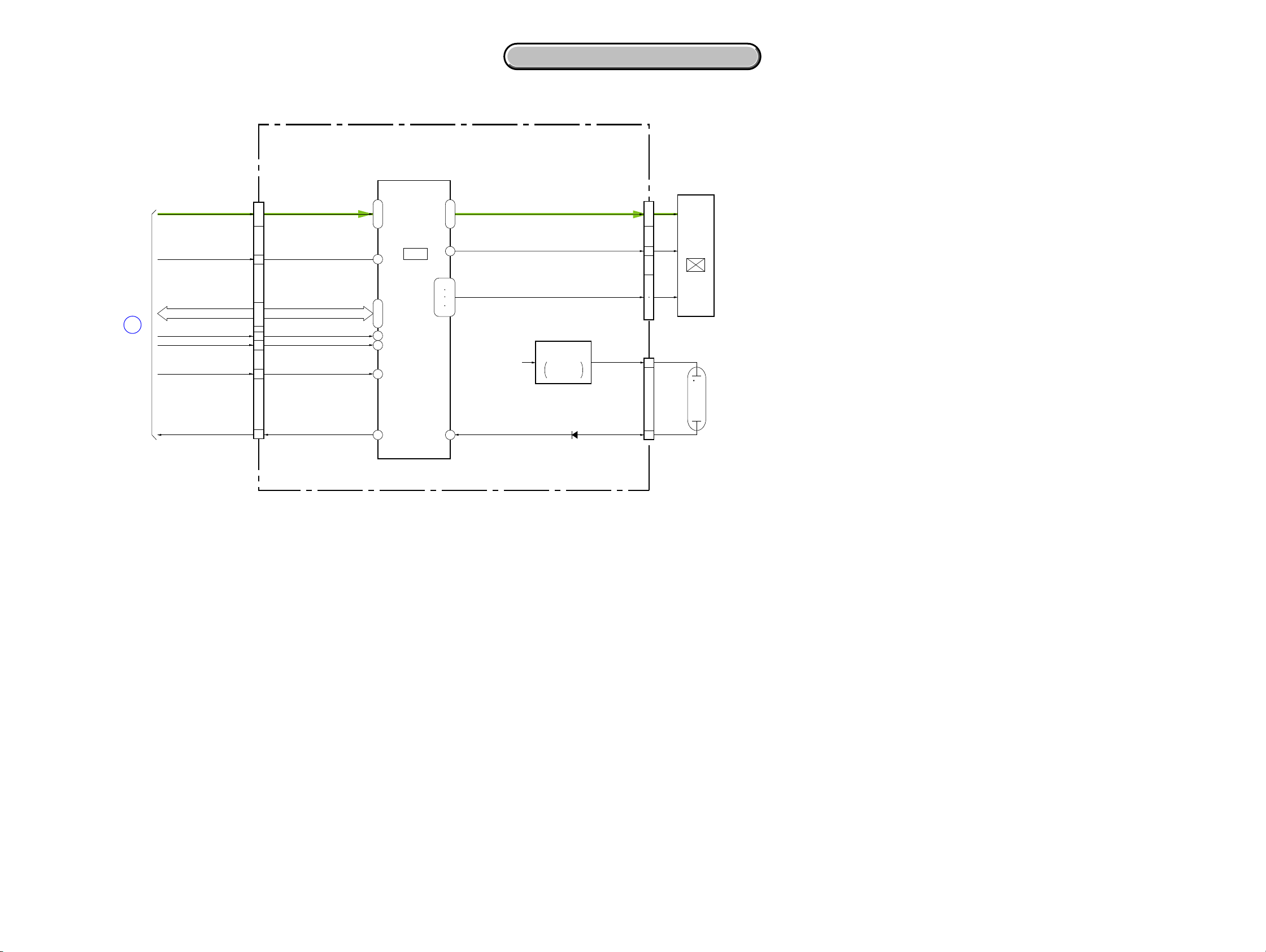
3-1. O VERALL BLOCK DIAGRAM (1/5)
LENS BLOCK
ZOOM MOTOR
NIGHT
SHOT
PLUS
CN201
LENS
TEMP
SENSOR
5 15 12 21 19
17 18
TEMP
IR SWITCHXNS SW
D 2.8V
ZOOM
SENSOR
FC SENSE OUT
ZM SENSE OUT
ZM RST
FC RST
ZM SENSE VCC
MM MM
10 – 7
5717 19 24
ZOOM
MOTOR
DRIVE
13 – 16
FOCUS
SENSOR
ZOOM
A,B,XA,XB
IC201
(3/10)
EN1
DIR1A
DIR1B
FOCUS MOTOR
1 – 4
FOCUS
MOTOR
DRIVE
9 – 12
3. BLOCK DIAGRAMS
3. BLOCK DIAGRAMS
( ) : Number in parenthesis ( ) indicates the division number of schematic diagram where the component is located.
CD-465 BOARD VC-341 BOARD (1/4)
CN951 CN151
Q951
BUFFER
V1-V4,RG,H1,H2
28.636363MHz : TRV128/TRV228/TRV328/TRV428
1
7
ı
9
11
ı
14
28.375MHz : TRV228E/TRV428E
OVERALL (3/5)
(PAGE 3-5)
OVERALL (3/5)
(PAGE 3-5)
X151
2
17
14
6
ı
8
1
ı
4
CCD OUT
RG, H1, H2
V1 – V4
XCS IC 301
XRST VTR
CAM DD ON
CK CONT 1, 2
FOCUS
A,B,XA,XB
21 23
EN0
DIR0A
DIR0B
1316
FC SENSE VCC
IRIS
BIAS(+)
1
HALL
BIAS
HALL
REF
2322
IRIS
HALL(+)
2
HALL
OFFSET
H
5
HALL
AMP
6
IRIS
HALL(-)
(3/10)
IC202
73
HALL
IRIS
IRIS
METER
IC951
CCD
IMAGER
1 – 4 12 – 14
7
MM
20
IRIS
BIAS(-)
14
HALL
GAIN
12
HALL
AD
GAIN
IRIS DRIVE(-)
8
IRIS
DRIVE
10
IRIS PWM
22
21
18
25
26
28
31
4
5
39
40
42
47
46
IC151
TIMING
GENERATOR
(1/10)
CLPDM,
PBLK,
1
XSHP,
2
XSHD
15
16
11
12
9
44
45
34
41
48
36
35
38
37
30
19
21
ı
23
34
16
VC SO, VC SI, XVC SCK
IC152
S/H, AGC,
A/D CONVERTER
(1/10)
46 4847
36
2
11
20
ı
PB C RF
AD1-AD10
CLP1
PBLK
MCK, CL
ADCK
AHD, AVD
XSG1
XV1
V STOP
EN0, DIR0A,B,
EN1, DIR1A,B,
FC RST, ZM RST
ID
1
OVERALL (2/5)
(PAGE 3-3)
MIC901
MICROPHONE
J751
S VIDEO
OUT
J752
A/V OUT
J753
RFU DC
OUT
SI-039 BOARD (1/2)
LND755
TRV228/TRV228E/
TRV428/TRV428E
IC751
REMOTE
COMMANDER
RECEIVER
1
S Y I/O
S C I/O
XS JACK IN
CN755 (1/2)
SIRCS PWM/
IR DRV EN
XSIRCS SIG
XF TALLY LED
AUDIO L I/O
VIDEO I/O
AV JACK IN
DCOUT JACK IN DCOUT JACK IN
D753, 754
(IR EMITTER)
D759
(TALLY)
SE752
PITCH SENSOR
SE751
YAW SENSOR
Q751
LED
DRIVE
CONTROL KEY BLOCK (CF-5100) (1/2)
SP901
SPEAKER
05
Q202 (1/2)
LIA 1
LIA 2
Q202 (2/2)
26
24
27
15
18
20 11
9
5
7
13
11
14
ZM RST LED
LENS TEMP AD
CN009 (1/2)
5
7
4
16
13
22
26
24
18
20
17
301
CN008
1
2
D 2.8V
FC RST LED
D001
SP (+), (–)
IRIS PWM
XNS SW
HALL AD,
PITCH AD
YAW AD
XCS AU
BEEP
AV JACK IN
XS JACK IN
IR ON
FRQ TUNE
RF SWP
REC AFM
PB RF
A FADE
1.5M DEV
AU BPF
FSC
IC 301 Y OUT
IC 301 C OUT
SIRCS PWM
SIRCS SIG
XF TALLY LED
CL
HALL OFFSET,
HALL GAIN,
HALL REF
OVERALL (3/5)
4
(PAGE 3-5)
TRV328/TRV428/TRV428E
IC271
8
STEADY
SHOT
(10/10)
12
SIRCS PWM
XF TALLY LED
INT MIC
SIRCS SIG
2
18
PITCH AD
YAW A D
IR_ON
XS JACK IN
AV JACK IN
OVERALL (2/5)
3
(PAGE 3-4)
INT MIC
AUDIO L I/O
SP+,–
S Y I/O
S C I/O
VIDEO I/O
58
56
49
51
21
17
19
IC801
AUDIO/VIDEO
PROCESS
(8/10)
24
25
26
27
46
33
31
9
10
11
28
13
15
CS CH, CH SO, CH SCK
VC SO, VC SI, XVC SCK
DCOUT JACK IN
VC SO, XVC SCK
16
OVERALL (3/5)
(PAGE 3-6)
5
OVERALL (3/5)
(PAGE 3-5)
6
OVERALL (2/5)
(PAGE 3-4)
7
OVERALL (2/5)
(PAGE 3-3)
8
OVERALL (4/5)
(PAGE 3-8)
A : VIDEO SIGNAL
A : AUDIO SIGNAL
3-1 3-2
Page 19
CCD-TRV128/TRV228/TRV228E/TRV328/TRV428/TRV428E
3. BLOCK DIAGRAMS
3. BLOCK DIAGRAMS
3-2. OVERALL BLOCK DIAGRAM (2/5)
VC-341 BOARD (2/4)
PB C RF
187
ı
196
183
172
81
164
185
198
169
170
166
168
171
167
148
ı
153
161
162
4
213
67
53
58
83
84
86
87
89
93
94
88
85
101
100
157
158
IC301
CAMERA/VTR
PROCESS, ATF,
LENS CONTROL
(2/10)
OVERALL (1/5)
(PAGE 3-2)
OVERALL (1/5)
(PAGE 3-2)
OVERALL (3/5)
(PAGE 3-5)
OVERALL (3/5)
(PAGE 3-5)
1
7
9
10
AD1 – AD10
CLP1
PBLK
MCK, CL
ADCK
AHD, AVD
XSG1
XV1
ID
V STOP
EN0, DIR0A, B,
EN1, DIR1A, B
FC RST, ZM RST
IC 301 Y OUT
IC 301 C OUT
AFC F0
LCD HOLD
JOG VD
X1/2 SWP
XSG V RST
ATF SAMPLE
MECHA FLD, MECHA HD,
MECHA VD
SYS V
SWP DIR
CK CONT1, 2
XTBC V RST
TBC VD
Q306
BUFFER
Q304
VCO
( ) : Number in parenthesis ( ) indicates the division number of schematic diagram where the component is located.
7
51
49
77
98
99
66
95
ı
97
79
146
144
179
180
ı
182
174
ı
177
14
17
24
75
74
76
DOP
AFC F0 ADJ
FSC
PANEL R
PANEL G
PANEL B
PANEL HD
PANEL VD
PANEL SYNC
REC RF
RF AGC OUT
PB C RF
XCS IC 301
XRST VTR
VC SO, VC SI, XVC SCK
VI HD
24 4
VI VDO
23
CGCK
OSD P ON,
OSD R ON,
OSD L ON
COLOR 1
COLOR 4
8
19
17
15
ı
22
ı
20
18
Q302
BUFFER
OVERALL (3/5)
11
IC302
CHARACTER
GENERATOR
(2/10)
PANEL R
PANEL G
PANEL B
(PAGE 3-5)
1
ı
3
XRST VTR
OVERALL (1/5)
(PAGE 3-1)
XCS OSD, OSD SO, XOSD SCK
3
XRF AGC OFF
RF AGC CONT
AFC F0 ADJ
HALL OFFSET,
HALL GAIN,
HALL REF
VC SO, XVC SCK
FSC
VI VDO
OVERALL (3/5)
(PAGE 3-5)
6
25
25
23
17
ı
19
27
28
AGC SLOW
BOTH REC
12
(D/A CONVERTER)
RP PB MODE
DOP
DA STRB
IC251
EVR
(4/10)
15
3
4
5
26
24
21
20
7
12
9
10
22
16
Q484, 485
SWITCH
REC Y/MT CONT
REC L CONT
MT FO
DOC DET
RP IR
REC BIAS
MT Q
XMP/ME
A FADE
1.5M DEV
AU BPF
FRQ TUNE
RF SWP
6
9
11
REC/PB AMP
10
46
13
7
3
48
15
12
8
32
19
14 1 47
IC481
(4/10)
27
28
34
33
Q481 – 483
ERASE
HEAD
OSC
38
39
XCS OSD, OSD SO, XOSD SCK
SP1X
SP2X
RF SWP
REC AFM
1.5M DEV
FRQ TUNE
RF SWP
CN481
FE (X)
PB RF
A FADE
AU BPF
FCS
XFE ON
VIVDO
VIDEO HEAD
CH
SP1
FLYING
CH
SP2
7
9
2
(FOR CHECK)
3
ERASE
CPC
EVF BLOCK
5
7
11
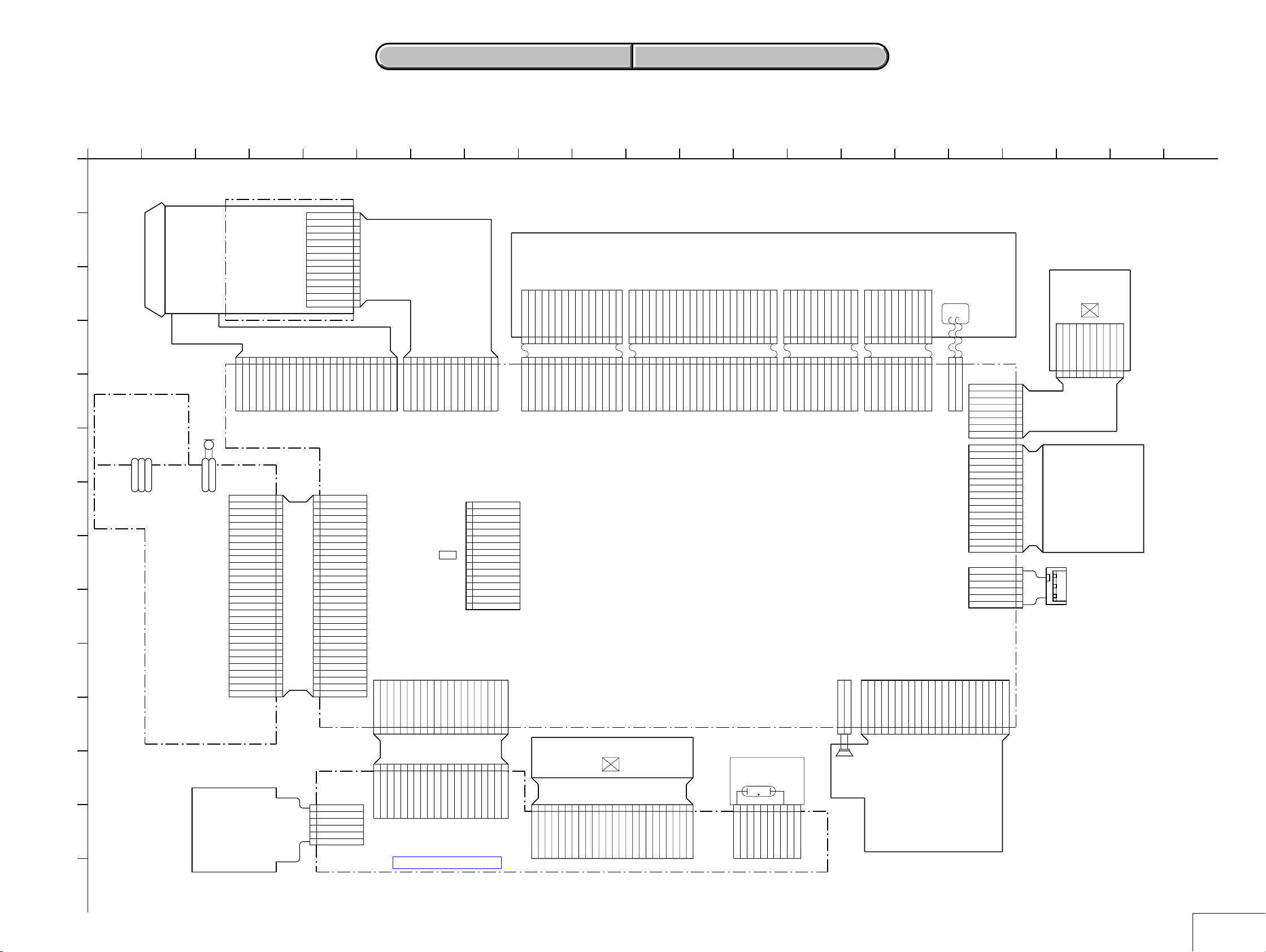
M2100/M2101
MECHA DECK (1/2)
M2100: TRV128/TRV228/TRV328/TRV428
M2101: TRV228E/TRV428E
CN007
(1/3)
REC RF
PB RF
BPF MONI
OVERALL (1/5)
6
(PAGE 3-2)
OVERALL (3/5)
15
(PAGE 3-5)
OVERALL (5/5)
(PAGE 3-9)
18
CN002 (1/2)
PANEL HOLD
14
7
PANEL R, PANEL G, PANEL B
ı
5
C-SYNC/XHD
9
PANEL XVD
8
11
ı
VC SO, VC SI, XVC SCK
13
XCS LCD DA
10
BL CONT
4
05
EVF G/BW Y
34
PANEL SYNC
PANEL VD
EVF DD ON
VC SO, VC SI, XVC SCK
XCS LCD
BL CONT
13
14
OVERALL (3/5)
(PAGE 3-5)
OVERALL (4/5)
(PAGE 3-8)
A : VIDEO SIGNAL
A : AUDIO SIGNAL
A : VIDEO/SERVO SIGNAL
A : VIDEO/AUDIO/SERVO SIGNAL
3-3 3-4
PANEL VD
PANEL HD
VIDEO IN
VSYNC
HSYNC
NSLEEP
CN004
LCD902
6
5
4
2
B/W
LCD UNIT
Page 20
3. BLOCK DIAGRAMS
3. BLOCK DIAGRAMS
CCD-TRV128/TRV228/TRV228E/TRV328/TRV428/TRV428E
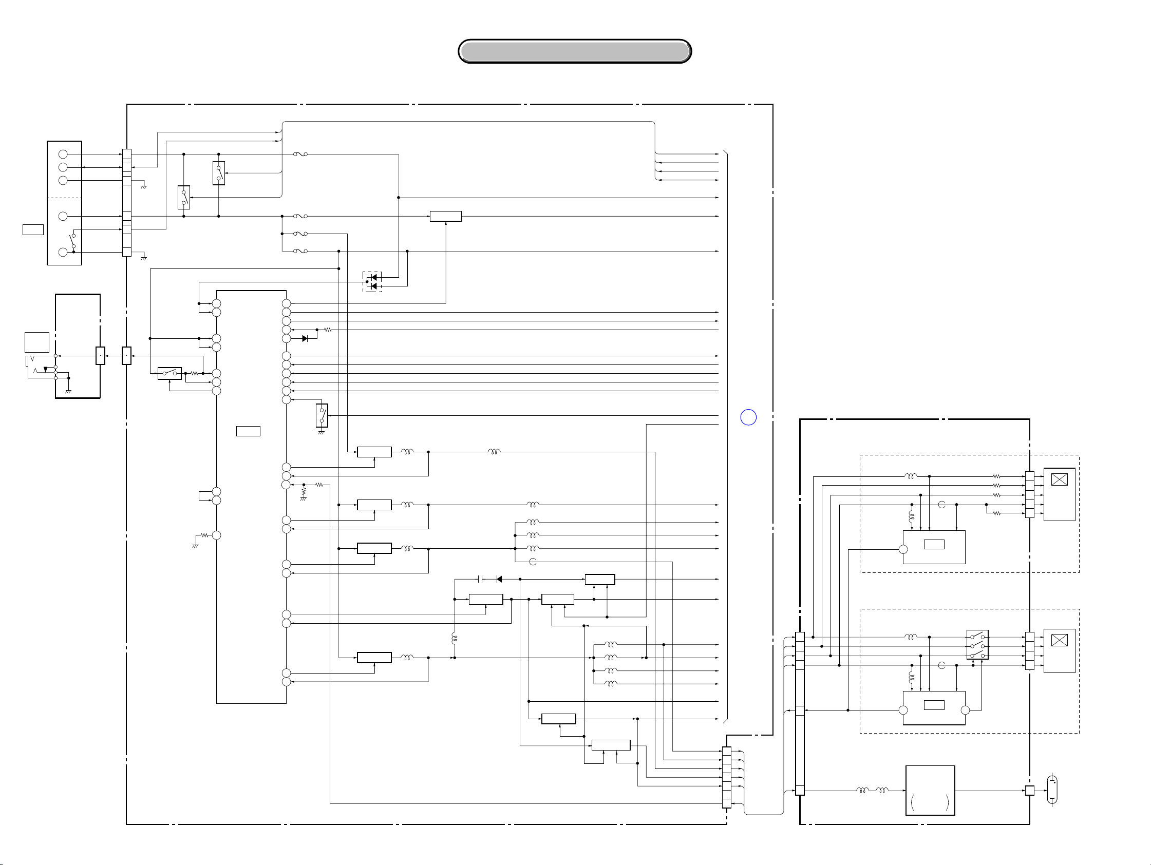
3-3. O VERALL BLOCK DIAGRAM (3/5)
VC-341 BOARD (3/4)
OVERALL (2/5)
(PAGE 3-3)
OVERALL (1/5)
(PAGE 3-2)
OVERALL (2/5)
(PAGE 3-4)
OVERALL (1/5)
(PAGE 3-2)
OVERALL (1/5)
(PAGE 3-1)
OVERALL (2/5)
(PAGE 3-4)
OVERALL (2/5)
(PAGE 3-3)
OVERALL (2/5)
(PAGE 3-4)
OVERALL (4/5)
(PAGE 3-8)
11
13
12
15
19
XRST VTR
XCS IC 301
XRST VTR
XCS IC 301
2
CAM DD ON
EVF DD ON
XCS LCD
VC SO, VC SI, XVC SCK VC SO, VC SI, XVC SCK
VC SO, VC SI, XVC SCK
CS CH, CH SO, CH SCK
IRIS PWM
XNS SW
5
4
9
HALL AD
PITCH AD
YAW A D
XCS AU
BEEP
DCOUT JACK IN
AV JACK IN
XS JACK IN
IR ON
ZM RST LED
FC RST LED
LENS TEMP AD
AGC SLOW
BOTH REC
RP PB MODE
DOP
DA STRB
AFC F0
XFE ON
RF SWP
VIVDO
XCS OSD, OSD SO, XOSD SCK
IC701 SO, IC701 SI, IC701 SCK, XCS IC701
CUSTOM LED ON
ZOOM VR AD
DCOUT ON
OSD V
XSYS RST
XCC DOWN
( ) : Number in parenthesis ( ) indicates the division number of schematic diagram where the component is located.
IC401 (3/3)
34
44
41
38
36
3716
LCD HOLD
X1/2 SWP
XSG V RST
ATF SAMPLE
SWP DIR
CK CONT1, 2
XTBC V RST
CK CONT1, 2
(5/10)
LPF
SERIAL
INTERFACE
JOG VD
SYS V
TBC VD
SYS V
45
43
35
10
17
20
DRUM ERROR
CAP ERROR
CL
OVERALL (2/5)
(PAGE 3-3)
OVERALL (1/5)
(PAGE 3-2)
OVERALL (4/5)
(PAGE 3-8)
25
IC051 (1/2)
6
DRUM/CAPSTAN
9
24
16
PWM
DRIVE
(9/10)
OVERALL (1/5)
(PAGE 3-2)
SWITCHING
SWITCHING
VL 16V
Q061
Q060
TAPE LED ON
VIDEO LIGHT
DRIVE
62
61
X601
20MHz
162
109
110
128
129
130
200
111
185
186
194
127
168
169
203
117
170
159
206
133
115
208
61
76
26
75
77
78
71
ı
IC601
73
CAMERA/
93
MECHA
CONTROL
(6/10)
62
49
50
11
10
46
80
ı
82
3
1
63
ı
66
52
9
8
88
89
197
198
165
166
190
118
209
ı
211
18
17
15
20
19
119
120
201
213
212
214
163
155
157
154
156
134
173
204
181
158
95
96
179
205
VC SO, XVC SCK
DRUM FG
DRUM PG
CAP ON
CAP FWD
CAP FG
DEW AD
MODE SW A-C
LOAD
UNLOAD
LM LIM DET
TAPE END
TAPE TOP
T REEL FG
S REEL FG
TAPE LED ON
REC PROOF
ME SW
HI8 MP SW
DRUM PWM
CAP PWM
XCS IC401
MECHA FLD, MECHA HD, MECHA VD
Q001
DRUM VS
DRUM FG
DRUM PG
CAP VS
CAP FWD
CAP FG
UNLOAD
LM LIM DET
TAPE END
TAPE TOP
T REEL FG
S REEL FG
Q401
LED DRIVE
64
67
53
50
75
77
CAP ON
80
1
4
LOAD,
32
33
31
21 20
19
28
24
IC401 (1/3)
MOTOR
FG AMP
PG AMP
CAPSTAN
MOTOR
FG AMP
IC401 (2/3)
(5/10)
LOADING
MOTOR
DRIVE
TAPE END
DETECT
TAPE TOP
DETECT
T REEL
FG AMP
S REEL
FG AMP
CN009
(2/2)
(5/10)
DRUM
DRIVE
DRIVE
1 30
63
65
68
52
49
74
CAP U, V, W
76
78
10
ı
15
7
8
MODE SW A-C
LM (+) , LM (–)
69
72
TAPE END (C)
TAPE TOP (C)
18
T REEL (+) , (–)
26
27
S REEL (+) , (–)
22
23
TAPE LED (K)
REC PROOF
HI8 MP SW
XCC DOWN
SI-039 BOARD
(2/2)
CN755
(2/2)
VL+
U, V, W
HU1, 2
HV1, 2
HW1, 2
FG1, 2
DEW AD
ME SW
CN402
FG
PG
CN403
CN401
CN404
LND756
M2100/M2101 MECHA DECK (2/2)
M2100: TRV128/TRV228/TRV328/TRV428
M2101: TRV228E/TRV428E
M901
10
ı
5
3
1
14
ı
9
7
ı
2
18
16
22
21
ı
19
2
1
2
1
9
10
7
6
3
13
12
14
15
DRUM MOTOR
M
DRUM FG
DRUM PG
M902
CAPSTAN MOTOR
M
HU, HV, HW
CAPSTAN FG
DEW SENSOR
S901
MODE SWITCH
M903
LOADING MOTOR
M
Q002
TAPE END
SENSOR
Q001
TAPE TOP
SENSOR
T REEL
SENSOR
S REEL
SENSOR
S001
S002
H001
H002
REC PROOF
ME/MP
HI8 MP
C. C. LOCK
FP-792 FLEXIBLE
BOARD
D001 – 003
(VIDEO LIGHT)
D001
TAPE
LED
V LIGHT PWM
IC602
EEPROM
(6/10)
2 5 6
EEP SI, EEP SO, EEP SCK
1
XCS EEP
05
91
87
86
EEP SI, EEP SO, EEP SCK
84
XCS EEP
85
XCS EEP
CAP FG
SWP DIR
EEP SI, EEP SO, EEP SCK
CN007
(2/3)
16
4
5
15
(FOR CHECK)
14
1
CPC
A : SERVO SIGNAL
3-5 3-6
Page 21
CCD-TRV128/TRV228/TRV228E/TRV328/TRV428/TRV428E
3. BLOCK DIAGRAMS
3. BLOCK DIAGRAMS
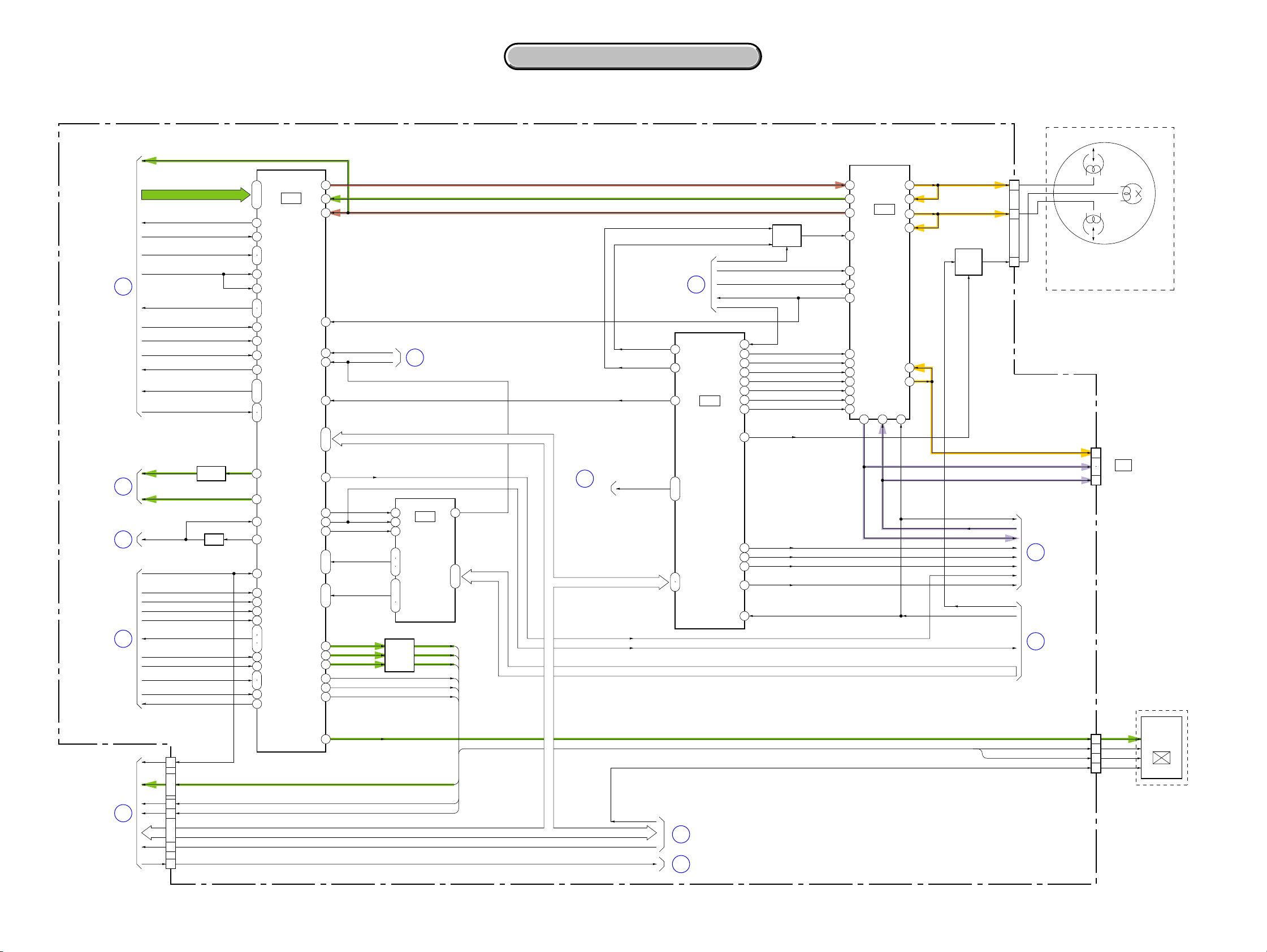
3-4. O VERALL BLOCK DIAGRAM (4/5)
VC-341 BOARD (4/4)
CN007
(3/3)
12
11
13
CN002
(2/2)
20
20
CN006
1
4
3
16
6
8
9
12
CN005
19
20
5
14
18
16
6
22
Q002
LED
9
DRIVE
3
LI 3V
CN6005
1
2
PD-204 BOARD (1/2)CONTROL KEY
AD5
BLOCK (PR-5100)
S601
PANEL
REVERSE
SW
CONTROL KEY BLOCK (SS-5100)
S001
START/STOP
SW
(CHG)
S004
POWER
OFF
ON
>
MODE
D004
CHG
D002
CAMERA
D001
PLAY/EDIT
S002
EJECT SW
RV001
ZOOM VR
CONTROL KEY BLOCK (CF-5100) (2/2)
S024
SEL/PUSH
EXEC
DIAL
MENU EXEC
D002
EASY
DIAL A, B
FUNCTION
SW
S001
DISP/
BATT INFO SW
S002
RESET SW
BT001
LITHIUM
BATTERY
CPC
(FOR CHECK)
CN6001
(1/2)
XS/S SW
XPOWERSW
XMODE SW
XEJECT SW
XCHARGE LED
XCAM LED
XVTR LED
ZOOM VR
KEY AD0 – KEY AD3
CUSTOM LED ON
( ) : Number in parenthesis ( ) indicates the division number of schematic diagram where the component is located.
LANC IN
LANC OUT
XLANC POWER ON
KEY AD5
KEY AD7
XPOWER SW
XMODE SW
XEJECT SW
XCHARGE LED
XCAM LED
XVTR LED
ZOOM VR AD
DIAL A, B
KEY AD0 – KEY AD3
XBATT INFO SW
XRESET
X701
10MHz
X702
32.768kHz
39
40
8
29
28
52
51
67
69
1
2
4
12
11
9
79
80
59
ı
61
65
3
73
IC701
HI CONTROL
(7/10)
45
41
10
32
20
21
31
35
49
74
37
38
43
42
5
47
23
ı
26
19
Q701
BATTERY
CHARGE
DETECTOR
IC 701 SO, IC 701 SI, IC 701 SCK, XCS IC 701
SIRCS PWM
SIRCS SIG
XF TALLY LED
SYS V SYS V
HI EVER SO, HI EVER SCK
BATT IN
VTR DD ON
XCS DD
BATT/XEXT
FAST CHARGE
INIT CHARGE ON
BATT SIG
XCC DOWN
XSYS RST
OSD V
BL REG
D 1.5V
A 2.8V
D 2.8V
AU 2.8V
EP 2.8V
A 4.6V
AU 4.6V
EP 4.6V
RP 4.6V
MT 5V
VL 16V
CAM –7.5V
CAM 15V
EP 13.5V
PANEL –15.3V
EVER 3.0V
VOUT
LANC DC
D053
XRESET
VBAT
REG 3V
DC CONTROL,
27
28
44
38
26
45
39
40
14
IC051 (2/2)
RESET
(9/10)
47
IC 701 SO, IC 701 SI, IC 701 SCK, XCS IC 701
VTR UNREG
BATT UNREG
Q075
SIRCS PWM
SIRCS SIG
XF TALLY LED
BL CONT
DCOUT ON
XCC DOWN
XSYS RST
OSD V
OVERALL (1/5)
8
OVERALL (3/5)
20
OVERALL (2/5)
14
Q053, 054 Q051, 052
CHARGE
CONTROL
INIT CHARGE ON
OVERALL (3/5)
19
(PAGE 3-2)
(PAGE 3-5)
(PAGE 3-4)
FAST CHARGE
(PAGE 3-5)
BATT/XEXT
BATT SIG
CN053
BT901
4
+
–
+
S
–
DC IN
BATTERY
TERMINAL
3
2
6
5
1
ZOOM VR AD
CUSTOM LED ON
05
3-7 3-8
ZOOM VR AD
CUSTOM LED ON
Page 22
3. BLOCK DIAGRAMS
3. BLOCK DIAGRAMS
CCD-TRV128/TRV228/TRV228E/TRV328/TRV428/TRV428E
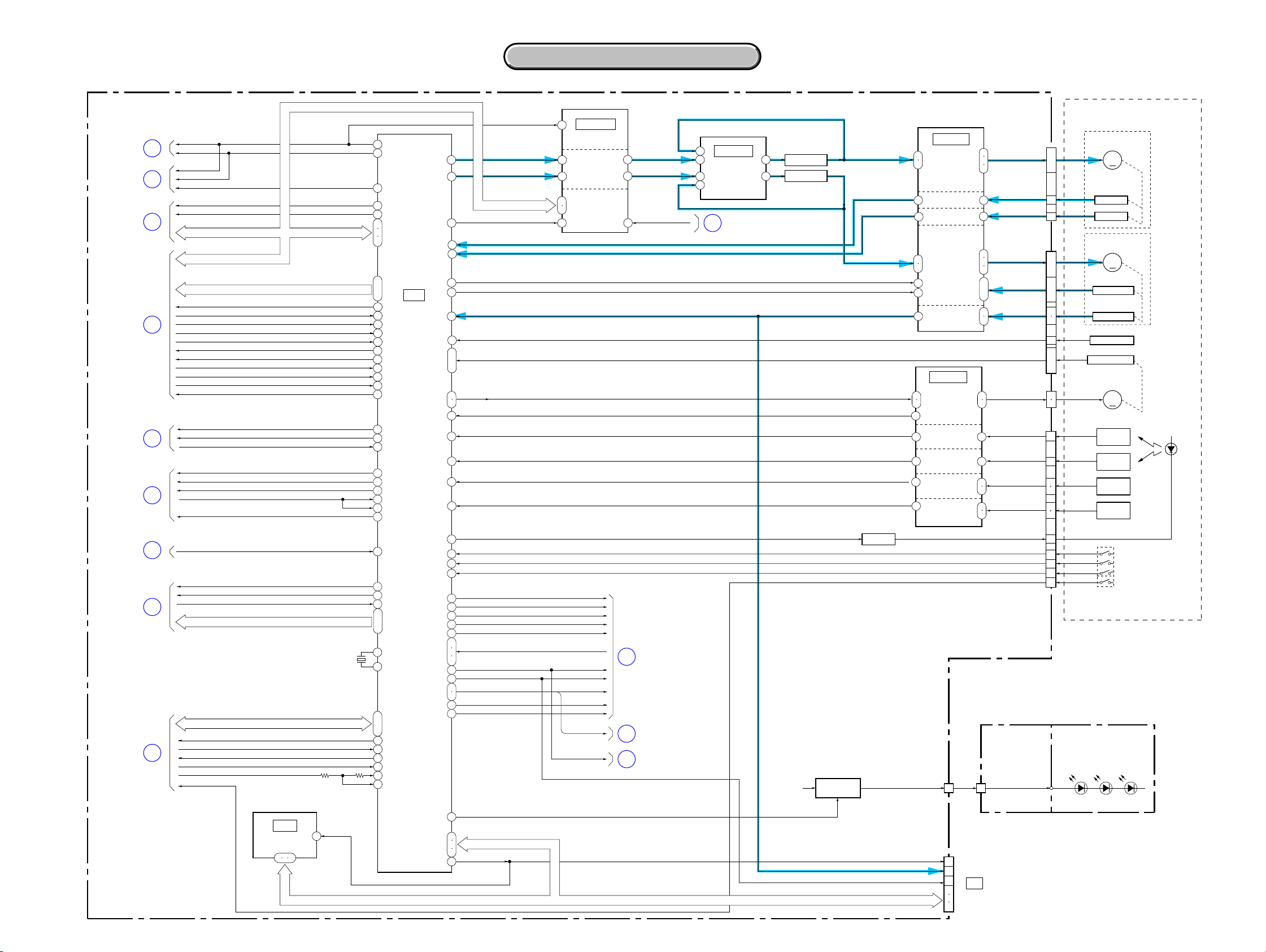
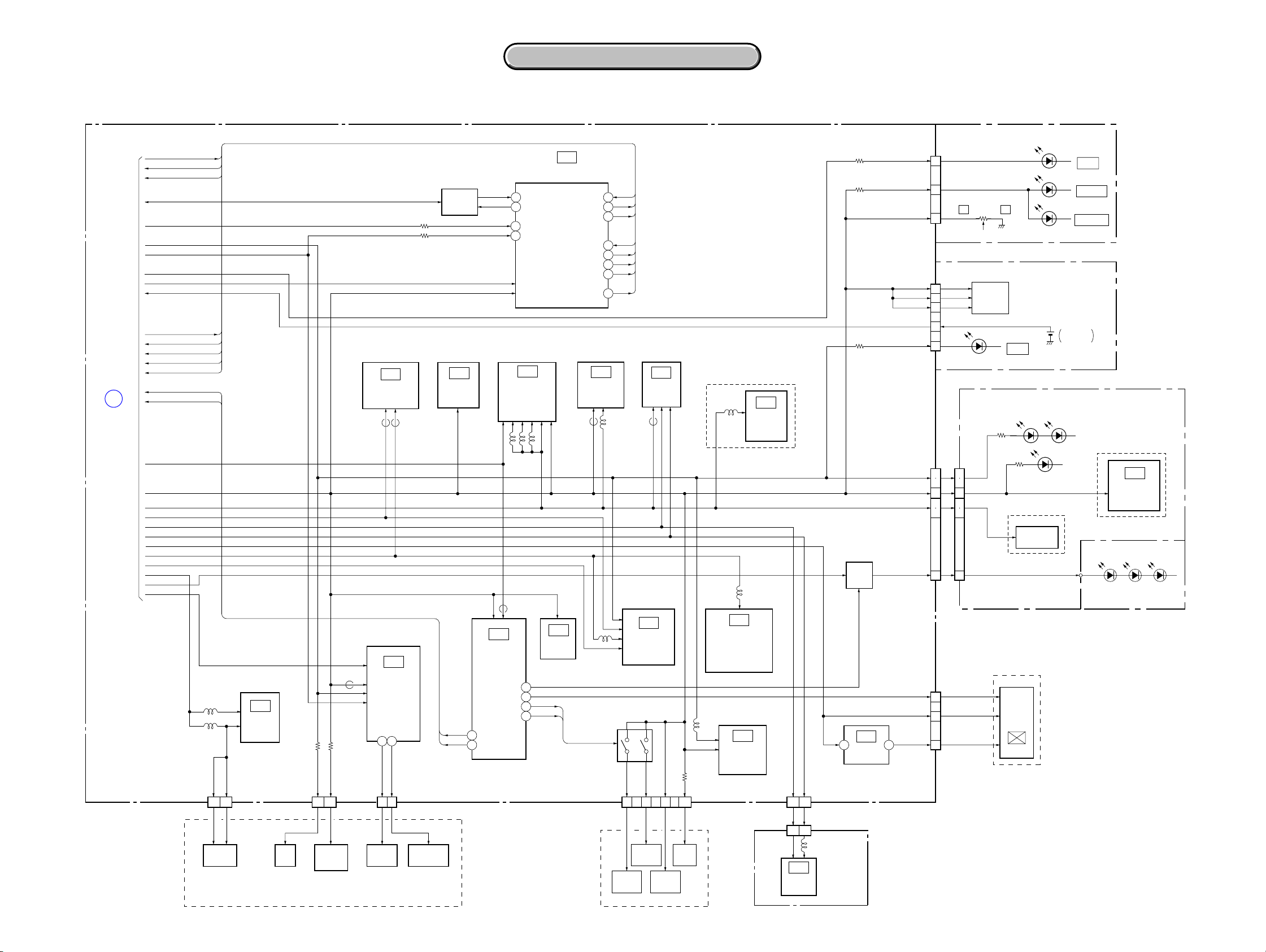
3-5. O VERALL BLOCK DIAGRAM (5/5)
PD-204 BOARD (2/2)
CN6001
(2/2)
PANEL R, PANEL G, PANEL BPANEL R, PANEL G, PANEL B
7
ı
5
OVERALL (2/5)
(PAGE 3-3)
18
XCS LCD DA
VC SO, VC SI, XVC SCK VC SO, VC SI, XVC SCK
C-SYNC/XHD
PANEL XVD
PANEL HOLD
BL CONT BL CONT
10
11
ı
13
9
8
14
4
XCS LCD DA
C-SYNC/XHD
PANEL XVD
PANEL HOLD
( ) : Number in parenthesis ( ) indicates the division number of schematic diagram where the component is located.
TYPE C/S: Please refer to page 1-3
to discriminate the type of LCD.
NOTE: CN6004 Pin Name A/B
A: TYPE C MODEL
B: TYPE S MODEL
CN6004
40
ı
38
IC6001
45
46
48
43
42
28
LCD
DRIVER
ı
1
2–6
14–16
29
32–35
19
ı
21
23
N.C./SPC, GRES/EX1, GPCK/MO1, GSRT/MO2,
STBYB/PSG,RESET/EX2, VBC/CLS, STBYB/RES,
SRT/PSS1, OE/PSS2, CLR/CTR, MCLK/CLD, HCNT/SPD
T6001, Q6002
INVERTER
BL REG
BL DET
30
TRANSFORMER
BACKLIGHT
DRIBE
D6004
VR, VG, VB
VCOM
BL HIGH
BL LOW
CN6003
19
ı
21
11
5
ı
10
12
ı
18
10
3
LCD901
2.5 INCH
COLOR
LCD UNIT
ND901
BACKLIGHT
05
A : VIDEO SIGNAL
3-9 3-10
Page 23
CCD-TRV128/TRV228/TRV228E/TRV328/TRV428/TRV428E
3. BLOCK DIAGRAMS
3. BLOCK DIAGRAMS
3-6. POWER BLOCK DIAGRAM (1/2)
VC-341 BOARD (1/2)
CN053
6
5
1
4
2
3
CN009
(1/2)
28
29
05
Q055
Q053, 054
CHARGE
CONTROL
Q051, 052
43
36
55
56
54
53
52
37
1
30
VIN
CDET
VCC1
VCC0
LANC DC
SENS
VCONT
VREF
DTC6
RT
INIT CHARGE ON
DC CONTROL,
DC IN
J753
RFU DC
OUT
BT901
BATTERY
TERMINAL
+
S
–
+
–
SI-039
BOARD
(1/2)
CN755
RFU DC
BATT UNREG
BATT SIG
BATT GND
ACV UNREG
BATT/XEXT
ACV GND
(1/2)
3
2
( ) : Number in parenthesis ( ) indicates the division number of schematic diagram where the component is located.
BATT SIG
BATT/XEXT
FAST CHARGE
REG 3V
XCTL2
IC051
RESET
(9/10)
VRO
VOUT
VBAT
DIN
CLK
CTL1
OUT2
+INE2
OUT1
OUT3
IN3
OUT7
–INE7
OUT4
IN4
F002
L052
L055
L056
L057
Q063, 065, 069
5V REG
L051
L059
D055
Q062
SWITCHING
BL REG
L058
L061
L060
L062
FB051
Q066, 073
–7.5V REG
Q064, 067, 070
+15V REG
L065
L063
L064
L066
Q071, 072
13.5V REG
Q068, 074
–15.3V REG
F003
F004
F001
VTR UNREG
VR
34
41
42
39
40
D053
CS
44
LD
26
27
28
38
47
Q075
58
21IN2
14
57
20IN1
59
22
63
2
60
23
D054
Q057
SWITCHING
Q056
SWITCHING
Q058
SWITCHING
Q059
SWITCHING
BL CONT
BATT/XEXT
FAST CHARGE
INIT CHARGE ON
BATT UNREG
VTR UNREG
EVER 3.0V
HI EVER SO
HI EVER SCK
VTR DD ON
DCOUT ON
CAM DD ON
CAM –7.5V
PANEL –15.3V
PANEL 13.5V
BATT SIG
MT 5V
V OUT
LI 3V
BATT IN
XCS DD
D 1.5V
D 2.8V
A 2.8V
AU 2.8V
CAM 15V
EP 4.6V
A 4.6V
AU 4.6V
RP 4.6V
VL 16V
EP 13.5V
CN002
PANEL 2.8V
PANEL 4.6V
BL REG
BL CONT
POWER(2/2)
(PAGE 3-13)
17
18
2
16
19
4
A
TYPE C/S: Please refer to page 1-3 to descriminate the type of LCD.
PD- 204 BOARD
TYPE C
LCD901
24
3
2.5INCH
1
COLOR
23
LCD UNIT
4
LCD901
24
3
2.5INCH
1
COLOR
23
LCD UNIT
ND901
10
BACK
LIGHT
18
16
19
17
4
2
BL REG
CN6001
PANEL 4.6V
PANEL –15.3V
PANEL 13.5V
PANEL 2.8V
BL CONT
TYPE S
PANEL 4.6V
PANEL –15.3V
PANEL 13.5V
PANEL 2.8V
BL CONT
L6002 L6003
L6004
L6001
28
L6004
L6001
FB6001
IC6001
LCD DRIVER
FB6001
IC6001
LCD DRIVER
T6001, Q6002
INVERTER
TRANSFORMER
BACKLIGHT
DRIVE
R6026
R6019
R6020
Q6004, 6005,
6008, 6009
2428
BL HIGH
R6031
CN6004
VSH
VGL
VGH
VDD
VDD
CN6004
VSH5V
VGL
VGH
VSH3V
CN6003
3-11 3-12
Page 24
3. BLOCK DIAGRAMS
3. BLOCK DIAGRAMS
CCD-TRV128/TRV228/TRV228E/TRV328/TRV428/TRV428E
3-7. POWER BLOCK DIAGRAM (2/2)
VC-341 BOARD (2/2)
BATT/XEXT
FAST CHARGE
INIT CHARGE ON
BATT SIG
BATT UNREG
MT 5V
VTR UNREG
EVER 3.0V
VOUT VOUT
LI 3V
BATT IN
XCS DD
HI EVER SO
HI EVER SCK
VTR DD ON
DCOUT ON
A
POWER (1/2)
(PAGE 3-12)
CAM DD ON
D 1.5V
D 2.8V
A 2.8V
AU 2.8V
CAM –7.5V
CAM 15V
EP 4.6V
A 4.6V
AU 4.6V
RP 4.6V
VL 16V
EP 13.5V
L483
L481
IC481
REC/PB
AMP
(4/10)
VTR UNREG
( ) : Number in parenthesis ( ) indicates the division number of schematic diagram where the component is located.
IC701
HI CONTROL
L303
EEPROM
(7/10)
BATT/XEXT
FAST CHARGE
INIT CHARGE ON
BATT IN 31
XCS DD 49
HI EVER SO
HI EVER SCK 21
VTR DD ON
A/D CONVETER
FB152 FB151L151
IC602
(6/10)
IC152
S/H. AGC.
(1/10)
L801
74
37
38
20
35
Q202
IC151
TIMING
GENERATOR
(1/10)
IC801
AUDIO/VIDEO
PROCESS
(8/10)
TRV328/TRV428/TRV428E
IC271
L271
STEADY
(10/10)
CAM –7.5V
L202
IC202
IRIS DRIVE,
HALL BIAS CONTROL,
HALL GAIN CONTROL,
HALL AMP
(3/10)
L201
IC201
FOCUS/ZOOM
MOTOR DRIVE
(3/10)
SHOT
MT 5V
D 2.8V
A 2.8V
CAM 15V
EP 4.6V
MT 5V
D 2.8V
FB401
IC251
EVR
(D/A CONVERTER)
(4/10)
FB251
IC401
DRUM/
CAPSTAN/
LOADING
MOTOR DRIVE
(5/10)
VMR
VH
3 17
Q701
BATTERY
CHARGE
DETECTOR
D 2.8V
EVER 3.0V
LI 3V
IC302
CHARACTER
GENERATOR
(2/10)
FB252
D 1.5V
MT 5V
D 2.8V
A 2.8V
AU 2.8V
CAM –7.5V
CAM 15V
EP 4.6V
A 4.6V
AU 4.6V
VL UNREG VL UNREG
CAMERA/MECHA
115
162 CAM DD ON
PROCESS, ATF,
LENS CONTROL
IC601
CONTROL
(6/10)
V LIGHT PWM
DCOUT ON
43
IB SI
IB SO
42
54
BATT SENSE
55
ACV SENSE
IC301
CAMERA/VTR
(2/10)
L301
L302
FB601
91
26EVF DD ON
49ZM RST LED
50FC RST LED
EVER 3.0V
D 2.8V
MT 5V
1 4
CHARGE LED VDD
CUSTOM LED VDD
Q001
VIDEO
LIGHT
DRIVE
V LIGHT PWM
IC001
3.3V REG
(10/10)
MODE LED VDD
D 2.8V
D 2.8V
D 2.8V
D 2.8V
LI 3V
MT 5V
D 2.8V
A 2.8V
VL+
EVF DD ON
EP 4.6V
3.3V
CONTROL KEY BLOCK (SS-5100)
CN006
5
10
RV001
11
CN005
17
15
4
3
7
(ZOOM)
CONTROL KEY BLOCK (CF-5100)
FUNCTION
SWITCH
SI-039 BOARD
(2/2)
CN009
(2/2)
CN004
141517
12
9
10
1 30
NSLEEP
2
EVF 4.6V
3
1
16
19
22
21
3.3V
CN755
(2/2)
WT
D002
EASY
D753, 754
(IR EMITTER)
D759
(TALLY)
TRV328/TRV428/TRV428E
SE751, 752
YAW, PITCH
SENSOR
LND756
EVF BLOCK
LCD902
B/W
LCD
UNIT
D004
CHG
D002
CAMERA
D001
PLAY/EDIT
BT001
LITHIUM
BATTERY
TRV228/TRV228E/TRV328/
TRV428/TRV428E
COMMANDER
RECEIVER
FP-792 FLEXIBLE BOARD
D001 – 003
(VIDEO LIGHT)
IC751
REMOTE
FG VCC
17
CAPSTAN
FG
VH+
HU, HV, HW
SENSOR VCC
05
CN481
4 8
VIDEO
HEAD
TAPE
LED
D001
SP2Y
SP1Y
M2100/M2101 MECHA DECK
TAPE LED (A)
CN404 CN403
4 8 8
T REEL,
S REEL,
SENSOR
H001,002
M2100: TRV128/TRV228/TRV328/TRV428
M2101: TRV228E/TRV428E
CN201
VCC
FOCUS
SENSOR
ZOOM
SENSOR
LENS BLOCK
TEMP
18 241613
TEMP
SENSOR
IRIS DRIVE(+)
IRIS
METER
CN151
CN951
CAM –7.5V
CAM 15V
12 10
3 5
IC951
CCD
IMAGER
L951
CD-465
BOARD
ZM SENS
VCC
FC SENS
3-13 3-14E
Page 25
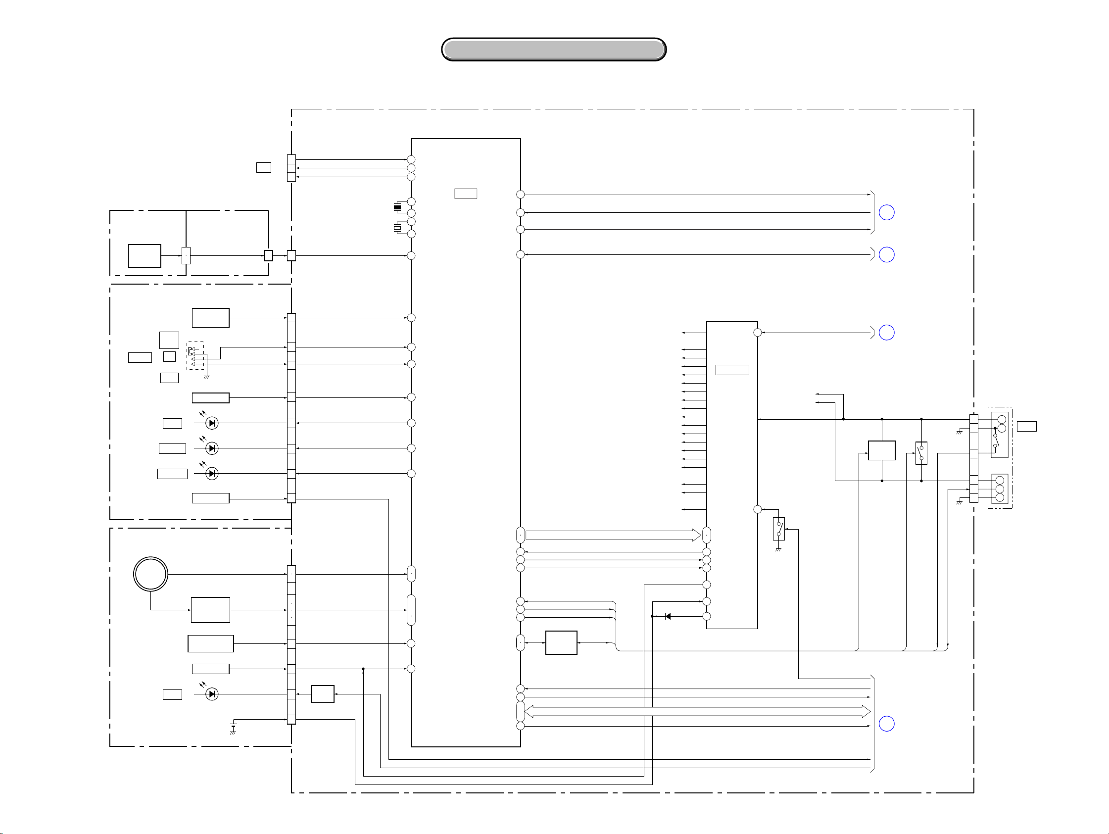
PRINTED WIRING BOARDS AND SCHEMATIC DIAGRAMS
4-1. FRAME SCHEMATIC DIAGRAMS
SECTION 4
4-2. SCHEMATIC DIAGRAMS 4-3. PRINTED WIRING BOARDS
4-2. SCHEMATIC DIAGRAMS 4-3. PRINTED WIRING BOARDS
CCD-TRV128/TRV228/TRV228E/TRV328/TRV428/TRV428E
1
FRAME SCHEMATIC DIAGRAM
A
2 10
B
LENS
C
D
E
FP-792
F
G
H
I
FLEXIBLE
BOARD
VL+
REG_GND
REG_GND
LND759
LND756
LND760
MIC901
MICROPHONE
MIC_GND
LND754
SI-039
BOARD
J
K
L
CONTROL
M
(PR-5100)
N
05
34 1814
CD-465
BOARDBLOCK
INT_MIC
LND755
24PCN201
IRIS_HALL(+)
IRIS_DRIVE(+)
XF_TALLY_LED
SIRCS_PWM/IR_DRV_EN
DCOUT_JACK_IN
IRIS_BIAS(+)
CN755
MIC_GND
MIC_GND
INT_MIC
XSIRCS_SIG
AV_JACK_IN
AUDIO_L_I/O
REG_GND
VIDEO_I/O
REG_GND
S_Y_I/O
REG_GND
XS_JACK_IN
REG_GND
S_C_I/O
REG_GND
RFU_DC
RFU_DC
IRIS_BIAS(-)
IRIS_HALL(-)
30P
VL+
LIA1
VREF1
LIA2
VREF2
A_2.8V
A_2.8V
D_2.8V
MT_5V
MT_5V
TEMP
IRIS_DRIVE(-)
30
29
28
27
26
25
24
23
22
21
20
19
18
17
16
15
14
13
12
11
10
9
8
7
6
5
4
3
2
1
TEMP
KEY
BLOCK
5 12
CN951
14P
V4
14
V3
13
V2
12
V1
11
GND
10
9
H2
8
H1
7
RG
GND
LENS_DET
ZM_SENSE_VCC
ZM_SENSE_OUT
FP-795 FLEXIBLE
6
5
4
3
2
1
GND
FC_SENSE_VCC
FC_SENSE_OUT
VL+
1
MIC_GND
2
MIC_GND
3
INT_MIC
4
LIA1
5
VREF1
6
LIA2
7
VREF2
8
A_2.8V
9
A_2.8V
10
XF_TALLY_LED
11
D_2.8V
12
XSIRCS_SIG
13
MT_5V
14
MT_5V
15
SIRCS_PWM/IR_DRV_EN
16
AV_JACK_IN
17
AUDIO_L_I/O
18
REG_GND
19
VIDEO_I/O
20
REG_GND
21
S_Y_I/O
22
REG_GND
23
XS_JACK_IN
24
REG_GND
25
S_C_I/O
26
REG_GND
27
RFU_DC
28
RFU_DC
29
DCOUT_JACK_IN
30
SE_GND
SE_GND
N.C.
N.C.
PANEL_REV
PANEL_REV
CAM_15V
CAM_-7.5V
CCD_OUT
101112131415161718192021222324
ZOOM_A
30PCN009
6PCN6005
VSHT
GND
ZOOM_B
ZOOM_XB
6
5
4
3
2
1
ZOOM_XA
IR_SWITCH
IR_SWITCH
20P
CN002
20P
CN6001
FOCUS_A
FOCUS_B
AD5
AD5
FOCUS_XB
PANEL_13.5V
PANEL_13.5V
FFC-005 FLEXIBLE
FLAT CABLE
123456789
FOCUS_XA
PANEL_4.6V
PANEL_2.8V
PANEL_2.8V
PANEL_4.6V
14PCN151
CCD_OUT
PANEL_-15.3V
REG_GND
REG_GND
PANEL_-15.3V
GND
CAM_-7.5V
PANEL_HOLD
PANEL_HOLD
VSHT
VC_SI(HDO)
VC_SO
PD-124
HARNESS
VC_SO
VC_SI(HDO)
1011121314
GND
CAM_15V
CPC
(FOR CHECK)
XVC_SCK
XVC_SCK
C-SYNC/XHD
XCS_LCD_DA
9
1011121314151617181920
9
1011121314151617181920
C-SYNC/XHD
XCS_LCD_DA
PD-204
BOARD
When the machine needs to be repaired,please refer to
page 1-3 to discriminate the type of LCD(TYPE C or TYPE S).
H2RGH1
PANEL_R
PANEL_XVD
8
8
PANEL_R
PANEL_XVD
GND
16
15
14
13
12
11
10
9
8
7
6
5
4
3
2
1
PANEL_G
PANEL_G
16PCN007
XCS_EEP
EEP_SI
EEP_SO
XLANC_PWR_ON
LANC_IN
LANC_OUT
REG_GND
PB_RF
REG_GND
REC_RF
REG_GND
SWP_DIR
CAP_FG
BPF_MONI
PB_RF
EEP_SCK
BL_CONT
PANEL_B
PANEL_B
BL_CONT
123456789
V4
V3V1V2
SE_GND
BL_GND
BL_REG
1234567
1234567
BL_REG
BL_GND
SE_GND
9
TAPE_TOP(C)
TAPE_LED(A)
TAPE_END(C)
REG_GNDREG_GND
TAPE_LED(K)
123456789
15P
CN404
TAPE_LED(K)
TAPE_LED(A)
TAPE_TOP(C)
TAPE_END(C)
123456789
24P
VGL/VGL
VSS/GND
VGH/VGH
VDD/VGLAC
CN6004
S_REEL(-)
S_REEL(-)
N.C./SPS
SENSOR_VCC
T_REEL(+)
T_REEL(-)
HALL_COM
ME/MP
REC_PROOF
HI8_MP
C_LOCK_SW
S_REEL(+)
FP
HALL_COM
ME/MP
HI8_MP
REC_PROOF
15
C_LOCK_SW
S_REEL(+)
T_REEL(+)
SENSOR_VCC
1011121314
T_REEL(-)
VC-341 BOARD
LCD901
2.5INCH
COLOR
LCD UNIT
101112131415161718192021222324
GPCK/MO1
GSRT/MO2
STBYB/PSG
RESET/EX2
VBC/CLS
VCOM/VCOM
SRT/PSS1
STBYB/RES
GRES/EX1
11 15
M2100/M2101 MECHANISM DECK
CAP_W
CAP_W
CAP_U
22P
CN403
DEW
DEW
OE/PSS2
M-SW(A)
M-SW(B)
M-SW(A)
M-SW(B)
CLR/CTR
MCLK/CLD
CN6004 Pin Name A/BNote:
A:
TYPE C MODEL
B: TYPE S MODEL
M-SW(C)
M-SW(C)
HCNT/SPD
FG2
FG VCC
REG_GND
FG1
FG1
FG2
FG VCC
REG_GND
VB/VB
VR/VR
VG/VG
VSS/GND
CAP_U
VSH/VSH5V
VDD/VSH3V
CAP_U
CAP_U
CAP_V
FP
10111213141516171819202122
CAP_V
CAP_W
CAP_W
13 17
HV2
HW1
HU1
HV1
HU2
HU2
10
BL_HIGH
N.C
HV1
BACKLIGHT
N.C
ND901
HW2
VH-
FE(X)
123456789
11
11PCN481
VH-
HV2
HW1
HW2
FE(X)
N.C
N.C
N.C
N.C
LED
BL_LOW
CAP_V
CAP_V
VH+
VH+
HU1
10PCN6003
FE(Y)
10
FE(Y)
GND
GND
123456789
LED_GND
M2100: TRV128/TRV228/TRV328/TRV428
M2101: TRV228E/TRV428E
1916678
20
21
EVF BLOCK
LCD902
B/W
LCD
UNIT
LM
SP1X
SP1Y
GND
SP2Y
SP2X
SP2Y
SP2X
GND
GND
GND
FP
GND
SP1X
SP1Y
2PCN008
SP901
SPEAKER
GND
GND
SP(+)
SP(-)
1
2
U
123456789
10
U
10P
GND
CN402
22PCN005
REG_GND
N.C
123456789
COM
PG
FG
V
W
W
V
U
V
V
U
LI_3V
D_2.8V
FG-PG_COM
FP
W
KEY_AD0
123456789
W
FG
PG
COM
FG-PG_COM
N.C
XCUSTOM_LED_ON
BATT_INFO
REG_GND
CUSTOM_LED_VDD
XMS_LED
10111213141516171819202122
N.C
2
2P
LM(+)
CN401
MS_LED_VDD
KEY_AD1
1
LM(-)
D_2.8V
KEY_AD3
D_2.8V
XPOWER_SW
CHARGE_LED_VDD
XCHARGE_LED
MODE_LED_VDD
BATT_UNREG
KEY_AD2
DIAL_A
CN006
XS/S_SW
REG_GND
XMODE_SW
XCAM_LED
XVTR_LED
ZOOM_VR
REG_GND
XEJECT_SW
BATT_GND
BATT/XEXT
ACV_GND
ACV_UNREG
BATT_SIG
DIAL_B
N.C
D_2.8V
REG_GND
16P
N.C
N.C
XRESET
NC
NC
8PCN004
13.3V
2NSLEEP
3EVF_4.6V
4HSYNC
5VSYNC
6VIDEO_IN
7DIG_GND
8ANA_GND
1
2
3
4
5
6
7
8
9
10
11
12
13
14
15
16
6PCN053
1
2
3
4
5
6
10
FP-797
FLEXIBLE
CONTROL
KEY
BLOCK
(SS-5100)
BT901
BATTERY
TERMINAL
3.3V3NSLEEP4EVF_4.6V5HSYNC6VSYNC7VIDEO_IN8DIG_GND9ANA_GND
1
2
CONTROL
KEY
BLOCK
(CF-5100)
4-1 4-2
FRAME
Page 26
Link
Link
CCD-TRV128/TRV228/TRV228E/TRV328/TRV428/TRV428E
4-2. SCHEMATIC DIAGRAMS
CD-465 BOARD
CD-465 BOARD
VC-341 BOARD (1/10)
VC-341 BOARD (1/10)
(A/D CONVERTER, TIMING GENERATOR)
(A/D CONVERTER, TIMING GENERATOR)
VC-341 BOARD (2/10)
VC-341 BOARD (2/10)
(CAMERA/VTR PROCESS, LENS CONTROL)
(CAMERA/VTR PROCESS, LENS CONTROL)
VC-341 BOARD (3/10)
VC-341 BOARD (3/10)
VC-341 BOARD (4/10)
VC-341 BOARD (4/10)
VC-341 BOARD (5/10)
VC-341 BOARD (5/10)
VC-341 BOARD (6/10)
VC-341 BOARD (6/10)
(CAMERA/MECHA CONTROL)
(CAMERA/MECHA CONTROL)
VC-341 BOARD (7/10)
VC-341 BOARD (7/10)
VC-341 BOARD (8/10)
VC-341 BOARD (8/10)
(CCD IMAGER)
(CCD IMAGER)
(LENS DRIVE)
(LENS DRIVE)
(REC/PB AMP)
(REC/PB AMP)
(SERVO)
(SERVO)
(HI CONTROL)
(HI CONTROL)
(AUDIO, VIDEO)
(AUDIO, VIDEO)
VC-341 BOARD (9/10)
VC-341 BOARD (9/10)
VC-341 BOARD (10/10)
VC-341 BOARD (10/10)
(STEADYSHOT, CONNECTOR)
(STEADYSHOT, CONNECTOR)
PD-204 BOARD
PD-204 BOARD
(LCD DRIVER, BACKLIGHT DRIVE)
(LCD DRIVER, BACKLIGHT DRIVE)
SI-039 BOARD
SI-039 BOARD
FP-792 FLEXIBLE BOARD
FP-792 FLEXIBLE BOARD
FP-228, FP-299, FP-300, FP-301, FP-302,
FP-228, FP-299, FP-300, FP-301, FP-302,
FP-802 FLEXIBLE BOARD
FP-802 FLEXIBLE BOARD
CONTROL KEY BLOCK
CONTROL KEY BLOCK
CONTROL KEY BLOCK
CONTROL KEY BLOCK
CONTROL KEY BLOCK
CONTROL KEY BLOCK
(STEADYSHOT, JACK)
(STEADYSHOT, JACK)
(DC CONTROL)
(DC CONTROL)
(SS-5100)
(SS-5100)
(PR-5100)
(PR-5100)
(CF-5100)
(CF-5100)
COMMON NOTE FOR SCHEMATIC DIAGRAMS
COMMON NOTE FOR SCHEMATIC DIAGRAMS
Page 27
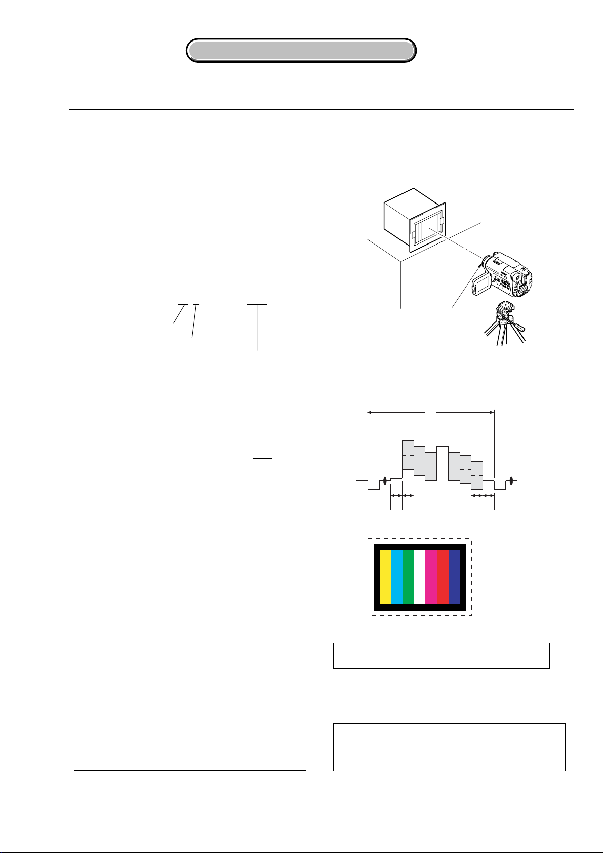
CCD-TRV128/TRV228/TRV228E/TRV328/TRV428/TRV428E
4-2. SCHEMATIC DIAGRAMS
4-2. SCHEMATIC DIAGRAMS
4-2. SCHEMATIC DIAGRAMS
THIS NOTE IS COMMON FOR SCHEMATIC DIAGRAMS
(In addition to this, the necessary note is printed in each block)
(For schematic diagrams)
• All capacitors are in µF unless otherwise noted. pF : µ
Link
µF. 50 V or less are not indicated except f or electrolytics
and tantalums.
• Chip resistors are 1/10 W unless otherwise noted.
kΩ=1000 Ω, MΩ=1000 kΩ.
• Caution when replacing chip parts.
New parts must be attached after removal of chip.
Be careful not to heat the minus side of tantalum
capacitor, Because it is damaged by the heat.
• Some chip part will be indicated as follows.
Example C541 L452
22U 10UH
TA A 2520
Kinds of capacitor
Case size
External dimensions (mm)
• Constants of resistors, capacitors, ICs and etc with XX
indicate that they are not used.
In such cases, the unused circuits may be indicated.
•Parts with ★ differ according to the model/destination.
Refer to the mount table for each function.
• All variable and adjustable resistors have characteristic
curve B, unless otherwise noted.
• Signal name
XEDIT→ EDIT PB/XREC → PB/REC
• 2: non flammable resistor
• 5: fusible resistor
• C: panel designation
• A: B+ Line
• B : B– Line
• J : IN/OUT direction of (+,–) B LINE.
• C: adjustment for repair.
• A: VIDEO SIGNAL (ANALOG)
• A: AUDIO SIGNAL (ANALOG)
• A: VIDEO/AUDIO SIGNAL
• A: VIDEO/AUDIO/SERVO SIGNAL
• A: VIDEO/SERVO SIGNAL
• A: SERVO SIGNAL
• Circled numbers refer to waveforms.
(Measuring conditions voltage and waveform)
•Voltages and waveforms are measured between the
measurement points and ground when camera shoots
color bar chart of pattern box. The y are reference v alues
and reference waveforms.
(VOM of DC 10 MΩ input impedance is used)
•Voltage values change depending upon input
impedance of VOM used.)
1. Connection
Pattern box
1 m
Front of the lens
2. Adjust the distance so that the output waveform of
Fig. a and the Fig. b can be obtain.
H
Yellow
Cyan
White
Magenta
Green
AABBA=B
Fig. a (Video output terminal output waveform)
Fig.b (Picture on monitor TV)
When indicating parts by reference number, please
include the board name.
Red
Blue
Note : The components identified by mark 0 or
dotted line with mark 0 are critical for safety.
Replace only with part number specified.
Note : Les composants identifiés par une marque
0 sont critiques pour la sécurité.
Ne les remplacer que par une pièce portant
le numéro spécifie.
4-5
Page 28
For Schematic Diagram
• Refer to page 4-41 for printed wiring board.
4-2. SCHEMATIC DIAGRAMS CD-465 BOARD
4-2. SCHEMATIC DIAGRAMS CD-465 BOARD
CCD-TRV128/TRV228/TRV228E/TRV328/TRV428/TRV428E
1
342
56
7
89
CD-465 BOARD
A
B
C
D
E
F
G
CCD IMAGER
XX MARK:NO MOUNT
NO MARK:REC/PB MODE
FFC-005 FLEXIBLE
05
R:REC MODE
P:PB MODE
VC-341
(1/10)
CN151
THROUGH THE
FLAT CABLE
(PAGE 4-9)
SIGNAL PATH
REC
VIDEO
SIGNAL
Y/CHROMA
1 IC951 1 REC
V
14PCN951
V4
14
13
V3
12
V2
11
V1
GND
10
H2
9
H1
8
RG
7
GND
6
VSHT
GND
5
4
3
2
1
CAM_15V
CAM-7.5V
CCD_OUT
7.6 Vp-p
L951
C951
22u
100uH
16V
6
IC951 qf REC
ICX437AKA-43:
ICX433AKA-43:
H
2
IC951 2 REC
IC951
CCD IMAGER
IC951
C952
XX
V
TRV128
/TRV228
/TRV328
/TRV428
TRV228E
/TRV428E
Q951
2SC4178-F13F14-T1
BUFFER
3.6 Vp-p
R-7.2
/P0
V41V32V23V1
H2
14
/P0
R1.3
R1.6
R16.1/P0
R952
10
R953
10k
R-7.2/P0
H1
13
/P0
R10.5
/P0
22 Vp-p
R-0.3/P0
R-0.3/P0
4NC5
RG
VL
11
12
/P0.3
/P0.4
R-7.7
R12.6
R11.2
/P0
C953
7
IC951 qd REC
SUB
10
R8.9/P0.1
47u
10V
H
3 IC951 3 REC
V
LND951
C954
XX
R11.2/P0
67
GND
CCD_OUT
NC
VDD
8
9
R15.1/P0
C955
0.1u
4
5
9
8
3.6 Vp-p
7.6 Vp-p
IC951 4 REC
V
IC951 7 REC
H
IC951 q; REC
H
IC951 qs REC
NTSC: 9.54 MHz
PAL: 9.46 MHz
22 Vp-p
1.2 Vp-p
23 Vp-p
2.4 Vp-p
Precautions for Replacement of CCD Imager
• The CD-465 board mounted as a repair part is not equipped
with a CCD imager.
When replacing this board, remove the CCD imager from the
old one and mount it onto the new one.
• If the CCD imager has been replaced, carry out all the
adjustments for the camera section.
• As the CCD imager may be damaged by static electricity from
its structure, handle it carefully like for the MOS IC.
In addition, ensure that the receiver is not covered with dusts
nor exposed to strong light.
4-7 4-8
CD-465
Page 29
CCD-TRV128/TRV228/TRV228E/TRV328/TRV428/TRV428E
4-2. SCHEMATIC DIAGRAMS
4-2. SCHEMATIC DIAGRAMS
For Schematic Diagram
• Refer to page 4-43 for printed wiring board.
1
VC-341 BOARD (1/10)
A
A/D CONVERTER,TIMING GENERATOR(CAM BLOCK)
XX MARK:NO MOUNT
NO MARK:REC/PB MODE
R:REC MODE
P:PB MODE
∗
:IMPOSSIBLE TO MEASURE THE
VOLTAGE AT THE MARKED POINTS.
B
C
CN151
14P
V4
1
V3
2
V2
3
V1
4
GND
CAM_15V
CAM_-7.5V
CCD OUT
5
6
H2
7
H1
8
RG
9
GND
10
11
VSHT
12
13
GND
14
VIDEO
SIGNAL
Y/CHROMA
CD-465 BOARD
D
CN951
THROUGH THE
FFC-005 FLEXIBLE
FLAT CABLE
(PAGE 4-7)
E
F
G
H
I
J
SIGNAL PATH
VIDEO
SIGNAL
CHROMA
K
PB
05
REC
VSHT
VC-341 BOARD SIDE A VC-341 BOARD SIDE B
VC-341 BOARD SIDE A VC-341 BOARD SIDE B
TRV128/TRV228/TRV328/TRV428
TRV228E/TRV428E
C164
8p
0.01u
C163
R163
1.3
1.5
6
7CK8
TEST
VSS2
IC151
IC151
CXD2444AR-T4
R-7.7/P0.5
R-7.2/P0
C165
XX
0.1u
V4
VSHT
AD9
AD10
12
DVSS
R0.4/P1.5
AVSS
AVSS26AVDD27CLPOUT28CLPREF
25
2.8
8
C166
X151
0.01u
0
∗
1.4
2
4
5
OSCI
PBLK3VSS1
OSCO
R-7.6/P0.4
R2.8/P0
2.6
1M
R162
AD6
AD8
AD7
AD5
R0.8/P1.5
R0.9/P1.3
R1.2/P1.3
R1.2/P1.5
IC152
S/H,AGC,A/D CONVERTER
IC152
AD80013AJSTRL
CCD IN
29
30NC31
R1/P0
R0.8/P0
R1.5/P0
1u
1u
C167
C168
R2.8
/P0
R2.3/P0
1
CLPDM
CKCONT1
CKCONT2
0
AD4
AD3
R1.2/P1.4
R1.2/P1.4
CLPBYP32AVDD33LINE34AVSS
0.5
2.8
1u
0.1u
C169
C170
1SV329(TPL3)
R164
VDD6
DSGAT
AD2
R1.2/P1.4
0
470k
ID
AVD
AHD
XV1
RST
SEN
SSI
SSK
AD1
R1.2/P1.4
35
C171
0.1u
D151
48
47
46
45
44
43
42
41
40
39
38
37
1D02D13D24D35D46D57D68D79D810D911
TEST
R1.2/P1.4
LatchSelect
HDRST
CMLEVEL
CHROMA
36
R1.5/P0.5
XSCK
SYSV
AVSS
AVSS
AVDD
R2.8/P0
0
R2.7/P0
R2.5/P2.8
2.8
R2.8/P0
R0.1/P0
2.8
R2.2/P0
0.5
2.5
XCE
VRB
VRT
13
CAM_15V
CAM_-7.5V
2.0 Vp-p
(6/10)
XCS_IC_301
12
(5/10)
14
(8/10)
1
(9/10)
2
(4/10)
3
(6/10)
4
(6/10)
5
(6/10)
9
7
(6/10)
8
(6/10)
10
(6/10)
11
(2/10)
REG_GND
A_2.8V
D_2.8V
FRQ_TUNE
1
IC151 5 (X151) REC/PB
NTSC: 28.636 MHz
PAL: 28.375 MHz
CK_CONT1
CK_CONT2
CAM_DD_ON
XVC_SCK
VC_SO
VC_SI
XRST_VTR
XCS_IC_301
VC_SO
XVC_SCK
VC_SI
L151
10uH
C177
22u
4V
2.8
48
0
SI
47
2.8
46
45
44
2.8
43
42
41
2.8
40
0.9
39
1.9
38
1.4
37
CH_SCK
CH_SO
CS_CH
XRST_VTR
C179
1u
6.3V
C176
0.1u
6
MCK
CL
AD10
AD9
AD8
AD7
AD6
AD5
AD4
AD3
AD2
AD1
IC152 eh PB
XCS_IC_301
XRST_VTR
CH_SO
CH_SCK
CS_CH
XVC_SCK
VC_SO
VC_SI
XRST_VTR
CH_SO
CH_SCK
CS_CH
ID
AVD
AHD
V_STOP
XV1
XSG1
CLP1
PBLK
ADCK
MCK
CL
AD10
AD9
AD8
AD7
AD6
AD5
AD4
AD3
AD2
AD1
CL
150 mVp-p
H
C173
470p
C172 0.22u
PB_C_RF
IC_801_Y_OUT
13
(4/10)
432 12756 11109
2
IC151 9 REC/PB
2.8 Vp-p
NTSC: 14.318 MHz
PAL: 14.187 MHz
3
IC151 qa REC/PB
3.0 Vp-p
NTSC: 14.318 MHz
PAL: 14.187 MHz
V4
V3
V2
V1
4
IC151 qs REC/PB
NTSC: 14.318 MHz
PAL: 14.187 MHz
R151
R153
XX
XX
C151
XX
R152
0
C152
0.001u
C153
XX
5
IC152 e; REC
XSHP
XSHD
XSHP
XSHD
R155
100k
3.0 Vp-p
C154
XX
C155
XX
C156
0.22u
FB151
0uH
C158
4.7u
C180
XX
2.8 R1.4/P0
R2.3/P0
R2.3/P0
R0.4/P0
2.8
2.8
R1.6/P0
R1.4/P0
C157
2.2u
R156
XX
R157
XX
R158
R159
VDD2
13
VSS3
14
XSHP
15
XSHD
16
XRS
17
RG
18
VDD3
19
VDD4
20
H1
21
H2
22
VSS4
23
NC
24
FB152
C161
1u
C160
0.1u
1.2 Vp-p
H
X151
28.636363MHz:
28.375MHz:
CL
MCK
R160
XX
XX
R161
XX
XX
2.8
1.3
1.5
R2.3/P0
R2.3/P0
R2.3/P0
R2.8/P0
9
10
11
12
VDD1
CHCK
SYSCK
VICK(CL)
TIMING GENERATOR
V226V127VH28V329VL30VM31V432NC33XSHT34XSG135SSO36VGAT
R-0.3/P0
R-0.3/P0
R15.1/P0
R-7.2/P0
25
C162
C159
XX
V1
V2
V3
2.8
DRVDD
13
DRVSS
14
DVSS
15
1.5
ADCLK
16
2.8
DVDD
17
2.8
DVDD
18
PBLK
19
2.7
CLPOB
20
XSHP
21
XSHD
22
CLPDM
23
2.8
AVDD
24
VC-341 (1/10)
4-9 4-10
Page 30
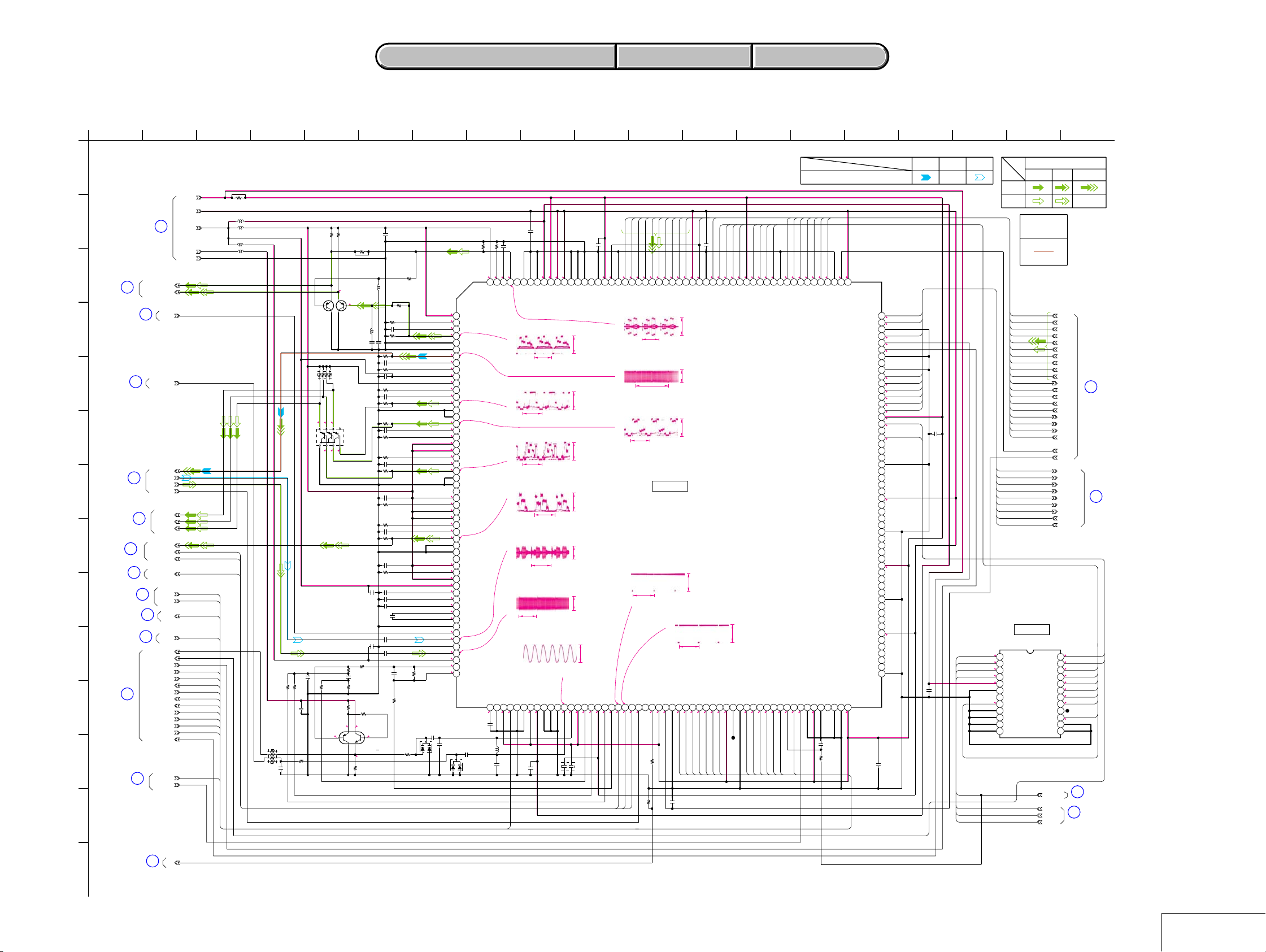
CCD-TRV128/TRV228/TRV228E/TRV328/TRV428/TRV428E
For Schematic Diagram
• Refer to page 4-43 for printed wiring board.
1
VC-341 BOARD (2/10)
A
CAMERA/VTR PROCESS,LENS CONTROL (CL BLOCK)
XX MARK:NO MOUNT
NO MARK:REC/PB MODE
R:REC MODE
P:PB MODE
B
C
D
E
16
(8/10)
(4/10)
IC_301_C_OUT
IC_301_Y_OUT
17
(8/10)
18
15
(9/10)
AFC_F0_ADJ
C_OUT
D_2.8V
D_1.5V
A_4.6V
REG_GND
A_2.8V
L303
L304
F
REC_RF
PB_C_RF
19
RF_AGC_OUT
21
(10/10)
(10/10)
(4/10)
22
G
H
I
J
27
K
(6/10)
20
(10/10)
(6/10)
DOP
PANEL_R
PANEL_G
PANEL_B
EVF_G/BW_Y
PANEL_VD
PANEL_HD
PANEL_SYNC
XVC_SCK
23
VC_SO
VC_SI
25
(6/10)
26
SYS_V
(6/10)
AFC_F0
VIVDO
XTBC_V_RST
LCD_HOLD
XCS_IC_301
MECHA_HD
JOG_VD
MECHA_VD
MECHA_FLD
ATF_SAMPLE
XSG_V_RST
X1/2_SWP
SWP_DIR
TBC_VD
XVC_SCK
LCD_HOLD
XCS_IC_301
MECHA_HD
JOG_VD
MECHA_VD
MECHA_FLD
ATF_SAMPLE
XSG_V_RST
X1/2_SWP
SWP_DIR
VC_SO
VC_SI
SYS_V
PANEL_VD
PANEL_HD
PANEL_SYNC
L
28
(6/10)
CK_CONT2
CK_CONT1
CK_CONT2
M
4-2. SCHEMATIC DIAGRAMS
4-2. SCHEMATIC DIAGRAMS
45632 17 1812 1378 1511 161410 199
R301
XX
10uHL302
10uH
10uHL301
10uH
R302
10k
RB301
10k
C303
0.1u
R338
R339
2200
XX
R0.9/P1
0.3
Q305
XX
0.8
C304
390p
1200
R303
C302
1u
R332
15k
Q306
2SA207800LS0
BUFFER
RB302
2200
Q302
HN4A71FK
(TE85R)
BUFFER
0.8
0.8
7
6
5
8
324
1
0.2
0.2
0.2
1k
R308
4.7u
C309
R306
R309
6800
470
R307
5600
3.5 4.8
6
4
R2.9
/P1.4
5
1
3
R312
XX
L305
XX
±
5%
C307
0.1u
C306
0.1u
R315
820
R311
100
UP04601008S0
R2.9/P1.5
R310
3300
C301
4.7u
R340
L306
XX
±
5%
R318
220
C312
0.1u
R3.5
/P2.1
2
Q304
VCO
XX
R313
XX
R316
12k
C311
XX
XX
0.1u
C305
C308
R319
C323
12k
R320
C313
0.1u
270
R321
R322
C314
0.1u
12kR323
R324
12k
C315
0.1u
R325
270
C316
XX
R326
XX
12k
R327
0.1u
C317
R328 270
XX
C318
R329
XX
0.1u
C319
0.1u
C320
0.1u
C321
C325
0.01u
0.01u
C310
0.01uC322
C324
0.47u
R330
39k
R314
R1.4/P1
470R317
R0.3/P0
R1.4/P0.8
5600
R1.4/P0
1u
R1.4/P0.4
270
R1.5/P0.6
R1.4/P0.2
R1.6/P0
R0.2/P0
R0.2/P0
R0.3/P0.8
R0.3/P1.4
R0.4/P1.4
R0.3/P1.4
R0.3/P1.4
R2.8/P1.4
R2.8/P1.4
R331
1M
D301
C326
1500p
KV1870RTL-G
15k
R334
220
2.811.4
216
2.8
1
VDDAA8
1
2
REXT8
3
CBU8
0.3
4
DAO8
5
VSSAA8
6
VSSAA7
7
DAO7
8
CBU7
9
REXT7
2.9
VDDAA7
10
2.8
VDDAA6
11
1.6
REXT6
12
CBU6
13
0.2
DAO6
14
VSSAA6
15
VSSAA5
16
0.2
DAO5
17
1.5
CBU5
18
1.5
REXT5
19
2.8
VDDAA5
20
2.8
VDDAA4
21
1.6
REXT4
22
CBU4
23
0.2
DAO4
24
VSSAA4
25
VSSAA3
26
DAO3
27
2.8
CBU3
28
REXT3
29
2.8
VDDAA3
30
2.8
VDDAA2
31
REXT2
32
0.4
CBU2
33
0.1
DAO2
34
VSSAA2
35
VSSAA1
36
DAO1
37
2.8
CBU1
38
0.3
REXT1
39
2.8
VDDAA1
40
2.8
VDDAA0
41
VRBAD
42
0
VRTAD
43
VINNAD
44
AD_IN
45
OP_OUT
46
VSSAA0
47
C_IN
48
ATF_IN
49
VREFOP
50
Y_RF_IN
51
2.8
AVDD
52
AMPO
53
INN
54
R0/P1.4
C329
1u
C327
XX
C328
L308
0.01u
3.3uH
D302
KV1870RTL
-G
VC-341 BOARD SIDE A VC-341 BOARD SIDE B
VC-341 BOARD SIDE A VC-341 BOARD SIDE B
AD9
AD8
AD7
AD6
AD5
AD4
AD3
AD2
R333
5600
VDDAA9
215
REXT9
C331
0.1u
0.2
212
213
214
CBU9
DAO9
8
C332
1u
2.8
2.8
207
208
209
210
211
VSSA9
PAVSSB
PDVSSB
PAVDDB
TESTDAC
PDVDDB
IC301 4 REC/PB
H
AD1
C335
1u
1.5
1.5
201
202
203
204
205
206
PAVSSC
PDVSSC
PAVDDC
PDVDDC
IN_VSS3
420 mVp-p
200
XTALOUT
XTALIN
2.8
199
IN_VDD3
R1.1/P1.4
1.5
196
197
198
PLLENB
CCDCKL
7
9
R1.2/P1.4
R1.2/P1.4
R1.2/P1.4
R1.2/P1.4
192
193
194
195
ADIN3
ADIN2
ADIN1
ADIN0
IC301 <xzc> REC/PB
H
IC301 7 REC
ADIN4
R1.3/P1.5
191
ADIN5
R1.1/P1.3
190
ADIN6
R0.7/P1.3
189
ADIN7
R0.6/P1.3
188
AD10
R0.3/P1.5
1.5
186
187
ADIN9
ADIN8
230 mVp-p
DVDD5
ADCK
XX
CLP1
DVSS11
2.700
183
CLP1
OSD_L_ON
182
OSD_L_ON
OSD_R_ON
181
OSD_R_ON
OSD_P_ON
0.1
180
OSD_P_ON
CGCK
1.4
179
COLOR1
COLOR2
COLOR4
COLOR3
2.8
2.1
2.2
2.20R2.3/P0
173
174
175
176
177
178
CGCK
COLOR1
COLOR2
COLOR3
COLOR4
IO_VDD5
C341
1.5
184
185
ADCK
390 mVp-p
q;
IC301 qf REC/PB
H
qs
IC301 wf REC/PB
470 mVp-p
460 mVp-p
NTSC: 33.3 msec
PAL: 40 msec
qa
IC301 qj REC/PB
H
470 mVp-p
H
qd
IC301 ef REC/PB
330 mVp-p
IC301
CAMERA/VTR PROCESS,ATF,
LENS CONTROL
IC301
HG76C012FL
H
qf
IC301 rl PB
150 mVp-p
qj
R2.9/P1.4
2.8
R2.5/P1.4
PANEL_VD
IC301 uf REC/PB
V
2.6
0.201.4
R336
10k
PANEL_SYNC
PANEL_HD
1k
R335
qk
2.8
1.3
2.8 Vp-p
IC301 ug REC/PB
H
0
1.4
2.8
R0/P0.6
R1.6/P1.3
JOG_VD
X1/2_SWP
ATF_SAMPLE
SWP_DIR
XSG_V_RST
C336
XX
2.5
SYS_V
1.4
MECHA_FLD
2.8 Vp-p
0
2.8
2.5
2.6
0.7
2.2
R2.8/P0.2
CL301
XVC_SCK
VC_SO
VC_SI
MECHA_HD
MECHA_VD
XCS_IC_301
H
qg
IC301 ta PB
380 mVp-p
NTSC: 33.3 msec
PAL: 40 msec
qh
IC301 yh PB
1.7 Vp-p
NTSC: 14.318 MHz
PAL: 14.187 MHz
INP
AVSS56SCAN_PATH57WRHLD58MUTE59DVSS160PDVDDA61PAVDDA62PAVSSA63PDVSSA64IN_VSS165OSCO66OSCI67IN_VDD168AFCC69PDET170DVDD171PDET272PDET373PANELVD74PANELHD75PANELSYNC76DOP77TRAPCONT78OFSC79OUT_VDD180MCK81DVSS282JVDI83HSWP84SWP85XSGRST86ATSMPL87SYSV88MECHAFLD89IN_VDD290BCK91IN_VSS292CSYNC93MECHAVD94XSCK95SO96SI97XCS98XRST99MCKCONT
55
2.8
2.8
LCD_HOLD
2.8
R2.8/P0
C330
XX
0.1u
C333
2.801.5
R2.8/P1.3
R2.8/P1.3
R2.9/P1.4
4
C334
0.1u
6.3V
123
DVSS10
PBLK
172
2.7
PBLK
ID
R1.4/P0
100
0
CK_CONT2
SIGNAL PATH
Ref.signal
XV1
AVD
AHD
R2.7/P0
R2.5/P2.8
R0.1/P0
168
169
170ID171
AVD
AHD
ADCKCONT
FECKIN
101
102
103
2.8
R2.8/P0
XV1
XFEON
167
104
V_STOP
R0.1/P0
R2.8/P0
166
VGAT
RAMTEST
105
R341
C337
XSG1
XX
1k
165
XSG1
FECKOUT
106
DVSS9
DVSS3
REC/PB
PB
REC
CHROMA
VIDEO SIGNAL
Y
Y/CHROMA
REC
PB
VIDEO/SERVO
SIGNAL
1.5
1.5
163
164
VCK
DVDD4
IRIS_COM
EN1
DIR1B
DIR1A
EN0
DIR0B
DIR0A
ZM_RST
FC_RST
1.5
123456789101112
2.7
2.7
2.8
2.8
1.4
AD1
AD2
AD3
AD4
AD5
AD6
AD7
AD8
AD9
AD10
V_STOP
PBLK
ID
XSG1
XV1
AVD
AHD
CLP1
ADCK
IC302
CHARACTER GENERATOR
IC302
BU3097-04FV-E2
SCLK
CSB
SDATA
RESETB
VDD
SDDIR
NC
OSCIN
TEST MONI
VSS
TM0
TM1
HSYNC
VSYNC
XRST_VTR
XCS_OSD
XOSD_SCK
OSD_SO
AD1
AD2
AD3
AD4
AD5
AD6
AD7
AD8
AD9
AD10
V_STOP
11
PBLK
(1/10)
ID
XSG1
XV1
AVD
AHD
CLP1
ADCK
CL
MCK
IRIS_COM
EN1
DIR1B
DIR1A
30
EN0
DIR0B
(3/10)
DIR0A
ZM_RST
FC_RST
2.6
VIHD
VIVDO
2.8
0
COLOR1
VC0
2.2
COLOR2
VC1
COLOR3
2.1
VC2
OSD_P_ON
0.1
BLKA
2.1
COLOR4
VC3
0
OSD_R_ON
BLKB
CL302
OSD_L_ON
BLKC
0
TM3
TM2
13 14 15 16 17 18 19 20 21 22 23 24
31
(6/10)
32
(6/10)
SENS1
SENS0
TEST
IRIS
TBCVD
XTECVRST
TESTBS
VCKO
DVSS8
EN1
DIR1B
DIR1A
DIR0A
DIR0B
EN0
IO_VDD4
VIHDO
MEMHDI
VIVDO
MEMVDI
VIFLDO
MEMFLDI
DVSS7
YMO0
YMI0
YMO1
YMI1
DVDD3
YMO2
YMI2
YMO3
YMI3
DVSS6
YMO4
YMI4
YMO5
YMI5
IO_VDD3
YMO6
YMI6
YMO7
YMI7
DVSS5
CMO3
CMI3
CMO2
CMI2
DVDD2
CMO1
CMI1
CMO0
CMI0
EOR_OUT
TESTKP
DVSS4
IO_VDD2
107
108
2.8
ZM_RST
162
2.8
FC_RST
161
2.8
160
IRIS_COM
159
R1.4/P0
158
2.8
157
R0/P2.8
156
155
154
EN1
153
DIR1B
0
152
DIR1A
R2.4/P0
151
DIR0A
R2.4/P0
150
DIR0B
R2.2/P0
149
EN0
R0.3/P0
148
R2.8/P0
147
2.8
VIHD
146
2.6
145
144
2.8
143
142
141
140
139
138
137
136
135
1.5
134
133
132
131
130
129
128
127
126
125
2.8
124
123
122
121
120
119
118
117
116
115
1.5
114
113
112
111
110
109
C338
XX
C339
0.1u
VIVDO
XOSD_SCK
XCS_OSD
OSD_SO
XX
C340
VIVDO
XRST_VTR
XRST_VTR
XCS_OSD
XOSD_SCK
OSD_SO
CGCK
29
FSC
N
05
(8/10)
4-11 4-12
VC-341 (2/10)
Page 31

CCD-TRV128/TRV228/TRV228E/TRV328/TRV428/TRV428E
4-2. SCHEMATIC DIAGRAMS
4-2. SCHEMATIC DIAGRAMS
For Schematic Diagram
• Refer to page 4-43 for printed wiring board.
1
2 10
VC-341 BOARD (3/10)
A
LENS DRIVE (LD BLOCK)
XX MARK:NO MOUNT
NO MARK:REC/PB MODE
R:REC MODE
P:PB MODE
B
C
D
24P
E
F
LENS BLOCK
G
H
•
LENS BLOCK is replaced as block,
so that there PRINTED WIRING BOARD and
SCHEMATIC DIAGRAM are omitted.
CN201
IRIS_DRIVE(+)
IRIS_HALL(+)
IRIS_BIAS(+)
IRIS_HALL(-)
IRIS_BIAS(-)
IRIS_DRIVE(-)
ZM_SENSE_VCC
ZM_SENSE_OUT
LENS_DET
FC_SENSE_VCC
FC_SENSE_OUT
ZOOM_A
ZOOM_B
ZOOM_XB
ZOOM_XA
IR_SWITCH
IR_SWITCH
FOCUS_A
FOCUS_B
FOCUS_XB
FOCUS_XA
TEMP
TEMP
24
23
22
21
20
19
18
17
16
15
14
13
12
GND
11
10
9
8
7
6
5
4
3
2
1
VC-341 BOARD SIDE A VC-341 BOARD SIDE B
VC-341 BOARD SIDE A VC-341 BOARD SIDE B
4 118
C202
0.01u
C219
XX
R218
XX
D203
XX
56 12
2200
R210
R211
R212
470k
0.9
0.9
4
5
6
7
IN2-
IN2+
OUT2
OUT39IN3-10IN3+11GND12IN4+13IN4-14OUT4
8
/P0
R1.4/P0.2
R1.4/P0.1
470kR209
L201
D202
1SS355TE-17
Q201
RN1119FV(TH3SONY)
IRIS DRIVE
R1.9/P2.8
RB203
47k
Q202
UP04116008S0
SENSOR SWITCH
C203
4700p
C209
0.22u
R208
IC202
470k
C207
470p
R1.4/P0.2
R0.9
C206
0.1u
R207
220k
R206
10k
R203
10
IC202
IRIS DRIVE
HALL BIAS CONTROL
HALL GAIN CONTROL
HALL AMP
LM224PT
R1
/P0
R205
2200
C204
R204
1M
4.7u
1
2.8
2
6
3
C205
0.1u
2.8
4
2.8
5
R0.9/P0R0.8/P0
6800
Vcc
R213
RB202
937
HALL_REF
RB201
1k
R215
C216
10k
C215
2200p
XX
L202
10uH
C217
C218
4.7u
0.1u
R216
47k
R217
XX
C211
0.001u
4.8
0.9
0.9
1.2
1
2
3
IN1-
IN1+
OUT1
0.7
0.1
0.1
0.1
2SC5658T2LQ/R
HALL GAIN
330
CONTROL
C212
0.47u
22k
10uH
C213
XX
R214
1k
0.6
Q203
C214
0.01u
HALL_OFFSET
HALL_GAIN
A_4.6V
D_2.8V
REG_GND
REG_GND
MT_5V
IRIS_PWM
FC_RST_LED
ZM_RST_LED
LENS_DET
XNS_SW
HALL_AD
LENS_TEMP_AD
(MT_GND)
33
(4/10)
34
(9/10)
35
(6/10)
VC-341 (3/10)
2.8
R3.1/P0.2
0.250.2
I
IC201
FOCUS/ZOOM
MOTOR DRIVE
IC201
UPD16877MA-6A5-E2
J
24
VDD
PGND
OUT2B
OUT1B
VM!2OUT 1A3PGND4OUT2A5OUT3A6PGND7OUT4A8VM49IN110EN111IN212EN2
1
5
0.3
R0.8/P0.2
VM23
EN4
PGND
OUT4B
OUT3B
5
0.3
0.3
0.20R0/P2.80R2.4
16
17
18
19
20
21
22
23
13
14
15
IN3
IN4
EN3
R1.5/P2.80R0.2/P2.8
/P2.8
C208
0.01u
C210
47u
6.3V
0
K
05
4-13 4-14
IRIS_COM
ZM_RST
FC_RST
DIR1B
DIR1A
EN1
EN0
DIR0A
DIR0B
30
(2/10)
Page 32

CCD-TRV128/TRV228/TRV228E/TRV328/TRV428/TRV428E
For Schematic Diagram
• Refer to page 4-43 for printed wiring board.
1
2
VC-341 BOARD (4/10)
A
REC/PB AMP (RF BLOCK,ER BLOCK)
XX MARK:NO MOUNT
NO MARK:REC/PB MODE
R:REC MODE
P:PB MODE
B
C
M2100/M2101
MECHANISM
D
E
F
G
H
DECK(1/2)
TRV128/TRV228/TRV328/TRV428
M2100:
TRV228E/TRV428E
M2101:
FLYNG
ERASE
CH
SP1
CH
SP2
VIDEO HEAD
CN481
ql
IC481 wj,ef> PB
11P
NTSC: 33.3 msec
GND
GND
GND
SP1Y
SP1X
GND
SP2X
SP2Y
GND
FE(Y)
FE(X)
PAL: 40 msec
1
2
3
4
5
6
7
8
9
10
11
ET481
ET482
6.1 Vp-p
4-2. SCHEMATIC DIAGRAMS
4-2. SCHEMATIC DIAGRAMS
43
ws
IC481 6 REC
NTSC: 33.3 msec
PAL: 40 msec
L483
C493
XX
XX
L481
220uH
C482
C481
33u
0.01u
6.3V
R487
C483
0.01u
27k
0.01u
FB481
C486
C487
C484
R481
56:
39:
R481
0
R482
560
0.01uC488
0.022u
0.022u
FB482
R484
27k
TRV128/TRV228
/TRV328/TRV428
TRV228E/TRV428E
R4.3/P4.7
2SA1965-S-TL
R488
R489
C485
XX
R483
R4.1/P4.7
Q481
0.1u
R0.9/P0
REC DUMP1
25
GND
26
4.6
REC1 OUT
27
0.7
PB1 IN
28
4.6
VCC AMP
29
220
2.6
PB DUMP1
30
220
2.6
PB DUMP2
31
1.1
BIASADJ
32
0.01uC489
0.7
PB2 IN
33
4.6
REC2 OUT
34
GND
35
R0.9/P0
REC DUMP2
36
C494
0.1u
RB483
4.7
100
2SA207800LS0
R4.3/P4.7
Q481-483
ERASE HEAD OSC
22uH
4.7u
C498
C496
R493
0.01u
2700
R0.5/P0.3
R2.5/P0.1
23
24
REC1 IN
RAMP V1
RAMP V238REC2 IN39VSSW2 OUT40GND41PCM IN42RAMP CONT43RAMP44PCM REC45AFREC46BOTH_REC/DV PBPS
37
R2.5/P0.1
R494
2700
C497
0.01u
2200
4.7
Q482
22
VPSW1 OUT
R3.1/P4.4
0.5
R3.8/P4.7
400 mVp-p
0.5%
±
150k
R495
2.3
20
21
VCC
4.7
RAMP IR
IC481
REC/PB AMP
CXA3265R-T4
R3.1/P4.7
R490
270
R491
220
UP04601008S0
7
wa
IC481 9 PB
C504
XX
XX
XX
XX
C501
C502
C499
0.6
0.4
2.2
R0.1/P1.9
R0/P2.8
14
15
16
17
18
19
IC481
MTIN
MT_Q
C490
100p
C491
150p
Q483
CARDET
PCMOUT/MTSW
5
13
MT_F0
PBRFOUT
YLPFOUT/CARDETOUT
REC_Y/MT_CONT
SWP48REC_L_CONT
47
0
1.4
L482
12uH
C492
82p
R2/P4.7R3.6/P4.7
6
4
1
3
R1.2/P2.8
RP_PB
2
RF AGCOUT
Y/C/ATF IN
3.3
R492
R1.4
/P2.4
DOC_DET
CLPFOUT
AGC TC
RP_IR
Y MIX
AFM IN
RB481
DOP
VCC3
22k
33k
VC-341 BOARD SIDE A VC-341 BOARD SIDE B
VC-341 BOARD SIDE A VC-341 BOARD SIDE B
NTSC: 33.3 msec
PAL: 40 msec
2.5
12
R0/P1.3
11
R4.5/P3.5
10
R1.5/P2
9
R2.2/P2.4
8
0
7
2.2
6
0
5
2.6
4
R3.6/P0.8
3
4.7
2
0
1
C505
0.01u
16V
L484
220uH
C503
XX
C500
0.1u
C495
100p
400 mVp-p
RB482
470k
C507
0.001u
10 14
w;
IC481 qa PB
H
C513
0.47u
0
0
Q484
UNR32A300LS0
AGC SLOW
C509
4700p
C508
C514
0.01u
C515
0.01u
C510
XX
C511
XX
0.01u
1165
150 mVp-p
R4.5/P3.5 3.9
Q485
UNR31A500LS0
SWITCH
4.7
12
SIGNAL PATH
Ref.signal
1.5M_DEV
AU_BPF
A_FADE
1389
VIDEO SIGNAL
CHROMA Y/CHROMA
REC
PB
AGC_SLOW
RP_PB_MODE
DOP
BOTH_REC
XFE_ON
RF_SWP
DOP
REC_RF
PB_C_RF
RF_AGC_OUT
PB_C_RF
1.5M_DEV
AU_BPF
A_FADE
PB_RF
REC_AFM
PB_RF
REC_2
15 16
AUDIO
Y
SIGNAL
VIDEO/AUDIO/
SERVO
SIGNAL
REC/PBREC PB
VIDEO/SERVO
SIGNAL
37
(6/10)
19
(2/10)
13
(1/10)
38
(8/10)
39
(10/10)
I
VC_SO
IC251
EVR
(D/A CONVERTER)
IC251
J
(9/10)
K
05
RP_4.6V
A_4.6V
36 18
AU_2.8V
REG_GND
FB252
FB251
0uH
C252
4.7u
0uH
1.5M_DEV
AU_BPF
A_FADE
C251
1u
4.8 2.5
4.8
R3.6/P0.8
3.3
2.2
4.7
4.7
0.8
2
0
2.9
BH2222FV-E2
12345678
A_4.9V(VCC)
A_4.9V(VDD2)
REC_Y/MT_CONT
RF_AGC_CONTREC_L_CONT
MT_F0
XMP/ME
CFG_DUTY
91011121314
1.5M_DEV
AU_BPF
BEEP_EVR HALL_GAIN
A_FADE
D_3.2V(VDD1)
GND
AFC_F0_ADJXRF_AGC_OFF
HALL_OFFSET
DOC_DET
RP_IR
FRQ_TUNE
REC_BIAS
HALL_REF
SWP(SEL)
STB(LD)
MT_Q
CLK
DI
XVC_SCK
0.5
VC_SO
2.4
3.9
2.3
AFC_F0_ADJ
2.1
FRQ_TUNE
2.5
1.1
21 22 23 24 25 26 27 28
0.5
HALL_REF
0.9
0.8
HALL_GAIN
1.2
HALL_OFFSET
1.4
DA_STRB
0
15 16 17 18 19 20
XVC_SCK
DA_STRB
HALL_GAIN
HALL_OFFSET
HALL_REF
FRQ_TUNE
AFC_F0_ADJ
4-15 4-16
VC_SO
XVC_SCK
DA_STRB
HALL_GAIN
HALL_OFFSET
HALL_REF
FRQ_TUNE
AFC_F0_ADJ
40
(6/10)
42
(6/10)
33
(3/10)
2
(1/10)
(2/10)
VC-341 (4/10)
Page 33

CCD-TRV128/TRV228/TRV228E/TRV328/TRV428/TRV428E
For Schematic Diagram
• Refer to page 4-43 for printed wiring board.
1
VC-341 BOARD (5/10)
A
SERVO (SB BLOCK)
XX MARK:NO MOUNT
NO MARK:REC/PB MODE
R:REC MODE
P:PB MODE
∗:IMPOSSIBLE TO MEASURE THE
VOLTAGE AT THE MARKED POINTS.
B
43
(6/10)
C
M2100
/M2101
MECHANISM
DECK (2/2)
D
E
F
M2101:
/TRV228
/TRV328
/TRV428
TRV228E
/TRV428E
M903
LOADING
MOTOR
MOTOR
DRUM
M
CN401
CN402
FP/PG
M901
CN403
TRV128
M2100:
G
MECHANISM
BLOCK
H
(CAPSTAN MOTOR)
(PAGE 4-33)
I
J
K
MECHANISM
BLOCK
(SENSOR)
(PAGE 4-33)
L
05
2P
10P
22P
C_LOCK_SW
SENSOR_VCC
TAPE_LED(A)
TAPE_LED(K)
TEPE_END(C)
TAPE_TOP(C)
CAP_V
CAP_V
CAP_W
CAP_W
CAP_U
CAP_U
REG_GND
FG VCC
M-SW(C)
M-SW(B)
M-SW(A)
CN404
HI8_MP
REC_PROOF
ME/MP
HALL_COM
T_REEL(-)
T_REEL(+)
S_REEL(+)
S_REEL(-)
REG_GND
LM(+)
LM(-)
(7/10)
HW2
HW1
HV2
HV1
HU2
HU1
VH+
FG2
FG1
DEW
44
1
2
1PG
2FG-PG_COM
3FG
4COM
5W
6W
7V
8V
9U
10U
VH-
1
2
3
4
5
6
7
8
9
10
11
12
13
14
15
16
17
18
19
20
21
22
15P
15
14
13
12
11
10
9
8
7
6
5
4
3
2
1
3
MODE_SW_A
MODE_SW_B
MODE_SW_C
DEW_AD
HI8_MP_SW
REC_PROOF
ME_SW
XCC_DOWN
C402
XX
C401
0.1u
C403
XX
DRUM_PG_SENS
FG_PG_COM
DRUM_FG_SENS
DRUM_COM
MODE_SW_C
MODE_SW_B
MODE_SW_A
XCC_DOWN
HI8_MP_SW
REC_PROOF
T_REEL_+
R403
470
S_REEL_+
S_REEL_-
TAPE_END_C
TAPE_TOP_C
MODE_SW_A
MODE_SW_B
MODE_SW_C
DEW_AD
R402
330k
R401
47k
HI8_MP_SW
REC_PROOF
ME_SW
XCC_DOWN
LM_-
LM_+
DRUM_W
DRUM_V
DRUM_U
WHE-
WHE+
VHE-
VHE+
UHE-
UHE+
HE_VCC
CAP_V
CAP_W
CAP_U
FG2
MR_VCC
FG1
DEW_AD
ME_SW
T_REEL_-
5
52
(9/10)
CAP_W
CAP_V
CAP_U
CAP_ON
CAP_FWD
MR_VCC
CAP_FG
FG1
FG2
UHE+
UHE-
VHE+
VHE-
WHE+
WHE-
HE_VCC
TAPE_TOP
TAPE_TOP_C
TAPE_END_C
TAPE_END
S_REEL_+
S_REEL_-
SREEL_FG
T_REEL_+
T_REEL_-
TREEL_FG
Q401
UNR32A600LS0
LED DRIVE
4-2. SCHEMATIC DIAGRAMS
4-2. SCHEMATIC DIAGRAMS
REG_GND
4.4
EP_13.5V
REG_GND
D_2.8V
(MT_GND)
VTR_UNREG
MT_5V
DRUM_VS
CAP_VS
0
6
C404
0.1u
R406
XX
R404
270
R409
82
C406
C405
0.1u
XX
7892
C407
0.001u
50V
C410
1u
16V
C408
0.01u
DRUM_FG
DRUM_PG
TAPE_TOP
TAPE_END
SREEL_FG
TREEL_FG
CAP_FWD
CAP_FG
CAP_ON
R405
0
FB401
C409
0.047u
VC-341 BOARD SIDE A VC-341 BOARD SIDE B
VC-341 BOARD SIDE A VC-341 BOARD SIDE B
10 11
C420
C415
C413
R428
XX
0.1u
XXR429
XXR407
XXR408
C417
0.1u
0.1u
0.1u
R411
2.2
R410
R412
2.2
2.2
C424
1u
C439
C425
0.1u
C432
0.1u
12 17
0.1u
C436
0.1u
13 14
wf
IC401 yd,yg,yk REC/PB
154
LM_-
LM_+
DRUM_W
DRUM_V
DRUM_U
16
1.4 Vp-p
2.8
78
79
RB401
10k
2.8
1
2
2.8
3
1.4
4
5
6
1.4
7
R0/P1.4
8
0.4
9
0.6
10
0.6
11
0.4
12
0.4
13
0.2
14
0.2
15
2.8
16
0.7
17
1.3
18
2.8
19
1.3
20
10V
DRUM_FG
DRUM_PG
TAPE_TOP
TAPE_END
SREEL_FG
TREEL_FG
CAP_FWD
CAP_FG
CAP_ON
XREEL_HALL_ON
TAPE_LED_ON
CAP_FG
80
NC
C_W
CAPON
C_FRC
wd
TEST
VMR
CFGOUT
C_PGND
GND
CFGIN+
CFGIN-
CAGC
U+
U-
V+
V-
W+
W-
VCC1
VH
TOPIN
TOPOUT
ENDIN
C411
0.01u
C412
0.01u
IC401 4 REC/PB
ENDOUT22RLP123RLM124RLO125RLDO126RLP227RLM228RLO229RLDO230VCC231LIMOUT32DEC133DEC234XRESET35MCK36SCK37XCS38SI39DGND40CSR
21
∗∗
2.8
1.9
1.9
XX
XX
C416
C414
45
(6/10)
91
(10/10)
74
75
76
77
C_V
C_VS
C_VS
NTSC: 820 Hz
PAL: 1148 Hz
wh
1.9
1.9
XX
XX
C421
C419
C418
0.510.510.5
0
69
70
71NC72
73
C_U
L_VM
L_OUT2
L_PGND
2.8 Vp-p
IC401
DRUM/CAPSTAN/LOADING
MOTOR DRIVE
IC401
TB6550FG(O,EB)
IC401 t; REC/PB
NTSC: 33.3 msec
PAL: 40 msec
8.3
0.2
C423
0.1u
XX
XX
C422
SIGNAL PATH
Drum speed servo
L_OUT1
00
68
D_W
1.5
63
64
65
66NC67
D_V
D_VS
D_VS
2.8 Vp-p
2.8
1.5
2.5
2.8
0.5
C446
XX
wj
IC401 rf REC/PB
13 sec
0.8
61
NC62NC
D_U
D_PGND
COM
WIN
VIN
UIN
DFILTER
DFC
DFGOUT
DFGIN
VREF
PGOUT
PGIN
PGC
VG
ISNF
DBOUT
DBIN
CBLOUT
CBOUT
CBIN
0.5
C426
0.01u
C434
C437
0.001u
0.001u
60
0.8
59
0.8
C433
58
57
56
55
54
53
52
51
50
49
48
47
46
45
44
43
42
41
0.001u
0.8
0.8
0.8
2.1
1.4
1.3
1.3
0.1
1.3
0.9
13.6
0.1
0.6
0.6
0.3
0.3
0.3
XXR430
1uC429
TRV228E/TRV428E
wk
IC401 ra REC/PB
80 mVp-p
NTSC: 180 Hz
PAL: 150 Hz
wg
IC401 td REC/PB
NTSC: 180 Hz
PAL: 150 Hz
C431
0.047u
C435
2.2u
R416
XX
0.022uC430
C427
4700p
C442
470p
R426
15k
70 mVp-p
R424
C441
10k
R431
0
1u
R413
2.8 Vp-p
C443
0.1u
C428
0.022u
TRV228E/TRV428E
R427
R414
0
10k
15k
47k
DRUM_COM
DRUM_FG
DRUM_FG_SENS
FG_PG_COM
DRUM_PG
DRUM_PG_SENS
R425
XX
R418
XX
R423
XX
C440
XX
C445
0.01u
C444
0.01u
R413,R427
:TRV128/TRV228/TRV328/TRV428
:TRV228E/TRV428E
R414
:TRV128/TRV228/TRV328/TRV428
:TRV228E/TRV428E
DRUM_ERROR
CAP_ERROR
CL
UNLOAD
LOAD
XCS_IC-401
DRUM_PWM
CAP_PWM
VC_SO
XVC_SCK
46
(9/10)
12
(1/10)
47
(6/10)
48
(6/10)
13 sec
XRST_VTR
LM_LIM_DET
REC/PBREC
PB
50
(6/10)
51
(6/10)
0.8
0.8
1.5
0.2
0.2
Drum phase servo
Drum servo(speed and phase)
Capstan speed servo
Capstan servo(speed and phase)
VC-341 (5/10)
4-17 4-18
Page 34

CCD-TRV128/TRV228/TRV228E/TRV328/TRV428/TRV428E
For Schematic Diagram
• Refer to page 4-43 for printed wiring board.
1
VC-341 BOARD (6/10)
A
CAMERA/MECHA CONTROL
XX MARK:NO MOUNT
35
53
(10/10)
(10/10)
45
(5/10)
(3/10)
CUSTOM_LED_ON
DCOUT_JACK_IN
54
55
(8/10)
47
(5/10)
51
(5/10)
XREEL_HALL_ON
B
C
D
E
F
G
43
(5/10)
(10/10)
H
56
(10/10)
57
(7/10)
58
I
4
(1/10)89(9/10)
(9/10)
59
J
8
K
L
M
N
05
60
31 50
(5/10)(2/10)(1/10)
(2/10)26(7/10)
61
(7/10)
62
(7/10)
93
(10/10)
(10/10)
64
(10/10)
(10/10)
(10/10)
75
63
MD2 ( )
65
XNS_SW
ZM_RST_LED
FC_RST_LED
IRIS_PWM
LENS_TEMP_AD
HALL_AD
LENS_DET
EVF_DD_ON
AV_JACK_IN
XS_JACK_IN
VST_C_RESET
PITCH_AD
YAW_AD
UNLOAD
XCS_IC_401
DRUM_PWM
CAP_PWM
LM_LIM_DET
TREEL_FG
SREEL_FG
TAPE_TOP
TAPE_END
DRUM_FG
DRUM_PG
TAPE_LED_ON
CAP_FWD
CAP_FG
CAP_ON
MODE_SW_A
MODE_SW_B
MODE_SW_C
HI8_MP_SW
REC_PROOF
DEW_AD
V_LIGHT_PWM
ZOOM_VR_AD
CAM_DD_ON
DCOUT_ON
XCS_LCD
XRST_VTR
IC_701_SCK
XCS_IC_701
IC_701_SI
IC_701_SO
XSYS_RST
REC_CRRT0
REC_CRRT1
EEP_SO
EEP_SCK
REG_GND
XCS_MC_FLASH
XCS_EEP
SWP_DIR
BEEP
LOAD
ME_SW
OSD_V
SYS_V
EEP_SI
3 18
XNS_SW
ZM_RST_LED
FC_RST_LED
IRIS_PWM
LENS_TEMP_AD
HALL_AD
LENS_DET
EVF_DD_ON
AV_JACK_IN
XS_JACK_IN
CUSTOM_LED_ON
DCOUT_JACK_IN
VST_C_RESET
PITCH_AD
YAW_AD
BEEP
UNLOAD
LOAD
XCS_IC_401
DRUM_PWM
CAP_PWM
LM_LIM_DET
TREEL_FG
SREEL_FG
TAPE_TOP
TAPE_END
DRUM_FG
DRUM_PG
XREEL_HALL_ON
TAPE_LED_ON
CAP_FWD
CAP_FG
CAP_ON
MODE_SW_A
MODE_SW_B
MODE_SW_C
ME_SW
HI8_MP_SW
REC_PROOF
DEW_AD
V_LIGHT_PWM
ZOOM_VR_AD
OSD_V
CAM_DD_ON
DCOUT_ON
XCS_LCD
XRST_VTR
SYS_V
IC_701_SCK
XCS_IC_701
IC_701_SI
IC_701_SO
XSYS_RST
REC_CRRT0
REC_CRRT1
EEP_SI
EEP_SO
EEP_SCK
XCS_MC_FLASH
XCS_EEP
SWP_DIR
XSYS_RST
DOP
AGC_SLOW
LM_LIM_DET
XCS_IC_401
UNLOAD
LOAD
TAPE_TOP
TAPE_END
EVF_DD_ON
LENS_DET
DA_STRB
ZM_RST_LED
FC_RST_LED
CUSTOM_LED_ON
VST_C_RESET
5
NO MARK:REC/PB MODE
R:REC MODE
P:PB MODE
∗
:IMPOSSIBLE TO MEASURE THE
VOLTAGE AT THE MARKED POINTS.
C602
10p
R606
XX
X601
10pC603
R605
XX
R601
100
10kR602
C601
0.01u
16V
0.1u
C605
C604
0.1u
C606
0.1u
C620
0.1u
RB602
100k
RB603
100k
RB601
100k
20MHz
4-2. SCHEMATIC DIAGRAMS
4-2. SCHEMATIC DIAGRAMS
6
HI8_MP_SW
XREEL_HALL_ON
C607
0.1u
1.4
2.8
215216
VDD
1.2
X1
1
VSS
2
∗
X0
3
XIN
4
MD2
5
MD1
6
MD0
7
2.8
XINIT
8
2.8
XRST
9
0
DOP
10
0
AGC_SLOW
11
12
13
2.8
VDD
14
0.2
LM_LIM_DET
15
2.8
XCS_IC_401
16
0
LM-
17
0
LM+
18
2.8
TAPE_TOP
19
2.8
TAPE_END
20
VSS
21
22
23
LM_LIM_CONT
24
F_RATE
25
0
EVF_DD_ON
26
XCS_EVF
27
XEVF_TALLY
28
V_OUT_ON
29
30
31
32
33
VSS
34
0
C1
35
1.5
VDD
36
37
38
39
40
41
42
43
0
LENS_DETE
44
45
0
DA_STRB
46
47
48
2.8
ZM_RST_LED
49
2.8
FC_RST_LED
50
51
0
EASY_MODE_LED
52
2.8
VDD
53
0
VST_C_CHARGE
54
HI8_MP_SW
XREEL_HALL_ON
(D_2.8V)
wl
IC601 1 (X601) REC/PB
(D_2.8V)
(D_1.5V)
(D_2.8V)
XCS_AFM_ST
57 58 59 60 61 62 63 64 65 66 67 68 69 70
55 56
7892
DOP
ME_SW
REC_PROOF
2.8
REC_PROOF
MODE_SW_C
ME_SW
MODE_SW_B
MODE_SW_C
MODE_SW_A
00000
MODE_SW_A
MODE_SW_B
TBC_VD
MECHA_VD
TAPE_LED_ON
100k
R636
CL614
R0/P2.8
2.8
2.8
2.6
IC_701_V
EXI_TEST
MEM_VD
TBC_VD
MECHA_VD
DOP
000
201202203204205206207208209210211212213214
TAPE_LED_ON
MELODY_CARR
VSS
BEEP
VIVDO
OSD_V
1.9 Vp-p
20 MHz
VSS
APOLLO_PWCTRL
xRST_VTR
xCS_AFM
IC_701_XSCK
XCS_IC_701
IC_701_SI
XCS_AU
2.9
2.8
XCS_IC_701
IC_701_SCK
2.5
IC_701_SI
IC_701_SO
2.8
IC_701_SO
XCS_APOLLO
2.8 2.8
XRST_VTR
GCAM_XSCK
71 72 73 74 75 76 77 78 79 80 81 82 83 84 85
02.8
CH_SCK
SDC_ON
XCS_GCAM
CS_CH
DRUM_PG
0.1
DRUM_PG
GCAM_SO
2.8
CH_SO
DRUM_FG
1.3
2.8
CL602
DRUM_FG
XVC_SCK
SCK_VC
IR_ON
0
XCS_IC_301
2.5
2.2
XCS_IC_301
VC_SO
CAP_FG
C610
0.1u
1.4
1.5
VDD
IR_ON
TREEL_FG
SREEL_FG
(D_1.9V)
IC601
CAMERA/MECHA CONTROL
IC601
MB91194APFF-G-153-BNDE1
(D_1.9V)
VC_SO
VC_SI
VDD
OSD_SCK
0.7
2.6
1.5
1.5
VC_SI
XOSD_SCK
XCS_OSD
CL618
CAP_FG
XCS_OSD
2.7
OSD_SO
OSD_SO
2.7
XS_JACK_IN
2.8
186187188189190191192193194195196197198199200
HP_JACK_IN
EEP_SCK (MC_FLASH_SCK)
2.8
EEP_SCK
XCS_EEP
VC-341 BOARD SIDE A VC-341 BOARD SIDE B
VC-341 BOARD SIDE A VC-341 BOARD SIDE B
10 11
SYS_V
AV_JACK_IN
RB605
1k
2.5
2.8
VSS
MIC_IN
V_JACK_IN
XS_JACK_IN
XMIC_MONO
XCS_EEP
EEP_SO (MC_FLASH_SO)
EEP_SI (MC_FLASH_SI)
DRUM_PWM
CAP_PWM
86 87 88 89 90 91 92 93 94 95 96 97 98 99
2.800.9
2.8
0.5
SYS_V
RB606
R0/P2.8
V_LIGHT_PWM
00
10k
XTBC_V_RST
CL604
1.4
TBC_V_RESET
VSS
REC_CRRT1
CL605
INTVD
e;
IRIS_PWM
REC_CRRT0
XCS_MC_FLASH
CL606
2.8
00
REC_CRRT0
REC_CRRT1
IC601 <zb,> REC/PB
NTSC: 33.3 msec
CK_CONT1
CK_CONT2
IRIS_COM_PWM
R2.8/P0
R0/P2.8
RB612
XCS_MC_FLASH
PAL: 40 msec
47k
12 17
0.1uC624
XFE_ON
CAP_FWD
BOTH_REC
MECHA_HD
RP_PB_MODE
RB613
4700
2.8
2.80R0.3/P0
R0/P2.8
R1.8/P2.8
R2.8/P0.2
172173174175176177178179180181182183184185
VDD
XFE_ON
MECHA_HD
MELODY_ENV
BOTHREC
RP_PB_MODE
(D_2.8V)
(D_1.9V)
2.9 Vp-p
(D_2.8V)
(D_2.8V)
(D_2.8V)
(D_2.8V)
(D_2.8V)
(D_2.8V)
(D_2.8V)
(D_2.8V)
ATF_DEBUG_PWM1
ATF_DEBUG_PWM2
VSS
OSC1
VDD
OSC0
100101 102 103104 105 106107 108
CL610
CL611
C611
0.1u
CAP_ON
LCD_HOLD
2.8
163164165166167168169170171
CAP_ON
CAP_FWD
LCD_HOLD
CAM_DD_ON
X1/2_SWP(HSWP)
ATF_SAMPLE
XSG_V_RST
DRUM_START
XDRUM_BRAKE
SYSTEM_AD
GRNERAL_AD
MECHA_FLD
ZOOM_SW_AD
(XUSB_EN)
IRIS_HALL_AD
LENS_TEMP_AD
SREEL_FG_AD
TREEL_FG_AD
CK_NISHIKI
DCOUT_ON
DCOUT_JACK_IN
XNS_ON_SW
ATF_DEBUG_IN/EVF_VG_AD
ATF_DEBUG_IN2
CL617
CL612
C609
0.1u
13 14
R2.8/P0
162
161
1.5
160
VDD
1.5
159
RF_SWP
1.4
158
SWP_DIR
1.6
157
R0/P0.6
156
0
155
JOG_VD
2.8
154
153
152
2.8
151
VDD
R0/P2.6
150
C2
149
VSS
148
TUL
2.8
147
AVDD_U
2.8
146
AVRH_U
145
AVSS_U
144
ANIN1
143
ANIN0
142
141
140
139
138
DRUM_ON
137
136
0
135
1.4
134
1.5
133
2.8
R616
132
XCS_IO
YAW_AD
PITCH_AD
AVSS_1
AVRH_1
AVDD_0
AVRH_0
AVSS_0
DEW_DET
AFC_F0_IN
USB_DET
XUSB_ON
XCS_LCD
AVDD1
HITEST
1k
131
1.3
130
1.2
129
R1.4/P0.3
128
1.9
127
0.1uC616
126
2.8
125
2.8
124
2.8
123
2.8
122
121
∗
120
∗
119
0
118
R2.9/P1.4
117
CL616
116
0
115
CL613
114
113
112
0
111
2.8
110
2.8
109
RB608
SIGNAL PATH
Drum speed servo
Drum phase servo
Drum servo(speed and phase)
CK_CONT2
IRIS_PWM
EEP_SO
EEP_SI
DRUM_PWM
CAP_PWM
V_LIGHT_PWM
CK_CONT1
Capstan speed servo
Capstan servo(speed and phase)
154
R005
100k
:TRV128/TRV228
22k
:TRV228E
56k
:TRV428E
XX
:TRV328/TRV428
R006
47k
:TRV128/TRV228
100k
:TRV228E
10k
:TRV328/TRV428
68k
:TRV428E
TRV328/TRV428/TRV428E
RB610
4700
LENS_TEMP_AD
1k
R619
C618
DCOUT_JACK_IN
REC/PB PB
CAM_DD_ON
X1/2_SWP
ATF_SAMPLE
XSG_V_RST
MECHA_FLD
ZOOM_VR_AD
C625
XX
DCOUT_ON
C623
0.1u
C622
0.1u
C615
0.1u
R005
R006
C612
XX
1M
C617
C614
1u
REC
RF_SWP
SWP_DIR
JOG_VD
XCS_IO
YAW_AD
PITCH_AD
HALL_AD
SREEL_FG
TREEL_FG
DEW_AD
AFC_F0
XNS_SW
XCS_LCD
AA_2.8V
16
XCS_EEP
EEP_SI
MECHA_FLD
LCD_HOLD
AFC_F0
VIVDO
XTBC_V_RST
XCS_IC301
MECHA_HD
JOG_VD
MECHA_VD
ATF_SAMPLE
XSG_V_RST
X1/2_SWP
SWP_DIR
TBC_VD
XCS_OSD
XOSD_SCK
OSD_SO
VC_SI
VC_SO
XVC_SCK
C617,C618
100k
(Note):TRV128/TRV228/TRV228E
0.01u
:TRV328/TRV428/TRV428E
Note:Resistors are mounted to
the location where C617
and C618 are printed.
(TRV128/TRV228/TRV228E only)
IR_ON
XCS_AU
XCS_IO
XFE_ON
CL609
RF_SWP
BOTH_REC
DOP
AGC_SLOW
RP_PB_MODE
DA_STRB
CS_CH
CH_SCK
CH_SO
CK_CONT1
CK_CONT2
0uH
FB601
RB611
100k
2.8 2.8
2.8
2.8
LCD_HOLD
MECHA_FLD
LCD_HOLD
AFC_F0
VIVDO
XTBC_V_RST
XCS_IC301
MECHA_HD
JOG_VD
MECHA_VD
ATF_SAMPLE
XSG_V_RST
X1/2_SWP
SWP_DIR
TBC_VD
XCS_OSD
XOSD_SCK
OSD_SO
VC_SI
VC_SO
XVC_SCK
XCS_IC301
IR_ON
RF_SWP
XCS_AU
XCS_IO
XFE_ON
RF_SWP
BOTH_REC
DOP
AGC_SLOW
RP_PB_MODE
DA_STRB
CS_CH
CH_SCK
CH_SO
CK_CONT1
CK_CONT2
D_2.8V
D_1.5V
REG_GND
1
S
2
Q
3
W
4
VSS
IC602
EEPROM
IC602
HN58X2532TI
67
(10/10)
27
(2/10)
32
(2/10)
925
(1/10)
(2/10)
5
(1/10)23(2/10)40(4/10) (5/10)48(8/10)81(10/10)
7
(1/10)
68
(10/10)
69
(8/10)
70
(8/10)
37
(4/10)
42
(4/10)
10
(1/10)
3
(1/10)28(2/10)
HOLD
(10/10)
19
66
(9/10)
8
VCC
2.8
7
2.8
EEP_SCK
6
C
0
EEP_SO
5
D
C619
0.01u
94
95
4-19 4-20
VC-341 (6/10)
Page 35

CCD-TRV128/TRV228/TRV228E/TRV328/TRV428/TRV428E
For Schematic Diagram
• Refer to page 4-43 for printed wiring board.
1
VC-341 BOARD (7/10)
A
HI CONTROL
XX MARK:NO MOUNT
NO MARK:REC/PB MODE
R:REC MODE
P:PB MODE
B
C
D
KEY_AD0
KEY_AD1
E
71
(10/10)
KEY_AD2
KEY_AD3
XBATT_INFO_SW
DIAL_A
DIAL_B
F
XEJECT_SW
XPOWER_SW
XMODE_SW
72
(10/10)
G
H
73
(10/10)
KEY_AD7
KEY_AD5
XCHARGE_LED
XVTR_LED
XCAM_LED
XF_TALLY_LED
SIRCS_PWM
SIRCS_SIG
I
J
KEY_AD0
KEY_AD1
KEY_AD2
KEY_AD3
XBATT_INFO_SW
DIAL_A
DIAL_B
XEJECT_SW
XPOWER_SW
XMODE_SW
KEY_AD7
KEY_AD5
XCHARGE_LED
XVTR_LED
XCAM_LED
XF_TALLY_LED
SIRCS_PWM
SIRCS_SIG
3 11 1492
KEY_AD0
KEY_AD1
KEY_AD2
KEY_AD3
R712
10k
KEY_AD5
KEY_AD7
XRESET
BATT/XEXT
DIAL_A
DIAL_B
XPOWER_SW
XMODE_SW
XBATT_INFO_SW
XEJECT_SW
XCC_DOWN
4-2. SCHEMATIC DIAGRAMS
4-2. SCHEMATIC DIAGRAMS
5
C708
22u
6.3V
RB704
1k
XX
XX
XX
XX
C707
C705
C703
C702
C711
0.1u
RB701
470k
C701
RB703
RB705
1k
1k
C704
XX
XX
47k
R704
0.01u
C709
C710
4700p
R705
XX
R706
XX
R2.9/P2.5
678
R708
1M
±
0.5%
±
R707
100k
±
0.5%
±
C712
18p
X702
32.768kHz
2.8
2.8
R3/P2.6
2.8
2.8
2.8
2.7
3
3
3
0
3
0
KEY_AD2
6162636465666768697071727374757677787980
VCC
AVREF
GND
KEY_AD3
KEY_AD4
KEY_AD5
KEY_AD6
KEY_AD7 (XS/S_SW)
TP_X
TP_Y
XLANC_JACK_IN
RST_X
BATT/EXT
SHOE_ON
STROBO_PLUNGER
NEW_DD
DD_COM/XPRD
DIAL_A
DIAL_B
RB706
2.8
KEY_AD0
KEY_AD1
XMODE_SW
XPOWER_SW
1234567891011121314151617181920
0
2.9
2.9
1k
2.7
2.531
VCC
ACV_SENSE
BATT_SENSE
HOT_SHOEID1
HOT_SHOEID2
VTR_DD_SENSE
es
IC701 ta (X702) REC/PB
32.768 kHz
MB89097PFV-G-170-BND-ERE1
XBATT_VIEW
XEJECT_SW
0
2.9
XCC_DOWN
XPHOTO_FREEZE
XLANC_POWER_ON
XMEM_ON
3
R1.4/P0.1
XLANC_PWR_ON
XVTR_LED
R710
470k
0.5%
R711
47k
0.5%
R713
R709
10M
X0A(IN)
IC701
HI CONTROL
PWR_LED
VC-341 BOARD SIDE A VC-341 BOARD SIDE B
VC-341 BOARD SIDE A VC-341 BOARD SIDE B
10
XCS_DD
C714
18p
0
1.3
X1A(OUT)
IC701
F_TALLY
R0/P2.5
R2.3/P2
XCAM_LED
XF_TALLY_LED
XSYS_RST
1k
R715
C713
0.01u
16V
3
GND
XCS_DD
TP_SEL2
XSYS_RST
3.0 Vp-p
VCC
GND
CHRGELED/LCD_LED_ON
CAM_LED
3
R0/P2.3
R714
4700
XCHARGE_LED
SIRCS_PWM
2.8
XLANC_ON
MEM_LED
0.3
IB_SI
XDS_RST
SIRCS_OUT
N.C
BT_LED_ON
STRB_LED_ON
SIRCS_SIG
0.3
0.3
4142434445464748495051525354555657585960
IB_SO
XSIRCS_IN
LCD_COM/XDATA
XCS_LCD_DRIVER
HI_EVER_SO
SYS_V_OUT
2.6
2.9
OSD_V
HI_EVER_SO
R2.8/P1.5
LANC_OUT
LANC_IN
INIT_CHARGE
FAST_CHARGE
VTR_DD_ON
TP_SEL1
XHI_DS_HELP
SYS_V
BATT_IN
X_TAL
X_TAL
IC_701_XCS0
IC_701_SCK0
IC_701_SO
IC_701_SI
HI_EVER_SCK
TEST
TEST
1
0.3
2
RB708
100k
0.3
0.3
3
0
3
2.8
2.4
3
1.3
1.2
2.5
2.8
2.8
2.8
21 22 23 24 25 26 27 28 29 30 31 32 33 34 35 36 37 38 39 40
3
C715
0.1u
ea
IC701 wk (X701) REC/PB
4
3
6
R716
1M
10 MHz
Q701
HN1L02FU(TE85R)
BATTERY CHARGE
DETECTOR
3
2.7
5
00
1SS355TE-17D701
X701
10MHz
2.1 Vp-p
BATT_SIG
R717
R718
12
INIT_CHARGE_ON
FAST_CHARGE
470
100k
LANC_OUT
LANC_IN
VTR_DD_ON
SYS_V
BATT_IN
XCS_IC_701
IC_701_SCK
IC_701_SO
IC_701_SI
HI_EVER_SCK
13
BATT_IN
XRESET
VTR_DD_ON
XCS_DD
HI_EVER_SO
HI_EVER_SCK
XSYS_RST
SYS_V
XCC_DOWN
BATT_SIG
BATT/XEXT
FAST_CHARGE
INIT_CHARGE_ON
LANC_IN
LANC_OUT
XLANC_PWR_ON
IC_701_SCK
IC_701_SO
IC_701_SI
XCS_IC_701
OSD_V
VOUT
REG_GND
EVER_3.0V
BATT_IN
XRESET
VTR_DD_ON
XCS_DD
HI_EVER_SO
HI_EVER_SCK
XRESET
XSYS_RST
SYS_V
XCC_DOWN
BATT_UNREG
VTR_UNREG
D_2.8V
BATT_SIG
BATT/XEXT
FAST_CHARGE
INIT_CHARGE_ON
LANC_IN
LANC_OUT
XLANC_PWR_ON
IC_701_SCK
IC_701_SO
IC_701_SI
XCS_IC_701
OSD_V
75
(6/10)
58
(6/10)
85
(10/10)
62
(6/10)
44
(5/10)
154
74
(9/10)
92
(10/10)
76
(9/10)
77
(10/10)
61
(6/10)
05
VC-341 (7/10)
4-21 4-22
Page 36

CCD-TRV128/TRV228/TRV228E/TRV328/TRV428/TRV428E
For Schematic Diagram
• Refer to page 4-43 for printed wiring board.
1
VC-341 BOARD (8/10)
A
B
C
D
E
F
G
H
AUDIO,VIDEO
XX MARK:NO MOUNT
NO MARK:REC/PB MODE
R:REC MODE
P:PB MODE
78
(9/10)
CONTROL
KEY
BLOCK
(CF-5100)
(SEE PAGE 4-35)
79
(10/10)
14
(1/10)
16
(2/10)
05
55
(6/10)
AUDIO_L_I/O
INT_MIC
17
(2/10)
IC_801_Y_OUT
IC_301_Y_OUT
IC_301_C_OUT
A_4.6V
AU_2.8V
AU_4.6V
MT_5V
REG_GND
BEEP
R803
C_OUT
XX
CL801
CL802
4-2. SCHEMATIC DIAGRAMS
4-2. SCHEMATIC DIAGRAMS
3 1192
410
5
678
VC-341 BOARD SIDE A VC-341 BOARD SIDE B
VC-341 BOARD SIDE A VC-341 BOARD SIDE B
1312
SIGNAL PATH
VIDEO SIGNAL
Y/CHROMA
CHROMA
R819
REC
PB
820
XCS_AU
22u 6.3VC845
C846 100u 4V
0.01uC847
22u 6.3VC849
R811
47k
R814
C817
C819
10u
0.22u
16V
C813
XX
R2.3/P0
2.4
2.5
4.8
2.4
0
2.4
2.9
1.4
1.2
1.3
1.4
1.4
C812
0.1u
R810
10k
C815
22u
6.3V
SP+
49505152535455565758596061626364
SP_GND
SP-
VCCH
VREFH
GND
LINE MUTE
LINE OUT
VCC(MIC AMP)
MIC IN
MIC REG
VREG
IREF
GND(MIC AMP)
VREF
MIC_PRI_AMP_OUT
R1.4/P0 0
R812
4700
C814
0.1u
2.402.4
SP_VCC
SP_VREF
MIC_FL_IN
MIC_FL_OUT
12345678910111213141516
R1.4/P0
C837
0.01u
C816
0.01u
C818
C811
4.7u
2PCN008
1SP(+)
2SP(-)
C807
R806
2200
C810
C809
±
XX
16V10uC805
C806
0.01u
1u
0.5%47kR807
16V10u
C801
6.3V
C808
22u
6.3V
C803
XX
C804
XX
22u
C802
10u
16V
R802
XX
ed
C825
22u
XX
BEEP_IN
0.22u
2.4
C822
C823
1u
SP_IN
2.4
SP_OUT
6.3V
R3.4/P0.1
2.9
DAC
C826
1.4
VCC(AFM)
1u
1.4
C828
0.01u
1.4
NR_EMP
1u
C831
C830
1.4
LS_WAIT1
C833
0.22u
4700p
0.7
NR_HOLD
LS_WAIT2
1u
C834
0.7
NR_RECOVER
IC801
AUDIO/VIDEO PROCESS
IC801
AN12985A-VB
PB_DC_CUT NR_VRF
LINE_IN
MIC_AMP_OUT
EE_OFFSET
AGCTC
1.4
1.4
R1.4/P0.1
C821
0.47u
150k
R815
XX
1u
50V
3.3u
C824
C820
0.47u
C850
IC801 wa REC/PB (S JACK IN)
NR_MONITOR
FADE CTL
001.4 2 2
XX
6.3V
0.1u
C827
C829
DEV_ADJ
C832
0.01u
BPF_ADJ
C835
1u
YIN
GND(FM)
C836
0.22u
R817
470k
1.1
R1.1/P2
33343536373839404142434445464748
GND(NR)
PLL_LOOP_F
RECAFM_OUT/BPF_MONI
VCCHYC
CIN
GNDYC
2.1
4.8
C839
0.47u
GND(BPF)
PB_RF_IN
MUTE_TC
GND(IIL)
SWP
CS_IN
CK_IN
SI_IN
VCCHDR
YSAG
YOUT
GNDDR
VOUT
VSAG
COUT
ef
IC801 ql REC/PB (AV JACK IN)
R0.1/P0
R2.3/P2.1
0.1
FSC
1.4
2.8
2.5
R0.7/P0.4
4.8
R0.3/P0
0.3
2
2
0.4
17 18 19 20 21 22 23 24 25 26 27 28 29 30 31 32
C838
XX
6.3V
C840
0.001u
XCS_AU
XVC_SCK
VC_SO
C841
C842
0.01u
L801
10uH
R818
L802
C843
0.01u
C844
68p
10u
16V
0
XX
eg
IC801 qj REC/PB (S JACK IN)
Y
XVC_SCK
VC_SO
RB801
68
4V100uC848
CL804
CL803
CL805
AUDIO
SIGNAL
REC_AFM
FSC
RF_SWP
XCS_AU
XVC_SCK
VC_SO
XCS_IO
REC_AFM
PB_RF
1.5M_DEV
A_FADE
AU_BPF
S_Y_I/O
S_C_I/O
VIDEO_I/O
80
(10/10)
29
(2/10)
69
(6/10)
81
(6/10)
70
(6/10)
38
(4/10)
83
(10/10)
1.8 Vp-p
H
H
2.0 Vp-p
H
990 mVp-p
4-23 4-24
VC-341 (8/10)
Page 37

CCD-TRV128/TRV228/TRV228E/TRV328/TRV428/TRV428E
For Schematic Diagram
• Refer to page 4-43 for printed wiring board.
1
VC-341 BOARD (9/10)
A
DC CONTROL (DD BLOCK)
XX MARK:NO MOUNT
NO MARK:REC/PB MODE
R:REC MODE
P:PB MODE
BT901
B
DC IN
CN053
6P
1
BATT_GND
BATT/XEXT
2
ACV_GND
3
ACV_UNREG
4
BATT_SIG
C
S
BATTERY
TERMINAL
BATT_UNREG
5
6
D
DRUM_ERROR
46
CAP_ERROR
(5/10)
E
84
BL_CONT
(10/10)
F
G
H
I
XCS_DD
HI_EVER_SO
HI_EVER_SCK
IN1
IN2
IN3
IN4
CAP_VS
DRUM_VS
J
74
(7/10)
XRESET
VTR_DD_ON
K
BATT_IN
EVER_3.0V
REG_GND
VOUT
L
M
R051
1k
D051
DF3A6.8FV
(TH3SONY)
C056
R054
4700p
2200
R060
C053
R052
0.6
1.2
XXR055
1.5
XXR056
5.7
XX
R057
2.9
XXR058
4.8
R059
XX
XX
2.9
2.9
0.1u
30k
0.8
0.1uC054
R061
4700
4-2. SCHEMATIC DIAGRAMS
4-2. SCHEMATIC DIAGRAMS
F001
(1.4A/32V)
R064
R067
1200
C051
C052
XX
XX
314
D052
MA4ZD03001S0
2
R066
4700
R065
C057
6800p
1.4
16
FB1
17
-INE1
18
-INS8
19
IN1
20
IN2
21
IN3
22
IN4
23
1
IN5
24
1.4
IN6
25
LD
26
DIN
27
3
CLK
28
3
RST
29
RT
30
0
CSCP
31
3
SEL
32
33
2.4
0.047u
C058
8
4
3
1
8
2
7
8
6
8.1
5
8
Q052
UPA1858GR-9JG
-E2-A
SWITCH
C055
0.022u
0
Q051
2SC584600LS0
SWITCH
8200R069
10kR071
C064
C062
0.001u
2200p
0.811.2
0.3
0.3
9
10
11
FB412FB3
-INE4
-INE3
+INE5
IC051 ys REC/PB
NTSC: 512 kHz
PAL: 485 kHz
IC051
DRUM/CAPSTAN PWM DRIVE,
DC CONTROL,RESET
IC051
MB44A120BPFV-G-BND-ERE1
NTSC: 512 kHz
PAL: 485 kHz
3
2.533.1
3.3
0.1u
0.1u
1u
C066
C065
C063
8.3
8
-INE5
R053
100k
0
R070
33k
C060
27k
0.1u
1.4
1.4
1.2
13
14
15
FB2
-INE2
+INE2
eh
ej
IC051 ya REC/PB
CS34VR35GND36CDET37VREF38CTL139VBAT40REG_3V41VRO42VOUT43VIN44CS45RESET46OUTC347XCTL248DATA_OUT
1.2
7.7
0.047uC059
XXC061
10
8.3
8.3
R062
1M
R074
12k
±
0.5%
1kR072
1k
R073
C067
C070
0.015u
0.022u
0.6
0.6
0.6
0.6
5
6
7
FB5
-INE6
+INE6
8.4 Vp-p
3
3
3
7.7
D053
1SS357
-THP3
0.1u
1u
C069
C068
2SB798-T1
-DLDK
IN7
1k
R075
C072
0.033u
0.8
1.2
3
FB74FB6
8.4 Vp-p
2.9
7.6
Q053
R068
6800
0.1
R076
0
R077
120k
R078
22k
2.5
1
2
DTC6
-INE7
GND0
OUT6
OUT5
OUT4
OUT3
OUT2
OUT1
VCC0
VCC1
LANC_DC
SENSE
VCONT
LANC_SIG
DATA_IN
WAKE_UP
Q075
UNR32A300LS0
SWITCH
3
UNR32A300LS0
CHARGE CONTROL
out7
Q054
Q053,054
64
63
62
61
60
59
58
57
56
55
54
53
52
51
50
49
R3.4/P2.4
7
7.1
3.4
5.3
2.5
1.9
8.3
8.3
0
0
8.3
F003
(1.4A/32V)
F004
(1.4A/32V)
F002
(1.4A/32V)
R082
2.2
Q055
MCH3335-S
-TL-E
SWITCH
C075
4.7u
D054
MAS3132E0LS0
4.7u
10u
XX
C071
C074
C073
8.3
0
8.3
C076
4.7u
R083
470
VC-341 BOARD SIDE A VC-341 BOARD SIDE B
VC-341 BOARD SIDE A VC-341 BOARD SIDE B
11 1265 15 167 17234 138910
IN1
IN2
IN3
IN4
CAP_VS
DRUM_VS
IN7
LI_3V
LANC_DC
DCOUT_ON
C081
2.2u
C082
1u
1.5
L055
Q056
XN0NE9200LS0
SWITCHING
5
15.7
Q057
XN0NE9200LS0
SWITCHING
2.9
Q058
XN0NE9200LS0
SWITCHING
4.8
Q059
XN0NE9200LS0
SWITCHING
1
Q060
XN0NE9200LS0
SWITCHING
1.5
Q061
XN0NE9200LS0
SWITCHING
4.8 15.9
1
5
2
4
3
CPH5819-TL-E
1
2
22uH
C085
4.7u
L052
22uH
L056
22uH
L057
33uH
L053
22uH
C089
L054
33uH
4.8
Q062
SWITCHING
C083
1u
C084
1u
C086
4.7u
C087
4.7u
C088
4.7u
4.7u
C090
4.7u
R116
0
R114
0
R086
47k
R085
100k
C110
XX
C111
XX
R089
100k
Q071,072
13.5V REG
R090
100k
Q068,074
15.3V REG
2
1
6.9
3
8.3
4
C077
XX
2
1
2.5
3
5
8.3
4
C078
4.7u
2
1
5.2
8.3
435
2
1
3.4
8.3
435
C079
4.7u
2
1
7.2
3
8.3
4
5
C080
4.7u
2
1
6.9
8.3
435
L051
33uH
R3.4/P2.4
D055
MA4ZD03001S0
4
3
(10/10)
86
(10/10)
87
(6/10)
59
4.7uH
L060
L061
4.7uH
L062
4.7uH
FB051 0uH
22uHL063
L064
4.7uH
22uHL065
47uHL066
Q063
2SB798-T1-DLDK
C093
XX
-15.4 R-7.7/P0.5
Q066
2SC584600LS0
R087
100k
15.9 R15.1/P0
Q067
2SA207800LS0
R088
XX
UP04501008S0
R063
47k
C091
0.1u
Q071
2SA207800LS0
UP04501008S0
Q068
2SC584600LS0
UP04401008S0
L058
4.7uH
L059
4.7uH
C096
33u
4V
C097
22u
6.3V
8.3 5
Q065
2SA207800LS0
UP04501008S0
R-14.9
/P-15.4
UP04401008S0
R15.2
/P15.8
4.8
Q070
R2.8/P0
0
15.2
2
Q072
-14.8
5
Q074
7.7
Q069
Q063,065,069
Q066,073
-7.5V REG
Q073
1
4.3
-15.4-15.4
4
0.5
14
1.2
6
3
C098
4.7u
C099
2.2u
5V REG
R4.3/P5.4
R2.2/P0
R093
22k
C094
10u
6.3V
C095
4.7u
7.1
6
2
1
0.7
3
5
4
R0.5/P0
Q067,070
15V REG
Q064
2SC584600LS0
SWITCH
13.6
3
5
4
R094
22k
6
2
1
R095
100k
18 19
VTR_UNREG
D_2.8V
BATT_UNREG
BATT_SIG
BATT/XEXT
FAST_CHARGE
INIT_CHARGE_ON
DRUM_VS
MT_5V
CAP_VS
VTR_UNREG
REG_GND
REG_GND
D_2.8V
EP_13.5V
REG_GND
D_1.5V
A_2.8V
D_2.8V
A_4.6V
D_2.8V
D_1.5V
C100
C102
1u
4.7u
C101
XX
6.3V
5
3
4
R092
4700
R-7.7/P0.5
6
1
R091
22k
R4.9
/P0
4.94.8
0
C104
C103
22u
4.7u
6.3V
R097
C105
22k
4.7u
±
0.5%
R098
6800
5
1.3
R099
10k
±
0.5%
R096
100k
±
0.5%
R100
10k
R-0.7
±
0.5%
/P0.4
2
R101
220k
±
0.5%
R102
100k
±
0.5%
R103
39k
±
0.5%
R104
7500
±
0.5%
R105
100k
±
0.5%
C108
2.2u
R106
47k
±
0.5%
R107
8200
R109
0
±
5%
R110
220k
±
0.5%
C109
2.2u
R111
68k
±
0.5%
C107
4.7u
R108
XX
C106
4.7u
SIGNAL PATH
Drum servo(speed and phase)
REG_GND
RP_4.6V
AU_2.8V
A_4.6V
REG_GND
MT_5V
AU_4.6V
AU_2.8V
A_4.6V
REG_GND
A_4.6V
D_2.8V
MT_5V
REG_GND
REG_GND
D_2.8V
MT_5V
EVER_3.0V
VL_16V
A_2.8V
CAM_-7.5V
CAM_15V
D_2.8V
A_2.8V
REG_GND
CAM_DD_ON
EP_2.8V
EP_4.6V
EP_13.5V
BL_REG
REG_GND
REG_GND
PANEL_-15.3V
REC
Capstan servo(speed and phase)
(MT-GND)
(MT-GND)
(BL-GND)
15
(2/10)
66
(6/10)
36
(4/10)
(8/10)
88
(10/10)
(6/10)
REC/PB
78
(1/10)
89
76
(7/10)
52
(5/10)
34
(3/10)
1
90
(10/10)
PB
VC-341 (9/10)
05
The components identified by mark 0 or dotted
line with mark 0 are critical for safety.
Replace only with part number specified.
Les composants identifiés par une marque 0 sont
critiques pour la sécurité. Ne les remplacer que
par une piéce portant le numéro spécifié.
4-25 4-26
Page 38

CCD-TRV128/TRV228/TRV228E/TRV328/TRV428/TRV428E
For Schematic Diagram
• Refer to page 4-43 for printed wiring board.
1
2 148
VC-341 BOARD (10/10)
A
STEADYSHOT,CONNECTOR (SE BLOCK,CN BLOCK)
XX MARK:NO MOUNT
NO MARK:REC/PB MODE
20P
B
C
D
E
F
G
H
I
J
K
L
PD-204
CN6001
THROUGH THE
PD-124 HARNESS
(PAGE 4-29)
CONTROLL KEY
BLOCK
(SS-5100)
(PAGE 4-34)
SI-039
CN755
THROUGH THE
FP-795 FLEXIBLE
(PAGE 4-32)
05
CN002
SE_GND
BL_REG
BL_GND
BL_CONT
PANEL_B
PANEL_G
PANEL_R
PANEL_XVD
C-SYNC/XHD
XCS_LCD_DA
XVC_SCK
VC_SO
VC_SI(HDO)
PANEL_HOLD
REG_GND
PANEL_-15.3V
PANEL_2.8V
PANEL_4.6V
PANEL_13.5V
AD5
CN006
16P
CHARGE_LED_VDD
MODE_LED_VDD
30P
CN009
SIRCS_PWM/IR_DRV_EN
DCOUT_JACK_IN
XCHARGE_LED
XF_TALLY_LED
XS/S_SW
REG_GND
XMODE_SW
XPOWER_SW
XCAM_LED
XVTR_LED
D_2.8V
ZOOM_VR
REG_GND
XEJECT_SW
MIC_GND
MIC_GND
INT_MIC
A_2.8V
A_2.8V
D_2.8V
XSIRCS_SIG
MT_5V
MT_5V
AV_JACK_IN
AUDIO_L_I/O
REG_GND
VIDEO_I/O
REG_GND
S_Y_I/O
REG_GND
XS_JACK_IN
REG_GND
S_C_I/O
REG_GND
RFU_DC
RFU_DC
VREF1
VREF2
1
2
3
4
5
6
7
8
9
10
11
12
13
14
15
16
17
18
19
20
1
2
3
4
5
6
7
N.C
8
9
10
11
12
13
N.C
14
N.C
15
16
MAZB068H0LS0
1
265
VL+
1
2
3
4
LIA1
5
6
LIA2
7
8
9
10
11
12
13
14
15
16
17
18
19
20
21
22
23
24
25
26
27
28
29
30
R014
82
D006
R001 470
R003
XX
4-2. SCHEMATIC DIAGRAMS
4-2. SCHEMATIC DIAGRAMS
90
(9/10)
6
BL_CONT
PANEL_SYNC
XCS_LCD
KEY_AD5
KEY_AD7
XCHARGE_LED
XCAM_LED
XVTR_LED
XPOWER_SW
XMODE_SW
XEJECT_SW
ZOOM_VR_AD
LCD_HOLD
VC_SI
VC_SO
XVC_SCK
PANEL_R
PANEL_G
PANEL_B
RB271
22k
C281
0.1u
6.3V
IC271
STEADYSHOT
IC271
NJM3230V(TE2)
BL_CONT
PANEL_SYNC
XCS_LCD
KEY_AD5
KEY_AD7
XCHARGE_LED
XCAM_LED
XVTR_LED
XPOWER_SW
XMODE_SW
XEJECT_SW
ZOOM_VR_AD
LCD_HOLD
VC_SI
VC_SO
XVC_SCK
PANEL_R
PANEL_G
PANEL_B
C283
0.047u
10V
C282
0.047u
(9/10)
84
(2/10)
22
(6/10)
60
72
(7/10)
(6/10)
57
(6/10)
67
(6/10)
94
95
(6/10)
20
(2/10)
C278
R273
22u
10V
0.7
0.9
1.3
1.3
1.3
1.3
4
7
8
9
10
LIB1
12
LIA1
LO2
13
14
0.9
1.3
C276
22u
HO15HI16LO1
Vref1
Vref2
HI2
HO2
15
16
17
1.3
1.3
1.3
TRV328/TRV428/TRV428E
GND
LIB211LIA2
0.7
4
BL_CONT
PANEL_B
PANEL_G
PANEL_R
PANEL_SYNC
XCS_LCD
XVC_SCK
VC_SO
VC_SI
LCD_HOLD
KEY_AD5
KEY_AD7
XMODE_SW
XPOWER_SW
XCHARGE_LED
XCAM_LED
XVTR_LED
ZOOM_VR_AD
XEJECT_SW
D007
MAZB068H0LS0
1
265
43
R004
±
15.8
R002
2200
43
R007
1k
22
±
0.5%
0.5%
R010
10k
±
0.5%
15.8
15.8
1
3
2
5
Q001
XN4601-TW
4
6
VIDEO
LIGHT
0
DRIVE
D001
MAS3132E0LS0
2
3
1
0
R011
1k
BL_REG
REG_GND
PANEL_-15.3V
EP_2.8V
EP_4.6V
EP_13.5V
REG_GND
V_LIGHT_PWM
INT_MIC
XF_TALLY_LED
SIRCS_SIG
SIRCS_PWM
AV_JACK_IN
AUDIO_L_I/O
VIDEO_I/O
S_Y_I/O
XS_JACK_IN
S_C_I/O
LACN_DC
DCOUT_JACK_IN
IR_ON
R021
(BL_GND)
150
VC-341 BOARD SIDE A VC-341 BOARD SIDE B
VC-341 BOARD SIDE A VC-341 BOARD SIDE B
PANEL_VD
PANEL_HD
EVF_G/BW_Y
KEY_AD0
KEY_AD1
KEY_AD2
KEY_AD3
V_LIGHT_PWM
INT_MIC
AUDIO_L_I/O
XF_TALLY_LED
SIRCS_SIG
SIRCS_PWM
AV_JACK_IN
XS_JACK_IN
EVF_DD_ON
VIDEO_I/O
LANC_DC
XCS_EEP
SWP_DIR
REC_AFM
LANC_IN
LANC_OUT
L271
10uH
DIAL_A
DIAL_B
XRESET
S_Y_I/O
S_C_I/O
IR_ON
PB_RF
REC_2
CAP_FG
10 135
54
(6/10)
9
21
(2/10)
71
(7/10)
XBATT_INFO_SW
(7/10)
85
(6/10)
56
(8/10)
79
73
(7/10)
CUSTOM_LED_ON
53
(6/10)
DCOUT_JACK_IN
83
(8/10)
(9/10)
87
(6/10)
68
(6/10)
65
(4/10)
39
(8/10)
80
(5/10)
91
XLANC_PWR_ON
77
(7/10)
C279
XX
10k
R275
XX
R274
1M
PITCH_AD
C280
4.7u
1.3
1.3
2
3
AM1
PASS1OUT1
OUT2
CRST
VCC
AM2
18
19
20
0
1.3
1.3
2.8
VST_C_RESET
R271
1M
R272
10k
YAW_AD
11
PANEL_VD
PANEL_HD
EVF_G/BW_Y
KEY_AD0
KEY_AD1
KEY_AD2
KEY_AD3
XBATT_INFO_SW
V_LIGHT_PWM
INT_MIC
AUDIO_L_I/O
XF_TALLY_LED
SIRCS_SIG
SIRCS_PWM
AV_JACK_IN
CUSTOM_LED_ON
XS_JACK_IN
DCOUT_JACK_IN
EVF_DD_ON
VIDEO_I/O
S_Y_I/O
S_C_I/O
LANC_DC
XCS_EEP
SWP_DIR
REC_AFM
XLANC_PWR_ON
LANC_IN
LANC_OUT
SIGNAL PATH
SIGNAL PATH
DIAL_A
DIAL_B
XRESET
IR_ON
PB_RF
REC_2
CAP_FG
REC
12
EVF_G/BW_Y
PANEL_VD
PANEL_HD
EVF_DD_ON
IC001
3.3V REG
TK11133CSCL-G
C003
4.7u
KEY_AD0
XBATT_INFO_SW
CUSTOM_LED_ON
UNR32A100LS0
KEY_AD1
KEY_AD3
KEY_AD2
DIAL_A
DIAL_B
XRESET
VIDEO SIGNAL
CHROMA
PB
Capstan speed servo
IC001
Q002
LED DRIVE
2
3
Y
0
2
XCS_EEP
XLANC_PWR_ON
LANC_IN
LANC_OUT
PB_RF
REC_2
SWP_DIR
CAP_FG
REC_AFM
Y/CHROMA
C002
0.1u
1
45
1
3
D009
DF3A6.8FV
(TH3SONY)
15
CN004
8P
8 ANA_GND
7 DIG_GND
6 VIDEO_IN
5 VSYNC
4 HSYNC
3 EVF_4.6V
2 NSLEEP
1 3.3V
4.81.3
123
4.83.3
2.8
2
150
D008
R018
1
UDZSTE-176.8B
CL010
R022
1k
CL001
CL002
CL003
CL004
CL005
CL006
CL007
CL008
CL009
LI_3V
CN005
REG_GND
1
N.C
2
3
LI_3V
4
D_2.8V
5
KEY_AD0
6
BATT_INFO
7
CUSTOM_LED_VDD
8
N.C
9
XCUSTOM_LED_ON
10
REG_GND
11
XMS_LED
N.C
12
13
MS_LED_VDD
KEY_AD1
14
15
D_2.8V
16
KEY_AD3
17
D_2.8V
18
KEY_AD2
DIAL_A
19
DIAL_B
20
REG_GND
21
XRESET
22
CN007
XCS_EEP
16
EEP_SI
15
EEP_SO
14
XLANC_PWR_ON
13
LANC_IN
12
LANC_OUT
11
REG_GND
10
PB_RF
9
REG_GND
8
REC_RF
7
REG_GND
6
5
SWP_DIR
4
CAP_FG
3
BPF_MONI
PB_RF
2
1
EEP_SCK
22P
16P
86
EVER_3.0V
VL_16V
A_2.8V
MT_5V
D_2.8V
MD2 (REG_GND)
XCS_MC_FLASH
XSYS_RST
EEP_SI
EEP_SO
EEP_SCK
REC_CRRT1
REC_CRRT0
(9/10)
FP-797 FLEXIBLE
CONTROLL KEY
88
(9/10)
64
(6/10)
92
63
(6/10)
93
(FOR CHECK)
THROUGH
BLOCK
(CF-5100)
(PAGE 4-35)
(7/10)
(6/10)
CPC
1673
EVF BLOCK
LCD902
B/W
LCD
UNIT
SIGNAL PATH
AUDIO
SIGNAL
REC
VIDEO/AUDIO/
REC/PB
SERVO
SIGNAL
PB
Ref.signal
4-27 4-28
VC-341 (10/10)
Page 39

CCD-TRV128/TRV228/TRV228E/TRV328/TRV428/TRV428E
For Schematic Diagram
• Refer to page 4-47 for printed wiring board.
4-2. SCHEMATIC DIAGRAMS PD-204 BOARD
4-2. SCHEMATIC DIAGRAMS PD-204 BOARD
1
PD-204 BOARD
A
LCD DRIVER,BACKLIGHT DRIVE
XX MARK:NO MOUNT
B
VC-341
(10/10)
CN002
C
THROUGH THE
PD-124 HARNESS
(PAGE 4-27)
D
E
F
CONTROL
KEY
BLOCK
(PR-5100)
(PAGE 4-34)
G
H
I
J
K
L
M
25 1612
When the machine needs to be repaired,please refer to
page 1-3 to discriminate the type of LCD(TYPE C or TYPE S).
NO MARK:REC/PB MODE
< >:TYPE C MODEL
( ):TYPE S MODEL
20PCN6001
20
AD5
19
PANEL_13.5V
18
PANEL_4.6V
17
PANEL_2.8V
16
PANEL_-15.3V
15
REG_GND
14
PANEL_HOLD
13
VC_SI(HDO)
12
VC_SO
11
XVC_SCK
10
XCS_LCD_DA
9
C-SYNC/XHD
8
PANEL_XVD
7
PANEL_R
6
PANEL_G
5
PANEL_B
4
BL_CONT
3
BL_GND
2
BL_REG
1
SE_GND
6P
CN6005
PANEL_REV
1
PANEL_REV
2
N.C.
3
N.C.
4
SE_GND
5
SE_GND
6
PANEL_HOLD
CL6016
CL6017
L6001
47uH
C6019
SO
22u
4V
SI
SCK
XCS
XHD
XVD
C6003
C6004
C6005
XVD
XHD
XCS
SCK
SI
SO
1
FB6002
XX
C6001
0.1u
4
0.01u
0.01u
0.01u
5
6 13
IC6001 ek REC/PB
H
IC6001 rs REC/PB
V
XXR6042
IC6001 rd REC/PB
H
PANEL_HOLD
R6036
XX
Q6007
XX
XX
LND605
C6030
XX
R6035
XX
D6007
XX
R6029
22uH
L6004
C6026
C6027
22u
0.1u
6.3V
D6002
XX
R6001
XX
R6002
XX
D6003
XX
A
78
2
IC6001 el REC/PB
460 mVp-p
FB6001
EXTDA
C6020
3.3u
25V
C6006
0.01u
VDD2
37
2.8
BIN
38
1.7
GIN
39
1.8
RIN
40
1.7
SCANEN / TEST
41
XVD / VDIN
42
2.8
HD / SYNI/HD
43
2.6
VCC1
44
2.8
XCS
45
2.8
XSCK
46
2.6
SI
47
0.2
SO
48
2.6
L6002
4.7uH
XLED
BLDET
2.8 Vp-p
2.8 Vp-p
C6002
1u
9
6
470 mVp-p
H
TG24
TG23
TG22
TG25
BLDET
CL6012
1.4
<0.4>(1.4)
32
33
34
OE / PSS2
CLR / CTR
HCNT / SPD
MCLK / CLD
IC6001 r; REC/PB
H
IC6001
LCD DRIVER
CM7104L42-T4:
LRS57231:
Note1: IC6001 Pin Name A/B
A:
B:
<0>(2.8)
<0.1>(2.8)
<0.1>(2.2)
TG14
TG13
TG20
1800
5.4 5.4
1
2
5
4
Q6002
CPH5504-4TE-E
INVERTER DRIVE
<0.3>(2.8)
31
PWM / PWMOP
IC6001
TYPE C MODEL
TYPE S MODEL
2.8
TG15
C6010
560p
C6009
0.1u
1
Q6001
1.7
30
BLDET
TYPE C
TYPE S
1.4
R6008
6
2
XX
<1.4>(0.1)
35
36
VSS2
3
W/H / HWB2CP / SPS3GPCK / MODE14GSRT / MODE25SRT / PSS16STBYB / PSG7OPOUT8OPIN9POCB/LOWI10Filter211Filter12VSS1
1
0
<1.4>(2.8)
TG12
R6005
L6003
82uH
1/10W
3
-0.7 -0.7
C6007
4.7u
10V
IC6001 wg REC/PB
2H
TG19
XLED
EXTDA
<0>(2.8)
<2.1>(1.2)
2.6
13.6
26
27
28
29
XLED
VCC3
EXTDA
RESET / EX2
470 mVp-p
1.4
2.6
1.3
1.2
XX
R6012
1/16W
R6013
R6009
68k
1/16W
C6011
0.015u
4
3
5
Q6003
XX
D6004
MA111-(K8).S0
1SS355TE-17
C6012
R6010
0.1u
22k
10
6.8
25
COM OUT
GRES / EX1
STBYB / RES
10k
±
0.5%
100k
±
0.5%
5
1
2
3
4
INVERTER
TRANSFORMER
R6011
XX
TYPE C MODEL
TYPE S MODEL
5.6 Vp-p
(TYPE C)
5.85 Vp-p
(TYPE S)
NC / CSD
COM DA
VCC2
GND2
GND1
N.C / CLS
VDD1
T6001
VB
VG
VR
11
7
2.8
24
1.5
23
4.8
22
2.4
21
2.4
20
2.4
19
18
17
<2.6>(0)
16
<2.8>(1.4)
15
<1.7>(2)
14
2.8
13
9
IC6001 ql REC/PB
6
10
C6013
12pF
D6005
XX
R6014
470
IC6001 wa REC/PB
2H
2H
RB6003
100
3.2 Vp-p
(TYPE C)
3.5 Vp-p
(TYPE S)
CN6003
10 BL_HIGH
9 N.C
8 N.C
7 N.C
6 N.C
5 N.C
4 N.C
3BL_LOW
2 LED
1 LED_GND
RB521S-30-TE61
CL6006
10P
3.2 Vp-p
(TYPE C)
3.5 Vp-p
(TYPE S)
D6009
CL6004
CL6005
R6041
1k
IC6001 w; REC/PB
8
C6028
10u
16V
R6030
5600
TYPE S
R6040
47k
Q6008,6009
B+ SWITCH
2.6
Q6008
RN1102FV(TH3SONY)
CL6007
VB
VG
VR
R6032
120k
TYPE C
ND901
BACKLIGHT
14 1534
3.2 Vp-p
(TYPE C)
3.5 Vp-p
(TYPE S)
17 18 19
2H
C6022
0.1u
VB
VG
VR
R6039
4.74.7
2SA1832FV
(TH3SONY)
3900
TYPE S
D6006
1SS355TE-17
R6031
0
TYPE C
C6015
1u
16V
TYPE C
R6026
0
Q6009
C6032
XX
D6008
XX
TG18
TG17
TG16
4
0.1
C6029
1u
25V
5
2.8
HN1B04FE-Y/GR(TPLR3)
4.7
2
RB6001
HN1B04FE-Y/GR(TPLR3)
6
4
3
1
-15 -15.6
C6024
1u
16V
TG25
TG24
TG23
TG22
TG20
TG17
TG16
TG19
TG15
TG14
TG13
TG18
TG12
Q6005
12.9
6
4
3
1
4.1 13.5
10k
Q6004
-15.63.4
-15
2
R6019
TYPE C
13.5
Q6004,6005
SWITCH
0
5
CL6013
TYPE C
R6020
0
12.9
CL6014
RB6002
1M
CL6015
C6016
0.01u
TYPE S
24
23
22
21
20
19
18
17
16
15
14
13
12
11
10
24PCN6004
VSH/VSH5V
VDD/VSH3V
VSS/GND
VB/VB
VG/VG
VR/VR
HCNT/SPD
MCLK/CLD
CLR/CTR
OE/PSS2
SRT/PSS1
STBYB/RES
VBC/CLS
VCOM/VCOM
RESET/EX2
STBYB/PSG
9
GSRT/MO2
8
GPCK/MO1
7
GRES/EX1
6
N.C./SPS
5
VDD/VGLAC
4
VGL/VGL
3
VSS/GND
2
VGH/VGH
1
Note2: CN6004 Pin Name A/B
A:
TYPE C MODEL
B:
TYPE S MODEL
LCD901
2.5INCH
COLOR
LCD
UNIT
SIGNAL PATH
VIDEO SIGNAL
CHROMA
REC
PB
PD-204
05
The components identified by mark 0 or dotted
line with mark 0 are critical for safety.
Replace only with part number specified.
Les composants identifiés par une marque 0 sont
critiques pour la sécurité. Ne les remplacer que
par une piéce portant le numéro spécifié.
4-29 4-30
Page 40

For Schematic Diagram
• Refer to page 4-49 for printed wiring board.
4-2. SCHEMATIC DIAGRAMS SI-039 BOARD, FP-792 FLEXIBLE BOARD
4-2. SCHEMATIC DIAGRAMS SI-039 BOARD, FP-792 FLEXIBLE BOARD
CCD-TRV128/TRV228/TRV228E/TRV328/TRV428/TRV428E
1
34 1192810
5
SIGNAL PATH
A
CHROMA
VIDEO SIGNAL
Y
Y/CHROMA
AUDIO
SIGNAL
REC
PB
B
SI-039 BOARD
C
D
E
J751
S VIDEO
OUT
6
S1
S3
F
G
J752
OUT
A/V
H
J753
RFU DC
OUT
STEADYSHOT,JACK
XX MARK:NO MOUNT
NO MARK:REC/PB MODE
Note: D753, D754, IC751, J751, J752 and J753 are
not included in SI-039 complete board.
8
CGND
C
4
S
S
G
2
1
2
3
4
5
7
6
3
4
2
1
C
GND
L
V
BR
SW
R
NC
LND751
STATIC_GND
LND752
STATIC_GND
R
BR
L
GND
Y
3
Y
S
5S2
S
7
G
1
S4
YGND
D755
RSE6.8XN-TR
1
2
FB752
6
5
43
XX
D752
RSE6.8XN-TR
1
2
R751
XX
VCC
GND
R OUT
IC751
REMOTE COMMANDER
RECEIVER
IC751
RPM7240-V4
TRV228/TRV228E
/TRV428/TRV428E
Q751
2SD2114KT146
LED DRIVE
3
3
1
D753
DAC3825
2
0.2
D751
6
5
43
RSE6.8XN-TR
1
2
6
5
43
67
FP-792 FLEXIBLE BOARD
VIDEO LIGHT
D002
NSPW500BS-TL2
3
2
1
TRV328
/TRV428
/TRV428E
2.8
2.8
DAC3825
(IR EMITTER)(IR EMITTER)
NSPW500BS-TL2
STATIC_GND
STATIC_GND
C751
XX
R754
D754
LAND1
LAND2
XX
D001
R753
3
1
56
GND
Vref
1.3 1.3
C759
4.7u
56R752
NSPW500BS-TL2
C754
2.8
4
V
SE751
YAW
SENSOR
OUT
2
C753
XX
4V
FB751
R755
XX
C752
XX
D003
XX
C758
4.7u
R759
R763
XX
1k
D001-003
(VIDEO LIGHT)
1
Vref
GND
3
C755
XX
4V
TLRMV1021(T15SOY,F)
1.3 1.3
2
OUT
V
4
D759
(TALLY)
SENSOR
2.8
C757
XX
SE752
PITCH
R760
R762
REG_GND
VL+
REG_GND
XX
R761
0
XX
VDR757
XX
LND759
REG_GND
LND756
VL +
LND760
REG_GND
LND754
MIC_GND
LND755
INT_MIC
30
VL+
29
MIC_GND
28
MIC_GND
27
INT_MIC
26
LIA1
25
VREF1
24
LIA2
23
VREF2
22
A_2.8V
21
A_2.8V
20
XF_TALLY_LED
19
D_2.8V
18
XSIRCS_SIG
17
MT_5V
16
MT_5V
SIRCS_PWM/IR_DRV_EN
15
14
AV_JACK_IN
13
AUDIO_L_I/O
12
REG_GND
11
VIDEO_I/O
10
REG_GND
9
S_Y_I/O
8
REG_GND
XS_JACK_IN
7
REG_GND
6
5
S_C_I/O
4
REG_GND
3
RFU_DC
2
RFU_DC
1
DCOUT_JACK_IN
1
3
1
3
MIC901
MICROPHONE
30PCN755
VC-341
(10/10)
CN009
THROUGH THE
FP-795 FLEXIBLE
(PAGE 4-27)
05
4-31 4-32
SI-039, FP-792
Page 41

CCD-TRV128/TRV228/TRV228E/TRV328/TRV428/TRV428E
For Schematic Diagram
• Refer to page 4-51 for printed wiring board.
FP-802 FLEXIBLEFP-302
FLEXIBLE
Q002
TAPE END
D001
TAPE LED
FP-301
H002
FLEXIBLE
2
1
2
1
S901
MODE SWITCH
S REEL
SENSOR
H001
T REEL
SENSOR
3
4
3
4
FP-299
FLEXIBLE
DEW SENSOR
FP-228
FLEXIBLE
S001
S002
C.C. LOCK
MR
SENSOR
ME/MP
REC PROOF
Hi8 MP
1
2
3
4
CAPSTAN MOTOR
3
4
3
4
3
4
M902
2
HE
1
2
HE
1
2
HE
1
FP-300
FLEXIBLE
Q001
TAPE TOP
1
2
3
4
5
6
7
8
9
10
11
12
13
14
15
1
2
3
4
5
6
7
8
9
10
11
12
13
14
15
16
17
18
19
20
21
22
4-2. SCHEMATIC DIAGRAMS
4-2. SCHEMATIC DIAGRAMS
TAPE_TOP (C)
TAPE_END (C)
TAPE_LED (K)
TAPE_LED (A)
REG_GND
S REEL (-)
S REEL (+)
SENSOR_VCC
T_REEL (+)
T_REEL (-)
HALL_COM
ME/MP
REC_PROOF
Hi8_MP
C_LOCK_SW
DEW
M-SW (A)
M-SW (B)
M-SW (C)
FG1
FG VCC
FG2
REG_GND
CAP_U
CAP_U
CAP_W
CAP_W
CAP_V
CAP_V
VH+
HU1
HU2
HV1
HV2
HW1
HW2
VH-
VC-341 BOARD
(5/10)
CN404
(PAGE 4-17)
VC-341 BOARD
(5/10)
CN403
(PAGE 4-17)
FP-228, 299, 300, 301, 302, 802 FLEXIBLE BOARD
FP-228, 299, 300, 301, 302, 802 FLEXIBLE BOARD
1
342
CONTROL KEY BLOCK
A
B
C
D
E
(SS-5100)
XX MARK:NO MOUNT
CONTROL KEY BLOCK (SS-5100) is replaced as block,
•
so that PRINTED WIRING BOARD is omitted.
LND001
STATIC GND
POWER
(CHG)
OFF
ON
MODE
05
POWER/MODE_SW
S004
1
S001
(START/STOP)
REG_GND
XPOWER_SW
XMODE_SW
VC-341
(10/10)
CN006
(PAGE 4-27)
XS/S_SW
XPOWER_SW
REG_GND
XMODE_SW
123456789
CHARGE_LED_VDD
W
XCHARGE_LED
XX
D003
D004
D004
CHG
RV001
20k
(ZOOM)
N.C
XCAM_LED
D002
D002
CAMERA
342
CONTROL KEY BLOCK
A
(PR-5100)
XX MARK:NO MOUNT
CONTROL KEY BLOCK (PR-5100) is replaced as block,
•
so that PRINTED WIRING BOARD is omitted.
XVTR_LED
D001
D001
PLAY/EDIT
T
MODE_LED_VDD
D_2.8V
101112
1k
R001
ZOOM_VR
REG_GND
13
5
XEJECT_SW
N.C
N.C
16
14
15
2
4
S003
XX
1
3
S002
(EJECT)
SIGNAL PATH
REC/PBREC
Capstan speed servo
Capstan servo(speed and phase)
PB
4-33
FP-228, FP-299, FP-300, FP-301, FP-302, FP-802, SS-5100, PR-5100
B
S601
(PANEL REVERSE)
1
2
3
4
5
6
PANEL_REV
PANEL_REV
N.C
N.C
SE_GND
SE_GND
PD-204
CN6005
(PAGE 4-29)
C
05
4-34
Page 42

4-2. SCHEMATIC DIAGRAMS
4-2. SCHEMATIC DIAGRAMS
CCD-TRV128/TRV228/TRV228E/TRV328/TRV428/TRV428E
1
2
3
67 1110
8
945 12
CONTROL KEY BLOCK (CF-5100)
A
B1
B2
B1
B2
B1
B2
B1
B2
S015
( )
2
4
S016
FOCUS
2
4
-
S017
2
4
S018
EASY DUB
2
4
S022
EASY
B1
2
4
B2
S019
B1
2
B2
4
1
3
1
3A2
A1
A2
D002
EASY
A1
R022
27k
7
S
S020
S021
R020
8200
R023
8200
A1
1
3
A2
+
R021
8200
A1
1
3
A2
R017
3900
A1
1
3
A2
R018
3900
A1
1
3
A2
VOLUME
R019
3900
A1
1
3
A2
A1
1
3
A2
B1
2
4
B2
B1
2
4B2
(PANEL_O/C_SW)
B1
B2
S024
SEL/PUSH EXEC
1A2
3
COM
SW1A
S023
2
4
4
SW2
1
3
5
SW1B
A1
A2
6
B
•
XX MARK:NO MOUNT
CONTROL KEY BLOCK (CF-5100) is replaced as block,
so that PRINTED WIRING BOARD is omitted.
B
BT001
LITHIUM
BATTERY
C
1
D
VC-341
(10/10)
CN005
(PAGE 4-28)
E
22
F
REG_GND
LI_3V
D_2.8V
KEY_AD0
BATT_INFO
CUSTOM_LED_VDD
XCUSTOM_LED_ON
REG_GND
XMS_LED
MS_LED_VDD
KEY_AD1
D_2.8V
KEY_AD3
D_2.8V
KEY_AD2
DIAL_A
DIAL_B
REG_GND
XRESET
N.C
10k
R001
B1
N.C
B2
D001
N.C
XX
A1
1
2
3
4
A2
R002
R003
R004
10k
B1
A1
1
2
3
4
A2
B2
10k
10k
S001
DSPL/BATT
INFO
S002
RESET
S003
A1
1
3
A2
A1
1
3
A2
A1
1
3
A2
A1
1
3A2
R005
1200
R006
1200
R007
1200
R008
1200
( )
B1
2
4
B2
S004
PAUSE
( )
B1
2
4
B2
S005
TIME
B1
2
4
B2
S006
DATE TITLEEXPOSURE
B1
2
4B2
S007
FF
( )
B1
2
4
B2
S008
COUNTER RESET BACKLIGHTLIGHT
B1
2
4
B2
S009
MENU
B1
2
4
B2
S010
B1
2
4
B2
R009
1500
A1
1
3
A2
R010
1500
A1
1
3
A2
R011
1500
A1
1
3
A2
R012
1500
A1
1
3
A2
S012
REWSTOP PLAY
( )
B1
2
4
B2
S011
FADER
B1
1
2
3
4
B2
S013
END SEARCH
B1
2
4
B2
S014
B1
2
4
B2
R013
2200
A1
1
3
A2
R014
2200
A1
A2
R015
2200
A1
1
3
A2
R016
2200
A1
1
3
A2
G
VC-341
(8/10)
CN008
(PAGE 4-23)
H
LND025
CH GND
1
2
SP(+)
SP(-)
SP901
SPEAKER
SIGNAL PATH
AUDIO
SIGNAL
PB
05
4-35 4-36
CF-5100
Page 43

Link
Link
CCD-TRV128/TRV228/TRV228E/TRV328/TRV428/TRV428E
4-3. PRINTED WIRING BOARDS
CD-465 BOARD
CD-465 BOARD
VC-341 BOARD (SIDE A)
VC-341 BOARD (SIDE A)
VC-341 BOARD (SIDE B)
VC-341 BOARD (SIDE B)
PD-204 BOARD
PD-204 BOARD
COMMON NOTE FOR PRINTED WIRING BOARDS
COMMON NOTE FOR PRINTED WIRING BOARDS
MOUNTED PARTS LOCATION
MOUNTED PARTS LOCATION
Board Name Function
CD-465 CCD IMAGER
VC-341 A/D CONVERTER, TIMING GENERATOR, CAMERA/VTR PROCESS,
LENS CONTROL, LENS DRIVE, REC/PB AMP, SERVO,
CAMERA/MECHA CONTROL, HI CONTROL, AUDIO, VIDEO, DC CONTROL,
STEADYSHOT, CONNECTOR
PD-204 LCD DRIVE, BACKLIGHT DRIVE
SI-039 STEADYSHOT, JACK
CIRCUIT BOARDS LOCATION
CIRCUIT BOARDS LOCATION
SI-039 BOARD
SI-039 BOARD
FP-792 FLEXIBLE BOARD
FP-792 FLEXIBLE BOARD
FP-228, FP-299, FP-300, FP-301, FP-302,
FP-228, FP-299, FP-300, FP-301, FP-302,
FP-802 FLEXIBLE BOARD
FP-802 FLEXIBLE BOARD
FLEXIBLE BOARDS LOCATION
FLEXIBLE BOARDS LOCATION
Page 44

CCD-TRV128/TRV228/TRV228E/TRV328/TRV428/TRV428E
4-3. PRINTED WIRING BOARDS
4-3. PRINTED WIRING BOARDS
4-3. PRINTED WIRING BOARDS
THIS NOTE IS COMMON FOR PRINTED WIRING BOARDS
• : Uses unleaded solder.
•
: Circuit board
: Flexible board
• Chip parts.
Transistor Diode
C
5
5246
654
Pattern from the side which enables seeing.
: pattern of the rear side
(The other layers’ patterns are not indicated)
• Through hole is omitted.
EB
123
31
21
12
• Circled numbers refer to waveforms.
• There are a few cases that the part printed on diagram
345
534
isn’t mounted in this model.
• C: panel designation
Board Name Parts Location
Total Number of Layers Layers Not Indicated
Pattern
CD-465 – 4 layers 2 to 3 layers
VC-341 4-53 4 layers 2 to 3 layers
PD-204 4-54 2 layers –
SI-039 4-54 2 layers –
FP-792 Flexible – 1 layer –
FP-228 Flexible – 1 layer –
FP-299 Flexible – 1 layer –
FP-300 Flexible – 1 layer –
FP-301 Flexible – 1 layer –
FP-302 Flexible – 1 layer –
FP-802 Flexible – 1 layer –
54
45
21321321
123
312
43
43
12
12
21
34
43
12
3
43
43
12
12
5
5246
31
31
4625
4
3
12
654
123
4-39
Page 45

CD-465
Note for Printed Wiring Board (See page 4-39).
: Uses unleaded solder.
4-2. SCHEMATIC DIAGRAMS 4-3. PRINTED WIRING BOARDS
4-2. SCHEMATIC DIAGRAMS 4-3. PRINTED WIRING BOARDS
CD-465 BOARD
14
C953
CN951
L951
CCD-TRV128/TRV228/TRV228E/TRV328/TRV428/TRV428E
113
2
C952
1
1
32 4
14
6
R952
R953
IC951
87 9
5
C
C954
C955
Q951
7
8
BE
LND951
1-860-933-
C951
11 (21)
4-41
05
4-42
CD-465
Page 46

CCD-TRV128/TRV228/TRV228E/TRV328/TRV428/TRV428E
VC-341
Note for Printed Wiring Board (See page 4-39).
: Uses unleaded solder.
VC-341 BOARD (SIDE A)
A
B
C
D
E
CN009
F
Q001
R010
R004
R007
G
R002
R011
30 1
K
D001
4-2. SCHEMATIC DIAGRAMS 4-3. PRINTED WIRING BOARDS
4-2. SCHEMATIC DIAGRAMS 4-3. PRINTED WIRING BOARDS
CN403
1
11
R484
R494
C494
37 24
C497
CN481
C496
R495
C499
C501
C502
C504
22
R401
R402
1
FB482
FB481
C489
36
C488
C493
R493
R487
25
19
CN402
10
1
MOUNTED PARTS LOCATION
MOUNTED PARTS LOCATION
IC481
1
ET481
28
C708
C099
22
A
A
CN004
RB705
C104
C097
20
21
13
12
C509
C508
C507
R333
C331
17
RB482
214
RB603
4
C003
IC001
C002
C098
L061
21
22
+
+
C103
L063
L064
L066
CN151
123
5
CL617
C339
ET482
113
CL610
CL611
CL612
A
C101
+
C095
RB601
L057
RB602
FB601
RB606
RB612
CL801
C620
54 1
55
C609
C604
C606
IC601
C611
108
C614
RB610
C616
C617
C618
L058
C625
CL805
L053
L055
R616
R005
R006
RB608
CL301
C612
+
A
D055
C094
L062
C100
L065
C102
FB051
L059
CL613
CL616
R619
L056
L052
L054
C605
L051
C082
C615
R601
C622
30
R602
C601
R605
BE
Q054
R606
C602
C603
216
29
163
162109
CL609
C623
C084
C071
C074
C073
Q053
B
C
R068
X601
CN401
C401
C402
R021
R014
KK
A
1-860-932-
1
C403
16
CN006
1
1
CN053
6
11 (21)
2
R636
CL614
CL602
C610
CL618
RB605
CL604
CL606
CL605
RB613
C624
D007
D006
R051
F001
F004
F003
C
E
R067
R064
BE
Q051
4
5
R062
C
C055
D051
C051 C052
1
Q052
8
F002
R053
D052
C505
48
C514
C515
D203
Q202
24
23
L201
C276
C278
C208
D701
Q701
C210
C805
C820
C802
C801
RB801
AA
C807
C817
C825
C808
+
C846
C815
C841
C849
C845
CN008
1
2
CL803
+
CL804
X702
CL802
C848
C713
R708
R707
R711
R710
C712
C702
R713
1
K2
C714
R715
R709
RB704
C703
RB708
CN201
RB203
R717
40
41
31
60
C707
C711
C705
R718
CN002
C715
IC701
C704
R218
R001
C701
R018
X701
32
2
R716
RB703
1
21
20
R714
RB706
1
8061
R705
R706
RB701
BE
KK
A
D009
CN005
C
C709
R712
1
2
Q002
R003
C710
R704
D008
20
VC-341 (SIDE A)
05
1 2 3 4 8 9
4-43
5 6 7
4-44
Page 47

CCD-TRV128/TRV228/TRV228E/TRV328/TRV428/TRV428E
Note for Printed Wiring Board (See page 4-39).
: Uses unleaded solder.
VC-341 BOARD (SIDE B)
116
CL010
CL009
CL008
CL007
CL006
CN007
CL005
CL004
R054
R056
R058
R098
CL003
CL002
CL001
Q069
R099
R059
C053
R052
C054
C065
R097
R092
R057
C105
R055
R061
D053
R086
C
C093
R065
C057
C056
R060
R083
R022
14
Q063
BE
C060
R070
R066
16
17
32
33
C059
C058
BE
C061
C619
C
R069
C062
D054
Q065
C064
R071
IC051
C063
AA
K
RB611
IC602
R072
C066
85
C067
R073
C070
C068
SG
R075
36
37
D
C069
C072
R074
48
C429
C441
R078
R076
1
64
49
C075
Q055
R077
C431
R423
R082
C445
R427
C
R424
C435
R416
C607
BE
R418
C444
C427
R414
C440
R425
C442
Q304
AA
Q075
C076
R426
R431
R430
C437
C434
D302
C330
C090
4-2. SCHEMATIC DIAGRAMS 4-3. PRINTED WIRING BOARDS
4-2. SCHEMATIC DIAGRAMS 4-3. PRINTED WIRING BOARDS
C421
C422
C418
C419
C414
C416
RB483
BE
C485
R490
R491
C490
RB481
R156
C161
R157
13
IC152
48
L151
C177
A+
C305
BE
R339
Q306
L306
C308
IC302
C500
L484
R481
C503
C492
L482
FB152
112
12
C340
1
CN404
15 1
R404
C404
4
R153
R403
12
R158
R160
R159
R161
C180
13
3 2 1
C152
R151
24
C151
C153
C159
C157
C219
R152
R409
C163C164
IC151
C162
X151
R155
C156
C405
R405
C
BE
C406
Q401
R164
C166
C216
D151
C158
FB151
R217
2413
R163
112
48
37
3625
C165
R162
112
IC201
121
R428
C412
C411
C423
IC401
23
R411
R412
C424
C432
R429
C420
C417
C320
C310
C321
R315
L301
R331
C306
54
55
15
14
C322
C325
C307
C407
RB401
C409
2180
C408
C410
FB252
1
R406
120
FB251
R408
R410
C413
C415
R328
C319
13
R321
R322
R325
C251
14
12
1
4
Q302
16
17
18
IC301
108
109 162
C428
C446
4061
41
28
C426
R413
C430
27
C443
26
25
24
C433
60
R407
C425
C436
C439
R309
R307
R306
L304
C302
RB301
C303
R314
K
AA
K
D301
C327
R332
C328
C326
R335
R301
R311
R310
C309
R303
C334
C333
R336
R341
L302
L308
R330
C336
C337
C338
R302
C329
C304
R308
C324
FB401
8
5
R323R326R329 C315C317
C252
IC251
11
RB302
C313
10
L481
L483
C498
28
C
C513
15
C323
R319
9
Q485
BE
C312R320R324R327 C314C316C318
C486
6
C481
+
C482
C483
R488
Q484
C
BE
C511
C167
C168
C169
C170
C171
C172
R317R318
C311
R316
R313
1
216
8
7
163
R489
C510
C173
R338
R312
R334
B
C484
C179
C176
C301
C332
C335
Q481
C155
C154
24
36 25
L305
L303
C341
C487
37
R482
R483
5
BE
R492
C495
C160
C
13
24
Q482
C
BE
C
C491
Q483
C
Q305
R340
CL302
35
R802
C083
C080
Q062
Q061
C081
Q056
C085
Q060
C089
C077
Q058
C078
C086
C087
Q057
R114
C088
R116
+
A
L060
C096
C079
C110
R093
Q059
C091
C111
R063
R088
Q067
R104
Q064
BE
R087
R107
BE
C
R094
Q071
C107
R108
R101
R100
R091
R096
R090
R095
Q066
C
BE
R085
Q073
R110
C106
R111
R109
Q068
EB
C
C109
Q074
C
R102
R103
Q070
Q072
R106
R089
C108
BE
C
R105
C840
C843
R819
MOUNTED PARTS LOCATION
MOUNTED PARTS LOCATION
D202
R203
C203
C204
R206
R216
C215
C212
C205
RB202
C838
R818
L802
16
C847
17 64
C842
32 49
33
C844
L801
C836
C834
R817
C839
C837
R205
34
33
C833
R207
R209
R214
R215
Q203
R275
C835
C830
C826
C
L271
C280
C206
Q201
C
B
E
R204
814
C214
IC202
BE
R213
R271
R272
17
L202
C217
C283
1120
IC271
C824
C821
101
C282
R815
C818
1
C850
C832
R274
C829
R273
C279
C827
IC801
48
C813
C819
C822
C828
C831
C823
R814
R811
C202
C213
C281
RB271
C211
R807
R212
C816
C809
R208
C814
R810
C812
C804
R812
R806
C806
C810
R211
C803
R210
RB201
C207
A
B
C
C209
C218
D
E
R803
C811
F
G
11 (21)1-860-932-
05
4-45
567
4-46
123489
VC-341 (SIDE B)
Page 48

CCD-TRV128/TRV228/TRV228E/TRV328/TRV428/TRV428E
PD-204
Note for Printed Wiring Board (See page 4-39).
: Uses unleaded solder.
PD-204 BOARD
A
LND605
B
1
CN6001
20
C6009
R6009
CL6016CL6017
R6042
C6010
R6012
C6002
FB6001
R6008
R6013
R6032
4-2. SCHEMATIC DIAGRAMS 4-3. PRINTED WIRING BOARDS
4-2. SCHEMATIC DIAGRAMS 4-3. PRINTED WIRING BOARDS
L6002
Q6007
BE
C
R6035
+
C6019
L6001
C6029
A
C6020
FB6002
C6028
CL6007
D6007
4
C6001
5
48
1
3
9
12
13
RB6003
C6004
C6005
8
IC6001
C6030
C6003
3724
2
7
R6036
1
CL6012
36
6
C6006
25
R6030
C6007
C6011
L6003
R6005
54321
T6001
Q6002
2
1
5
3
4
Q6003
6
4
5
1
2
Note: Q6002 and Q6003 have the same mount location.
3
MOUNTED PARTS LOCATION
MOUNTED PARTS LOCATION
When replacing Q6002 or Q6003, please refer to
schematic diagram and electrical parts list.
C
D
D6009
D6006
Q6005
C6015
CN6005
R6020
C6016
C6024
CL6014
CL6015
R6019
1
6
RB6001
RB6002
Q6004
C6022
1
24
CL6013
D6008
Q6009
CL6004CL6005 CL6006
C6032
R6040
C
BE
R6039
R6026
R6029
L6004
R6041
BE
C
R6031
C6027
+
C6026
Q6008
A
D6004
R6001
610
C6013
D6002
101
Q6001
BE
CN6004
C
R6011
R6010
C6012
R6014
R6002
D6003
D6005
05
1 2 3 4 5
CN6003
1-860-938- 11
PD-204
4-47
4-48
Page 49

CCD-TRV128/TRV228/TRV228E/TRV328/TRV428/TRV428E
SI-039, FP-792 FLEXIBLE
Note for Printed Wiring Board (See page 4-39).
: Uses unleaded solder.
4-2. SCHEMATIC DIAGRAMS 4-3. PRINTED WIRING BOARDS
4-2. SCHEMATIC DIAGRAMS 4-3. PRINTED WIRING BOARDS
FP-792 FLEXIBLE BOARD
FP-792
1-860-
929-
13
MOUNTED PARTS LOCATION
MOUNTED PARTS LOCATION
D001
(VIDEO LIGHT)
D002
(VIDEO LIGHT)
1-860-929- 11
D003
(VIDEO LIGHT)
SI-039 BOARD (SIDE A)
A
B
C
R753
D759
(TALLY)
KA
R763
C752
R752
C
Q751
BE
R759
C754
R755
SE751
(YAW)
24
D751
D755
A
R760
C753
13
R754
C759
C758
R761
SI-039 BOARD (SIDE B)
C757
24
SE752
(PITCH)
1
A
C755
FB751
CN755
R762
2
Note: D753, D754, IC751, J751, J752 and J753 are
not included in SI-039 complete board.
J752
4
31
J753
75
A
A/V OUT
1
RFU DC
OUT
B
LND759
LND756
R751
LND760
C751
LND751
D753
4
3
2
D753, 754
(IR EMITTER)
D754
3
31
2
IC751
C
D
FB752
230
D752
MIC901
MICROPHONE
129
VDR757
LND752
LND754
LND755
3
5
1
7
S VIDEO
1-860-940- 11
05
1 2 3 4
4-49
05
4-50
J751
OUT
4
6
2
8
1-860-940- 11
1234
D
SI-039, FP-792
Page 50

CCD-TRV128/TRV228/TRV228E/TRV328/TRV428/TRV428E
FP-228, FP-299, FP-300, FP-301, FP-302, FP-802 FLEXIBLE
4-2. SCHEMATIC DIAGRAMS 4-3. PRINTED WIRING BOARDS
4-2. SCHEMATIC DIAGRAMS 4-3. PRINTED WIRING BOARDS
Note for Printed Wiring Board (See page 4-39).
: Uses unleaded solder.
M902
CAPSTAN
MOTOR
FP-299
FLEXIBLE
FP-300 FLEXIBLE (COMPONENT SIDE)
1-680-436-
11
1
15
REC PROOF
FP-802 FLEXIBLE
(CONDUCTOR SIDE)
S001
S002
C.C. LOCK
Q001
TAPE TOP
SENSOR
1
15
1
15
D001
TAPE LED
o'
1
MR SENSOR
4
DEW SENSOR
21
1-677-049-
FP-228
H001
T REEL
SENSOR
11
1-680-437-
FLEXIBLE
FP-301 FLEXIBLE
S901
MODE
SWITCH
1
C
B
A
COM
1-680-434-
11
H002
S REEL
SENSOR
(CONDUCTOR SIDE)
FP-302 FLEXIBLE
(CONDUCTOR SIDE)
FP-228, FP-299, FP-300, FP-301, FP-302, FP-802
4-51
o'
1-689-290-
22
11
1-680-438-
Q002
TAPE END
SENSOR
11
4-52
Page 51

CCD-TRV128/TRV228/TRV228E/TRV328/TRV428/TRV428E
4-3. PRINTED WIRING BOARDS
4-3. PRINTED WIRING BOARDS
4-4. MOUNTED PARTS LOCATION
VC-341 BOARD
C002 D-5
C003 D-5
* C053 F-9
* C054 F-9
C055 G-8
* C056 F-9
* C057 E-9
* C058 G-8
* C059 G-8
* C060 E-8
* C062 E-8
* C063 G-8
* C064 E-8
* C065 F-9
* C066 G-8
* C067 E-8
* C068 G-8
* C069 G-8
* C070 E-8
C071 F-8
* C072 E-8
C073 F-8
* C075 G-8
* C076 F-8
* C078 G-6
* C079 G-6
* C080 G-7
* C081 F-7
C082 F-7
* C083 F-7
C084 F-7
* C085 F-7
* C086 G-6
* C087 F-6
* C088 G-6
* C089 G-6
* C090 G-7
* C091 F-5
C094 F-7
C095 G-6
* C096 F-6
C097 G-5
C098 F-5
C099 G-5
C100 F-6
C102 F-6
C103 F-5
C104 G-5
* C105 D-9
* C106 G-4
* C107 F-5
* C108 G-5
* C109 G-4
* C152 B-4
* C156 C-3
* C157 C-4
* C158 B-3
* C160 C-5
* C161 B-4
* C163 B-3
* C164 B-3
* C165 C-3
* C166 B-3
* C167 B-5
* C168 B-5
* C169 B-5
* C170 B-5
* C171 B-5
* C172 C-5
* C173 C-5
* C176 C-5
* C177 C-4
* C179 C-5
* C202 D-1
* C203 C-2
* C204 C-2
* C205 D-2
* C206 C-2
* C207 C-1
C208 D-3
* C209 C-1
C210 E-3
* C211 D-1
* C212 D-2
* C214 D-2
* C215 D-2
* C217 D-2
* C218 D-1
* C251 B-6
* C252 A-6
C276 D-2
C278 D-2
* C280 E-2
* C281 D-1
* C282 E-2
* C283 D-2
* C301 C-5
* C302 C-7
* C303 C-7
* C304 C-7
* C306 C-7
* C307 C-6
* C309 C-7
* C310 C-7
* C320 C-6
* C322 C-7
* C323 C-5
* C324 C-7
* C325 C-6
* C326 D-7
* C328 D-7
* C329 C-7
* C332 D-5
* C333 D-7
* C334 D-7
* C335 D-5
C339 E-5
C401 C-9
* C404 A-4
* C406 A-3
* C407 A-6
* C408 A-6
* C409 A-6
* C410 A-6
* C411 A-6
* C412 A-6
* C413 B-6
* C415 B-6
* C417 B-6
* C420 B-7
* C423 A-7
* C424 B-7
* C425 B-7
* C426 A-7
* C427 A-7
* C428 A-7
* C429 B-8
* C430 A-7
* C431 B-8
* C432 B-7
* C433 B-7
* C434 B-7
* C435 B-8
* C436 B-7
* C437 B-7
* C439 B-7
* C441 B-8
* C442 B-8
* C443 A-7
* C444 A-7
* C445 A-8
* C481 A-5
* C482 A-5
* C483 A-5
* C484 A-5
* C486 A-5
* C487 A-5
C488 A-5
C489 A-5
* C490 A-4
* C491 A-4
* C492 A-4
C493 A-5
C494 A-5
* C495 A-5
C496 A-5
C497 A-4
* C498 A-5
* C500 A-4
C505 B-4
C507 B-5
C508 B-5
C509 B-5
* C513 B-5
C514 B-5
C515 B-5
C601 C-7
C602 C-8
C603 C-8
C604 C-6
C605 C-7
C606 C-6
* C607 C-8
C609 D-6
C610 D-8
C611 D-6
C614 E-6
C615 E-7
C616 E-7
C617 E-7
C618 E-6
* C619 D-8
C620 C-6
C622 E-7
C623 E-8
C624 D-8
C708 E-5
C709 F-4
C710 F-4
C711 F-4
C712 E-3
C713 F-3
C714 E-3
C715 D-4
C801 F-2
C802 F-2
C805 E-2
* C806 F-1
C807 E-2
C808 F-2
* C810 F-1
* C811 F-1
* C812 E-1
* C814 E-1
C815 E-2
* C816 E-1
C817 E-2
* C818 E-2
* C819 F-2
C820 E-2
* C821 E-2
* C822 F-2
* C823 G-2
C825 F-2
* C826 G-2
* C828 F-2
* C829 E-2
* C830 F-2
* C831 G-2
* C832 E-2
* C833 G-2
* C834 F-2
* C835 E-2
* C836 F-2
* C837 E-2
* C839 G-2
* C840 F-3
C841 E-2
* C842 F-2
* C843 F-2
* C844 F-2
C845 F-2
C846 G-2
* C847 E-2
C848 F-3
C849 F-2
* C850 E-2
CN002 G-4
CN004 D-5
CN005 F-5
CN006 E-9
* CN007 D-9
CN008 G-3
CN009 E-1
CN053 F-9
CN151 C-5
CN201 D-4
CN401 C-9
CN402 A-7
CN403 A-6
* CN404 A-3
CN481 A-5
D001 G-1
D006 E-9
D007 E-8
D008 G-4
D009 F-5
D051 F-9
D052 G-8
* D053 F-9
* D054 G-8
D055 F-7
* D151 B-3
* D202 C-2
* D301 D-7
* D302 D-7
D701 D-3
F001 F-8
F002 G-8
F003 F-8
F004 F-8
FB051 F-6
* FB151 B-3
* FB152 B-4
* FB251 B-6
* FB252 A-6
* FB401 A-6
FB481 A-5
FB482 A-5
FB601 D-6
IC001 D-5
* IC051 F-8
* IC151 B-3
* IC152 B-4
* IC201 D-3
* IC202 D-2
* IC251 B-6
* IC271 E-2
* IC301 D-6
* IC302 E-4
* IC401 B-7
IC481 B-5
IC601 D-7
* IC602 D-8
IC701 E-4
* IC801 F-2
L051 F-7
L052 G-6
L053 G-7
L054 G-7
L055 F-7
L056 F-6
L057 G-6
L058 F-6
L059 G-6
* L060 F-6
L061 F-5
L062 F-6
L063 F-5
L064 G-5
L065 F-6
L066 G-5
* L151 C-4
L201 D-3
* L202 D-1
* L271 D-2
* L301 C-7
* L302 D-7
* L303 C-5
* L304 C-7
* L308 D-7
* L481 A-5
* L482 A-4
* L483 A-5
* L484 A-4
* L801 F-3
Q001 G-1
Q002 F-4
Q051 G-8
Q052 F-8
Q053 G-8
Q054 G-7
* Q055 G-8
* Q056 F-7
* Q057 G-6
* Q058 F-6
* Q059 G-5
* Q060 G-7
* Q061 G-7
* Q062 F-7
* Q063 E-9
* Q064 F-5
* Q065 D-8
* Q066 G-4
* Q067 G-5
* Q068 G-4
* Q069 E-9
* Q070 G-5
* Q071 G-5
* Q072 G-5
* Q073 F-4
* Q074 G-4
* Q075 E-8
* Q201 C-2
Q202 D-3
* Q203 D-2
* Q302 C-6
* Q304 C-7
* Q306 C-5
* Q401 A-3
* Q481 A-5
* Q482 A-4
* Q483 A-4
* Q484 B-5
* Q485 B-5
Q701 E-3
R001 G-4
R002 F-1
R004 G-1
R005 E-7
R006 E-7
R007 G-1
R010 G-1
R011 G-1
R014 E-9
R018 F-4
R021 E-9
* R022 D-8
R051 F-8
* R052 F-9
R053 G-8
* R054 F-9
* R061 F-9
R062 G-8
* R063 F-5
R064 F-8
* R065 E-9
* R066 E-8
R067 F-8
R068 G-8
* R069 E-8
* R070 E-8
* R071 E-8
* R072 E-8
* R073 E-8
* R074 E-8
* R075 E-8
* R076 E-8
* R077 E-8
* R078 E-8
* R082 G-8
* R083 F-9
* R085 G-4
* R086 D-9
* R087 G-5
* R089 G-5
* R090 G-4
* R091 F-5
* R092 E-9
* R093 F-5
* R094 G-5
* R095 G-4
no mark : side A
* mark : side B
* R096 G-5
* R097 D-9
* R098 D-9
* R099 E-9
* R100 G-5
* R101 F-5
* R102 F-5
* R103 F-5
* R104 F-5
* R105 G-5
* R106 G-5
* R107 G-5
* R109 G-4
* R110 G-4
* R111 G-4
* R114 G-6
* R116 G-6
* R152 C-3
* R155 C-3
* R162 C-3
* R163 B-3
* R164 A-3
* R203 C-2
* R204 C-2
* R205 C-2
* R206 C-2
* R207 C-2
* R208 C-1
* R209 C-2
* R210 C-1
* R211 C-1
* R212 C-1
* R213 D-2
* R214 D-2
* R215 D-2
* R216 D-2
* R271 D-2
* R272 D-2
* R273 E-2
* R274 E-2
* R302 C-7
* R303 C-7
* R306 C-7
* R307 C-7
* R308 C-7
* R309 C-7
* R310 C-7
* R311 C-7
* R314 D-7
* R315 C-7
* R316 C-5
* R317 C-5
* R318 C-5
* R319 C-5
* R320 C-5
* R321 C-6
* R322 C-6
* R323 C-6
* R324 C-6
* R325 C-6
* R327 C-6
* R328 C-6
* R330 C-7
* R331 C-7
* R332 D-7
R333 C-5
* R334 D-5
* R335 D-7
* R336 D-7
* R339 C-4
* R341 E-7
R401 A-6
R402 A-6
* R403 A-3
* R404 A-4
* R405 A-3
* R409 A-3
* R410 B-6
* R411 B-6
* R412 B-7
* R413 A-7
* R414 A-7
* R424 B-8
* R426 A-7
* R427 A-8
* R431 B-7
4-53
VC-341
Page 52

CCD-TRV128/TRV228/TRV228E/TRV328/TRV428/TRV428E
4-3. PRINTED WIRING BOARDS
4-3. PRINTED WIRING BOARDS
* R481 A-4
* R482 A-5
* R483 A-5
R484 A-5
R487 A-5
* R488 A-5
* R489 A-5
* R490 A-4
* R491 A-4
* R492 A-5
R493 A-5
R494 A-4
R495 B-5
R601 C-7
R602 C-7
R616 E-7
R619 E-6
R636 C-8
R704 F-4
R707 E-3
R708 E-3
R709 E-3
R710 E-3
R711 E-3
R712 F-4
R713 E-3
R714 E-5
R715 E-3
R716 D-4
R717 D-4
R718 D-4
* R806 F-1
* R807 F-1
* R810 E-1
* R811 G-2
* R812 E-1
* R815 E-2
* R817 G-2
* R818 E-2
* R819 F-3
* RB201 D-1
* RB202 D-2
RB203 D-4
* RB271 E-1
* RB301 C-7
* RB302 C-6
* RB401 A-6
* RB481 A-4
RB482 B-5
* RB483 A-4
RB601 C-6
RB605 D-8
RB606 D-6
RB608 E-7
RB610 E-6
* RB611 D-8
RB612 D-6
RB613 D-8
RB701 F-5
RB703 F-4
RB704 F-3
RB705 E-5
RB706 E-5
RB708 D-3
RB801 F-2
* X151 B-3
X601 C-8
X701 D-4
X702 E-3
PD-204 BOARD
C6001 A-2
C6002 B-2
C6003 A-3
C6004 A-2
C6005 A-2
C6006 B-3
C6007 A-4
C6009 B-2
C6010 B-2
C6011 A-5
C6012 D-3
C6013 C-4
C6015 C-2
C6016 C-2
C6019 A-3
C6020 A-3
C6022 C-2
C6024 C-2
C6026 C-3
C6027 C-3
C6028 B-3
C6029 B-3
CN6001 B-1
CN6003 D-4
CN6004 D-1
CN6005 C-1
D6004 D-3
D6006 B-3
D6009 B-3
FB6001 B-2
IC6001 B-2
L6001 A-3
L6002 A-4
L6003 A-4
L6004 C-3
Q6002 A-4
Q6004 C-2
Q6005 C-2
Q6008 C-3
Q6009 C-3
R6005 B-4
R6009 B-2
R6010 D-3
R6012 B-2
R6013 B-2
R6014 D-3
R6019 C-2
R6020 C-2
R6026 C-3
R6030 B-3
R6031 B-3
R6032 B-2
R6039 C-3
R6040 C-3
R6041 C-3
RB6001 C-2
RB6002 C-2
RB6003 B-2
T6001 B-4
SI-039 BOARD
C758 B-4
C759 C-3
* CN755 C-4
D751 C-2
D752 C-2
* D753 B-2
* D754 B-2
D755 C-3
D759 C-2
* FB751 C-3
* IC751 C-2
* J751 D-2
* J752 A-1
* J753 B-1
Q751 A-2
R752 B-2
R753 B-2
R761 B-4
R763 B-2
SE751 B-3
* SE752 B-3
no mark : side A
* mark : side B
VC-341, PD-204, SI-039
4-54E
Page 53

CCD-TRV128/TRV228/TRV228E/TRV328/TRV428/TRV428E
LENS BLOCK
LENS BLOCK
BATTERY PANEL BLOCK
BATTERY PANEL BLOCK
MECHANICAL CHASSIS
BLOCK ASSEMBLY-1
MECHANICAL CHASSIS
BLOCK ASSEMBLY-1
NOTE
NOTE
5. REPAIR PARTS LIST
NOTE: Characters A to L of the electrical parts list indicate location of exploded views in which the desired part is shown.
Link
Link
OVERALL ASSEMBLY
OVERALL ASSEMBLY
CABINET R BLOCK
CABINET R BLOCK
EXPLODED VIEWS
EXPLODED VIEWS
ABCD
FRONT PANEL BLOCK
FRONT PANEL BLOCK
EFGH
EVF BLOCK
EVF BLOCK
LCD BLOCK
LCD BLOCK
MD FRAME BLOCK
MD FRAME BLOCK
CASSETTE COMPARTMENT
CASSETTE COMPARTMENT
ASSEMBLY, DRUM ASSEMBLY
ASSEMBLY, DRUM ASSEMBLY
Link
Link
FP-301 FLEXIBLE BOARD
FP-301 FLEXIBLE BOARD
FP-302 FLEXIBLE BOARD
FP-302 FLEXIBLE BOARD
I
LS CHASSIS BLOCK ASSEMBLY
LS CHASSIS BLOCK ASSEMBLY
ELECTRICAL PARTS LIST
ELECTRICAL PARTS LIST
C
J H
J
J
JKL
FP-792 FLEXIBLE BOARD
FP-792 FLEXIBLE BOARD
FP-802 FLEXIBLE BOARD VC-341 BOARDFP-300 FLEXIBLE BOARD
FP-802 FLEXIBLE BOARD VC-341 BOARDFP-300 FLEXIBLE BOARD
PD-204 BOARD (TYPE C)
PD-204 BOARD (TYPE C)
PD-204 BOARD (TYPE S)
PD-204 BOARD (TYPE S)
B
J
D
D
MECHANICAL CHASSIS
MECHANICAL CHASSIS
BLOCK ASSEMBLY-2
BLOCK ASSEMBLY-2
ACCESSORIES
ACCESSORIES
SI-039 BOARDCD-465 BOARD
SI-039 BOARDCD-465 BOARD
B
Page 54

CCD-TRV128/TRV228/TRV228E/TRV328/TRV428/TRV428E
5. REPAIR PARTS LIST
5. REPAIR PARTS LIST
NOTE:
• -XX, -X mean standardized parts, so they may have some differences from
the original one.
• Items marked “*” are not stocked since they are seldom required for routine
service. Some delay should be anticipated when ordering these items.
•The mechanical parts with no reference number in the exploded views are not
supplied.
• Due to standardization, replacements in the parts list may be different from
the parts specified in the diagrams or the components used on the set.
• CAPACITORS:
uF: µF
• COILS
uH: µH
• RESISTORS
All resistors are in ohms.
METAL: metal-film resistor
METAL OXIDE: Metal Oxide-film resistor
F: nonflammable
• SEMICONDUCTORS
In each case, u: µ, for example:
uA...: µA... , uPA... , µPA... ,
uPB... , µPB... , uPC... , µPC... ,
uPD..., µPD...
•Abbreviation
AR : Argentine model
AUS: Australian model
BR : Brazilian model
CND: Canadian model
EE : East European model
HK : Hong Kong model
JE : T our ist model
NE : North European model
When indicating parts by reference number,
please include the board name.
The components identified by mark 0 or
dotted line with mark 0 are critical for safety.
Replace only with part number specified.
Les composants identifiés par une marque
0 sont critiques pour la sécurité.
Ne les remplacer que par une pièce portant
le numéro spécifié.
About PD-204 board and LCD module, discriminate LCD type on the machine referring
to page 1-3, and replace the same type.
5-1
Page 55

CCD-TRV128/TRV228/TRV228E/TRV328/TRV428/TRV428E
k
k
5. REPAIR PARTS LIST
5. REPAIR PARTS LIST
5-1. EXPLODED VIEWS
5-1-1. OVERALL ASSEMBLY
EVF block
(See page 5-7.)
2
6
3
4
2
Front panel block
(See page 5-3.)
5
MD frame block
(See page 5-9.)
2
Lens block
(See page 5-4.)
2
2
2
7
11
2
Battery panel bloc
(See page 5-8.)
8
10
2
9
ns
Cabinet R bloc
(See page 5-6.)
11
11
2
2
LCD block
(See page 5-5.)
1
Ref. No. Part No. Description Ref. No. Part No. Description
1 X-3953-964-1 CABINET (C) (515) ASSY, P
2 3-080-203-31 SREW (M2), LOCK ACE, P2
3 3-087-813-01 COVER (51), JACK
4 3-087-812-01 SHEET (51), JACK
5 3-087-811-01 CABINET (UPPER) (51)
6 3-078-889-11 SCREW (M1.7)
7 3-087-810-01 LID (51), CPC
8 CAUTION RETAINER (51), EVF FLEXIBLE
9 3-079-012-01 SCREW (30), TRIPOD
10 3-087-831-01 LABEL (51) (TRV128/TRV228/TRV228E)
10 3-087-831-11 LABEL (51) (TRV328/TRV428/TRV428E)
11 3-080-204-21 SCREW TAPPING, P2
CAUTION :
For the part of 8 : RETAINER (51), EVF FLEXIBLE
(3-088-616-01), cut WO VEN (T0.25), F ABRIC NON
5-2
(3-076-631-01) into the desired length and use it.
Page 56

5-1-2. FRONT PANEL BLOCK
ns: not supplied
CCD-TRV128/TRV228/TRV228E/TRV328/TRV428/TRV428E
5. REPAIR PARTS LIST
5. REPAIR PARTS LIST
60
58
58
ns
J752
J753
IC751
J751
D002
D003
D001
D753
D754
SI-039
58
57
56
53
54
55
58
ns
ns
52
MIC901
51
Ref. No. Part No. Description Ref. No. Part No. Description
51 3-087-738-01 RETAINER (51), MICROPHONE
52 3-087-740-01 PLATE (51), MAGNIFICATION
53 X-3953-959-1 PANEL (515) ASSY, FRONT (TRV228/TRV228E)
53 X-3953-960-1 PANEL (520) ASSY, FRONT (TRV328)
53 X-3953-961-1 PANEL (525) ASSY, FRONT (TRV428E)
(Note) D753, D754, IC751, J751, J752 and J753 are not
included in SI-039 complete board.
60 1-860-929-11 FP-792 FLEXIBLE BOARD
D001 6-500-744-01 DIODE NSPW500BS-TL2 (VIDEO LIGHT)
D002 6-500-744-01 DIODE NSPW500BS-TL2 (VIDEO LIGHT)
D003 6-500-744-01 DIODE NSPW500BS-TL2 (VIDEO LIGHT)
D753 8-719-060-65 DIODE DCC3810 (IR EMITTER) (Note)
59
53 X-3954-020-1 PANEL (510) ASSY, FRONT (TRV128)
54 3-087-739-01 PLATE (51), NAME
55 3-087-743-01 SCREW (51), FILTER
56 3-087-742-01 RING (51), FRONT
57 3-087-749-01 COVER (51), S TERMINAL
58 3-080-204-21 SCREW, TAPPING, P2
59 A-7111-950-A SI-039 BOARD, COMPLETE (Note)
(TRV128/TRV228/TRV228E)
59 A-7111-951-A SI-039 BOARD, COMPLETE (Note)
(TRV328/TRV428/TRV428E)
D754 8-719-060-65 DIODE DCC3810 (IR EMITTER) (Note)
IC751 6-704-975-01 IC RPM7240-V4
(TRV228/TRV228E/TRV428/TRV428E)
J751 1-778-518-11 CONNECTOR, EXTERNAL (S VIDEO OUT) (Note)
J752 1-778-040-11 JACK, SMALL TYPE (A/V OUT) (Note)
J753 1-817-944-11 JACK, SMALL TYPE (RFU DC OUT) (Note)
MIC901 1-542-567-11 MICROPHONE
5-3
Page 57

CCD-TRV128/TRV228/TRV228E/TRV328/TRV428/TRV428E
5. REPAIR PARTS LIST
5. REPAIR PARTS LIST
5-1-3. LENS BLOCK
104
101
102
103
IC951
(Note)
CD-465
105
(Note) Be sure to read “Precuations for Replacement of CCD
Ref. No. Part No. Description Ref. No. Part No. Description
101 8-848-765-01 DEVICE, LENS LSV-820A
102 1-758-865-11 FILTER BLOCK OPTICS
103 3-053-973-01 RUBBER (W), SEAL
104 A-7111-944-A CD-465 BOARD, COMPLETE
(TRV228E/TRV428E)
104 A-7111-945-A CD-465 BOARD, COMPLETE
(TRV128/TRV228/TRV328/TRV428)
105 3-080-204-21 SCREW, TAPPING, P2
IC951 A-7013-219-A CCD BLOCK ASSY (CCD IMAGER)
IC951 A-7013-276-A CCD BLOCK ASSY (CCD IMAGER)
Imager” on page 4-8 when changing the CCD imager.
(TRV128/TRV228/TRV328/TRV428) (Note)
5-4
(TRV228E/TRV428E) (Note)
Page 58

5-1-4. LCD BLOCK
151
CCD-TRV128/TRV228/TRV228E/TRV328/TRV428/TRV428E
5. REPAIR PARTS LIST
5. REPAIR PARTS LIST
LCD901
ND901
152
153
PD-204
154
155
(Note) About PD-204 board and LCD module , discriminate LCD
type on the machine referring to page 1-3, and replace
the same type.
The components identified by
mark 0 or dotted line with
mark 0 are critical for safety .
Replace only with part number specified.
Ref. No. Part No. Description Ref. No. Part No. Description
151 3-087-780-01 CABINET (M) (51), P
152 3-087-781-01 FRAME (51), PANEL
153 A-7111-949-A PD-204 BOARD, COMPLETE (TYPE C) (Note)
153 A-7111-948-A PD-204 BOARD, COMPLETE (TYPE S) (Note)
154 3-080-204-21 SCREW, TAPPING, P2
155 3-078-889-11 SCREW (M1.7)
LCD901 1-805-137-51 INDICATOR MODULE LIQUID CRYSTAL
LCD901 1-805-138-21 INDICATOR MODULE LIQUID CRYSTAL
0ND901 1-518-951-11 TUBE, FLUORESCENT, COLD CATHODE
5-5
Les composants identifiés par une
marque 0 sont critiques pour la
sécurité.
Ne les remplacer que par une pièce
portant le numéro spécifié.
(TYPE S) (Note)
(TYPE C) (Note)
Page 59

CCD-TRV128/TRV228/TRV228E/TRV328/TRV428/TRV428E
%
5. REPAIR PARTS LIST
5. REPAIR PARTS LIST
5-1-5. CABINET R BLOCK
202
203
201
203
%
204
203
203
206
207
208
!
: BT001 (BATTERY, LITHIUM SECONDARY)
Included in the control switch block (CF-5100).
205
209
210
Ref. No. Part No. Description Ref. No. Part No. Description
201 1-478-416-11 KEY BLOCK, CONTROL (CF-5100)
202 3-080-206-11 SCREW, TAPPING, P2
203 3-080-205-21 SCREW, TAPPING, P2
204 1-962-648-11 HARNESS (PD-124)
205 3-087-826-01 COVER (M) (51), HINGE
206 3-087-825-01 COVER (C) (51), HINGE
207 3-078-889-11 SCREW (M1.7)
208 1-478-418-11 KEY BLOCK, CONTROL (PR-5100)
209 X-3953-962-1 HINGE (51) ASSY
210 X-3953-963-1 CABINET (R) (515) ASSY
5-6
Page 60

5-1-6. EVF BLOCK
ns: not supplied
251
CCD-TRV128/TRV228/TRV228E/TRV328/TRV428/TRV428E
5. REPAIR PARTS LIST
5. REPAIR PARTS LIST
LCD902
252
258
253
256
254
255
254
ns
ns
ns
257
Ref. No. Part No. Description Ref. No. Part No. Description
251 X-3953-965-1 CABINET (UPPER) (515) ASSY, EVF
252 X-3951-166-1 LENS (M) ASSY, VF
253 X-3953-966-1 CABINET (LOWER) (515) ASSY, EVF
254 3-080-204-21 SCREW, TAPPING, P2
255 X-3953-967-1 BASE (51) ASSY, SLDE
256 3-087-788-01 BASE (51), SLIDE
257 3-080-203-31 SCREW (M2), LOCK ACE, P2
258 1-860-928-11 FP-797 FLEXIBLE BOARD
LCD902 1-805-465-61 INDICATOR MODULE LIQUID CRYSTAL
LCD902 1-805-465-81 INDICATOR MODULE LIQUID CRYSTAL
5-7
(TRV128/TRV228/TRV328/TRV428)
(TRV228E/TRV428E)
Page 61

CCD-TRV128/TRV228/TRV228E/TRV328/TRV428/TRV428E
5. REPAIR PARTS LIST
5. REPAIR PARTS LIST
5-1-7. BATTERY PANEL BLOCK
ns: not supplied
ns
304
301
302
BT901
303
Ref. No. Part No. Description Ref. No. Part No. Description
301 3-087-799-01 SHEET METAL (LOWER) (51), STRAP
302 3-078-889-11 SCREW (M1.7)
303 X-3953-968-1 PANEL (515) ASSY, BATTERY
304 3-072-305-01 LID (2500), JACK
BT901 1-694-772-11 TERMINAL BOARD, BATTERY
5-8
Page 62

CCD-TRV128/TRV228/TRV228E/TRV328/TRV428/TRV428E
5. REPAIR PARTS LIST
5. REPAIR PARTS LIST
5-1-8. MD FRAME BLOCK
ns: not supplied
351
353
352
354
366
364
ns
365
ns
367
363
ns
362
365
Mechanism deck block
(See page 5-10 to 5-13.)
ns
355
355
356
355
357
355
-341
C
V
359
358
Ref. No. Part No. Description Ref. No. Part No. Description
351 1-478-417-11 KEY BLOCK, CONTROL (SS-5100)
352 3-080-253-01 SCREW (M1.7), LOCK ACE, P2
353 X-3953-958-1 FRAME (51) ASSY, CS
354 3-080-204-21 SCREW, TAPPING, P2
355 3-078-889-11 SCREW (M1.7)
356 3-066-169-01 SHEET (30), MD
357 3-087-809-01 FRAME (51), MD
358 1-860-926-12 FP-795 FLEXIBLE BOARD
359 A-7112-396-A VC-341 BOARD, COMPLETE (SERVICE)
(TRV428E)
359 A-7112-394-A VC-341 BOARD, COMPLETE (SERVICE)
(TRV228E)
359 A-7112-393-A VC-341 BOARD, COMPLETE (SERVICE)
(TRV128/TRV228)
359 A-7112-395-A VC-341 BOARD, COMPLETE (SERVICE)
(TRV328/TRV428)
360 1-827-980-11 CABLE, FLEXIBLE FLAT (FFC-005)
361 3-088-391-01 SHEET (51), SHIELD, DD
362 X-3953-957-1 CABINET (L) (51) ASSY
363 3-978-765-01 SLIDER, G LOCK
364 3-087-802-01 BELT (51), GRIP
365 3-080-203-31 SREW (M2), LOCK ACE, P2
366 3-087-832-01 LABEL (L) (51) (TRV128)
366 3-087-832-11 LABEL (L) (51) (TRV228)
366 3-087-832-21 LABEL (L) (51) (TRV228E)
366 3-087-832-31 LABEL (L) (51) (TRV328)
366 3-087-832-51 LABEL (L) (51) (TRV428)
366 3-087-832-61 LABEL (L) (51) (TRV428E)
367 3-080-204-11 SCREW, TAPPING, P2
355
361
360
5-9
Page 63

CCD-TRV128/TRV228/TRV228E/TRV328/TRV428/TRV428E
5. REPAIR PARTS LIST
5. REPAIR PARTS LIST
5-1-9. CASSETTE COMPARTMENT ASSEMBLY, DRUM ASSEMBLY
ns: not supplied
702
701
703
705
701
M901
LS chassis block
assembly
(See page 5-11.)
706
707
704
708
709
712
711
Mechanical chassis block
assembly
(See page 5-12 to 5-13.)
710
Ref. No. Part No. Description Ref. No. Part No. Description
701 3-065-932-01 PAN (2 MAIN M1.4X1.6), CAMERA
702 3-065-895-01 LEVER, REEL RELEASE
703 3-065-896-01 PLATE, BLIND
704 X-3951-298-1 CASSETTE COMPARTMENT ASSY
705 X-3951-302-1 DAMPER ASSY
706 X-3951-297-1 GEAR ASSY, R DRIVE
707 3-065-840-01 CUT (0.98X3X0.13), LUMILER (W)
708 3-065-935-01 HLC CUT 1.8X4X0.5
709 3-947-503-01 SCREW (M1.4)
710 X-3951-299-1 SCREW ASSY, DRUM FITTING
711 3-074-309-01 ROLLER A, LS GUIDE
712 7-624-101-04 STOP RING 1.2 (E TYPE)
M901 A-7048-988-A DRUM (DGH-0F3B-R) (SERVICE) (MDX-M2100)
M901 A-7048-990-A DRUM (DGH-0F4B-R) (SERVICE) (MDX-M2101)
5-10
(TRV128/TRV228/TRV328/TRV428)
(TRV228E/TRV428E)
Page 64

CCD-TRV128/TRV228/TRV228E/TRV328/TRV428/TRV428E
5. REPAIR PARTS LIST
5. REPAIR PARTS LIST
5-1-10. LS CHASSIS BLOCK ASSEMBLY
ns: not supplied
757
759
758
756
755
Q001
FP-802
ns
FP-300
ns
FP-301
ns
S002
H001
D001
FP-302
ns
762
H002
Q002
760
S001
752
774
761
763
765
764
772
766
775
777
776
779
778
767
768
769
770
771
781
780
773
ns
754
753
752
751
Ref. No. Part No. Description Ref. No. Part No. Description
751 3-065-822-02 RAIL (S), GUIDE
752 3-947-503-01 SCREW (M1.4)
753 A-7096-416-B BASE (S) BLOCK ASSY, GUIDE
754 A-7096-415-A BASE (T) BLOCK ASSY, GUIDE
755 A-7096-426-A CHASSIS ASSY, LS
756 3-065-802-01 SPRING, TG7 ARM
757 A-7096-414-A ARM BLOCK ASSY, TG7
758 3-065-801-01 RETAINER, TG7
759 3-065-932-01 PAN (2 MAIN M1.4X1.6), CAMERA
760 X-3951-303-1 ARM ASSY, PINCH
761 3-065-823-01 ARM, T RATCHET
762 3-065-794-01 ROAD (SPR), PINCH ARM
763 3-065-792-01 ROLLER, P LIM ARM
764 3-065-834-01 GUIDE (T), CASSETTE
765 3-065-824-01 SPRING, T RATCHET
771 3-065-830-01 SPRING, S RATCHET
772 X-3951-288-1 TABLE (T) ASSY, REEL
773 3-065-819-01 SPRING, TG1 ARM
774 3-065-821-01 RAIL (T), GUIDE
775 X-3951-289-1 TABLE (S) ASSY, REEL
776 3-065-833-01 GUIDE, LOCK
777 3-065-831-01 PLATE (SPR), RE RETURN
778 X-3951-304-1 ARM ASSY, TG1
779 3-065-835-01 GUIDE (S), CASSETTE
780 3-065-820-01 SPRING, RVS ARM
781 X-3951-296-1 BAND (ASSY), BT
783 3-067-167-01 SCREW (M1.4X2), CAMERA TAPPING
D001 8-719-988-42 DIODE GL453 (TAPE LED)
H001 8-719-033-37 ELEMENT, HALL HW-105C (T REEL)
H002 8-719-033-37 ELEMENT, HALL HW-105C (S REEL)
783
766 A-7096-417-A SOFT ASSY, T
767 3-071-650-01 SCREW (M1.7) (S)
768 3-065-832-01 PLATE, LS CAM
769 3-065-828-01 ARM, S RATCHET
770 3-065-829-01 PLATE, S RATCHET (RE)
Q001 8-729-907-25 PHOTO TRANSISTOR PT4850F (TAPE TOP)
Q002 8-729-907-25 PHOTO TRANSISTOR PT4850F (TAPE END)
S001 1-692-614-11 SWITCH, PUSH (3 KEY) (REC PROOF)
S002 1-572-688-11 SWITCH, PUSH LEVER (1 KEY) (C. C. LOCK)
5-11
Page 65

CCD-TRV128/TRV228/TRV228E/TRV328/TRV428/TRV428E
5. REPAIR PARTS LIST
5. REPAIR PARTS LIST
5-1-11. MECHANICAL CHASSIS BLOCK ASSEMBLY-1
ns: not supplied
802
M902
809
805
806
804
811
810
807
802
808
815
814
813
812
820
816
805
818
815
824
817
815
821
822
823
819
ns
802
M903
803
801
Ref. No. Part No. Description Ref. No. Part No. Description
801 A-7096-422-A BASE ASSY, DRUM
802 3-947-503-01 SCREW (M1.4)
803 3-065-928-01 SPACER, GROUND
804 3-065-927-01 GROUND, DRUM
805 3-065-932-01 PAN (2 MAIN M1.4X1.6), CAMERA
806 3-067-154-01 SPRING, CAPSTAN
807 3-065-931-01 RAIL (T2), GUIDE
808 X-3947-398-1 SCREW ASSY, M1.7 PW
809 3-065-933-01 PAN (2 MAIN 1.4X4.5), CAMERA
810 1-677-049-11 FP-228 FLEXIBLE BOARD
814 3-065-881-01 SPRING, P PRESSURE PLATE
815 3-065-934-01 HLW CUT 0.98X3X0.25
816 1-786-096-11 SWITCH, ROTARY
817 3-065-898-01 SPRING, EJECT ARM
818 3-065-870-01 ROLLER, LS GUIDE
819 A-7096-421-A ARM ASSY, HCL
820 3-065-918-01 GEAR (2), CAM RELAY
821 A-7096-419-A GEAR ASSY, CHANGE
822 3-065-902-01 BELT, TIMING
823 3-065-905-01 GEAR, RELAY
Mechanical chassis
block assembly-2
(See page 5-13.)
811 1-680-434-11 FP-299 FLEXIBLE BOARD
812 3-065-877-01 PLATE (T), GUIDE LOCK
813 X-3951-301-1 PLATE ASSY, PINCH PRESSURE
824 3-065-882-01 ARM, EJECT
M902 8-835-701-01 MOTOR, DC SCE13A/C-NP (CAPSTAN)
M903 A-7096-420-A MOTOR ASSY, LD (LOADING)
5-12
Page 66

CCD-TRV128/TRV228/TRV228E/TRV328/TRV428/TRV428E
5. REPAIR PARTS LIST
5. REPAIR PARTS LIST
5-1-12. MECHANICAL CHASSIS BLOCK ASSEMBLY-2
860
863
851
861
853
852
858
859
855
857
854
862
864
865
856
866
867
868
Ref. No. Part No. Description Ref. No. Part No. Description
851 3-065-920-01 ARM, HC DRIVE
852 3-065-913-01 GEAR (4), LD
853 3-065-914-01 SHEET, COVER
854 3-065-917-01 GEAR (1), CAM RELAY
855 3-065-934-01 HLW CUT 0.98X3X0.25
856 3-065-915-01 GEAR (1), CAM
857 3-065-878-01 PLATE (S), GUIDE LOCK
858 3-065-932-01 PAN (2 MAIN M1.4X1.6), CAMERA
859 A-7096-413-A GEAR (S) ASSY, GUIDE
860 7-624-101-04 STOP RING 1.2 (E TYPE)
861 A-7096-412-A GEAR (T) ASSY, GUIDE
862 X-3951-307-1 PLATE ASSY, M SLIDE
863 X-3951-305-1 ARM ASSY, LS
864 3-065-901-01 ROLLER, LS ARM
865 3-065-916-01 GEAR (2), CAM
866 3-065-919-01 ARM, T1 LIMITTER
867 X-3951-308-1 ARM ASSY, GL
868 X-3951-300-2 CHASSIS ASSY, MECHANICAL
5-13
Page 67

CCD-TRV128/TRV228/TRV228E/TRV328/TRV428/TRV428E
CD-465 FP-300 FP-301 FP-302 FP-792 FP-802 PD-204 (TYPE C)
5-2. ELECTRICAL PARTS LIST
Ref. No. Part No. Description Ref. No. Part No. Description
A-7111-944-A CD-465 BOARD, COMPLETE
(TRV228E/TRV428E)
A-7111-945-A CD-465 BOARD, COMPLETE
(TRV128/TRV228/TRV328/TRV428)
***********************
(IC951 is not included in this complete board.)
< CAPACITOR >
C951 1-126-395-11 ELECT CHIP 22uF 20% 16V
C953 1-128-994-21 ELECT CHIP 47uF 20% 10V
C955 1-164-360-11 CERAMIC CHIP 0.1uF 16V
< CONNECTOR >
CN951 1-779-331-11 FFC/CONNECTOR, FPC (LIF (NON-ZIF)) 14P
< IC >
D001 6-500-744-01 DIODE NSPW500BS-TL2 (VIDEO LIGHT)
D002 6-500-744-01 DIODE NSPW500BS-TL2 (VIDEO LIGHT)
D003 6-500-744-01 DIODE NSPW500BS-TL2 (VIDEO LIGHT)
H001 8-719-033-37 ELEMENT, HALL HW-105C (T REEL)
H002 8-719-033-37 ELEMENT, HALL HW-105C (S REEL)
1-860-929-11 FP-792 FLEXIBLE BOARD
********************
(D001, D002 and D003 are not included in this flexible board.)
< DIODE >
FP-802 FLEXIBLE BOARD (Not Supplied)
********************
< HOLE ELEMENT >
IC951 A-7013-219-A CCD BLOCK ASSY (CCD IMAGER) (Note)
(TRV128/TRV228/TRV328/TRV428)
IC951 A-7013-276-A CCD BLOCK ASSY (CCD IMAGER) (Note)
(TRV228E/TRV428E)
< COIL >
L951 1-469-528-91 INDUCTOR 100uH
< TRANSISTOR >
Q951 8-729-117-73 TRANSISTOR 2SC4178-F14
< RESISTOR >
R952 1-208-635-11 METAL CHIP 10 0.5% 1/16W
R953 1-218-965-11 RES-CHIP 10K 5% 1/16W
FP-300 FLEXIBLE BOARD (Not Supplied)
********************
< PHOTO TRANSISTOR >
Q001 8-729-907-25 PHOTO TRANSISTOR PT4850F (TAPE TOP)
FP-301 FLEXIBLE BOARD (Not Supplied)
********************
< DIODE >
D001 8-719-988-42 DIODE GL453S (TAPE LED)
< SWITCH >
S001 1-692-614-11 SWITCH, PUSH (3 KEY) (REC PROOF)
S002 1-572-688-11 SWITCH, PUSH LEVER (1 KEY) (C.C. LOCK)
A-7111-949-A PD-204 BOARD, COMPLETE (TYPE C)
***********************
< CAPACITOR >
C6001 1-125-777-11 CERAMIC CHIP 0.1uF 10% 10V
C6002 1-125-837-91 CERAMIC CHIP 1uF 10% 6.3V
C6003 1-164-943-11 CERAMIC CHIP 0.01uF 10% 16V
C6004 1-164-943-11 CERAMIC CHIP 0.01uF 10% 16V
C6005 1-164-943-11 CERAMIC CHIP 0.01uF 10% 16V
C6006 1-164-943-11 CERAMIC CHIP 0.01uF 10% 16V
C6007 1-115-566-11 CERAMIC CHIP 4.7uF 10% 10V
C6009 1-125-777-11 CERAMIC CHIP 0.1uF 10% 10V
C6010 1-164-739-11 CERAMIC CHIP 560PF 5% 50V
C6011 1-163-023-00 CERAMIC CHIP 0.015uF 10% 50V
C6012 1-125-777-11 CERAMIC CHIP 0.1uF 10% 10V
C6013 1-100-371-11 CERAMIC CHIP 12PF 5% 3.15KV
C6015 1-127-573-11 CERAMIC CHIP 1uF 10% 16V
C6019 1-104-847-11 TANTAL. CHIP 22uF 20% 4V
C6020 1-110-457-11 ELECT CHIP 3.3uF 20% 25V
C6022 1-125-777-11 CERAMIC CHIP 0.1uF 10% 10V
C6024 1-127-573-11 CERAMIC CHIP 1uF 10% 16V
C6026 1-119-750-11 TANTAL. CHIP 22uF 20% 6.3V
C6027 1-125-777-11 CERAMIC CHIP 0.1uF 10% 10V
C6028 1-115-407-11 ELECT CHIP 10uF 16V
FP-302 FLEXIBLE BOARD (Not Supplied)
********************
< PHOTO TRANSISTOR >
Q002 8-729-907-25 PHOTO TRANSISTOR PT4850F (TAPE END)
Note: Be sure to read “Precautions for Replacement of
CCD Imager” on page 4-8 when changing the
CCD imager.
< CONNECTOR >
CN6001 1-794-997-11 PIN, CONNECTOR 20P
CN6003 1-764-709-11 FFC/CONNECTOR, FPC (LIF) 10P
CN6004 1-815-031-11 CONNECTOR, FFC/FPC (ZIF) 24P
CN6005 1-816-176-11 CONNECTOR, FFC/FPC (ZIF) 6P
< DIODE >
D6004 8-719-073-01 DIODE MA111-(K8).S0
D6009 8-719-071-34 DIODE RB521S-30-TE61
5-14
Page 68

CCD-TRV128/TRV228/TRV228E/TRV328/TRV428/TRV428E
PD-204 (TYPE C) PD-204 (TYPE S)
Ref. No. Part No. Description Ref. No. Part No. Description
< FERRITE BEAD >
FB6001 1-414-760-21 FERRITE, EMI (SMD) (1608)
< IC >
IC6001 6-705-329-01 IC CM7104L42-T4
C6022 1-125-777-11 CERAMIC CHIP 0.1uF 10% 10V
C6024 1-127-573-11 CERAMIC CHIP 1uF 10% 16V
C6026 1-119-750-11 TANTAL. CHIP 22uF 20% 6.3V
C6027 1-125-777-11 CERAMIC CHIP 0.1uF 10% 10V
C6028 1-115-407-11 ELECT CHIP 10uF 16V
C6029 1-125-827-91 CERAMIC CHIP 1uF 10% 25V
< COIL >
L6001 1-469-527-91 INDUCTOR 47uH
L6002 1-412-056-11 INDUCTOR 4.7uH
L6003 1-428-878-11 INDUCTOR 82uH
L6004 1-469-526-91 INDUCTOR 22uH
< TRANSISTOR >
Q6002 6-550-065-01 TRANSISTOR CPH5504-TL-E
< RESISTOR >
R6005 1-216-824-11 METAL CHIP 1.8K 5% 1/10W
R6009 1-218-975-11 RES-CHIP 68K 5% 1/16W
R6010 1-218-969-11 RES-CHIP 22K 5% 1/16W
R6012 1-208-707-11 METAL CHIP 10K 0.5% 1/16W
R6013 1-208-935-11 METAL CHIP 100K 0.5% 1/16W
R6014 1-218-949-11 RES-CHIP 470 5% 1/16W
R6019 1-218-990-11 SHORT CHIP 0
R6020 1-218-990-11 SHORT CHIP 0
R6026 1-218-990-11 SHORT CHIP 0
R6030 1-218-962-11 RES-CHIP 5.6K 5% 1/16W
R6031 1-218-990-11 SHORT CHIP 0
R6032 1-218-978-11 RES-CHIP 120K 5% 1/16W
< COMPOSITION CIRCUIT BLOCK >
< CONNECTOR >
CN6001 1-794-997-11 PIN, CONNECTOR 20P
CN6003 1-764-709-11 CONNECTOR, FFC/FPC (LIF) 10P
CN6004 1-815-031-11 FFC/CONNECTOR, FPC (ZIF) 24P
CN6005 1-816-176-11 CONNECTOR, FFC/FPC (ZIF) 6P
< DIODE >
D6004 8-719-988-61 DIODE 1SS355TE-17
D6006 8-719-988-61 DIODE 1SS355TE-17
D6009 8-719-071-34 DIODE RB521S-30-TE61
< FERRITE BEAD >
FB6001 1-414-760-21 FERRITE, EMI (SMD)(1608)
< IC >
IC6001 6-705-330-01 IC LRS57231
< COIL >
L6001 1-469-527-91 INDUCTOR 47uH
L6002 1-412-056-11 INDUCTOR 4.7uH
L6003 1-428-878-11 INDUCTOR 82uH
L6004 1-469-526-91 INDUCTOR 22uH
< TRANSISTOR >
RB6003 1-234-372-21 RES, NETWORK 100 x 4 (1005)
< TRANSFORMER >
0 T6001 1-435-786-31 TRANSFORMER, INVERTER
A-7111-948-A PD-204 BOARD, COMPLETE (TYPE S)
***********************
< CAPACITOR >
C6001 1-125-777-11 CERAMIC CHIP 0.1uF 10% 10V
C6002 1-125-837-91 CERAMIC CHIP 1uF 10% 6.3V
C6003 1-164-943-11 CERAMIC CHIP 0.01uF 10% 16V
C6004 1-164-943-11 CERAMIC CHIP 0.01uF 10% 16V
C6005 1-164-943-11 CERAMIC CHIP 0.01uF 10% 16V
C6006 1-164-943-11 CERAMIC CHIP 0.01uF 10% 16V
C6007 1-115-566-11 CERAMIC CHIP 4.7uF 10% 10V
C6009 1-125-777-11 CERAMIC CHIP 0.1uF 10% 10V
C6010 1-164-739-11 CERAMIC CHIP 560PF 5% 50V
C6011 1-163-023-00 CERAMIC CHIP 0.015uF 10% 50V
C6012 1-125-777-11 CERAMIC CHIP 0.1uF 10% 10V
C6013 1-100-371-11 CERAMIC CHIP 12PF 5% 3.15KV
C6015 1-127-573-11 CERAMIC CHIP 1uF 10% 16V
C6016 1-100-249-11 CERAMIC CHIP 0.01uF 10% 16V
C6019 1-104-847-11 TANTAL. CHIP 22uF 20% 4V
Q6002 6-550-065-01 TRANSISTOR CPH5504-TL-E
Q6004 8-729-054-48 TRANSISTOR UP04601008S0
Q6005 8-729-054-48 TRANSISTOR UP04601008S0
Q6008 6-550-242-01 TRANSISTOR DTC114EMT2L
Q6009 6-550-232-01 TRANSISTOR 2SA2029T2LQ/R
< RESISTOR >
R6005 1-216-824-11 METAL CHIP 1.8K 5% 1/10W
R6009 1-218-975-11 RES-CHIP 68K 5% 1/16W
R6010 1-218-969-11 RES-CHIP 22K 5% 1/16W
R6012 1-208-707-11 METAL CHIP 10K 0.5% 1/16W
R6013 1-208-935-11 METAL CHIP 100K 0.5% 1/16W
R6014 1-218-949-11 RES-CHIP 470 5% 1/16W
R6030 1-218-962-11 RES-CHIP 5.6K 5% 1/16W
R6039 1-218-960-11 RES-CHIP 3.9K 5% 1/16W
R6040 1-218-973-11 RES-CHIP 47K 5% 1/16W
R6041 1-218-953-11 RES-CHIP 1K 5% 1/16W
< COMPOSITION CIRCUIT BLOCK >
RB6001 1-234-378-21 RES, NETWORK 10K x 4 (1005)
RB6002 1-234-384-11 RES, NETWORK 1M x 4 (1005)
RB6003 1-234-372-21 RES, NETWORK 100 x 4 (1005)
< TRANSFORMER >
0T6001 1-435-786-31 TRANSFORMER, INVERTER
C6020 1-110-457-11 ELECT CHIP 3.3uF 20% 25V
5-15
The components identified by
mark 0 or dotted line with
mark 0 are critical for safety .
Replace only with part number specified.
Les composants identifiés par une
marque 0 sont critiques pour la
sécurité.
Ne les remplacer que par une pièce
portant le numéro spécifié.
Page 69

CCD-TRV128/TRV228/TRV228E/TRV328/TRV428/TRV428E
SI-039 VC-341
Ref. No. Part No. Description Ref. No. Part No. Description
A-7111-950-A SI-039 BOARD, COMPLETE
(TRV128/TRV228/TRV228E)
A-7111-951-A SI-039 BOARD, COMPLETE
(TRV328/TRV428/TRV428E)
**********************
(D753, D754, IC751, J751, J752 and J753 are not included in this complete
board.)
< CAPACITOR >
A-7112-393-A VC-341 BOARD, COMPLETE (SERVICE)
A-7112-394-A VC-341 BOARD, COMPLETE (SERVICE)
A-7112-395-A VC-341 BOARD, COMPLETE (SERVICE)
A-7112-396-A VC-341 BOARD, COMPLETE (SERVICE)
(TRV128/TRV228)
(TRV228E)
(TRV328/TRV428)
(TRV428E)
***********************
C758 1-127-760-11 CERAMIC CHIP 4.7uF 10% 6.3V
(TRV328/TRV428/TRV428E)
C759 1-127-760-11 CERAMIC CHIP 4.7uF 10% 6.3V
(TRV328/TRV428/TRV428E)
< CONNECTOR >
CN755 1-750-361-21 CONNECTOR, FFC/FPC (ZIF) 30P
< DIODE >
D751 6-500-044-01 DIODE DF6A6.8FU (TE85R)
D752 6-500-044-01 DIODE DF6A6.8FU (TE85R)
D753 8-719-060-65 DIODE DCC3810 (IR EMITTER)
D754 8-719-060-65 DIODE DCC3810 (IR EMITTER)
D755 6-500-044-01 DIODE DF6A6.8FU (TE85R)
D759 6-500-506-01 DIODE TLRMV1021 (T15SOY, F) (TALLY)
< FERRITE BEAD >
FB751 1-414-760-21 INDUCTOR, FERRITE BEAD
(TRV328/TRV428/TRV428E)
< IC >
IC751 6-704-975-01 IC RPM7240-V4
(TRV228/TRV228E/TRV428/TRV428E)
< JACK >
J751 1-778-518-11 CONNECTOR, EXTERNAL (S VIDEO OUT)
J752 1-778-040-11 JACK, SMALL TYPE (A/V OUT)
J753 1-817-944-11 JACK, SMALL TYPE (RFU DC OUT)
< TRANSISTOR >
Q751 8-729-023-22 TRANSISTOR 2SD2114K
< RESISTOR >
R752 1-216-806-11 METAL CHIP 56 5% 1/10W
R753 1-216-806-11 METAL CHIP 56 5% 1/10W
R761 1-216-864-11 SHORT CHIP 0
R763 1-216-821-11 METAL CHIP 1K 5% 1/10W
< SENSOR >
SE751 1-476-807-41 SENSOR, ANGULAR VELOCITY (YAW)
(TRV328/TRV428/TRV428E)
SE752 1-476-807-31 SENSOR, ANGULAR VELOCITY (PITCH)
(TRV328/TRV428/TRV428E)
< CAPACITOR >
C002 1-125-777-11 CERAMIC CHIP 0.1uF 10% 10V
C003 1-127-760-11 CERAMIC CHIP 4.7uF 10% 6.3V
C053 1-125-777-11 CERAMIC CHIP 0.1uF 10% 10V
C054 1-125-777-11 CERAMIC CHIP 0.1uF 10% 10V
C055 1-107-819-11 CERAMIC CHIP 0.022uF 10% 16V
C056 1-164-941-11 CERAMIC CHIP 0.0047uF 10% 16V
C057 1-164-942-11 CERAMIC CHIP 0.0068uF 10% 16V
C058 1-119-923-11 CERAMIC CHIP 0.047uF 10% 10V
C059 1-119-923-11 CERAMIC CHIP 0.047uF 10% 10V
C060 1-107-826-11 CERAMIC CHIP 0.1uF 10% 16V
C062 1-164-939-11 CERAMIC CHIP 0.0022uF 10% 50V
C063 1-125-777-11 CERAMIC CHIP 0.1uF 10% 10V
C064 1-164-937-11 CERAMIC CHIP 0.001uF 10% 50V
C065 1-125-777-11 CERAMIC CHIP 0.1uF 10% 10V
C066 1-125-837-91 CERAMIC CHIP 1uF 10% 6.3V
C067 1-127-988-81 CERAMIC CHIP 15000PF 10% 16V
C068 1-125-777-11 CERAMIC CHIP 0.1uF 10% 10V
C069 1-165-908-11 CERAMIC CHIP 1uF 10% 10V
C070 1-107-819-11 CERAMIC CHIP 0.022uF 10% 16V
C071 1-115-566-11 CERAMIC CHIP 4.7uF 10% 10V
C072 1-127-772-81 CERAMIC CHIP 33000PF 10% 10V
C073 1-165-875-11 CERAMIC CHIP 10uF 10% 10V
C075 1-127-760-11 CERAMIC CHIP 4.7uF 10% 6.3V
C076 1-115-566-11 CERAMIC CHIP 4.7uF 10% 10V
C078 1-115-566-11 CERAMIC CHIP 4.7uF 10% 10V
C079 1-115-566-11 CERAMIC CHIP 4.7uF 10% 10V
C080 1-115-566-11 CERAMIC CHIP 4.7uF 10% 10V
C081 1-125-838-11 CERAMIC CHIP 2.2uF 10% 6.3V
C082 1-127-573-11 CERAMIC CHIP 1uF 10% 16V
C083 1-125-827-91 CERAMIC CHIP 1uF 10% 25V
C084 1-125-827-91 CERAMIC CHIP 1uF 10% 25V
C085 1-127-760-11 CERAMIC CHIP 4.7uF 10% 6.3V
C086 1-115-566-11 CERAMIC CHIP 4.7uF 10% 10V
C087 1-127-760-11 CERAMIC CHIP 4.7uF 10% 6.3V
C088 1-127-760-11 CERAMIC CHIP 4.7uF 10% 6.3V
C089 1-115-566-11 CERAMIC CHIP 4.7uF 10% 10V
C090 1-115-566-11 CERAMIC CHIP 4.7uF 10% 10V
C091 1-125-777-11 CERAMIC CHIP 0.1uF 10% 10V
C094 1-135-259-11 TANTAL. CHIP 10uF 20% 6.3V
C095 1-115-566-11 CERAMIC CHIP 4.7uF 10% 10V
C096 1-119-749-11 TANTAL. CHIP 33uF 20% 4V
C097 1-119-750-11 TANTAL. CHIP 22uF 20% 6.3V
C098 1-115-566-11 CERAMIC CHIP 4.7uF 10% 10V
C099 1-125-838-11 CERAMIC CHIP 2.2uF 10% 6.3V
C100 1-125-837-91 CERAMIC CHIP 1uF 10% 6.3V
C102 1-127-760-11 CERAMIC CHIP 4.7uF 10% 6.3V
C103 1-127-760-11 CERAMIC CHIP 4.7uF 10% 6.3V
C104 1-119-750-11 TANTAL. CHIP 22uF 20% 6.3V
5-16
Page 70

CCD-TRV128/TRV228/TRV228E/TRV328/TRV428/TRV428E
Ref. No. Part No. Description Ref. No. Part No. Description
C105 1-127-760-11 CERAMIC CHIP 4.7uF 10% 6.3V
C106 1-117-720-11 CERAMIC CHIP 4.7uF 10V
C107 1-164-506-11 CERAMIC CHIP 4.7uF 16V
C108 1-164-505-11 CERAMIC CHIP 2.2uF 16V
C109 1-164-505-11 CERAMIC CHIP 2.2uF 16V
C152 1-164-937-11 CERAMIC CHIP 0.001uF 10% 50V
C156 1-115-467-11 CERAMIC CHIP 0.22uF 10% 10V
C157 1-127-861-11 CERAMIC CHIP 2.2uF 10% 16V
C158 1-127-760-11 CERAMIC CHIP 4.7uF 10% 6.3V
C160 1-125-777-11 CERAMIC CHIP 0.1uF 10% 10V
C161 1-125-837-91 CERAMIC CHIP 1uF 10% 6.3V
C163 1-164-943-11 CERAMIC CHIP 0.01uF 10% 16V
C164 1-164-848-11 CERAMIC CHIP 8PF 0.5PF 50V
C165 1-115-339-11 CERAMIC CHIP 0.1uF 10% 50V
C166 1-164-943-11 CERAMIC CHIP 0.01uF 10% 16V
C167 1-125-837-91 CERAMIC CHIP 1uF 10% 6.3V
C168 1-125-837-91 CERAMIC CHIP 1uF 10% 6.3V
C169 1-125-777-11 CERAMIC CHIP 0.1uF 10% 10V
C170 1-125-837-91 CERAMIC CHIP 1uF 10% 6.3V
C171 1-125-777-11 CERAMIC CHIP 0.1uF 10% 10V
C172 1-115-467-11 CERAMIC CHIP 0.22uF 10% 10V
C173 1-164-935-11 CERAMIC CHIP 470PF 10% 50V
C176 1-125-777-11 CERAMIC CHIP 0.1uF 10% 10V
C177 1-104-847-11 TANTAL. CHIP 22uF 20% 4V
C179 1-100-696-91 CERAMIC CHIP 1uF 10% 6.3V
C202 1-164-943-11 CERAMIC CHIP 0.01uF 10% 16V
C203 1-164-941-11 CERAMIC CHIP 0.0047uF 10% 16V
C204 1-127-760-11 CERAMIC CHIP 4.7uF 10% 6.3V
C205 1-125-777-11 CERAMIC CHIP 0.1uF 10% 10V
C206 1-125-777-11 CERAMIC CHIP 0.1uF 10% 10V
C207 1-164-935-11 CERAMIC CHIP 470PF 10% 50V
C208 1-164-943-11 CERAMIC CHIP 0.01uF 10% 16V
C209 1-115-467-11 CERAMIC CHIP 0.22uF 10% 10V
C210 1-165-708-11 ELECT 47uF 20% 6.3V
C211 1-164-937-11 CERAMIC CHIP 0.001uF 10% 50V
C212 1-117-863-11 CERAMIC CHIP 0.47uF 10% 6.3V
C214 1-164-943-11 CERAMIC CHIP 0.01uF 10% 16V
C215 1-164-939-11 CERAMIC CHIP 0.0022uF 10% 50V
C217 1-127-760-11 CERAMIC CHIP 4.7uF 10% 6.3V
C218 1-125-777-11 CERAMIC CHIP 0.1uF 10% 10V
C251 1-125-837-91 CERAMIC CHIP 1uF 10% 6.3V
C252 1-117-720-11 CERAMIC CHIP 4.7uF 10V
C276 1-110-666-11 ELECT CHIP 22uF 20% 6.3V
(TRV328/TRV428/TRV428E)
C278 1-110-666-11 ELECT CHIP 22uF 20% 6.3V
(TRV328/TRV428/TRV428E)
C280 1-127-760-11 CERAMIC CHIP 4.7uF 10% 6.3V
(TRV328/TRV428/TRV428E)
C281 1-100-252-11 CERAMIC CHIP 0.1uF 10% 6.3V
(TRV328/TRV428/TRV428E)
C282 1-100-251-11 CERAMIC CHIP 0.047uF 10% 10V
(TRV328/TRV428/TRV428E)
C306 1-125-777-11 CERAMIC CHIP 0.1uF 10% 10V
C307 1-125-777-11 CERAMIC CHIP 0.1uF 10% 10V
C309 1-127-760-11 CERAMIC CHIP 4.7uF 10% 6.3V
C310 1-164-943-11 CERAMIC CHIP 0.01uF 10% 16V
C320 1-125-777-11 CERAMIC CHIP 0.1uF 10% 10V
C322 1-164-943-11 CERAMIC CHIP 0.01uF 10% 16V
C323 1-125-837-91 CERAMIC CHIP 1uF 10% 6.3V
C324 1-117-863-11 CERAMIC CHIP 0.47uF 10% 6.3V
C325 1-164-943-11 CERAMIC CHIP 0.01uF 10% 16V
C326 1-164-938-11 CERAMIC CHIP 0.0015uF 10% 50V
C328 1-164-943-11 CERAMIC CHIP 0.01uF 10% 16V
C329 1-125-837-91 CERAMIC CHIP 1uF 10% 6.3V
C332 1-125-837-91 CERAMIC CHIP 1uF 10% 6.3V
C333 1-125-777-11 CERAMIC CHIP 0.1uF 10% 10V
C334 1-100-252-11 CERAMIC CHIP 0.1uF 10% 6.3V
C335 1-125-837-91 CERAMIC CHIP 1uF 10% 6.3V
C339 1-125-777-11 CERAMIC CHIP 0.1uF 10% 10V
C401 1-125-777-11 CERAMIC CHIP 0.1uF 10% 10V
C404 1-125-777-11 CERAMIC CHIP 0.1uF 10% 10V
C406 1-125-777-11 CERAMIC CHIP 0.1uF 10% 10V
C407 1-100-246-11 CERAMIC CHIP 0.001uF 10% 50V
C408 1-100-249-11 CERAMIC CHIP 0.01uF 10% 16V
C409 1-100-251-11 CERAMIC CHIP 0.047uF 10% 10V
C410 1-125-837-91 CERAMIC CHIP 1uF 10% 6.3V
C411 1-164-943-11 CERAMIC CHIP 0.01uF 10% 16V
C412 1-164-943-11 CERAMIC CHIP 0.01uF 10% 16V
C413 1-125-777-11 CERAMIC CHIP 0.1uF 10% 10V
C415 1-125-777-11 CERAMIC CHIP 0.1uF 10% 10V
C417 1-125-777-11 CERAMIC CHIP 0.1uF 10% 10V
C420 1-125-777-11 CERAMIC CHIP 0.1uF 10% 10V
C423 1-125-777-11 CERAMIC CHIP 0.1uF 10% 10V
C424 1-125-837-91 CERAMIC CHIP 1uF 10% 6.3V
C425 1-125-777-11 CERAMIC CHIP 0.1uF 10% 10V
C426 1-164-943-11 CERAMIC CHIP 0.01uF 10% 16V
C427 1-164-941-11 CERAMIC CHIP 0.0047uF 10% 16V
C428 1-107-819-11 CERAMIC CHIP 0.022uF 10% 16V
C429 1-125-837-91 CERAMIC CHIP 1uF 10% 6.3V
C430 1-107-819-11 CERAMIC CHIP 0.022uF 10% 16V
C431 1-119-923-11 CERAMIC CHIP 0.047uF 10% 10V
C432 1-125-777-11 CERAMIC CHIP 0.1uF 10% 10V
C433 1-164-937-11 CERAMIC CHIP 0.001uF 10% 50V
C434 1-164-937-11 CERAMIC CHIP 0.001uF 10% 50V
C435 1-125-838-11 CERAMIC CHIP 2.2uF 10% 6.3V
C436 1-125-777-11 CERAMIC CHIP 0.1uF 10% 10V
C437 1-164-937-11 CERAMIC CHIP 0.001uF 10% 50V
C439 1-125-777-11 CERAMIC CHIP 0.1uF 10% 10V
C441 1-125-837-91 CERAMIC CHIP 1uF 10% 6.3V
C442 1-164-935-11 CERAMIC CHIP 470PF 10% 50V
C443 1-107-826-11 CERAMIC CHIP 0.1uF 10% 16V
C444 1-164-943-11 CERAMIC CHIP 0.01uF 10% 16V
VC-341
(TRV228E/TRV428E)
(TRV228E/TRV428E)
C283 1-100-251-11 CERAMIC CHIP 0.047uF 10% 10V
(TRV328/TRV428/TRV428E)
C301 1-127-760-11 CERAMIC CHIP 4.7uF 10% 6.3V
C302 1-125-837-91 CERAMIC CHIP 1uF 10% 6.3V
C303 1-125-777-11 CERAMIC CHIP 0.1uF 10% 10V
C304 1-164-392-11 CERAMIC CHIP 390PF 5% 50V
C445 1-164-943-11 CERAMIC CHIP 0.01uF 10% 16V
C481 1-164-943-11 CERAMIC CHIP 0.01uF 10% 16V
C482 1-104-752-11 TANTAL. CHIP 33uF 20% 6.3V
C483 1-164-943-11 CERAMIC CHIP 0.01uF 10% 16V
C484 1-164-943-11 CERAMIC CHIP 0.01uF 10% 16V
C486 1-107-819-11 CERAMIC CHIP 0.022uF 10% 16V
5-17
Page 71

CCD-TRV128/TRV228/TRV228E/TRV328/TRV428/TRV428E
VC-341
Ref. No. Part No. Description Ref. No. Part No. Description
C487 1-107-819-11 CERAMIC CHIP 0.022uF 10% 16V
C488 1-164-943-11 CERAMIC CHIP 0.01uF 10% 16V
C489 1-164-943-11 CERAMIC CHIP 0.01uF 10% 16V
C490 1-164-874-11 CERAMIC CHIP 100PF 5% 50V
C491 1-164-878-11 CERAMIC CHIP 150PF 5% 50V
C492 1-164-872-11 CERAMIC CHIP 82PF 5% 50V
C493 1-125-777-11 CERAMIC CHIP 0.1uF 10% 10V
C494 1-125-777-11 CERAMIC CHIP 0.1uF 10% 10V
C495 1-164-874-11 CERAMIC CHIP 100PF 5% 50V
C496 1-164-943-11 CERAMIC CHIP 0.01uF 10% 16V
C497 1-164-943-11 CERAMIC CHIP 0.01uF 10% 16V
C498 1-127-760-11 CERAMIC CHIP 4.7uF 10% 6.3V
C500 1-125-777-11 CERAMIC CHIP 0.1uF 10% 10V
C505 1-100-249-11 CERAMIC CHIP 0.01uF 10% 16V
C507 1-164-937-11 CERAMIC CHIP 0.001uF 10% 50V
C508 1-164-943-11 CERAMIC CHIP 0.01uF 10% 16V
C509 1-164-941-11 CERAMIC CHIP 0.0047uF 10% 16V
C513 1-117-863-11 CERAMIC CHIP 0.47uF 10% 6.3V
C514 1-164-943-11 CERAMIC CHIP 0.01uF 10% 16V
C515 1-164-943-11 CERAMIC CHIP 0.01uF 10% 16V
C601 1-100-249-11 CERAMIC CHIP 0.01uF 10% 16V
C602 1-164-850-11 CERAMIC CHIP 10PF 0.5PF 50V
C603 1-164-850-11 CERAMIC CHIP 10PF 0.5PF 50V
C604 1-125-777-11 CERAMIC CHIP 0.1uF 10% 10V
C605 1-125-777-11 CERAMIC CHIP 0.1uF 10% 10V
C606 1-125-777-11 CERAMIC CHIP 0.1uF 10% 10V
C607 1-125-777-11 CERAMIC CHIP 0.1uF 10% 10V
C609 1-125-777-11 CERAMIC CHIP 0.1uF 10% 10V
C610 1-125-777-11 CERAMIC CHIP 0.1uF 10% 10V
C611 1-125-777-11 CERAMIC CHIP 0.1uF 10% 10V
C614 1-125-837-91 CERAMIC CHIP 1uF 10% 6.3V
C615 1-125-777-11 CERAMIC CHIP 0.1uF 10% 10V
C616 1-125-777-11 CERAMIC CHIP 0.1uF 10% 10V
C617 1-164-943-11 CERAMIC CHIP 0.01uF 10% 16V
(TRV328/TRV428/TRV428E)
C807 1-124-779-00 ELECT CHIP 10uF 20% 16V
C808 1-124-778-00 ELECT CHIP 22uF 20% 6.3V
C810 1-125-837-91 CERAMIC CHIP 1uF 10% 6.3V
C811 1-127-760-11 CERAMIC CHIP 4.7uF 10% 6.3V
C812 1-125-777-11 CERAMIC CHIP 0.1uF 10% 10V
C814 1-125-777-11 CERAMIC CHIP 0.1uF 10% 10V
C815 1-124-778-00 ELECT CHIP 22uF 20% 6.3V
C816 1-164-943-11 CERAMIC CHIP 0.01uF 10% 16V
C817 1-124-779-00 ELECT CHIP 10uF 20% 16V
C818 1-117-863-11 CERAMIC CHIP 0.47uF 10% 6.3V
C819 1-115-467-11 CERAMIC CHIP 0.22uF 10% 10V
C820 1-126-602-11 ELECT CHIP 3.3uF 20% 50V
C821 1-117-863-11 CERAMIC CHIP 0.47uF 10% 6.3V
C822 1-127-715-91 CERAMIC CHIP 0.22uF 10% 16V
C823 1-125-837-91 CERAMIC CHIP 1uF 10% 6.3V
C825 1-124-778-00 ELECT CHIP 22uF 20% 6.3V
C826 1-125-837-91 CERAMIC CHIP 1uF 10% 6.3V
C828 1-164-943-11 CERAMIC CHIP 0.01uF 10% 16V
C829 1-125-777-11 CERAMIC CHIP 0.1uF 10% 10V
C830 1-125-837-91 CERAMIC CHIP 1uF 10% 6.3V
C831 1-164-941-11 CERAMIC CHIP 0.0047uF 10% 16V
C832 1-164-943-11 CERAMIC CHIP 0.01uF 10% 16V
C833 1-115-467-11 CERAMIC CHIP 0.22uF 10% 10V
C834 1-125-837-91 CERAMIC CHIP 1uF 10% 6.3V
C835 1-125-837-91 CERAMIC CHIP 1uF 10% 6.3V
C836 1-127-715-91 CERAMIC CHIP 0.22uF 10% 16V
C837 1-164-943-11 CERAMIC CHIP 0.01uF 10% 16V
C839 1-125-891-11 CERAMIC CHIP 0.47uF 10% 10V
C840 1-164-937-11 CERAMIC CHIP 0.001uF 10% 50V
C841 1-124-779-00 ELECT CHIP 10uF 20% 16V
C842 1-164-943-11 CERAMIC CHIP 0.01uF 10% 16V
C843 1-164-943-11 CERAMIC CHIP 0.01uF 10% 16V
C844 1-164-870-11 CERAMIC CHIP 68PF 5% 50V
C845 1-124-778-00 ELECT CHIP 22uF 20% 6.3V
C846 1-126-209-11 ELECT CHIP 100uF 20% 4V
C617 1-218-977-11 RES-CHIP 100K 5% 1/16W
(Note) (TRV128/TRV228/TRV228E)
C618 1-164-943-11 CERAMIC CHIP 0.01uF 10% 16V
(TRV328/TRV428/TRV428E)
C618 1-218-977-11 RES-CHIP 100K 5% 1/16W
(Note) (TRV128/TRV228/TRV228E)
C619 1-164-943-11 CERAMIC CHIP 0.01uF 10% 16V
C620 1-125-777-11 CERAMIC CHIP 0.1uF 10% 10V
C622 1-125-777-11 CERAMIC CHIP 0.1uF 10% 10V
C623 1-125-777-11 CERAMIC CHIP 0.1uF 10% 10V
C624 1-125-777-11 CERAMIC CHIP 0.1uF 10% 10V
C708 1-124-778-00 ELECT CHIP 22uF 20% 6.3V
C709 1-164-943-11 CERAMIC CHIP 0.01uF 10% 16V
C710 1-164-941-11 CERAMIC CHIP 0.0047uF 10% 16V
C711 1-125-777-11 CERAMIC CHIP 0.1uF 10% 10V
C712 1-164-856-81 CERAMIC CHIP 18PF 5% 50V
C713 1-100-249-11 CERAMIC CHIP 0.01uF 10% 16V
C714 1-164-856-81 CERAMIC CHIP 18PF 5% 50V
C715 1-125-777-11 CERAMIC CHIP 0.1uF 10% 10V
C801 1-124-778-00 ELECT CHIP 22uF 20% 6.3V
C802 1-124-779-00 ELECT CHIP 10uF 20% 16V
C805 1-124-779-00 ELECT CHIP 10uF 20% 16V
C806 1-164-943-11 CERAMIC CHIP 0.01uF 10% 16V
Note: Resistors are mounted to the location
where C617, C618 are printed.
(TRV128/TRV228/TRV228E only)
C847 1-164-943-11 CERAMIC CHIP 0.01uF 10% 16V
C848 1-126-209-11 ELECT CHIP 100uF 20% 4V
C849 1-124-778-00 ELECT CHIP 22uF 20% 6.3V
C850 1-100-696-91 CERAMIC CHIP 1uF 10% 6.3V
< CONNECTOR >
CN002 1-794-998-31 PIN, CONNECTOR 20P
CN004 1-779-328-21 CONNECTOR, FFC/FPC 8P
CN005 1-779-335-21 CONNECTOR, FFC/FPC 22P
CN006 1-766-677-21 CONNECTOR, FFC/FPC 16P
CN007 1-766-677-21 CONNECTOR, FFC/FPC 16P
CN008 1-794-057-21 PIN, CONNECTOR (PC BOARD) 2P
CN009 1-818-072-11 CONNECTOR, FFC/FPC (ZIF) 30P
CN053 1-573-806-21 PIN, CONNECTOR (1.5MM)(SMD) 6P
CN151 1-779-331-11 FFC/CONNECTOR, FPC (LIF (NON-ZIF)) 14P
CN201 1-750-360-21 CONNECTOR, FFC/FPC (ZIF) 24P
* CN401 1-580-055-21 PIN, CONNECTOR (SMD) 2P
CN402 1-766-646-21 CONNECTOR, FFC/FPC 10P
CN403 1-816-179-11 FFC/CONNECTOR, FPC (ZIF) 22P
CN404 1-766-345-21 CONNECTOR, FFC/FPC 15P
CN481 1-766-647-21 CONNECTOR, FFC/FPC 11P
5-18
Page 72

CCD-TRV128/TRV228/TRV228E/TRV328/TRV428/TRV428E
Ref. No. Part No. Description Ref. No. Part No. Description
< DIODE >
L055 1-416-669-11 INDUCTOR 22uH
VC-341
D001 6-500-314-01 DIODE DAN222MT2L
D006 6-500-044-01 DIODE DF6A6.8FU (TE85R)
D007 6-500-044-01 DIODE DF6A6.8FU (TE85R)
D008 8-719-978-33 DIODE DTZ-TT11-6.8B
D009 6-500-776-01 DIODE MAZW068H0LS0
D051 6-500-776-01 DIODE MAZW068H0LS0
D052 8-719-074-08 DIODE MA4ZD03001S0
D053 8-719-027-76 DIODE 1SS357-TPH3
D054 6-500-314-01 DIODE DAN222MT2L
D055 8-719-074-08 DIODE MA4ZD03001S0
D151 8-719-082-63 DIODE 1SV329 (TPL3)
D202 8-719-988-61 DIODE 1SS355TE-17
D301 6-500-818-01 DIODE KV1870RTL-G
D302 6-500-818-01 DIODE KV1870RTL-G
D701 8-719-988-61 DIODE 1SS355TE-17
< FUSE >
0 F001 1-576-406-21 FUSE (1.4A/32V)
0 F002 1-576-406-21 FUSE (1.4A/32V)
0 F003 1-576-406-21 FUSE (1.4A/32V)
0 F004 1-576-406-21 FUSE (1.4A/32V)
< FERRITE BEAD >
FB051 1-414-760-21 FERRITE, EMI (SMD) (1608)
FB151 1-414-760-21 FERRITE, EMI (SMD) (1608)
FB152 1-414-760-21 FERRITE, EMI (SMD) (1608)
FB251 1-414-760-21 FERRITE, EMI (SMD) (1608)
FB252 1-414-760-21 FERRITE, EMI (SMD) (1608)
L056 1-416-669-11 INDUCTOR 22uH
L057 1-416-670-11 INDUCTOR 33uH
L058 1-469-524-91 INDUCTOR 4.7uH
L059 1-412-056-11 INDUCTOR 4.7uH
L060 1-469-524-91 INDUCTOR 4.7uH
L061 1-469-524-91 INDUCTOR 4.7uH
L062 1-469-524-91 INDUCTOR 4.7uH
L063 1-469-526-91 INDUCTOR 22uH
L064 1-469-524-91 INDUCTOR 4.7uH
L065 1-469-526-91 INDUCTOR 22uH
L066 1-410-389-31 INDUCTOR 47uH
L151 1-400-588-11 INDUCTOR, LAMINATE CHIP 10uH
L201 1-414-398-11 INDUCTOR 10uH
L202 1-400-588-11 INDUCTOR, LAMINATE CHIP 10uH
L271 1-400-588-11 INDUCTOR, LAMINATE CHIP 10uH
(TRV328/TRV428/TRV428E)
L301 1-400-588-11 INDUCTOR, LAMINATE CHIP 10uH
L302 1-400-588-11 INDUCTOR, LAMINATE CHIP 10uH
L303 1-400-588-11 INDUCTOR, LAMINATE CHIP 10uH
L304 1-400-588-11 INDUCTOR, LAMINATE CHIP 10uH
L308 1-412-985-31 INDUCTOR 3.3uH
L481 1-414-406-41 INDUCTOR 220uH
L482 1-400-197-11 INDUCTOR 12uH
L483 1-469-526-91 INDUCTOR 22uH
L484 1-414-406-41 INDUCTOR 220uH
L801 1-400-588-11 INDUCTOR, LAMINATE CHIP 10uH
< TRANSISTOR >
FB401 1-414-760-21 FERRITE, EMI (SMD) (1608)
FB481 1-414-228-11 INDUCTOR, FERRITE BEAD
FB482 1-414-228-11 INDUCTOR, FERRITE BEAD
FB601 1-414-760-21 FERRITE, EMI (SMD) (1608)
< IC >
IC001 6-702-302-01 IC TK11133CSCL-G
IC051 6-705-264-01 IC MB44A120BPFV-G-BND-ERE1
IC151 8-752-417-70 IC CXD2444AR-T4
IC152 8-759-699-92 IC AD80013AJSTRL
IC201 8-759-637-96 IC uPD16877MA-6A5-E2
IC202 8-759-681-42 IC NJM12902V (TE2)
IC251 8-759-713-19 IC BH2222FV-E2
IC271 8-759-489-19 IC uPC6756GR-8JG-E2
(TRV328/TRV428/TRV428E)
IC301 8-759-677-85 IC MB87M1011PFF-G-BND
IC302 6-705-530-01 IC BU3097-03FV-E2
IC401 6-705-676-01 IC TB6550FG (O, EB)
IC481 8-752-093-69 IC CXA3265R-T4
IC601 6-803-730-01 IC MB91194APFF-G-153-BNDE1
IC602 6-705-122-01 IC BR25C320FV-WE2
IC701 6-803-798-01 IC MB89097PFV-G-170-BND-ERE1
IC801 6-704-790-01 IC AN12985A-VB
< COIL >
Q001 8-729-402-84 TRANSISTOR XN4601
Q002 6-550-242-01 TRANSISTOR DTC114EMT2L
Q051 6-550-237-01 TRANSISTOR 2SC5658T2LQ/R
Q052 6-550-404-01 TRANSISTOR UPA1858GR-9JG-E2-A
Q053 8-729-101-07 TRANSISTOR 2SB798-DL
Q054 6-550-234-01 TRANSISTOR UNR32A300LS0
Q055 6-550-406-01 TRANSISTOR MCH3335-S-TL-E
Q056 6-550-559-01 TRANSISTOR XN0NE9200LS0
Q057 6-550-559-01 TRANSISTOR XN0NE9200LS0
Q058 6-550-559-01 TRANSISTOR XN0NE9200LS0
Q059 6-550-559-01 TRANSISTOR XN0NE9200LS0
Q060 6-550-559-01 TRANSISTOR XN0NE9200LS0
Q061 6-550-559-01 TRANSISTOR XN0NE9200LS0
Q062 6-550-560-01 TRANSISTOR CPH5819-TL-E
Q063 8-729-101-07 TRANSISTOR 2SB798-DL
Q064 6-550-237-01 TRANSISTOR 2SC5658T2LQ/R
Q065 6-550-232-01 TRANSISTOR 2SA2029T2LQ/R
Q066 6-550-237-01 TRANSISTOR 2SC5658T2LQ/R
Q067 6-550-232-01 TRANSISTOR 2SA2029T2LQ/R
Q068 6-550-237-01 TRANSISTOR 2SC5658T2LQ/R
Q069 8-729-053-52 TRANSISTOR HN1C01FE-Y/GR (TPLR3)
Q070 8-729-053-52 TRANSISTOR HN1C01FE-Y/GR (TPLR3)
Q071 6-550-232-01 TRANSISTOR 2SA2029T2LQ/R
Q072 8-729-053-52 TRANSISTOR HN1C01FE-Y/GR (TPLR3)
Q073 8-729-053-54 TRANSISTOR HN1A01FE-Y/GR (TPLR3)
L051 1-416-670-11 INDUCTOR 33uH
L052 1-416-669-11 INDUCTOR 22uH
L053 1-416-669-11 INDUCTOR 22uH
L054 1-416-670-11 INDUCTOR 33uH
Q074 8-729-053-54 TRANSISTOR HN1A01FE-Y/GR (TPLR3)
Q075 6-550-234-01 TRANSISTOR UNR32A300LS0
Q201 6-550-758-01 TRANSISTOR DTC113TMT2L
Q202 8-729-054-51 TRANSISTOR UP04116008S0
5-19
The components identified by
mark 0 or dotted line with
mark 0 are critical for safety .
Replace only with part number specified.
Les composants identifiés par une
marque 0 sont critiques pour la
sécurité.
Ne les remplacer que par une pièce
portant le numéro spécifié.
Page 73

CCD-TRV128/TRV228/TRV228E/TRV328/TRV428/TRV428E
VC-341
Ref. No. Part No. Description Ref. No. Part No. Description
Q203 6-550-237-01 TRANSISTOR 2SC5658T2LQ/R
R082 1-216-789-11 METAL CHIP 2.2 5% 1/10W
Q302 6-550-383-01 TRANSISTOR HN4A71FK (TE85R)
Q304 8-729-054-48 TRANSISTOR UP04601008S0
Q306 6-550-232-01 TRANSISTOR 2SA2029T2LQ/R
Q401 6-550-283-01 TRANSISTOR UNR32A600LS0
Q481 8-729-047-19 TRANSISTOR 2SA1965-S-TL
Q482 6-550-232-01 TRANSISTOR 2SA2029T2LQ/R
Q483 8-729-054-48 TRANSISTOR UP04601008S0
Q484 6-550-234-01 TRANSISTOR UNR32A300LS0
Q485 6-550-240-01 TRANSISTOR DTA114TMT2L
Q701 8-729-041-43 TRANSISTOR HN1L02FU (TE85R)
< RESISTOR >
R001 1-218-949-11 RES-CHIP 470 5% 1/16W
R002 1-218-957-11 RES-CHIP 2.2K 5% 1/16W
R004 1-211-977-11 METAL CHIP 22 0.5% 1/10W
R005 1-218-969-11 RES-CHIP 22K 5% 1/16W
(TRV228E)
R005 1-218-974-11 RES-CHIP 56K 5% 1/16W
(TRV428E)
R005 1-218-977-11 RES-CHIP 100K 5% 1/16W
(TRV128/TRV228)
R006 1-218-965-11 RES-CHIP 10K 5% 1/16W
(TRV328/TRV428)
R006 1-218-973-11 RES-CHIP 47K 5% 1/16W
(TRV128/TRV228)
R006 1-218-975-11 RES-CHIP 68K 5% 1/16W
(TRV428E)
R006 1-218-977-11 RES-CHIP 100K 5% 1/16W
(TRV228E)
R007 1-208-683-11 METAL CHIP 1K 0.5% 1/16W
R010 1-208-707-11 METAL CHIP 10K 0.5% 1/16W
R011 1-218-953-11 RES-CHIP 1K 5% 1/16W
R014 1-218-940-11 RES-CHIP 82 5% 1/16W
R018 1-218-943-11 RES-CHIP 150 5% 1/16W
R021 1-218-943-11 RES-CHIP 150 5% 1/16W
R022 1-218-953-11 RES-CHIP 1K 5% 1/16W
R051 1-218-953-11 RES-CHIP 1K 5% 1/16W
R052 1-220-200-81 RES-CHIP 30K 5% 1/16W
R053 1-218-977-11 RES-CHIP 100K 5% 1/16W
R054 1-218-957-11 RES-CHIP 2.2K 5% 1/16W
R061 1-218-961-11 RES-CHIP 4.7K 5% 1/16W
R062 1-218-989-11 RES-CHIP 1M 5% 1/16W
R063 1-218-973-11 RES-CHIP 47K 5% 1/16W
R064 1-216-797-11 METAL CHIP 10 5% 1/10W
R065 1-218-961-11 RES-CHIP 4.7K 5% 1/16W
R066 1-218-970-11 RES-CHIP 27K 5% 1/16W
R067 1-218-954-11 RES-CHIP 1.2K 5% 1/16W
R068 1-218-963-11 RES-CHIP 6.8K 5% 1/16W
R069 1-218-964-11 RES-CHIP 8.2K 5% 1/16W
R070 1-218-971-11 RES-CHIP 33K 5% 1/16W
R071 1-218-965-11 RES-CHIP 10K 5% 1/16W
R072 1-218-953-11 RES-CHIP 1K 5% 1/16W
R073 1-218-953-11 RES-CHIP 1K 5% 1/16W
R074 1-208-709-11 METAL CHIP 12K 0.5% 1/16W
R083 1-218-949-11 RES-CHIP 470 5% 1/16W
R085 1-218-977-11 RES-CHIP 100K 5% 1/16W
R086 1-218-973-11 RES-CHIP 47K 5% 1/16W
R087 1-218-977-11 RES-CHIP 100K 5% 1/16W
R089 1-218-977-11 RES-CHIP 100K 5% 1/16W
R090 1-218-977-11 RES-CHIP 100K 5% 1/16W
R091 1-218-969-11 RES-CHIP 22K 5% 1/16W
R092 1-218-961-11 RES-CHIP 4.7K 5% 1/16W
R093 1-218-969-11 RES-CHIP 22K 5% 1/16W
R094 1-218-969-11 RES-CHIP 22K 5% 1/16W
R095 1-218-977-11 RES-CHIP 100K 5% 1/16W
R096 1-208-935-11 METAL CHIP 100K 0.5% 1/16W
R097 1-208-715-11 METAL CHIP 22K 0.5% 1/16W
R098 1-218-963-11 RES-CHIP 6.8K 5% 1/16W
R099 1-208-707-11 METAL CHIP 10K 0.5% 1/16W
R100 1-208-707-11 METAL CHIP 10K 0.5% 1/16W
R101 1-208-943-11 METAL CHIP 220K 0.5% 1/16W
R102 1-208-935-11 METAL CHIP 100K 0.5% 1/16W
R103 1-208-721-11 METAL CHIP 39K 0.5% 1/16W
R104 1-208-908-11 METAL CHIP 7.5K 0.5% 1/16W
R105 1-208-935-11 METAL CHIP 100K 0.5% 1/16W
R106 1-208-927-11 METAL CHIP 47K 0.5% 1/16W
R107 1-218-964-11 RES-CHIP 8.2K 5% 1/16W
R109 1-218-990-11 SHORT CHIP 0
R110 1-208-943-11 METAL CHIP 220K 0.5% 1/16W
R111 1-208-931-11 METAL CHIP 68K 0.5% 1/16W
R114 1-216-295-91 SHORT CHIP 0
R116 1-216-295-91 SHORT CHIP 0
R152 1-216-864-11 SHORT CHIP 0
R155 1-218-977-11 RES-CHIP 100K 5% 1/16W
R162 1-218-989-11 RES-CHIP 1M 5% 1/16W
R163 1-218-990-11 SHORT CHIP 0
R164 1-218-985-11 RES-CHIP 470K 5% 1/16W
R203 1-208-635-11 METAL CHIP 10 0.5% 1/16W
R204 1-218-989-11 RES-CHIP 1M 5% 1/16W
R205 1-218-957-11 RES-CHIP 2.2K 5% 1/16W
R206 1-218-965-11 RES-CHIP 10K 5% 1/16W
R207 1-218-981-11 RES-CHIP 220K 5% 1/16W
R208 1-218-985-11 RES-CHIP 470K 5% 1/16W
R209 1-218-985-11 RES-CHIP 470K 5% 1/16W
R210 1-218-957-11 RES-CHIP 2.2K 5% 1/16W
R211 1-218-963-11 RES-CHIP 6.8K 5% 1/16W
R212 1-218-985-11 RES-CHIP 470K 5% 1/16W
R213 1-218-947-11 RES-CHIP 330 5% 1/16W
R214 1-218-953-11 RES-CHIP 1K 5% 1/16W
R215 1-218-965-11 RES-CHIP 10K 5% 1/16W
R216 1-218-973-11 RES-CHIP 47K 5% 1/16W
R271 1-218-989-11 RES-CHIP 1M 5% 1/16W
(TRV328/TRV428/TRV428E)
R272 1-218-965-11 RES-CHIP 10K 5% 1/16W
(TRV328/TRV428/TRV428E)
R273 1-218-965-11 RES-CHIP 10K 5% 1/16W
(TRV328/TRV428/TRV428E)
R075 1-218-953-11 RES-CHIP 1K 5% 1/16W
R076 1-218-990-11 SHORT CHIP 0
R077 1-218-978-11 RES-CHIP 120K 5% 1/16W
R078 1-208-715-11 METAL CHIP 22K 0.5% 1/16W
R274 1-218-989-11 RES-CHIP 1M 5% 1/16W
(TRV328/TRV428/TRV428E)
R302 1-218-965-11 RES-CHIP 10K 5% 1/16W
R303 1-218-954-11 RES-CHIP 1.2K 5% 1/16W
5-20
Page 74

CCD-TRV128/TRV228/TRV228E/TRV328/TRV428/TRV428E
Ref. No. Part No. Description Ref. No. Part No. Description
R306 1-218-949-11 RES-CHIP 470 5% 1/16W
R307 1-218-962-11 RES-CHIP 5.6K 5% 1/16W
R308 1-218-953-11 RES-CHIP 1K 5% 1/16W
R309 1-218-963-11 RES-CHIP 6.8K 5% 1/16W
R310 1-218-959-11 RES-CHIP 3.3K 5% 1/16W
R311 1-218-941-81 RES-CHIP 100 5% 1/16W
R314 1-218-967-11 RES-CHIP 15K 5% 1/16W
R315 1-218-952-11 RES-CHIP 820 5% 1/16W
R316 1-218-966-11 RES-CHIP 12K 5% 1/16W
R317 1-218-949-11 RES-CHIP 470 5% 1/16W
R318 1-218-945-11 RES-CHIP 220 5% 1/16W
R319 1-218-962-11 RES-CHIP 5.6K 5% 1/16W
R320 1-218-966-11 RES-CHIP 12K 5% 1/16W
R321 1-218-946-11 RES-CHIP 270 5% 1/16W
R322 1-218-946-11 RES-CHIP 270 5% 1/16W
R323 1-218-966-11 RES-CHIP 12K 5% 1/16W
R324 1-218-966-11 RES-CHIP 12K 5% 1/16W
R325 1-218-946-11 RES-CHIP 270 5% 1/16W
R327 1-218-966-11 RES-CHIP 12K 5% 1/16W
R328 1-218-946-11 RES-CHIP 270 5% 1/16W
R330 1-218-972-11 RES-CHIP 39K 5% 1/16W
R331 1-218-989-11 RES-CHIP 1M 5% 1/16W
R332 1-218-967-11 RES-CHIP 15K 5% 1/16W
R333 1-218-966-11 RES-CHIP 12K 5% 1/16W
R334 1-218-949-11 RES-CHIP 470 5% 1/16W
R335 1-218-953-11 RES-CHIP 1K 5% 1/16W
R336 1-218-965-11 RES-CHIP 10K 5% 1/16W
R339 1-218-957-11 RES-CHIP 2.2K 5% 1/16W
R341 1-218-953-11 RES-CHIP 1K 5% 1/16W
R401 1-218-973-11 RES-CHIP 47K 5% 1/16W
R402 1-218-983-11 RES-CHIP 330K 5% 1/16W
R403 1-218-949-11 RES-CHIP 470 5% 1/16W
R404 1-218-946-11 RES-CHIP 270 5% 1/16W
R405 1-218-990-11 SHORT CHIP 0
R409 1-216-808-11 METAL CHIP 82 5% 1/10W
R410 1-216-789-11 METAL CHIP 2.2 5% 1/10W
R411 1-216-789-11 METAL CHIP 2.2 5% 1/10W
R412 1-216-789-11 METAL CHIP 2.2 5% 1/10W
R413 1-218-965-11 RES-CHIP 10K 5% 1/16W
(TRV228E/TRV428E)
R413 1-218-990-11 SHORT CHIP 0
(TRV128/TRV228/TRV328/TRV428)
R414 1-218-967-11 RES-CHIP 15K 5% 1/16W
(TRV128/TRV228/TRV328/TRV428)
R414 1-218-973-11 RES-CHIP 47K 5% 1/16W
(TRV228E/TRV428E)
R484 1-218-970-11 RES-CHIP 27K 5% 1/16W
R487 1-218-970-11 RES-CHIP 27K 5% 1/16W
R488 1-218-945-11 RES-CHIP 220 5% 1/16W
R489 1-218-945-11 RES-CHIP 220 5% 1/16W
R490 1-218-946-11 RES-CHIP 270 5% 1/16W
R491 1-218-945-11 RES-CHIP 220 5% 1/16W
R492 1-218-971-11 RES-CHIP 33K 5% 1/16W
R493 1-218-958-11 RES-CHIP 2.7K 5% 1/16W
R494 1-218-958-11 RES-CHIP 2.7K 5% 1/16W
R495 1-208-939-11 METAL CHIP 150K 0.5% 1/16W
R601 1-218-941-81 RES-CHIP 100 5% 1/16W
R602 1-218-965-11 RES-CHIP 10K 5% 1/16W
R616 1-218-953-11 RES-CHIP 1K 5% 1/16W
R619 1-218-953-11 RES-CHIP 1K 5% 1/16W
R636 1-218-977-11 RES-CHIP 100K 5% 1/16W
R704 1-218-973-11 RES-CHIP 47K 5% 1/16W
R707 1-208-935-11 METAL CHIP 100K 0.5% 1/16W
R708 1-218-989-11 RES-CHIP 1M 5% 1/16W
R709 1-219-570-11 METAL CHIP 10M 5% 1/10W
R710 1-218-985-11 RES-CHIP 470K 5% 1/16W
R711 1-208-927-11 METAL CHIP 47K 0.5% 1/16W
R712 1-218-965-11 RES-CHIP 10K 5% 1/16W
R713 1-218-990-11 SHORT CHIP 0
R714 1-218-961-11 RES-CHIP 4.7K 5% 1/16W
R715 1-218-953-11 RES-CHIP 1K 5% 1/16W
R716 1-218-989-11 RES-CHIP 1M 5% 1/16W
R717 1-218-949-11 RES-CHIP 470 5% 1/16W
R718 1-218-977-11 RES-CHIP 100K 5% 1/16W
R806 1-218-957-11 RES-CHIP 2.2K 5% 1/16W
R807 1-208-927-11 METAL CHIP 47K 0.5% 1/16W
R810 1-218-965-11 RES-CHIP 10K 5% 1/16W
R811 1-218-973-11 RES-CHIP 47K 5% 1/16W
R812 1-218-961-11 RES-CHIP 4.7K 5% 1/16W
R815 1-218-979-11 RES-CHIP 150K 5% 1/16W
R817 1-218-985-11 RES-CHIP 470K 5% 1/16W
R818 1-218-990-11 SHORT CHIP 0
R819 1-218-952-11 RES-CHIP 820 5% 1/16W
< COMPOSITION CIRCUIT BLOCK >
RB201 1-234-375-21 RES, NETWORK 1K x 4 (1005)
RB202 1-234-379-21 RES, NETWORK 22K x 4 (1005)
RB203 1-234-380-21 RES, NETWORK 47K x 4 (1005)
RB271 1-234-379-21 RES, NETWORK 22K x 4 (1005)
RB301 1-234-378-21 RES, NETWORK 10K x 4 (1005)
VC-341
(TRV328/TRV428/TRV428E)
R424 1-218-965-11 RES-CHIP 10K 5% 1/16W
R426 1-218-967-11 RES-CHIP 15K 5% 1/16W
R427 1-218-965-11 RES-CHIP 10K 5% 1/16W
(TRV228E/TRV428E)
R427 1-218-990-11 SHORT CHIP 0
(TRV128/TRV228/TRV328/TRV428)
R431 1-216-864-11 SHORT CHIP 0
R481 1-218-936-11 RES-CHIP 39 5% 1/16W
(TRV228E/TRV428E)
R481 1-218-938-11 RES-CHIP 56 5% 1/16W
(TRV128/TRV228/TRV328/TRV428)
R482 1-218-950-11 RES-CHIP 560 5% 1/16W
R483 1-218-941-81 RES-CHIP 100 5% 1/16W
RB302 1-234-376-21 RES, NETWORK 2.2K x 4 (1005)
RB401 1-234-378-21 RES, NETWORK 10K x 4 (1005)
RB481 1-234-379-21 RES, NETWORK 22K x 4 (1005)
RB482 1-234-383-21 RES, NETWORK 470K x 4 (1005)
RB483 1-234-376-21 RES, NETWORK 2.2K x 4 (1005)
RB601 1-234-381-21 RES, NETWORK 100K x 4 (1005)
RB605 1-234-375-21 RES, NETWORK 1K x 4 (1005)
RB606 1-234-378-21 RES, NETWORK 10K x 4 (1005)
RB608 1-234-384-11 RES, NETWORK 1M x 4 (1005)
RB610 1-234-377-21 RES, NETWORK 4.7K x 4 (1005)
(TRV328/TRV428/TRV428E)
RB611 1-234-381-21 RES, NETWORK 100K x 4 (1005)
5-21
Page 75

CCD-TRV128/TRV228/TRV228E/TRV328/TRV428/TRV428E
VC-341
Ref. No. Part No. Description Ref. No. Part No. Description
RB612 1-234-380-21 RES, NETWORK 47K x 4 (1005)
RB613 1-234-377-21 RES, NETWORK 4.7K x 4 (1005)
RB701 1-234-383-21 RES, NETWORK 470K x 4 (1005)
RB703 1-234-375-21 RES, NETWORK 1K x 4 (1005)
RB704 1-234-375-21 RES, NETWORK 1K x 4 (1005)
RB705 1-234-375-21 RES, NETWORK 1K x 4 (1005)
RB706 1-234-375-21 RES, NETWORK 1K x 4 (1005)
RB708 1-234-381-21 RES, NETWORK 100K x 4 (1005)
RB801 1-234-702-11 RES, NETWORK 68 x 4 (1005)
< VIBRATOR >
X151 1-760-320-11 VIBRATOR, CRYSTAL (28.636363MHZ)
(TRV128/TRV228/TRV328/TRV428)
X151 1-760-321-11 VIBRATOR, CRYSTAL (28.375MHz)
X601 1-760-655-41 VIBRATOR, CRYSTAL (20MHz)
X701 1-795-244-11 VIBRATOR, CERAMIC (10MHz)
X702 1-760-458-21 VIBRATOR, CRYSTAL (32.768kHz)
(TRV228E/TRV428E)
5-22
Page 76

Checking supplied accessories.
A/V connecting cable (1)
1-783-738-91 (AEP, UK, NE, EE)
1-824-009-31
(EXCEPT AEP, UK, NE, EE)
AC-L15A/L15B AC Adaptor (1)
0 1-477-533-32 (Middle East area)
0 1-477-533-51
(EXCEPT Middle East area, BR)
CCD-TRV128/TRV228/TRV228E/TRV328/TRV428/TRV428E
Lens cap (1)
X-3952-971-1
Power cord (1)
0 1-690-827-12 (AEP, NE, EE)
0 1-696-819-21 (AUS)
0 1-769-608-11 (E)
0 1-775-843-52 (UK)
0 1-783-374-11 (HK)
0 1-783-952-21 (AR)
0 1-790-542-12 (US, CND)
0 1-827-160-11 (JE)
Cap string (1)
3-979-194-12
Shoulder strap (1)
3-987-015-01
Battery Holder
3-083-973-01
Wireless Remote Commander
RMT-833 (1)
1-477-898-11 (EXCEPT TRV128/
TRV228E: E1/TRV328/TRV428E: E1)
1-477-898-31
(TRV228E: E2/TRV428E: E2)
(Note) E1: No indication of country of origin.
E2: There is indication of country of origin.
21-pin adaptor (1)
1-770-783-21 (AEP, UK, NE, EE)
Conversion 2P adaptor (1)
0 1-569-008-12 (E, HK)
Conversion 2P adaptor (1)
0 1-569-007-12 (JE)
Rechargeable battery pack
NP-FM30 (1)
0 A-7096-387-A (US, CND)
0 A-7096-388-B
(EXCEPT US, CND)
Other accessories
3-087-918-11 MANUAL, INSTRUCTION (ENGLISH)
(TRV128: US, CND, E/TRV228/TRV328/TRV428)
3-087-918-21 MANUAL, INSTRUCTION (FRENCH)
(TRV128: CND/TRV328: CND)
3-087-918-31 MANUAL, INSTRUCTION (SPANISH, PORTUGUESE)
(TRV128: E, MX/TRV228/TRV328: E/TRV428)
3-087-918-41 MANUAL, INSTRUCTION (TRADITIONAL CHINESE)
(TRV228)
3-087-918-51 MANUAL, INSTRUCTION (KOREA) (TRV428)
3-087-918-61 MANUAL, INSTRUCTION (ARABIC) (TRV228)
3-087-919-11 MANUAL, INSTRUCTION (ENGLISH)
(TRV228E: AEP, UK, E/TRV428E: AEP, E, AUS, HK, JE)
3-087-919-21 MANUAL, INSTRUCTION (FRENCH)
(TRV228E: AEP, E/TRV428E: AEP, E, JE)
3-087-919-31 MANUAL, INSTRUCTION (SPANISH, PORTUGUESE)
(TRV228E: AEP/TRV428E: AEP)
3-087-919-41 MANUAL, INSTRUCTION (ITALIAN, GREEK)
(TRV228E: AEP/TRV428E: AEP)
3-087-919-51 MANUAL, INSTRUCTION (GERMAN, DUTCH)
(TRV228E: AEP/TRV428E: AEP)
3-087-919-61 MANUAL, INSTRUCTION (SWEDISH, RUSSIAN)
(TRV228E: NE/TRV428E: NE, JE)
3-087-919-71 MANUAL, INSTRUCTION (DANISH, FINNISH)
(TRV228E: NE/TRV428E: NE)
3-087-919-81 MANUAL, INSTRUCTION (POLISH, CZECH)
(TRV228E: EE/TRV428E: EE)
3-087-919-91 MANUAL, INSTRUCTION (HUNGALIAN, SLOVAK)
(TRV228E: EE/TRV428E: EE)
3-087-920-11 MANUAL, INSTRUCTION (ARABIC, PERSIAN)
(TRV228E: E/TRV428E: E)
3-087-920-21 MANUAL, INSTRUCTION (TRADITIONAL CHINESE)
(TRV428E: HK)
3-087-920-31 MANUAL, INSTRUCTION (SIMPLIFIED CHINESE)
(TRV228E: E/TRV428E: E, JE)
5-23E
The components identified by
mark 0 or dotted line with
mark 0 are critical for safety.
Replace only with part number specified.
Les composants identifiés par une
marque 0 sont critiques pour la
sécurité.
Ne les remplacer que par une pièce
portant le numéro spécifié.
Page 77

CCD-TRV128/TRV228/TRV228E/TRV328/TRV428/TRV428E
9-876-290-11
Sony EMCS Co.
— 112 —
2005F0500-1
©2005.6
Published by DI Technical Support Department
Page 78

Camera
Operations Guide
Read this first
Video Camera Recorder/Digital Video Camera Recorder
3-087-918-11(1)
© 2004 Sony Corporation
CCD-TRV128/TRV228/TRV328/TRV428
DCR-TRV260/TRV265
Page 79

Read this first
Before operating the unit, please read this
manual thoroughl y, and retain it for future
reference.
WARNING
To prevent fire or shock hazard, do no t
expose t h e u nit to rain o r moisture.
This symbol is intended to alert the
user to the presence of uninsulated
“dangerous voltage” within the
product’s enclosure that may be of
sufficient magnitude to c onstitute a
risk of electric shock to persons.
This symbol is inten d e d to alert the
user to the presence of importa nt
operating and maintenance
(servicing) instructions in the
literature accompanying the
appliance.
For customers in the U.S.A. and
CANADA
CAUTION
TO PREVENT ELECTRIC SHOCK, MATCH WIDE
BLADE OF PLUG TO WIDE SLOT, FULLY
INSERT.
RECYCLING LITHIUM-ION BATTERIES
Lithium-Ion batteries a re
recyclable.
You can help preserve our
environment by returning your
used rechargeable batteri es to the
collection and recycling location
nearest you.
For more information regarding recycli ng of
rechargeable batteries, call toll free 1-800-822- 8837,
or visit http://www.rbrc.org/
Caution: Do not handle damaged or leak ing LithiumIon batteries.
For customers in the U.S.A.
If you have any questions about this product, you may
call:
Sony Customer Information Center 1-800-222-SONY
(7669)
The number below is for FCC related mat ter s only.
Regulatory Information
Declaration of Conformity
Trade Name: SONY
Model No.: DCR-TRV260
Responsible Party: Sony Elec tronic s I nc .
Address: 680 Kinderkamack Road, Oradell,
NJ 07649 U.S.A.
Telephone No.: 201-930-6972
This device complies with Part 15 of the FCC Rules.
Operation is subject to the following two conditions:
(1) This device may not cause harmful interference,
and (2) this device must accep t an y inte r f ere nc e
received, including int erference that may cause
undesired operation.
Owner’s Record
The model and serial numbers are lo cated on the
bottom. Record the serial number in the space
provided below. Refer to these numbers whenever you
call upon your Sony dealer regarding this product.
Model No.
Serial No.
Model No.AC-
Serial No.
-TRV
2
Page 80

CAUTION
You are cautioned that any changes or mo dif ica tions
not expressly approved in this manual could void your
authority to operate this equipment.
b Note:
This equipment has been teste d an d fou nd to c o mply
with the limits for a Class B digital device, pursuant to
Part 15 of the FCC Rules.
These limits a re de signed to provide reas onable
protection agains t harmful i nterferenc e in a residen tial
installation. This equipm ent generates, uses, and can
radiate radio frequency energy and, if not installed and
used in accordance with the in s tructions, may cause
harmful interference to radio communications.
However, there is no guarantee that interference will
not occur in a particular installation. If this equipment
does cause harmful interfer en ce to r ad io or telev ision
reception, which can be determined by turning the
equipment off and on, the user is encouraged to try to
correct the interference by one or mor e of the
following measures:
– Reorient or relocate the receiving antenna.
– Increase the separation between the equipment and
receiver.
– Connect the equipment to an outlet on a circuit
different from that to which the receiver is
connected.
– Consult a Sony dealer or an experienced radio/TV
technician for help.
The interface cable supplied must be used with the
equipment in order to com ply w ith the limits for a
digital device pursuant to Subpart B of Part 15 of FCC
Rules.
Notes on use
Note on a cassette tape
You can use standard 8 mm a nd Hi8 ,
Digital8 video cassettes on your camcorder. See
page 82 for details.
Notes on recording
• Before starting to record, test the recording function
to make sure the picture and sound are rec or de d
without any problems.
• Compensation for the contents of recordings cannot
be provided, even if recording or pl ayb ac k is not
possible due to a malfunctio n of the camco rder, etc.
• TV color systems differ depending on the country/
regions. To view your recordings on a TV, you need
an NTSC system-based TV.
• Television programs, films, vide o ta pe s, and ot her
materials may be copyrighte d. Unaut horiz e d
recording of such materials m ay be contrary to the
copyright laws.
Notes on the LCD panel, viewfinder, and
lens
• The LCD screen and the viewfinder are
manufactured using extremely hi gh- pr e ci sion
technology, so over 99.99% of the pixels are
operational for effec tive use.
However, there may be some tiny black points and /
or bright points (white, red, blue , or gr een in color)
that appear constantly on the LCD scr een a nd the
viewfinder.
These points are norm al results of the ma nufacturing
process and do not affect the recordin g in an y w ay.
• Exposing the LCD screen, the viewfinder, or the lens
to direct sunlight for long periods of time may cause
malfunctions. Be careful when placing the camera
near a window or outdoors.
• Do not aim at the sun. Doi ng so mi ght cause your
camcorder to malfunction. Take pic tures of the sun
only in low light conditions, such as at dus k.
Note on connecting other device
Before connecting your camcorder to othe r devi ce
such as a VCR or a computer with an USB or i.L INK
cable, be sure to insert the connector plug in the proper
direction. If you insert the connect or plug f or c ibly in
the wrong direction, the termi na l ma y be damaged.
This may cause a malfunction of your camcorder.
Notes on using this manual
• The images of the LCD screen and the viewfind e r
used on this manual are captured using a digital still
camera, and thus may appear different from what
you see.
• In this instruction manual, each model is indicated as
follows.
CCD-TRV128: TRV128
CCD-TRV228: TRV228
CCD-TRV328: TRV328
CCD-TRV428: TRV428
DCR-TRV260: TRV260
DCR-TRV265: TRV265
Instructions with no sp ecific model na mes are for all
models.
Instructions with specific model names are for the
indicated models only.
Before you start reading this ma nua l, check the
model name of your camcorder.
• The illustrations used on this manual are based on
the model DCR-TRV265.
,continued
3
Page 81

Notes on using the camcor d er
• Hold your camcorder correctly.
• To ensure a good grip, fasten the grip belt as shown
in the following illustra tion.
• You can change the language to be used for screen
display on your camcorder (p. 19).
• Do not hol d the camcorder by the following parts.
Viewfinder
Battery pack
• Turn the SEL /P U SH EXE C dial to select desired
item, then press the dia l to decide.
LCD panel
4
Page 82

Table of Contents
CCD-TRV128: TRV128 CCD-TRV428: TRV428
CCD-TRV228: TRV228 DCR-TRV260: TRV260
CCD-TRV328: TRV328 DCR-TRV265: TRV265
Read this first ............................................................................................. 2
Quick Start Guide
Recording movies on a tape ...................................................................... 8
Recording/Playing back with ease .......................................................... 10
Getting started
Step 1: Checking supplied items.............................................................. 11
Step 2: Charging the battery pack............................................................ 12
Using an outside power sourc e ....................... ....................................................... ... 15
Step 3: Turning the power on................................................................... 15
Step 4: Adjusting the LCD panel and viewfinder...................................... 16
Adjusting the LCD panel .......................................................................................... .16
Adjusting the viewfinder ....................................................... .... .. ........... .. .... .... ......... .16
Step 5: Setting the date and time............................................................. 17
Step 6: Inserting a cassette tape.............................................................. 18
Step 7: Setting the screen language........................................................ 19
Recording
Recording movies .................................................................................... 21
Recording for a longer time .......................................................................................23
Using zoom ............................................. .............. ............................ .............. ..........23
Using the built-in light ........... ............... .......................................... ............................23
Recording in mirror mode .........................................................................................24
Superimposing the date and time on pictures ( TRV128/228/328/428) ............. 25
Recording still images – Tape photo recording ( TRV260/265)............. 25
Recording with ease – Easy Handycam .................................................. 26
Adjusting the exposure............................................................................. 27
Adjusting the exposure fo r ba ck l it subjects ......... ............... ............... ........................27
Adjusting the exposure man ually ...................... ............... ............... ..........................28
Recording in dark places – NightShot plus .............................................. 28
Adjusting the focus manually ................................................................... 29
Recording a picture using various effects ................................................ 30
Fading in and out of a scene – FADER .................................................................... 30
,continued
5
Page 83

Superimposing a title................................................................................ 31
Searching for the last scene of the most recent recording
– END SEARCH ................................................................................. 33
Playback
Viewing pictures recorded on a tape........................................................ 34
Playing back in various modes ........................................................... .... .... ........... ....35
Playing back with ease – Easy Handycam .............................................. 36
Various playback functions ...................................................................... 37
Displaying the screen indicators ................................................................................37
Displaying the date/time and camera settings data – Data code
( TRV260/265) ..................................................................................................37
Playing the picture on a TV...................................................................... 39
Locating a scene on a tape for playback ( TRV265) ............................. 40
Searching quickly for a desired scene – Zero set memory ........................................40
Searching for a scene by date of recording – Date search .......................................41
Searching for a still image – Photo search ................................................................41
Playing back still images in sequence – Photo scan .................................................42
6
Page 84

Advanced operations
Troubleshooting
Customizing Your
Camcorder
Changing the menu settings ..............43
Using the (MANUAL SET) menu
– PROGRAM AE/P EFFECT,
etc. ...............................................44
Using the (CAMERA SET) menu
– 16:9 WIDE/STEADYSHOT,
etc. ...............................................47
Using the (PLAYER SET)/ (VCR
SET) menu
etc. ...............................................51
Using the (LCD SET) menu
B.L./LCD COLOR, etc. .................53
Using the (TAPE SET) menu
– FRAME REC/INT.REC, etc. ......54
Using the (SETUP MENU) – CLOCK
SET/USB STREAM/ LANGUAGE,
etc. ...............................................57
Using the (OTHERS) menu
– WORLD TIME/VIDEO EDIT,
etc. ...............................................59
– HiFi SOUND/EDIT,
– LCD
Troubleshooting .................................74
Warning indicators and me ss age s .....79
Additional Information
Using your camcorder abroad ............81
Usable cassette tapes ........................82
About the “InfoLITHIUM” battery
pack ..............................................83
About i.LINK .......................................84
Maintenance and precautions ............85
Specification .......................................88
Quick Reference
Identifying parts and controls .............91
Index ..................................................98
Dubbing/Editing
Connecting to a VCR .........................61
Dubbing to another tape ....................63
Dubbing a tape easily – Easy Dubbing
( TRV128/228/328/428) ........64
Recording pictures from a VCR
( TRV260/265) ...........................68
Dubbing selected scenes from a tape
– Digital program editing
( TRV260/265) ...........................69
For TRV260/265:
Refer also to other operating instructions
supplied with your camcorder:
• Edi ting images with your computer
cCompute r Appli cations Guide
7
Page 85

Quick Start Guide
Recording movies
1 Attach the charged battery pack to the camcorder.
To charge the battery, see page 12.
a Lift up the viewfinder. b Slide the battery pack in the direction
of the arrow until it clicks.
2 Insert a cassette into the camcorder.
a Slide the OPEN/
EJECT lever in the
direction of the arrow
to open the lid.
The cassette compartment
comes out automatically.
OPEN/EJECT lever
Quick Start Guide
8
b Insert the cassette with
its window-side facing
up, then push the center
of the back of the
cassette.
Window-side
c Press .
Close the cassette lid after
the cassette co m partment
slides back in by itself.
Page 86

3 Start recording while checking the subject on the LCD screen.
The date and time is not set up in the default setting. To set the date and time, see page 17.
a Remove the lens cap.
Lens cap is not attached
when you purcha se your
camcorder (p.91).
b Press OPEN and
open the LCD panel.
c While pressing the
green button, slide
the POWER switch
down to light up the
CAMERA lamp.
The power turns on.
d Press REC START/
STOP.
Recording starts. To
change to standb y m ode,
press REC START/STOP
again.
4 View the recorded picture on the LCD screen.
Quick Start Guide
a Slide the POWER
switch rep eatedly
until the PLAY/EDIT
lamp lights up.
b Press (rewind).
c Press (play) to
start the playback.
To stop, press .
To turn off the power, slide the
POWER switch up to (CHG)
OFF.
Quick Start Guide
9
Page 87

Recording/Playing back with ease
By switching to Easy Handycam operation, recording/playback operation
becomes even easier.
Easy Handycam operation allows easy recording/playback for even first
time users by providing only the basic functions for recording/playback.
Press EASY when recording/
playing back.
EASY lights up in blue (1) and
screen font siz e increases (2) duri ng
Easy Handycam operation.
Easy Handycam
operation
ON
For details, se e i nstructions for each operation.
See page 26 for recording, page 36 for playback.
Quick Start Guide
10
Page 88

Getting started
Step 1: Checking
supplied items
RMT-830: ( TRV265)
Make sure you have following ite ms supplied
with your camcorder.
The number in parentheses indicates the number
of that item supplied.
AC Adaptor (1)
Power cord (1)
Lens cap (1)
See page 91 on how to attach the lens cap.
Shoulder strap (1)
See page 94 on how to attach the shoulder strap.
A/V connecting cable (1)
Monaural: ( TRV128/228/328/428)
Getting started
Stereo: ( TRV260/265)
USB cable (1)
( TRV260/265)
Rechargeable battery pack NP-FM30 (1)
CD-ROM “SPVD-012 USB Driver” (1)
( TRV260/265)
Camera Operations Guide (This manual)
(1)
Computer Applications Guide (1)
( TRV260/265)
Wireless Remote Commander (1)
A button-type lithium battery is already
installed.
RMT-833: ( TRV228/428)
Getting started
11
Page 89

Step 2: Charging the
battery pack
You can charge the battery by attaching the
“InfoLITHIUM” battery pack (M series)
to your camcorder .
b Notes
• You c an not use ba tte r ie s other than the
“InfoLITHIUM” battery pack (M series) (p. 83).
• Do not sh or t- cir cu it the DC pl ug of the AC Ada ptor
or battery terminals with any metallic objects. This
may cause a malfunction.
• Use a nearby wall outlet when using the AC
Adaptor. Disconnect the AC Adaptor from the wall
outlet immediatel y if a ny ma lfunction occurs.
Battery pack
2 Attach the battery pack by sliding it in
the direction of the arrow until it
clicks.
3 With the v mark on the DC plug
facing up, connect the AC Adaptor to
the DC IN jack on your camcorder.
DC IN jack
Power cord
To the wall outlet
1 Lift up the viewfinder.
Getting started
12
DC plug
AC Adaptor
v mark
4 Connect the power cord to the AC
Adaptor.
5 Connect the power cord to the wall
outlet.
6 Slide the POWER switch up to (CHG)
OFF.
The CHG (charge) la m p l i ght s up and
charging starts.
Page 90

After charging the battery
The CHG (charge) lamp turns off when the
battery is fully c har ged. Disconnect the AC
Adaptor fro m the DC IN jack.
To remove the battery pack
BATT (battery)
release button
1
Lift up the viewf i nder.
POWER switch
2 Set the POWER switch to (CHG) OFF.
3 Slide the batt ery pack o ut in the di rection
of the arrow whi l e pressing the BATT
(battery) release button down.
b Note
• If you do not use the battery pack for a long time, use
up the battery pack completely before storing it. See
page 83 about storage of the ba tte r y pa ck .
To check the remaining battery – Battery
Info
DSPL/BATT INFO
You can check the battery's current charge level
and its current remaining recording time both
during charging or when the power is turned off.
1 Set the POW ER switch to (C HG) OFF.
2 Press OPEN and open the LCD panel.
3 Press DSPL/BATT INFO.
The battery informa tion appears for about 7
seconds.
Keep the button pressed to view it for about
20 seconds.
BATTERY INFO
BATTERY CHARGE LEVEL
0% 50% 100%
REC TIME AVAILABLE
A Battery charge leve l : D i splays
approximate remai ning amount of
power left in the ba ttery pack.
B Approximate po ssible recording time
using the LCD panel.
C Approximate po ssible recording time
using the viewfinder.
Charging time
Approximate number of minutes req uired when
you fully charge a fully discharged battery pack
at 25°C (77°F). (10 – 30°C (50 – 86°F)
recommended.)
Battery pack
NP-FM30 (supplied) 145
NP-FM50 150
NP-QM71/QM71D 260
NP-QM91/QM91D 360
LCD SCREEN: 81 min
VIEWFINDER: 112 min
Getting started
OPEN
POWER switch
Recording time when recordi ng with the
LCD screen on
Approximate number of minutes available
when you use a fully charged battery pack at
25°C (77°F).
,continued
Getting started
13
Page 91

For TRV128/228/328/428:
Battery pack Continuous
recording
time
NP-FM30
(supplied)
NP-FM50 185 90
NP-QM71/
QM71D
NP-QM91/
QM91D
115 55
445 220
670 335
Typical*
recording
time
For TRV260/265:
Battery pack Continuous
recording
time
NP-FM30
(supplied)
NP-FM50 200 105
NP-QM71/
QM71D
NP-QM91/
QM91D
125 65
485 255
725 385
Typical*
recording
time
For TRV260/265:
Battery pack Continuous
recording
time
NP-FM30
(supplied)
NP-FM50 145 80
NP-QM71/
QM71D
NP-QM91/
QM91D
90 50
335 220
535 300
Typical*
recording
time
Recording time when recordi ng with the
viewfinder
Approximate nu m ber of minutes available
when you use a fully charged battery pack at
25°C (77°F).
For TRV128/228/328/428:
Battery pack Continuous
recording
time
NP-FM30
(supplied)
NP-FM50 280 135
NP-QM71/
QM71D
NP-QM91/
QM91D
175 85
675 330
1010 495
Typical*
recording
time
* Approximate number of minutes when recording
while you repeatedly record, start/stop, slide the
POWER switch to change the power mode, and
zoom. The actual battery life may be shorter.
Playing time
Approximate number of minutes available
when you use a fully charged battery pack at
25°C (77°F).
For TRV128/228/328/428:
Battery pack LCD panel
opened
NP-FM30
(supplied)
NP-FM50 185 295
NP-QM71/
QM71D
NP-QM91/
QM91D
115 185
445 715
670 1070
LCD panel
closed
For TRV260/265:
Battery pack LCD panel
opened
NP-FM30
(supplied)
NP-FM50 160 240
NP-QM71/
QM71D
NP-QM91/
QM91D
100 150
390 580
585 865
LCD panel
closed
Getting started
14
Page 92

b Notes
• The power will not be supplied from the battery pack
when the AC Adaptor is connected to the DC IN jack
of your camcorder, even if its power cord is
disconnected fro m the wall outlet.
• The recording and playback ti me w ill be shorter
when you use your camcorder in low temperature.
• The CHG (charge) lamp flashes during charging, or
the battery information will not be corre ctly
displayed in following conditions.
– The battery pack is not attached corre ctly.
– The battery pack is damaged.
– The battery pack is fully discharged. (For Battery
information only.)
Using an outside power source
You can use the AC Adaptor as the power
source when you do not want the battery to
run out. While you are using the AC Adaptor,
the battery pack will not lose its c harg e ev en
when it is attached to your camc order.
PRECAUTION
Even if your camcorder is turned off, AC power
(house current) is still supplied to it while
connected to the wall outlet via the AC Adapto r.
Connect your camcorder as shown in
“Charging the battery pack” (p. 12).
Step 3: Turning the
power on
You need to slide the POWER switch
repeatedly to select the desired power mode
to record or play.
When using this camcorder for the first time,
the [CLOCK SET] screen appears (p. 17).
Getting started
While pressing the green button, slide the
POWER switch down.
The power turns on.
To enter the recording or playing mode, sl ide
the switch repeatedly until the respective lamp
for the desire d power mode lights up.
• CAMERA mode: To record on a tape.
• PLAY/EDIT mode : To play or edit pictu res on
a tape.
To turn off the power
Slide the POWER switch up to (CHG) OFF.
Getting started
15
Page 93

Step 4: Adjusting the
LCD panel and
viewfinder
Adjusting the LCD panel
You can adjust the angle and brightness of
the LCD panel to meet various recording
situations.
Even when there are obstructions between you
and the subject, you can check the subject on the
LCD screen during recording by adjusting the
angle of the LCD panel.
3 Turn the SEL/PUSH EXEC dial to select
[LCD BRIGHT], then press the dial
(p. 53).
4 Adjust the brightness of the LCD screen
with the SEL/PUSH EXE C dial, then
press the dial.
5 Press MENU.
z Tips
• If you rotate the LCD panel 180 degrees to the lens
side, you can close the LCD panel with the LCD
screen facing out.
• If you are using the battery pack for power source,
you can adjust the brightness by sele c ting [LCD
B.L.] in the (LCD SET) menu (p. 53).
• Th e recor de d pic ture will not be affected by this
setting.
• You can turn off the operation confirmation beep by
setting [BEEP] in the (OTHERS) menu to
[OFF] (p. 59).
MENU
Maximum
180 degrees
Maximum
90 degrees
Press OPEN and
open the LCD panel.
Open the LCD panel 90 degrees to the
camcorder, then rotate it to the desired
position.
SEL/PUSH EXEC dial
To adjust the brightness of the LCD
screen
1
Press MENU.
2 Turn the SEL/PU SH EXEC di al to s elect
(LCD SET), then press the dial.
Adjusting the viewfinder
You can view images using the viewfinder
when you close the LCD panel. Use the
viewfinder when the battery is running out, or
when the screen is hard to see.
Viewfinder lens adjustme nt lever
1 Lift up the viewfinder.
2 Adjust the viewfinder lens adjustment
lever until the picture is clear.
Getting started
16
Page 94

Step 5: Setting the
date and time
Set the date and time when using this
camcorder for the first time. If you do not set
the date and time, the [CLOCK SET] screen
appears every time you turn on your
camcorder.
b Note
• If you do not use your camcorder for about 3
months, the built-in rechargeable button-type
battery gets discharged an d the dat e and ti me
settings may be cleared from the memory. In that
case, charge the rechargeab le butt on- type battery
(p. 87) and then set the date and time ag ain.
MENU
3 Press MENU.
MANUAL SET
PROGRAM AE
P EFFECT
AUTO SHTR
[
MENU] : END
STBY
4 Turn the SEL/PUSH EXEC dial to
select (SETUP MENU), then press
the dial.
SETUP MENU
CLOCK SET
USB STREAM
LTR SIZE
LANGUAGE
DEMO MODE
RETURN
[
MENU] : END
––:––:––
STBY
5 Turn the SEL/PUSH EXEC dial to
select [CLOCK SET], then press the
dial.
Getting started
OPEN
SEL/PUSH
EXEC dial
POWER
switch
1 Turn on your camcorder (p. 15).
2 Press OPEN and open the LCD panel.
Proceed to step 6 when you set the clock for
the first time.
CLOCK SET
Y
2004 JAN 1 12 : 00 AM
[MENU] : CANCEL
STBY
M D H M
6 Turn the SEL/PUSH EXEC dial to set
[Y] (year), then press the dial.
CLOCK SET
Y
2004 JAN 1 12 : 00 AM
[MENU] : CANCEL
STBY
M D H M
You can set any year up to the year 2079.
7 Set [M] (month), [D] (day), [H] (hour)
and [M] (minute) in the same way as
was done in step 6, then press the dial.
For midnight, set it to 12:00 AM.
For midday, set it to 12:00 PM.
,continued
Getting started
17
Page 95

To check the preset date and time
For TRV128/228/328/428:
Press DATE to display the date indicator.
Press TIME to display the time indicator.
Press DATE (or TIME) and then press TIME
(or DATE) to simultaneously display the date
and time indicator.
To hide the date and/or time indicator, press
DATE and/or TIME again.
Step 6: Inserting a
cassette tape
You can use standard 8 mm and Hi8 ,
Digital8 video cassettes on your camcorder.
For details on these cassettes (such as writeprotection), See page 82.
b Notes
• Do not force the cassette into the compartment. This
may cause a malfunction of your camc or de r.
• For TRV260/265:
The recording time when you use your camcorder is
half of the indicated time on Hi8 tape. If you
select the [LP] mode in the menu settings, the
recording time is 3/4 of the ind ic at e d tim e on
Hi8 tape.
1 Slide the OPEN/EJECT leve r in
the direction of the arrow and open the
lid.
OPEN/EJECT lever
Lid
Getting started
18
The cassette compartment automatically
comes out and opens up.
Page 96

2 Insert a cassette with its window-side
facing up.
Window-side
Push the center of the
back of the cassette
lightly.
3 Press .
The cassette compartment automatically
slides back in.
Step 7: Setting the
screen language
You can select the language to be used on the
LCD screen.
MENU
OPEN
SEL/PUSH
EXEC dial
1 Turn on your camcorder.
2 Press OPEN to open the LCD panel.
POWER
switch
Getting started
4 Close the lid.
To eject the cassette
Slide the OPEN/EJECT lever in the
1
direction of the arrow and open the lid.
The cassette compartment automatically
comes out.
2 Take out the cassette, then pr es s .
The cassette compartment automatically
slides back in.
3 Close the lid.
3 Press MENU.
MANUAL SET
PROGRAM AE
P EFFECT
AUTO SHTR
[
MENU] : END
STBY
4 Turn the SEL/PUSH EXEC dial to
select (SETUP MENU), then press
the dial.
SETUP MENU
CLOCK SET
USB STREAM
LTR SIZE
LANGUAGE
DEMO MODE
RETURN
[
MENU] : END
––:––:––
STBY
,continued
Getting started
19
Page 97

5 Turn the SEL/PUSH EXEC dial to
select [ LANGUAGE], then press
the dial.
SETUP MENU
CLOCK SET
USB STREAM
LTR SIZE
LANGUAGE
DEMO MODE
[
MENU] : END
STBY
ENGLISH
ENG[SIMP
FRANÇAIS
ESPAÑOL
PORTUGUÊS
]
6 Turn the SEL/PUSH EXEC dial to
select the desired language, then press
the dial.
7 Press MENU.
z Tip
• Your camcorder offers [ENG [SIMP]] (simplified
English) for when you cannot find your nativ e
tongue among the options.
Getting started
20
Page 98

Recording
2 Press OPEN and open the LCD panel.
Recording movies
Before recording, follow steps 1 to 7 in
“Getting started” (p. 11 - p. 19).
For TRV128/228/328/428:
Movies will be recorded along with monaural
sound.
For TRV260/265:
Movies will be recorded along with stereo
sound.
Camera recording la mp
OPEN
b Note
• For TRV128/228/328/428:
z Tip
• Performing Easy Handycam ope rat ion, ev en first
REC START/STOP
The date is automatica ll y recorded for 10 seconds
after you start recording ( Auto date function). This
function works only once a day. See page 57 for
details.
time users can record easily. For details, see page 26.
POWER switch
3 Slide the POWER switch until the
CAMERA lamp lights up.
Your camcorder is set to the standby mode.
Slide the POWER
switch while
pressing the green
button.
4 Press REC START/STOP.
Recording star ts. [REC] appears on the
LCD screen and the Camera recording l amp
lights up.
Press REC START/STOP aga in to st op
recording.
To turn the power off
Slide the POWER switch up to (CHG) OFF.
z Tip
• If you do no t use your camcorder for a long time,
remove the ca ssette and stor e it.
Recording
1 Remove the lens cap. Pull the lens cap
string down and attach it to the grip
belt.
,continued
Recording
21
Page 99

Indicators displayed during recording
The indicators will not be recorded on the tape.
For TRV128/228/328/428:
123
SP
60
6
For TRV
min
260/265:
Date/time and camera settings data (p. 37) will
not be displaye d du ri ng recording.
1237
SP
min
REC
60
REC
0:00:00
4
0:00:00
5
5
F Hi8 format
This appears w h i le recording Hi8 format
tapes.
G Time code/Tape count er (hour: minute:
second)/Tape photo recording
b Notes
• Before changing the battery pack, slid e the POWER
switch up to (CHG) OFF.
• In the de faul t se tting, if you do not operate the
camcorder for more than about 5 minutes, the power
will automatically turn off to preserve battery power
([A.SHUT OFF], p. 59). To restart recording, slide
the POWER switch dow n to select CAMERA, and
then press REC START/STOP.
z Tips
• To ensure smooth transition on a tape fro m the la st
recorded scene to the next, note the following.
– Do not remove the cassette. (The picture will be
recorded continuously without a break even when
you turn the power off.)
– Do not record pictures in SP mode and LP mode on
the same tape.
– Avoid stopping then recording a movie in the LP
mode.
• For TRV260/265:
The recording time, date, and the camera settings
data are recorded automatic a lly on the tape without
being displayed on the screen. You can view this
information during playback by selecting [DATA
CODE] on the screen (p. 59).
A Remaining battery time
The indicated time may not be correct
depending on the environment of use.
When you opene d or closed t he LCD panel,
it takes about 1 minute to display th e correct
remaining battery time.
B Recording mode (SP or LP)
C Recording status ([STBY] (standby) or
[REC] (recor d i n g))
D Tape counter (hour: minute: second)
To set the counter to 0:00:00, press
COUNTER RESET (p. 93).
E Recording capacity
For TRV
128/228/328/428:
This appears after you insert a cassette and
record for a while.
For TRV260/265:
This appear s af t er a whil e w hen you se t t he
POWER switch to CAMERA and insert a
cassette.
Recording
22
Page 100

Recording for a longer time
To record for a longer time
In the (TAPE SET) menu, select [REC
MODE], then [LP] (p. 54).
In the LP mode, you can record longer than
when recording in the SP mode (2 times longer
for TRV128/228/328/428, 1.5 times
longer for TRV260/265).
A tape recorded in the LP mode should be
played back only on this camcorder.
Using zoom
When the CAMERA mode is selected, you
can choose zoom to magnification levels
greater than 20 times, and from that point
activate the digi tal zoom ([D ZO OM] , p.47).
Occasional use of the zoom is effective, but
use it sparingly for best results.
Move the power zoom lever slightly for a
slower zoom. Move it further for a faster
zoom.
To record wider range of view
Move the power zoom lever toward s W.
The subject appears farther away (W i de
angle).
To record closer view
Move the power zoom lever towards T.
The subject appears closer (Telephoto).
Recording
Using the built-in light
You can use the built-in light to suit your
shooting situation. The recommended
distance between the subject and camcorder
is about 1.5 m (5 feet).
Built-in light
1 cm (approx.
1/2 inch)*
* The minimum di sta nc e required between your
camcorder and the subject to get a sharp focus in
that position of the lever.
80 cm (approx.
2 5/8 feet)*
LIGHT
Press LIGHT repeatedly to select a setting.
The settings are displayed cyclically in the
following orde r.
No indicator displayed: Always re cords
without using the buil t- i n light.
m
: Automatically turns on and off
according to the am bient brightness.
m
: Always turns on.
To turn off the built-in light
Press LIGHT repeatedly until no indicator
appears on the sc reen.
,continued
Recording
23
 Loading...