

Page 1
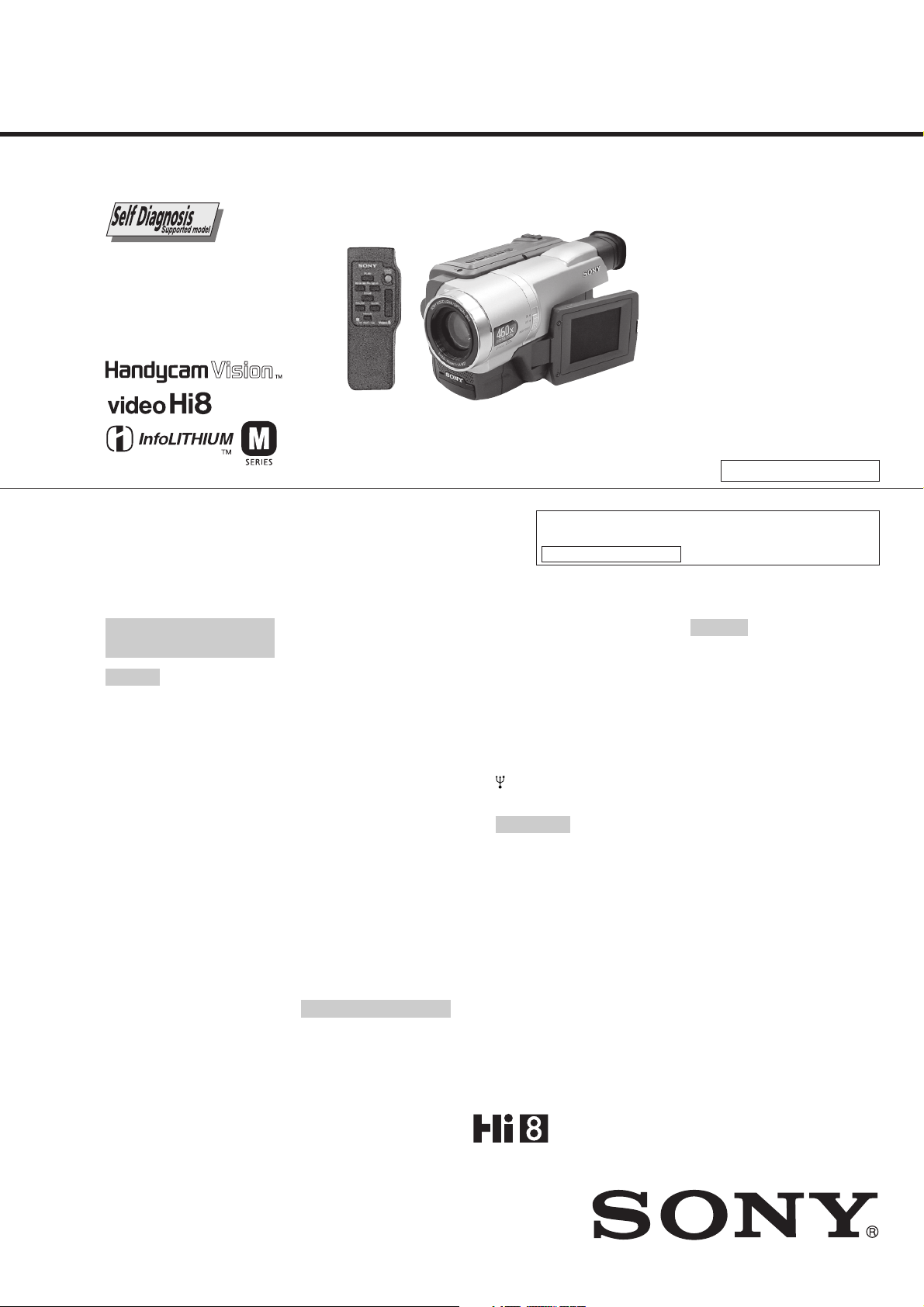
CCD-TRV107/TRV108/TRV308/
SERVICE MANUAL
Ver 1.0 2001. 12
TRV408/TRV608
RMT-708
US Model
Canadian Model
CCD-TRV108/TRV308/TRV608
E Model
CCD-TRV107/TRV108/TRV308/
TRV408/TRV608
Korea Model
CCD-TRV408
Hong Kong Model
Tourist Model
CCD-TRV107/TRV408
Argentina Model
CCD-TRV108/TRV608
Video camera
recorder
System
Video recording system
2 rotary heads
Helical scanning
FM system
Audio recording system
Rotary heads, FM system
Video signal
NTSC color, EIA standards
Usable cassette
8mm video format cassette
Hi8 or standard 8
Recording/playback time (using
120 min. Standard 8/Hi8 video
cassette)
SP mode: 2 hours
LP mode: 4 hours
Fastforward/rewind time (using
120 min. Standard 8/Hi8 video
cassette)
Approx. 5 min.
Viewfinder
Electric Viewfinder (monochrome)
Image device
CCD-TRV107/TRV108:
3.0 mm (1 / 6 type) CCD
(Charge Coupled Device)
Approx. 270 000 pixels
(Effective: Approx. 250 000 pixels)
CCD-TRV308/TRV408/TRV608:
4.5mm (1/4 type) CCD
(Charge Coupled Device)
Approx. 320 000 pixels
(Effective: Approx. 200 000 pixels)
Photo : CCD-TRV108
SPECIFICATIONS
Lens
Combined power zoom lens
Filter diameter 37 mm (1 7/16 in.)
CCD-TRV107:
20
×
(Optical), 450× (Digital)
CCD-TRV108/TRV308:
20
×
(Optical), 460× (Digital)
CCD-TRV408/TRV608:
20
×
(Optical), 560× (Digital)
Focal length
3.6 - 72 mm (5/32 - 2 7/8 in.)
When converted to a 35 mm still
camera
CCD-TRV107/TRV108:
51.8 - 1 036 mm (2 - 40 6 / 8 in.)
CCD- TRV308/TRV408/TRV608:
41 - 820 mm (1 5 / 8 - 32 3 / 8 in.)
Color temperature
Auto
Minimum illumination
CCD-TRV107/TRV108:
1 lx (lux) (F 1.4)
CCD-TRV308/TRV408/TRV608:
0.4 lx (lux) (F 1.4)
0 lx (lux) (in the NightShot mode)*
* Objects unable to be seen due to
the dark can be shot with
infrared lighting.
Input/output connectors
S video output
4-pin mini DIN
Luminance signal: 1 Vp-p,
75 Ω (ohms), unbalanced
Chrominance signal: 0.286 Vp-p,
75 Ω (ohms), unbalanced
Brazilian Model
M2100 MECHANISM
For MECHANISM ADJUSTMENT, refer to the “8mm
Video MECHANICAL ADJUSTMENT MANUAL
M2000 MECHANISM ” (9-929-861-11).
Audio/Video output
AV MINIJACK, 1 Vp-p, 75 Ω
(ohms), unbalanced, sync negative
327 mV, (at output impedance
more than 47 kΩ (kilohms))
Output impedance with less than
2.2 kΩ (kilohms)/Monaural
minijack
(ø 3.5 mm)
RFU DC OUT
Mini-mini jack (ø 2.5 mm)
DC 5V
USB jack (CCD-TRV608 only)
mini-B
LCD screen
Picture
CCD-TRV107/TRV108/TRV308/
TRV408:
6.2 cm (2.5 type)
×
37.4 mm (2 × 1 1/2 in.)
50.3
CCD-TRV608:
7.5 cm (3 type)
×
43.8 mm (2 1/2 × 1 3/4 in.)
61.0
Total dot number
CCD-TRV107/TRV108/TRV308/
TRV408:
61 600 (280
CCD-TRV608:
123 200 (560
×
220)
×
220)
General
Power requirements
7.2 V (battery pack)
8.4 V (AC power adaptor)
Average power consumption
(when using the battery pack)
During camera recording using
LCD
CCD-TRV107/TRV108/TRV308/
TRV408: 2.6 W
CCD-TRV608: 3.1 W
Viewfinder
1.9 W
Operating temperature
0 °C to 40 °C (32 °F to 104 °F)
Recommended charging
temperature
10 °C to 30 °C (50 °F to 86 °F)
Storage temperature
–20 °C to +60 °C (–4 °F to +140 °F)
Dimensions (Approx.)
×
102 × 197 mm
90
×
4 1/8 × 7 7/8 in.)
(3 5/8
(w/h/d)
— Continued on next page —
VIDEO CAMERA RECORDER
CCD-TRV108
IX
Page 2

CCD-TRV107/TRV108/TRV308/TRV408/TRV608
Mass (approx.)
CCD-TRV107/TRV108/TRV308/
TRV408:
850 g (1 lb 14 oz)
CCD-TRV608:
870 g (1 lb 14 oz)
main unit only
CCD-TRV107/TRV108/TRV308:
990 g (2 lb 3 oz)
CCD-TRV408/TRV608:
1.0 kg (2 lb 3 oz)
including the battery pack
NP-FM30, 120 min. Hi8 cassette,
lens cap and shoulder strap
Supplied accessories
See page 3.
AC power adaptor
Power requirements
100 - 240 V AC, 50/60 Hz
Power consumption
23 W
Output voltage
DC OUT: 8.4 V, 1.5 A in the
operating mode
Operating temperature
0 °C to 40 °C (32 °F to 104 °F)
Storage temperature
–20 °C to +60 °C (–4 °F to +140 °F)
Dimensions (approx.)
× 39 × 62 mm
125
× 1 9/16 × 2 1/2 in.)
(5
(w/h/d)
excluding projecting parts
Mass (approx.)
280 g (9.8 oz)
excluding power cord
CAUTION :
Danger of explosion if battery is incorrectly replaced.
Replace only with the same or equivalent type.
SAFETY-RELATED COMPONENT WARNING!!
COMPONENTS IDENTIFIED BY MARK 0 OR DOTTED LINE WITH
MARK 0 ON THE SCHEMATIC DIAGRAMS AND IN THE PARTS
LIST ARE CRITICAL TO SAFE OPERATION. REPLACE THESE
COMPONENTS WITH SONY PARTS WHOSE PART NUMBERS
APPEAR AS SHOWN IN THIS MANUAL OR IN SUPPLEMENTS
PUBLISHED BY SONY.
Battery pack
Maximum output voltage
DC 8.4 V
Output voltage
DC 7.2 V
Capacity
5.0 Wh (700 mAh)
Operating temperature
0 °C to 40 °C (32 °F to 104 °F)
Dimensions (approx.)
× 20.5 × 55.6 mm
38.2
× 13/16 × 2 1/4 in.)
(1 9/16
(w/h/d)
Mass (approx.)
65 g (2.3 oz)
Type
Lithium ion
Design and specifications are
subject to change without notice.
ATTENTION AU COMPOSANT AYANT RAPPORT
LES COMPOSANTS IDENTIFÉS PAR UNE MARQUE 0 SUR LES
DIAGRAMMES SCHÉMATIQUES ET LA LISTE DES PIÈCES SONT
CRITIQUES POUR LA SÉCURITÉ DE FONCTIONNEMENT. NE
REMPLACER CES COMPOSANTS QUE PAR DES PIÈSES SONY
DONT LES NUMÉROS SONT DONNÉS DANS CE MANUEL OU
DANS LES SUPPÉMENTS PUBLIÉS PAR SONY.
À LA SÉCURITÉ!
SAFETY CHECK-OUT
After correcting the original service problem, perform the following
safety checks before releasing the set to the customer.
1. Check the area of your repair for unsoldered or poorly-soldered
connections. Check the entire board surface for solder splashes
and bridges.
2. Check the interboard wiring to ensure that no wires are
"pinched" or contact high-wattage resistors.
3. Look for unauthorized replacement parts, particularly
transistors, that were installed during a previous repair . Point
them out to the customer and recommend their replacement.
4. Look for parts which, through functioning, show obvious signs
of deterioration. Point them out to the customer and
recommend their replacement.
5. Check the B+ voltage to see it is at the values specified.
6. Flexible Circuit Board Repairing
• Keep the temperature of the soldering iron around 270˚C
during repairing.
• Do not touch the soldering iron on the same conductor of the
circuit board (within 3 times).
• Be careful not to apply force on the conductor when soldering
or unsoldering.
Unleaded solder
Boards requiring use of unleaded solder are printed with the leadfree mark (LF) indicating the solder contains no lead.
(Caution: Some printed circuit boards may not come printed with
the lead free mark due to their particular size.)
: LEAD FREE MARK
Unleaded solder has the following characteristics.
• Unleaded solder melts at a temperature about 40°C higher than
ordinary solder.
Ordinary soldering irons can be used but the iron tip has to be
applied to the solder joint for a slightly longer time.
Soldering irons using a temperature regulator should be set to
about 350°C.
Caution: The printed pattern (copper foil) may peel away if the
heated tip is applied for too long, so be careful!
• Strong viscosity
Unleaded solder is more viscous (sticky, less prone to flow) than
ordinary solder so use caution not to let solder bridges occur such
as on IC pins, etc.
• Usable with ordinary solder
It is best to use only unleaded solder but unleaded solder may
also be added to ordinary solder.
— 2 —
Page 3
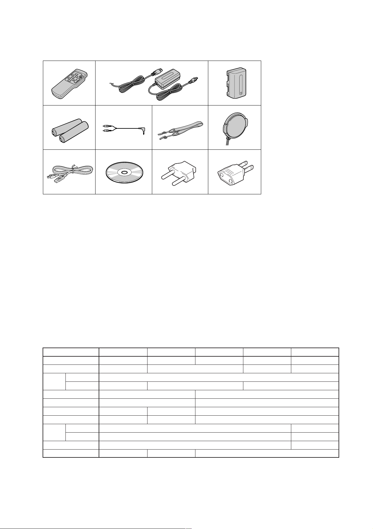
CCD-TRV107/TRV108/TRV308/TRV408/TRV608
• SUPPLIED ACCESSORIES
Make sure that the following accessories are supplied with your camcorder .
1
4
8
1 Wireless Remote Commander (CCD-
TRV107/TRV408 only) (1)
2 AC-L10A/L10B/L10C AC power
adaptor (1), Power cord (1)
3 NP-FM30 battery pack (1)
4 Size AA (R6) battery for Remote
Commander (CCD-TRV107/TRV408
only) (2)
5 A/V connecting cable (1)
2
56
9
3
7
qa0
7 Lens cap (1)
8 USB Cable (CCD-TRV608 only) (1)
9 CD-ROM (SPVD-008 (I) USB Driver)
(CCD-TRV608 only) (1)
0 2-pin adaptor
CCD-TRV107: JE/TRV408: JE only
qa 2-pin adaptor
CCD-TRV107: E, HK/
TRV408: E, HK only
(1)
(1)
6 Shoulder strap (1)
Table for difference of function
Model
Destination
Remote Commander
Lens
Optical
Zoom
CCD-TRV107
E, HK, JE
RMT-708
450×
CCD imager size
Steady shot
View finder type
Type S
View finder backlight
LCD
Size
Pixel
USB connector
Video light
• Abbreviation
CND : Canadian model
HK : Hong Kong model
KR : Korea model
JE : Tourist model
AR : Argentina model
BR : Brazilian model
CCD-TRV108
US, CND, E, AR, BR
CCD-TRV308
US, CND, E
✕
CCD-TRV408
E, HK, KR, JE
RMT-708
CCD-TRV608
US, CND, E, AR
✕
20×
460× 560×
1/6 inch
✕
Type M
a
✕
2.5 inch
61K
✕
a
✕
1/4 inch
a
Type S
a
3 inch
123K
a
a
— 3 —
Page 4

CCD-TRV107/TRV108/TRV308/TRV408/TRV608
TABLE OF CONTENTS
SERVICE NOTE
1. POWER SUPPLY DURING REPAIRS ····························· 7
2. TO TAKE OUT A CASSETTE WHEN NOT EJECT
(FORCE EJECT) ································································ 7
SELF-DIAGNOSIS FUNCTION
1. Self-diagnosis Function ······················································ 8
2. Self-diagnosis Display························································ 8
3. Service Mode Display ························································ 8
3-1. Display Method ·································································· 8
3-2. Switching of Backup No. ··················································· 8
3-3. End of Display···································································· 8
4. Self-diagnosis Code Table ·················································· 9
1. GENERAL
Main Features ············································································ 1-1
Quick Start Guide ······································································1-1
Getting started
Using this manual ··································································1-2
Checking supplied accessories ·············································· 1-2
Step 1 Preparing the power supply ········································1-2
Installing the battery pack··················································· 1-2
Charging the battery pack ···················································1-3
Connecting to a wall outlet ·················································1-3
Step 2 Setting the date and time ············································1-4
Step 3 Inserting a cassette······················································1-4
Recording – Basics
Recording a picture································································1-4
Shooting backlit subjects – BACK LIGHT ··························· 1-6
Shooting in the dark – NightShot ··········································1-6
Superimposing the date and time on pictures ························1-6
Checking the recording – END SEARCH·····························1-7
Playback – Basics
Playing back a tape ································································1-7
Viewing the recording on TV ················································1-8
Advanced Recording Operations
Using the wide mode ·····························································1-8
Using the fader function ························································1-8
Using special effects – Picture effect·····································1-9
Using the PROGRAM AE function ·······································1-9
Adjusting the exposure manually ········································1-10
Focusing manually·······························································1-10
Superimposing a title ···························································1-10
Making your own titles ························································1-11
Using the built-in light·························································1-11
Editing
Dubbing a tape ·····································································1-12
Dubbing a tape easily – Easy dubbing································· 1-12
PC Connection (CCD-TRV608 only)
Viewing images using your computer – USB Streaming
(Windows users only) ·······················································1-14
Customizing Y our Camcorder
Changing the menu settings·················································1-16
Troubleshooting
Types of trouble and their solutions·····································1-18
Self-diagnosis display ··························································1-19
Warning indicators and messages ········································1-19
Additional Information
About video cassettes ··························································1-20
About the “InfoLITHIUM” battery pack·····························1-20
Using your camcorder abroad··············································1-20
Maintenance information and precautions···························1-21
Quick Reference
Identifying the parts and controls ········································1-22
2. DISASSEMBLY
2-1. VIDEO LIGHT (VIDEO LIGHT MODEL) ···················2-2
2-2. LCD SECTION (PD-156 BOARD) ································2-3
2-3. VF-150, LB-073 BOARDS
(TRV107/TRV308/TRV408/TRV608) ····························2-4
2-4. LIQUID CRYSTAL INDICATOR MODULE (TRV108) ···2-5
2-5. FRONT PANEL SECTION (SI-033 BOARD) ··············· 2-6
2-6. CABINET (L) SECTION················································2-7
2-7. CABINET (R) SECTION ···············································2-8
2-8. EVF SECTION································································2-8
2-9. BATTERY PANEL SECTION ········································2-9
2-10. LENS SECTION ·····························································2-9
2-11. VC-272 BOARD ···························································2-10
2-12. CONTROL SWITCH BLOCK (CF-2000) ···················2-10
2-13. MECHANISM DECK··················································· 2-13
2-14. HINGE ASSEMBL Y·····················································2-13
2-15. CIRCUIT BOARDS LOCATION ·································2-14
2-16. FLEXIBLE BOARDS LOCATION ······························2-15
3. BLOCK DIAGRAMS
3-1. OVERALL BLOCK DIAGRAM (1/2) ···························3-3
3-2. OVERALL BLOCK DIAGRAM (2/2) ···························3-5
3-3. CAMERA/VIDEO BLOCK DIAGRAM (1/2) ···············3-7
3-4. CAMERA/VIDEO BLOCK DIAGRAM (2/2) ···············3-9
3-5. USB BLOCK DIAGRAM·············································3-11
3-6. VTR/CAMERA CONTROL BLOCK DIAGRAM·······3-13
3-7. SERVO BLOCK DIAGRAM········································3-15
3-8. MODE CONTROL BLOCK DIAGRAM ·····················3-17
3-9. AUDIO BLOCK DIAGRAM ········································3-19
3-10. LCD BLOCK DIAGRAM ············································3-21
3-11. EVF BLOCK DIAGRAM·············································3-23
3-12. POWER BLOCK DIAGRAM (1/2)······························3-25
3-13. POWER BLOCK DIAGRAM (2/2)······························3-27
4. PRINTED WIRING BOARDS AND
SCHEMATIC DIAGRAMS
4-1. FRAME SCHEMATIC DIAGRAM (1/2)·······················4-1
FRAME SCHEMATIC DIAGRAM (2/2)·······················4-3
4-2. PRINTED WIRING BOARDS AND
SCHEMATIC DIAGRAMS ············································4-5
• CD-354 (CCD IMAGER)
PRINTED WIRING BOARD AND
SCHEMATIC DIAGRAM ······························4-7
• LB-073 (BACK LIGHT (EVF))
PRINTED WIRING BOARD AND
SCHEMATIC DIAGRAM ······························4-9
• VF-150 (RGB DRIVE/TG)
PRINTED WIRING BOARD ·······················4-11
• VF-150 (RGB DRIVE/TG)
SCHEMATIC DIAGRAM ····························4-13
• SI-033 (STEADY SHOT, MIC)
PRINTED WIRING BOARD ·······················4-15
• SI-033 (STEADY SHOT, MIC)
SCHEMATIC DIAGRAM ····························4-17
• PD-156 (RGB DRIVE, TIMING GENERATOR, LCD
DRIVE, BACKLIGHT DRIVE)
PRINTED WIRING BOARD ·······················4-19
• PD-156 (RGB DRIVE, TIMING GENERATOR)(1/2)
SCHEMATIC DIAGRAM ····························4-23
• PD-156 (LCD DRIVE, BACKLIGHT DRIVE)(2/2)
SCHEMATIC DIAGRAM ····························4-25
• CF-2000 (CONTROL SWITCH BLOCK)
SCHEMATIC DIAGRAM ····························4-27
— 4 —
Page 5

CCD-TRV107/TRV108/TRV308/TRV408/TRV608
• LS-057 (S/T REEL SENSOR), FP-228 (DEW SENSOR),
FP-299 (MODE SWITCH), FP-300 (TAPE TOP),
FP-302 (TAPE END), FP-301 (TAPE LED)
FLEXIBLE BOARDS AND
SCHEMATIC DIAGRAMS·························· 4-29
• VC-272 (CAMERA PROCESSOR AMP, Y/C
PROCESSOR, FOCUS/ZOOM MOTOR DRIVE,
REC/PB AMP, LINE OUT AMP, SERVO, MODE
CONTROL, STEADY SHOT, HI CONTROL, AUDIO,
DC-DC CONVERTER, CONNECTOR, USB SIGNAL)
PRINTED WIRING BOARD ·······················4-31
• VC-272(CAMERA PROCESSOR AMP)(1/12)
SCHEMATIC DIAGRAM ····························4-35
• VC-272(Y/C PROCESSOR)(2/12)
SCHEMATIC DIAGRAM ····························4-37
• VC-272(FOCUS/ZOOM MOTOR DRIVE)(3/12)
SCHEMATIC DIAGRAM ····························4-39
• VC-272(REC/PB AMP)(4/12)
SCHEMATIC DIAGRAM ····························4-41
• VC-272(LINE OUT AMP)(5/12)
SCHEMATIC DIAGRAM ····························4-43
• VC-272(SER V O)(6/12)
SCHEMATIC DIAGRAM ····························4-45
• VC-272(MODE CONTROL, STEADY SHOT)(7/12)
SCHEMATIC DIAGRAM ····························4-47
• VC-272(HI CONTROL)(8/12)
SCHEMATIC DIAGRAM ····························4-49
• VC-272(AUDIO)(9/12)
SCHEMATIC DIAGRAM ····························4-51
• VC-272(DC-DC CONVERTER)(10/12)
SCHEMATIC DIAGRAM ····························4-53
• VC-272(CONNECTOR)(11/12)
SCHEMATIC DIAGRAM ····························4-55
• VC-272(USB SIGNAL PROCESS)(12/12)
SCHEMATIC DIAGRAM ····························4-57
• FP-397 FLEXIBLE BOARD ·····································4-59
4-3. WAVEFORMS ······························································ 4-60
4-4. MOUNTED PARTS LOCATION ································· 4-63
5. ADJUSTMENTS
1.
Adjusting items when replacing main parts and boards
5-1. CAMERA SECTION ADJUSTMENT ···························5-4
1-1. PREPARA TIONS BEFORE ADJUSTMENT
(CAMERA SECTION) ···················································5-4
1-1-1.List of Service Tools························································5-4
1-1-2.Preparations ·····································································5-5
1-1-3.Precaution ········································································5-7
1. Setting the Switch···························································· 5-7
2. Order of Adjustments ······················································5-7
3. Subjects ···········································································5-7
1-2. INITIALIZATION OF D, E, F, 7 PAGE DATA ··············5-8
1. Initializing the D, E, F, 7 Page Data ································5-8
2. Modification of D, E, F, 7 Page Data ······························5-8
3. D Page Table····································································5-8
4. F Page table ·····································································5-9
5. E Page Table ··································································5-11
6. 7 Page Table···································································5-11
1-3. CAMERA SYSTEM ADJUSTMENTS························5-12
1. HALL Adjustment ·························································5-12
2. Flange Back Adjustment (Using Minipattern Box)·······5-13
3. Flange Back Adjustment (Using Flange Back Adjustment
Chart and Subject More Than 500m Away) ··················5-14
3-1. Flange Back Adjustment (1)··········································5-14
3-2. Flange Back Adjustment (2)··········································5-14
4. Flange Back Check························································5-15
5. Picture Frame Setting ····················································5-15
6. Color Reproduction Adjustment····································5-16
.··5-2
7. Auto White Balance & LV Standard Data Input ···········5-17
8. Auto White Balance Adjustment ···································5-18
9. White Balance Check ····················································5-19
Steady Shot Check (CCD-TRV308/TRV408/TRV608) ··
10.
1-4. ELECTRONIC VIEWFINDER SYSTEM
ADJUSTMENT
(CCD-TRV107/TRV308/TRV408/TRV608)·················5-21
1. RGB AMP Adjustment (VF-150 board)························5-22
1-1. Automatic Adjustment···················································5-22
1-2. Manual Adjustment ······················································· 5-22
2. Contrast Adjustment (VF-150 board)····························5-23
2-1. Automatic Adjustment···················································5-23
2-2. Manual Adjustment ······················································· 5-23
1-5. LCD SYSTEM ADJUSTMENT ··································· 5-24
1. LCD Type Check···························································5-24
2. VCO Adjustment (PD-156 board)·································5-25
3. RGB AMP Adjustment (PD-156 board)························5-25
4. Contrast Adjustment (PD-156 board)····························5-26
5. COM AMP Adjustment (PD-156 board) ·······················5-26
6. V-COM Adjustment (PD-156 board) ····························5-27
7. White Balance Adjustment (PD-156 board)··················5-27
5-2. MECHANISM SECTION ADJUSTMENT··················5-28
2-1. ADJUSTMENT REMOTE COMMANDER ················5-28
2-2. OPERA TING WITHOUT CASSETTE ························ 5-28
2-3. TAPE PATH ADJUSTMENT········································5-28
1. Preparations for Adjustment··········································5-28
5-3. VIDEO SECTION ADJUSTMENTS ···························5-29
3-1. PREPARA TIONS BEFORE ADJUSTMENTS ············ 5-29
3-1-1. Equipment to Required ·················································5-29
3-1-2.Precautions on Adjusting···············································5-30
3-1-3.Adjusting Connectors ····················································5-31
3-1-4.Connecting the Equipment ············································5-31
3-1-5.Alignment Tape ·····························································5-32
3-1-6.Output Level and Impedance·········································5-32
3-1-7.Recording Mode (Standard 8/Hi8) switching ···············5-32
3-2. SYSTEM CONTROL SYSTEM ADJUSTMENT ········5-33
1. Initialization of D, E, F, 7 Page Data·····························5-33
3-3. SERV O ADJUSTMENT ···············································5-33
1. CAP FG Offset Adjustment (VC-272 board) ················5-33
2. Switching Position Adjustment (VC-272 board)···········5-33
3-4. VIDEO SYSTEM ADJUSTMENTS····························· 5-34
28 MHz Origin Oscillation Adjustment (VC-272 board) ·
1.
2. AFC f0 Adjustment (VC-272 board) ·····························5-34
3. Y OUT Level Adjustment (VC-272 board) ···················5-35
4. C OUT Level Adjustment (VC-272 board) ···················5-35
5. REC Y Current Adjustment (VC-272 board) ················5-36
6. REC C/AFM Current Adjustment ·································5-37
6-1. Preparations ··································································· 5-37
6-2. REC C Current Check (VC-272 board) ························5-37
6-3. REC AFM Current Adjustment (VC-272 board) ··········5-38
6-4. Processing after completed adjustment ·························5-38
3-5. AUDIO SYSTEM ADJUSTMENTS ····························5-39
1. 1.5 MHz Deviation Adjustment (VC-272 board) ··········5-39
2. BPF f0 Adjustment (VC-272 board) ······························5-39
5-4. SERVICE MODE··························································5-40
4-1. ADJUSTMENT REMOTE COMMANDER ················5-40
1. Using the Adjustment Remote Commander··················5-40
2. Precautions Upon Using the Adjustment Remote
Commander ···································································5-40
4-2. DATA PROCESS···························································5-41
4-3. SERVICE MODE··························································5-42
1. Test Mode Setting··························································5-42
2. Emergency Memory Address ········································5-43
2-1. EMG code (Emergency code) ·······································5-43
2-2. MSW codes ···································································5-44
3. Bit V alue Discrimination ···············································5-45
4. Switch check (1) ····························································5-45
5-20
5-34
— 5 —
Page 6

CCD-TRV107/TRV108/TRV308/TRV408/TRV608
5. Switch check (2) ····························································5-45
6. Switch check (3) ····························································5-46
7. Record of Use check······················································5-46
8. Record of Self-diagnosis check ·····································5-47
6. REPAIR PARTS LIST
6-1. EXPLODED VIEWS ······················································6-1
6-1-1.OVERALL SECTION·····················································6-1
6-1-2.F PANEL SECTION ······················································· 6-2
6-1-3.CABINET (L) SECTION················································6-3
6-1-4.BATTERY PANEL SECTION ········································6-4
6-1-5.EVF SECTION································································ 6-5
6-1-6.LENS SECTION ·····························································6-6
6-1-7 CABINET (R) SECTION ··············································· 6-7
6-1-8 CASSETTE COMPARTMENT ASSY, DRUM ASSY ···6-8
6-1-9.LS CHASSIS BLOCK ASSEMBLY·······························6-9
6-1-10.
MECHANICAL CHASSIS BLOCK ASSEMBLY-1 ····
6-1-11.
MECHANICAL CHASSIS BLOCK ASSEMBLY-2 ····
6-2. ELECTRICAL PARTS LIST ········································6-12
* Color reproduction frame are shown on page 215.
6-10
6-11
— 6 —
Page 7
CCD-TRV107/TRV108/TRV308/TRV408/TRV608
4
SERVICE NOTE
1. POWER SUPPLY DURING REPAIRS
In this unit, about 10 seconds after power is supplied (8.4V) to the battery terminal, the power is shut off so that the unit cannot operate.
The following method is available to prevent this.
Method:
Use the DC IN terminal. (Use the AC power adaptor.)
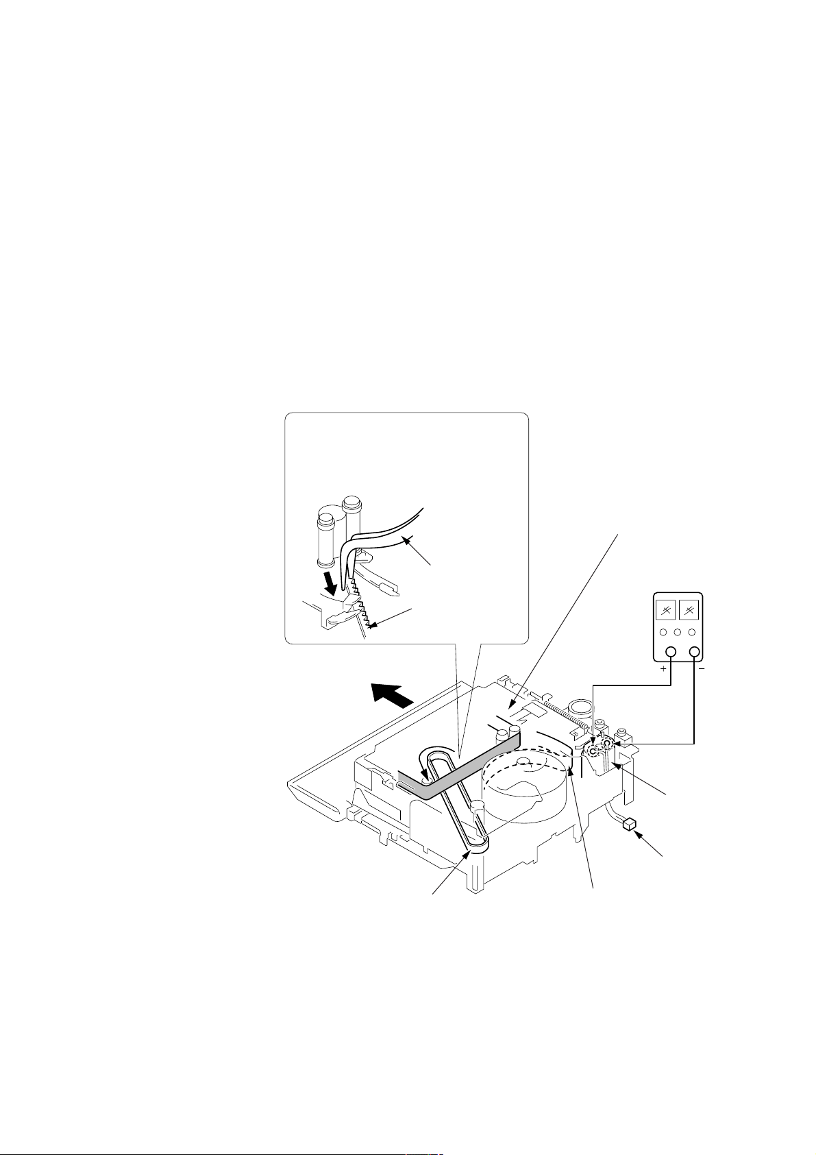
2. TO TAKE OUT A CASSETTE WHEN NOT EJECT (FORCE EJECT)
1 Refer to 2-5. to remove the front panel assembly.
2 Refer to 2-7. to remove the cabinet (R) assembly.
3 Open the control switch block (FK-2000).
4 Refer to 2-6. to remove the cassette lid assembly.
5 Refer to 2-6. to remove the cabinet (L) assembly.
6 Disconnect CN704 (2P) of VC-272 board.
7 Add +5V from the DC POWER SUPPLY and unload with a pressing the cassette compartment.
9
Let go your hold the cassette
compartment and rise the cassette
compartment to take out a cassette.
8
Pull the timing belt in the direction of
A
arrow
the cassette compartment (take care
not to damage) to adjust the bending
of a tape.
A
with a pincette while pressing
Pincette
Timing belt
A
Press the cassette compartment not to
rise the cassette compartment
[DC power supply]
(+5V)
Loading motor
Timing belt
— 7 —
Disconnect CN70
of VC-272 board.
Adjust the bending of a tape
Page 8
CCD-TRV107/TRV108/TRV308/TRV408/TRV608
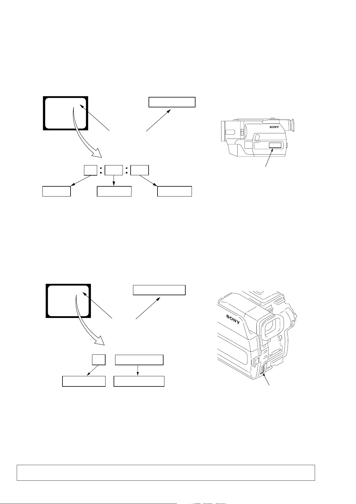
SELF-DIAGNOSIS FUNCTION
1. Self-diagnosis Function
When problems occur while the unit is operating, the self-diagnosis
function starts working, and displays on the viewfinder or LCD or
Display window what to do. This function consists of tw o display;
self-diagnosis display and service mode display.
Details of the self-diagnosis functions are provided in the Instruction
manual.
Viewfinder or LCD Display window
C : 3 1 : 1 1
Repaired by:
C : Corrected by customer
H : Corrected by dealer
E : Corrected by service
engineer
Blinks at 3.2Hz
C
Indicates the appropriate
step to be taken.
E.g.
31 ....Reload the tape.
32 ....Turn on power again.
3 1
Block
1 1
C : 3 1 : 11
Refer to page 9 and 10.
Self-diagnosis Code Table.
2. Self-diagnosis Display
When problems occur while the unit is operating, the counter of the
viewfinder or LCD or Display window shows a 4-digit display
consisting of an alphabet and numbers, which blinks at 3.2 Hz. This
5-character display indicates the “repaired by:”, “block” in which
the problem occurred, and “detailed code” of the problem.
Display window
Detailed Code
3. Service Mode Display
The service mode display shows up to six self-diagnosis codes shown in the past.
3-1. Display Method
While pressing the “STOP” key, set the switch from OFF to “VTR or PLAYER”, and continue pressing the “STOP” key for 5 seconds
continuously. The service mode will be displayed, and the counter will show the backup No. and the 5-character self-diagnosis codes.
Viewfinder or LCD
[3] C : 3 1 : 1 1
Lights up
[3]
Backup No.
Order of previous errors
C : 3 1 : 1 1
Self-diagnosis Codes
3-2. Switching of Backup No.
By rotating the control dial, past self-diagnosis codes will be shown in order. The backup No. in the [] indicates the order in which the
problem occurred. (If the number of problems which occurred is less than 6, only the number of problems which occurred will be shown.)
[1] : Occurred first time [4] : Occurred fourth time
[2] : Occurred second time [5] : Occurred fifth time
[3] : Occurred third time [6] : Occurred the last time
Display window
3 C : 3 1 : 11
Control dial
3-3. End of Display
Turning OFF the power supply will end the service mode display.
Note: The “self-diagnosis display” data will be backed up by the built-in rechargeable lithium battery (CF-2000 block BT001).
When the cabinet (R) assembly is disconnected, the “self-diagnosis display” data will be lost by initialization.
— 8 —
Page 9

4. Self-diagnosis Code Table
Self-diagnosis Code
CCD-TRV107/TRV108/TRV308/TRV408/TRV608
Function
Repaired by:
C
C
C
C
C
C
C
C
C
C
C
C
C
C
C
C
C
C
C
C
C
C
C
C
C
C
C
C
C
Block
04
21
22
31
31
31
31
31
31
31
31
31
31
31
31
31
32
32
32
32
32
32
32
32
32
32
32
32
32
Detailed
Code
00
00
00
10
11
20
21
22
23
30
31
40
41
42
43
44
10
11
20
21
22
23
30
31
40
41
42
43
44
Symptom/State
Non-standard battery is used.
Condensation.
Video head is dirty.
LOAD direction. Loading does not
complete within specified time
UNLOAD direction. Loading does not
complete within specified time
T reel side tape slacking when unloading
S reel
side tape slacking when unloading
T reel fault.
S reel fault.
FG fault when starting capstan.
FG fault during normal capstan operations.
FG fault when starting drum.
PG fault when starting drum.
FG fault during normal drum operations.
PG fault during normal drum operations.
Phase fault during normal drum operations.
LOAD direction loading motor time-
out.
UNLOAD direction loading motor
time-out.
T reel side tape slacking when
unloading.
S reel side tape slacking when
unloading.
T reel fault.
S reel fault.
FG fault when starting capstan.
FG fault during normal capstan
operations.
FG fault when starting drum.
PG fault when starting drum.
FG fault during normal drum
operations.
PG fault during normal drum
operations.
Phase fault during normal drum
operations.
Correction
Use the InfoLITHIUM battery.
Remove the cassette, and insert it again after one hour.
Clean with the optional cleaning cassette.
Load the tape again, and perform operations from the beginning.
Load the tape again, and perform operations from the beginning.
.
Load the tape again, and perform operations from the beginning.
.
Load the tape again, and perform operations from the beginning.
Load the tape again, and perform operations from the beginning.
Load the tape again, and perform operations from the beginning.
Load the tape again, and perform operations from the beginning.
Load the tape again, and perform operations from the beginning.
Load the tape again, and perform operations from the beginning.
Load the tape again, and perform operations from the beginning.
Load the tape again, and perform operations from the beginning.
Load the tape again, and perform operations from the beginning.
Load the tape again, and perform operations from the beginning.
Remove the battery or power cable, connect, and perform
operations from the beginning.
Remove the battery or power cable, connect, and perform
operations from the beginning.
Remove the battery or power cable, connect, and perform
operations from the beginning.
Remove the battery or power cable, connect, and perform
operations from the beginning.
Remove the battery or power cable, connect, and perform
operations from the beginning.
Remove the battery or power cable, connect, and perform
operations from the beginning.
Remove the battery or power cable, connect, and perform
operations from the beginning.
Remove the battery or power cable, connect, and perform
operations from the beginning.
Remove the battery or power cable, connect, and perform
operations from the beginning.
Remove the battery or power cable, connect, and perform
operations from the beginning.
Remove the battery or power cable, connect, and perform
operations from the beginning.
Remove the battery or power cable, connect, and perform
operations from the beginning.
Remove the battery or power cable, connect, and perform
operations from the beginning.
— 9 —
Page 10

CCD-TRV107/TRV108/TRV308/TRV408/TRV608
Self-diagnosis Code
Block
Function
Repaired by:
E
61
E
61
E
62
E
62
*1: STEADY SHOT model (CCD-TRV308/TRV408/TRV608)
Detailed
Code
00
10
00
01
Symptom/State
Difficult to adjust focus
(Cannot initialize focus.)
Zoom operations fault
(Cannot initialize zoom lens.)
Handshake correction function does not
work well. (With pitch angular velocity
sensor output stopped.)
Handshake correction function does not
work well. (With yaw angular velocity
sensor output stopped.)
Correction
Inspect the lens block focus reset sensor (Pin qs of CN301 of VC-
272 board) when focusing is performed when the control dial is
rotated in the focus manual mode and the focus motor drive circuit
(IC301 of VC-272 board) when the focusing is not performed.
Inspect the lens block zoom reset sensor (Pin qf of CN301 of VC272 board) when zooming is performed when the zoom switch is
operated and the zoom motor drive circuit (IC301 of VC-272 board)
when zooming is not performed.
Inspect pitch angular velocity sensor (SE750 of SI-033 board)
peripheral circuits. *1
Inspect yaw angular velocity sensor (SE751 of SI-033 board)
peripheral circuits. *1
— 10 —
Page 11
CCD-TRV107/TRV108/TRV308/TRV408/TRV608
Main Features
Taking moving images, and playing them back
•Recording a picture (p. 19)
•Playing back a tape (p. 29)
Capturing images on your computer*
•Viewing images recorded on a tape (p. 59)
•Viewing images live from your camcorder (p. 59)
Others
Functions to adjust exposure in the recording mode
•BACK LIGHT (p. 25)
•NightShot (p. 26)
•PROGRAM AE (p. 38)
•Built-in light*
•Manual exposure (p. 40)
Functions to give images more impact
•Digital zoom (p. 22)
The default setting is set to OFF. (To zoom greater than 20×, select the digital zoom
power in D ZOOM in the menu settings.)
•FADER (p. 35)
•Picture effect (p. 37)
•TITLE (p. 42)
Function to give a natural appearance to your recordings
•Manual focus (p. 41)
Functions to use in editing in the recording mode
•Wide mode (p. 33)
•Date and time (p. 16)
•ORC [MENU] (p. 70)
Function to use after recording
•Easy Dubbing (p. 51)
Function to make transition smooth
•END SEARCH (P.28)
1)
CCD-TRV608 only
*
2)
CCD-TRV107/TRV308/TRV408/TRV608 only
4
*
2)
(p. 46)
SECTION 1
GENERAL
1)
This section is extracted from
instruction manual.
Quick Start Guide
This chapter introduces you to the basic features of your
camcorder. See the page in parentheses “()” for more
information.
Connecting the power cord (p. 15)
Use the battery pack when using your camcorder outdoors (p. 11).
Quick Start Guide
AC power adaptor (supplied)
Inserting a cassette (p. 18)
1Open the lid of the
cassette compartment,
and press Z EJECT.
The cassette
compartment opens
automatically.
T
C
E
J
E
2Insert a cassette
into the cassette
compartment
with its window
facing out and the
write-protect tab
on the cassette up.
Open the DC IN
jack cover.
Connect the plug with
its v mark facing up.
3Close the cassette
compartment by
pressing the
on the cassette
compartment. The
cassette compartment
automatically goes
down.
Close the lid of the
cassette compartment.
mark
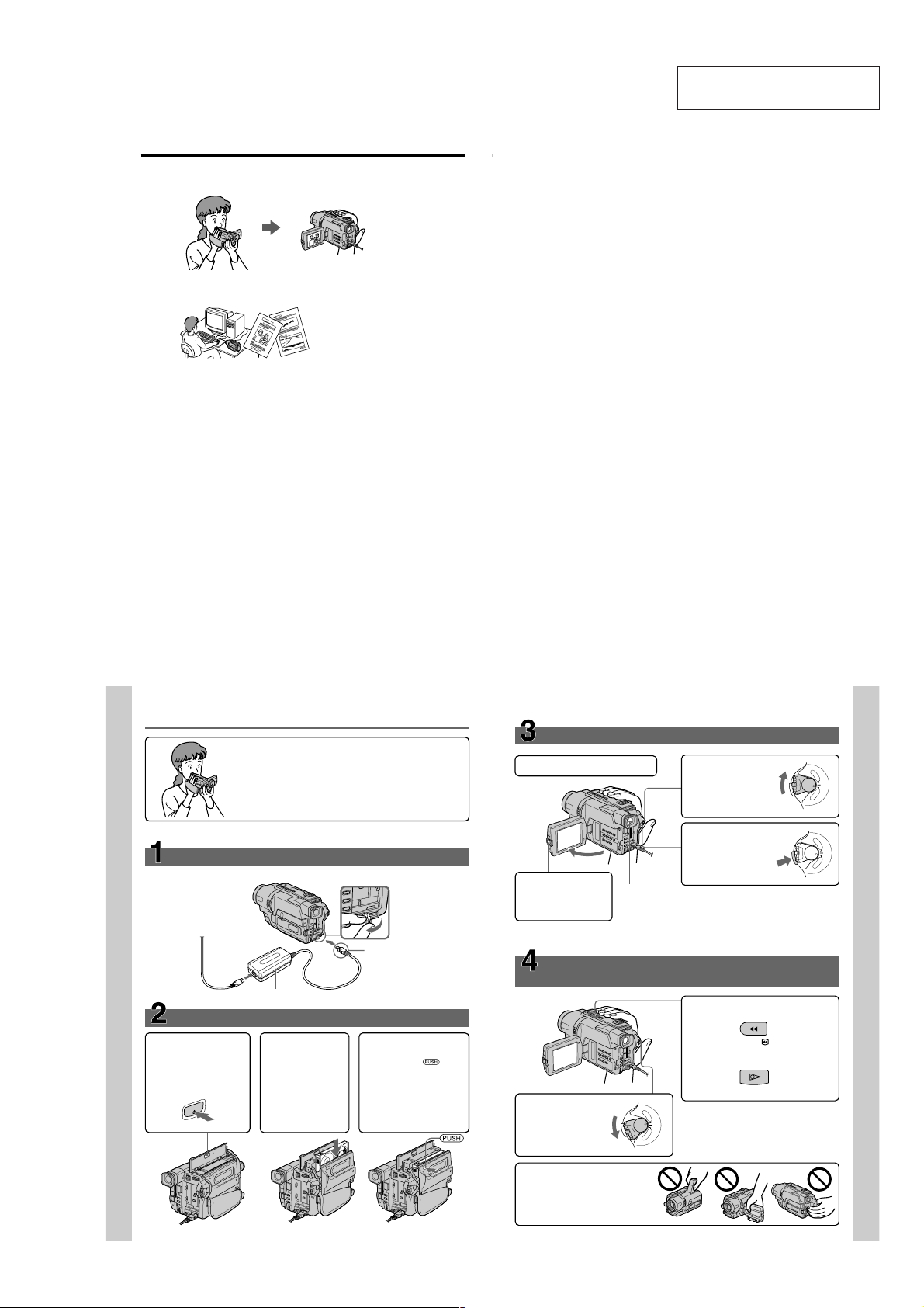
Recording a picture
1
Remove the lens cap.
3
Open the LCD panel
while pressing OPEN.
The picture appears
on the LCD screen.
When you purchase your camcorder, the clock setting is set to off. If you want to
record the date and time for a picture, set the clock setting before recording (p. 16).
Monitoring the playback picture on the LCD
screen
Viewfinder
When the LCD panel is closed, use the
viewfinder placing your eye against its eyecup.
The picture in the viewfinder is black and white.
Adjust the viewfinder lens to your eyesight (p. 23).
(p. 29)
(p. 19)
2
Set the POWER
switch to CAMERA
while pressing the
small green button.
4
Press START/STOP.
Your camcorder
starts recording. To
stop recording, press
START/STOP again.
2
Press m to rewind the tape.
REW
3
Press N to start playback.
PLAY
1
Set the POWER
switch to PLAYER
while pressing the
small green button.
P
L
A
Y
E
R
O
F
F
(
C
R
E
W
H
O
P
G
C
)
A
M
E
R
A
P
L
A
Y
E
R
O
F
F
P
(
O
C
W
ER
H
G
C
)
A
M
E
R
A
P
L
A
Y
E
R
O
F
F
PO
(
C
W
ER
H
G
C
)
A
M
E
R
A
Quick Start Guide
Note
Do not pick up your camcorder by
the viewfinder, the LCD panel, or
the battery pack.
6
7
1-1
Page 12
CCD-TRV107/TRV108/TRV308/TRV408/TRV608
— Getting started —
Using this manual
The instructions in this manual are for the five models listed in the table below. Before
you start reading this manual and operating your camcorder, check the model number
by looking at the bottom of your camcorder. The CCD-TRV608 is the model used for
illustration purposes. Otherwise, the model name is indicated in the illustrations. Any
differences in operation are clearly indicated in the text, for example, “CCD-TRV608
only.”
As you read through this manual, buttons and settings on your camcorder are shown in
capital letters.
e.g. Set the POWER switch to CAMERA.
When you carry out an operation, you can hear a beep sound to indicate that the
operation is being carried out.
Types of differences
CCDDigital Zoom 450× 460× 460× 560× 560×
LCD Screen 6.2 cm 6.2 cm 6.2 cm 6.2 cm 7.5 cm
Built-in light z — zzz
Remote sensor z ——z —
SteadyShot ——zzz
USB Streaming ————z
VF B.L. (Viewfinder backlight) z — zzz
z Provided
— Not provided
TRV107 TRV108 TRV308 TRV408 TRV608
(2.5 type) (2.5 type) (2.5 type) (2.5 type) (3 type)
Using this manual
Note on TV color systems
TV color systems differ from country to country. To view your recordings on a TV, you
need an NTSC system-based TV.
Precautions on camcorder care
Lens and LCD screen/finder (on mounted models only)
•The LCD screen and the finder are manufactured using extremely high-precision
technology so over 99.99% of the pixels are operational for effective use.
However, there may be some tiny black points and/or bright points (white, red,
blue or green in color) that constantly appear on the LCD screen and the finder.
These points are normal in the manufacturing process and do not affect the
recording in any way.
•Do not let your camcorder get wet. Keep your camcorder away from rain and sea
water. Letting your camcorder get wet may cause your camcorder to malfunction.
Sometimes this malfunction cannot be repaired [a].
•Never leave your camcorder exposed to temperatures above 60°C (140°F), such as in a
car parked in the sun or under direct sunlight [b].
•Be careful when placing the camera near a window or outdoors. Exposing the LCD
screen, the finder or the lens to direct sunlight for long periods may cause
malfunctions [c].
•Do not directly shoot the sun. Doing so might cause your camcorder to malfunction.
Take pictures of the sun in low light conditions such as dusk [d].
[a] [b]
[c] [d]
Getting started
8
Checking supplied accessories
Make sure that the following accessories are supplied with your camcorder.
1
4
8
1 Wireless Remote Commander (CCD-
TRV107/TRV408 only) (1) (p. 96)
2 AC-L10A/L10B/L10C AC power
adaptor (1), Power cord (1) (p. 15)
3 NP-FM30 battery pack (1) (p. 11, 12)
4 Size AA (R6) battery for Remote
Commander (CCD-TRV107/TRV408
only) (2) (p. 96)
Contents of the recording cannot be compensated if recording or playback is not
made due to a malfunction of the camcorder, storage media, etc.
2
56
9
5 A/V connecting cable (1) (p. 32)
6 Shoulder strap (1) (p. 91)
7 Lens cap (1) (p. 19, 95)
8 USB Cable (CCD-TRV608 only) (1)
9 CD-ROM (SPVD-008 USB Driver)
3
7
(p. 59)
(CCD-TRV608 only) (1) (p. 60)
Step 1 Preparing the power supply
Installing the battery pack
Slide the battery pack down until it clicks.
To remove the battery pack
Slide the battery pack out in the direction of the arrow while pressing V BATT down.
V BATT release lever
9
Getting started
10
11
1-2
Page 13
CCD-TRV107/TRV108/TRV308/TRV408/TRV608
Step 1 Preparing the power supply
Charging the battery pack
Use the battery pack after charging it for your camcorder.
Your camcorder operates only with the “InfoLITHIUM” battery pack (M series).
See page 81 for details of the “InfoLITHIUM” battery pack.
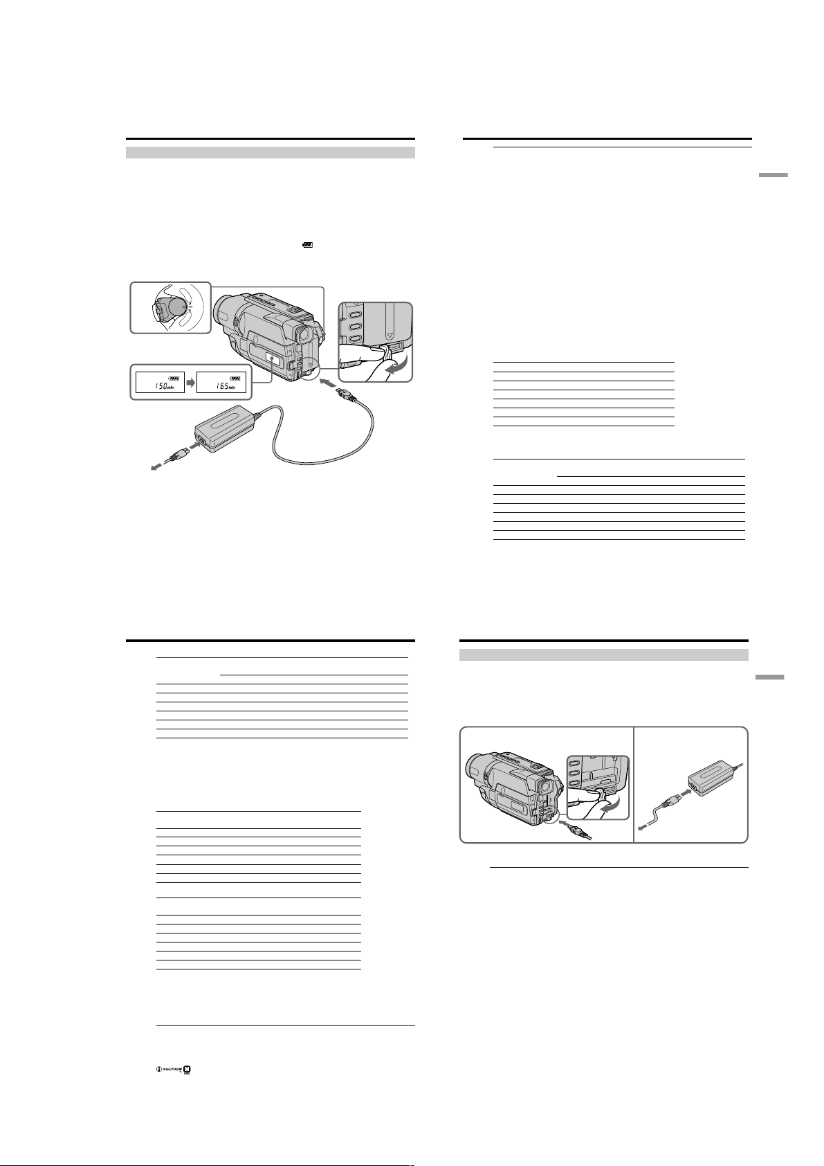
(1) Open the DC IN jack cover and connect the AC power adaptor supplied with
your camcorder to the DC IN jack with the plug’s v mark facing up.
(2) Connect the power cord to the AC power adaptor.
(3) Connect the power cord to a wall outlet.
(4) Set the POWER switch to OFF (CHG). Charging begins. The remaining battery
time is indicated in minutes on the display window.
When the remaining battery indicator changes to , normal charge is completed. To
fully charge the battery (full charge), leave the battery pack attached for about one hour
after normal charge is completed until “FULL” appears in the display window. Fully
charging the battery allows you to use the battery longer than usual.
P
L
A
Y
POWER
E
R
O
F
F
(
C
H
G
C
)
A
M
E
R
A
FULL
4
1
2,3
The number in the illustration of the display window may differ from that on your
camcorder.
After charging the battery pack
Disconnect the AC power adaptor from the DC IN jack on your camcorder.
Step 1 Preparing the power supply
Note
Prevent metallic objects from coming into contact with the metal parts of the DC plug of
the AC power adaptor. This may cause a short-circuit, damaging the AC power
adaptor.
Remaining battery time indicator
The remaining battery time you record with the viewfinder is displayed.
The remaining battery time indicator in the display window roughly indicates the
recording time with the viewfinder.
Until your camcorder calculates the actual remaining battery time
“– – – – min” appears in the display window.
While charging the battery pack, no indicator appears or the indicator flashes in
the display window in the following cases:
– The AC power adaptor is disconnected.
– The battery pack is not installed properly.
– Something is wrong with the battery pack.
We recommend charging the battery pack in an ambient temperature of between
10°C to 30°C (50°F to 86°F).
If the power goes off although the battery remaining indicator indicates that the
battery pack has enough power to operate
Charge the battery pack fully again so that the indication on the battery remaining
indicator is correct.
Charging time
Battery pack Full charge (normal charge)
NP-FM30 (supplied) 145 (85)
NP-FM50 150 (90)
NP-FM70 240 (180)
NP-QM71 260 (200)
NP-FM90 330 (270)
NP-FM91/QM91 360 (300)
Approximate number of minutes to charge an empty battery pack at 25°C (77°F)
Recording time
CCD-TRV107/TRV108/TRV308/TRV408
Battery pack the viewfinder the LCD screen
NP-FM30 (supplied) 165 90 120 65
NP-FM50 265 145 195 105
NP-FM70 540 295 400 220
NP-QM71 640 350 465 255
NP-FM90 820 450 600 330
NP-FM91/QM91 955 525 695 380
Recording with Recording with
Continuous* Typical** Continuous* Typical**
Getting started
12
Step 1 Preparing the power supply
CCD-TRV608
Battery pack the viewfinder the LCD screen
NP-FM30 (supplied) 165 90 100 55
NP-FM50 265 145 160 90
NP-FM70 540 295 335 185
NP-QM71 640 350 390 215
NP-FM90 820 450 505 275
NP-FM91/QM91 955 525 585 320
Approximate number of minutes when you use a fully charged battery pack
* Approximate continuous recording time at 25°C (77°F). The battery life will be
shorter if you use your camcorder in a cold environment.
** Approximate number of minutes when recording while you repeat recording start/
stop, zooming and turning the power on/off. The actual battery life may be shorter.
Playing time
CCD-TRV107/TRV108/TRV308/TRV408
Battery pack
NP-FM30 (supplied) 120 175
NP-FM50 195 280
NP-FM70 400 570
NP-QM71 465 675
NP-FM90 600 865
NP-FM91/QM91 695 1010
CCD-TRV608
Battery pack
NP-FM30 (supplied) 100 175
NP-FM50 160 280
NP-FM70 335 570
NP-QM71 390 675
NP-FM90 505 865
NP-FM91/QM91 585 1010
Approximate number of minutes when you use a fully charged battery pack
Approximate continuous playing time at 25°C (77°F). The battery life will be shorter if
you use your camcorder in a cold environment.
The recording and playing time of a normally charged battery are about 90% of those of
a fully charged battery.
What is the ”InfoLITHIUM”?
The “InfoLITHIUM” is a lithium ion battery pack which can exchange data such as
battery consumption with compatible electronic equipment. This unit is compatible
with the “InfoLITHIUM” battery pack (M series). Your camcorder operates only with
the “InfoLITHIUM” battery pack. “InfoLITHIUM” M series battery packs have the
mark.
14
“InfoLITHIUM” is a trademark of Sony Corporation.
Recording with Recording with
Continuous* Typical** Continuous* Typical**
Playing time Playing time
on LCD screen with LCD closed
Playing time Playing time
on LCD screen with LCD closed
Step 1 Preparing the power supply
Connecting to a wall outlet
When you use your camcorder for a long time, we recommend that you power it from a
wall outlet using the AC power adaptor.
(1) Open the DC IN jack cover, and connect the AC power adaptor to the DC IN
jack on your camcorder with the plug’s v mark facing up.
(2) Connect the power cord to the AC power adaptor.
(3) Connect the power cord to a wall outlet.
1 2,3
PRECAUTION
The set is not disconnected from the AC power source (wall outlet) as long as it is
connected to the wall outlet, even if the set itself has been turned off.
Notes
•The AC power adaptor can supply power even if the battery pack is attached to your
camcorder.
•The DC IN jack has “source priority.” This means that the battery pack cannot supply
any power if the power cord is connected to the DC IN jack, even when the power
cord is not plugged into a wall outlet.
•Place the AC power adaptor near a wall outlet.
While using the AC power adaptor, if any trouble occurs with this unit, disconnect the
plug from the wall outlet as soon as possible to cut off the power.
Using a car battery
Use Sony DC Adaptor/Charger (optional). Refer to the operating instructions of the DC
Adaptor /Charger for further information.
13
Getting started
15
1-3
Page 14
CCD-TRV107/TRV108/TRV308/TRV408/TRV608
Step 2 Setting the date and time
Set the date and time settings when you use your camcorder for the first time.
“CLOCK SET” will be displayed each time when you set the power switch to CAMERA
unless you set the date and time settings.
If you do not use your camcorder for about 6 months, the date and time settings may be
released (bars may appear) because the built-in rechargeable battery in your camcorder
will have been discharged.
First, set the year, then the month, the day, the hour and then the minute.
(1) While your camcorder is in CAMERA mode, press MENU to display the
menu.
(2) Turn the SEL/PUSH EXEC dial to select
(3) Turn the SEL/PUSH EXEC dial to select CLOCK SET, then press the dial.
(4) Turn the SEL/PUSH EXEC dial to adjust the desired year, then press the dial.
(5) Set the month, day and hour by turning the SEL/PUSH EXEC dial and
pressing the dial.
(6) Set the minute by turning the SEL/PUSH EXEC dial and pressing the dial by
the time signal. The clock starts to operate.
(7) Press MENU to make the menu disappear. The time indicator appears.
, then press the dial.
Step 2 Setting the date and time
To check the preset date and time
Press DATE to display the date indicator.
Press TIME to display the time indicator.
Press DATE (or TIME) and then press TIME (or DATE) to simultaneously display the
date and time indicator.
Press DATE and/or TIME again. The date and/or time indicator disappears.
The year changes as follows:
Auto date function
When you use your camcorder for the first time, turn it on and set the date and time to
your local time before you start recording (p. 16). The date is automatically recorded for
10 seconds after you start recording (Auto date function). This function works only
once a day.
Note on the time indicator
The internal clock of your camcorder operates on a 12-hour cycle.
•12:00 AM stands for midnight.
•12:00 PM stands for noon.
Note on the auto date function
You can change the AUTO DATE setting by selecting ON or OFF in the menu settings.
The auto date function automatically displays the date once a day.
However, the date may automatically appear more than once a day if:
– you set the date and time.
– you eject and insert the tape again.
– you stop recording within 10 seconds.
– you set AUTO DATE to OFF once and set it back to ON in the menu settings.
t 1995 T
. . . .
t 2002 T
. . . .
t 2079 T
Getting started
16
Step 3 Inserting a cassette
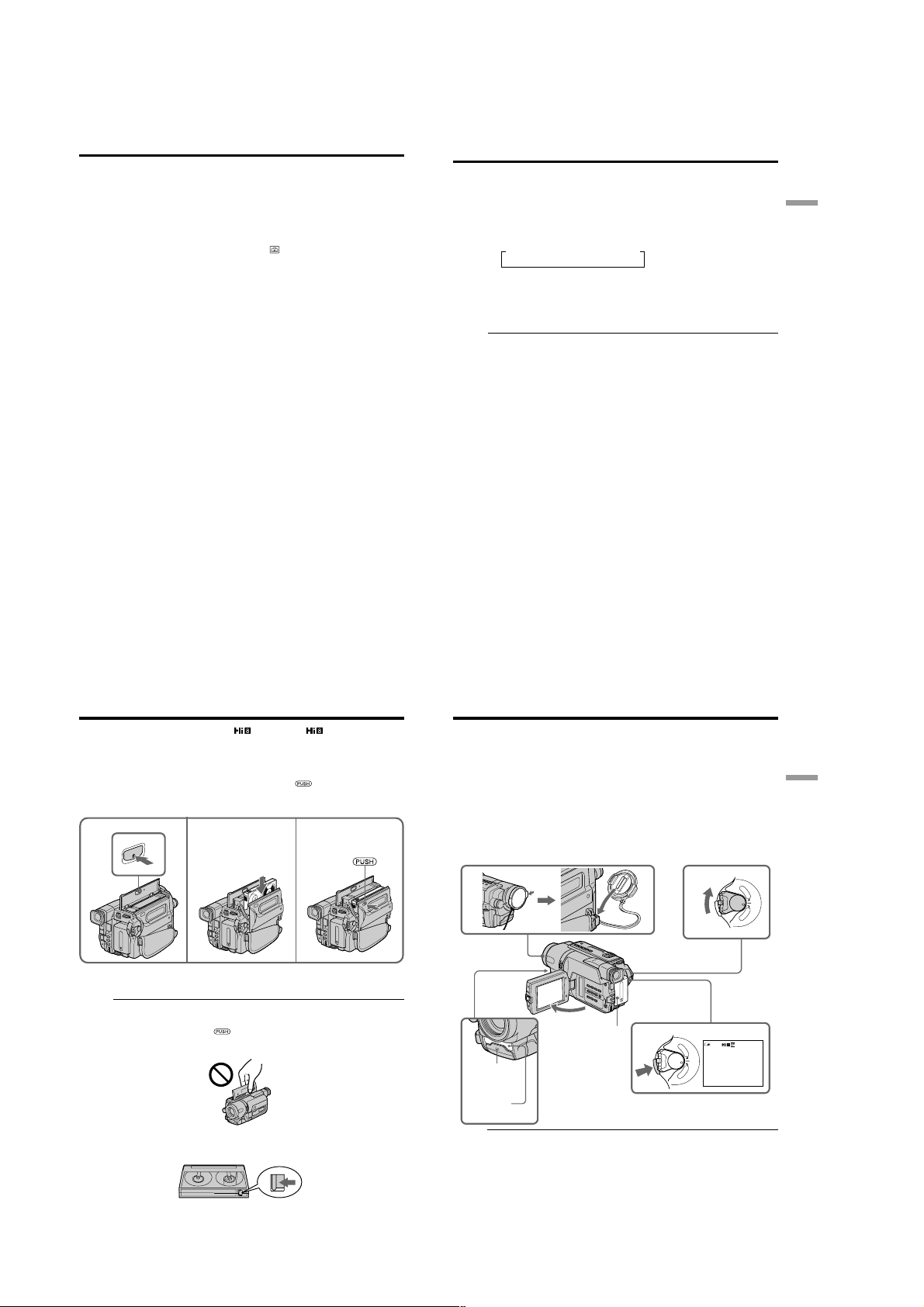
When you want to record in the Hi8 system, use Hi8 video cassettes.
(1) Prepare the power supply (p. 11).
(2) Open the lid of the cassette compartment, and press Z EJECT. The cassette
compartment opens automatically.
(3) Insert a cassette into the cassette compartment with its window facing out and
the write-protect tab on the cassette up.
(4) Close the cassette compartment by pressing the
compartment. The cassette compartment automatically goes down.
(5) Close the lid of the cassette compartment.
2 3
EJECT
To eject a cassette
Follow the procedure above, and eject the cassette in step 3.
Notes
•Do not press the cassette compartment down. Doing so may cause a malfunction.
•The cassette compartment may not be closed when you press any part of the cassette
compartment other than the mark.
•Do not pick up your camcorder by the lid of the cassette compartment.
mark on the cassette
4
— Recording – Basics —
Recording a picture
Your camcorder automatically focuses for you.
(1) Remove the lens cap by pressing both knobs on its sides and attach the lens
cap to the grip strap.
(2) Install the power source and insert a cassette. See “Step 1” to “Step 3” for more
information (p. 11 to 18).
(3) Set the POWER switch to CAMERA while pressing the small green button.
Your camcorder is set to the standby mode.
(4) Open the LCD panel while pressing OPEN. The viewfinder automatically
turns off.
(5) Press START/STOP. Your camcorder starts recording. The REC indicator
appears. The recording lamp located on the front of your camcorder lights up.
To stop recording, press START/STOP again.
The recording lamp lights up in the viewfinder when you record with the
viewfinder.
1
3
4
5
Recording
lamp
2
P
L
A
Y
E
R
O
F
F
POWER
(
C
H
G
C
)
A
M
E
R
A
40min
17
Recording
– Basics
P
L
A
Y
E
R
O
F
F
POWER
(
C
H
G
C
)
A
M
E
R
A
REC
0:00:01
18
To prevent accidental erasure
Slide the write-protect tab on the cassette to expose the red mark.
1-4
Microphone
Notes
•Fasten the grip strap firmly.
•Do not touch the built-in microphone during recording.
Note on Recording mode
Your camcorder records and plays back in the SP (standard play) mode and in the LP
(long play) mode. Select SP or LP in the menu settings (p. 70). In the LP mode, you can
record twice as long as in the SP mode. When you record a tape in the LP mode on your
camcorder, we recommend that you play back the tape on your camcorder.
19
Page 15
CCD-TRV107/TRV108/TRV308/TRV408/TRV608
Recording a picture
To enable smooth transition
You can make the transition between the last scene you recorded and the next scene
smooth as long as you do not eject the cassette even if you turn off your camcorder.
When you change the battery pack, set the POWER switch to OFF (CHG).
If you leave your camcorder in the standby mode for 5 minutes while the cassette
is inserted
Your camcorder automatically turns off. This is to save battery power and to prevent
battery and tape wear. To resume the standby mode for recording, set the POWER
switch to OFF (CHG) once, then turn it to CAMERA, or press START/STOP without
chainging the POWER switch again to start recording. If your camcorder is in the
standby mode, with no cassette inserted, it does not turn off automatically.
When you record in the SP and LP modes on one tape or you record some scenes
in the LP mode
The playback picture may be distorted.
To set the counter to 0:00:00
Press COUNTER RESET (p. 94).
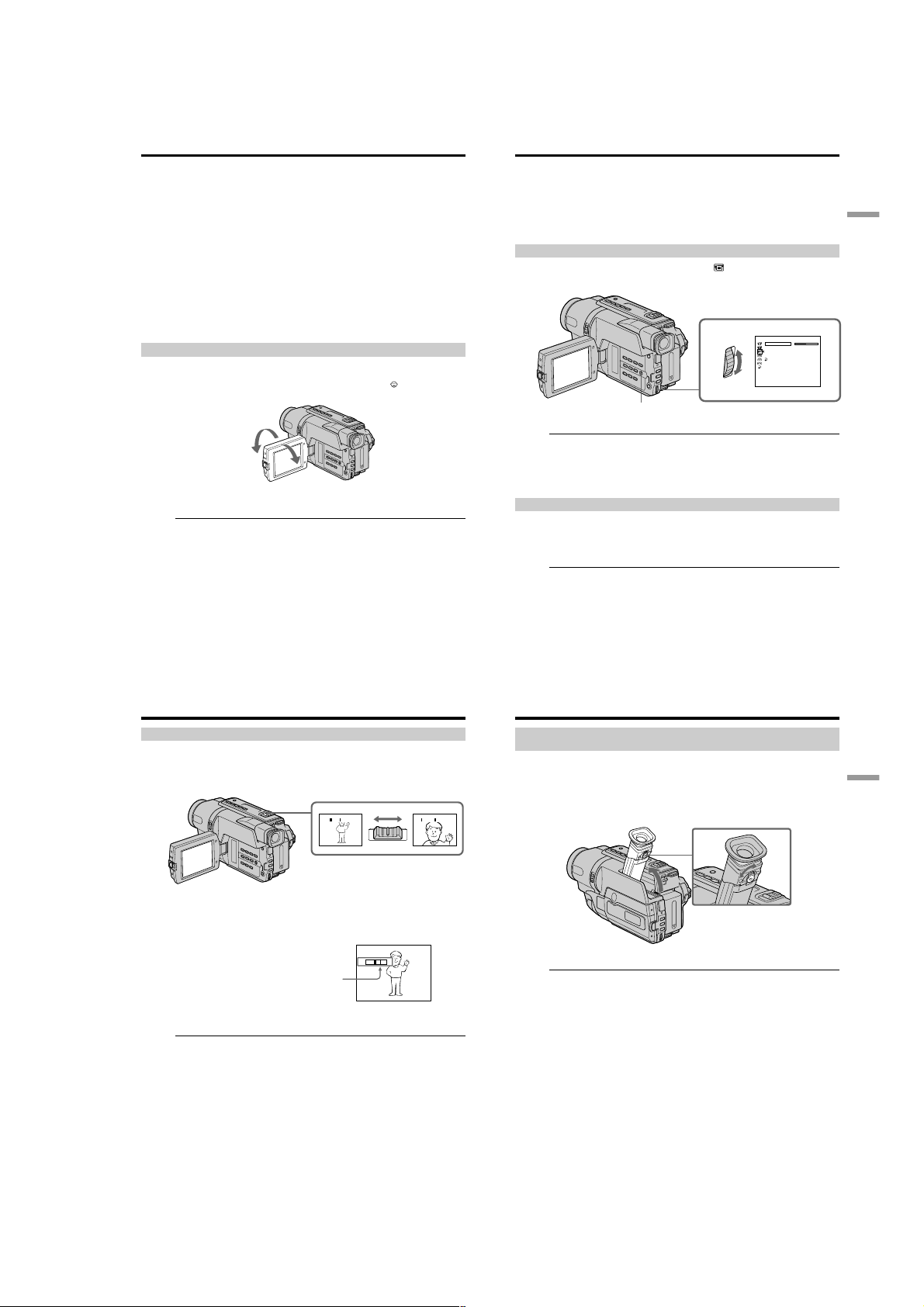
Adjusting the LCD screen
The LCD panel moves about 90 degrees to the viewfinder side and about 180 degrees to
the lens side.
If you turn the LCD panel over so that it faces the other way, the
on the screen (Mirror mode).
When closing the LCD panel, set it vertically until it clicks, and swing it into the
camcorder body.
Note
When using the LCD screen except in the mirror mode, the viewfinder automatically
turns off.
When you use the LCD screen outdoors in direct sunlight
The LCD screen may be difficult to see. If this happens, we recommend that you record
with the viewfinder.
When you adjust angles of the LCD panel
Be sure to open the LCD panel up to 90 degrees.
Picture in the mirror mode
The picture on the LCD screen is a mirror-image. However, the picture will be normal
20
when recorded.
180°
Recording a picture
During recording in the mirror mode
DATE and TIME on your camcorder do not work.
Indicators in the mirror mode
•The STBY indicator appears as Xz and REC as z. Some of other indicators appear
mirror-reversed and others are not displayed.
•The date appears mirror-reversed when the auto date function is working. However,
the date will be normal when recorded.
Adjusting the brightness of the LCD screen
(1) In CAMERA mode, select LCD BRIGHT in in the menu settings (p. 69).
(2) Turn the SEL/PUSH EXEC dial to adjust the brightness of the LCD screen.
1
indicator appears
MENU
LCD screen backlight
You can adjust the brightness of the backlight. Select LCD B.L. in the menu settings
(p. 69).
90°
Even if you adjust the LCD screen backlight
The recorded picture will not be affected.
LCD/VF SET
LCD BRI GHT
LCD B. L.
LCD COLOR
VF B.L.
RETURN
[
] :
MENU
END
Recording
– Basics
After recording
(1) Set the POWER switch to OFF (CHG).
(2) Close the LCD panel.
(3) Eject the cassette.
(4) Attach the lens cap.
After using your camcorder (CCD-TRV107/TRV308/TRV408/TRV608 only)
Remove the battery pack from your camcorder to avoid turning on the built-in light
accidentally.
21
Recording a picture
Using the zoom feature
Move the power zoom lever a little for a slower zoom. Move it further for a faster zoom.
Using the zoom function sparingly results in better-looking recordings.
“T” side: for telephoto (subject appears closer)
“W” side: for wide-angle (subject appears farther away)
W
To use zoom greater than 20×
Zoom greater than 20× is performed digitally. To activate digital zoom, select the digital
zoom power in D ZOOM in the menu settings. The digital zoom function is set to OFF
as a default setting (p. 68).
The picture quality deteriorates as the picture is processed digitally.
The right side of the bar shows the digital
zooming zone.
The digital zooming zone appears when you
select the digital zoom power in D ZOOM in
the menu settings.
Notes on digital zoom
•Digital zoom starts to function when zoom exceeds 20×.
•The picture quality deteriorates as you go toward the “T” side.
When you shoot close to a subject
If you cannot get a sharp focus, move the power zoom lever to the “W” side until the
focus is sharp. You can shoot a subject that is at least about 80 cm (about 2 feet 5/8 in.)
away from the lens surface in the telephoto position, or about 1 cm (about 1/2 in.) away
in the wide-angle position.
WT
T
W
Recording a picture
To record pictures with the viewfinder
– Adjusting the viewfinder
If you record pictures with the LCD panel closed, check the picture with the viewfinder.
Adjust the viewfinder lens to your eyesight so that the indicators in the viewfinder
come into sharp focus.
Lift up the viewfinder and move the viewfinder lens adjustment lever.
W
T
T
Viewfinder backlight (CCD-TRV107/TRV308/TRV408/TRV608 only)
You can change the brightness of the backlight. Select VF B.L. in the menu settings
(p. 69).
Recording
– Basics
22
23
1-5
Page 16
CCD-TRV107/TRV108/TRV308/TRV408/TRV608
Recording a picture
Indicators displayed in the recording mode
The indicators are not recorded on tape.
Remaining battery time indicator
Hi8 format indicator
This appears while playing back or recording in Hi8 format.
Recording mode indicator/Mirror mode indicator
STBY/REC indicator
SP
REC
40
min
Remaining battery time indicator
The remaining battery time indicator indicates the approximate recording time. The
indicator may not be correct, depending on the conditions in which you are recording.
When you close the LCD panel and open it again, it takes about 1 minute for the correct
remaining battery time in minutes to be displayed.
Tape counter indicator
0:00:01
Remaining tape indicator
This appears after you insert a cassette and record
or play back for a while.
Recording a picture
Shooting backlit subjects – BACK LIGHT
When you shoot a subject with the light source behind the subject or a subject with a
light background, use the backlight function.
Press BACK LIGHT in CAMERA mode.
The . indicator appears on the screen.
To cancel, press BACK LIGHT again.
BACK LIGHT
If you press EXPOSURE when shooting backlit subjects
The backlight function will be canceled.
Recording
– Basics
24
Recording a picture
Shooting in the dark – NightShot
The NightShot function enables you to shoot a subject in a dark place. For example, you
can satisfactorily record the environment of nocturnal animals for observation when
you use this function.
While your camcorder is in CAMERA mode, slide NIGHTSHOT to ON.
and “NIGHTSHOT” indicators flash on the screen.
To cancel the NightShot function, slide NIGHTSHOT to OFF.
Using the NightShot Light
The picture will be clearer with the NightShot Light on. To enable the NightShot Light,
set N.S.LIGHT to ON in the menu settings (p. 68).
Notes
•Do not use the NightShot function in bright places (ex. outdoors in the daytime). This
may cause your camcorder to malfunction.
•When you keep NIGHTSHOT setting to ON in normal recording, the picture may be
recorded in incorrect or unnatural colors.
•If focusing is difficult with the autofocus mode when using the NightShot function,
focus manually.
While using the NightShot function, you cannot use the following functions:
– Exposure
– PROGRAM AE
NightShot Light
NightShot Light rays are infrared and so are invisible. The maximum shooting distance
using the NightShot Light is about 3 m (10 feet).
Infrared rays
emitter
ON
OFF
NIGHTSHOT
Recording a picture
Superimposing the date and time on pictures
You can record the date and/or time displayed on the screen superimposed on the
picture.
Carry out the following operations in CAMERA mode.
Press DATE to record the date.
Press TIME to record the time.
Press DATE (or TIME), then press TIME (or DATE) to record the date and time.
Press DATE and/or TIME again. The date and/or time indicator disappears.
DATE TIME
When you purchase your camcorder, the clock setting is set to off. Set the date and time
to your local time before using (p. 16).
Note
The date and time indicators recorded manually cannot be deleted.
If you do not record the date and time in the picture
Record the date and time in the black screen as the background for about 10 seconds,
then erase the date and time indicators before starting actual recording.
25
Recording
– Basics
26
27
1-6
Page 17
Checking the recording – END SEARCH
You can use this button to record a picture from the last recorded scene successively.
END
SEARCH
You can go to the end of the recorded section after you record.
Press END SEARCH in CAMERA mode.
The last 5 seconds of the recorded section are played back and returns to the standby
mode. You can monitor the sound from the speaker.
Notes
•If you start recording after using the end search function, occasionally, the transition
between the last scene you recorded and the next scene may not be smooth.
•Once you eject the cassette after you have recorded on the tape, the end search
function does not work.
CCD-TRV107/TRV108/TRV308/TRV408/TRV608
— Playback – Basics —
Playing back a tape
You can monitor the playback picture on the LCD screen. If you close the LCD panel,
you can monitor the playback picture in the viewfinder.
(1) Install the power source and insert the recorded tape.
(2) Set the POWER switch to PLAYER while pressing the small green button.
(3) Open the LCD panel while pressing OPEN.
(4) Press m to rewind the tape.
(5) Press N to start playback.
(6) To adjust the volume, press either of the two VOLUME buttons. The speaker
on your camcorder is silent when the LCD panel is closed.
You can control playback using the Remote Commander supplied with your
camcorder. (CCD-TRV107/TRV408 only)
P
L
A
Y
E
R
O
F
F
C
ER
H
POW
G
C
)
A
M
E
R
A
6
VOLUME
REW
254
PLAY
Playback – Basics
(
28
Playing back a tape
When monitoring on the LCD screen
You can turn the LCD panel over and move it back to the camcorder body with the
LCD screen facing out [a]. You can adjust the angle of the LCD panel by lifting the LCD
panel up by 7 degrees [b].
[a] [b]
To display the screen indicators – Display function
Press DISPLAY on your camcorder or the Remote Commander (CCD-TRV107/TRV408
only) supplied with your camcorder.
The indicators appear on the screen.
To make the indicators disappear, press DISPLAY again.
DISPLAY
CCD-TRV408
7°
DISPLAY
CCD-TRV408
To stop playback
Press x.
3
1
Playing back a tape
Various playback modes
To operate video control buttons, set the POWER switch to PLAYER.
To view a still image (playback pause)
Press X during playback. To resume playback, press X or N.
To advance the tape
Press M in the stop mode. To resume normal playback, press N.
To rewind the tape
Press m in the stop mode. To resume normal playback, press N.
To locate a scene monitoring the picture (picture search)
Keep pressing m or M during playback. To resume normal playback, release the
button.
To monitor the high-speed picture while advancing or
rewinding the tape (skip scan)
Keep pressing m while rewinding or M while advancing the tape. To resume
rewinding or advancing, release the button.
To view the picture at slow speed (slow playback)
(CCD-TRV107/TRV408 only)
Press y on the Remote Commander during playback. To resume normal playback,
press N.
To search the last scene recorded (END SEARCH)
Press END SEARCH in the stop mode. The last 5 seconds of the recorded section are
played back and the playback stops.
In the various playback modes
Sound is muted.
When the playback pause mode lasts for 5 minutes
Your camcorder automatically enters the stop mode. To resume playback, press N.
If slow playback lasts for about 1 minute (CCD-TRV107/TRV408 only)
Your camcorder automatically returns to normal speed.
When you play back a tape recorded in the LP mode
Noise may appear during playback pause mode, slow playback* or picture search.
When you play back a tape in reverse
Horizontal noise may appear at the center or top and bottom of the screen. This is not a
malfunction.
* CCD-TRV107/TRV408 only
29
Playback – Basics
30
31
1-7
Page 18
CCD-TRV107/TRV108/TRV308/TRV408/TRV608
Viewing the recording on TV
Connect your camcorder to your TV with the A/V connecting cable supplied with your
camcorder to watch the playback picture on the TV screen. You can operate the
playback control buttons in the same way as when you monitor playback pictures on
the LCD screen. We recommend that you power your camcorder from a wall outlet
using the AC power adaptor, when monitoring the playback picture on the TV screen
(p. 15). Refer to the operating instructions of your TV.
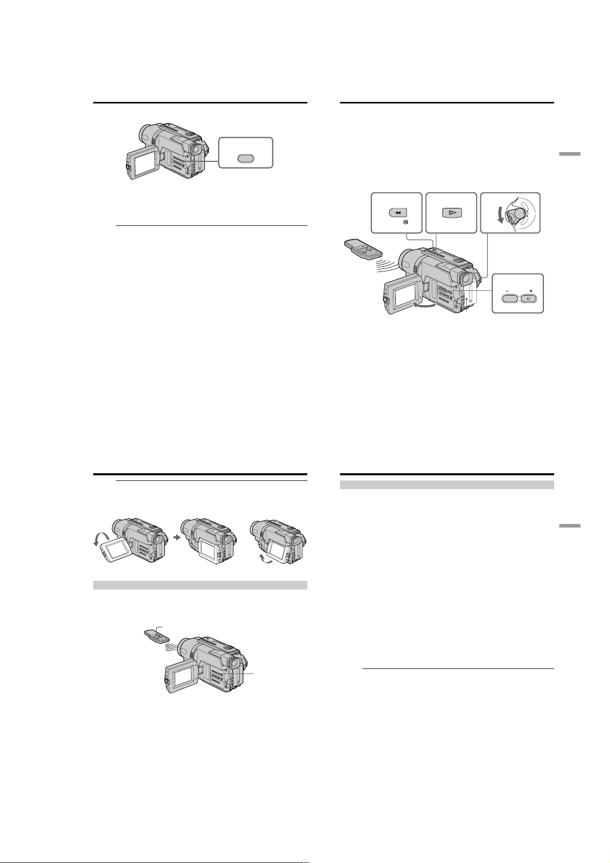
Open the jack cover. Connect your camcorder to the TV using the A/V connecting
cable. Then, set the TV/VCR selector on the TV to VCR.
S VIDEO OUT
V OUT
A/
: Signal flow
A/V connecting cable
(supplied)
If your TV is already connected to a VCR
Connect your camcorder to the LINE IN input on the VCR by using the A/V connecting
cable supplied with your camcorder. Set the input selector on the VCR to LINE.
To connect to a TV without Video/Audio input jacks
Use an NTSC system RFU adaptor (optional). Refer to the operating instructions of your
TV and the RFU adaptor.
If your TV is a stereo type
Connect the audio plug of the A/V connecting cable supplied to the left (white) input
jack of your TV.
If your TV has an S video jack
Connect using an S video cable (optional) to obtain optimum quality screen images.
With this connection, you do not need to connect the yellow (video) plug of the A/V
connecting cable.
Connect an S video cable (optional) to the S video jacks on both your camcorder and the
TV.
To display the screen indicators on TV
Set DISPLAY to V-OUT/LCD in the menu settings (p. 72). Then press DISPLAY on
your camcorder. To turn off the screen indicators, press DISPLAY on your camcorder
again.
32
Yellow
IN
S VIDEO
VIDEO
AUDIO
Black
— Advanced Recording Operations —
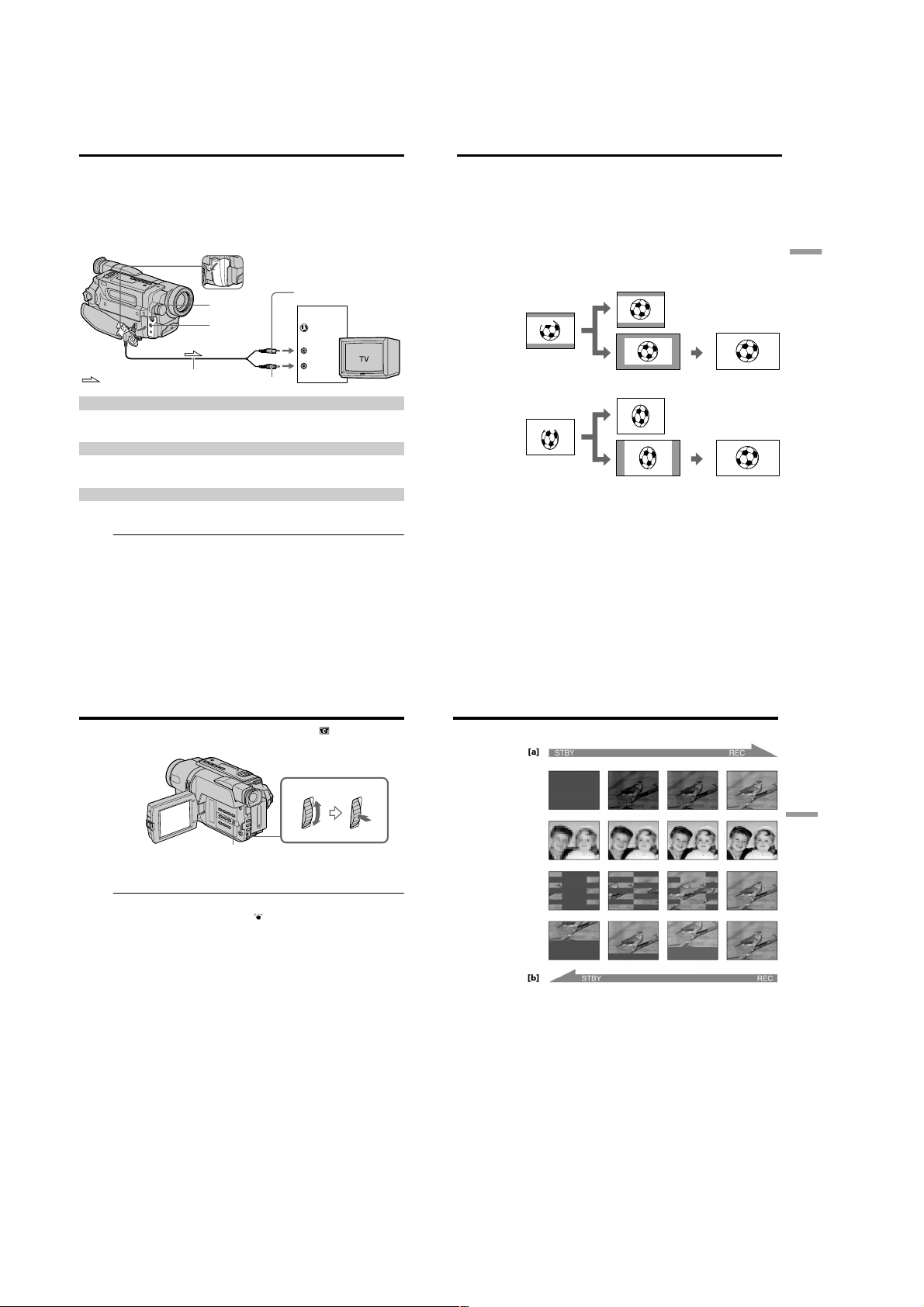
Using the wide mode
You can record a cinema-like picture (CINEMA) or a 16:9 wide picture to watch on the
16:9 wide-screen TV (16:9FULL). Refer to the operating instructions of your TV.
CINEMA
Black bands appear on the screen during recording in the CINEMA mode [a], playing
back on a normal TV [b] or a wide-screen TV [c]. If you set the screen mode of the widescreen TV to the zoom mode, a picture without black bands appears [d].
16:9FULL
The picture during recording in the 16:9FULL mode [e], or playing back on a normal TV
[f] or a wide-screen TV [g] is horizontally compressed. If you set the screen mode of the
wide-screen TV to the full mode, you can watch correctly proportioned images in widescreen format [h].
[b]
CINEMA
CINEMA
[a]
16:9FULL
[e]
[c]
[f]
16:9FULL
[g]
[d]
[h]
Advanced Recording Operations
33
Using the wide mode
In CAMERA mode, set 16:9WIDE to CINEMA or 16:9FULL in in the menu settings
(p. 68).
MENU
To cancel the wide mode
Set 16:9WIDE to OFF in the menu settings.
If the wide mode is set to 16:9FULL (CCD-TRV308/TRV408/TRV608 only)
The SteadyShot function does not work. If you select 16:9FULL in the menu settings
when the SteadyShot function is working, flashes and the SteadyShot function does
not function.
In the wide mode
You cannot select the bounce function with FADER.
Date or time indicator
When you record in the 16:9FULL mode, the date or time indicator will be widened on
wide-screen TVs.
During recording
You cannot select or cancel the wide mode. When you cancel the wide mode, set your
camcorder to the standby mode and then set 16:9WIDE to OFF in the menu settings.
Using the fader function
You can fade in or out to give your recording a professional appearance.
FADER
M.FADER
(mosaic)
STRIPE
BOUNCE
(Fade in only)
MONOTONE
When fading in, the picture gradually changes from black-and-white to color.
When fading out, the picture gradually changes from color to black-and-white.
Advanced Recording Operations
34
35
1-8
Page 19
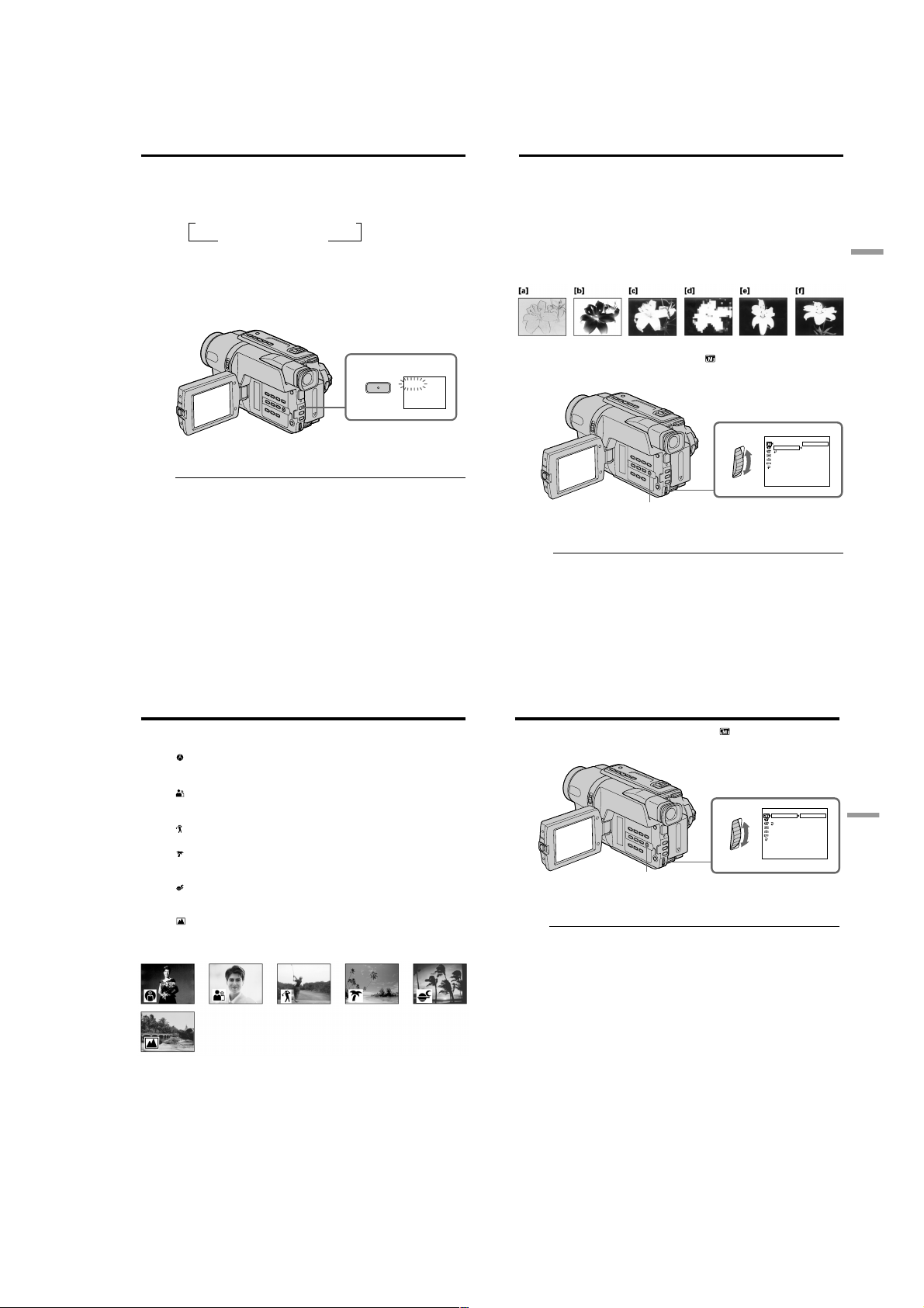
CCD-TRV107/TRV108/TRV308/TRV408/TRV608
Using the fader function
(1) When fading in [a]
In the standby mode, press FADER until the desired fader indicator flashes.
When fading out [b]
In the recording mode, press FADER until the desired fader indicator flashes.
The indicator changes as follows:
t FADER t M.FADER t STRIPE t BOUNCE*
no indicator T MONOTONE T
The last selected fader mode is indicated first of all.
* Fade in only
(2) Press START/STOP. The fader indicator stops flashing.
After the fade in/out is carried out, your camcorder automatically returns to
the normal mode.
To cancel the fader function
Before pressing START/STOP, press FADER until the indicator disappears.
The date, time indicator and title do not fade in or fade out
Erase them before operating the fader function if they are not needed.
While using the bounce function, you cannot use the following functions:
– Focus
– Zoom
– Picture effect
Note on the bounce function
The BOUNCE indicator does not appear in the following mode or functions:
– D ZOOM is activated in the menu settings
– Wide mode
– Picture effect
– PROGRAM AE
Using special effects – Picture effect
You can digitally process images to obtain special effects like those in films or on the
TV.
PASTEL [a] : The contrast of the picture is emphasized, and the picture looks like an
NEG.ART [b] : The color and brightness of the picture are reversed.
SEPIA : The picture is sepia.
B&W : The picture is monochrome (black-and-white).
SOLARIZE [c] : The light intensity is clearer, and the picture looks like an illustration.
MOSAIC [d] : The picture is mosaic.
SLIM [e] : The picture expands vertically.
STRETCH [f] : The picture expands horizontally.
1
FADER
FADER
(1) In CAMERA mode, select P EFFECT in in the menu settings (p. 68).
(2) Select the desired picture effect mode in the menu settings, then press the SEL/
To cancel the picture effect function
Set P EFFECT to OFF in the menu settings.
When you set the POWER switch to OFF (CHG)
Your camcorder automatically returns to the normal mode.
animated cartoon.
PUSH EXEC dial.
MENU
Advanced Recording Operations
1
MANUA L S ET
PROGRAM AE
P EFFECT
RETURN
[
] :
MENU
END
OFF
PASTEL
.
NEGART
SEPI A
B&
W
SOLAR I ZE
MOSA I C
SLIM
STRETCH
36
Using the PROGRAM AE function
You can select the PROGRAM AE (Auto Exposure) mode to suit your specific shooting
requirements.
SPOTLIGHT (Spotlight)
This mode prevents people’s faces, for example, from appearing excessively white
when shooting subjects lit by strong light in the theater.
PORTRAIT (Soft portrait)
This mode brings out the subject while creating a soft background for subjects such as
people or flowers.
SPORTS (Sports lesson)
This mode minimizes shake on fast-moving subjects such as in tennis or golf.
BEACH&SKI (Beach & ski)
This mode prevents people’s faces from appearing dark in strong light or reflected light,
such as at a beach in midsummer or on a ski slope.
SUNSETMOON (Sunset & moon)
This mode allows you to maintain atmosphere when you are recording sunsets, general
night views, fireworks displays and neon signs.
LANDSCAPE (Landscape)
This mode is for when you are recording distant subjects such as mountains and
prevents your camcorder from focusing on glass or metal mesh in windows when you
are recording a subject behind glass or a screen.
Using the PROGRAM AE function
(1) In CAMERA mode, select PROGRAM AE in in the menu settings (p. 68).
(2) Select the desired PROGRAM AE mode in the menu settings, then press the
SEL/PUSH EXEC dial.
1
MENU
To cancel the PROGRAM AE function
Set PROGRAM AE to AUTO in the menu settings.
Notes
•In the spotlight, sports lesson and beach & ski modes, you cannot take close-ups. This
is because your camcorder is set to focus only on subjects in the middle to far distance.
•In the sunset & moon and landscape modes, your camcorder is set to focus only on
distant subjects.
•While using the PROGRAM AE function, you cannot select the bounce function with
FADER.
•While setting NIGHTSHOT to ON, the PROGRAM AE function does not work. (The
indicator flashes.)
Even if the PROGRAM AE function is selected
You can adjust the exposure manually.
If you are recording under a discharge tube such as a fluorescent lamp, sodium
lamp or mercury lamp
Flickering or changes in color may occur in the following modes. If this happens, turn
the PROGRAM AE function off:
– Soft portrait mode
– Sports lesson mode
MANUAL SET
PROGRAM AE
P EFFECT
RETURN
[
] :
MENU
END
AUTO
SPOTLI GHT
PORTRAIT
SPORTS
BEACH&SKI
SUNSETMOON
LANDSCAPE
37
Advanced Recording Operations
38
39
1-9
Page 20
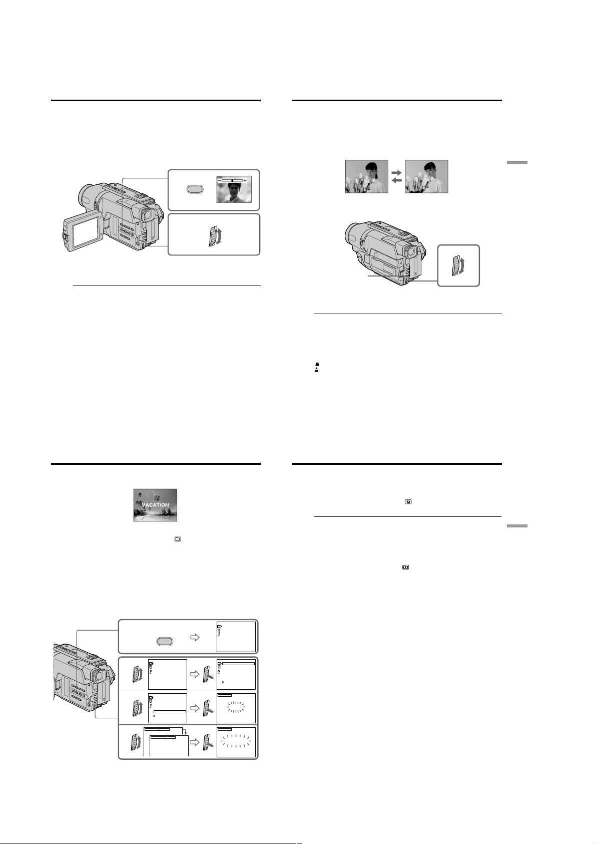
CCD-TRV107/TRV108/TRV308/TRV408/TRV608
Adjusting the exposure manually
You can manually adjust and set the exposure.
Adjust the exposure manually in the following cases:
– The subject is backlit
– Bright subject and dark background
– To record dark pictures (e.g. night scenes) faithfully
(1) In CAMERA mode, press EXPOSURE.
The exposure indicator appears on the screen.
(2) Turn the SEL/PUSH EXEC dial to adjust the brightness.
1
EXPOSURE
2
To return to the automatic exposure mode
Press EXPOSURE.
Note
When you adjust the exposure manually, the backlight function does not work in
CAMERA mode.
Your camcorder automatically returns to the automatic exposure mode:
– if you change the PROGRAM AE mode
– if you slide NIGHTSHOT to ON
Focusing manually
You can gain better results by manually adjusting the focus in the following cases:
•The autofocus mode is not effective when shooting:
– subjects through glass coated with water droplets.
– horizontal stripes.
– subjects with little contrast with backgrounds such as walls and sky.
•When you want to change the focus from a subject in the foreground to a subject in the
background.
•Shooting a stationary subject when using a tripod.
(1) In CAMERA mode, press FOCUS. The 9 indicator appears on the screen.
(2) Turn the SEL/PUSH EXEC dial to sharpen focus.
FOCUS
To return to the autofocus mode
Press FOCUS.
To focus precisely
Adjust the zoom by first focusing at the “T” (telephoto) position and then shooting at
the “W” (wide-angle) position. This makes focusing easier.
When you shoot close to the subject
Focus at the end of the “W” (wide-angle) position.
9 changes to the following indicators:
when recording a distant subject.
when the subject is too close to focus on.
Advanced Recording Operations
40
Superimposing a title
You can select one of eight preset titles and two custom titles (p. 44). You can also select
the language, color, size, and position of titles.
(1) In CAMERA mode, press TITLE to display the title menu.
(2) Turn the SEL/PUSH EXEC dial to select
(3) Select the desired title in the menu settings, then press the SEL/PUSH EXEC
dial. The titles are displayed in the language you selected.
(4) Change the color, size, or position, if necessary.
1 Turn the SEL/PUSH EXEC dial to select the color, size, or position, then
press the dial. The item appears.
2 Turn the SEL/PUSH EXEC dial to select the desired item, then press the
dial.
3 Repeat steps 1 and 2 until the title is laid out as desired.
(5) Press the SEL/PUSH EXEC dial again to complete the setting.
(6) Press START/STOP to start recording.
(7) When you want to stop recording the title, press TITLE.
41
Superimposing a title
To superimpose the title while you are recording
Press TITLE while you are recording, and carry out steps 2 to 5. When you press the
SEL/PUSH EXEC dial at step 5, the title is superimposed.
To select the language of a preset title
If you want to change the language, select before step 2. Then select the desired
language and return to step 2.
Note
Both the date and time or either of them may not be displayed depending on the size or
, and then press the dial.
PRESET TI TLE
!
HELLO
1
2
3
4
T I TLE
PRESET TI TLE
HELLO
HAPPY B IRT HDAY
HAPPY HOL IDAY S
CONGRATU LAT I ONS
OUR SWEET BABY
W
EDDI NG
VACATI ON
THE END
[
TITLE]:END
PRESET TI TLE
HELLO
HAPPY B IRT HDAY
HAPPY HOL IDAY S
CONGRATU LAT I ONS
OUR SWEET BABY
W
EDDI NG
VACATI ON
THE END
RETURN
[
TITLE]:END
SIZE SMALL
SIZE LARGE
!
!
!
!
VACATION
HAPPY B IRTHDAY
HAPPY HOLI DAYS
CONGRATU LAT I ONS
OUR SWEET BABY
W
EDDI NG
VACATI ON
THE END
[
TITLE]:END
PRESET T ITL E
!
HELLO
HAPPY B IRT HDAY
HAPPY HOLI DAYS
CONGRATU LAT I ONS
OUR SWEET BABY
W
EDDI NG
VACATI ON
THE END
RETURN
[
TITLE]:END
TITLE
VACATION
[
TITLE]:END
TITLE
VACATION
[
TITLE]:END
!
!
position of the title.
If you display the menu or title menu while superimposing a title
The title is not recorded while the menu or title menu is displayed.
To use the custom title
If you want to use the custom title, select in step 2.
Title setting
•The title color changes as follows:
WHITE y YELLOW y VIOLET y RED y CYAN y GREEN y BLUE
•The title size changes as follows:
SMALL y LARGE
You cannot input 13 characters or more in LARGE size. If you input more than 12
characters, the title size returns to SMALL even if you select LARGE.
•The title position changes as follows:
1y 2y 3y 4y 5y 6y 7y 8y 9
The larger the position number, the lower the title is positioned.
When you select the title size “LARGE,” you cannot choose position 9.
When you select the title size “LARGE” in the CINEMA mode, you cannot choose
position 8 nor 9.
When you are selecting and setting the title
You cannot record the title displayed on the screen.
When you superimpose a title while you are recording
The beep does not sound.
While you are playing back
You can superimpose a title. However, the title is not recorded on tape.
You can record a title when you dub a tape connecting your camcorder to the VCR with
the A/V connecting cable.
Advanced Recording Operations
42
43
1-10
Page 21
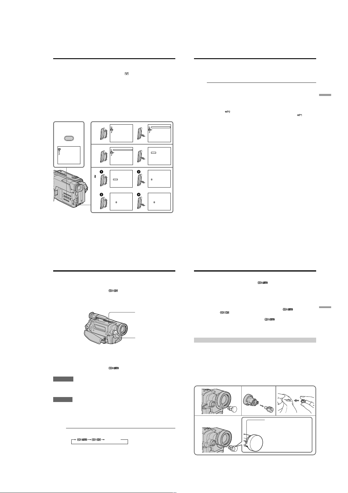
CCD-TRV107/TRV108/TRV308/TRV408/TRV608
Making your own titles
You can make up to two titles and store them in your camcorder. Each title can have up
to 20 characters.
(1) In CAMERA or PLAYER mode, press TITLE.
(2) Turn the SEL/PUSH EXEC dial to select
(3) Turn the SEL/PUSH EXEC dial to select the first line (CUSTOM1 SET) or the
second line (CUSTOM2 SET), then press the dial.
(4) Turn the SEL/PUSH EXEC dial to select the column of the desired character,
then press the dial.
(5) Turn the SEL/PUSH EXEC dial to select the desired character, then press the
dial.
(6) Repeat steps 4 and 5 until you have selected all characters and completed the
title.
(7) To finish making your own titles, turn the SEL/PUSH EXEC dial to select
[SET], then press the dial. The title is stored in memory.
(8) Press TITLE to make the title menu disappear.
1
2
T I TLE
PRESET T ITL E
HELLO
!
HAPPY B IRTHDAY
HAPPY HOLI DAYS
CONGRATU LAT I ONS
OUR SWEET BABY
W
EDDI NG
VACATI ON
THE END
[
TITLE]:END
!
3
4
6
TITLE SET
CUSTOM1 SET
CUSTOM2 SET
[
TITLE]:END
TITLE SET
CUSTOM1 SET
CUSTOM2 SET
RETURN
[
TITLE]:END
P1
TITLE SET
____________________
12345
ABCDE
$F¥DM£
¿
:
FGHI J
67890
iø”
]
[
KLMNO
ÀÈÌ ÒÙ
C
]
[
c
P2
ÁÉÍ ÓÚ
PQRST
]
[
ƌ
SET
ÂÊÎ
UV
W
XY
ГХСзЯ
Z
&?!
ДПЦЬЕ
’ .,/–
[
TITLE]:END
P1
TITLE SET
____________________
12345
ABCDE
DM
£
$F¥
¿
:
67890
FGHI J
iø”
[
]
KLMNO
ÀÈÌ ÒÙ
C
]
[
c
P2
ÁÉÍ ÓÚ
PQRST
]
[
ƌ
SET
ÂÊÎ
UV
W
XY
ГХСзЯ
Z
&?!
ДПЦЬЕ
’ .,/–
[
TITLE]:END
, then press the dial.
TITLE SET
CUSTOM1 SET
CUSTOM2 SET
RETURN
[
TITLE]:END
TITLE SET
P1
____________________
ABCDE
DM
£
12345
$F¥
¿
:
67890
FGHI J
iø”
[
]
KLMNO
ÀÈÌ ÒÙ
C
[
]
c
P2
ÁÉÍ ÓÚ
PQRST
]
[
ƌ
SET
ÂÊÎ
UV
W
XY
ГХСзЯ
&?!
Z
ДПЦЬЕ
’ .,/–
[
TITLE]:END
TITLE• SET
P1
____________________
12345
ABCDE
$F¥DM£
¿
:
67890
FGHI J
iø”
]
[
KLMNO
ÀÈÌ ÒÙ
C
]
[
c
P2
ÁÉÍ ÓÚ
PQRST
]
[
ƌ
SET
ÂÊÎ
UV
W
XY
ГХСзЯ
&?!
Z
ДПЦЬЕ
’ .,/–
[
TITLE]:END
TITLE SET
P1
S
___________________
12345
ABCDE
$F¥DM£
¿
:
67890
FGHI J
iø”
]
[
KLMNO
ÀÈÌ ÒÙ
C
[
]
c
P2
ÁÉÍ ÓÚ
PQRST
[
]
ƌ
SET
ÂÊÎ
UV
W
XY
ГХСзЯ
Z
&?!
ДПЦЬЕ
’ .,/–
[
TITLE]:END
Making your own titles
To change a title you have stored
In step 3, select CUSTOM1 SET or CUSTOM2 SET, depending on which title you want
to change, then press the SEL/PUSH EXEC dial. Turn the SEL/PUSH EXEC dial to
select [C], then press the dial to delete the title. The last character is erased. Enter the
new title as desired.
If you take 5 minutes or longer to enter characters in the standby mode while a
cassette is in your camcorder
The power automatically turns off. The characters you have entered remain stored in
memory. Set the POWER switch to OFF (CHG) once, and turn it to CAMERA again,
then proceed from step 1.
We recommend setting the POWER switch to PLAYER or removing the cassette so that
your camcorder does not automatically turn off while you are entering title characters.
If you select [
The menu for selecting alphabet and Russian characters appears. Select [
to the previous screen.
To erase a character
Select [C]. The last character is erased.
To enter a space
Select [Z& ?!], then select the blank part.
]
Advanced Recording Operations
] to return
44
Using the built-in light
– CCD-TRV107/TRV308/TRV408/TRV608 only
You can use the built-in light to suit your shooting situation. The recommended
distance between the subject and camcorder is about 1.5 m (5 feet).
Press LIGHT repeatedly, until the indicator appears on the screen while your
camcorder is in CAMERA mode. The built-in light turns on.
If you turn the POWER switch to OFF (CHG), the built-in light turns off
simultaneously. You cannot turn the built-in light on by turning the POWER switch to
CAMERA again. To turn on the built-in light again, press LIGHT again in CAMERA
mode.
To turn off the built-in light
Press LIGHT repeatedly, until no indicator appears on the screen.
To turn on the built-in light automatically
Press LIGHT repeatedly, until the indicator appears on the screen.
The built-in light automatically turns on and off according to the ambient brightness.
CAUTION
Be careful not to touch the lighting section, because the plastic window and
surrounding surfaces are hot while the light is on. It remains hot for a while after
the light is turned off.
DANGER
Not to be handled by children.
Emits intense heat and light.
Use with caution to reduce the risk of fire or injury to persons.
Do not directly aim the light at persons or materials from less than 1.22 m (4 feet)
during use and until cool.
Turn the built-in light off when not in use.
When you press LIGHT
The indicator changes as follows:
no indicator
LIGHT
Built-in light
Using the built-in light
Notes
•The built-in light turns off automatically in the following cases:
– When it stays on in the AUTO mode ( ) for more than 5 minutes.
– When you leave it on for more than 5 minutes with no cassette inserted or after the
tape has run out.
To turn the built-in light on again, press LIGHT again.
•The battery pack discharges quickly while the built-in light is turned on. Turn it off
when not in use.
•When you do not use your camcorder, turn the built-in light off and remove the
battery pack to avoid turning on the built-in light accidentally.
•When flickering occurs while shooting in the AUTO mode ( ), press LIGHT
until the indicator appears.
•The built-in light may turn on/off when you use the PROGRAM AE or backlight
function while shooting in the AUTO mode ( ).
•The built-in light may turn off when inserting or ejecting a cassette.
•While the end search function is working, the built-in light is turned off.
•When you use the conversion lens (optional), the built-in light is blocked and may not
illuminate the subject properly.
Replacing the bulb
Use the Sony XB-3D halogen lamp (optional). The supplied halogen lamp is not
commercially available. Purchase the Sony XB-3D halogen lamp.
Remove the power source before replacing the bulb.
(1) Remove the built-in light unit while pushing the hole under the built-in light
unit using a wire.
(2) Turn the bulb housing counterclockwise and detach from the built-in light
unit.
(3) Replace the bulb using a dry cloth.
(4) Attach the bulb housing by turning it clockwise, then replace the built-in light
unit.
1
4
23
Note
Be sure to align the
tab with the groove
when inserting.
45
Advanced Recording Operations
46
47
1-11
Page 22
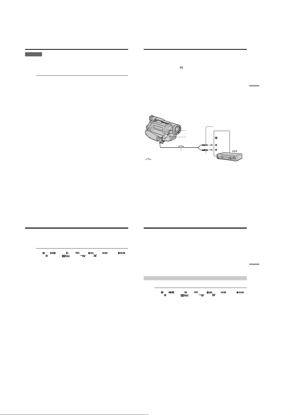
CCD-TRV107/TRV108/TRV308/TRV408/TRV608
Using the built-in light
CAUTION
•When replacing the bulb, use only the Sony XB-3D halogen lamp (optional) to reduce
the risk of fire.
•To prevent possible burn hazard, disconnect the power source before replacing and
do not touch the bulb until the bulb becomes cool enough to handle (for about 30
minutes or more).
Note
To prevent the bulb from being smudged with finger prints, handle it with a dry cloth,
etc. If the bulb is smudged, wipe it completely.
— Editing —
Dubbing a tape
Using the A/V connecting cable
Connect your camcorder to the VCR using the A/V connecting cable supplied with
your camcorder.
You can record and edit a picture with the connected VCR by using your camcorder as
a player.
Set DISPLAY to LCD in
If you do not make the indicators disappear, they are recorded on tapes.
Make the indicators disappear by pressing the following buttons:
– DISPLAY on your camcorder
– DISPLAY on the Remote Commander (CCD-TRV107/TRV408 only)
(1) Insert a blank tape (or a tape you want to record over) into the VCR, and insert
the recorded tape into your camcorder.
(2) Set the input selector on the VCR to LINE. Refer to the operating instructions
of your VCR for more information.
(3) Set the POWER switch to PLAYER.
(4) Play back the recorded tape on your camcorder.
(5) Start recording on the VCR.
Refer to the operating instructions of your VCR for more information.
in the menu settings (The default setting is set to LCD.)
Editing
48
Dubbing a tape
When you have finished dubbing a tape
Press x on both your camcorder and the VCR.
To prevent deterioration of pictures when dubbing
Set EDIT to ON in the menu settings before dubbing.
You can edit on VCRs that support the following systems:
8 mm , Hi8 , Digital 8 , VHS , S-VHS , VHSC , S-VHSC ,
Betamax , ED Betamax , mini DV , or DV
If your VCR is a stereo type
Connect the audio plug of the A/V connecting cable supplied to the left (white) input
jack of your VCR.
If your VCR has an S video jack
Connect using an S video cable (optional) to obtain optimum quality screen images.
With this connection, you do not need to connect the yellow (video) plug of the A/V
connecting cable.
Connect an S video cable (optional) to the S video jacks of both your camcorder and the
VCR.
Yellow
IN
S VIDEO
VIDEO
AUDIO
Black
: Signal flow
S VIDEO OUT
A
A/V connecting cable
(supplied)
/
V OUT
Dubbing a tape easily – Easy Dubbing
VCR operation for dubbing can be controlled easily by using your camcorder when the
VCR is connected.
You can select one of eight preset titles and two custom titles stored in your camcorder
as instructed in “Making your own titles” (p. 44). Select the desired color, size, and
background color of titles.
Using the Easy Dubbing function
Step 1 Connecting the VCR (p. 51).
Step 2 Setting the VCR to operate with your camcorder (p. 52 to 55).
Step 3 Selecting the title (p. 56).
Step 4 Selecting the dubbing mode (p. 57).
Step 5 Performing Easy Dubbing (p. 58).
If you dub using the same VCR again, you can skip step 2.
If you do not need to put in a title, you can skip step 3.
Step 1: Connecting the VCR
Connect the devices as illustrated in page 49.
You can edit on VCRs that support the following systems:
8 mm , Hi8 , Digital 8 , VHS , S-VHS , VHSC , S-VHSC ,
Betamax , ED Betamax , mini DV , or DV
If your VCR has an S video jack
Connect using an S video cable (optional) to obtain optimum quality screen images.
With this connection, you do not need to connect the yellow (video) plug of the A/V
connecting cable.
Connect an S video cable (optional) to the S video jacks of both your camcorder and the
VCR.
49
Editing
50
51
1-12
Page 23
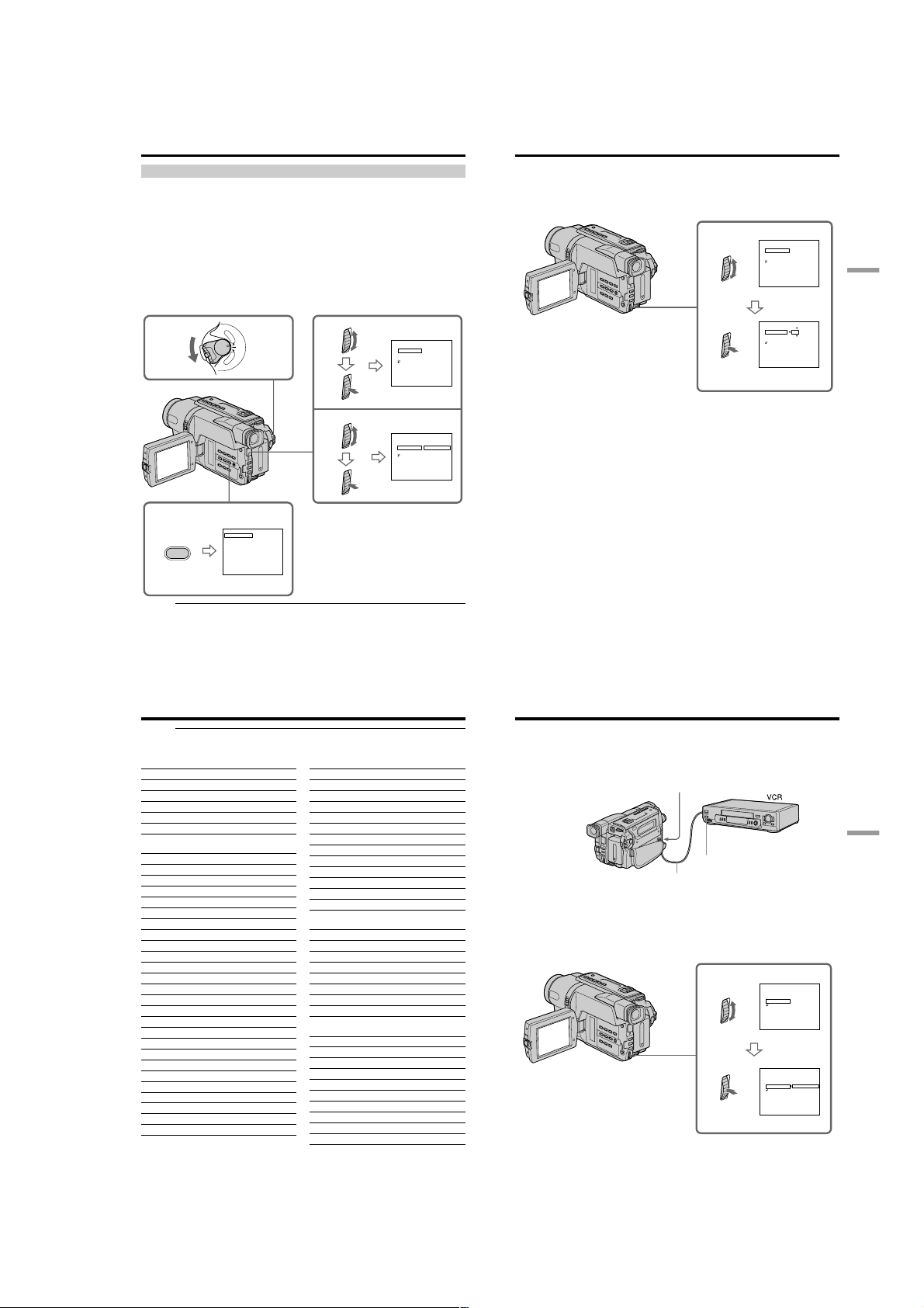
CCD-TRV107/TRV108/TRV308/TRV408/TRV608
Dubbing a tape easily – Easy Dubbing
Step 2: Setting the VCR to operate with your camcorder
You can control the VCR by wireless remote control.
(1) Setting the modes to cancel recording pause on the VCR
1 Set the POWER switch to PLAYER on your camcorder.
2 Turn the power of the connected VCR on, then set the input selector to
LINE.
When you connect a video camera recorder, set its power switch to VTR/VCR.
3 Press EASY DUBBING to display the menu.
4 Turn the SEL/PUSH EXEC dial to select SETUP, then press the dial.
5 Turn the SEL/PUSH EXEC dial to select PAUSE MODE, then press the
dial.
6 Turn the SEL/PUSH EXEC dial to select the mode to cancel recording
pause on the VCR, then press the dial.
1
P
L
A
Y
E
R
O
F
F
(
C
R
E
W
H
O
P
G
C
)
A
M
E
R
A
4
5
3
EASY DUBBING
EASY DUBBING
START
TI TLE SEL
MODE SEL
SETUP
[
EASY DUB]:END
00:00:0
NORMAL
EASY DUBBING
SETUP
I R SETUP
PAUSE MODE
I R TEST
RETURN
[
EASY DUB]:END
EASY DUBBING
SETUP
I R SETUP
PAUSE MODE
IR TEST
RETURN
[
EASY DUB]:END
b
PAUSE
REC
PB
Dubbing a tape easily – Easy Dubbing
(2) Setting the IR SETUP code
1 Turn the SEL/PUSH EXEC dial to select IR SETUP, then press the dial.
2 Turn the SEL/PUSH EXEC dial to select the IR SETUP code of your VCR,
then press the dial.
Check the code in “About the IR SETUP code” (p. 54).
1
00:00:0
3
NORMAL
00:00:0
NORMAL
EASY DUBBING
SETUP
I R SETUP
PAUSE MODE
IR TEST
RETURN
[
EA Y D U B ] S :END
EASY DUBBING
SETUP
I R SETUP
PAUSE MODE
I R TEST
RETURN
[
EA Y D U B ] S :END
00:00:0
3
NORMAL
Editing
00:00:0
3
NORMAL
Buttons for canceling recording pause on the VCR
The buttons vary depending on your VCR. To cancel recording pause:
– Select PAUSE if the button to cancel recording pause is X.
– Select REC if the button to cancel recording pause is z.
52
– Select PB if the button to cancel recording pause is N.
Dubbing a tape easily – Easy Dubbing
About the IR SETUP code
The IR SETUP code is stored in the memory of your camcorder. Be sure to set the
correct code depending on your VCR. The default setting is Code number 3.
Brand IR SETUP code
Sony 1, 2, 3, 4, 5, 6
Admiral (M. Wards) 89
Aiwa 80, 47, 54
Akai 49, 51
Audio Dynamic 21, 35
Bell&Howell (M. Wards)
Brocsonic 70, 82, 21
Canon 77, 78
Citizen 47
Craig 73, 47
Curtis Mathis 8, 80, 77
Daewoo 26, 40, 77
DBX 21, 33, 35
Dimensia 8
Emerson 26, 82, 59, 48, 70, 81, 80
Fisher 36, 45, 37, 44
Funai 80
General Electric 8, 77, 32*, 94*, 101
Goldstar/LG 47
GO VIDEO 71
Hitachi 78, 8, 42
HQ 40
Instant Replay 77, 78
JC Penny 77, 42, 8, 36, 21, 33, 35
JVC 21, 12, 13, 14, 33, 35
Kenwood 21, 33, 47, 35
LXI (Sears) 80, 47, 42, 44, 45, 36, 37, 49
Magnavox 83, 78, 77, 17
Marantz 21, 33, 35
Marta 47
Memorex 77, 37
Minolta 42, 8
36
* TV/VCR component
Note on IR SETUP code
The Easy Dubbing is not possible if the VCR does not support IR SETUP codes.
54
Brand IR SETUP code
Mitsubishi/MGA 28, 22, 23, 24, 29
Multitech 23, 80, 32
NEC 21, 33, 35
Olympic 77, 78
Optimus 22
Orion 60
Panasonic 16, 17, 78, 77
Pentax 42, 8
Philco 78, 77, 26, 70
Philips 47, 83, 78, 77
Pioneer 78
Quasar 78, 77, 16, 17, 6
RCA/PROSCAN
Realistic 77, 36, 88, 37, 22, 80
Sansui 21
Singer 73
Samsung 94, 41, 32, 24, 32*, 94*, 24*
Sanyo 36, 37, 26, 36, 47
Scott 40, 41, 32, 37, 28, 22, 23, 24
Sharp 89, 88
Shintom 73
Signature 2000 (M. Wards)
Sylvania 83, 78, 77, 80
Symphonic 80
Tashiro 47
Tatung 21, 33, 35
Teac 21, 33, 80, 35
Technics 77, 78
Toshiba 40, 7, 49
Wards 89, 88, 37, 95, 47
Yamaha 36, 21, 33, 35
Zenith 95
8, 42, 16, 77, 83, 7, 40, 41, 78, 78*,
101
80, 89
Dubbing a tape easily – Easy Dubbing
(3) Setting your camcorder and the VCR to face each other
Locate the Infrared rays emitter of your camcorder and face it towards the remote
sensor of the VCR.
Set the devices about 30 cm (12 in.) apart, and remove any obstacles between the
devices.
Infrared rays emitter
Remote sensor
A/V connecting cable (supplied)
(4) Confirming the VCR operation
1 Insert a recordable tape into the VCR, then set to recording pause.
2 Turn the SEL/PUSH EXEC dial to select IR TEST, then press the dial.
3 Turn the SEL/PUSH EXEC dial to select EXECUTE, then press the dial.
If the VCR starts recording, the setting is correct.
When finished, the indicator changes to COMPLETE.
2
When the VCR does not operate correctly
•After checking the code in “About the IR SETUP code,” set IR SETUP or
PAUSE MODE again.
•Place your camcorder at least 30 cm (12 in.) away from the VCR.
•Refer to the operating instructions of your VCR.
EASY DUBBING
SETUP
I R SETUP
PAUSE MODE
I R TEST
RETURN
[
EASY DUB]:END
EASY DUBBING
SETUP
I R SETUP
PAUSE MODE
I R TEST
RETURN
[
EASY DUB]:END
READY
NORMAL
ENGAGE
REC PAUSE
RETURN
EXECUTE
NORMAL
53
Editing
00:00:0
00:00:0
55
1-13
Page 24
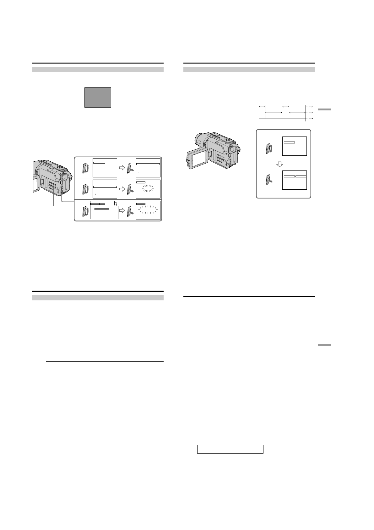
CCD-TRV107/TRV108/TRV308/TRV408/TRV608
Dubbing a tape easily – Easy Dubbing
Step 3: Selecting the title
You can select title, color, size, and background color.
CUSTOM1 and CUSTOM2 are custom titles stored in your camcorder as instructed in
“Making your own titles” (p. 44).
(1) Press EASY DUBBING to display the menu.
(2) Turn the SEL/PUSH EXEC dial to select TITLE SEL, then press the dial.
(3) Select the desired title in the menu settings, then press the dial. The title is
displayed.
(4) Change the color, size, or background color, if necessary.
1 Turn the SEL/PUSH EXEC dial to select the color, size, or background
color, then press the dial. The item appears.
2 Turn the SEL/PUSH EXEC dial to select the desired item, then press the
dial.
3 Repeat steps 1 and 2 until the title is laid out as desired.
4 Press the SEL/PUSH EXEC dial again to complete the setting.
1
2
3
56
EASY DUBBING
Note
You can put a title only into the tape of the VCR.
Title setting
•The title color changes as follows:
WHITE y YELLOW y VIOLET y RED y CYAN y GREEN y BLUE
•The title size changes as follows:
SMALL y LARGE
•The background color changes as follows:
FADE y WHITE y YELLOW y VIOLET y RED y CYAN y GREEN y
BLUE y BLACK
HELLO!
EASY DUBBING
START
TI TLE SEL
MODE SEL
S ET UP
[
EASY DUB]:END
EASY DUBBING
TI TLE SEL
OFF
OUR S
[
EASY DUB]:END
SIZE
SIZE
!
OLLEH
W
BBI NGUDYSAE
SMAL L
OFF
EET BABY
BBI NGUDYSAE
LARGE
HELLO!
Dubbing a tape easily – Easy Dubbing
Step 4: Selecting the dubbing mode
You can choose either normal recording (NORMAL) or interval recording (PREVIEW).
(1) Turn the SEL/PUSH EXEC dial to select MODE SEL, then press the dial.
(2) Turn the SEL/PUSH EXEC dial to select the mode to dub, then press the dial.
– NORMAL: you can record into the VCR normally.
– PREVIEW: you can make a time-lapse dubbing by setting the camcorder to
[a]: Recording (VCR)
[b]: Waiting time (VCR)
[c]: Playback time (camcorder)
00:00:0
NORMAL
00:00:0
YADHTRIBYPPAH
SYADILOHYPPAH
!
SNOITALUTARGNOC
00:00:0
00:00:0
EASY DUBBING
TI TLE SEL
OFF
HELLO
HAPPY B IRT HDAY
HAPPY HOL IDAY S
CONGRATU LAT I ONS
OUR SWEET BABY
[
EASY DUB]:END
TITLE
[
EASY DUB]:END
TITLE
[
EASY DUB]:END
!
BBI NGUDYSAE
HELLO!
BBI NGUDYSAE
HELLO!
00:00:0
!
00:00:0
00:00:0
automatically playback and standby sequentially.
5 s
[a]
[b]
[c]
1
5 s
25 s
30 s 30 s
EASY DUBBING
START
TITLE SEL
MODE SEL
SETUP
[
EASY DUB]:END
EASY DUBBING
START
TITLE SEL
MODE SEL
SETUP
[
EASY DUB]:END
25 s
NORMAL
NORMAL
PREVIEW
Editing
00:00:0
NORMAL
00:00:0
NORMAL
57
Dubbing a tape easily – Easy Dubbing
Step 5: Performing Easy Dubbing
Make sure that your camcorder and VCR are connected, and that the VCR is set to
recording pause.
When you use a video camera recorder, set its POWER switch to VTR/VCR. Set the
POWER switch of your camcorder to PLAYER.
(1) Turn the SEL/PUSH EXEC dial to select START, then press the dial.
(2) Turn the SEL/PUSH EXEC dial to select EXECUTE, then press the dial.
When dubbing ends, your camcorder and VCR stop automatically.
To stop dubbing during editing
Press x on your camcorder.
To quit the Easy Dubbing function
Your camcorder stops when dubbing is complete. Then the display returns to START in
the menu settings.
Press EASY DUBBING to quit the Easy Dubbing function.
You cannot record on the VCR when:
– The tape has run out.
– The write-protect tab is set to expose the red mark.
– The IR SETUP code is not correct.
– The button used to cancel recording pause is not correct.
NOT READY appears on the screen when:
START is not carried out.
— PC Connection —
Viewing images using your computer
– USB Streaming (Windows users only)
– CCD-TRV608 only
If you connect your camcorder and computer by the supplied USB cable, you can view
images live from your camcorder and images recorded on a tape on your computer.
Furthermore, if you caputure images live from your camcorder and images recorded on
a tape to your computer, you can process or edit it by computer software and append it
to e-mail.
Using the USB Streaming function
•Installing the USB driver (p. 60 to 63).
•Installing “PIXELA ImageMixer Ver.1.0 for Sony” (p. 63).
•Capturing images with “PIXELA ImageMixer Ver.1.0 for Sony” (p. 63 to 66).
Recommended computer environment
OS:
Microsoft Windows 98 SE, Windows Me, Windows 2000 Professional, Windows XP
Home Edition or Windows XP Professional (standard installation)
However, operation is not assured if the above environment is an upgraded OS.
If you are using Windows 98, you cannot capture sounds.
CPU:
Minimum 500 MHz Intel Pentium III or faster (800 MHz or faster recommended)
Application:
DirectX 8.0a or later
Sound system:
16 bit stereo sound card and speakers
Memory:
64 MB or more
Hard disk:
Minimum 200 MB available hard disk space for installation
1 GB hard disk space or more recommended for working area (depending on the file
size of editing the images)
Display:
4 MB VRAM video card, Minimum 800 × 600 dot High color (16 bit color, 65 000 colors),
Direct Draw display driver capability (At 800 × 600 dot or less, 256 colors and less, this
product will not operate correctly.)
Others:
This product is compatible with DirectX technology, so it is necessary to install DirectX.
The USB connector is provided as standard.
This function is not available on Macintosh.
PC Connection
58
59
1-14
Page 25
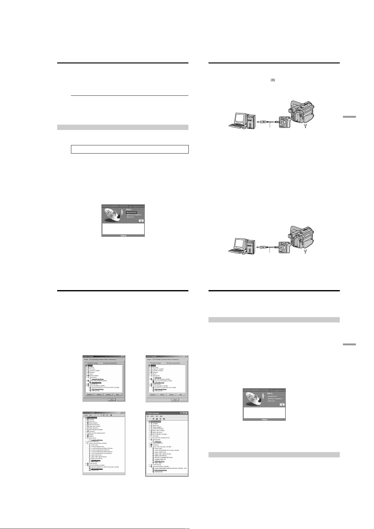
CCD-TRV107/TRV108/TRV308/TRV408/TRV608
Viewing images using your computer – USB Streaming
(Windows users only)
Notes
•Operations are not guaranteed if you connect 2 or more pieces of USB equipment to a
single computer at the same time or when using a hub.
•Depending on the type of USB equipment used simultaneously, some equipment may
not operate.
•Operations are not guaranteed for all the recommended computer environments
mentioned above.
•Microsoft and Windows are registered trademarks of Microsoft Corporation in the
United States and/or other countries.
•Pentium is either registered trademark or trademark of Intel Corporation.
•All other product names mentioned herein may be the trademarks or registered
trademarks of their respective companies.
•Furthermore, “™” or “®” are not mentioned in this manual.
Installing the USB driver
Before connecting your camcorder to your computer, install the USB driver to the
computer. The USB driver is contained together with application software for viewing
images on the CD-ROM supplied with your camcorder.
Be sure to follow the steps before connecting the USB cable to your computer.
Connect the USB cable in step 8.
If the USB driver has been registered incorrectly because your computer was
connected to your camcorder before installing the USB driver, reinstall the USB
driver following the procedure on page 61.
For Windows 98 SE, Windows Me, Windows 2000 Professional and Windows XP
users
Log in with permission of Administrator. (for Windows 2000 Professional and
Windows XP users)
(1) Turn on your computer and allow Windows to load.
(2) Insert the supplied CD-ROM into the CD-ROM drive of your computer. The
application software screen appears.
(3) Move the cursor to “USB Driver” and click. The USB driver installation starts.
Viewing images using your computer – USB Streaming
(Windows users only)
(4) Follow the on-screen messages to install the USB driver.
(5) Connect the AC power adaptor to your camcorder and then to a wall outlet.
(6) Set the POWER switch to CAMERA or PLAYER.
(7) Select USB STREAM to ON in
(8) With the CD-ROM inserted, connect the USB jack on your camcorder to the
USB connector on your computer using the supplied USB cable.
Your computer recognises the camcorder, and the Windows Add Hardware
Wizard starts.
To the USB connector
Computer
(9) Follow the on-screen messages so that the Add Hardware Wizard recognizes
that the USB drivers have been installed. The Add Hardware Wizard starts
three times because three different USB drivers are installed. Be sure to allow
the installation to complete without interrupting it.
If the “Files Needed” screen appears (Windows 2000 Professional and Windows XP
users)
Set the CD-ROM on the CD-ROM driver then select “Browse....” t “My Computer”
t “ImageMixer” t “sonyhcb.sys”, and click the “OK” button.
The installation is completed, procede to Installing “PIXELA ImageMixer Ver.1.0 for
Sony” on page 63.
If you cannot install the USB driver
The USB driver has been registered incorrectly as your computer was connected to your
camcorder before installing the USB driver. Perform the following procedure to
correctly install the USB driver.
Step 1 Uninstall the incorrect USB driver
1 Turn on your computer and allow Windows to load.
2 Connect the USB jack on your camcorder to the USB connector on your
computer using the supplied USB cable.
To the USB connector
in the menu settings (p. 71).
USB cable (supplied)
To the
(USB) jack
PC Connection
60
Viewing images using your computer – USB Streaming
(Windows users only)
3 Connect the AC power adaptor, and set the POWER switch to CAMERA or
PLAYER.
4 Open your computer’s “Device Manager.”
Windows XP:
Select “Start” t “Control Panel” t “System” t “Hardware” tab, and click
the “Device Manager” button.
If “System” is not in the control panel, the “Pick a Category” screen appears. In
this case, click “Switch to Classic View” instead.
Windows 2000 Professional:
Select “My Computer” t “Control Panel” t “System” t “Hardware” tab,
and click the “Device Manager” button.
Windows 98 SE/Windows Me:
Select “My Computer” t “Control Panel” t “System,” and click the “Device
Manager” tab.
5 Select the devices underlined in the illustrations below, and delete them.
Windows 98 SE Windows Me
Windows 2000 Professional
Windows XP
(USB) jack
Computer
Viewing images using your computer – USB Streaming
(Windows users only)
6 Set the POWER switch to OFF (CHG), and then disconnect the USB cable.
7 Reboot your computer.
Step 2 Install the USB driver
Perform the entire procedure listed in “Installing the USB driver” on the page 60.
USB cable (supplied)
To the
Installing “PIXELA ImageMixer Ver.1.0 for Sony”
Install “PIXELA ImageMixer Ver.1.0 for Sony” to your computer. “PIXELA
ImageMixer Ver.1.0 for Sony” is contained on the CD-ROM supplied with your
camcorder. You can view video images easily on your camcorder, using your computer
with “PIXELA ImageMixer Ver.1.0 for Sony”.
For Windows 2000 Professional users
Log in with permission of Power Users or Adminisitrator.
For Windows XP users
Log in with permission of Administrator.
(1) Turn on your computer and allow Windows to load.
While using your computer, close all running applications.
(2) Insert the supplied CD-ROM into the CD-ROM drive of your computer.
The application software screen appears.
If the application software screen does not appear, double-click “My
Computer” and then “ImageMixer” (CD-ROM Drive). The application
software screen appears after a while.
(3) Move the cursor to “PIXELA ImageMixer” and click.
The language selection dialogue box appears.
(4) Select the language for installation.
(5) Follow the on-screen messages.
Follow the directions on the screen to install DirectX. DirectX 8.0 will be installed.
Capturing images with “PIXELA ImageMixer Ver.1.0 for Sony”
For Windows 2000 Professional users
Log in with permission of Power Users or Adminisitrator.
For Windows XP users
Log in with permission of Administrator.
61
PC Connection
62
63
1-15
Page 26
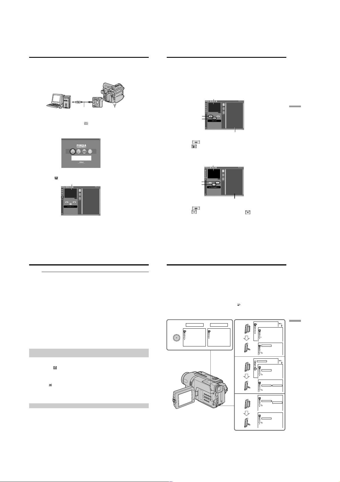
CCD-TRV107/TRV108/TRV308/TRV408/TRV608
Viewing images using your computer – USB Streaming
(Windows users only)
Viewing images
Viewing images recorded on a tape
(1) Turn on your computer and allow Windows to load.
(2) Connect one end of the USB cable to the USB jack on the camcorder and the
other end to the USB connector on your computer using the supplied USB
cable.
To the USB connector
(USB) jack
Computer
(3) Connect the AC power adaptor and insert a cassette to your camcorder.
(4) Set the POWER switch to PLAYER.
(5) Select USB STREAM to ON in
(6) Select “Start” t “Program” t “Pixela” t “ImageMixer” t “PIXELA
ImageMixer Ver.1.0 for Sony” on Windows.
(7) Click the input mode button in the left side of Start-up screen.
(8) Select .
(9) Start playing back a tape on your camcorder. The images recorded on a tape
appears in the preview window.
USB cable (supplied)
in the menu settings (p. 71).
Preview window
To the
Viewing images using your computer – USB Streaming
(Windows users only)
Viewing images live from your camcorder
(1) Follow the procedure (1) - (2) on page 64, and then connect the AC power
adaptor to your camcorder and then to a wall outlet.
(2) Set the POWER switch to CAMERA.
(3) Follow the procedure (5) - (8) on page 64.
The images live from your camcorder appears in the preview window.
Capturing images
Capturing still images
Preview window
1
2
Thumbnail list window
(1) Select .
at the point to capture using the preview window. The captured
(2) Click
image appears on the thumbnail list window.
Capturing moving images
Preview window
1
2
Thumbnail list window
(1) Select .
(2) Click
at the start point to capture and click at the stop point to capture
using the preview window. The captured image appears on the thumbnail list
window.
PC Connection
64
Viewing images using your computer – USB Streaming
(Windows users only)
Notes
•When you view the image using your computer with USB connection, the image may
fluctuate.
•When your camcorder is in the standby mode with a cassette inserted, it turns off
automatically after 5 minutes.
•We recommend setting DEMO MODE to OFF in the menu settings when your
camcorder is in the standby mode, and no cassette is inserted.
•Indicators in the camcorder LCD screen do not appear on images that are captured
into your computer.
If image data cannot be transferred by the USB connection
The USB driver has been registered incorrectly as your computer was connected to your
camcorder before installing the USB driver. Perform the procedure to correctly install
the USB driver (p. 60).
If any trouble occurs
Close all running applications, then restart it.
Carry out the following operations after quitting the application:
– disconnect the USB cable
– turn on/off the power
Seeing the on-line help (operation manual) of ”PIXELA
ImageMixer Ver.1.0 for Sony”
“PIXELA ImageMixer Ver.1.0 for Sony” is provided with on-line help (operation
manual).
(1) Click button located in the upper-right corner of the screen.
The ImageMixer’s Manual screen appears.
(2) You can access the desired topics from the contents.
To close the on-line help
Click located in the upper right corner of the “ImageMixer’s Manual” screen.
If you have any questions about “PIXELA ImageMixer Ver1.0 for Sony”
ImageMixer Ver.1.0 for Sony is a trademark of PIXELA corporation. Refer to the
information web site at: “http://www.imagemixer. com”.
Notes on using your computer
Communications with your computer
Communications between your camcorder and your computer may not recover after
recovering from Suspend, Resume, or Sleep.
— Customizing Your Camcorder —
Changing the menu settings
To change the mode settings in the menu settings, select the menu items with the SEL/
PUSH EXEC dial. The default settings can be partially changed. First, select the icon,
then the menu item and then the mode.
(1) In CAMERA or PLAYER mode, press MENU.
(2) Turn the SEL/PUSH EXEC dial to select the desired icon, then press the dial to
set.
(3) Turn the SEL/PUSH EXEC dial to select the desired item, then press the dial to
set.
(4) Turn the SEL/PUSH EXEC dial to select the desired mode, and press the dial
to set.
(5) If you want to change other items, select
repeat steps from 2 to 4.
RETURN and press the dial, then
For details, see “Selecting the mode setting of each item” (p. 68).
1
MENU
CAMERA
MANUAL S ET
PROGRAM AE
PEFFECT
[
] :
MENU
END
PLAYER
MANUAL S ET
EDI T
TBC
DNR
[
] :
MENU
2
END
3
4
MANUA L SET
PROGRAM AE
PEFFECT
OTHERS
W
BEEP
COMMANDER
DISPLAY
REC LAMP
OTHERS
W
BEEP
COMMANDER
DISPLAY
REC LAMP
OTHERS
W
ORLD T IME
BEEP
OTHERS
W
BEEP
COMMANDER
DISPLAY
REC LAMP
OTHERS
W
BEEP
COMMANDER
DISPLAY
REC LAMP
OTHERS
W
BEEP
COMMANDER
DISPLAY
REC LAMP
OTHERS
W
BEEP
COMMANDER
DISPLAY
REC L AMP
ORLD T IME
ORLD T IME
RETURN
ORLD T I ME
RETURN
ORLD T IME
RETURN
ORLD T I ME
RETURN
ORLD T IME
RETURN
0
HR
0
HR
ON
ON
OFF
ON
OFF
OFF
65
Customizing Your Camcorder
66
1-16
To make the menu display disappear
Press MENU.
67
Page 27
CCD-TRV107/TRV108/TRV308/TRV408/TRV608
Changing the menu settings
Menu items are displayed as the following icons:
MANUAL SET
CAMERA SET
PLAYER SET
LCD/VF SET
TAPE SET
SETUP MENU
OTHERS
Depending on your camcorder model
The menu display may be different from that in this illustration.
Selecting the mode setting of each item z is the default setting.
Menu items differ according to the position of the POWER switch.
The screen shows only the items you can operate at the moment.
Icon/item
PROGRAM AE
P EFFECT
D ZOOM
16:9WIDE
STEADYSHOT*
N.S.LIGHT
Mode
——
——
z OFF
40×
560×
z OFF
40×
460×
z OFF
40×
450×
z OFF
CINEMA
16:9FULL
z ON
OFF
z ON
OFF
Meaning
To suit your specific shooting requirement.
(p. 38)
To add special effects like those in films or on the
TV to images. (p. 37)
If you set to OFF, digital zoom is deactivated and
up to 20× is carried out.
If you set to 40×/560×, digital zoom is activated
and more than 20× to 40×/560× is performed
digitally. (p. 22)
(CCD-TRV408/TRV608 only)
If you set to OFF, digital zoom is deactivated and
up to 20× is carried out.
If you set to 40×/460×, digital zoom is activated
and more than 20× to 40×/460× is performed
digitally. (p. 22)
(CCD-TRV108/TRV308 only)
If you set to OFF, digital zoom is deactivated and
up to 20× is carried out.
If you set to 40×/450×, digital zoom is activated
and more than 20× to 40×/450× is performed
digitally. (p. 22)
(CCD-TRV107 only)
—
To record in the CINEMA mode. (p. 33)
To record in the 16:9FULL mode.
To compensate for camera-shake.
To cancel the SteadyShot function. Natural
pictures are produced when shooting a stationary
object with a tripod.
To use the NightShot Light function. (p. 26)
To cancel the NightShot Light function.
68
POWER
switch
CAMERA
CAMERA
CAMERA
CAMERA
CAMERA
CAMERA
Changing the menu settings
Notes on the SteadyShot function*
•The SteadyShot function will not correct excessive camera-shake.
•Attachment of a conversion lens (optional) may influence the SteadyShot function.
•SteadyShot does not operate in the 16:9FULL mode. If you set STEADYSHOT to ON
in the menu settings, the
If you cancel the SteadyShot function*
The SteadyShot off indicator
compensation for camera-shake.
* CCD-TRV308/TRV408/TRV608 only
Icon/item
EDIT
TBC
TBC stands for “Time Base Corrector.”
DNR
DNR stands for “Digital Noise Reduction.”
Icon/item
LCD BRIGHT
LCD B.L.
LCD COLOR
VF B.L.*
Mode
z OFF
ON
z ON
OFF
z ON
OFF
In more than 5 minutes after removing the power source
The “EDIT” item is returned to their default settings.
The other menu items are held in memory even when the battery is removed.
Mode
—––
z BRT NORMAL
BRIGHT
—––
z BRT NORMAL
BRIGHT
indicator flashes.
appears. Your camcorder prevents excessive
Meaning
—
To minimize picture deterioration when editing.
To correct jitter.
To not correct jitter. Set TBC to OFF when playing
back a tape on which you have dubbed over and
recorded the signal of a TV game or similar
machine.
To reduce picture noise.
To reduce a conspicuous afterimage when the
picture has a lot of movement.
Meaning
To adjust the brightness on the LCD screen with
the SEL/PUSH EXEC dial to adjust the following
bar.
To darken To lighten
To set the brightness on the LCD screen normal.
To brighten the LCD screen.
To adjust the color on the LCD screen, turn the
SEL/PUSH EXEC dial to adjust the following bar.
To reduce
intensity
To set the brightness in the viewfinder normal.
To brighten the viewfinder.
To increase
intensity
POWER
switch
PLAYER
PLAYER
PLAYER
POWER
switch
PLAYER
CAMERA
PLAYER
CAMERA
PLAYER
CAMERA
PLAYER
CAMERA
Customizing Your Camcorder
69
Changing the menu settings
Notes on VF B.L.* and LCD B.L.
•When you select BRIGHT, battery life is reduced by about 10 percent during
recording.
•When you use power sources other than the battery pack, BRIGHT is automatically
selected.
* CCD-TRV107/TRV308/TRV408/TRV608 only
Icon/item
REC MODE
ORC TO SET
ORC stands for “Optimizing the Recording Condition.”
q REMAIN
Mode
z SP
LP
—––
z AUTO
ON
Notes on the LP mode
•When you record a tape in the LP mode on your camcorder, we recommend playing
back the tape on your camcorder. When you play back the tape on other camcorders
or VCRs, noise may occur in images or sound.
•When you record in the LP mode, we recommend using a Sony video cassette so that
you can get the most out of your camcorder.
•When you record in both the SP and LP modes on one tape, or you record some scenes
in the LP mode, the playback image may be distorted.
•Noise may occur also when you play back on your camcorder tapes recorded in the
LP mode on other camcorders or VCRs.
•When you record a tape in the LP mode on your camcorder, recording is carried out in
the standard 8 mm system.
Meaning
To record in the SP (Standard Play) mode.
To increase the recording time to twice the SP
mode.
To automatically adjust the recording condition
to get the best possible recording. Press
START/STOP to start adjustment. Your
camcorder takes about 10 seconds to check the
tape condition and then returns to the standby
mode.
To display the remaining tape bar:
– for about 8 seconds after your camcorder is
turned on and calculates the remaining
amount of tape.
– for about 8 seconds after a cassette is inserted
and your camcorder calculates the remaining
amount of tape.
– for about 8 seconds after N is pressed in
PLAYER mode.
– for about 8 seconds after DISPLAY is pressed
to display the screen indicators.
– for the period of tape rewinding, forwarding
or picture search in PLAYER mode.
To always display the remaining tape bar.
POWER
switch
CAMERA
CAMERA
PLAYER
CAMERA
Changing the menu settings
Notes on ORC setting
•Each time you eject the cassette, the ORC setting will be canceled. If necessary, set the
setting.
•You cannot use this setting on a tape with the red mark on the cassette exposed.
(i. e. the tape is write-protected)
•When you set ORC TO SET, a non-recorded section of about 0.1 second appears on the
tape. However, note that this non-recorded section disappears from the tape when
you continue recording from this section.
•To check if you have already set the ORC setting, select ORC TO SET in the menu
settings. “ORC ON” is displayed if ORC TO SET is already set.
Icon/item
CLOCK SET
AUTO DATE
USB STREAM
LTR SIZE
LANGUAGE
DEMO MODE
Mode
——
z ON
OFF
z OFF
ON
z NORMAL
2×
z ENGLISH
FRANÇAIS
ESPAÑOL
PORTUGUÊS
z ON
OFF
Notes on DEMO MODE
•You cannot select DEMO MODE when a cassette is inserted in your camcorder.
•DEMO MODE is set to STBY (Standby) at the factory and the demonstration starts
about 10 minutes after you have set the POWER switch to CAMERA without a
cassette inserted.
To cancel the demonstration, insert a cassette, set the POWER switch to other than
CAMERA, or set DEMO MODE to OFF.
•When NIGHTSHOT is set to ON, “NIGHTSHOT” indicator appears on the screen
and you cannot select DEMO MODE in the menu settings.
Meaning
To set the date or time. (p. 16)
To record the date for 10 seconds after
recording has started.
To cancel the auto date function.
To deactivate the USB Streaming function.
To activate the USB Streaming function.
To display selected menu items in normal size.
To display selected menu items at twice the
normal size.
To display the following information indicators
in English: min, STBY, REC, VOL,
END SEARCH and START.
To display the information indicators in
French.
To display the information indicators in
Spanish.
To display the information indicators in
Portuguese.
To display the information indicators in
Chinese.
To display the information indicators in
Korean.
To make the demonstration appear.
To cancel the demonstration mode.
POWER
switch
CAMERA
CAMERA
PLAYER
CAMERA
PLAYER
CAMERA
PLAYER
CAMERA
CAMERA
Customizing Your Camcorder
70
71
1-17
Page 28

CCD-TRV107/TRV108/TRV308/TRV408/TRV608
Changing the menu settings
Icon/item
WORLD TIME
BEEP
COMMANDER*
DISPLAY
REC LAMP
Mode
——
z MELODY
NORMAL
OFF
z ON
OFF
z LCD
V-OUT/LCD
z ON
OFF
In more than 5 minutes after removing the power source
The “COMMANDER”* item is returned to the default setting.
The other menu items are held in memory even when the battery is removed.
Recording a close-up picture
When REC LAMP is set to ON, the red recording lamp on the front of the camcorder
may reflect on the subject if it is close. In this case, we recommend you set REC LAMP
to OFF.
* CCD-TRV107/TRV408 only
Meaning
To set the clock to the local time.
Turn the SEL/PUSH EXEC dial to set the time
difference. The clock changes by the time
difference you set here. If you set the time
difference to 0, the clock returns to the
originally set time.
To output the melody when you start/stop
recording or when an unusual condition occurs
on your camcorder
To output the beep instead of the melody
To cancel the melody and beep sound
To activate the Remote Commander supplied
with your camcorder
To deactivate the Remote Commander to avoid
unintentional operations caused by other
VCR’s remote controls.
To show the display on the LCD screen and in
the viewfinder
To show the display on the TV screen, LCD
screen, and in the viewfinder
To light up the recording lamp at the front of
your camcorder when recording
To turn the recording lamp off so that the
subject is not aware of the recording
POWER
switch
CAMERA
PLAYER
CAMERA
PLAYER
CAMERA
PLAYER
CAMERA
CAMERA
— Troubleshooting —
Types of trouble and their solutions
If you run into any problem using your camcorder, use the following table to
troubleshoot the problem. If the problem persists, disconnect the power source and
contact your Sony dealer or local authorized Sony service facility. If “C:ss:ss”
appears on the screen, the self-diagnosis display function has worked. See page 77.
In the recording mode
Symptom Cause and/or Corrective Actions
START/STOP does not operate.
The power goes off.
The image on the viewfinder screen
is not clear.
The SteadyShot function does not
work.*
The autofocusing function does not
work.
The x indicator flashes in the
viewfinder.
The picture does not appear in the
viewfinder.
A vertical band appears when you
shoot a subject such as lights or a
candle flame against a dark
background.
A vertical band appears when you
shoot a very bright subject.
• The POWER switch is set to OFF (CHG) or PLAYER.
c Set it to CAMERA. (p. 19)
• The tape has run out.
c Rewind the tape or insert a new one. (p. 18, 29)
• The write-protect tab is set to expose the red mark.
c Use a new tape or slide the tab. (p. 18)
• The tape is stuck to the drum (moisture condensation).
c Remove the cassette and leave your camcorder for at
least 1 hour to acclimate. (p. 84)
• While being operated in CAMERA mode, your camcorder
has been in the standby mode for more than 5 minutes.
c Set the POWER switch to OFF (CHG) and then to
CAMERA again. (p. 19)
• The battery pack is dead or nearly dead.
c Install a fully charged battery pack. (p. 11, 12)
• The viewfinder lens is not adjusted.
c Adjust the viewfinder lens. (p. 23)
• STEADYSHOT is set to OFF in the menu settings.
c Set it to ON. (p. 68)
• The wide mode is set to 16:9FULL.
c Set it to OFF. (p. 68)
• The setting is the manual focus mode.
c Press FOCUS to return to the autofocus mode. (p. 41)
• Shooting conditions are not suitable for autofocus.
c Adjust to focus manually. (p. 41)
• The video heads may be dirty.
c Clean the heads using the Sony V8-25CLD cleaning
cassette (optional). (p. 85)
• The LCD panel is open.
c Close the LCD panel. (p. 20)
• The contrast between the subject and background is too
high. This is not a malfunction.
• This is not a malfunction.
(continued on the following page)
Troubleshooting
72
Types of trouble and their solutions
Symptom Cause and/or Corrective Actions
An unknown picture is displayed on
the screen.
The picture is recorded in incorrect or
unnatural colors.
The picture appears too bright, and
the subject does not appear on the
screen.
A horizontal black band appears
when shooting a TV screen or
computer screen.*
* CCD-TRV308/TRV408/TRV608 only
In the playback mode
Symptom Cause and/or Corrective Actions
The tape does not move when a
video control button is pressed.
The playback button does not work.
The playback picture is not clear or
does not appear.
No sound or only a low sound is
heard when playing back a tape.
In the recording and playback modes
Symptom Cause and/or Corrective Actions
The power does not turn on.
• If 10 minutes elapse after you set the POWER switch to
CAMERA or DEMO MODE is set to ON in the menu
settings without a cassette inserted, your camcorder
automatically starts the demonstration.
c Insert a cassette and the demonstration stops.
You can also cancel DEMO MODE. (p. 71)
• NIGHTSHOT is set to ON.
c Set it to OFF. (p. 26)
• NIGHTSHOT is set to ON in a bright place.
c Set it to OFF or use the NightShot function in a dark
place. (p. 26)
• The backlight function is working.
c Cancel it. (p. 25)
• Set STEADYSHOT to OFF in the menu setting. (P. 68)
• The POWER switch is set to CAMERA or OFF (CHG).
c Set it to PLAYER. (p. 29)
• The tape has run out.
c Rewind the tape. (p. 29)
• The television’s video channel is not adjusted correctly.
c Adjust it. (p. 32)
• EDIT is set to ON in the menu settings.
c Set it to OFF. (p. 69)
• The video head may be dirty.
c Clean the heads using the Sony V8-25CLD cleaning
cassette (optional). (p. 85)
• The volume is turned to minimum.
c Open the LCD panel and press VOLUME +. (p. 29)
• The battery pack is not installed, or is dead or nearly dead.
c Install a charged battery pack. (p. 11, 12)
• The AC power adaptor is not connected to a wall outlet.
c Connect the AC power adaptor to a wall outlet. (p. 15)
Types of trouble and their solutions
Symptom Cause and/or Corrective Actions
The end search function does not
work.
The battery pack discharges quickly.
The remaining battery time indicator
does not indicate the correct time.
The power goes off although the
remaining battery time indicator
indicates that the battery pack has
enough power to operate.
The cassette cannot be removed from
the holder.
The % and Z indicators flash and no
functions except for cassette ejection
work.
The remaining tape indicator is not
displayed.
• The tape was ejected after recording.
• You have not recorded on the cassette yet.
• The operating temperature is too low.
• The battery pack is not fully charged.
c Charge the battery pack fully again. (p. 11, 12)
• The battery pack is completely dead, and cannot be
recharged.
c Replace with a new battery pack. (p. 11)
• You have used the battery pack in an extremely hot or
cold environment for a long time.
• The battery pack is completely dead, and cannot be
recharged.
c Replace with a new battery pack. (p. 11)
• The battery pack is not fully charged.
• A deviation has occured in the remaining battery time.
c Charge the battery pack fully again. (p. 11, 12)
• A deviation has occured in the remaining battery time.
c Charge the battery pack fully again so that the
indication on the battery remaining indicator is correct.
(p. 11, 12)
• The power source is disconnected.
c Connect it firmly. (p. 11, 15)
• The battery pack is dead.
c Use a charged battery pack. (p. 11, 12)
• Moisture condensation has occurred.
c Remove the cassette and leave your camcorder for at
least 1 hour to acclimate. (p. 84)
• The q REMAIN is set to AUTO in the menu settings.
c Set it to ON to always display the remaining tape
indicator. (p. 70)
Others
Symptom Cause and/or Corrective Actions
Easy Dubbing does not function.
• Your VCR and/or video camera recorder is not set
correctly.
c Make sure the input selector of the VCR is set to LINE.
Also, make sure the power switch of the video camera is
set to VTR/VCR. (p. 51)
• The IR SETUP code or PAUSE MODE is not set correctly.
c Select the correct IR SETUP code and PAUSE MODE,
according to your VCR. Then confirm VCR operation
with the IR TEST function. (p. 52 to 55)
(continued on the following page)
73
Troubleshooting
74
75
1-18
Page 29
CCD-TRV107/TRV108/TRV308/TRV408/TRV608
Types of trouble and their solutions
Symptom Cause and/or Corrective Actions
You cannot install the USB driver.*
USB Streaming function does not
1)
work*
The Remote Commander supplied
with your camcorder does not
2)
work.*
The date or time indicator does not
appear, and the bars
“--:--:--” appear.
The melody or beep sounds for 5
seconds.
No function works though the power
is on.
While charging the battery pack, no
indicator appears or the indicator
flashes in the display window.
You cannot charge the battery pack
installed to your camcorder.
*1)CCD-TRV608 only
2)
CCD-TRV107/TRV408 only
*
1)
• Your camcorder was connected to your computer with the
USB cable before installing the USB driver, so the driver
was not recognized by the computer.
c Uninstall the unrecognized driver, and then reinstall the
driver. (p. 60)
• The USB driver is not installed correctly.
c Uninstall the unrecognized driver, and then reinstall the
driver. (p. 61 to 63)
• Your computer's operating system is Windows 98 or
earlier.
• The USB cable was not connected before starting up the
application software.
c Connect the USB cable before starting up the application
software. (p. 63)
• COMMANDER is set to OFF in the menu settings.
c Set it to ON. (p. 72)
• Something is blocking the infrared rays.
c Remove the obstacle.
• The batteries are inserted in the battery holder with the
+ – polarities incorrectly matching the + – marks.
c Insert the batteries with the correct polarity. (p. 96)
• The batteries are dead.
c Insert new ones. (p. 96)
• Set the date and time. (p. 16)
• Moisture condensation has occurred.
c Remove the cassette and leave your camcorder for at
least 1 hour to acclimate. (p. 84)
• Some troubles have occurred in your camcorder.
c Remove the cassette and insert it again, then operate
your camcorder.
• Disconnect the power cord of the AC power adaptor or
remove the battery pack, then reconnect it after about
1 minute. Turn the power on. (p. 19) If the functions still
do not work, press RESET using a sharp-pointed object. (If
you press RESET, all the settings including the date and
time return to the default.) (p. 95)
• The AC power adaptor is disconnected.
c Connect it firmly. (p. 15)
• The battery pack is not installed properly.
c Install it properly.
• Something is wrong with the battery pack.
c Contact your Sony dealer or local authorized Sony
service facility.
• The POWER switch is not set to OFF (CHG).
c Set it to OFF (CHG).
76
Self-diagnosis display
Your camcorder has a self-diagnosis display
function.
This function displays the current condition of
your camcorder as a 5-digit code (a combination of
a letter and figures) on the LCD screen, in the
viewfinder or in the display window.
If a 5-digit code is displayed, check the following
code chart. The last two digits (indicated by ss)
will differ depending on the state of your
camcorder.
Five-digit display Cause and/or Corrective Actions
C:04:ss
C:21:ss
C:22:ss
C:31:ss
C:32:ss
E:20:ss
E:61:ss
E:62:ss
If you are unable to rectify the problem even if you try corrective actions a few times, contact your
Sony dealer or local authorized Sony service facility.
• You are using a battery pack that is not an
“InfoLITHIUM” battery pack.
c Use an “InfoLITHIUM” battery pack. (p. 81)
• Moisture condensation has occurred.
c Remove the cassette and leave your camcorder for at
least 1 hour to acclimate. (p. 84)
• The video heads are dirty.
c Clean the heads using the Sony V8-25CLD cleaning
cassette (optional). (p. 85)
• A malfunction other than the above that you can service
has occurred.
c Remove the cassette and insert it again, then operate
your camcorder.
c Disconnect the power cord of the AC power adaptor or
remove the battery pack. After reconnecting the power
source, operate your camcorder.
• A malfunction that you cannot service has occurred.
c Contact your Sony dealer or local authorized Sony
service facility and inform them of the 5-digit code.
(example: E:61:10)
LCD screen, viewfinder
or display window
C:21:00
Self-diagnosis display
•C:ss:ss
You can service your camcorder
yourself.
•E:ss:ss
Contact your Sony dealer or local
authorized Sony service facility.
Troubleshooting
77
Warning indicators and messages
If indicators and messages appear on the screen or in the display window, check the
following:
See the page in parentheses “()” for more information.
Warning indicators
The video heads are dirty
Slow flashing:
– You need to clean the heads using the Sony V8-25CLD
cleaning cassette (optional). (p. 85)
The battery pack is dead or
nearly dead
Slow flashing:
– The battery pack is nearly dead.
(P. 12)
Depending on conditions, the
environment or the battery pack,
the warning indicator may flash,
even if there are 5 to 10 minutes
battery remaining.
Fast flashing:
– The battery pack is dead.
– The battery pack is completely
dead, and cannot be charged.
Tape warning indicator
Slow flashing:
– The tape is near the end.
– No tape is inserted.*
– The write-protect tab on the
cassette is out (red).*1) (p. 18)
Fast flashing:
– The tape has run out.*
1)
1)
*1)You hear the melody or beep sound.
*2)This indicator appears in the viewfinder only.
C:21:00
Self-diagnosis display (p. 77)
Moisture condensation has
occurred*
Fast flashing:
– Eject the cassette, turn off your
camcorder, and leave it for
about 1 hour with the cassette
compartment open. (p. 84)
You need to eject the cassette*
Slow flashing:
– The write-protect tab on the
cassette is out (red). (p. 18)
Fast flashing:
– Moisture condensation has
occurred. (p. 84)
– The tape has run out.
– The self-diagnosis display
function is activated. (p. 77)
Tape/Battery pack warning
indicator*
Slow flashing:
– The battery pack is nearly dead.
– The tape is near the end.
Fast flashing:
– The battery pack is dead.
– The tape has run out.*
Warning indicators and messages
Warning messages
•CLOCK SET Set the date and time. (p. 16)
•FOR “InfoLITHIUM” Use an “InfoLITHIUM” battery pack. (p. 81)
BATTERY ONLY
•Q NO TAPE*
•Q TAPE END*
• CLEANING CASSETTE*2)The video heads are dirty. (p. 85)
•START/STOP KEY Press START/STOP to activate the ORC setting. This
•ORC The ORC setting is working. This message is
*1)You hear the melody or beep sound.
*2)The x indicator and “ CLEANING CASSETTE” message appear one after another
1)
1)
2)
1)
on the screen.
1)
1)
Insert a cassette tape.
The tape has reached the end.
message is displayed in white. (p. 70)
displayed in white. (p. 70)
Troubleshooting
78
79
1-19
Page 30
CCD-TRV107/TRV108/TRV308/TRV408/TRV608
— Additional Information —
About video cassettes
Selecting the cassette type
You can use both Hi8 and standard 8 mm video cassettes on your camcorder.
When you play back
80
When you use a Hi8
Hi8 system. When you use a standard 8 mm video cassette, recording and
playback are carried out in the standard 8 mm system.
However, if you record on a Hi8
carried out in the standard 8 mm system.
If you play back a tape recorded on a different video recorder on your camcorder, the
playback mode is automatically selected according to the format in which the tape has
been recorded.
This Hi8
developed to produce higher quality pictures.
You cannot play back a tape recorded in the Hi8
recorders/players other than a Hi8 video recorder/player.
is a trademark.
is a trademark.
The playback mode (SP/LP) and system, Hi8 , or standard 8 mm are
automatically selected according to the format in which the tape has been recorded. The
quality of the recorded picture in the LP mode, however, will not be as good as the SP
mode.
Foreign 8 mm video
Because TV color systems differ from country to country, you may not be able to play
back foreign pre-recorded tapes. Refer to “Using your camcorder abroad” (p. 83) to
check the TV color systems used in foreign countries.
video cassette, recording and playback are carried out in the
video cassette in the LP mode, recording is
system is an extension of the standard 8 mm system, and was
system correctly on video
About the “InfoLITHIUM” battery pack
What is the “InfoLITHIUM” battery pack?
The “InfoLITHIUM” battery pack is a lithium-ion battery pack that has functions for
communicating information related to operating conditions between your camcorder
and the AC power adaptor.
The “InfoLITHIUM” battery pack calculates the power consumption according to the
operating conditions of your camcorder, and displays the remaining battery time in
minutes.
Charging the battery pack
•Be sure to charge the battery pack before you start using your camcorder.
•We recommend charging the battery pack in an ambient temperature of between 10°C
to 30°C (50°F to 86°F) until FULL appears indicating that the battery pack is fully
charged, in the display window. If you charge the battery pack outside of this
temperature range, you may not be able to efficiently charge the battery pack.
•After charging is completed, either disconnect the cable from the DC IN jack on your
camcorder or remove the battery pack.
Effective use of the battery pack
•Battery performance decreases in low-temperature surroundings. So, the time that the
battery pack can be used is shorter in cold places. We recommend the following to use
the battery pack longer:
– Put the battery pack in a pocket to warm it up, and insert it in your camcorder
immediately before you start taking shots.
– Use a large capacity battery pack (NP-FM50/FM70/QM71/FM90/FM91/QM91,
optional).
•Frequently using the LCD panel or frequently operating playback, fast forward or
rewind wears out the battery pack faster. We recommend using a large capacity
battery pack (NP-FM50/FM70/QM71/FM90/FM91/QM91, optional).
•Be certain to turn the POWER switch to OFF (CHG) when not taking shots or playing
back on your camcorder. Battery pack power is also consumed when your camcorder
is in the standby mode or playback is paused.
•Have spare battery packs handy for two or three times the expected recording time,
and make a trial recording before the actual recording.
•Do not expose the battery pack to water. The battery pack is not water-resistant.
Remaining battery time indicator
•If the power goes off although the remaining battery time indicator indicates that the
battery pack has enough power to operate, charge the battery pack fully again so that
the indication on the remaining battery time indicator is correct. Note, however, that
the correct battery indication sometimes will not be restored if it is used in high
temperatures for a long time or left in a fully charged state, or the battery pack is
frequently used. Regard the remaining battery time indication as approximate.
•The E mark, indicating there is little remaining battery time, sometimes flashes
depending on the operating conditions or ambient temperature and environment even
if the remaining battery time is 5 to 10 minutes.
How to store the battery pack
•If the battery pack is not used for a long time, do the following once a year to maintain
proper function.
1. Fully charge the battery pack.
2. Discharge on your camcorder.
3. Remove the battery pack from your camcorder and store it in a dry, cool place.
•To discharge the battery pack on your camcorder, leave your camcorder in CAMERA
(standby) mode without a cassette inserted until the power goes off.
Additional Information
81
About “InfoLITHIUM” battery pack
Battery life
•The battery life is limited. Battery capacity drops little by little as you use it more and
more, and as time passes. When the available battery time is shortened considerably, a
probable cause is that the battery pack has reached the end of its life. Please buy a new
battery pack.
•The battery life varies according to storage and operating conditions, and
environment for each battery pack.
Using your camcorder abroad
Using your camcorder abroad
You can use your camcorder in any country or area with the AC power adaptor
supplied with your camcorder within 100 V to 240 V AC, 50/60 Hz.
When charging the battery pack, use a commercially available AC plug adaptor [a], if
necessary, depending on the design of the wall outlet [b].
AC-L10A/L10B/L10C
[a] [b]
Your camcorder is an NTSC system based camcorder. If you want to view the playback
picture on a TV, it must be an NTSC system based TV with Video/Audio input jack.
The following shows TV color systems used overseas.
NTSC system
Bahama Islands, Bolivia, Canada, Central America, Chile, Colombia, Ecuador, Guyana,
Jamaica, Japan, Korea, Mexico, Peru, Surinam, Taiwan, the Philippines, the U.S.A.,
Venezuela, etc.
PAL system
Australia, Austria, Belgium, China, Czech Republic, Denmark, Finland, Germany,
Holland, Hong Kong, Hungary, Italy, Kuwait, Malaysia, New Zealand, Norway,
Poland, Portugal, Singapore, Slovak Republic, Spain, Sweden, Switzerland, Thailand,
United Kingdom, etc.
PAL-M system
Brazil
PAL-N system
Argentina, Paraguay, Uruguay
SECAM system
Bulgaria, France, Guiana, Iran, Iraq, Monaco, Russia, Ukraine, etc.
Simple setting of clock by time difference
You can easily set the clock to the local time by setting a time difference. Select WORLD
TIME in the menu settings. See page 72 for more information.
Additional Information
82
83
1-20
Page 31

Maintenance information and
precautions
Moisture condensation
If your camcorder is brought directly from a cold place to a warm place, moisture may
condense inside your camcorder, on the surface of the tape, or on the lens. In this
condition, the tape may stick to the head drum and be damaged or your camcorder may
not operate correctly. If there is moisture inside your camcorder, the beep sounds and
the % indicator flashes. When the Z indicator flashes at the same time, the cassette is
inserted in your camcorder. If moisture condenses on the lens, the indicator will not
appear.
If moisture condensation occurs
None of the functions except cassette ejection will work. Eject the cassette, turn off your
camcorder, and leave it for about 1 hour with the cassette compartment open. Your
camcorder can be used again if the % indicator does not appear when the power is
turned on again.
Note on moisture condensation
Moisture may condense when you bring your camcorder from a cold place into a warm
place (or vice versa) or when you use your camcorder in a hot place as follows:
– You bring your camcorder from a ski slope into a place warmed up by a heating
device.
– You bring your camcorder from an air-conditioned car or room into a hot place
outside.
– You use your camcorder after a squall or a shower.
– You use your camcorder in a high temperature and humid place.
How to prevent moisture condensation
When you bring your camcorder from a cold place into a warm place, put your
camcorder in a plastic bag and tightly seal it. Remove the bag when the air temperature
inside the plastic bag has reached the surrounding temperature (after about 1 hour).
CCD-TRV107/TRV108/TRV308/TRV408/TRV608
Maintenance information and precautions
Maintenance information
Cleaning the LCD screen
If fingerprints or dust make the LCD screen dirty, we recommend using a LCD
Cleaning Kit (optional) to clean the LCD screen.
Cleaning the video head
To ensure normal recording and clear pictures, clean the video heads.
The video head may be dirty when:
– the x indicator and “
on the screen or the x indicator flashes on the screen.
– playback pictures contain noise.
– playback pictures are hardly visible.
– playback pictures do not appear.
[a] Slightly dirty
[b] Very dirty
If the above problem occurs, clean the video heads with the Sony V8-25CLD cleaning
cassette (optional). Check the picture and if the above problem persists, repeat cleaning.
Note on video heads
When the playback pictures still contain noise even if you have cleaned the video heads
with a cleaning cassette, the video heads may have worn down due to long use. If this is
the case, they must be replaced with new heads. Contact your Sony dealer or local
authorized Sony service facility.
CLEANING CASSETTE” message appear one after another
Additional Information
84
Maintenance information and precautions
Charging the built-in rechargeable battery in your camcorder
A built-in rechargeable battery is supplied with your camcorder so as to retain the date
and time, etc., regardless of the setting of the POWER switch. The rechargeable battery
is always charged as long as you are using your camcorder. The battery, however, will
get discharged in about 6 months if you do not use your camcorder at all. Even if the
rechargeable battery is not charged, it will not affect the camcorder operation. To retain
the date and time, etc., charge the battery pack if the battery pack is discharged.
Charging the built-in rechargeable battery:
– Connect your camcorder to the wall outlet using the AC power adaptor supplied with
your camcorder, and leave your camcorder with the POWER switch turned off for
more than 24 hours.
– Or install the fully charged battery pack in your camcorder, and leave your camcorder
with the POWER switch turned off for more than 24 hours.
Precautions
Camcorder operation
•Operate your camcorder on 7.2 V (battery pack) or 8.4 V (AC power adaptor).
•For DC or AC operation, use the accessories recommended in these operating
instructions.
•If any solid object or liquid get inside the casing, unplug your camcorder and have it
checked by a Sony dealer before operating it any further.
•Avoid rough handling or mechanical shock. Be particularly careful with the lens.
•
Keep the POWER switch set to OFF (CHG) when you are not using your camcorder.
•Do not wrap your camcorder with a towel, for example, and operate it. Doing so
might cause heat to build up inside.
•Keep your camcorder away from strong magnetic fields or mechanical vibration.
Noise may occur on images.
•Do not touch the LCD screen with your fingers or a sharp-pointed object.
•If your camcorder is used in a cold place, a residual image may appear on the LCD
screen. This is not a malfunction.
•While using your camcorder, the back of the LCD screen may heat up. This is not a
malfunction.
Maintenance information and precautions
Built-in light (CCD-TRV107/TRV308/TRV408/TRV608 only)
•Do not knock or jolt the built-in light while it is turned on as it may damage the bulb
or shorten the life of the bulb.
•Do not leave the built-in light on while it is resting on or against something; it may
cause a fire or damage the built-in light.
On handling tapes
Do not insert anything into the small holes on the rear of the cassette. These holes are
used to sense the type and thickness of the tape and if the recording tab is in or out.
Camcorder care
•Remove the tape, and periodically turn on the power, operate the CAMERA and
PLAYER sections and play back a tape for about 5 minutes when your camcorder is
not to be used for a long time.
•Clean the lens with a soft brush to remove dust. If there are fingerprints on the lens,
remove them with a soft cloth.
•Clean the camcorder body with a dry soft cloth, or a soft cloth lightly moistened with
a mild detergent solution. Do not use any type of solvent which may damage the
finish.
•Do not let sand get into your camcorder. When you use your camcorder on a sandy
beach or in a dusty place, protect it from the sand or dust. Sand or dust may cause
your camcorder to malfunction, and sometimes this malfunction cannot be repaired.
AC power adaptor
•Unplug the unit from the wall outlet when you are not using the unit for a long time.
To disconnect the power cord, pull it out by the plug. Never pull the power cord itself.
•Do not operate the unit with a damaged cord or if the unit has been dropped or
damaged.
•Do not bend the power cord forcibly, or place a heavy object on it. This will damage
the cord and may cause fire or electrical shock.
•Prevent metallic objects from coming into contact with the metal parts of the
connecting section. If this happens, a short may occur and the unit may be damaged.
•Always keep metal contacts clean.
•Do not disassemble the unit.
•Do not apply mechanical shock or drop the unit.
•While the unit is in use, particularly during charging, keep it away from AM receivers
and video equipment. AM receivers and video equipment disturb AM reception and
video operation.
•The unit becomes warm during use. This is not a malfunction.
•Do not place the unit in locations that are:
– Extremely hot or cold
– Dusty or dirty
– Very humid
– Vibrating
85
Additional Information
86
87
1-21
Page 32

CCD-TRV107/TRV108/TRV308/TRV408/TRV608
Maintenance information and precautions
About care and storage of the lens
•Wipe the surface of the lens with a soft cloth in the following instances:
– When there are fingerprints on the lens surface
– In hot or humid locations
– When the lens is used in environments susceptible to salt such as the seaside
•Store the lens in a well-ventilated location subject to little dirt or dust.
To prevent mold from growing on the lens, periodically perform the above.
We recommend turning on and operating your camcorder at least once per month to
keep your camcorder in an optimum state for a long time.
Battery pack
•Use only the specified charger or video equipment for the charging function.
•To prevent an accidental short circuit, do not allow metal objects to come into contact
with the battery terminals.
•Keep the battery pack away from fire.
•Never expose the battery pack to temperatures above 60°C (140°F), such as in a car
parked in the sun or under direct sunlight.
•Keep the battery pack dry.
•Do not expose the battery pack to any mechanical shock.
•Do not disassemble nor modify the battery pack.
•Attach the battery pack to the video equipment securely.
•Charging while some capacity remains does not affect the original battery capacity.
Note on dry batteries (CCD-TRV107/TRV408 only)
To avoid possible damage from battery leakage or corrosion, observe the following:
– Be sure to insert the batteries with the + – polarities matched to the + – marks
– Dry batteries are not rechargeable
– Do not use a combination of new and old batteries
– Do not use different types of batteries
– Current drains from batteries when you are not using them for a long time
– Do not use leaking batteries
If batteries are leaking
•Wipe off the liquid in the battery compartment carefully before replacing the batteries.
•If you touch the liquid, wash it off with water.
•If the liquid get into your eyes, wash your eyes with a lot of water and then consult a
doctor.
If any problem occurs, unplug your camcorder and contact your nearest Sony dealer.
— Quick Reference —
Identifying the parts and controls
Camcorder
1
2
3
4
5
6
1 Eyecup
2 Viewfinder lens adjustment lever
(p. 23)
3 V BATT release lever (p. 11)
USB connector (p. 61)
4
(CCD-TRV608 only)
5 OPEN button (p. 19)
Attaching the shoulder strap
Attach the shoulder strap supplied with your camcorder to the hooks for the shoulder
strap.
6 SEL/PUSH EXEC dial (p. 16, 67)
7 Power zoom lever (p. 22)
8 POWER switch (p. 19)
9 START/STOP button (p. 19)
0 DC IN jack (p. 12, 15)
qa Hooks for shoulder strap (p. 91)
7
8
9
q;
qa
Quick Reference
88
Identifying the parts and controls
qs
qd
qf
qg
qh
qs Video control buttons (p. 29, 31)
x STOP (stop)
m REW (rewind)
N PLAY (playback)*
M FF (fastforward)
X PAUSE (pause)
qd LIGHT button (p. 46)
(CCD-TRV107/TRV308/TRV408/
TRV608 only)
qf Recording lamp (p. 19)
qg Infrared rays emitter (p. 26)
* This button has a tactile dot.
qh Remote sensor (p. 96)
(CCD-TRV107/TRV408 only)
qj NIGHTSHOT switch (p. 26)
qk Display window (p. 97)
ql Microphone (p. 19)
w; Tripod receptacle (base)
Make sure that the length of the tripod
screw is less than 5.5 mm (7/32 in.).
Otherwise, you cannot attach the tripod
securely and the screw may damage
your camcorder.
qj
qk
ql
w;
Identifying the parts and controls
wa
ws
wd
wf
wg
wh
wa VOLUME +*/– buttons (p. 29)
ws Speaker
wd LCD screen (p. 19)
wf EXPOSURE button (p. 40)
wg TITLE button (p. 42, 44)
wh EASY DUBBING button (p. 51)
wj DISPLAY button (p. 30)
* This button has a tactile dot.
wk END SEARCH button (p. 28)
wl Viewfinder (p. 23)
e; FADER button* (p. 35)
ea BACK LIGHT button (p. 25)
es FOCUS button (p. 41)
ed MENU button* (p. 67)
91
wj
wk
wl
e;
ea
es
ed
Quick Reference
92
93
1-22
Page 33

CCD-TRV107/TRV108/TRV308/TRV408/TRV608
Identifying the parts and controls
ef
eg
eh
ef DATE button (p. 27)
eg TIME button* (p. 27)
eh COUNTER RESET button (p. 20)
* This button has a tactile dot.
Identifying the parts and controls
ej
ek
el
ej Z EJECT button (p. 18)
ek Cassette compartment (p. 18)
el Grip strap
r; RESET button (p. 76)
ra S VIDEO OUT jack (p. 32, 49, 51)
Fastening the grip strap
Fasten the grip strap firmly.
Attaching the lens cap
Attach the lens cap to the grip strap as illustrated.
r;
ra
rs
rd
rf
rs Built-in light (p. 46)
(CCD-TRV107/TRV308/TRV408/
TRV608 only)
rd A/V OUT jack (p. 32, 49)
rf RFU DC OUT (RFU adaptor DC output)
jack (p. 32)
Quick Reference
94
Identifying the parts and controls
Remote Commander
— CCD-TRV107/TRV408 only
The buttons that share the same name on the Remote Commander and your camcorder
function identically to the buttons on your camcorder.
1
2
3
1 Transmitter
Point toward the remote sensor to
control the camcorder after turning on
the camcorder.
2 Tape transport buttons (p. 31)
To prepare the Remote Commander
Insert 2 size AA (R6) batteries by matching the + and – polarities on the batteries to
the + – marks inside the battery compartment.
Notes on the Remote Commander
•Point the remote sensor away from strong light sources such as direct sunlight or
overhead lighting. Otherwise, the Remote Commander may not function properly.
•Your camcorder works in the commander mode VTR 2. The commander modes
1, 2 and 3 are used to distinguish your camcorder from other Sony VCRs to avoid
remote control unintentional operations. If you use another Sony VCR in the
commander mode VTR 2, we recommend changing the commander mode or covering
the sensor of the VCR with black paper.
96
4
5
3 DISPLAY button (p. 30)
4 START/STOP button (p. 19)
5 Power zoom button (p. 22)
Identifying the parts and controls
Operation indicators
LCD screen and Viewfinder Display window
0:00:00
END
SEARCH
4LUJ
2002
65:50:21
qf
qg
FULL
qh
qj
qk
ql
w;
wa
ws
1
2
3
4
5
6
min
40
M. FADER
CINEMA
SEP I A
REC
TW
7
8
9
0
qa
qs
qd
1 Recording mode indicator (p. 70)/
Mirror mode indicator (p. 20)
2 Hi8 format indication (p. 24)
3 Remaining battery time indicator
(p. 24)
4 Zoom indicator (p. 22)/
Exposure indicator (p. 40)
5 Fader indicator (p. 35)
6 Wide mode indicator (p. 33)
7 Picture effect indicator (p. 37)
8 Volume indicator (p. 29)
9 PROGRAM AE indicator (p. 38)
0 Backlight indicator (p. 25)
qa SteadyShot off indicator*
qs Manual focusing indicator (p. 41)
qd Built-in light indicator*
qf STBY/REC indicator (p. 19)/
Video control mode indicator (p. 31)
2)
(p. 46)
1)
(p. 69)
qg Tape counter indicator (p. 24)/
Self-diagnosis display indicator
(p. 77)
qh Remaining tape indicator (p. 24)
qj END SEARCH indicator (p. 28)
qk NIGHTSHOT indicator (p. 26)
ql AUTO DATE indicator (p. 17)/
Date indicator (p. 16, 27)
w; Time indicator (p. 16, 27)
wa Warning indicators (p. 78)
ws Recording lamp (p. 19)
This indicator appears in the viewfinder
only.
wd FULL charge indicator (p. 12)
wf Tape counter indicator (p. 24)/
DATE or TIME indicator (p. 16, 27)/
Self-diagnosis display indicator
(p. 77)
*1)CCD-TRV308/TRV408/TRV608 only
*2)CCD-TRV107/TRV308/TRV408/
TRV608 only
95
2
wd
3
AM
PM
wf
Quick Reference
97
1-23E
Page 34

DISASSEMBLY
CCD-TRV107/TRV108/TRV308/TRV408/TRV608
2-1. Video light (Video light model)
2-2. LCD section (PD-156 board)
PD-156 board service position
2-3. VF-150, LB-073 boards (TRV107/TRV308/TRV408/TRV608)
2-4. Liquid crystal indicator module (TRV108)
VF-150, LB-073 boards service position
2-5. Front panel section (SI-033 board)
2-8. EVF section
2-9. Battery panel section
2-10. Lens section
2-11. VC-272 board
2-12. Control switch block (CF-2000)
2-13. Mechanism deck
2-14. Hinge assembly
2-6. Cabinet (L) section
2-7. Cabinet (R) section
SI-033 board service position
Mechanism deck service position
Note : Use the parts only which can be removed
easily from outside of the mechanism deck.
Video light model
No video light model
:CCD-TRV107/TRV308/TRV408/TRV608
:CCD-TRV108
Service position to check the VTR section
Service position to check the Camera section
The following flow chart shows the disassembly procedure.
CCD-TRV107/TRV108/TRV308/TRV408/TRV608
SECTION 2
2-1
Page 35

CCD-TRV107/TRV108/TRV308/TRV408/TRV608
n
[CONNECTION OF EQUIPMENT]
CN713
Conductor side
CPC lid
CPC connector
16
1
MI screw
(M2
×
4) (H)
Claw
Info lithium battery
(L series)
Adjustment remote
commander (RM-95)
CPC-jig for SB
(J-6082-539-A)
NOTE: Follow the disassembly procedure in the numerical order given.
2-1. VIDEO LIGHT (VIDEO LIGHT MODEL)
AC power
adaptor
3
Remove in the directio
of the arrow A.
A
AC IN
1
Push in the dent
inside hole with
wire tip.
2-2
2
Video light
4
Halogen lamp
Page 36

2-2. LCD SECTION (PD-156 BOARD)
4
P cabinet C (21)
2
Two MI screws
×
(M2
4) (H)
q;
Indication LCD
block assembly (20P),
LCD holder
CCD-TRV107/TRV108/TRV308/TRV408/TRV608
3
Two claws
A
9
Two
claws
5
Two tapping
screws (B2 × 7)
qa
PD-156 board,
Panel frame
8
Back light
Cold cathode
fluorescent tube
7
Liquid crystal
indicator module
6
P cabinet M assembly
[PD-156 BOARD SERVICE POSITION]
PD-156
A
1
Two tapping
screws (B2 × 7)
PD-156 board
Panel frame
Multi CPC jig
(J-6082-311-A)
Back light
Cold cathode
fluorescent tube
Liquid crystal
indicator module
AC power
adaptor
Info lithium battery
(L series)
Adjustment remote
commander (RM-95)
2-3
AC IN
CPC-jig for SB
(J-6082-539-A)
Page 37

CCD-TRV107/TRV108/TRV308/TRV408/TRV608
2-3. VF-150, LB-073 BOARDS (TRV107/TRV308/TRV408/TRV608)
1
B
Raise the EVF in the A direction and
slide it in the
A
5
EVF cabinet upper
B
direction.
2
Two tapping screws
(B2 × 5)
6
Two claws
7
VF lens (B) assembly
4
Claw
qa
qs
VF-150 board
[VF-150, LB-073 BOARDS SERVICE POSITION]
VF-150 board
VF lens (B) assembly
LB-073 board
9
Two claws
q;
Lamp guide
LB-073 board
8
Caution
Before disengaging the 2 claws in step
the EVF lens facing downward and then disengage
the 2 claws very slowly and carefully so that the
internal 2 plastic sheets must not drop. Keep
them in place with an appropriate piece of sheet so
that hey do not drop out of their positions.
3
EVF cabinet rear assembly
7
, hold
AC power
adaptor
Info lithium battery
(L series)
Adjustment remote
commander (RM-95)
2-4
AC IN
CPC-jig for SB
(J-6082-539-A)
Page 38

CCD-TRV107/TRV108/TRV308/TRV408/TRV608
y
2-4. LIQUID CRYSTAL INDICATOR MODULE (TRV108)
1
Raise the EVF in the A direction and
slide it in the
A
B
B
direction.
2
Two tapping screws
×
(B2
5)
4
Claw
6
FP-402 flexible
board (14P)
5
EVF cabinet upper
7
3
EVF cabinet rear assembly
8
Two claws
q;
Liquid crystal indicator module
2-5
9
VF lens (M) assembl
Page 39

CCD-TRV107/TRV108/TRV308/TRV408/TRV608
2-5. FRONT PANEL SECTION (SI-033 BOARD)
1
Open the jack cover
3
MI screw
×
4) (H)
5
Remove it while taking
care as the FP-418 flexible
cable is connected.
2
Two MI screws
(M2
×
4) (H)
(M2
Two claws
4
Two MI screws
×
(M2
4) (H)
6
Front panel section
[SI-033 BOARD SERVICE POSITION]
SI-033 board
AC power
adaptor
Info lithium battery
(L series)
Adjustment remote
commander (RM-95)
AC IN
CPC-jig for SB
(J-6082-539-A)
Front panel section
2-6
Page 40

2-6. CABINET (L) SECTION
N
2
(M2
Two MI screws
5
×
(M2
4) (H)
Two MI screws
×
4) (H)
CCD-TRV107/TRV108/TRV308/TRV408/TRV608
4
Cassette lid assembly
3
Two claws
8
Cabinet (L) section
6
MI screw
1
(M2
[MECHANISM DECK SERVICE POSITION]
Note: Use the parts only which can be removed easily from outside of the mechanism deck.
• How to move up the cassette
compartment manually
Press the cassette compartment
in the direction of the arrow
to move it up in the direction of
the arrow
B
.
A
Mechanism deck
×
4) (H)
7
Two MI screws
(M2
×
4) (H)
A
Info lithium battery
(L series)
Adjustment remote
commander (RM-95)
CPC-jig for SB
(J-6082-539-A)
B
2-7
AC power
adaptor
AC I
Page 41

CCD-TRV107/TRV108/TRV308/TRV408/TRV608
)
2-7. CABINET (R) SECTION
1
MI screw
(M2
×
4) (H)
4
Control switch block
(CF-2000) (22P)
2
MI screw
(M2
×
4) (H)
6
Cabinet (R) section
2-8. EVF SECTION
5
Harness (PD-115)
(20P)
3
Three MI screws
(M2
×
4) (H)
4
EVF section
3
MI screw
×
(M2
2
Three tapping
screws (B2
1
FP-401 flexible board (20P) (TRV107/TRV308/TRV408/TRV608
FP-402 flexible board (20P) (TRV108)
2-8
4) (H)
×
5)
Page 42

2-9. BATTERY PANEL SECTION
3
MI screw
(M2
×
4) (H)
6
Battery panel
section
1
MI screw
(M2
×
4) (H)
6
MI screw
(M2
×
4) (H)
2
MI screw
(M2
×
4) (H)
5
Control switch block
(SS-2000) (5P)
4
Claw
7
Screw
7
Control switch block
(SS-2000)
1
FP-399 flexible board
(6P) (TRV608)
3
FP-399 flexible
board
(TRV608)
4
Strap sheet
metal (lower)
2
Battery terminal
board (6P)
5
Battery terminal board
REMOVING THE BATTERY TERMINAL BOARD
AND CONTROL SWITCH BLOCK (SS-2000)
4
Two screws
(M2
×
3),
lock ace, p2
3
Screw
(M2 × 3),
lock ace, p2
5
Claw
6
1
FP-400 flexible board (14P)
2
Flexible board
(from lens block)(24P)
1
Two tapping
screws (B2 × 5)
2
Lens frame
3
Lens section
CCD-TRV107/TRV108/TRV308/TRV408/TRV608
2-10.LENS SECTION
2-9
Page 43

CCD-TRV107/TRV108/TRV308/TRV408/TRV608
2-11.VC-272 BOARD
4
FP-397 flexible board
3
Two screws
(M2
×
lock ace, p2
3),
6
Claw
7
Control switch block
(FK-2000) (12P)
VC-272
5
Screw
(M2
lock ace, p2
8
VC-272 board
×
3),
1
Two screws
(M2
×
lock ace, p2
3),
2-12.CONTROL SWITCH BLOCK (CF-2000)
3
Control switch block
(CF-2000)
2
Six tapping
screws (B2
×
5)
2
MD frame (B)
2-10
1
Harness (PD-115)
(6P)
Page 44

CCD-TRV107/TRV108/TRV308/TRV408/TRV608
[SERVICE POSITION TO CHECK THE VTR SECTION]
Connection to Check the VTR Section
To check the VTR section, set the VTR to the “Forced VTR power ON” mode.
Operate the VTR functions using the adjustment remote commander (with the HOLD switch set in the OFF position).
Setting the “Forced VTR Power ON” mode
1) Select page: 0, address: 01, and set data: 01.
2) Select page: D, address: 10, set data: 02, and
press the PAUSE button of the adjustment remote
commander.
Exiting the “Forced VTR Power ON” mode
1) Select page: 0, address: 01, and set data: 01.
2) Select page: D, address: 10, set data: 00, and press
the PAUSE button of the adjustment remote commander.
3) Select page: 0, address: 01, and set data: 00.
Note : If the machine malfunctions (the operating mode changes by itself), connect the FK-2000 block, CF-2000 block.
When you eject the cassette,
connect Pin
CN710 on VC-272 board for 1 second.
Control switch block
(FK-2000) (12P)
Mechanism deck
FP-397 flexible board
Audio
Monitor TV
q;
and Pin qs (GND) of
CN710
12
VC-272
Info lithium battery
(L series)
1
Adjustment remote
commander (RM-95)
AC power
adaptor
Battery terminal board
Control switch block
(CF-2000) (22P)
CPC-jig for SB
(J-6082-539-A)
AC IN
Video
A/V out jack
VC-272 board
2-11
Page 45

CCD-TRV107/TRV108/TRV308/TRV408/TRV608
[SERVICE POSITION TO CHECK THE CAMERA SECTION]
Connection to Check the Camera Section
To check the camera section, set the camera to the “Forced camera power ON” mode.
Setting the “Forced Camera Power ON” mode
1) Select page: 0, address: 01, and set data: 01.
2) Select page: D, address: 10, set data: 01, and
press the PAUSE button of the adjustment remote
commander.
Exiting the “Forced Camera Power ON” mode
1) Select page: 0, address: 01, and set data: 01.
2) Select page: D, address: 10, set data: 00, and press
the PAUSE button of the adjustment remote commander.
3) Select page: 0, address: 01, and set data: 00.
Note : If the machine malfunctions (the operating mode changes by itself), connect the FK-2000 block, CF-2000 block.
Info lithium battery
(L series)
Adjustment remote
Control switch block (FK-2000) (12P)
When you operate the zoom,
connect the FK-2000 block to
CN710 of VC-272 board.
Mechanism deck
FP-397 flexible board
Audio
Monitor TV
Video
VC-272 board
VC-272
commander (RM-95)
AC power
adaptor
Battery terminal board
Flexible board
(from lens block)(24P)
FP-400 flexible board (14P)
CD-354 board
CPC-jig for SB
(J-6082-539-A)
AC IN
A/V out jack
Control switch block
(CF-2000) (22P)
Lens section
2-12
Page 46

2-13.MECHANISM DECK
1
Screw
(M2 × 3),
lock ace, p2
4
Three screws
(M1.7 × 2.5)
5
MD frame (A)
6
Mechanism deck
3
Control switch block
(FK-2000)
2
Claw
A
A
1
Tapping
screw (B2
×
5)
3
Four tapping
screws (B2
×
5)
4
2
Hinge blind
5
Four claws
8
Harness
clamp
9
Harness
(PD-115)
q;
Screw
(M1.7
×
2.5)
qa
Control switch block
(PR-10000)
6
Hinge
cover C
7
Hinge cover M
qs
Hinge assembly
A
A = B
Be sure that each harness
does not go across the ribs
of the guide.
B
Attach the harness clamp
so that the black harness (6P)
comes to the forefront.
HARNESS PROCESSING
OF THE HINGE ASSEMBLY
CCD-TRV107/TRV108/TRV308/TRV408/TRV608
2-14.HINGE ASSEMBLY
(Remove the LCD unit reffering to section 2-2 before starting disassembly.)
2-13
Page 47

CCD-TRV107/TRV108/TRV308/TRV408/TRV608
)
2-15.CIRCUIT BOARDS LOCATION
LB-073 (TRV107/TRV308/TRV408/TRV608)
(BACK LIGHT)
VF-150 (TRV107/TRV308/TRV408/TRV608)
(RGB DRIVE/TG)
CD-354 (CCD IMAGER)
SI-033
(STEADY SHOT, MIC)
VC-272
(CAMERA, VIDEO, AUDIO, SERVO, HI/MODE CONTROL, D-D CONVERTER
PD-156
RGB DRIVE, TIMING GENERATOR,
LCD DRIVE, BACK LIGHT DRIVE
LIQUID CRYSTAL
INDICATOR MODULE (TRV108)
(B/W EVF BLOCK)
2-14
Page 48

CCD-TRV107/TRV108/TRV308/TRV408/TRV608
)
2-16.FLEXIBLE BOARDS LOCATION
The flexible boards contained in the mechanism deck are not shown.
CONTROL SWITCH BLOCK
(FK-2000)
FP-418
CONTROL SWITCH BLOCK
(PR-10000)
FP-402 (TRV108)
CONTROL SWITCH BLOCK
(SS-2000)
FP-399 (TRV608)
FP-400
FP-394
FP-401 (TRV107/TRV308/TRV408/TRV608
FP-397
CONTROL SWITCH BLOCK
(CF-2000)
2-15E
Page 49

CCD-TRV107/TRV108/TRV308/TRV408/TRV608
SECTION 3
BLOCK DIAGRAMS
3-1
Page 50

CCD-TRV107/TRV108/TRV308/TRV408/TRV608
SI-033
BOARD(1/2)
CONTROL SWITCH BLOCK(CF-2000)(1/2)
PD-156 BOARD(1/3)
SP+,-
YAW AD
PITCH AD
SI-033 BOARD(2/2)
CD-354 BOARD
VC-272 BOARD
YAW
SENSOR
PITCH
SENSOR
A/V OUT
J202
SE750
SE751
SENSOR
AMP
FOCUS
SENSOR
S VIDEO OUT
J201
USB
CN101
RFU DC OUT
MIC
MIC901
NIGHT SHOT
PLA/GLASS
IRIS PWM
CCD OUT
CAM DD ON
DIR0 A,B
DIR1 A,B
V1-V4 VSHT
H1,H2,RG
MALL AD
ZM RST SENS
FC RST SENS
YAW AD,PITCH AD
PLA/GLASS
IRIS PWM,HALL AD,ZOOM RST SENS,
FC RST SENS,YAW AD,PITCH AD,
HALL(-)
DRIVE(-)
HALL
IRIS
METER
IC901
(4-39)
IC301
(4-40)
IC302
(4-8)
IC2191
S-Y I/O
S-C I/O
A 4.75V
S-Y I/O
S-C I/O
FP-397(1/2)
(FLEXIBLE)
FP-399
(FLEXIBLE)
M M
H
ZOOM
SENSOR
CCD
IMAGER
(4-23)
IC5501
FLYING
ERASE
OSC
SWP
FLYING ERASE
CH SP1
CH SP2
LCD
DRIVE
(4-23)
IC5502
USB
I/F
IC801
AUDIO
A/D CONV.
IC802
TIMING
GENERATOR
(4-25)
IC5601,5602
DC/DC
CONVERTER
BACK LIGHT
DRIVE
(4-35)
IC271
TIMING
GENERATOR
(4-42)
(4-58)
(4-57)
(PAGE4-58)
IC101
REC/PB
AMP
(4-35)
(4-38)
IC272
IC151
S/H
GCA
A/D
CONV.
CAMERA Y/C PROCESS.
VTR Y/C PROCESS.
ATF.
FOCUS/ZOOM MOTOR CONTROL
(4-44)
IC2301
VIDEO
OUTPUT
Y
CCD OUT
IC251
(4-17)
(4-51)
(4-48)
IC750
REMOTE
COMMANDER
RECEIVER
LED DRIVE
(4-38)
IC153
CHARACTER
GENERATOR
(4-52)
IC601
D/A CONVERTER
(EVR)
(4-51)
IC351
AFM
AUDIO
PROCESS
SPEAKER
AMP
AMP
DRIVE
HALL
AMP
FOCUS
MOTOR
DRIVE
ZOOM
MOTOR
DRIVE
M905
FOCUS MOTOR
M906
ZOOM MOTOR
ZOOM
LENS
Y
EVF Y
C
PANEL R
PANEL G
PANEL B
PB C
OSD SO
OSD SCK
COLOR1
COLOR4
MIC
AUDIO I/O
SP+,-
EVF Y
BEEP
VIDEO I/O
SIRCS PWM/NS L ON
NIGHT
SHOT
LIGHT
(LASER LINK MODEL)
XSIRCS SIG
D750
Q750
MIC
AUDIO I/O
SP901
SPEAKER
BL REG
VR
VG
VB
R
G
B
PB C
Y
C
PB ATF
ADJUST
VOLTAGE
OSD SO,OSD SCK
SIRCS PWM/NS L ON
XSIRCS SIG
CH SO,XCH SCK
PB Y
PB RF
REC AFM
REC Y C(+REC ATF)
PB RF
REC AFM
SP1
SP2
FE
M2100 MECHA
DECK
(PAGE 4-30)
(PAGE 4-27)
(PAGE 4-55)
(PAGE 4-17)
ND901
(BACKLIGHT)
LCD901
LCD
PANEL
VF-150 BOARD
LB-073 BOARD
(4-13)
IC2001
IC2002
LCD
DRIVE
TIMING
GENERATOR
(4-10)
(4-13)
IC7701
DC/DC
CONVERTER
BACK LIGHT
DRIVE
EVF BL 4.75V
VR
VG
VB
EVF Y
D7702
(BACK LIGHT)
LCD903
LCD
PANEL
LCD903
LCD
PANEL
10
AS DATA
IR OUT L
IR OUT L
USB D+,D-
C0-C3
Y0-Y7
C0-C3
VC SO,VC SC,VC SCK
VC SO,VC SI,VC SCK
VC SO,VC SI,VC SCK
VC SO,VC SI,VC SCK
(CCD-TRV308/TRV408/TRV608)
(CCD-TRV107/TRV408)
(CCD-TRV108)
(CCD-TRV608)
(CCD-TRV107/TRV308/TRV408/TRV608)
16
Y0-Y7
MIC
AMP
3-1. OVERALL BLOCK DIAGRAM (1/2)
( ) : Page No. shown in ( ) indicates the page to refer on the schematic diagram.
3-3 3-4
Page 51

CCD-TRV107/TRV108/TRV308/TRV408/TRV608
3-2. OVERALL BLOCK DIAGRAM (2/2)
(CCD–TRV107/TRV308/TRV408/TRV608)
FP-397
VC-272 BOARD
VIDEO
LIGHT
CH SO,XCH SCK
OSD SO,OSD SCK
IRIS PWM,HALL AD,ZOOM RST SENS,
FC RST SENS,YAW AD,PITCH AD
PLA/GLASS
VC SO,VC SC,VC SCK VC SO,VC SI,VC SCK
M2100 MECHA
DECK
(PAGE 4-30)
FP-299
FP-228
(FLEXIBLE)
(FLEXIBLE)
D001
T/E LED
M903
LOADING MOTOR
TAPE TOP SENSOR
Q001
Q002
TAPE END SENSOR
H001
T REEL
FG SENSOR
H002
S REEL
FG SENSOR
(PAGE 4-55)
M
S901
MODE
SWITCH
DEW
SENSOR
(FLEXIBLE)(2/2)
VIDEO
LIGHT
DRIVE
VL UNREG
( ) : Page No. shown in ( ) indicates the page to refer on the schematic diagram.
V LIGHT PWM
(4-49)
IC503
OSD SO
OSD SCK
(4-47)
EEPROM
(4-48)
IC402
MECHA/CAMERA
CONTROL/SERVO
MECHA/
CAMERA
CONTROL
HI SO,HI SI,HI SCK
CAMERA,VIDEO,
AUDIO,SERVO
CONTROL SIG
DEW AD
XCC DOWN
MODE
CONTROL
LOAD,UN LOAD
MSW A-C
DEW AD
T REEL(+),(-)
S REEL(+),(-)
TAPE TOP
TAPE END
(4-46)
IC451
LOADING MOTOR
DRIVE
(4-46)
IC451
TAPE TOP
DETECT
T REEL FG
AMP
S REEL FG
AMP
TAPE END
DETECT
IC401
(2/5)
(3/5)
LOAD,UN LOAD
IRIS PWM
HALL AD
ZM RST SENS
FC RST SENS
YAW AD
PITCH AD
PLA/GLASS
MSW A-C
V.LIGHT PWM
TAPE TOP
T REEL FG
S REEL FG
TAPE END
BACKUP VCC
X RESET
KEY AD2,3,4
DIAL A,B
BEEP
XS/S SW
XCAM+STBY SW
XVTR MODE SW
XEJECT SW
KEY AD0,1
(4-49)
IC502
INITIAL RESET
BACKUP VCC
BEEP
OSD SO,OSD SCK
LI 3V
VTR UNREG
ZOOM AD
PD-156 BOARD (2/3)
(4-25)
IC5701
LCD
INDICATOR
DRIVE
S001
S002
S001
POWER SW
S001
EJECT SW
S013
RESET
RV001
ZOOM SW
OPEN/CLOSE
S007
SEL/PUSH
EXEC
DIAL
PANEL
BT001
LITHIUM
BATTERY
FUNCTION
SW
S002,004-006,009,010,012,013,015-018,022,023
CONTROL SWITCH BLOCK(CF-2000)(2/2)
(PAGE 4-27)
CONTROL SWITCH BLOCK(SS-2000)
(PAGE 4-50)
START/STOP SW
CONTROL SWITCH BLOCK(FK-2000)
(PAGE 4-50)
S002,005-009
VTR FUNCTION SW
LCD902
LCD
INDICATOR
CAPSTAN
CFG(+),(-)
XSIRCS SIG
SIRCS PWM/NS L ON
PD-156 BOARD(3/3)
(PAGE 4-23)
F001
(CCD–TRV108/TRV308/
TRV408/TRV608)
(4-53)
IC001
(2/2)
DC/DC
CONVERTER
DRUM/
CAPSTAN
PWM
DRIVE
(4-46)
(1/2)
LED
DRIVE
IC451
WAVE SHAPER
CAP ERROR
ME/MP SW
HI8 MP SW
REC PROOF SW
CC DOWN SW
(4/5)
(4-46)
IC451
(5/5)
DRUM PWM
LPF
LPF
CAP PWM
SERVO
CAP FG
SWP
ZOOM AD
KEY AD5
FAST CHARGE
BATT SIG
BATT/EXT
SIRCS PWM/NS L ON
CAM DD ON
VTR DD ON
CAM DD ON
XSIRCS SIG
BATT UNREG
VL UNREG
VTR UNREG
MT 4.75V
D 2.8V
A 2.8V
AU 2.8V
D 1.5V
CAM -7.0V
CAM 15V
AU 4.75V
A 4.75V
RP 4.75V
EVF PANEL 4.75V
EP 2.8V
EP 13.3V
TAPE LED(K) TAPE LED ON
S001
ME/MP
HI8 MP
REC PROOF
C. C. LOCK
LS-057 BOARD
D PG,D FG D PG,D FG D PG,D FG
M901
DRUM MOTOR
DRUM
M
PG FG
M902
CAPSTAN MOTOR
M
FG
U, V, W
S002
(4-46)
U
IC451
DRUM MOTOR
DRIVE
(1/5)
DRUM VS DRUM ERROR
V
W
(4-53)
IC001
DRUM PWM
DRIVE
(4-45)
IC452
CAPSTAN
MOTOR
DRIVE
WAVE
SHAPER
CAP VS
CAPSTAN PWM
DRIVE
CONTROL SWITCH BLOCK
(PR-10000)
(PAGE 4-23)
Q002
BATT(+)
BATT SIG
BATT(-)
F002
F003
F004
BATT/EXT
ACV UNREG
ACV GND
S001
PANEL
REVERSE SW
BT901
PANEL 2.8V
PANEL 4.75V
PANEL 13.3V
PANEL -15.3V
BL REG
BL CONT
BATTERY
TERMINAL
DC IN
TO
PD-156 BOARD
REFER TO POWER(1/2)
PAGE 3-23
16
3-5 3-6
Page 52

CCD-TRV107/TRV108/TRV308/TRV408/TRV608
7
4
3
2
1
12
14
13
11
10
8
10
43
13
30
33
25
26
28
31
27
19
20
22
21
18
42
29
2
34
48
41
1
15
16
36
34
19
23
30
21
22
16 13 43 45
48
20
47
46
36
11
12
9
44
4
5
7
45
37
38
39
40
47
46
15
12
9
81
82
83
108
18
19
20
21
78
79
80
84
85
28
35
CTL
IC272
24 27 33 40 17,18
11
ı
2
CCD IMAGER
1
4
8
6
7
9
11
10
3
13
14
CCD OUT
V1
V2
V3
V4
RG
H2
H1
CAM-7.0V
VSHT
CAM 15V
CN2191
Q2191
CN271
CD-354
BOARD
IC2191
CCD OUT
V1
V2
V3
V4
RG
H2
H1
VL
SHT
VDD
(4-8)
V1
V2
V3
V4
RG
H2
H1
CAM-7.0V
CAM-7.0V
CAM 15V
CAM 15V
D 2.8V
D 2.8V
H2
H1
RG
CAM DD ON
S VIDEO
OUT
A/V OUT
Y
J201
C
S-Y I/O
Y I/O
S-C I/O
C I/O
XS JACK IN
VIDEO I/O
AUDIO I/O L
V JACK IN
CN702
(4-35)
(4-44)
(PAGE 4-55)
TIMING GENERATOR
VDD1
VDD6
VDD2
VSHT
V2
V1
V3
V4
VH
VL
VM
VDD3
VDD4
H2
H1
RG
DSGAT
10
7
13
15
16
CLPDM
XSHP
XSHD
PBLK
XSG1
ID
XV1
VGAT
SYSCK
VICK
CHCK
CK
OSC 0
OSC 1
AHD
AVD
SSK
SSI
XVC SCK
VC SO
VC SI
SEN
RST
SSO
V STOP
MCK
CL
ADCK
X271
28.636363MHz
XCS IC151
XRST IC151
CK CONT1
CK CONT2
16
PB C RF
(4-35)
S/H,AGC,A/D CONVERTER
PBLK
CLPDM
XSHP
XSHD
CDS/
PXGA
CLP
CLP
CLP
LINE
PB
CAM
LINE
AGC
A/D
CONV.
TIMING
ADCLK
ADCK
AVDD
DVDD
DRVDD HDRST SYS V
A 2.8V A 2.8V A 2.8V
D-AGC
D9
ı
D0
CLPOB
AD1-AD10
XCH SCK
CH SO
XCS CH
XRST IC151
SYS V
PB C RF
CLP1
MCK
CL
ADCK
XSG1
XV1
ID
PBLK
V STOP
AHD
AVD
IC151 C OUT
IC151 Y OUT
XCH SCK
(IC402 )
(IC402 )
(IC402 )
(IC402 )
(IC402 )
(IC402 )
(IC402 )
(IC402 )
(IC402 )
(IC402 )
(IC402 )
(IC503 )
(IC503 )
(IC503 )
CH SO
XCS CH
SYS V
XRST IC151
XCS IC151
CK CONT1
CK CONT2
XVC SCK
VC SO
VC SI
V JACK IN
XS JACK IN
CAM DD ON
10
(IC503 )
VOUT ON
VTR/CAMERA
CONTROL
MODE
CONTROL
CAMERA/VIDEO(2/2)
VC-272 BOARD
IC271
IC2301
14
11
10
9
8
6
4
5
12
2
1
1
2
34
(PAGE 3-9)
VIDEO OUT
(PAGE
3-13)
(PAGE 3-11)
(PAGE
3-18)
FP-397(FLEXIBLE)
16 13
VCC 1
VCC 2
A 4.75V A 4.75V
2
7
1
Y
V
C
75Ω DRIVER
6dB AMP
6dB AMP
BUFFER
BUFFER
Y/C MIX
75ΩDRIVER
75Ω DRIVER
LPF
LPF
Q2302,
Q2304 (1/2)
Q2303,
Q2304 (2/2)
Q2301 (1/2)
Q2301 (2/2)
Q2305
MUTE A
VOUT ON
CL
MCK
USB
(CCD-TRV608)
IC2191 3
IC2191 4
5.4Vp-p
H
H
17.5Vp-p
IC2191 7
2.0Vp-p
IC2191 q;
IC2191 1
5.3Vp-p
H
20 msec
19.0Vp-p
H
105nsec
IC271 waws
REC
3.2Vp-p
20msec
IC271 wk
REC
17.5Vp-p
3.4Vp-p
IC2191 qdqf
105 nsec
IC2191 2
17.5Vp-p
20 msec
IC271 wg
REC
H
5.4Vp-p
IC272 ef
PB
H
0.5Vp-p
69.8nsec
IC271 qa
REC/PB
2.8Vp-p
20msec
IC271 wh
REC
17.5Vp-p
5.3Vp-p
IC271 ea
REC
H
H
H
IC2301 qs
REC/PB
2Vp-p
2Vp-p
IC2301 qg
REC/PB (S-Y OUT)
IC2301 2
REC/PB
1.0Vp-p
H
IC2301 7
REC/PB
0.7Vp-p
H
IC2301 9
REC/PB(S-C OUT)
H
1.5Vp-p
IC272 qh
REC/PB
3.2Vp-p
14.318 MHz
34.9nsec
IC271 5
REC/PB
3.8Vp-p
0.3Vp-p
IC272 eh
PB
H
H
IC272 e;
REC
1.9Vp-p
3-3. CAMERA/VIDEO BLOCK DIAGRAM (1/2)
( ) : Page No. shown in ( ) indicates the page to refer on the schematic diagram.
3-7 3-8
Page 53

CCD-TRV107/TRV108/TRV308/TRV408/TRV608
3-4. CAMERA/VIDEO BLOCK DIAGRAM (2/2)
VC-272 BOARD
PB C RF
AD1 - AD10
CLP1
IC151 ia
REC/PB
3.0Vp-p
69.8nsec
MCK
IC151 4
REC/PB
EVF
(FP-401)
(CCD–TRV107/TRV308/TRV408/TRV608)
(FP-402)
(CCD–TRV108)
(PAGE 3-23,24)
(PD-156)
(PAGE 3-21)
LCD
H
0.6Vp-p
BW Y
PANEL XHD
PANEL XVD
PANEL R
PANEL G
PANEL B
PANEL XVD
PANEL SYNC
CAMERA/VIDEO(1/2)
15
PANEL XHD
13
PANEL XVD
14
CN705
3
4
5
8
7
CN701
(PAGE 3-8)
Q152
BUFFER
Q153
BUFFER
Q154
BUFFER
CL
ADCK
XSG1
XV1
ID
PBLK
V STOP
AHD
AVD
AFC FO(IC402)
AFC FO ADJ(IC601)
IC151 <xzc
REC/PB
IC151 C OUT
IC151 Y OUT
IC151 qf
REC/PB
VTR/CAMERA
(PAGE 3-13)
H
Q159 (1/2)
BUFFER
BUFFER
Q159 (2/2)
CONTROL
Q151
VCO
CL
MCK
V STOP
FSC
0.4Vp-p
IC151 wf
REC/PB
( ) : Page No. shown in ( ) indicates the page to refer on the schematic diagram.
187
ı
196
183
185
198
164
81
166
168
171
172
167
169
170
53
67
79
148
149
150
151
152
153
159
161
162
213
4
34
14
17
24
75
74
76
H
VTR Y/C PROCESS,ATF,FOCUS/ZOOM MOTOR CONTROL
AD IN 9
ı
AD IN 0
CLP1
ADCK
CCDCKL
VCK
MCK
XSG1
XV1
ID
PBLK
VGAT
AHD
AVD
AMPO
OSCI
OFSC
ENO
DIR0B
DIROA
DIR1A
DIR1B
EN1
IRIS COM
FC RST
ZM RST
C OUT
Y OUT
PANEL HD
PANEL VD
PANEL SYNC
D/A
D/A
ENCODER
D/A CONV
CAM
SG
RGB
FOCUS/
ZOOM
MOTOR
CONTROL
95 96 97 98 99
460mVp-p
(4-38)
IC151
CAMERA Y/C PROCESS
CAMERA
Y/C
PROCESS
VTR Y/C
PROCESS
XSCKSOSI
XCS
XRST
XCS IC151
XRST IC151
ATF
PB C IN
REC Y
REC C
D/A
D/A
A/D
REC ATF
PB ATF
A/D
A/D
IC151 qj
REC/PB
H
REC RF
+
Y RF IN
D/A
DOP IN
ATF IN
YMO0
YMO7
CMO0
CMO3
VI HDO
VI VDO
VI FLD0
TBC VD
CGCK
OSD L ON
OSD R ON
COLOR4
OSD P ON
COLOR3
COLOR2
COLOR1
JOG VD
1/2 SWP
SWP DIR
XSG V RST
AFT SAMPLE
SYS V
MECHA FLD
MECHA HD
MECHA VD
CK CONT2
XTBC V RST
CK CONT1
7
51
77
49
139
137
134
132
129
127
124
122
112
114
117
119
146
144
142
158
179
182
181
177
180
176
175
174
83
84
85
86
87
88
89
93
94
100
157
101
PB ATF+C
460mVp-p
DOP(IC101 )
IC151 rl
PB
IC151 7
REC/PB
7
50 nsec/div
H
IC151 ta
PB
YMO0 - YMO7
CMO0 - CMO3
VI HDO
VI VDO
VI FLD0
IC151 ig
REC/PB
50 nsec/div
0.4Vp-p
0.4Vp-p
33.3msec
0.4Vp-p
(CCD-TRV608)
USB
IC153
CHARACTER
GENERATOR
20
XHSYNC
19
XVSYNC
8
OSC
11
BLKC
13
BLKB
14
VC3
15
BLKA
16
VC2
17
VC1
18
VC0
MODE CONTROL
(PAGE 3-18)
2.8Vp-p
(PAGE 3-11)
(4-38)
CLK
XCS
DATA
XPCL
(IC503 )
(IC503 )
(IC503 )
(IC503 )
1
2
3
4
(IC601)
9
45
44
46
REC RF(Y+C+AFT)
RF AGC OUT
RF AGC CONT
PB C RF
XOSD SCK
XCS OSD
OSD SO
XSYS RST
XSYS RST
OSD SO
XCS OSD
XOSD SCK
VI VDO
TBC VD
XRF AGC OFF
IC101 qf
PB
AGC SLOW
(IC402)
50 nsec/div
Q105,107
SW
0.4Vp-p
IC101 1
REC
IC601
D/A CONVERTER
REC Y/MT CONT
5V
3V
13
A 2.8V
324nsec
(4-52)
(EVR)
REC L CONT
XRF AGC OFR
XMP/ME
DOC DET
RF AGC CONT
AFC FO ADJ
FREQ TUNE
CFG DUTY
REC BIAS
HALL REF
HALL GAIN
HALL OFFSET
1.5M DEV
AU BPF
A FADE
XVC SCK
DA STB
1 2
A 4.75V
10
18
11
MT FO
RP IR
MT Q
VC SO
6
9
SWP
REC/PB AMP
Y/C/ATF IN
PB Y
AGC TC
RF AGC IN
5
4
3
6
7
26
25
24
23
22
8
21
20
19
18
17
9
10
12
27
28
15
16
(4-42)
IC101
220mVp-p
IC101 wj,ef
REC
22 23
50 nsec/div
(IC601)
RP IR
REC
AMP
PB
AMP
DOC DET
346 47 713
MTQ
MT FO
REC Y/MT CONT
FSC
REC AFM
PB RF
1.5M DEV
AU BPF
A FADE
CFG DUTY
VC RF SWP
SWP DIR
SYS V
X1/2 SWP
XCS IC151
XRST IC151
XVC SCK
VC SO
VC SI
RP PB MODE
XFE ON
CK CONT1
XTBC V RESET
MECHA VD
TBC VD
MECHA HD
MECHA FLD
XSG V RST
CK CONT2
DA STB
ATF SAMPLE
AFC FO
HALL GAIN
HALL REF
HALL OFFSET
DOP
VIVDO
AGC SLOW
BOTH REC
JOG VD
27
34
38
39
28
33
(IC402 )
(IC402 )
(IC402 )
(IC402 )
(IC402 )
(IC402 )
(IC402 )
(IC402 )
(IC402 )
(IC402 )
(IC402 )
(IC402 )
(IC402 )
(IC402 )
(IC402 )
(IC402 )
(IC402 )
(IC402 )
(IC402 )
(IC402 )
(IC402 )
(IC402 )
(IC402 )
(IC402 )
(IC402 )
(IC402 )
(PAGE 3-19)
(PAGE 3-16)
47
47
108
48
19
18
78
79
80
46
49
20
107
118
113
112
111
VTR/CAMERA CONTROL
45
(PAGE 3-13)
21
110
44
85
114
54
55
59
XFE ON
CN101 qh, Q101 C
REC
138 nsec
AUDIO
SERVO
GCA,
MIX AMP
AGC
LPF
14 1 4116 8 1248 15 19
PB RF
REC AFM
(IC402)BOTH REC
(IC402)RP PB MODE
DOP
SW
SW
(IC151 )
REC L CONT
79
AFC FO
(Q151)
Q101-103
FLYING ERASE
OSC
3.0Vp-p
7.6Vp-p
PB RF
REC RF
RF SWP
CN101
5
7
11
9
7
5
CN713
CPC
(FOR CHECK)
VIDEO
HEAD
CH SP1
CH SP2
FLYING
ERASE
460mVp-p
16
H
3-9 3-10
Page 54

CCD-TRV107/TRV108/TRV308/TRV408/TRV608
IC801
IC802
VC-272 BOARD
38
49
Y0
Y7
C0
C7
34
37
25
33
24
32
30
22
28
57
52
59
10
11
67
56
68
47
69
12
13
5
2
3
8
54
55
20
26
2,16
23,29
46,53
72,76
92,106
10
40
60
70
100
120
62
63
54
YMO0 - YMO7
CMO0 - CMO3
VI HDO
VI VDO
VI FLD0
CL
MCK
X801
48MHz
X802
24.576MHz
H SYNC
V SYNC
FLD
VCK
MCK
OSCI
OSCO
AOSCI
AOSCO
AS DATA
ALRCLK
EXABCLK
ASCLK
CAMERA/VIDEO (2/2)
CAMERA/VIDEO (1/2)
IR OUT L
AUDIO
AU2.8V
AUDIO A/D CONV.
ADD VDDE
LRCK
MCLK
SCLK
SDTO
AIN R
AIN L
VDD
XPWAD
SDO
SDI
SCK
XCE
PWR CNT
RST IN
VC SI
VC SO
XVC SCK
XCS IC801
IC801 PWCTRL
XRST IC151
XPWAD IC802
USB
D3.3V
D3.3V
Q801
D1.5V
D2.8V
Q706
EVF PANEL 4.75V
VTR/CAMERA
CONTROL
3.3V REG
DP
DM
AVDD
VDD1
VDD6
USB DER
USB D+ PULL UP
USB D+
USB D–
USB VCC
3
2
1
CN715
MODE
CONTROL
2
6
1
USB
CN101
FP-399
(FLEXIBLE)
(PAGE 3-13)
(CCD-TRV608)
(PAGE 3-8)
(PAGE 3-20)
(PAGE 3-13)
(4-57)
(4-58)
(PAGE 3-18)
(PAGE 4-58)
3-5. USB BLOCK DIAGRAM
( ) : Page No. shown in ( ) indicates the page to refer on the schematic diagram.
3-11 3-12
Page 55

CCD-TRV107/TRV108/TRV308/TRV408/TRV608
1
2
4
4
8 2
1
8
9
2
4
12
16
25
64
100
108
107
114
111
112
113
118
101
120
81
82
83
7
77
76
75
74
43
24
53
58
22
98
97
70
86
84
23
15
80
79
78
17
51
52
55
20
21
46
49
48
47
18
4
3
2
8
45
1627
14
60
59
10
12
54
85
44
94
39
40
38
28
31
96
95
42
41
35
36
37
30
29
32
33
55
56
49
50
9
42
47
44
46
45
38
39
36
34
40
35
53
51
71
87
19
1
2
10
1
7
3
2
5
6
14
12
13
19
5
17
7
16
15
14
13
148
149
150
2
23
4
21
1 20 8 24
12
11
10
9
20
18
19
SI-033 BOARD
IC901
IC402
IC451
IC451
IC451
PITCH/YAW SENSOR AMP
LIA1
VREF1
LIA1
VREF1
OUT1
CRST
OUT2
VCCVREF2
VREF2
LIA2
LIA2
LPF
LPF
LPF
SE750
SE751
CN752
PITCH
SENSOR
YAW
SENSOR
PITCH AD
VST C RESET
YAW AD
A 2.8V
A 2.8V
CN703
VC-272 BOARD
M2100 MECHA DECK
CAMERA/VIDEO(1/2)
(PAGE 3-8)
MODE CONTROL
(PAGE 3-18)
(PAGE 3-11)
XCH SCK
CH SO
XCS CH
SYS V
D 2.8V
(4-48)
(1/2)
VTR/CAMERA CONTROL
M905
FOCUS
MOTOR
M906
ZOOM
MOTOR
M904
IRIS
METER
FOCUS
SENSOR
ZOOM
SENSOR
NIGHT SHOT
ZOOM LENS
UNIT
H
Q301
DRIVE
TEMP COM
TEMP OUT
DRIVE(+)
DRIVE(-)
NIGHT SHOT
BIAS(+)
HALL(-)
HALL(+)
BIAS(-)
GND
FC SENSE
VCC
ZM
SENSE VCC
ZM SENSE
OUT
FC SENSE
OUT
ZM XA
ZM A
ZM XB
ZM B
FC A
FC XA
FC B
FC XB
IRIS DRIVE
(1/4)
(2/4)
(3/4)
(4/4)
(4-40)
IC302
IC302
IC302
IC302
IC301
IC401
15
16
24
23
21
20
18
19
13
11
9
14
12
10
5
8
6
7
4
1
3
2
17
11
8
13
10
12
6
9
4
7
5
CN301
D 2.8V
HALL BIAS CONTROL
HALL GAIN CONTROL
(4-40)
(4-40)
(4-40)
HALL AMP
16
Q303
Q302(1/2)
D 2.8V
Q302(2/2)
ZM RST SENS
FC RST LED
ZM RST LED
FC RST SENS
(4-39)
OUT 3B
OUT 3A
OUT 4B
OUT 4A
EN4
IN4
EN3
IN3
OUT 1A
OUT 1B
OUT 2A
OUT 2B
EN2
IN2
EN1
IN1
ZOOM
MOTOR
DRIVE
FOCUS
MOTOR
DRIVE
VM1 VM23 VM4 VDD
HALL GAIN
HALL OFFSET
HALL REF
LENS TEMP AD
IRIS PWM
LENS FILTER ON SW
HALL AD
D 2.8V
MT 4.75V
DIR0A
DIR0B
EN0
159
IRIS COM (IC151 )
18HALL GAIN (IC601 )
17HALL OFFSET (IC601 )
19HALL REF (IC601 )
)
)
)
162ZM RST )(IC151
161
FC RST )(IC151
153
EN1 )(IC151
152DIR1B )(IC151
151DIR1A )(IC151
(IC151
(IC151
(IC151
CAMERA/VIDEO(2/2)
(PAGE 3-9)
CAMERA/VIDEO(2/2)
(PAGE 3-10)
CAMERA/VIDEO(2/2)
(PAGE 3-10)
AUDIO
USB
(PAGE 3-20)
XRST IC151
XCS IC151
CK CONT1
CK CONT2
VC SI
VC SO
XVC SCK
XCC DOWN
DEW AD
XSYS RST
XCS VC
HI SO
ZOOM VR AD
HI SI
XHI SCK
SYS V
VC RF SWP
XCS AU
VC SI
VC SO
VC SCK
VC SI
VC SO
XVC SCK
XCS IC151
VC SI
VC SO
XVC SCK
XCS IC801
IC801 PWCTRL
XRST IC151
XPWAD IC802
SYS V
VC RF SWP
JOG VD
SWP DIR
CK CONT1
BOTH REC
RP PB MODE
XFE ON
X1/2 SWP
XTBC V RESET
XRST IC151
MECHA VD
TBC VD
MECHA HD
MECHA FLD
CK CONT2
XSG V RST
DA STB
VIVDO
AFC FO
DOP
ATF SAMPLE
AGC SLOW
X401
20MHz
VDD
VDD
AVDD
AVRH
VDD
X0
X1
XCH SCK
CH SO
XCS CH
XRST VC
XCS VC
HI SO
HI SI
HI SCK
SYSV
LENS FILTER ON SW
ZM RST LED
FC RST LED
VST C RESET
VST C CHARGE
ZM RST SENS
YAW AD
PITCH AD
IRIS PWM
LENS TEMP AD
HALL AD
FC RST SENS
PLA/GLASS
RP PB MODE
XFE ON
X1/2 SWP
SWP
XTBC RESET
XRST IC151
MECHA VD
TBC VD
MECHA HD
MECHA FLD
MEM VD
DODIXCS
RST
XSCK
VCC
XSG V RST
EVF DD ON
11
XCS EVF D/A
DA STB
JOG VD
LCD HOLD
XCS LCD DA
AGC SLOW
ZOOM SW AD
DOP
92
EVF VG
EVF VG
V LIGHT PWM
ATF SAMPLE
AFC FO
XCS EEPROM
XWE EEPROM
VIVDO
XCS IC151
XCS AU
VC SI
VC SO
XVC SCK
XCS IC801
XPWAD IC802
IC801 PWCTL
BOTH REC
CK CONT1
CK CONT2
UN LOAD
LOAD
LM LIM CONT
XLM LIM ON
M SW C
VTR UNREG
M SW B
M SW A
TAPE TOP
TAPE END
S REEL FG AD
T REEL FG AD
TAPE LED ON
XREEL HALL ON
ME SW
HI8 MP SW
REC PROOF
D 2.8V
D 2.8V
VCC2
VCC1
DEC2
DEC1
OUT1
OUT2
LIMIT ENABLE
LIMIT OUT
LOADING MOTOR DRIVE
(1/6)
(4-46)
CN704
2
1
2
1
20
21
15
14
12
9
10
4
2
19
3
20
19
LM(+)
LM(-)
M SW(C)
M SW(B)
M SW(A)
DEW
22
20
21
19
22
8
6
7
5
13
1
6
10
12
10
11
19
9
11
4
5
6
3
7
11
12
10
14
15
2
8
9
13
CN707
CN712
TAPE TOP(C)
TAPE END(C)
TAPE LED(A)
S REEL(-)
S REEL(+)
T REEL(-)
T REEL(+)
SENSOR VCC
HALL COM
TAPE LED(K)
ME/MP
HI8 MP
S001
REC PROOF
S002
REC PROOF
C LOCK SW
H
H
C. C. LOCK SW
H001
T REEL
SENSOR
H002
S REEL
SENSOR
Q002
TAPE END
SENSOR
Q001
TAPE TOP
SENSOR
M903
LOADING
MOTOR
M
M
M
D001
TAPE LED
DEW
SENSOR
S901
MODE SWITCH
(PAGE 4-30)
CN702
VIDEO
LIGHT
CN705
CN701
PANEL HOLD
LCD
XCS LCD DA
XCS EVF D/A
VC SO
XCS SCK
VC SO
XVC SCK
(PAGE 3-21)
(PAGE 3-24)
(SEE PAGE 3-23)
(PAGE 4-55)
(PD-156)
EVF
(VF-150)
EVF
(FP-402)
EVF DDON
(4-47)
EEPROM
DEW AD
(2/6)
(3/6)
(4-46)
(4-46)
TAPE TOP/END DETECT
TOP OUT
END OUT
TOP IN
END IN
MT 4.75V
D 2.8V
SREEL FG
TREEL FG
XCC DOWN
WAVE
SHAPER
WAVE
SHAPER
LED
DRIVE
Q451
VIDEO LIGHT
DRIVE
Q702,703
VL UNREG
FP-397
(FLEXIBLE)
M
104
110
RB404
11
CN705
(CCD-TRV308//TRV408/TRV608)
(CCD-TRV608)
(CCD-TRV107/TRV308/TRV408/TRV608)
(CCD-TRV107/TRV308/TRV408/TRV608)
(CCD-TRV108)
(PAGE 4-17)
(4-48)
IC402 1
REC/PB
2.3Vp-p
50 nsec
IC402 rj
REC/PB
2.9Vp-p
33.3 ms
3-6. VTR/CAMERA CONTROL BLOCK DIAGRAM
3-13 3-14
( ) : Page No. shown in ( ) indicates the page to refer on the schematic diagram.
Page 56

CCD-TRV107/TRV108/TRV308/TRV408/TRV608
3-7. SERVO BLOCK DIAGRAM
VC-272 BOARD
(4-48)
IC402
SERVO
DRUM SERVO
DRUM PWM
DRUM PG
CAPSTAN SERVO
IC402 1
REC/PB
50 nsec
2.3Vp-p
D 2.8V
X401
20MHz
1
X0
2
X1
120
VDD
101
AVRH
100
A VDD
64
VDD
25
VDD
VTR/CAMERA CONTROL
CAP PWM
CFG HMS
DRUM BRAKE
DRUM START
DRUM ON
( ) : Page No. shown in ( ) indicates the page to refer on the schematic diagram.
IC451 wk
REC/PB
(2/2)
69 28
116
DRUM FG
117
68 25
115
CAP FG
109
93
50
26
62
CAP ON
61
CAP FWD
13 µsec
LPF
LPF
100mVp-p
(4-46)
IC451
PROTECT
IC451 wg
REC/PB
(4/6)
LPF
14
15
17
30
29
21
22
13
11
10
13 µsec
DRUM ERROR
29
30
32
0.25V
VTR D/D ON
(IC503 )
27
CAP ERROR
80mVp-p
IC001
DRUM/CAPSTAN PWM DRIVE
OSC
PWM
PWM
(4-53)
SWITCHING
DRIVE
SWITCHING
DRIVE
OUTPUT
VCC 56
IC001 tk
REC/PB
DRUM VS
0.75Vp-p
0.75Vp-p
VTR UNREG
DRUM ON
DRUM BRAKE
DRUM START
D 2.8V
CONTROL
LOGIC
DRUM MOTOR DRIVE
COM
9 42 63 6
VCC2
VCC1
STBY
1
10
BRAKE
(4-46)
IC451
(5/6)
OUTPUT
DRIVE
BUFFER
SELSLP2
5 2
R458-460
DRUM DRIVE
CURRENT SENS
DRUM FG
DRUM PG
MT UNREG
58
1
64
Q012
SWITCING
MT UNREG
Q011
SWITCING
MT UNREG
L006
IC001 yf
REC/PB
L005
2.4 µsec
2.4 µsec
OUTPUT
DRIVE
IC451 tj,tl,ya
REC/PB
5.6 msec
VS
RF
DRUM FG/PG WAVE SHAPER
16
22
U
V
W
IC451
WAVE
SHAPER
WAVE SHAPER
61
59
57
(4-46)
V REF
1.3Vp-p
CN706
10
(6/6)
18
LPF
19
20
M2100 MECHA DECK
(PAGE 4-30)
10
9
7
8
5
6
3
2
1
COM
U
V
W
FG
FG-PG-COM
PG
44
9
7
8
5
6
3
2
1
M901
DRUM MOTOR
FG
PG
IC402 rj
REC/PB
33.3 ms
2.9Vp-p
CAP VS
D 2.8V
CAPSTAN MOTOR DRIVE
2
VCC 2
U IN 1
16
U IN 2
17
V IN 1
18
V IN 2
19
W IN 1
20
W IN 2
21
STBY
POWER
15
OFF
FRC
14
24
WAVE SHAPER
(4-45)
2
VCC 2
CAPSTAN FG
IC452
LOGIC
120ϒ
POWER
(2/2)
(4-38)
IC151
118
MECHA VD
111
MECHA FLD
19
XCS IC151
80
VC SI
79
VC SO
78
XVC SCK
47
SWP
44
ATF SAMPLE
16
94
89
98
96
REC Y RF
97
95
85
87
REC C RF
ATF
REC ATF
PB ATF
+
D/A
A/D
CAMERA/VIDEO(2) BLOCK
(4-42)
IC101
REC RF
7
6
REC/PB
PB C RF
49
AMP
11
VTR UNREG
VIDEO
HEAD
CH SP1
27
28
CH SP2
33
34
IC451 qh
REC/PB
5.6 msec
IC451 ws
REC/PB
2.8Vp-p
33.3 msec
2.8Vp-p
CN713
CPC
(FOR CHECK)
CAP ON
CAP FWD
RF SWP
16
CAP FG
8
CAMERA/VIDEO(2/2)
(PAGE 3-10)
CFG DUTY
(IC601 )
8
HU 1
HU 2
HV 1
HV 2
HW 1
HW 2
(4-45)
IC452
3
HE
23
22
(1/2)
VS
U
V
W
VH+
VH-
CAP U
13
5
CAP V
7
CAP W
9
10
11
FG 2
FG 1
14
9
10
11
12
815
7
6
5
4
3
2
1
17
16
18
CN707
9
10
13
14
11
12
16
17
18
19
20
21
22
6
7
5
FG VCC
AN FG
VH+
HU 1
HU 2
HV 1
HV 2
HW 1
HW 2
VH–
M902
CAPSTAN MOTOR
H
H
H
3-15 3-16
Page 57

CCD-TRV107/TRV108/TRV308/TRV408/TRV608
3-8. MODE CONTROL BLOCK DIAGRAM
LCD 902
LCD
INDICATOR
CONTROL SWITCH BLOCK
(CF-2000)
S017
COUNTER
RESET
S022
DATE
S018
FOCUS
S016
BACK
LIGHT
PD-156 BOARD
1
2
4
19
20
18
ı
18
3
CN5703 CN5704
(PAGE 4-27)
S013
EASY
DUBBING
S015
VOLUME–
S012
VOLUME+
S010
END
SEARCH
S023
TIME
S009
EXPOSURE
(4-25)
IC5701
LCD DRIVE
11
COM1
ı
14
COM4
SEG1
15
ı
SEG16
30
CONTROL SWITCH BLOCK(FK-2000)
(PAGE 4-50)
9
XCS
ı
10
C/XD
8
SD
7
SCK
ı
VDD
6
S007
FF
( )
D2.8V
RV001
ZOOM
( ) : Page No. shown in ( ) indicates the page to refer on the schematic diagram.
D2.8V
D2.8V
LI 3V
DIAL A
DIAL B
KEY AD 3
KEY AD 2
KEY AD 4
S001
(OPEN/CLOSE)
BT001
LITHIUM
BATTERY
S007
SEL/PUSH
EXEC
DIAL
S005
DISPLAY
S006
TITLE
S002
VIDEO LIGHT
(CCD-TRV107/TRV308/
TRV408/TRV608)
REW
( )
S001
EJECT
S002
MENU
S006S008S009
PAUSE
( )
S004
FADER
1
1
2
2
3
3
4
4
5
5
CN005
S005
STOP
( )
PLAY
( )
CN002
12
11
5
6
9
3
XCS LCD DRIVER
LCD COM/XDATA
OSD SO
XOSD SCK
EVER 3V
S013
RESET
KEY AD0
KEY AD1
ZOOM VR
XHI RESET
XEJECT SW
3
14
13
9
10
7
IC503 r;
REC/PB
16
17
18
19
20
EVER 3.0V
CN709
CN710
8
6
1
9
10
50 nsec
IC503 td
REC/PB
30.5 µsec
4.0Vp-p
3.2Vp-p
X501
20MHz
X502
32.768kHz
DIAL A
67
DIAL B
68
95
KEY AD2
KEY AD3
96
KEY AD4
97
40
20MHz OUT
41
20MHz IN
52
32kHz IN
53
32kHz OUT
60
XCS LCD DRIVER
24
LCD COM/XDATA
93
KEY AD0
94
KEY AD1
17
XEJECT SW
IC503
MODE CONTROL
(4-49)
VDD
AVDD
XRESET
BATT IN
ACV SENS
BATT SENS
XCS VC
SYS V
DEW
XCC DOWN
HI SI
HI SO
XHI SCK
MELODY
MELODY ENV
XTALLY LED
KEY AD5
VC-272 BOARD
IC502
(4-49)
INITIAL RESET,
42
51
86
87
77
38
61
91
90
3
64
92
18
33
34
35
36
56
11
98
6
5
4
BACKUP VCC
V OUT
RESET
CS
V BAT
PREND
7
V IN
EVER 3.0V
8
VRO
LI 3V
3
D503
2
Q503 (2/2)
MOD
D501
CN705
CN705
CN701
BATT UNREG
(F001)
VTR UNREG
(F002)
XSYS RST
XCS VC
SYS V
DEW AD
XCC DOWN
HI SI
HI SO
XHI SCK
ZOOM VR AD
BEEP
8
XSYS RST
XTALLY LED
3
XTALLY LED
8
XSYS RST
1
2
KEY AD5
POWER
(PAGE 3-26)
VTR/CAMERA
CONTROL
(PAGE 3-13)
AUDIO
(PAGE 3-20)
(CCD-TRV107/TRV308/TRV408/TRV608)
EVF
(FPF-401)
(PAGE 3-23)
(CCD-TRV108)
EVF
(FPF-402)
(PAGE 3-24)
LCD
(PD-156)
(PAGE 3-21)
CONTROL SWITCH BLOCK
(SS-2000)
(PAGE 4-50)
SI-033 BOARD
D750
(NIGHT SHOT)
LED DRIVE
Q750
S001
POWER
CAMERA
OFF (CHG)
PLAYER
REMOTE
COMMANDER
RECEIVER
IC750
(4-17)
START/STOP
(CCD-TRV107/TRV408)
1
S002
D752
(TALLY)
CN752
2
5
6
SIRCS PWM/
NS L ON
XCAM+STBY SW
XVTR MODE SW
XS/S SW
XSIRCS SIG
XFTALLY LED
CN713
CPC
(FOR CHECK)
16
CN711
1
2
4
CN703
15
12
11
11
12
13
LANC OUT
LANC IN
LANC POWER ON
Q502,Q503 (1/2)
D502
SIRCS
PWM
MELODY
15
XCAM+STBY SW
14
XVTR MODE SW
XS/S SW
16
SIRCS ENV
59
XSIRCS SIG
4
6
XF TALLY LED
NS LIGHT ON
43
2
LANC OUT
1
LANC IN
21
XLANC PWR ON
9
XSYS RST
44
XCS OSD
45
OSD SO
46
XOSD SCK
84
V JACK IN
85
XS JACK IN
VOUT ON VOUT ON
10
USB DER
CAM DD ON
IB SO
FAST CHARGE
BATT/XEXT
VTR DD ON
8
71
28
48
IB SI
49
25
50
66
29
BLOCK
Q501
I/F
USB D+ PULL UP
INIT CHARGE ON
3-17 3-18
XSYS RST
XCS OSD
OSD SO
XOSD SCK
V JACK IN
XS JACK IN
CAM DD ON
USB D+ PULL UP
USB DER
BATT SIG
CAM DD ON
INIT CHARGE ON
FAST CHARGE
BATT/XEXT SW
VTR DD ON
CAMERA/VIDEO(2/2)
(PAGE 3-9)
CAMERA/VIDEO(1/2)
(PAGE 3-8)
USB
(CCD-TRV608)
(PAGE 3-12)
POWER
(PAGE 3-26)
Page 58

CCD-TRV107/TRV108/TRV308/TRV408/TRV608
3-9. AUDIO BLOCK DIAGRAM
VC-272 BOARD
CN713
BPF MONI
CPC
3
(FOR CHECK)
PB RF
9
CAMERA/VIDEO(2/2)
(PAGE 3-10)
A FADE
12
(IC601 )
PB RF
14
(IC101 )
AU BPF
10
(IC601 )
1.5M DEV
(IC601 )
REC AFM
(IC101 )
79
(IC151 )
26
28
9
1
FSC
18
29
14
( ) : Page No. shown in ( ) indicates the page to refer on the schematic diagram.
(4-51)
IC351
AFM PROCESS
932
(4-51)
IC251
MIC(L)
NR
PB 1.5M
BPF
PB 1.7M
1.5M DEV
REC RF
FSC
MOD/DEMOD
MTX
MX
AGC
63 12 19
IR(L)
55
57
LINE(R)
43
HP(R)
45
MIC
AMP
BUFFER
Q354
(2/2)
Q355
(2/2)
IR OUT L USB
(CCD-TRB608)
(PAGE 3-11)
MIC L
SI-033 BOARD
(PAGE 4-17)
1161
CN751CN752CN703
MIC
MIC901
Q355(1/2)
ON/OFF
VC SO
XVC SCK
XCS AU
BEEP
VC RF SWP
XCS AU
VC SI
VC SO
VC SCK
36 56
(IC503 )
47
(IC402 )
104
(IC402 )
80
(IC402 )
79
(IC402 )
78
(IC402 )
MODE CONTROL
(PAGE 3-18)
VTR/CAMERA
CONTROL
(PAGE 3-13)
CN709
CN702
1
2
8
AUDIO L I/O
CONTROL SWITCH BLOCK
SP+
SP-
(PAGE 4-27)
(FLEXIBLE)
VIDEO I/O
(CF-2000)
FP-397
(PAGE 4-55)
CN004
SP901
1
SPEAKER
2
J201
A/V OUT
POWER MUTE
21
22
23
59
MUTE SWITCH
SP+
49
SP-
51
BUS
DECODER
NR
ST/MONO
DET
20 24 31 60 41 46 48
AU 4.75V
VC SI
VC RF SWP
16
AU 2.8V
Q354
(1/2)
BUFFER
SPEAKER
AMP
SP VCC
MT 4.75V
3-19 3-20
Page 59

CCD-TRV107/TRV108/TRV308/TRV408/TRV608
3-10.LCD BLOCK DIAGRAM
PD-156 BOARD
3
4
5
8
7
10
11
9
6
CN5701
CAMERA/VIDEO
(VC-272)
( PAGE 3-9)
VTR/CAMERA
CONTROL
(VC-272)
(PAGE 3-14)
PANEL R
PANEL G
PANELB
PANEL XVD
PANEL SYNC
XCS LCD DA
XVC SCK
VC SO
PANEL HOLD
( ) : Page No. shown in ( ) indicates the page to refer on the schematic diagram.
IC5501 rk
450mVp-p
IC5501 rj
450mVp-p
H
IC5501 rh
450mVp-p
H
H
SYNC
XVD OUT
XHD OUT
48
R
47
G
46
B
39
XSCK
40
SI
41
XCS
COM FRP29FRP30BLK32BGP
41 40 39 37
42
XSCK
44
XCS
45
SO
46
SI
48
XVD
1
HDI
3
W/H
47
2
36
POCB
(4-23)
IC5501
LCD DRIVER
78910
33
PD
29 27 26 25 28
(4-23)
IC5502
TIMING GENERATOR
IC5501 w;
IC5501 ws
PANEL 2.8V
42
VCC1
VCC2
VSH
VCC3
VCC4
VR
VG
VB
COM OUT
EXT DA1
VCO
VCO
EXT DA2
38
11
XP.SAVE45XC.SAVE
RES
SPD
CLD
CTR
PSS2
PSS1
EX2
PSG
MODE2
MODE1
EX1
SPS
CLS
VDD
BL ON
LED
BL DET
PANEL 4.75V
25
16
26
PANEL 13.3V
15
20
22
24
27
DAC
35
37
19
24
23
22
21
20
18
17
16
15
14
13
12
30
4
8
5
PANEL 2.8V
2H
PANEL 2.8V
PANEL 4.75V
PANEL -15.3V
PANEL 13.3V
3.8Vp-p
IC5501 wf
Q5505
Q5502
Q5504
3.8Vp-p
2H
C5528
3.8Vp-p
2H
Q5503
GND
1K
PANEL ID
XHD OUT
C SYNC
VR
PANEL COM
VG
XVD OUT
VB
PANEL 2.8V
CN5501
10
9
6
8
7
5
4
3
2
1
19
20
21
11
4
23
13
18
17
16
15
14
10
9
8
7
6
5
12
24
3
1
CN5502
CPC
(FOR CHECK)
VR
VG
VB
V COM
VGLAC
VSH 3V
RES
SPD
CLD
CTR
PSS2
PSS1
EX2
PSG
MO2
MO1
EX1
SPS
CLS
VSH 5V
VGL
VGH
LCD901
LCD
PANEL
MODE CONTROL
(VC-272)
(PAGE 3-18)
POWER(1/2)
(VC-272)
REFER TO POWER(1/2)
PAGE 3-25
XSYS RST
KEY AD5
BL REG
BL CONT
PANEL -15.3V
PANEL 13.3V
PANEL 4.75V
PANEL 2.8V
1
2
18
17
16
15
14
13
BL REG
CN5701
IC5502 1
L5601
Q5602
INVERTER
DRIVE
Q5601
BL ON
DAC
LED
DET IN
H
IC5601
1
3.2Vp-p
IC5502 wh
CONTROL SWITCH BLOCK
(PR-10000)
2.8Vp-p
89 nsec
T5601
INVERTER
TRANSFORMER
1
5
2
3
4
(4-25)
PANEL 2.8V
6
INH
7
2
5
(4-25)
IC5602
BL
5
DET
4
10
6
C5606
D5601
RECT
3
CN5702
CN5601
1
2
5
6
10
3
(PAGE 4-23)
(BACKLIGHT)
BL HIGH
BL LOW
ND901
S001
PANEL
REVERSE
16
3-21 3-22
Page 60

CCD-TRV107/TRV108/TRV308/TRV408/TRV608
3-11.EVF BLOCK DIAGRAM
(CCD-TRV107/TRV308/TRV408/TRV608)
BW Y
CAMERA/VIDEO(2/2)
(VC-272)
(PAGE 3-9)
PANEL XVD
PANEL XHD
( ) : Page No. shown in ( ) indicates the page to refer on the schematic diagram.
IC2001 rk
VF-150 BOARD
0.4Vp-p
IC2001 rj
H
IC2001 rh
H
0.4Vp-p
FP-401
(FLEXIBLE)
CN2001
5
6
7
0.4Vp-p
H
R
48
G
47
46
B
XSCK
39
40
SI
XCS
41
35
EXT DA
30 32 33 2 3 4 5 11
FRP
BLK
BGP
40 39 37 35 34 33 32 29 27 26 25 28
42 XSCK
44 XCS
45 SO
46
SI
36
XCLR
48 XVD
1HD
(4-13)
IC2001
LCD DRIVE
SHR
SHG
SHB
SHA
(4-13)
IC2002
TIMING GENERATOR
78910
PD
VCO
VCO
VCC1
VCC2
VCC3
COM OUT
COM IN
45 38
XP.SAVE
BLK
HCK1
HCK2
RGT
DWN
VCK
VST
IC2001 w;
7.5Vp-p
42
25
15
VR
20
VG
22
24
VB
14
13
XC.SAVE
24
23
22
21HST
20
18
17
EN
16STB
15
14
2H
EVF 2.8V
EVF 13.3V
LPF
IC2001 wf
IC2001 ws
7.4Vp-p
2H
7.4Vp-p
2H
VR
14
VG
15
VB
13
COM
16
LCD903
BLK
12
HCK1
11
HCK2
10
HST
9
RGT
8
DWN
7
EN
6
STB
5
VCK
4
VST
3
LCD
PANEL
16
VTR/CAMERA
CONTROL
(VC-272)
(PAGE 3-14)
POWER
(VC-272)
(PAGE 3-28)
CN713
CPC
(FOR CHECK)
15
14
VC-272 BOARD
(PAGE 4-56)
MODE
CONTROL
(VC-272)
(PAGE 3-18)
XCS EVF DA
XVC SCK
EVF 13.3V
EVF 4.75V
EVF 2.8V
VCO
EVF VG
XSYS RST
XTALLY LED
VC SO
EVF VG
CN705
10
9
8
12
LED ON/OFF
LED DA
VCO
VG
LED ON/OFF
LED DA
CN7701
EVF 13.3V
EVF 2.8V
EVF 4.75V
IC7701
LED DRIVE
IC2002 1
Q7701,7702
D7702
(EVF BACKLIGHT)
D7701
(TALLY)
LB-073 BOARD
13
14
18
17
18
19
2
1
1
2
6
5
(PAGE 4-10)
2
HDO
IC2002 wh
3.1Vp-p
H
(CCD-TRV108)
CAMERA/VIDEO(2/2)
(VC-272)
(PAGE 3-9)
VTR/CAMERA
CONTROL
(VC-272)
91nsec
2.2Vp-p
BW Y
PANEL XVD
PANEL XHD
EVF DD ON
VDD
LED
19VDD
43
8
EVF 2.8V
FP-402 (FLEXIBLE)
EVF 13.3V
CN2002
VIDEO IN
V SYNC
H SYNC
N SLEEP
VDD
1
5
6
7
9
LCD903
LCD
PANEL
(PAGE 3-14)
MODE CONTROL
(VC-272)
(PAGE 3-18)
POWER
(VC-272)
(PAGE 3-28)
XTALLY LED
5.0V
3.3V
XTALLY LED
5.0V
3.3V
12
8
10
CN714
3-23 3-24
Page 61

CCD-TRV107/TRV108/TRV308/TRV408/TRV608
DC/DC CONVERTER
(1/2)
(4-53)
IC001
28
VCC
22
CT
21
RT
45
OUTPUT-1
40
OUTPUT MONITOR-1
57
OUTPUT-4
18
OUTPUT MONITOR-4
5
OUTPUT VCC 7
49
OUTPUT VCC 1.2.3
41
COMP
50
OUTPUT-3
34
OUTPUT MONITOR-3
46
OUTPUT-2
37
OUTPUT MONITOR-2
2
OUTPUT-7
6
OUTPUT MONITOR-7
27
VREF
7
MONITOR INPUT-7
29
STANDBY-3
30
STANDBY
31
STANDBY-7
1
OUTPUT VCC 4.5.6
DRUM VS
CAP VS
SWITCHING
Q011,012
DRUM/CAPSTAN
PWM DRIVE
L004
Q001,002
F004
F003
Q010
SWITCHING
L008 D 2.8V
L009 A 2.8V
L010
L017
AU 2.8V
D 2.8V
MT 4.75V
VTR UNREG
A 2.8V
AU 2.8V
CAM -7.0V
POWER(2/2)
PANEL -15.3V
CAM 15V
EP 13.3V
D 1.5V
FB001 EP 2.8V
L007
Q009
SWITCHING
Q007
SWITCHING
L011
L002
Q008
SWITCHING
L001
Q006
SWITCHING
L003
BL REG
BL CONT
4
2
1
3
T001
RECT
D006(2/2)
D006(1/2)
D007(2/2)
D007(1/2)
5
6
8
EMERGENCY
DETECT
Q018
+15V REG
Q020,022,023
-7.0V REG
Q019,021
SERVO BLOCK
L012 EVF PANEL 4.75V
L013 AU 4.75V
L014 A 4.75V
L016 RP 4.75V
EVF PANEL 4.75V
AU 4.75V
A 4.75V
RP 4.75V
CAM DD ON
VTR DD ON
BL CONT
PANEL 13.3V
PANEL 2.8V
-15.3V REG
Q026,027
4.75V REG
Q014–016
CHARGE
CONTROL
Q003,004
EP 2.8V
BATT/XEXT SW
FAST CHARGE
INIT CHARGE ON
BATT UNREG
BATT SIG
S
BATTERY
TERMINAL
BT901
DC IN
CN001
BATT UNREG
BATT SIG
BATT GND
BATT/EXT
ACV UNREG
ACV GND
6
5
1
2
4
3
F001
F002
BL UNREG
MT UNREG
VTR UNREG
INIT CHARGE ON
FAST CHAREG
BATT/EXT SW
BATT SIG
VL UNREG
CN701
13
15
17
14
16
18
PANEL 4.75V
PANEL -15.3V
BL REG
CN5701
16
15
16
13
17
14
18
CN5501
VGH
VSH 5V
VGL
VSH 3V
BL HIGH
CN5601
1
10
3
23
24
BL CONT
PANEL 13.3V
PANEL 2.8V
PANEL 4.75V
PANEL -15.3V
BL REG
LCD
DRIVE
TIMING
GENERATOR
BACK
LIGHT
DRIVE
(4-23)
IC5501
(4-23)
(4-25)
IC5502
IC5701
(4-25)
IC5601
IC5602
Q5502-5505
LCD901
LCD
PANEL
5
ND901
BACK
LIGHT
PD-156 BOARD
VC-272 BOARD
(PAGE 3-27)
(PAGE 3-28)
+13.3V REG
Q073
LCD
INDICATOR
DRIVE
CN5704
DISP LCD VCC
POWER (2/2)
(CF-2000)
3-12.POWER BLOCK DIAGRAM (1/2)
( ) : Page No. shown in ( ) indicates the page to refer on the schematic diagram.
3-25 3-26
Page 62

CCD-TRV107/TRV108/TRV308/TRV408/TRV608
3-13.POWER BLOCK DIAGRAM (2/2)
VC-272 BOARD
BATT SIG
BATT/XEXT SW
FAST CHARGE
INIT CHARGE ON
BATT UNREG
VL UNREG
MT 4.75V
16
POWER(1/2)
(PAGE
3-26)
VTR UNREG
D 2.8V
A 2.8V
AU 2.8V
D 1.5V
CAM -7.0V
CAM 15V
EP 2.8V
EP 13.3V
EVF PANEL 4.75V
AU 4.75V
A 4.75V
BP 4.75V
CAM DD ON
VTR DD ON
CAPSTAN
MOTOR
DRIVE
IC452
(4-45)
CN712
12
T REEL,
S REEL,
SENSOR
8
D501
(4-44)
IC2301
VIDEO
OUT
AMP
(4-52)
IC601
D/A
CONV.
(EVR)
MECHA/CAMERA/SERVO
R457R461,462
CN707
H001
H002
( ) : Page No. shown in ( ) indicates the page to refer on the schematic diagram.
(4-49)
IC503
MODE CONTROL
14
XVTR MODE SW
15
XCAM+STBY SW
90
BATT SENS
91
ACV SENS
42
(4-38)
4
VIDEO
HEAD
Q501
51
77
VDD
86
87
38
RESET
61
BATT IN
48
IB SI
I/F
49
IB SO
(4-35)
IC272
S/H.AGC.
A/D CONV.
(4-35)
IC271
TIMING
GENERATOR
IC251
MIC
AMP
L101
8
CAM DD ON
VTR DD ON
FAST CHARGE
BATT/EXT
INIT CHARGE ON
28
29
50
66
25
(CCD– TRV308/TRV408/TRV608)
(4-48)
IC901
PITCH/
YAW
SENSOR
AMP
24 15
ZOOM
LENS
(4-40)
IC302
IRIS DRIVE
HALL AMP
(4-39)
IC301
FOCUS/ZOOM
MOTOR DRIVE
(4-8)
CN271
CN2191
(4-51)
IC351
AUDIO
PROCESS
SPEAKER
AMP
R306
CN301
IC2191
CD-354 BOARD
7
3
INITIAL RESET, BACKUP VCC
EP 2.8V,EP 13.3V, EVF PANEL 4.75V
(4-48)
IC402
CONTROL
V LIGHT PWM
17
CAPSTAN
M902
MOTOR
V IN
V BATT
IC502
RESET
5
EVER 3.0V
8
VRO
4
CS
(4-49)
6
V OUT
(4-38)
IC153
CHARACTER
GENERATOR
VL UNREG
MT 4.75V
D 2.8V
A 2.8V
AU 2.8V
D 1.5V
CAM -7.0V
CAM 15V
AU 4.75V
A 4.75V A 4.75V
BP 4.75V
CAMERA Y/C PROCESS,
VTR Y/C PROCESS,
ATF,
FOCUS/ZOOM MOTOR
CONTROL
Q151
IC151
AFC
(4-47)
IC401
EEPROM
71
10
EVF DD ON
DRUM MOTOR
DRIVE,
LOADING
MOTOR DRIVE,
SENSOR AMP
IC451
(4-46)
M2100 MECHA DECK
(PAGE 4-30)
(4-42)
IC101
REC/PB
AMP
L103
CN101
12 1
314
CCD
IMAGER
VL UNREG
V LIGHT PWM
CN711
CN709
CN710
CN703
Q702,703
CN702
VL UNREG
S001
XCAM+STBY SW
1
XVTR MODE SW
2
3
8
11
20
9
2
7
5
12
13
4
16
1
CN752
VIDEO
LIGHT
DRIVE
20 19
XHI RESET
D 2.8V
A 2.8V
AU 2.8V
A 4.75V
FP-397
(PAGE 4-55)
CURRENT
LIMITER
BT001
LITHIUM
BATTERY
S013
RESET
ZOOM VR
SWITCH
AU 2.8V
Q704
(FLEXIBLE)
Q750
D 2.8V
D 1.5V
NIGHT SHOT
LED
21
RFU DC OUT
POWER
CAMERA
OFF (CHG)
PLAYER
CONTROL SWITCH
BLOCK(FK-2000)
(PAGE 4-50)
(CCD–TRV107/TRV408)
AUDIO
A/D
CONV.
EVF PANEL 4.75V
EP 13.3V
EP 2.8V
EVF DD ON
(4-17)
IC801IC802
4
7
5
COMMANDER
USB
I/F
CONTROL SWITCH
BLOCK(SS-2000)
(PAGE 4-50)
SWITCH
CONTROL SWITCH
BOLOCK (CF-2000)
(PAGE 4-27)
IC750
REMOTE
RECEIVER
(4-57)(4-58)
D 3.3V
(4-56)
IC701
Q706
3.3V
REG
1011
LCD903
LCD PANEL
(CCD– TRV108)
SE750,751
PITCH, YAW
SENSOR
(CCD–TRV308/TRV408/TRV608)
(CCD–TRV608)
Q706
3.3V
REG
CN705
12
5.0V3.0VN SLEEP
DISP LCD VCC
SI-033 BOARD
EP 13.3V
EP 2.8V
EVF PANEL 4.75V
POWER (1/2)
(PD-156)
(PAGE 3-25)
7
6
2
1
VF-150 BOARD
FB2002
13
14
LB-073 BOARD
CN7701
6
(CCD–TRV107/TRV308/TRV408/TRV608)
IC2001
LCD
DRIVE
(4-13)
IC2002
TIMING
GENERATOR
(4-10)
IC7701
BACK LIGHT
DRIVE
(4-13)
LCD903
CN2002CN2001CN705
1
LCD
PANEL
VIDEO LIGHT
(CCD–TRV107/TRV308/TRV408/
TRV608)
J202
RFU DC OUT
3-27 3-28E
Page 63

SECTION 4
PRINTED WIRING BOARDS AND SCHEMATIC DIAGRAMS
4-1. FRAME SCHEMATIC DIAGRAM (1/2)
CCD-TRV107/TRV108/TRV308/TRV408/TRV608
1
3 12
41013
6 20
A
B
C
D
(CCD-TRV107/TRV308/TRV408/TRV608)
VIDEO
LIGHT
FP-397
FLEXIBLE
E
G
J201
S VIDEO
OUT
F
A/V OUT
RFU DC OUT
J202
C
Y
G
G
20
19
18
17
16
15
14
13
12
11
10
9
8
7
6
5
4
3
2
1
CN702
VL_UNREG
VL_UNREG
UNREG_GND
UNREG_GND
XS_JACK_IN
S_C_I/O
REG_GND
S_Y_I/O
REG_GND
REG_GND
VIDEO_I/O
REG_GND
AUDIO_L_I/O
V_JACK_IN
REG_GND
REG_GND
REG_GND
N.C.
RF_DC_OUT
RF_DC_OUT
24P
CN301
123456789
FC_A
FC_B
ZM_B
FC_XB
FC_XA
ZM_XB
ZM_XA
20P
ZM_A
ZM_SENSE_VCC
H
SI-033 BOARD
(CCD-TRV107/TRV408)
D750
INT_MIC_L
1
MIC_GND
2
CN751
IC750
SIRCS
(CCD-TRV308/TRV408/TRV608)
SE750
PITCH
SENSOR
2P
N.S LIGHT
SE751
YAW
SENSOR
I
J
MIC
MIC901
16PCN752
XSIRCS_SIG
REG_GND
XF_TALLY_LED
SIRCS_PWM/NS_ON
MIC_GND
A_4.75V
SE_GND
SE_GND
D_2.8V
VREF1
VREF2
A_2.8V
MIC_R
MIC_L
16PCN703
1
FLEXIBLE
10
11
12
13
14
FP-418
15
16
MIC_L
2
MIC_R
MIC_GND
3
LIA2
4
A_2.8V
5
LIA1
6
VREF2
7
SE_GND
8
VREF1
9
SE_GND
SIRCS_PWM/IR_DRV_EM
XF_TALLY_LED
D_2.8V
REG_GND
XSIRCS_SIG
A_4.75V
1
2
3
4
5
6
7
8
9
10
LIA1
11
12
LIA2
13
14
15
16
K
7
LENS UNIT
101112131415161718192021222324
GND
TEMP
TEMP
BIAS(-)
BIAS(+)
HALL(-)
HALL(+)
PLA/GLASS
FC_SENSE_VCC
FC_SENSE_OUT
ZM_SENSE_OUT
CONT(+)
NIGHT_SHOT
VC-272 BOARD(1/2)
1/12 CH BLOCK
2/12 CL BLOCK
3/12 LD BLOCK
4/12 RR BLOCK
5/12 IO BLOCK
6/12 SB BLOCK
2P
10P
LM(-)
LM(+)
CN706
CN704
PG
1
1
2
FG
W
FG-PG_COM
W
COM
2345678
V
V
DRIVE(-)
U
9
DRIVE(+)
U
10
CCD
IMAGER
7/12 VC BLOCK
8/12 HI BLOCK
9/12 AU BLOCK
10/12 DD BLOCK
11/12 CN BLOCK
12/12 USB BLOCK
11PCN101
GND
GND
123
CD-354 BOARD
GND
SP2X
GND
SP1X
SP1Y
5
6
4
789
SP2Y
14P
CN2191
1413121110
CCD_OUT
14P
CN271
FE(Y)
GND
10
GND
VSHTV1CAM_-15V/12VV2GND
1011121314
FP-400
V2
V1
GND
CAM_-7.5V/-5.0V
22PCN707
VH-
FE(X)
1234567
11
V3H2V4
RG
FLEXIBLE
987654321
V3
V4
H2
H1
RG
GND
Hu1
Hu2
Hv1
Hv2
Hw1
Hw2
VH+
8
CAM_-7.5V/-5.0V
CCD_OUTH1GND
123456789
GND
VSHT
CAM_15V/12V
Coil-V
Coil-V
Coil-W
9
10111213141516171819202122
VCC
Vo1
Vo2
GND(COM)
Coil-W
Coil-U
Coil-U
CONTROL SWITCH BLOCK(FK-2000)
N.C.
REG_GND
16
15
14
13
12
11
10
9
8
7
6
5
4
3
2
1
C_LOCK_SW
HI8_MP
234
1
KEY_AD1
XPHOTO_FREEZE
16P
CN713
N.C.
VCO
EVF_VG
XLANC_POWER_ON
LANC_IN
LANC_OUT
REG_GND
PB_RF
REG_GND
REC_RF
REG_GND
RF_SWP
CAP_FG
BPF_MONI
IR_VIDEO
N.C.
ME/MP
REC_PROOF
(EXCEPT : CCD-TRV108)
S002
VIDEO LIGHT
D_2.8V
KEY_AD0
XHI_RESET
T_REEL(+)
HALL_COM
T_REEL(-)
56789
S001,005~009,013
EJECT/ STOP/ PAUSE/
FF/ REW/ PLAY/RESET
123456789
D_2.8V
ZOOM_VR
12PCN710
CPC
(FOR CHECK)
15P
A
DEW
C
B
CN712
101112
N.C.
XEJECT_SW
S_REEL(+)
SENSOR_VCC
RV001
REG_GND
TAPE_LED(K)
TAPE_LED(A)
REG_GND
S_REEL(-)
1011121314
ZOOM
TAPE_END(C)
TAPE_TOP(C)
15
16
178 15
189
19141125
TO FH(2/2)
CN711
5P
1
XCAM+STBY_SW
XVTR_MODE_SW
2
3
REG_GND
4
XS/S_SW
5
REG_GND
6P
CN715
USB_VCC
1
USB_D+
2
REG_GND
3
REG_GND
4
REG_GND
5
USB_D-
6
CONTROL SWITCH BLOCK
(SS-2000)
S002
START/STOP
FP-399
FLEXIBLE
CN101
5P
OFF(CHARGE)
CAMERA
PLAYER
GND
VCC
5
ID
4
D+
3
D-
2
1
S001
POWER
(CCD-TRV608)
(USB)
FP
2
4
7
6
8
9
5
1
3
GND
GND
GND
GND
SP2(X)
SP1(X)
SP2(Y)
SP1(Y)
FE
VIDEO
SP1
SP2
HEAD
22212019181716151413121110
11
10
VH-
GND
Hw2
FE(X)
FE(Y)
FP-228
FLEXIBLE
Hv1
Hv2
Hw1
FG
1
PG
2
FG-PG_COM
FG/PG
FP
6
9
5
4
3
7
8
10
V
V
U
U
W
W
FG
COM
M
M901
DRUM
MOTOR
HARNESS
1
LOADING
MOTOR
2
LM(-)
LM(+)
M
M903
L
M
N
FP
987654321
C
Vcc
Vo1
Hu1
Hu2
VH+
Coil-V
Coil-V
coil-W
Coil-W
M902
M
CAPSTAN
MOTOR
FP-299
FLEXIBLE
DEW
SENSOR
Vo2
Coil-U
Coil-U
GND(COM)
MR
SENSOR
S901
MODE
SWITCH
A
B
1514131211
DEW
C_LOCK_SW
FP-300
FLEXIBLE
LS-057 BOARD
FLEXIBLE
FP-301
HI8_MP
REC_PROOF
D001
ME/MP
TAPE LED
FP
987654321
10
T_REEL(-)
T_REEL(+)
HALL_COM
SENSOR_VCC
S001
REC PROOF
ME/MP
Hi8 MP
S002
C.C.LOCK
FP-302
FLEXIBLE
S_REEL(-)
S_REEL(+)
H001,002
T REEL SENSOR
S REEL SENSOR
REG_GND
Q001
TAPE TOP
Q002
TAPE END
TAPE_LED(A)
TAPE_LED(K)
TAPE_TOP(C)
TAPE_END(C)
O
16
M2100 MECHANISM DECK
FRAME SCHEMATIC DIAGRAM (1/2)
4-1 4-2
Page 64

CCD-TRV107/TRV108/TRV308/TRV408/TRV608
FRAME SCHEMATIC DIAGRAM (2/2)
LCD902
CHARACTER
DISPLAY
CONTROL SWITCH
BLOCK
(PR-10000)
(PANEL REVERSE)
FP-402
FLEXIBLE
18PCN2001
6P
178 15
S001
VF-150
BOARD
LB-073
BOARD
TALLY
D7701
189
CN714
ANA_GND
1
ANA_GND
2
ANA_GND
3
GND
4
VIDEO_IN
5
VSYNC
6
HSYNC
7
5.0V
8
NSLEEP
9
3.3V
10
DIG_GND
11
XTALLY_LED
12
N.C.
13
N.C.
14
CN2002
D7702
BACK
LIGHT
14P
16P
VDD
VSS
VST
VCK
STB
EN
DWN
RGT
HST
HCK2
HCK1
BLK
VB
VR
VG
COM
19141125
LCD903
LCD
UNIT
(CCD-TRV107/TRV308/TRV408/TRV608)
1
2
3
4
5
6
7
8
9
10
11
12
13
14
15
16
LCD903
LCD
UNIT
1
3 12
410136 20
A
B
C
CONTROL SWITCH BLOCK(CF-2000)
S001
D
E
2P
CN004
1
SP901
SPEAKER
SP(+)
2
SP(-)
(OPEN/CLOSE)
S007
SEL/PUSH EXEC
S002,004~006,009,010,012,013,015~018,022,023
MENU/FADER/DISPLAY/TITLE/
EXPOSURE/END SEARCH/VOLUME +/
EASY DUBBING/VOLUME -/
BACK LIGHT/COUNTER RESET/
FOCUS/DATE/TIME
BT001
(LITHIUM BATTERY)
F
G
1SP+(BEEP)
2SP-
3LI_3V
4KEY_AD0
5
6
7
8
9
10
11
13
14
15
16XCS_LCD_DRIVER
17LCD_COM/XDATA
18OSD_SO
19XOSD_SCK
20EVER_3.0V
21DISP_BL/EL_BL
22REG_GND
D_2.8V
D_2.8V
DIAL_B12DIAL_A
KEY_AD2
KEY_AD3
KEY_AD4
REG_GND
H
22P
CN709
XHI_RESET
KEY_AD1
KEY_AD2
I
J
K
L
TO FH(1/2)
M
7
6PCN005
XCS_LCD_DRIVER
LCD_COM/XDATA
DISP_LCD_VDD
OSD_SO
XOSD_SCK
DISP_BL
1
2
3
4
5
6
(PC-120)
VC-272 BOARD(2/2)
PD-115
HARNESS
CN5704
1
XCS_LCD_DRIVER
2
LCD_COM/XDATA
3
OSD_SO
4
XOSD_SCK
5
DISP_LCD_VDD
6
DISP_BL
6P
20P
CN5701
20P
CN701
10P
CN5601
SE_GND
SE_GND
1LED_GND
BL_GND
BL_GND
2LED
BL_REG
BL_REG
3BL_LOW
BL_CONT
BL_CONT
4N.C.
PANEL_-15.3V
PANEL_-15.3V
5N.C.
6N.C.
7N.C.
8N.C.
PD-156 BOARD
1/2 TG BLOCK
2/2 BL BLOCK
PANEL_4.75V
REG_GND
PANEL_2.8V
PANEL_13.3V
REG_GND
PANEL_2.8V
PANEL_4.75V
PANEL_13.3V
9N.C.
XVC_SCK
10BL_HIGH
XCS_LCD_DA
1011121314151617181920
242322212019181716151413121110
VSH5V
24P
CN5501
PANEL_G
PANEL_B
PANEL_HOLD
C-SYNC
PANEL_XVD
VC_SO
PD-115(PV-132)
HARNESS
1011121314151617181920
VC_SO
C-SYNC
PANEL_B
PANEL_XVD
PANEL_HOLD
PANEL_G
XVC_SCK
XCS_LCD_DA
VSH3V
PANEL_R
PANEL_R
16
ND901
BACK LIGHT
LCD901
(CCD-TRV107/TRV108/TRV308/TRV408)
2.5INCH
(CCD-TRV608)
3INCH
VB
VR
VG
CTR
CLD
SPD
GND
AD5
123456789
123456789
AD5
XSYS_RST XSYS_RST
PSS2
PSS1
(FOR CHECK)
20P
CN705
N.C. N.C.
VG ANA_GND
VCO ANA_GND
EVF_B ANA_GND
EVF_R GND
EVF_G/BW_Y VIDEO_IN
PANEL_XVD VSYNC
PANEL_XHD HSYNC
HI_SO 5.0V
XHI_SCK NSLEEP
XCS_EVF 3.3V
REG_GND DIG_GND
XSYS_RST XTALLY_LED
EVF_13.3V N.C.
EVF_2.8V N.C.
REG_GND N.C.
REG_GND N.C.
XTALLY_LED N.C.
EVF_4.75V N.C.
EVF_4.75V N.C.
6PCN001
CLS
RES
CPC
BATT_GND
BATT/XEXT
ACV_GND
ACV_UNRGE
BATT_SIG
BATT_UNRGE
VCOM
987654321
EX1
EX2
SPS
PSG
MO2
MO1
VGLAC
10P
CN5502
VB
1
XVD_OUT
2
VG
3
PANEL_COM
4
VR
5
PANEL_ID
6
C-SYNC
7
XHD_OUT
8
GND
9
GND
10
(CCD-TRV107/TRV308/TRV408/TRV608)
(CCD-TRV108)
20
19
18
17
16
15
14
13
12
11
10
9
8
7
6
5
4
3
2
1
1
2
3
4
5
6
VGL
VGH
GND
BT901
BATTERY
TERMINAL
CN5703
CN5702
20P
6P
PANEL_REV
PANEL_REV
FLEXIBLE
FP-401
N.C.
N.C.
GND
GND
1COM1
2COM2
3SEG3
4SEG4
5SEG5
6SEG6
7SEG2
8SEG7
9SEG8
10SEG9
11SEG10
12SEG1
13SEG11
14SEG12
15SEG13
16SEG14
17SEG16
18SEG15
19COM3
20COM4
1
2
3
4
5
6
(CCD-TRV108)
18
17
16
15
14
13
12
11
10
9
8
7
6
5
4
3
2
1
1
2
3
4
5
6
LED_ON/OFF
LED_DA
REG_GND
REG_GND
EVF_2.8V
EVF_13.3V
XSYS_RST
REG_GND
XCS_EVF
XHI_SCK
HI_SO
PANEL_XHD
PANEL_XVD
BW_Y
EVF_R
EVF_B
VCO
VG
CN7701
LED_ON/OFF
LED_DA
EVF_GND
EVF_GND
XTALLY_LED
EVF_4.75V
FLEXIBLE
FP-394
N
16
FRAME SCHEMATIC DIAGRAM (2/2)
4-3 4-4
Page 65

CCD-TRV107/TRV108/TRV308/TRV408/TRV608
4-2. PRINTED WIRING BOARDS AND SCHEMATIC DIAGRAMS
THIS NOTE IS COMMON FOR WIRING BOARDS AND SCHEMATIC DIAGRAMS
(In addition to this, the necessary note is printed in each block)
(For printed wiring boards)
• b: Pattern from the side which enables seeing.
(The other layers' patterns are not indicated.)
• Through hole is omitted.
• Circled numbers refer to waveforms.
• There are few cases that the part printed on diagram isn’t
mounted in this model.
• Chip parts.
Transistor Diode
C
BE
5
64
2
13
5
46
2
31
45
2
31
12
4
53
EB
CC
3
21321321
(For schematic diagrams)
• All capacitors are in µF unless otherwise noted. p: pF.
50V or less are not indicated except for electrolytics and
tantalums.
• Chip resistors are 1/10W unless otherwise noted.
kΩ=1000Ω, MΩ=1000kΩ.
• Caution when replacing chip parts.
New parts must be attached after removal of chip.
Be careful not to heat the minus side of tantalum capacitor, Be-
cause it is damaged by the heat.
• Some chip part will be indicated as follows.
Example C541 L452
22U 10UH
TA A 2520
Kinds of capacitor
Temperature characteristics
External dimensions (mm)
• Constants of resistors, capacitors, ICs and etc with XX indicate
that they are not used.
In such cases, the unused circuits may be indicated.
• All variable and adjustable resistors have characteristic curve B,
unless otherwise noted.
• Signal name
XEDIT → EDIT PB/XREC → PB/REC
• 2 : non flammable resistor
• 1 : fusible resistor
• C : panel designation
• A : B+ Line *
• B : B– Line *
• J : IN/OUT direction of (+,–) B LINE. *
• C : adjustment for repair. *
• Circled numbers refer to waveforms. *
*Indicated by the color red.
Note :
The components identified by
mark 0 or dotted line with mark
0 are critical for safety.
Replace only with part number
specified.
Note :
Les composants identifiés par
une marque 0 sont critiques
pour la sécurité.
Ne les remplacer que par une
pièce portant le numéro spécifié.
21
34
(Measuring conditions voltage and waveform)
• Voltages and waveforms are measured between the measurement points and ground when camera shoots color bar chart of
pattern box. They are reference values and reference waveforms. *
(VOM of DC 10 MΩ input impedance is used.).
• Voltage values change depending upon input impedance of VOM
used.) *
1. Connection
Pattern box
1.5 m
Front of the lens
2. Adjust the distance so that the output waveform of Fig. a and
the Fig. b can be obtain.
H
Yellow
Cyan
White
Magenta
Green
AABBA=B
Fig. a (Video output terminal output waveform)
Cyan
White
Green
Yellow
Magenta
Fig.b (Picture on monitor TV)
Red
Blue
Red
Blue
Electron beam
scanned frame
CRT picture frame
When indicating parts by reference number, please include
the board name.
4-5
Page 66

CCD-TRV107/TRV108/TRV308/TRV408/TRV608
CD-354 (CCD IMAGER) PRINTED WIRING BOARD
For printed wiring board
• Refer to page 4-63 for parts location.
• This board consists of multiple layers. However, only
the sides (layers) A and B are shown.
• Chip par ts
Transistor
C
BE
• : Uses unleaded solder.
For Schematic Diagram
• Refer to page 4-60 for waveforms.
1
25
CD-354 BOARD
CCD IMAGER
XX MARK:NO MOUNT
A
CN2191
14P
CAM_15V/12V
B
VC-272 BOARD(1/12)
THROUGH THE
(
FP-400 FLEXIBLE
(PAGE 4-35)
TO
CN271
)
CAM_-7.5V/-5.0V
C
D
E
NO MARK:REC/PB MODE
R :REC MODE
P :PB MODE
14
13
VSHT
12
GND
11
H2
10
H1
9
RG
8
GND
V4
7
V3
6
V2
5
V1
4
3
2
GND
1
CCD OUT
3
C2196
47u
10V
L2191
100uH
C2191
22u
16V
46
C2194
3
1
/P0
R-4.8
R-4.8
V41V32V23V1
2
7
/P0
R1.4
R1.6
R12.1/P0
R2191
10
XX
R2193
10k
R8.7/P0
/P0
R-0.2
/P0
R-0.2
/P0
4
IC2191
CCD IMAGER
IC2191
*
/P0
/P0
/P0
R-5.1
R10.1
Q2191
2SC4178-F13F14-T1
BUFFER
R9.4/P0
4
IC2191
ICX436AK-43
MN39217FHJ-S
ICX227AK-43
R9.4
/0P
6
7
5
GND
N.C.
SHT
DGND
8
9
10VL11RG12H113H214
/P0
R7.4
CCD_OUT
VDD
R12.1
C2195
/P0
0.1u
F
:CCD-TRV107/TRV108
:CCD-TRV308/TRV408
:CCD-TRV608
5
6
LND191
7
There are a few cases that the part printed on
this diagram isn’t mounted in this model.
F
Precautions Upon Replacing CCD imager
•
The CD-354 board mounted as a repair part is not equipped
with a CCD imager.
When replacing this board, remove the CCD imager from the
old one and mount it onto the new one.
•
If the CCD imager has been replaced, carry out all the
G
adjustments for the camera section.
As the CCD imager may be damaged by static electricity from•
its structure, handle it carefully like for the MOS IC.
In addition, ensure that the receiver is not covered with dusts
nor exposed to strong light.
H
SIGNAL PATH
VIDEO SIGNAL
CHROMA
Y/CHROMA
Y
REC
PB
16
I
CCD IMAGER
CD-354
4-7 4-8
Page 67

LB-073 (BACK LIGHT (EVF)) PRINTED WIRING BOARD
• : Uses unleaded solder.
CCD-TRV107/TRV108/TRV308/TRV408/TRV608
1
25
3
46
For printed wiring board
• Refer to page 4-63 for parts location.
• This board consists of multiple layers. However, only
the sides (layers) A and B are shown.
• Chip parts
LB-073 BOARD
(CCD-TRV107/TRV308/TRV408/TRV608)
BACK LIGHT(EVF)
A
XX MARK:NO MOUNT
NO MARK:REC/PB MODE
D7701
TLSU1008
R7701
3.3k
Q7701
UP04312008
LED DRIVE
B
TO
VF-150 BOARD
CN2001
THROUGH THE
(
FP-401 FLEXIBLE
)
(PAGE 4-13)
C
VC-272 BOARD(11/12)
THROUGH THE
(
FP-401 FLEXIBLE
TO
CN705
)
(PAGE 4-56)
6PCN7701
LED_ON/OFF
LED_DA
EVF_GND
EVF_GND
XTALLY_LED
EVF_4.75V
1
2
3
4
5
6
0
R7702
180k
±0.5%
R7703
33k
±0.5%
4.7
02.8
R7704
3300
R7705
33k
D7702
NSCW100-T39
(BACKLIGHT UNIT)
IC7701
0.2
0.2
BUFFER
IC7701
NJM2125F(TE2)
VCC
123
4.7
45
0.3
Q7702
UP04601008
1.6
LED DRIVE
0.9
0.2
R7706
22
±0.5%
0.9
TH7701
6.8k
4.7
D
16
Transistor
5
64
2
13
There are a few cases that the part printed on
this diagram isn’t mounted in this model.
4-9 4-10
BACK LIGHT
LB-073
Page 68

CCD-TRV107/TRV108/TRV308/TRV408/TRV608
VF-150 (RGB DRIVE/TG) PRINTED WIRING BOARD
• : Uses unleaded solder.
For printed wiring board
• Refer to page 4-63 for parts location.
• This board consists of multiple layers. However, only
the sides (layers) A and B are shown.
There are a few cases that the part printed on
this diagram isn’t mounted in this model.
RGB DRIVE/TG
VF-150
4-11 4-12
Page 69

For Schematic Diagram
• Refer to page 4-11 for printed wiring board.
• Refer to page 4-60 for waveforms.
1
VF-150 BOARD
RGB DRIVER/TG
XX MARK:NO MOUNT
A
NO MARK:REC/PB MODE
B
VC-272 BOARD(11/12)
THROUGH THE
(
FP-401 FLEXIBLE
(PAGE 4-56)
C
THROUGH THE
(
FP-401 FLEXIBLE
(PAGE 4-10)
TO
LB-073 BOARD
CN7701
CN705
TO
)
)
(CCD-TRV107/TRV308/TRV408/TRV608)
18P
CN2001
PANEL_XVD
PANEL_XHD
XHI_SCK
XCS_EVF
REG_GND
XSYS_RST
EVF_13.3V
EVF_2.8V
REG_GND
REG_GND
LED_DA
LED_ON/OFF
EVF_B
EVF_R
BW_Y
HI_SO
VG
1
2
VCO
3
4
5
6
7
8
R2015
9
10
11
12
13
14
15
16
17
18
D
E
F
G
H
I
J
FB2001
0uH
R2003
7
R2004
15k
0
36
R_INJECT
0
37
C_BG
2.8
38
XC.SAVE
2.5
39
XSCK
2.7
40
SI
2.8
41
XCS
2.8
42
Vcc1
2.8
43
TRAP_ADJ
1.2
44
LPF_ADJ
2.8
45
XP.SAVE
1.7
46
B_IN
1.7
47
G_IN
1.7
48
R_IN
1
2.8
0
C2007
XX
C2008
0.01u
B
8 15
BLK
BGP
1.5
2.7
0
31
32
33
34
35
N.C.
BGP
EXT_DA
PRG
BLACK_IN
IC2001
LCD DRIVER
IC2001
4
RB5P004AM1
5
6
SH_G
XSH.SAVE2SH_R
SH_B5SH_A6N.C.7BIAS8OP_IN+9OP_IN-10OP_OUT11VCO12COM_DC
3
4
0.9
2.8
0.9
0.9
SHR
SHG
SHB
SHA
36
XCLR
2.7
37
XCLP
38
TST3
0
39
SBLK
1.4
40
FRP
41
TST4
2.5
42
XSCK
2.8
43
VDD
2.8
44
XCS
2.7
45
SO
0.4
46
SI
47
VDO
2.8
9
48
XVD
3 12
0
410136
HDO
XVD
XHD
HI_SO
XHI_SCK
XCS_EVF
XSYS_RST
R2001
470k
LED_ON/OFF
RB2003
0
L2001
10uH
C2001
4.7u
C2002
XX
B
XC_SAVE
XHI_SCK
XTG_SO
XCS_EVF
XP_SAVE
XSYS_RST
BGP
BLK
FRP
XHI_SCK
XCS_EVF
XTG_SO
HI_SO
XVD
0.01u
C2004
C2005
0.01u
C2003
0.01u
R2002
±0.5%
B0.01u
B
C2006
68k
B
9
FB2002
0uH
C2011
3.3u
R2005
2700
R2006
SHR
47k
R2008
22k
29
1.4
R2007
0.9
PFRP
68k
20V
TA
A
26
27VP28
XVP.SAVE
1.4
2.6
1.4
C2009
560p
CH
R2009
SHA
SHB
SHG
2.8
0.9
0.9
32
34
SHA33SHB
SHG35SHR
FRP
1.4
30
FRP
1.4
2.8
IC2002
TIMING GENERATOR
CXD3501AR-T4
7
25
VP_DC_DET
2
1
C2010
0.1u
68k
31
GND
IC2002
12.8
Vcc2
B
3
30
TST2
C2013
0.01u
VB_DC_DET
VG_DC_DET
VR_DC_DET
COM_OUT
COM_IN
0.001u
R2010
1M
29
RPD
GND2
GND1
VREF
C2012
1.4
B
Vcc3
R2011
6.4
24
VB
VG
VR
100k
B
XC_SAVE
28
XCSAVE
C2015
1u
B
3.2
23
6.4
22
C2016
1u B
2.9
21
6.3
20
C2017
B
1u
2.9
19
18
17
16
12.8
15
6.1
14
6.1
13
D2001
1SV290(TPL3)
L2002
6.8uH
C2014
120p
CH
XP_SAVE
2.8
27
2.8
1.4
1.4
26
25
OSCI
OSCO
XPSAVE
8
TSTEN
HCK1
HCK2
24
BLK
23
22
21
HST
20
RGT
19
VDD
18
DWN
17
EN
16
STB
15
VCK
14
VST
13
RB2001
100x4
R2012
47k
±0.5%
R2013
1M
±0.5%
0
1.4
1.4
0.1
2.8
2.8
2.8
2.7
2.8
1.4
0
R2014
CCD-TRV107/TRV108/TRV308/TRV408/TRV608
LCD903
LCD UNIT
16
141125
RB2002
100kx4
C2018
2.2u
F
C2019
100k
2.2u
B
TG24
TG23
TG22
TG21
TG20
TG18
TG17
TG16
TG15
TG14
C2020
2.2u
F
16
COM
15 VG
14 VR
13 VB
12 BLK
11 HCK1
10 HCK2
9 HST
8 RGT
7DWN
6
EN
5STB
4 VCK
3VST
2 VSS
1VDD
16PCN2002
SIGNAL PATH
TG24
TG23
TG22
TG21
TG20
TG18
TG17
TG16
TG15
TG14
REC
PB
CHROMA
VIDEO SIGNAL
Y/CHROMAY
HD2HDO3XWRT4CMPO5DETIN6GND7TST08LED9PWM10-IN11+IN12TST1
K
XHD
HDO
LED_ON/OFF
1
2.6
0.3
2.8
2.8
16
RGB DRIVE/TG
4-13
4-14
VF-150
Page 70

CCD-TRV107/TRV108/TRV308/TRV408/TRV608
SI-033 (STEADY SHOT, MIC) PRINTED WIRING BOARD
SE751
(YAW SENSOR)
For printed wiring board
• Refer to page 4-63 for parts location.
• This board consists of multiple layers. However, only
the sides (layers) A and B are shown.
• Chip par ts
Transistor
C
BE
There are a few cases that the part printed on
this diagram isn’t mounted in this model.
SE750
(PITCH SENSOR)
STEADY SHOT, MIC
SI-033
4-15 4-16
Page 71

For Schematic Diagram
• Refer to page 4-15 for printed wiring board.
CCD-TRV107/TRV108/TRV308/TRV408/TRV608
SI-033 BOARD
STEADY SHOT MIC
A
XX MARK:NO MOUNT
NO MARK:REC/PB MODE
(CCD-TRV308/
TRV408/
TRV608)
B
(CCD-TRV107/TRV408)
IC750
C
REMOTE COMMANDER
RECEIVER
IC750
RPM7140-V4
D
1
PITCH SENSOR
YAW SENSOR
OUT2GND3Vcc
1
4.7
4.7
C750
25
FB754
XX
23
SE750
SE751
XX
FB753
XX
C751
22u
4V
CL750
GND
Vref 1
LIA1
Vcc
1
4
1
4
Vcc
LIA2
GND
Vref2
23
FB756
0uH
FB755
Note
0
CL751
CL757
3
CL752
C752
22u
4V
CL753
CL754
CL755
R752
470
1/10W
CL759
46
Note:Resistor is mounted to the location
where FB755 is printed
MA111-(K8).S0
CL756
BP2222S-7
(TALLY)
D751
D752
SEIDEN
LND750
CN750
INT_MIC_L1
GND2
INT_MIC_R3
GND4
CN751
1 INT_MIC_L
2 MIC_GND
CN752
16
MIC_L
15
MIC_R
14
MIC_GND
13
LIA2
12
A_2.8V
11
LIA1
10
VREF2
9
SE_GND
VREF1
8
SE_GND
7
6
SIRCS_PWM/NS_ON
5
XF_TALLY_LED
4
D_2.8V
REG_GND
3
XSIRCS_SIG
2
A_4.75V
1
XX
2P
MIC901
16P
TO
VC-272 BOARD(11/12)
CN703
THROUGH THE
(
FP-418 FLEXIBLE
)
(PAGE 4-55)
E
F
G
0.2
CL758
Q750
2SD1938(F)-S(TX).SO
LED DRIVE
SIGNAL PATH
AUDIO
SIGNAL
REC
PB16
R750
22
1/10W
D750
DAC3825
(N,S LIGHT)
2.4
R757
C753
XX
XX
R751
XX
4-17 4-18
STEADY SHOT, MIC
SI-033
Page 72

CCD-TRV107/TRV108/TRV308/TRV408/TRV608
PD-156 (RGB DRIVE, TIMING GENERATOR, LCD DRIVE, BACKLIGHT DRIVE) PRINTED WIRING BOARD
• : Uses unleaded solder.
For printed wiring board
• Refer to page 4-63 for parts location.
• This board consists of multiple layers. However, only
the sides (layers) A and B are shown.
• Chip par ts
Transistor Diode
C
BE
5
64
2
13
3
21
There are a few cases that the part printed on
this diagram isn’t mounted in this model.
RGB DRIVE, TIMING GENERATOR, LCD DRIVE, BACKLIGHT DRIVE
PD-156
4-20
Page 73

• : Uses unleaded solder.
CCD-TRV107/TRV108/TRV308/TRV408/TRV608
4-21
RGB DRIVE, TIMING GENERATOR, LCD DRIVE, BACKLIGHT DRIVE
PD-156
Page 74

CCD-TRV107/TRV108/TRV308/TRV408/TRV608
For Schematic Diagram
• Refer to page 4-19 for printed wiring board.
• Refer to page 4-61 for waveforms.
1
PD-156 BOARD(1/2)
RGB DRIVE,TIMING GENERATOR(TG BLOCK)
A
XX MARK:NO MOUNT
NO MARK:REC/PB MODE
B
C
D
E
TO
VC-272 BOARD(11/12)
CN701
THROUGH THE
(
PV-132 HARNESS
F
(PAGE 4-56)
)
G
CONTROL SWITCH
BLOCK(PR-10000)
H
S001
(PANEL REVERSE SW)
I
CONTROL SWITCH BLOCK(PR-10000)is replaced as a block.
So the PRINTED WIRING BOARD is omitted.
J
K
L
16
M
CN5701 20P
CN5702
3 12
20
SE_GND
19
BL_GND
18
BL_REG
17
BL_CONT
16
PANEL_-15.3V
15
PANEL_13.3V
14
PANEL_4.75V
13
PANEL_2.8V
12
REG_GND
11
XVC_SCK
10
XCS_LCD_DA
9
VC_SO
8
PANEL_XVD
7
C-SYNC
6
PANEL_HOLD
5
PANEL_B
4
PANEL_G
3
PANEL_R
2
AD5
1
XSYS_RST
6P
1
PANEL_REV
2
PANEL_REV
3
N.C.
4
N.C.
5
GND
6
GND
410136 20
DAC
SE_GND
BL_GND
BL_REG
BL_CONT
1
TO(2/2)
PANEL_4.75V
PANEL_2.8V
XVC_SCK
XCS_PANEL
XVC_SO
R5702
XX
REG_GND
XVD
SYNC
HOLD
R5703
XX
L5501
10uH
C5501
4.7u
B
R5503
100k
82k
C5503
XX
:CCD-TRV107/
TRV108/TRV308/
TRV408
:CCD-TRV608
FB5501
0uH
7
FB5502 0uH
FB5503 XX
C5527
L5502
0.01u
22uH
B
C5509
R5531
180k
XC.SAVE
XVC_SCK
XTG_SO
R5501
470k
R5523
0
R5502
R5503
XX
±0.5%
R5539
XX
XCS_PANEL
*
XP.SAVE
C5505
0.01u
C5506
0.01u
C5507
0.01u
C5529
XX
Q5501
R5526
XX
BGP
BLK
FRP
COM_FRP
XVC_SCK
XCS_PANEL
XTG_SO
XVC_SO
XVD
SYNC
C5504
0.01u B
HOLD
R5505
15k
0.7
36
R_INJECT
37
EXT_DA2
1.6
38
XC.SAVE
2.8
39
XSCK
2.6
40
SI
2.7
41
XCS
2.8
42
Vcc1
2.8
43
TRAP_ADJ
2.8
44
LPF_ADJ
1.1
45
XP.SAVE
2.8
46
B_IN
1.8
47
G_IN
1.8
48
1.8
6
R5504
XX
XX
5
R_IN
N.C.2N.C.3N.C.4N.C.5N.C.6N.C.7BIAS8OP_IN+9OP_IN-10OP_OUT11VCO12N.C.
1
C5508
XX
2.7
0.2
1.4
1.4
2.6
2.8
2.8
2.7
0.3
2.8
2.8
XVD_OUT
1.5
35
37
38
39
40
41
42
43
44
45
46
47
48
BLK
BGP
1.1
2.7
0.2
31
32
33
34
N.C.
BGP
EXT_DA1
GND3
BLACK_IN
IC5501
RB5P003AM1
DRIVER
IC5501
4
R5506
2700
R5507
47k
R5534
0
2.8
2.8
35
36
SYF
POCB
BGP
SWCOM
SW
FRP
COM_FRP
XSCK
VDD/TESTI
XCS
SO
SI
VSYB
7
XVD
HDI2HDB3W/H4BL-ON5BL-DET6GND/TESTI7TESTI/GND8LED9PWM10TESTI11TESTI12CPMODE/CLS
1
9
0.2
SYNC
XHD_OUT
R5521
D5504
FRP
1.4
1.4
29
30
FRP
1.4
1.4
R5508
68k
R5509
22k
33
34
OUT/TESTO
2.702.8
47k
XX
3.3u
25V
COM_FRP
28
N.C.
COM_FRP
1.4
C5511
32
-IN/TESTO
+IN/TESTO
IC5502
TIMING GENERATOR
2.8
C5510
0.01u
0.7
27
1.4
560p
CH
31
IC5502
LZ9FF474
B
13.3
COM_OUT
2
1
2.6
R5510
2.8
GND
68k
PS/VDD
C5514
22u
6.3V
A
TA
C5513
0.01u
B
4.7
25
Vcc226Vcc3
2.3
1.6
B_DC_DET
2.3
1.6
G_DC_DET
2.3
1.6
R_DC_DET
4.7
13.3
C5512
0.1u
B
R5511
1M
L5503
*
R5513
1M
XC.SAVE
1.4
2.8
28
29PD30
XC.SAVE
0
3
C5517
B
0.1u
C5518
0.1u
B
C5519
0.1u
B
D5502
C5516
100p
CH
:CCD-TRV107/TRV108/
TRV308/ TRV408
:CCD-TRV608
HCNT/SPD
MCLK/CLD
CLR/CTR
OE/PSS2
SRT/PSS1
VDD/RES
RESET/EX2
STBYB/PSG
GSRT/MODE2
GPCK/MODE1
GRES/EX1
CP/SPS
2.5
VB
VG
VR
0.1
24
1.3
23
1.4
22
2.8
21
2.4
20
1.4
19
0
18
2.8
17
2.8
16
2.8
15
2.8
14
2.8
13
24
VB
23
22
VG
21
20
VR
19
18
GND2
17
GND1
16
VSH
15
Vcc4
14
N.C.
13
N.C.
R5512
100k
1SV290(TPL3)
C5515
0.001u
B
L5503
27uH
6.8uH
XP.SAVE
1.4
1.4
2.8
25
26
27
OSCI
OSCO
DR.P.SAVE
8
D5505
MA111-(K8).S0
R5518
XX
R5519
R5517
R5516
10k
C5520
10u
16V
C5522
XX
R5515
XX
XX
C5521
C5523
1u
XX
B
D5503
C5528
1u
25V
A
TA
R5514
XX
0
R5520
XX
0
R5525
XX
R5530
C5532
R5532
100k
0
2.8
RN1104F(TPL3)
TG24
TG23
TG22
TG21
TG20
TG19
TG18
TG17
TG16
TG15
TG14
TG13
TG12
BL_ON
2
LED
DETIN
TRANSISTORHN1B04FE-Y/GR(TPLR3)
TO(2/2)
XX
MGSF1P02LT1
B+ SWITCH
4.7
XX
R5533
1M
Q5505
SWITCH
Q5504
SWITCH
16
178 15 21
SIGNAL PATH
REC
PB
VR
VB
VG
RB5501
100x4
TG24
TG23
TG22
TG21
TG20
TG19
TG12
TG18
TG17
TG16
TG15
TG14
TG13
C5524
1u
B
Q5502
4.7
0
4.7 -15.5
2.8
Q5503
TRANSISTORHN1B04FE-Y/GR(TPLR3)
SWITCH
R5541
XX
12.7 13.3
4.7
13.3
2.8
RB5502
RB5503
10kx4
1Mx4
-14.9
-15.5-14.9
R5540
R5529
XX
XX
XVD_OUT
SYNC
XHD_OUT
12.7
VIDEO SIGNAL
R5528
XX
C5531
0.01u
B
189
YCHROMA
C5530
0.01u
B
R5522
*
Y/CHROMA
24
23
22
21
20
19
18
17
16
15
14
13
12
11
10
9
8
7
6
5
4
3
2
1
1VB
2 XVD_OUT
3VG
4 PANEL_COM
5VR
6 PANEL_ID
7 C-SYNC
8 XHD_OUT
9 GND
10 GND
R5522
1K
4700
CN5501
VSH5V
VSH3V
GND
VB
VG
VR
SPD
CLD
CTR
PSS2
PSS1
RES
CLS
VCOM
EX2
PSG
MO2
MO1
EX1
SPS
VGLAC
VGL
GND
VGH
19141125
24P
10PCN5502
:CCD-TRV107/TRV108/TRV308/TRV408
:CCD-TRV608
2.5INCH
3INCH
LCD901
COLOR
LCD UNIT
CPC
(FOR CHECK)
:CCD-TRV107/
TRV108/
TRV308/
TRV408
:CCD-TRV608
RGB DRIVE, TIMING GENERATOR
PD-156 (1/2)
4-23
4-24
Page 75

For Schematic Diagram
• Refer to page 4-19 for printed wiring board.
1
CCD-TRV107/TRV108/TRV308/TRV408/TRV608
3 12
4106
7
9
11258
PD-156 BOARD(2/2)
LCD DRIVE,BACKLIGHT DRIVE(BL BLOCK)
A
XX MARK:NO MOUNT
NO MARK:REC/PB MODE
B
TO
CONTROL SWITCH
BLOCK(CF-2000)
CN005
THROUGH THE
(
PC-120 HARNESS
(PAGE 4-27)
C
CN5704
XCS_LCD_DRIVER
LCD_COM/XDATA
)
CN5705
D
E
F
1
TO(1/2)
G
H
2
TO(1/2)
I
6P
OSD_SO
XOSD_SCK
DISP_LCD_VDD
DISP_BL
XX
BL_GND
BL_GND
BL_VDD
BL_VDD
BL_REG
BL_GND
PANEL_4.75V
PANEL_2.8V
SE_GND
REG_GND
BL_CONT
DAC
DETIN
BL_ON
LD5605
LED
SEG13
SEG16
SEG14
SEG15
1.5
1.5
29
30
31
32
SEG15
SEG16
SEG17
SEG18
R5704
680k
1.7
1
OSC1
C5607
2.8
(CCD-TRV608)
-0.4
4.7u
B
R5612
10k
2
2.0
3.0
3.0
3.0
2.9
2.8
4.1 4.1
1
5
2.8
2.8
0
1
3
2
OSC2
3
VSS
4
VC
5
VLCD
6
VDD
7
SCK
8
SD
L5601
100uH
2
3
Q5604
4
CPH5504-TL-E
INVERTER DRIVE
VCC
45
IC5602
TA75S393F-TE85R
Q5601
RN1104F(TPL3)
INV.
XCS10C/XD11COM112COM213COM314COM415SEG116SEG2
9
2.901.5
R5601
1800
1/10W
3
-0.4
-0.4
R5614
XX
0.4
123
1.9
IC5601
TC7W53FU(TE12R)
1.5
1
COM
0
2
INH
3
VEE
4
GND
IC5701
LCD DRIVER
IC5701
BU9735K-E2
COM2
COM1
C5603
0.015u
4.14.1
6
4
2
5
INVERTER DRIVE
R5602
100k
R5603
12k
VCC
CH0
CH1
A
1
2
3
4
5
6
1
2
3
4
C/XD
XCS
SCK
SO
L5602
4.7uH
SCK
SO
XCS
C/XD
C5701
0.1u
B
IC5602
CURRENT DETECT
XX
R5608
XX
A
D5603
2
R5609
D5604 XX
2
1
XX
1
1.5
28
1.5
COM3
SEG14
B
8
7
6
5
1.5
27
SEG13
1.5
COM4
1
-0.4
Q5602
TPC6C01
C5604
0.1u
2.8
1.5
2.8
0
SEG11
SEG12
1.5
1.5
26
25
SEG11
SEG12
1.5
1.5
SEG1
SEG2
R5604
XX
C5608
XX
RN4983FE(TPLR3)
B
R5613
*
SEG10
SEG9
SEG8
SEG7
SEG6
SEG5
SEG4
SEG3
1.5
(CCD-TRV107/TRV108/
TRV308/TRV408)
Q5603
LED DRIVE
2
0
1.5
SEG10
24
1.5
SEG9
23
1.5
SEG8
22
1.5
SEG7
21
1.5
SEG6
20
1.5
SEG5
19
1.5
SEG4
18
1.5
SEG3
17
T5601
5
1
4.7
R5606
22k
3
4
0
4.7
6
10
5
4.7
MA111-(K8).S0
C5605
0.1u
2
3
4
6
1
IC5601
SELECT SWITCH
R5613
:CCD-TRV107/TRV108/TRV308/TRV408
10k
:CCD-TRV608
18k
20P
COM1
COM2
SEG3
SEG4
SEG5
SEG6
SEG2
SEG7
SEG8
SEG9
SEG10
SEG1
SEG11
SEG12
SEG13
SEG14
SEG16
SEG15
COM3
COM4
C5606
12pF
SL
R5605
XX
1
D5602
XX
D5601
1
2
R5607
B
1
D5605
2
470
XX
2
CN5703
1
COM1
2
COM2
3
SEG3
4
SEG4
5
SEG5
6
SEG6
7
SEG2
8
SEG7
9
SEG8
10
SEG9
11
SEG10
12
SEG1
13
SEG11
14
SEG12
15
SEG13
16
SEG14
17
SEG16
18
SEG15
19
COM3
20
COM4
10 BL_HIGH
9 N.C.
8 N.C.
7 N.C.
6 N.C.
5 N.C.
4 N.C.
3 BL_LOW
2LED
1 LED_GND
10PCN5601
FP-394
FLEXIBLE
LCD902
CHARACTER
DISPLAY
ND901
BACK LIGHT
D901
(STARTER)
Note :
The components identified by
mark 0 or dotted line with mark
0 are critical for safety.
Replace only with part number
specified.
Note :
Les composants identifiés par
une marque 0 sont critiques
pour la sécurité.
Ne les remplacer que par une
pièce portant le numéro spécifié.
16
LCD DRIVE, BACKLIGHT DRIVE
4-264-25
PD-156 (2/2)
Page 76

CCD-TRV107/TRV108/TRV308/TRV408/TRV608
1
3 12
410136
7
9
1411258 15
16
CONTROL SWITCH BLOCK(CF-2000)
A
B
C
D
E
SWITCH
XX MARK:NO MOUNT
TO
VC-272 BOARD(8/12)
CN709
(PAGE 4-50)
SP+(BEEP)
KEY_AD0
REG_GND
XHI_RESET
KEY_AD4
D_2.8V
KEY_AD3
KEY_AD2
D_2.8V
KEY_AD1
DIAL_B
DIAL_A
KEY_AD2
XCS_LCD_DRIVER
LCD_COM/XDATA
OSD_SO
XOSD_SCK
EVER_3.0V
DISP_BL/EL_BL
REG_GND
LI_3V
14P
CN002
REG_GND
1
XHI_RESET
2
KEY_AD4
SP-
BT001
(LITHIUM BATTERY)
3
4
5
6
7
8
9
10
11
12
13
14
S001
(OPEN/CLOSE)
D_2.8V
KEY_AD3
KEY_AD2
D_2.8V
KEY_AD1
OPEN/CLOSE SW
REG_GND
DIAL_B
DIAL_A
KEY_AD2
REG_GND
R002
10k
R004
R003
S002
MENU
10k
B1
2
4
10k
B2
R006
1200
A1
1
3
A2
R007
1200
B1
B1
2
4
B2
2
4
B2
S004
FADER
S005
DISPLAY
R010
1500
A1
1
3
A2
R011
1500
A1
1
3
A2
B1
2
4
B2
S023
TIME
7
S
SEL/PUSH EXEC
1A2
COM
A1
1
3
A2
S007
3
SW1A
4
5
6
B
SW2
SW1B
CH GND
R013
2200
R014
S010
END SEARCH
B1
2
4
B2
2200
R016
3900
A1
1
3
A2
R017
3900
S013
EASY DUBBING
B1
2
4
B2
R019
8200
R020
8200
A1
1
3
A2
S016
BACK LIGHT
B1
2
4
B2
S017
COUNTER RESET
B1
2
4
B2
R022
27k
A1
1
3
A2
R023
27k
A1
1
3
A2
S018
FOCUS
A1
B1
1
2
4
3
A2
B2
S019
XX
A1
B1
1
2
4
3
B2
A2
LND002
CH GND
LND003
6P
CN005
SP901
SPEAKER
TO
CN5704
)
PD-156 BOARD(2/2)
THROUGH THE
(
PC-120 HARNESS
(PAGE 4-25)
F
CN004
XCS_LCD_DRIVER
LCD_COM/XDATA
OSD_SO
XOSD_SCK
DISP_LCD_VDD
DISP_BL
2P
G
LND004
CH GND
CL001
1
CL002
2
CL003
3
4
5
6
1SP(+)
2SP(-)
CL004
CL005
CL006
CL007
CL008
D2.8V
(NOT USE)
KEY_AD0
PAUSE
12345
REG_GND
SEIDEN_GND
5P
CN006
CONTROL SWITCH BLOCK(CF-2000)is replaced as a block.
So the PRINTED WIRING BOARD is omitted.
S003
XX
B1
A1
1
2
3
4
A2
B2
R008
1200
S006
TITLE
B1
2
4
B2
R012
1500
A1
1
3
A2
EXPOSURE
B1
2
4
B2
S009
R015
2200
A1
1
3
A2
S012
VOLUME + VOLUME -
B1
2
4
B2
R018
3900
A1
1
3
A2
B1
2
4
B2
S015
R021
8200
A1
1
3
A2
S022
DATE
B1
2
4
B2
R024
27k
A1
1
3
A2
H
16
CONTROL SWITCH BLOCK
CF-2000
4-284-27
Page 77

LS-057 (S/T REEL SENSOR), FP-228 (DEW SENSOR), FP-299 (MODE SWITCH), FP-300 (TAPE TOP), FP-302 (TAPE END), FP-301 (TAPE LED) FLEXIBLE BOARDS
2
1
3
4
5
6
7
8
9
10
11
12
13
14
15
1
2
3
4
1
2
3
4
S REEL
SENSOR
T REEL
SENSOR
H002
H001
TAPE TOP (C)
TAPE END (C)
TAPE LED (K)
TAPE LED (A)
GND
S REEL (-)
S REEL (+)
SENSOR (Vcc)
T REEL (+)
T REEL (-)
HALL COM
ME/MP
REC PROOF
Hi8 MP
C LOCK SW
FP-300
FLEXIBLE
LS-057 BOARD
FP-302
FLEXIBLE
FP-301
FLEXIBLE
Q002
TAPE END
SENSOR
D001
TAPE LED
Q001
TAPE TOP
SENSOR
S001
REC PROOF
Hi8 MP
ME/MP
S002
C.C. LOCK
1
2
3
4
5
6
7
8
9
10
11
12
13
14
15
16
VH-
17
18
19
20
MR
SENSOR
1
2
3
4
FP-299
FLEXIBLE
FP-228
FLEXIBLE
DEW SENSOR
HE
HE
HE
21
22
1
23
4
1
2
3
4
1
23
4
DEW
A
B
C
FG1 (Vo2)
VCC
FG2 (Vo1)
GND (C0M)
COIL-U
COIL-U
COIL-W
COIL-W
COIL-V
COIL-V
VH+
HU 1
HU 2
HV 1
HV 2
HW 1
HW 2
S901
MODE SWITCH
M902
CAPSTAN
MOTOR
TO
MECHA
CONTROL
BLOCK
VC-272
BOARD
(6/12)
CN712
(PAGE4-45)
TO
MECHA
CONTROL
BLOCK
VC-272
BOARD
(6/12)
CN707
(PAGE4-45)
FP-300 FLEXIBLE (COMPONENT SIDE)
Q001
1-680-436-
TAPE TOP
SENSOR
CCD-TRV107/TRV108/TRV308/TRV408/TRV608
M902
CAPSTAN
MOTOR
1
11
1
15
FP-299
FLEXIBLE
LS-057 BOARD
(CONDUCTOR SIDE)
S001
REC PROOF
S002
C.C. LOCK
H001
T REEL
SENSOR
15
1
D001
TAPE LED
o'
15
MR SENSOR
1
4
DEW SENSOR
1-677-049-
FP-228
FLEXIBLE
FP-301 FLEXIBLE
11
C
B
A
COM
1
22
S901
MODE
SWITCH
1-680-434-
11
H002
S REEL
SENSOR
o'
1-680-473-
(CONDUCTOR SIDE)
FP-302 FLEXIBLE
(CONDUCTOR SIDE)
11
1-680-438-
4-29
1-680-437-
11
Q002
TAPE END
SENSOR
11
S/T REEL SENSOR
LS-057
DEW SENSOR
/
FP-228
MODE SWITCH
FP-299
TAPE TOP
FP-300
TAPE END
FP-302
TAPE LED
////
FP-301
Page 78

CCD-TRV107/TRV108/TRV308/TRV408/TRV608
VC-272 (CAMERA PROCESSOR AMP, Y/C PROCESSOR, FOCUS/ZOOM MOTOR DRIVE, REC/PB AMP, LINE OUT AMP, SERVO, MODE CONTROL,
STEADY SHOT, HI CONTROL, AUDIO, DC-DC CONVERTER, CONNECTOR, USB SIGNAL) PRINTED WIRING BOARD
• : Uses unleaded solder.
CAMERA, VIDEO, SERVO, MODE/HI CONTROL, AUDIO, D-D CONV., USB
VC-272
4-32
Page 79

CCD-TRV107/TRV108/TRV308/TRV408/TRV608
• : Uses unleaded solder.
For printed wiring board
• Refer to page 4-64 for parts location.
• This board consists of multiple layers. However, only
the sides (layers) A and B are shown.
• Chip par ts
Transistor Diode
C
BE
5
64
2
13
3
21
There are a few cases that the part printed on
this diagram isn’t mounted in this model.
4-33
CAMERA, VIDEO, SERVO, MODE/HI CONTROL, AUDIO, D-D CONV., USB
VC-272
Page 80

CCD-TRV107/TRV108/TRV308/TRV408/TRV608
For Schematic Diagram
• Refer to page 4-31 for printed wiring board.
• Refer to page 4-61 for waveforms.
1
38
5 136
924 7
10
11
12
CAMERA PROCESSOR AMP
VC-272 (1/12)
VC-272 BOARD(1/12)
CAMERA PROCESSOR AMP(CH BLOCK)
A
XX MARK:NO MOUNT
NO MARK:REC/PB MODE
R :REC MODE
P :PB MODE
B
TO CD-354 BOARD
CN2191
C
THROUGH
THE FP-400 FLEXIBLE
(PAGE 4-8)
D
E
SIGNAL PATH
F
REC
PB
VIDEO SIGNAL
CHROMA
G
H
I
J
16
4-35 4-36
CN271
Y
14P
CCD_OUT
CAM_-7.5V/-5.0V
CAM_15V/12V
Y/CHROMA
VSHT
CAM_15V
A_4.75V
CAM_-7.0V
D_2.8V
L271
10uH
RB272
XX
CK_CONT1
CK_CONT2
XRST_IC151
XCS_IC151
V_STOP
VC_SI
XSG1
CLP1
XCH_SCK
CH_SO
XCS_CH
PB_C_RF
ADCK
SYS_V
LINE_Y
PBLK
A_2.8V
REG_GND
FRQ_TUNE
ID
AVD
AHD
XV1
VC_SI
CH_SO
XCH_SCK
XCS_CH
MCK
CL
XRST_IC151
AD10
AD9
AD8
AD7
AD6
AD5
AD4
AD3
AD2
AD1
V_STOP
PBLK
ID
XSG1
XV1
AVD
AHD
CLP1
ADCK
MCK
CL
CK_CONT1
CK_CONT2
XCS_IC151
XRST_IC151
SYS_V
PB_C_RF
LINE_Y
CAM_DD_ON
VC_SO
XVC_SCK
VC_SI
CH_SO
XCH_SCK
XCS_CH
MCK
CL
XRST_IC151
AD10
AD9
AD8
AD7
AD6
AD5
AD4
AD3
AD2
AD1
V_STOP
PBLK
ID
XSG1
XV1
AVD
AHD
CLP1
ADCK
MCK
CL
CK_CONT1
CK_CONT2
XCS_IC151
XRST_IC151
SYS_V
PB_C_RF
LINE_Y
CL
MCK
R279
X271
XX
28.636363MHz
C285
C283
C282
L272
C277
0.01u
R275
10uH
1.6
12
B
2.8
VDD2
13
VSS3
14
R2.3/P0
R2.3/P0
0
R0.4/P0
R1.6/P0
R1.4/P0
C278
4.7u
20V
C281
C280
0.1u
XSHP
15
XSHD
16
XRS
17
RG
18
2.8
VDD3
19
2.8
VDD4
20
H1
21
H2
22
VSS4
23
24
N.C.
HS102
FB275
B
0.1u
R1.5/
P1.3
B
R2.3/P0
R2.3/P0
R2.3/P0
R2.8/P0
VICK(CL)
3
56
4
V2
25
R-0.3/P0
V2V1V3
2.8
DRVDD
13
DRVSS
14
DVSS
15
ADCLK
16
2.8
DVDD
17
2.8
DVDD
18
PBLK
19
2.8
CLPOB
20
XSHP
21
XSHD
22
CLPDM
23
2.8
AVDD
24
C279
10u
FB271
0.001u
C272
XX
C275
C274
XX
6.3V
XX
XSHP
XSHD
B
XSHP
XSHD
14
13
GND
12
V1
11
V1
V2
10
V2
V3
9
V3
V4
8
V4
7
GND
R293 0
RG
6
H1
5
H2
4
GND
3
VSHT
2
1
R274
100k
C271
D271
R271
R294
22p
XX
XX
0
C273
22p
CH
CH
C276
0.22u
B
0.001u
B
1.3
2.8
1.5
1.3
7CK8
9
10
11
TEST
VDD1
CHCK
SYSCK
21
IC271
TIMING GENERATOR
IC271
CXD2444R-T4
R14.9/P0
26V127VH28V329VL30VM31V432NC33
R-0.3/P0
R-7.6/P0.3
R-7.1/P0
AD9
AD8
AD7
AD10
R0.1/P1.5
R0.2/P1.4
R0.6/P1.4
R0.6/P1.4
12
DVSS
IC272
S/H AGC A/D CONVERTER
8
AD80013AJSTRL
CLPREF
CLPOUT
AVSS
AVSS
AVDD
25
26
27
28
29
2.8
R1.0/P0
R0.8/P0
C286
1u
B
C287
1u
B
0.001u
XX
1.5
1.3
R2.3/P0
2
7
R-7.3/P0
XSHT34XSG1
35
2.5
C284
0.1u
R2.8/P0
R-7.1/P0
B
R280
1M
V4
VSHT
AD6
AD5
AD4
AD3
R1.6/P1.5
R0.6/P1.4
R1.0/P1.4
R1.2/P1.4
IC272
911
10
N.C.
CCD IN
CLPBYP
AVDD
30
31
32
33
0
2.8
R1.4/P0
R0.5/P0.4
C290
C289
0.1u
B
C291
0.1u
C288
0.1u
B
B
R2.8/P0
1
PBLK3VSS14OSCI5OSCO6VSS2
SSO
36
0
AD2
R1.1/P1.4
LatchSelect
LINE
34
0
1u
B
B
CLPDM
VGAT
AD1
R1.1/P1.4
AVSS
35
36
R0.7/
D272
1SV329(TPL3)
CKCONT1
CKCONT2
VDD6
DSGAT
1D02D13D24D35D46D57D68D79D810D911
TEST
XSCK
XCE
SYSV
HDRST
AVSS
AVSS
AVDD
VRB
VRT
CMLEVEL
CHROMA
P0.4
R281
470k
R1.4/P0
ID
48
R2.8/P0
47
R0/P2.8
46
R2.7/P0
AVD
45
R2.5/P2.8
AHD
44
2.8
43
R3.0/P0
42
R0.1/P0
XV1
41
2.8
RST
40
2.1
SEN
39
R0.4/P0.2
SSI
38
2.5
SSK
37
C297
22u
4V
XRST_IC151
A
TA
2.8
48
0
SI
47
R0/P2.8
46
2.5
45
44
2.8
43
42
C294
1u
41
B
2.8
40
0.9
0.22u
C293
C292
39
38
37
470p
1.9
1.4
B
B
C296
0.1u
C295
1u
B
B
36
1
2
3
46
4
5
6
7
8
TO(10/12)
TO(9/12)
TO(8/12)
TO(7/12)
TO(12/12)
TO(2/12)
TO(2/12,7/12)
TO(7/12,8/12)
TO(4/12)
TO(5/12)
Page 81

For Schematic Diagram
• Refer to page 4-31 for printed wiring board.
• Refer to page 4-61, 4-62 for waveforms.
1
VC-272 BOARD(2/12)
Y/C PROCESSOR (CL BLOCK)
XX MARK:NO MOUNT
A
NO MARK:REC/PB MODE
R :REC MODE
P :PB MODE
B
9
TO(5/12)
10
TO(9/12)
C
11
TO(4/12)
D
12
TO(11/12)
E
F
13
TO(7/12)
G
5
TO(1/12,7/12)
IC151_C_OUT
IC151_Y_OUT
AFC_F0_ADJ
XVC_SCK
PB_C_RF
RF_AGC_OUT
REC_RF
PANEL_R
PANEL_G
PANEL_B
PANEL_XVD
PANEL_XHD
PANEL_SYNC
EVF_G/BW_Y
LCD_HOLD
XVC_SCK
MECHA_HD
JOG_VD
MECHA_VD
MECHA_FLD
ATF_SAMPLE
XSG_V_RST
X1/2_SWP
SWP_DIR
TBC_VD
XTBC_V_RST
XRST_IC151
CK_CONT2
XCS_IC151
CK_CONT1
C_OUT
VC_SO
EVF_R
EVF_B
VC_SO
SYS_V
VIVDO
AFC_F0
FSC
VC_SI
DOP
VC_SI
38
37
TO(10/12)
REG_GND
VC_SO
XVC_SCK
PANEL_XVD
PANEL_XHD
PANEL_SYNC
LCD_HOLD
CL707
XVC_SCK
CL708
CL709
MECHA_HD
JOG_VD
MECHA_VD
MECHA_FLD
ATF_SAMPLE
XSG_V_RST
X1/2_SWP
SWP_DIR
XRST_IC151
CK_CONT2
XCS_IC151
VC_SO
H
I
J
K
L
M
A_4.75V
VC_SI
VC_SI
SYS_V
D_2.8V
D_1.5V
A_2.8V
CCD-TRV107/TRV108/TRV308/TRV408/TRV608
205
1.5
R0/P1.4
10
C190
1u
B
2.8
R1.5/P1.3
198
199
200
201
202
203
204
XTALIN
PAVSSC
PDVSSC
PAVDDC
IN_VSS3
IN_VDD3
XTALOUT
20
0
1.5
2.8
R0/P1.3
R3.0/P1.5
R3.0/P1.5
R2.8/P1.4
C188
0.1u
B
5 13
0
R210
L152
10uH
L154
10uH
R212
0
L151
10uH
10uH
L155
FSC
C151
1u
B
C152
4.7u
B
Q154
2SA1832F-Y
BUFFER
R154
10k
RB151
10k
C155
0.1u
B
1005
Q152
R159
Q155
XX
R160
Q156
XX
R155
1200
2SA1832F-Y
XX
XX
R161
XX
Q157
XX
C157
0.1u
C156
390p
CH
BUFFER
B
R156
2.2k
2SA1832F-Y
BUFFER
R3.0
/P1.5
6
R217
R205
470
470
Q159
6
0.1u
R180
5600
12k
12kR185
12k
12k
R3.6/P2.1
15k
1
C162
B
0.9
4
3
L157
XX
12k
B
470R178
C164
0.1u B
C166
0.1u B
C167
0.1u
C168
0.1u
0.1u
B
B
0.01u
R173
JDV3C11(TPH3)
HN1A01FE-Y/GR
BUFFER
5
0.3
2.8
1
R0.5/
VDDAA8
P0.8
2
REXT8
1.9
3
CBU8
0.3
4
DAO8
5
VSSAA8
6
R0.3
VSSAA7
/P0
7
DAO7
R1.7/P2.8
8
CBU7
R0.6/P0
9
REXT7
2.8
10
VDDAA7
2.8
11
VDDAA6
R0.7/P1.0
12
REXT6
1.8
13
CBU6
0.1
14
DAO6
15
VSSAA6
16
VSSAA5
0.1
17
DAO5
1.8
18
CBU5
R0.7/P1.0
19
REXT5
2.8
20
VDDAA5
2.8
21
VDDAA4
R0.7/P1.0
22
REXT4
1.8
23
CBU4
0.2
24
DAO4
25
VSSAA4
26
VSSAA3
R0.6/P0.9
27
R2.8/
DAO3
P1.8
B
28
CBU3
R0/P1.0
29
REXT3
2.8
30
VDDAA3
2.8
31
VDDAA2
R0.7/P0
32
R1.8/
REXT2
P2.8
B
33
CBU2
R0.1/P0
34
DAO2
35
VSSAA2
36
VSSAA1
R0.6/P0.9
37
C169
R2.8/
DAO1
P1.8
B
38
CBU1
R0/P0.9
39
REXT1
2.8
40
VDDAA1
2.8
41
VDDAA0
R0/P0.8
42
VRBAD
R0/P2.0
43
VRTAD
R0/P1.4
44
VINNAD
R0/P1.4
45
AD_IN
R0/P1.1
46
C177
39k
R3.0/P1.5
R193
1M
D151
B
R0/P1.1
R0/P1.1
R0/P1.1
R2.8/P1.4
OP_OUT
47
VSSAA0
48
C_IN
49
ATF_IN
0
50
VREFOP
51
Y_RF_IN
2.8
52
AVDD
53
AMPO
54
INN
C178
1500p
B
R196
15k
C179
XX
JDV3C11(TPH3)
0.9
2
0.3
C183
XX
R177
220R179
C163
0.1u
B
1u
C176
R162
XX
R181
270
R182
R157
2.2k
R183
0.8
270
0.1
C165
0.1u
B
Q153
R184
12k
R158
2.2k
R164
XX
R186
270
R187
R165
XX
XX
R188
12k
R189
R166
0
R190
270
XX
R191
R167
XX
R192
C170
0.1u
C171
B
R169
R170
R168
5600
C161
0.01u
R163
C173
0.01u
1k
6800
P3.6
R2.1/
3
B
0
B
4.7u
R172
100
4.7
4
6
1
R3.0/P1.5
R175
3300
Q151
HN1B04FE-Y/GR
VCO
C172
0.1u
B
R174 820
C174
0.47u
C158
6.3V
TA
2
0.1u
B
R195
C160
0.1u
R171
470
5
C184
0.1u
B
R197
5.6k
2.8
1.9
0.3
R0.5
P0.7
213
214
215
216
CBU9
REXT9
VDDAA9
C_OUT
Y_OUT EVF_G
13
14
PANEL_R PANEL_B EVF_B
15
16
17
8bit A/DEVF_RPANEL_GRF
18
19
AVSS56SCAN_PATH57WRHLD58MUTE59DVSS160PDVDDA61PAVDDA62PAVSSA63PDVSSA64IN_VSS165OSCO66OSCI67IN_VDD168AFCC69PDET170DVDD171PDET272PDET373PANELVD74PANELHD75PANELSYNC76DOP77TRAPCONT78OFSC79OUT_VDD180MCK81DVSS282JVDI83HSWP84SWP85XSGRST86ATSMPL87SYSV88MECHAFLD89IN_VDD290BCK91IN_VSS292CSYNC93MECHAVD94XSCK95SO96SI97XCS98XRST99MCKCONT
INP
55
0
2.8
R2.8/P1.4
C175
1u
B
C182
0.01u
L156
B
0uH
C183
XX
D152
R198
220
212
DAO9
LCD_HOLD
C186
0.1u
C185
1u
B
209
210
211
VSSA9
PDVSSB
TESTDAC
PLLB PLLC
(GUM) (Dig8)
12
PLLA
2.8
2.8
B
924 7
2.8
2.8
1.5
206
207
208
PAVSSB
PAVDDB
PDVDDC
PDVDDB
C187
0.1u
B
11 1514
AD7
AD6
AD5
AD4
AD3
AD2
AD1
R1.1/P1.4
R1.1/P1.4
R1.1/P1.4
R1.1/P1.4
R0.8/P1.4
R1.6/P1.4
R0.6/P1.4
190
191
192
193
194
195
196
197
ADIN6
ADIN5
ADIN4
ADIN3
ADIN2
ADIN1
ADIN0
PLLENB
CCDCKL
AD8
R0.5/P1.3
189
ADIN7
R0.3/P1.3
188
12
AD9
ADIN8
AD10
R0.2/P1.5
187
CLP1
ADCK
CGCK
OSD_L_ON
OSD_P_ON
OSD_R_ON
1.5
R1.5/P1.3
2.80001.4
178
179
180
181
182
183
184
185
186
CLP1
OSD_L_ON
OSD_P_ON
OSD_R_ON
CGCK
ADCK
ADIN9
DVDD5
DVSS11
IC151
CAMERA Y/C PROCESSOR
VTR Y/C PROCESSOR
AFT,FOCUS/ZOOM MOTOR CONTROL
IC151
HG76C012FL
21
22
2.8
PANEL_XVD
2.6
0.201.4
PANEL_SYNC
PANEL_XHD
0
1.3
2.8
R200
10k
R199
1k
FSC
2.8
R1.1/P1.8
R1.2/P1.4
CL223
SWP_DIR
XSG_V_RST
JOG_VD
X1/2_SWP
C202
XX
2.5
R0/P0.5
SYS_V
ATF_SAMPLE
1.4
2.8
R206
XX
MECHA_FLD
0
COLOR4
2.8
R2.3/P0
177
IO_VDD5
0
R2.8/P0.2
MECHA_HD
COLOR3
R2.3/P0
176
COLOR4
2.6
CL2305
XVC_SCK
MECHA_VD
COLOR3
COLOR1
COLOR2
R2.3/P00R2.3/P0
172
173
174
175
DVSS10
COLOR1
COLOR2
R2.6/P2.4
R0.4/P0.2
R2.3/P2.1
CL2304
VC_SO
VC_SI
XCS_IC151
ID
PBLK
R1.5/P0
PBLK
100
2.8
R0/P2.8
0R208
XRST_IC151
C192
XX
AVD
R2.8/P0
170ID171
101
R2.8/P0
CK_CONT2
AHD
R2.6/P2.8
169
AVD
ADCKCONT
102
XV1
R0.1/P00R2.8/P0
167
168
XV1
AHD
FECKIN
XFEON
103
104
2.8
V_STOP
VGAT
RAMTEST
166
105
XSG1
XSG1
FECKOUT
17 2016 18 19
AD1
AD2
AD3
AD4
AD5
CL221
1.5
1.5
163
164
165
VCK
DVSS9
DVDD4
R2.8/P2.6
SENS1
162
R2.8/P2.6
SENS0
161
TEST
160
R1.4/P0
IRIS
159
2.8
TBCVD
158
R0/P2.8
XTECVRST
157
TESTBS
156
VCKO
155
DVSS8
154
0
EN1
153
R0.4/P0
DIR1B
152
R2.4/P0
DIR1A
151
R0.9/P0
DIR0A
150
R2.4/P0
DIR0B
149
R0/P0
EN0
148
2.8
IO_VDD4
147
2.6
VIHDO
146
MEMHDI
145
2.8
VIVDO
144
MEMVDI
143
1.5
VIFLDO
142
MEMFLDI
141
DVSS7
140
R1.2/
P1.5
YMO0
139
YMI0
138
R1.1/
P1.4
YMO1
137
YMI1
136
1.5
DVDD3
135
R1.1/
P1.2
YMO2
134
YMI2
133
1.3
YMO3
132
YMI3
131
DVSS6
130
R0.8/
P1.7
YMO4
129
YMI4
128
R0.9/
P0.4
YMO5
127
YMI5
126
2.8
IO_VDD3
125
R2.2/
P1.9
YMO6
124
YMI6
123
1.0
YMO7
122
YMI7
121
DVSS5
120
1.0
CMO3
119
CMI3
118
1.0
CMO2
117
CMI2
116
1.5
DVDD2
115
1.0
CMO1
114
CMI1
113
1.1
CMO0
112
CMI0
111
EOR_OUT
110
TESTKP
109
DVSS3
DVSS4
IO_VDD2
106
107
108
2.8
C194
XX
ZM_RST
FC_RST
IRIS_COM
C195
0.1u
B
VIFLDO
DIR1B
DIR1A
DIR0A
DIR0B
VIVDO
EN1
EN0
VIHD
YM00
YM01
YM02
YM03
YM04
YM05
YM06
YM07
CM03
CM02
CM01
CM00
AD6
AD7
AD8
AD9
AD10
V_STOP
PBLK
ID
XSG1
XV1
AVD
AHD
CLP1
ADCK
IRIS_COM
EN1
DIR1B
DIR1A
EN0
DIR0B
DIR0A
ZM_RST
FC_RST
VIHD
VIVDO
VIFLDO
YM00
YM01
YM02
YM03
YM04
YM05
YM06
YM07
CM03
CM02
CM01
CM00
VIHD
VIVDO
2.8
XOSD_SCK
2.8
XCS_OSD
2.8
OSD_SO
2.8
XSYS_RST
3.0
C196
XX
1.4
CGCK
XSYS_RST
XCS_OSD
XOSD_SCK
OSD_SO
SIGNAL PATH
IC153
CHARACTER GENERATOR
IC153
BU3095-03FV-E2
1
CLK
XHSYNC
2345678910
XCS
XVSYNC
DATA
VC0
XPCL
VC1
VDD
VC2
CMDCT
BLKA
OSC
VC3
OSC
BLKB
TEST
N.C.
GND
BLKC
Ref.signal
AD1
AD2
AD3
AD4
AD5
AD6
AD7
AD8
AD9
AD10
4
V_STOP
PBLK
ID
XSG1
XV1
AVD
AHD
CLP1
ADCK
CL
MCK
IRIS_COM
EN1
DIR1B
DIR1A
EN0
DIR0B
DIR0A
ZM_RST
FC_RST
VIHD
VIVDO
VIFLDO
YM00
YM01
YM02
YM03
YM04
YM05
YM06
YM07
CM03
CM02
CM01
CM00
2.6
2.8
0
COLOR1
0
COLOR2
0
COLOR3
0
OSD_P_ON
0
COLOR4
0
OSD_R_ON
0
OSD_L_ON
11 12 13 14 15 16 17 18 19 20
XSYS_RST
XCS_OSD
XOSD_SCK
OSD_SO
EVER_3.0V
14
48
15
16
TO(1/12)
TO(3/12)
TO(12/12)
TO(7/12,8/12,
11/12)
TO(8/12)
REC PBREC/PB
SIGNAL PATH
VIDEO SIGNAL
CHROMA
REC
PB
Y Y/CHROMA
N
16
Y/C PROCESSOR
4-37
4-38
VC-272 (2/12)
Page 82

CCD-TRV107/TRV108/TRV308/TRV408/TRV608
For Schematic Diagram
• Refer to page 4-31 for printed wiring board.
1
VC-272 BOARD(3/12)
FOCUS/ZOOM MOTOR DRIVE(LD BLOCK)
A
XX MARK:NO MOUNT
NO MARK:REC/PB MODE
R :REC MODE
P :PB MODE
38
56
R313
2200
C309
0.22u
C307
470p
R311
470k
B
B
R306
10
1/16W
R316
470k
R314
R317
15k
R318
1k
C311
1k
0.001u
B
L303
10uH
924 7
10
HALL_REF
HALL_OFFSET
11
12
B
C303
C304
4700p
10u
B
MA111-(K8).S0
D301
C302
0.01u
B
6.3V
ATA
C
Q301
2SC4738F-Y
R1.8
DRIVE
P2.8
D
24P
CN301
E
F
ZOOM
LENZ BLOCK
NIGHT_SHOT
ZM_SENSE_OUT
FC_SENSE_OUT
FC_SENSE_VCC
PLA/GLASS
ZM_SENSE_VCC
G
DRIVE(+)
DRIVE(-)
CONT(+)
HALL(-)
BIAS(-)
HALL(+)
BIAS(+)
TEMP
TEMP
ZM_A
ZM_B
ZM_XB
ZM_XA
FC_XB
FC_XA
FC_A
FC_B
24
23
22
21
20
19
18
17
16
15
14
13
GND
12
11
10
9
8
7
6
5
4
3
2
1
R304
1k
R0.4/P0
2.8
4
1
2.8
2
6
3
R-0.3
P-0.7
0.1
Q302
RN2910FE(TPLR3)
FOCUS/ZOOM
SENSOR SWITCH
5
2.8
R307
1M
C305
R308
0.1u
2200
C306
0.1u
R310
220k
R309
B
B
10k
D302
MA8082-(K8).SO
R1.5/P0.2
NJM12902V(TE2)
OUT3
8
9
R1.0/P0
R1.5/P0.2
470k
R312
0.9
IN3-
10
R1.5/P0
0.9
4.7
0.9
0.9
1.3
C320
C317
XX
IC302
Q303
2SC4738F-Y
AMP
0.5
C313
0.01u
B
RB302
22kx4
IRIS DRIVE
HALL BIASS
HALL GAIN
HALL AMP
L301
10uH
XX
R322
10k
R321
1k
C315
2200p
B
1
4
5
Vcc
IN2+6IN2-7OUT2
IC302
OUT12IN1-3IN1+
IN4-
IN3+
IN4+
OUT4
GND
11
12
13
14
0.2
0.2
0.7
R319
330
C312
0.47u
B
R323
C319
C318
0.1u
4.7u
B
B
HALL_GAIN
47k
A_4.75V
REG_GND
D_2.8V
MT_4.75V
LENS_FILTER_ON_SW
FC_RST_LED
HALL_AD
ZM_RST_LED
FC_RST
PLA/GLASS
ZM_RST
LENS_TEMP_AD
IRIS_PWM
REG_GND
(MT_GND)
17
TO(9/12)
38
TO(10/12)
18
TO(7/12)
35
TO(6/12)
FOCUS/ZOOM MOTOR DRIVE
VC-272 (3/12)
H
ZOOM LENS BLOCK is replaced as a
block so that the SCHEMATIC
DIAGRAM and PRINTED WIRING BOARD
are omitted.
IC301
FOCUS/ZOOM
MOTOR DRIVE
I
R301
J
47k
C301
XX
2.8
R1.4/P1.9
R1.4/P1.9
4.9
R1.4/P1.9
17
18
19
20
21
22
23
24
MPC17A135DTAEL
IC301
VDD
1
4.9
VM23
OUT2B
R1.4/P1.9
R1.6/P2.0
OUT3B
PGND
R1.6/P2.0
OUT4B
4.9
PGND
OUT1B
VM!2OUT 1A3PGND4OUT2A5OUT3A6PGND7OUT4A8VM49IN110EN111IN212EN2
R1.4/P1.9
R1.4/P1.90R2.4/P00R0.4/P0
13
14
15
16
IN3
IN4
EN3
EN4
0
R2.2/P00R0.6/P0
C308
0.01u
C310
6.3V
B
47u
16
4-39 4-40
IRIS_COM
ZM_RST
FC_RST
DIR1B
DIR1A
EN1
DIR0B
EN0
DIR0A
14
TO(2/12)
Page 83

For Schematic Diagram
• Refer to page 4-31 for printed wiring board.
• Refer to page 4-62 for waveforms.
1
CCD-TRV107/TRV108/TRV308/TRV408/TRV608
38
5 136
924 7
10
11
12
VC-272 BOARD(4/12)
A
REC/PB AMP(RR BLOCK)
XX MARK:NO MOUNT
NO MARK:REC/PB MODE
R :REC MODE
P :PB MODE
B
C
D
E
SIGNAL PATH
Ref.signal
F
SIGNAL PATH
REC
PB
G
H
M2100 MECHA
DECK(1/2)
VIDEO HEAD
CH
SP1
CH
SP2
FLYING
ERASE
VIDEO SIGNAL
CHROMA
CN101
Y/CHROMA
11P
RECYREC/PB
AUDIO
SIGNAL
RP_4.75V
MT_Q
B
XXC122
17
MTIN
R0.2/P0.4
C126
0.01u
16
CARDET
PCMOUT/MTSW
L104
220uH
C121
0.1u
B
MT_F0
0.01uC135
15
R2.3/P2.1
R0.3/P0
C124
XX
13
14
MT_F0
RP_PB
PBRFOUT
R2.5
P1.9
P2.8
R0.1/
R0.1/
/P0
DOC_DET
0
CLPFOUT
R4.4/P3.4
R0/P2.0
RF AGCOUT
2.2
R0/P0.2
2.1
Y/C/ATF IN
R1.9/P0
YLPFOUT/CARDETOUT
2.5
R3.2/P1.0
REC_Y/MT_CONT
4.7
0
24
SWP48REC_L_CONT
47
1.4
3.7
C125
0.01u
B
C123
XX
AGC TC
RP_IR
Y MIX
AFM IN
26
VCC3
DOP
25
REC_L_CONT
REC_Y/MT_CONT
RP_IR
MT_F0
DOC_DET
Q107
RN2111F
SWITCH
R4.5/P3.4
C134
0.47u
B
4.6
0
0
RB102
470kx4
C129
4700p
C133
0.01u B
REC_Y/MT_CONT
C132
0.01u
REC_L_CONT
REC_BIAS
DOC_DET
C131
0.01u
B
RP_IR
B
12
11
10
9
8
7
6
C128
0.01u
5
4
C127
0.001u
3
2
1
C130
0.01u
Q105
RN1104F
SWITCH
MT_Q
REC_BIAS
3.8
L101
220uH
ET101
ET102
C101
0.01u
1GND
2GND
3GND
4SP1Y
5SP1X
6GND
7SP2X
8SP2Y
9GND
10FE(Y)
11FE(X)
C103
0.01u
B
0.01u
R109
C104
R106
C102
33u
6.3V
B
27k
C106
0.022u
C107
0.022u
B
27k
FB101
0uH
FB102
0uH
R0.9/P0
C108
0.01u
R110
220
B
B
R111
220
C109
0.01u
R0.8/P0
REC DUMP1
25
GND
26
4.5
REC1 OUT
27
0.7
PB1 IN
28
4.5
VCC AMP
29
2.6
PB DUMP1
30
2.6
PB DUMP2
31
1.1
BIASADJ
32
0.7
PB2 IN
33
4.5
REC2 OUT
34
GND
35
REC DUMP2
36
PB
Q102
2SA1832F-Y
AMP
R4.6
23
0
R101
56
R4.1/P4.7
R102
560
/P4.7
C105
XX
R105
100
R3.9/P4.7
Q101
2SA1965-S-TL
AMP
R108
4700
R4.1
/P4.7
R107
2200
R4.6/P4.7
R3.7/P4.7
R112
C110
270
100p
CH
R113
220
C111
150p
CH
R3.4
/P4.1
4
5
Q103
HN1B04FE-Y/GR(TPLR3)
0.01u
C113
0.1u
B
R116
2700
24
RAMP V1
R2.4/P0
RAMP V238REC2 IN39VSSW2 OUT40GND41PCM IN42RAMP CONT43RAMP44PCM REC45AFREC46BOTH_REC/DV PBPS
37
R2.7/P0
C114
0.1u
B
C117
0.01u
L102
12uH
C112
82p
CH
R2.0/
P4.7
6
2
3
1
R1.2/P2.8
C116
23
0.4
0.5
C119
4.7u
6.3V
22
REC1 IN
VPSW1 OUT
R0/P4.6
27
R3.0/P4.6
R117
RB101
22kx4
R115
33k
R1.4/
P2.4
C115
100p
CH
ERASE OSC
L103
22uH
R118
150k
±0.5%
20
21
VCC
RAMP IR
4.7
2.3
IC101
REC/PB AMP
IC101
CXA3265R-T4
2700
19
MT_Q
R0/P0.5
0.01u
C136
18
REG_GND
PB_RF
REC_L_CONT
REC_Y/MT_CONT
RP_IR
MT_F0
DOC_DET
MT_Q
REC_BIAS
RF_AGC_CONT
REC_AFM
XRF_AGC_OFF
XMP/ME
VC_RF_SWP
AGC_SLOW
RP_PB_MODE
DOP
BOTH_REC
XFE_ON
VC_RF_SWP
DOP
REC_RF
PB_C_RF
RF_AGC_OUT
PB_C_RF
PB_RF
REC_2
21
39
19
20
11
7
TO(11/12)
TO(10/12)
TO(9/12)
TO(7/12)
TO(2/12)
TO(1/12)
16
REC/PB AMP
4-41 4-42
VC-272 (4/12)
Page 84

CCD-TRV107/TRV108/TRV308/TRV408/TRV608
For Schematic Diagram
• Refer to page 4-31 for printed wiring board.
• Refer to page 4-62 for waveforms.
1
258
VC-272 BOARD(5/12)
LINE OUT AMP(IO BLOCK)
XX MARK:NO MOUNT
A
A_4.75V
40
TO(10/12)
REG_GND
VIDEO_I/O
22
TO(11/12)
Y_I/O
C_I/O
B
23
TO(8/12)
8
TO(1/12)
VOUT_ON
CL2302
LINE_Y
C
CL2301
R2301
270
R2302
270
D
C_OUT
IC151_Y_OUT
9
TO(2/12)
IC151_C_OUT
E
SIGNAL PATH
C2303
22p
CH
L2302
5.6uH
C2301
33p
CH
C2302
33p
CH
C2304
22p CH
L2303
5.6uH
3
NO MARK:REC/PB MODE
C2307
L2304
8.2uH
C2305
120p
CH
C2306
120p
C2308
33p
L2305
33p
CH
8.2uH
CH
HN1A01FE-Y/GR
CH
Q2301
BUFFER
C2310
150p
CH
C2311
150p
2
0.9
6
CH
C2319
2.2u
C2320
0.01u
7
C2312
10u
6.3V
B
IC2301
12345678
MUTE_A
INA
GND
GND
GND
N.C.
INB
MUTE_B
Y/C MIX,BUFFER
IC2301
BA7665FS-E2
2.3
31
1.9
32
28
0.1 4.6
B
B
29
VCC1
OUTA1
OUTA2
VCC2
MIXOUT1
MIXOUT2
OUTB
N.C.
9 10111213141516
1.8
1.8
4.6
2.2
2.0
2.3
30
4106
L2301
10uH
Q2305
RN4990FE
SWITCH
RB2301
2.2kx4
1.61.6
1
4
0.9
5
3
C2315
120p
CH
1.2
2SC4738F-Y
C2316
120p
CH
0.1
2
Q2302
AMP
R2310
220
R2313
220
Q2303
2SC4738F-Y
R2311
220
R2312
220
1
R2314
470
R2316
470
4.6
6
4
5
0.1
3
4.6
C2326
3.1
2.2
R2315
10k
3.1
2.2
R2317
10k
R2318
10k
2.9
R2319
18k
R2320
2.9
R2321
18k
10u
6.3V
B
3.1 3.1
2
C2317
1u
B
10k
C2318
1u
B
6
3
1
HN1C01FE-Y/GR
4.64.6
4
2.52.5
Q2304
AMP
5
RB2302
2.2kx4
R2307
1k
C2321
220u
C2325
0.01u
9
RB2303
75x4
4V
C2322
22u
4V
C2323
4V
220u
C2324
22u
4V
B
LINE OUT AMP
VC-272 (5/12)
VIDEO SIGNAL
CHROMA Y
F
REC
Y/CHROMA
PB
16
4-43 4-44
Page 85

For Schematic Diagram
• Refer to page 4-31 for printed wiring board.
• Refer to page 4-62 for waveforms.
1
3 12
410136
7
9
CCD-TRV107/TRV108/TRV308/TRV408/TRV608
141125
16
178 15
VC-272 BOARD(6/12)
SERVO(SE BLOCK)
A
XX MARK:NO MOUNT
B
C
MECHANISM
BLOCK
(M2100)(2/2)
D
E
F
(PAGE 4-30)
G
H
I
J
K
(PAGE 4-30)
L
16
M
M903
LOADING
MOTOR
FG/PG
M
M901
DRUM
MOTOR
DRUM_VS
MT_4.75V
VTR_UNREG
DRUM_ERROR
CAP_ERROR
CAP_VS
D_2.8V
REG_GND
UNLOAD
LOAD
XLM_LIM_ON
LM_LIM_CONT
TAPE_END
TAPE_TOP
TAPE_LED_ON
TREEL_FG
SREEL_FG
XREEL_HALL_ON
DRUM_PWM
CAP_PWM
REG_GND
(MT_GND)
41
TO(10/12)
28
TO(7/12)
35
TO(3/12)
REC
REC/PB
PB
HW2
HW1
HV2
HV1
HU2
HU1
*
DRUM_ON
DRUM_START
DRUM_BRAKE
: Cannot be measured.
CAP_ON
CAP_FWD
CAP_FG
DRUM_FG
DRUM_PG
C492
0.1u
B
RB451
100kx4
MSW_C
MSW_B
MSW_A
HI8_MP_SW
XREC_PROF_SW
ME_SW
DRUM_PG_SENS
FG_PG_COM
DRUM_FG_SENS
DRUM_COM
DRUM_W
DRUM_V
DRUM_U
MSW_C
MSW_B
MSW_A
HI8_MP_SW
XREC_PROF_SW
ME_SW
LM_-
LM_+
T_REEL_-
T_REEL_+
S_REEL_+
S_REEL_-
TAPE_END_C
TAPE_TOP_C
DRUM_W
DRUM_V
DRUM_U
DRUM_COM
0.1u
0.1u B
0.1u
DRUM_FG
DRUM_PG
CAP_ON
CAP_FWD
CAP_ON
CAP_FG
C459
0.1u
C463
C453
C454
0.022u
0.022u
0.1u
C457
XX
C458
4.7u
35V
DRUM_FG_SENS
FG_PG_COM
DRUM_PG_SENS
B
B
C455
C456
C451
B
C461
0.1u
R458
1
R459
1
R460
1
B
B
B
C462
0.1u
B
B
DRUM_ON
DRUM_START
DRUM_BRAKE
IC452
CAPSTAN MOTOR
DRIVE
0.047u
R468
LM_-
3300
1.0
IC451
2.8
W OUT
CBEN
UNLOAD
37
0.3
R466
LOAD
000.1
DEC2
DEC1
CBIN
CBOUT
0.2
C472
XX
27 28
0.4
0
RS
CBLOUT
0.7
LM_+
R469
82k
P0.6
R0.8R0P0.3
OUT1
DBIN
29 30 31
R467
15k
RFL
DBOUT
R470
0
38
0.7
0.1
0.022u
0
R462
150
LM_LIM_CONT
OUT2
LIMEN
ISNF
N.C.
C475
C452
0.1u
B
R471
XLM_LIM_ON
1
0
2.8
4950515253545556575859606162
LIM OUT
RSB
32
0.3
B
R461
180
END OUT
END IN
TOP IN
TOP OUT
RLDO2
RLM2
RLM1
RLDO1
R464
470
4.5
C460
0.1u
B
RLO2
RLO1
VCC2
RLP2
RLP1
C476
0.01u
R472
N.C.
VM
GND
B
1
Q451
2SC4738F-Y
SWITCH
DRUM_ERROR
CAP_ERROR
CAP_VS
8
RB452
10kx4
1234567
C481
0.001u
B
B
C478
0.047u
C479
2.2u
B
DRUM_ERROR
XREEL_HALL_ON
TAPE_LED_ON
TAPE_END_C
TAPE_TOP_C
B
F
T_REEL_-
T_REEL_+
S_REEL_+
S_REEL_-
R481
4700
CAP_ERROR
C482
0.001u
B
C477
2.8
1.3
1.3
2.8
4.8
8.3
41 42 43 44 45 46 47 48
1.9
2.1
2.1
2.1
2.1
1.9
33 34 35 36 37 38 39 40
R480
15k
0
0.047u
C480
0.1u
R474
47k
R465
C464
4700
220p
UNLOAD
LOAD
XLM_LIM_ON
LM_LIM_CONT
TAPE_LED_ON
C483
470p
C484
470p
XREEL_HALL_ON
SIGNAL PATH
Drum speed servo
Drum phase servo
Drum servo (speed and phase)
Capstan speed servo
C471
C469
2200p
2200p
C467
2200p
1.4
1.0
6364
V IN
AGC
U IN
COM
C465
4700p
FG IN2
17 18
*
C466
0.1u
B
HV2
HW1
1.0
1.0
1.4
18
20
Win121Win2
0.7
0.7
1.0
1.3
FG IN
192021 22 23 242526
1.3
C468
470p
HV1
HU2
1.4
16
Vin119Vin2
2.8
12345678
STBY D
0
RF
R0/P0.4
OSC
2.8
SELSLP1
0
SELSLP2
1.8
VS
0.3
CSLP1
0.3
CSLP2
2.8
910111213141516
VCC1
2.8
BRAKE
C485
B
2.8
FRC
1.8
FILTER
2.1
FC
2.8
RSAT
GND
1.4
FGOUT
35
HW2
1.4
1.4
R482
1M
1.4
22
23
24
FGin-
FGin+
FGout
LB1991V-TLM
Vcc12Vcc23Vs4N.C.5Uout6Rf7Vout8Rf9Wout10VH+11VH-12ANGLE
IC452
1
2.8
8.3
1.3
U OUT
1.1
36
VREF
PG IN
HU1
1.8
1.8
15
Uin117Uin2
STBY
0.7
1.9
W IN
V OUT
1.0
1.0
1.0
39
IC451
DRUM/LOADING MOTOR
DRIVE,REEL FG
DRUM FG/PG
WAVE SHAPER
CXA8096R
1.3
R0.1/P0
PG OUT1
PGC
PG OUT2
1.0
C473
XX
C470
1u
B
2.8
2.8
13
14
FRC
GND
0.9
0.8
Capstan phase servo
C488
0.1u
C486
B
0.47u
F
C487
B
0.1u
R483
39k
C489
0.1u B
C490
0.1u
C491
0.1u B
2.2
R484
2.2
R485
B
2.2
R486
CAP_VS
Capstan servo (speed and phase)
NO MARK:REC/PB MODE
R :REC MODE
P :PB MODE
TO(9/12)
TO(7/12)
CN704
CN706
25
CFG_DUTY
CAP_FG
CAP_ON
CAP_FWD
CAP_FG
DRUM_FG
DRUM_PG
DRUM_ON
DRUM_START
DRUM_BRAKE
MSW_C
MSW_B
MSW_A
HI8_MP_SW
XREC_PROF_SW
ME_SW
2P
10P
22PCN707
GND(COM)
TO(8/12)
15PCN712
C_LOCK_SW
REC_PROOF
HALL_COM
T_REEL(-)
T_REEL(+)
SENSOR_VCC
S_REEL(+)
S_REEL(-)
REG_GND
TAPE_LED(A)
TAPE_LED(K)
TEPE_END(C)
TAPE_TOP(C)
LM(-)
LM(+)
VH-
HW2
HW1
HV2
HV1
HU2
HU1
VH+
Coil_V
Coil_V
Coil_W
Coil_W
Coil_U
Coil_U
Vo1
VCC
Vo2
DEW
DEW_AD
XCC_DOWN
HI8_MP
ME/MP
1
2
1PG
2FG-PG_COM
3FG
4COM
5W
6W
7V
8V
9U
10U
1
2
3
4
5
6
7
8
9
10
11
12
13
14
15
16
17
18
C
19
B
20
A
21
22
R452
330k
R451
47k
1
2
3
4
5
6
7
R457
470
8
9
10
11
12
13
14
15
24
26
TO(11/12)
27
4-45
4-46
SERVO
VC-272 (6/12)
Page 86

CCD-TRV107/TRV108/TRV308/TRV408/TRV608
For Schematic Diagram
• Refer to page 4-31 for printed wiring board.
• Refer to page 4-62 for waveforms.
1
3 12
410136
7
8 15
9
141125
16
17
VC-272 BOARD(7/12)
A
MODE CONTROL,STEADY SHOT(VC,SE BLOCK)
XX MARK:NO MOUNT
NO MARK:REC/PB MODE
R :REC MODE
P :PB MODE
: Cannot be measured.
*
B
C
D
DRUM_START
E
TO(6/12)
TO(6/12)
XREC_PROF_SW
HI8_MP_SW
DRUM_BRAKE
DRUM_ON
DRUM_PG
XLM_LIM_ON
LM_LIM_CONT
TAPE_END
TAPE_TOP
CAP_PWM
DRUM_PWM
XREEL_HALL_ON
TAPE_LED_ON
27
F
G
28
H
I
J
K
L
42
TO(10/12)
SIGNAL PATH
Drum speed servo
Drum phase servo
Drum servo (speed and phase)
Capstan speed servo
Capstan phase servo
Capstan servo (speed and phase)
M
16
MSW_A
MSW_B
MSW_C
ME_SW
CAP_FG
CAP_ON
CAP_FWD
DRUM_FG
UNLOAD
SREEL_FG
TREEL_FG
REG_GND
D_2.8v
A_2.8V
RP_PB_MODE
DOP
DOP
RP_PB_MODE
C405
0.1u
B
33
5
TO(1/12,2/12)
VC_RF_SWP
AGC_SLOW
AGC_SLOW
VC_RF_SWP
XCS_IC151
F_RATE
MECHA_VD
2.8
2.800.1
118
119
120
VDD
VFD_V
MECHA_VD
TAPE_LED_ON
LOAD
UNLOAD
33
31
32
0000000
TAPE_LED_ON
LOAD
UNLOAD
XRST_IC151
XCS_IC151
XRST_IC151
DRUM_PG
117
DRUM_PG
VSS
34
CK_CONT1
CK_CONT1
DRUM_FG
1.4
116
DRUM_FG
MSW_A35MSW_B
MSW_A
CK_CONT2
CK_CONT2
CAP_FG
1.4
115
CAP_FG
36
MSW_B
VIVDO
R0/P2.8
114
37
MSW_C
113
MEM_VD
MSW_C
TBC_VD
2.8
TBC_VD
ME_SW
38
2.6
ME_SW
MECHA_HD
R404
R0/P0.2
112
39
000
DA_STB
MECHA_FLD
100k
1.401.4
110
111
DA_STRB
MECHA_HD
MECHA_FLD
TAPE_TOP
HI8_MP_SW
REC_PROOF_SW
40
41
TAPE_TOP
XREC_PROF_SW
HI8_MP_SW
SYS_V
CAP_FG
XTBC_V_RST
CL401
2.5
R0/P2.8
105
106
107
108
109
SYS_V
INT_VD
CFG_HMS
Z1_TEST
TBC_V_RST
IC402
MECHA/CAMERA/SERVO
CONTROL
IC402
MB91191RPFF-G-168-BND-ER
34
ATF_SAMPLE
TAPE_END
XSG_V_RST
RP_PB_MODE
XNS_ON_SW
42
43
44
45
46
0
2.7
2.8
R0/P0.5
R0.1/P2.8
RB404
2200
LENS_FILTER_ON_SW
RP_PB_MODE
TAPE_END
ATF_SAMPLE
XSG_V_RST
XCS_AU
2.8
104
XCS_AU
SWP
47
1.4
VC_RF_SWP
103
VSS
X1/2_SWP
48
1.7
X1/2_SWP
102
AVSS
XFE_ON
49
R1.2/P2.8
XFE_ON
SWP_DIR
LCD_HOLD
LCD_HOLD
ATF_SAMPLE
SWP_DIR
YAW_AD
TREEL_FG
PITCH_AD
B
1.3
1.3
97
99
YAW_AD98MF_LED
FC_RST_LED
PWCTRL
52
53
54
0
2.8
IC801_PWCTRL
B
C407
0.01u
1.9
96
PITCH_AD
T_REEL_FG_AD
BOTHREC
AGC_SLOW
55
0
AGC_SLOW
BOTH_REC
SREEL_FG
2.0
95
S_REEL_FG_AD
SSS/MTSW
56
SWP_DIR
RB402
4700
C406
0.01u
2.8
2.8
100
101
AVDD
AVRH
DRUM_START
XPWAD
50
51
0
0
DRUM_START
XPWAD_IC801
206
TO(4/12)
XFE_ON
BOTH_REC
SYS_V
XFE_ON
BOTH_REC
SYS_V
*
1
X0
1.2
2
X1
3
VSS
4
MD2
2.8
5
MD1
6
MD0
2.8
7
XRST_VC
8
xA8/D8
9
R2.8
N.C.
/P0
10
EVF_DD_ON
2.8
11
XCS_EVF_DA
2.8
12
XCS_LCD_DA
13
HI8_TRAP_ON
2.8
14
XWE_EEPROM
0.1
15
LENS_DETE
16
XCS_IO
2.8
17
XCS_APOLLO
2.8
18
XRST
2.1
19
R2.8
XCS
/P0
20
R0/
CK_CONT1
P2.8
21
CK_CONT2
2.6
22
ZM_RST_SENS
2.6
23
FC_RST_SENS
2.8
24
ZM_RST_LED
2.8
25
VDD
2.8
26
DRUM_ON
2.8
27
R0/
XCS_EEPROM
P1.4
28
XREEL_HALL_ON
0
29
R0/
LM_LIM_CONT
P2.8
30
XLM_LIM_ON
C401
1u
B
RB401
100k
VC_SI
EVF_DD_ON
XCS_EVF_DA
XCS_LCD_DA
XRST_IC151
XCS_IC151
CK_CONT1
CK_CONT2
ZM_RST
FC_RST
ZM_RST_LED
DRUM_ON
CSE2P
XREEL_HALL_ON
LM_LIM_CONT
XLM_LIM_ON
CSE2P
XVC_SCK
VC_SO
VC_SI
47
VC_SO
VC_SI
VC_SO
XVC_SCK
C404
10p
C402
0.1u
WEE2P
PLA/GLASS
XCS_APOLLO
BR9080ARFV-WE2
XCS
1
2.8
XSCK
2
2.5
OI
3
R0.4/
P0.2
OO
4
2.5
IC401
EEPROM
TO(12/12)TO(9/12)
XVC_SCK
XPWAD_IC801
CH
IC401
XPWAD_IC801
IC801_PWCTRL
IC801_PWCTRL
C403
10p
560k
R402
R401
Vcc
xBUSY
RST
GND
XCS_IC801
XCS_IC801
CH
1k
XRST_IC151
XRST_IC151
2.8
8
7
2.8
6
5
TO(1/12,8/12)
X401
20MHz
CL2303
WEE2P
30
DA_STB
XCS_AU
XCS_AU
DA_STB
MSW_A
MSW_B
MSW_C
ME_SW
XREC_PROF_SW
HI8_MP_SW
DRUM_BRAKE
CAP_FG
CAP_ON
CAP_FWD
DRUM_ON
DRUM_FG
DRUM_PG
XLM_LIM_ON
LM_LIM_CONT
LOAD
REC
UNLOAD
TAPE_END
TAPE_TOP
SREEL_FG
TREEL_FG
CAP_PWM
DRUM_PWM
XREEL_HALL_ON
TAPE_LED_ON
REC/PB
DRUM_START
LOAD
RB408
100k
RB409
100k
PB
ATF_SAMPLE
X1/2_SWP
X1/2_SWP
DOP
DRUM_BRAKE
0.1
2.8
93
94
DOP
XDRUM_BRAKE
VST_C_CHARGE
XWEN
57
58
000
13
TO(2/12) TO(1/12)
MECHA_HD
VIVDO
MECHA_HD
VIVDO
R441
*
AFC_F0_IN
HALL_AD
XCS_CH
CH_SI
XCH_SCK
VC_SI
VC_SO
SCK_VC
XCS_VC
HI_SCK
IRIS_PWM
CAP_PWM
CAP_ON
CAP_FWD
XTBC_V_RST
XTBC_V_RST
±0.5%
VSS
GND
N.C.
VDD
R442
TBC_VD
TBC_VD
*
90
89
88
87
86
85
84
83
82
81
80
79
78
77
76
75
74
73
72
71
70
69
68
67
66
65
64
63
62
61
SYS_V
SYS_V
XSG_V_RST
EVF_VG
1.3
1.4
1.6
R3.0
P1.5
R0.9/P0.2
2.8
0
2.8
2.5
R0.5/P0.2
2.5
2.9
R1.3/P0.5
R1.3/P0.5
R1.3/P0.6
R2.5/P2.8
0
R0.9/P0
1.2
0.6
2.8
2.8
2.8
JOG_VD
MECHA_FLD
MECHA_VD
JOG_VD
MECHA_VD
MECHA_FLD
(CCD-TRV308/TRV408/
TRV608)
R430
XX
0.1
1.9
91
92
EVFVG_AD
SYSTEM_AD
GENERAL_AD
FOCUS_A_AD
FOCUS_B_AD
ZOOM_SW_AD
LENS_TEMP_AD
(HIt VC) HI_SO
(VCt HI) HI_SI
XCS_VC_STAR
PITCH_PWM
V_LIGHT_PWM
DRUM_PWM
JOG_VD
LCD_HOLD
59
60
JOG_VD
LCD_HOLD
VC_F_BUSY
XSG_V_RST
AFC_F0
R441
100k
27k
R442
XX
100k
R428
0.1u
323
VC_SO
VC_SI
VC_SO
XVC_SCK
VC_SI
VC_SI
VC_SO
XVC_SCK
VC_SI
VC_SO
XVC_SCK
:CCD-TRV108
:CCD-TRV107/TRV308/
TRV408/TRV608
:CCD-TRV108
:CCD-TRV107/TRV308/
TRV408/TRV608
R613
*
R614
*
R612
100k
R611
10k
R439
XX
XX
R440
2200
R417
C408
B
CL706
100k
RB403
10k
C411
0.01u
B
C409
XX
CL710
LIA2
VREF2
RB901
22kx4
C901
0.1u
B
(CCD-TRV308/TRV408/TRV608)
XCH_SCK
XVC_SCK
CH_SO
CH_SO
XCH_SCK
XCS_CH
VC_SI
XCS_VC
XHI_SCK
V_LIGHT_PWM
DRUM_PWM
CAP_PWM
C410
0.01u
LIA1
C902
0.1u
IC901
NJM3230V(TE2)
C903
0.047u
IC901
STEADY SHOT
TO(11/12) TO(3/12)
XCS_CH
VC_SO
VC_SO
XVC_SCK
XCS_CH
ZOOM_VR_AD
LENS_TEMP_AD
HI_SI
CAP_ON
B
0.047u
10
RB407
C904
0.7
8
9
GND
LIA1
LIB1
LIB211LIA2
13
12
0.7
0.9
1.3
C905
0.047u
HI_SO
B
CAP_FWD
VST_C_RESET
RB902
22kx4
B
XVC_SCK
HALL_AD
XCH_SCK
47k
IRIS_PWM
FC_RST_LED
0.047u
0.9
7
HI2
LO2
14
15
1.3
C906
22u
CH_SO
C908
1.3
1.3
B
C910
22u
1.3
HO2
16
1.3
PLA/GLASS
PLA/GLASS
FC_RST_LED
VREF1
1.3
4
HO15HI16LO1
Vref1
Vref2
17
1.3
18
FC_RST_LED
ZM_RST
ZM_RST
ZOOM_VR_AD
XVC_SCK
R907
10k
1.3
1.3
2
3
AM1
OUT2
AM2
18
19
1.302.8
R905
1M
R906
10k
IRIS_PWM
HALL_AD
IRIS_PWM
VC_SO
R908
1M
1.3
CRST
20
HALL_AD
R909
PASS1OUT1
VCC
10uH
0.33u
L901
FC_RST
C911
15k
LENS_TEMP_AD
FC_RST
LENS_TEMP_AD
EVF_VG
XCS_EVF_DA
XCS_LCD_DA
F_RATE
EVF_DD_ON
V_LIGHT_PWM
B
C913
4.7u
LENS_FILTER_ON_SW
ZM_RST_LED
ZM_RST_LED
LENS_FILTER_ON_SW
VC_RF_SWP
LCD_HOLD
VREF1
VREF2
LIA1
LIA2
PITCH_AD
B
VST_C_RESET
YAW_AD
R613
56k
:CCD-TRV107
10k
:CCD-TRV108
68k
:CCD-TRV308/TRV408
100k
:CCD-TRV608
R614
68k
:CCD-TRV107
XX
:CCD-TRV108
56k
:CCD-TRV308/TRV408
47k
:CCD-TRV608
HI_SO
HI_SI
XHI_SCK
XCS_VC
ZOOM_VR_AD
HI_SO
HI_SI
XHI_SCK
XCS_VC
XSYS_RST
VC_RF_SWP
LCD_HOLD
EVF_VG
XCS_EVF_DA
XCS_LCD_DA
F_RATE
EVF_DD_ON
V_LIGHT_PWM
VREF1
VREF2
LIA1
LIA2
31
15
29
TO(8/12)
TO(2/12,8/12
11/12)
TO(11/12)
MODE CONTROL, STEADY SHOT
VC-272 (7/12)
4-47 4-48
Page 87

For Schematic Diagram
• Refer to page 4-31 for printed wiring board.
• Refer to page 4-62 for waveforms.
1
VC-272 BOARD(8/12)
HI CONTROL(HI BLOCK)
A
XX MARK:NO MOUNT
NO MARK:REC/PB MODE
R :REC MODE
P :PB MODE
TO(1/12,
6
B
7/12)
49
TO(12/12)
32
TO(9/12)
USB_D+PULLUP
USB_DET
SYS_V
USB_D+PULLUP
BEEP
SP+
SP-
3 12
MELODY_ENV
SIRCS_ENV
SYS_V
USB_DET
BEEP
SP+
SP-
MELODY
C
TO(2/12,
15
16
D
31
2
E
23
11/12)
TO(2/12)
TO(7/12)
TO(1/12)
TO(5/12)
7/12,
XSYS_RST
OSD_SO
XCS_OSD
XOSD_SCK
EVER_3.0V
ZOOM_VR_AD
XHI_SCK
XCS_VC
CAM_DD_ON
VOUT_ON
HI_SO
HI_SI
XSYS_RST
OSD_SO
XCS_OSD
XOSD_SCK
ZOOM_VR_AD
XHI_SCK
CAM_DD_ON
VOUT_ON
XCS_VC
HI_SO
HI_SI
NS_LIGHT_ON
F
2
1
D501
MA132WK-(K8).SO
G
43
TO(10/12)
H
REG_GND
VTR_UNREG
BATT_UNREG
VTR_DD_ON
CAM_DD_ON
INIT_CHARGE_ON
FAST_CHARGE
BATT/XEXT_SW
BATT_SIG
D_2.8V
VTR_DD_ON
CAM_DD_ON
INIT_CHARGE_ON
FAST_CHARGE
BATT/XEXT_SW
BATT_SIG
BATT_SIG
D504
MA111-(K8).S0
I
J
K
16
SIGNAL PATH
AUDIO
SIGNAL
REC
PB
CCD-TRV107/TRV108/TRV308/TRV408/TRV608
410136 20
2.8
1
RN1110F
BUFFER
R565
0
Q502
XX
XX
IC504
3
1234567
8
1
2
R567
2
3300
3
0
R562
1k
2
R561
2200
2
3
1
D502
MA132WK-(K8).SO
3.07.6
3
4
N.C.
Vout
GND2Vin
1
C501
0.1u
B
RB514
100kx4
3.0
1
4
2.6 0.2
5
3
6
3
6
1
R502
2200
C518
0.1u
B
3.0
8
1
R503
0
D503
MA728-(K8).S0
HN1L02FU(TE85R)
2
3.20.4
VRO
1
R568
XX
00
4
VSS
I/F BLOCK
5
0.10.1
7.6
7
VIN
PREEND2VBAT3CS
R1.9/P1.4
2
LI_3V
Q501
Q503
RN1904FE
SIRCS I/F
SIRCS_PWM/NS_L_ON
3.0
3.0
5
6
VOUT
RESET
4
3.1
3.0
R559
33
C502
BEEP
IC502
1u
B
IC502
INTIAL RESET
BD4181FV-E2
BACKUP VCC
XCS_VC
XSIRCS_SIG
MA111-(K8).S0
XF_TALLY_LED
USB_D+PULLUP
XSYS_RST
VOUT_ON
XTALLY_LED
XVTR_MODE_SW
XCAM+STBY_SW
XS/S_SW
XEJECT_SW
XCC_DOWN
XLANC_POWER_ON
LCD_COM/XDATA
INIT_CHARGE_ON
XHI_RESET
7
KEY_AD5
DEW_AD
USB_DET
DIAL_B
DIAL_A
BATT/XEXT_SW
SIRCS_ENV
MELODY_ENV
SYS_V
XTALLY_LED
XLANC_POWER_ON
XS_JACK_IN
V_JACK_IN
XSIRCS_SIG
XF_TALLY_LED
SIRCS_PW/NS_L_ON
XCC_DOWN
DEW_AD
SP+
SP-
LI_3V
KEY_AD4
KEY_AD3
KEY_AD2
DIAL_B
DIAL_A
XCS_LCD_DRIVER
LCD_COM/XDATA
OSD_SO
XOSD_SCK
ZOOM_VR_AD
KEY_AD1
KEY_AD0
XHI_RESET
XEJECT_SW
XCAM+STBY_SW
XVTR_MODE_SW
XS/S_SW
KEY_AD4
KEY_AD5
KEY_AD3
KEY_AD2
KEY_AD0
KEY_AD1
R569
10k
XS_JACK_IN
8
6
4
2
R507
XX
2.8
HP_SENS
1234567
2.8
XLI_PRE_END32HI_SI
8
2.802.6
92
KEY_AD093KEY_AD194KEY_AD295KEY_AD396KEY_AD497KEY_AD598KEY_AD699KEY_AD7
33
34
R1.1
R1.1
/P0.6
HI_SI
/P0.6
HI_SO
RB513
2200x4
DEW
HI_SO
91
ACV_SENSE
xHI_SCK
35
R1.2
/P0.6
XHI_SCK
R508
XX
2.5
3.0
89
90
BATT_SENSE
IC503
MODE CONTROL
CXP921048A-053R-T6
MELODY
36
37
0.1
CL701
C513
0.022u
B
MELODY
8
RB504
1kx4
±0.5%
±0.5%
1234567
B
B
B
B
B
B
B
2.8
2.8
P2.8
R0/
100
XLANC_JACK_IN
N.C.
N.C.
VTR_DD_ON
CAM_DD_ON
26
27
28
29
30
31
/P0
3.0
R3.0
CAM_DD_ON
VTR_DD_ON
C505
XX
C506
0.01u
C507
0.01u
C508
0.01u
C509
0.01u
C510
0.01u
C512
0.01u
R518
220k
C511
0.01u
220k
R519
470k
R520
±0.5%
470k
R521
±0.5%
C504
0.1u
B
C503
47u
8
4V
1234567
RB505
47kx4
2
1
D505
RB503
8
RB502
470kx4
8
470kx4
1234567
1234567
1
3
5
7
RB501
2.8
1
LANC_IN
0.2
LANC_OUT
2
2.9
XCS_VC
3
R0/
P2.8
XSIRCS_IN
4
SDC_OUT
5
R0/
P1.9
XF_TALLY_LED
6
XIR_LED_ON
7
R3.2/
P3.0
USB_D+PULLUP
8
2.8
XSYS_RST
9
1.2
VOUT_ON
10
R0/
P1.2
XTALLY_LED
11
XLANC_ON
12
GND
13
1kx4
0
XVTR_MODE_SW
2
4
6
8
14
R2.9/
P2.6
XCAM+STBY_SW
15
R0/
P2.5
XS/S_SW
16
R2.9/
P2.5
XEJECT_SW
17
0
XCC_DOWN
18
R2.9/
P2.4
XPHOTO_FREEZE
19
XPHOTO_STBY_SW
20
R2.9/
P2.6
XLANC_POWER_ON
21
CL702
HI_TXD
22
CL703
HI_RXD
23
0
LCD_COM_XDATA
24
3.0
INIT_CHARGE_ON
25
RB512
XX
1
2
4
3
6
5
7
8
R525
1k
V_JACK_IN
7
5
RB506
3
XX
1
8
RB507
2200x4
1234567
RB508
1Mx4
1
2
4
3
6
5
7
8
P0
3.0
3.0
R2.7/P0R2.7/
83
84
85
86
88
VDD
VDD87GND
V_JACK_IN
XDRY_BATT
XS_JACK_IN
JACK_MONO(RCH)
IC503
40
20MHZ_IN
XRESET
TEST_PORT
20MHZ_OUT
NS_LIGHT_ON
VDD
GND
38
39
40
41
42
43
3.0
1.5
1.5
3.002.8
R542
47k
R543
560k
X501
20MHz
NS_LIGHT_ON
3
1
2
81
82
EXT_MIC_DET
XCS_OSD
44
45
2.8
OSD_SO
XCS_OSD
80
SHOE_ON
OSD_SO
46
XCS_VSC
41
XOSD_SCK
2.9
XOSD_SCK
79
N.C.
CHARGE_INH
47
3.0
77
78
LCD_LED_ON
IB_SI
48
49
0.2
0.3
3.0
76
AVDD
AVREF_1
HOTSHOE_ID2
HOTSHOE_ID1
(ex.VC_RF_SWP)
TEST_PORT(N8)
XCS_LCD_DRIVER
MELODY_ENV
FAST_CHARGE
IB_SO
50
0
RB509
220kx4
1
3
5
7
FAST_CHARGE
AVREF_0
USB_DET
BATT/XEXT
DS_BUSY
BATT_IN
SIRCS_ENV
32KHZ_OUT
32KHZ_IN
2
4
6
8
DIAL B
DIAL A
SYS_V
8
R554
R552
10M
RB510
1kx4
1
3
5
7
C514
100k
2
4
6
8
6800p
C515
22p
4
3
12
C516
18p
CH
3.0
75
GND
74
3.0
73
3.0
72
R0/
P0.3
71
GND
70
N.C.
69
R2.7
/P0
68
2.7
67
0
66
65
2.5
64
3.0
63
3.0
62
3.0
61
2.9
60
0
59
N.C.
58
N.C.
57
0
56
N.C.
55
GND
54
1.5
53
1.1
52
3.0
VDD
51
X502
32.768kHz
R558
1234567
470
C517
0.1u
RB511
470kx4
XCS_LCD_DRIVER
B
16
SP+(BEEP)
1
SP-
2
LI_3V
3
KEY_AD0
4
REG_GND
5
XHI_RESET
6
KEY_AD4
7
D_2.8V
8
KEY_AD3
9
KEY_AD2
10
D_2.8V
11
KEY_AD1
12
DIAL_B
13
DIAL_A
14
KEY_AD2
15
XCS_LCD_DRIVER
16
LCD_COM/XDATA
17
OSD_SO
18
XOSD_SCK
19
EVER_3.0V
20
DISP_BL/EL_BL
21
REG_GND
22
ZOOM_VR
1
2
D_2.8V
N.C.
3
4
REG_GND
XPHOTO_FREEZE
5
KEY_AD1
6
7
D_2.8V
8
KEY_AD0
9
XHI_RESET
10
XEJECT_SW
11
N.C.
REG_GND
12
XCAM+STBY_SW
1
2
XVTR_MODE_SW
REG_GND
3
4
XS/S_SW
5
REG_GND
178 15 21
LANC_IN
LANC_OUT
KEY_AD5
XTALLY_LED
XLANC_POWER_ON
XS_JACK_IN
V_JACK_IN
XSIRCS_SIG
XF_TALLY_LED
SIRCS_PW/NS_L_ON
XCC_DOWN
DEW_AD
33
TO(11/12)
25
TO(6/12)
CN709
22P
TO CONTROL SWITCH
BLOCK(CF-2000)
(PAGE 4-27)
12PCN710
CONTROL SWITCH BLOCK
(SS-2000)
5P
CN711
S002
START/STOP
CONTROL SWITCH BLOCK(FK-2000,SS-2000)
are replaced as a block.
So that its PRINTED WIRING BOARD are omitted.
189
CONTROL SWITCH BLOCK
(FK-2000)
S003
XX
S013
RESET
S001
EJECT
19141125
(EXCEPT:
CCD-TRV108)
R002
10k
S004
R001
R003
10k
1200
S001
POWER
PLAYER
OFF(CHARGE)
CAMERA
RV001
ZOOM
RV001
20K
S005
STOP( )
S008
REW( )
S007
FF( )
R008
2200
S009
PLAY( )
R009
3900
S011XXS010
XX
R010
3900
S002
VIDEO LIGHT
R004
R005
1200
1500
S006
PAUSE( )
XX
R006
R007
1500
2200
4-49
4-50
HI CONTROL
VC-272 (8/12)
Page 88

CCD-TRV107/TRV108/TRV308/TRV408/TRV608
For Schematic Diagram
• Refer to page 4-31 for printed wiring board.
1
3 12
410136
7
9
1411258
VC-272 BOARD(9/12)
AUDIO(AU BLOCK)
A
XX MARK:NO MOUNT
B
44
TO(10/12)
C
32
TO(8/12)
50
TO(12/12)
D
E
AUDIO_L_I/O
TO(11/12)
34
F
G
SIGNAL PATH
AUDIO
SIGNAL
REC
H
PB
16
A_4.75V
AU_2.8V
AU_4.75V
MT_4.75V
REG_GND
IC801_L
INT_MIC_L
REC_AFM
A_2.8V
BEEP
NO MARK:REC/PB MODE
R :REC MODE
P :PB MODE
4.7
FB602
0uH
FB601
0uH
C363
0.22u
R364
100k
C602
4.7u
SP+
SP-
IC352
XX
VDD
VSS
IN(+)
123
R391
XX
R388
XX
R382
47k
R-1.5
P-0.8
Q355
RN4990FE
MUTE
C257
C256
0.22u
4700p
B
B
R255
R256
0
8200
C254
0.1u
B
F
45
OUT
IN(-)
0 R-1.5/P-0.8
R254
18k
R253
10k
C252
0.01u
B
R251
2200
R387
C603
XX
1u
B
R365
C382
R351
0
C259
4.7u
R353
XX
R356
0
C355
RB353
XX
C376
XX
XX
XX
1k
B
2.8
VCC
11
1.4
L_OUT
12131415
TEST1
1.4
MTX_AMP_OUT_L
1.4
MTX_AMP_IN_L
1.4
SUB_SIG_OUT_L
1617181920
2.8
TEST2
1.4
1.4
C251
10u
B
IC251
BH7873FV-E2
N.C.
REG_2.5V
IN_L
BIAS
6.3V
GND
C356
C352
10u
C354
4.7u
C358
0.01u
XX
XX
TA
B
C357
22u
6.3V
C359
6.3V10u
TA
C398
0.22u
B
C253
47u
6.3V
2.5
12345678910
R363
R1.4/P0
8200
2.4
2.4
0
4.7
2.3
1.1
IC251
MIC AMP
HN1C01FE-Y/GR
R3.4/P2.4
SP+
49
SP_GND
50
R3.4/P2.4
SP-
51
HP_L
52
HP_GND
53
HP_R
54
IR_OUT_L
55
IR_OUT_R
56
LINE_OUT_L
57
LINE_OUT_R
58
MUTE_OUT
59
VCCH
60
VREFH
61
VREF
62
MIC_IN_L
63
LINE_IN_L
64
RB351
XX
1.8 1.8
C369
0.22u
4.8
2.4
46
47
48
SP_VCC
SP_VREF
4.74.7
B
R0.7/
45
BEEP_IN
P2.4
C371
0.22u
R0.7/
SP_IN
2.3
C383
C386
0.1u
1u
B
C384
1u
0.22u
B
1.2
0.5
34
35
36
TC_L
TCH_L
WEIGHT_R
RECFM_OUT/BPF_MONI
B
B
1.2
33
NRDC_L
C381
C374
22u
C372
0.22u
B
P2.4
43
44
SP_SIG
SP_OUT
4V
B
2.8
2.3
37
38
39
40
41
42
VCC
TC_R
CTLPF
TCH_R
NRDC_R
B
2.3
Q354
MIX
RB352
XX
C365
22u
6.3V
TA
C367
10u
6.3V
TA
IC351
AFM PROCESSOR
IC351
CXA3285BR-T6
MONO_OUT(SO)
AGCTC2MIC_IN_R3LINE_IN_R4REC_OUT_L5REC_OUT_R6AU_GND7PB_IN_L8PB_IN_R9FADER10IREF11RF_GND12IFDC_L13IFDC_R14FSC15RFDC_L16RFDC_R
C364
0.47u
1
0.1
R368
150k
C366
B
3.3u
25V
C375
0.1u
0
1.2
B
R372
47k
1.1
1.1
0.1
C380
C385
1u
1u
B
B
1.1
WEIGHT_L
PLL_LOOP_L
PLL_LOOP_R
MUTE_TC
BPF_ADJ
ST/MONO_TC
PB_RF_IN
RF_AGC_TC
RF_SWP
MIC_MONO
REC_Y/MT_CONT
REC_L_CONT
MT_F0
XRF_AGC_OFF
XMP/ME
CFG_DUTY
1.5M_DEV
AU_BPF
A_FADE
CS_IN
CK_IN
SI_IN
DEV_L
DEV_R
R0.7
P1.6
32
31
R0.1
P0.7
30
R1.1
P1.6
29
1.7
28
27
0.1
26
R1.5
P2.5
25
1.4
24
2.8
23
2.5
22
0.4
21
2.5
20
19
1.4
18
17
4.7
R3.1
P1.0
3.9
2.1
4.6
4.6
1.7
1.4
1.7
2.8
C389
0.22u
R373
470k
0.01u
XCS_AU
XVC_SCK
0
B
C393
VC_SO
12345678
91011121314
B
VC_SI
FSC
BH2222FV-E2
A_4.9V(VCC)
A_4.9V(VDD2)
REC_Y/MT_CONT
REC_L_CONT
MT_F0
XRF_AGC_OFF
XMP/ME
CFG_DUTY
1.5M_DEV
AU_BPF
IR_CARR
A_FADE
D_3.2V(VDD1)
GND
IC601
D/A CONVERTER(EVR)
0.001u
C392
0.01u
B
IC601
C394
0.47u
C390
B
B
0.01u
DOC_DET
RF_AGC_CONT
AFC_F0_ADJ
FRQ_TUNE
REC_BIAS
HALL_REF
HALL_GAIN
HALL_OFFSET
SWP(SEL)
STB(LD)
AU_BPF
C396
B
C397
68p
CH
1.5M_DEV
A_FADE
RP_IR
MT_Q
R379
820
2.5
CLK
R0.5/
P0.2
DI
2.3
3.8
2.2
1.8
2.3
1.1
21 22 23 24 25 26 27 28
0.5
0.9
1.7
0.8
1.4
0
15 16 17 18 19 20
XVC_SCK
VC_SO
DOC_DET
RF_AGC_CONT
RP_IR
FRQ_TUNE
REC_BIAS
MT_Q
HALL_REF
HALL_GAIN
HALL_OFFSET
DA_STB
REC_AFM
PB_RF
REC_AFM
PB_RF
RP_IR
REC_L_CONT
RF_AGC_CONT
REC_Y/MT_CONT
REC_BIAS
MT_F0
DOC_DET
MT_Q
XMP/ME
XRF_AGC_OFF
HALL_GAIN
HALL_OFFSET
HALL_REF
FRQ_TUNE
CFG_DUTY
DA_STB
XCS_AU
VC_SI
VC_SO
XVC_SCK
FSC
VC_RF_SWP
REC_AFM
PB_RF
RP_IR
REC_L_CONT
RF_AGC_CONT
REC_Y/MT_CONT
REC_BIAS
MT_F0
DOC_DET
MT_Q
XMP/ME
XRF_AGC_OFF
HALL_GAIN
HALL_OFFSET
HALL_REF
FRQ_TUNE
CFG_DUTY
DA_STB
XCS_AU
AFC_FO_ADJ
VC_SI
VC_SO
XVC_SCK
FSC
19
TO(4/12)
17
TO(3/12)
1
TO(1/12)
24
TO(6/12)
30
TO(7/12)
10
TO(2/12)
AUDIO
VC-272 (9/12)
4-51 4-52
Page 89

For Schematic Diagram
• Refer to page 4-31 for printed wiring board.
• Refer to page 4-62 for waveforms.
1
VC-272 BOARD(10/12)
A
B
C
DC-DC CONVERTER(DD BLOCK)
XX MARK:NO MOUNT
NO MARK:REC/PB MODE
R :REC MODE
P :PB MODE
(DCIN)(BATT)
+
S
-
BT901
BATTERY
TERMINAL
CN001
6P
6BATT_UNREG
5BATT_SIG
4ACV_UNREG
3ACV_GND
2BATT/XEXT
1BATT_GND
F005
XX
D
E
F
G
C002
C003
0.047u
C005
H
0.1u
I
BL_CONT
CAP_ERROR
DRAM_ERROR
R080
XX
R004
XX
R007
1.5
1k
1.5
C009
5600p
C008
0.01u
0.7
0.8
B
1.3
0
1.5
2.1
1.5
8.3
3.0
3.0
1.4
0.8
B
R006
22k
R001
22k
C001
220p
B
0.1u
B
B
C004
0.1u
B
B
C060
XX
33kR002
VTR_DD_ON
J
K
SIGNAL PATH
Drum servo (speed and phase)
Capstan servo (speed and phase)
L
16
Q015
2SB1132-T100-Q
8.3 4.8
R7.9/
P7.7
8.3
1.4
2
0.9
R027
10k
±
0.5%
Q014,015
4.75V REG
C045
33u
4V
B
A
3
D007
C042
4.7u
6
C043
5
4.7u
4
D006
L013
4.7uH
22uH
C050
2.2u
6.3V
B
C046
22u
6.3V
A
10
R033
22k
±
0.5%
4.8
6
3
R1.9
P1.7
5
1
4
R034
R029
10k
4700
±
0.5%
C049
4.7u
10V
B
R031
47k
C047
2.2u
F
F
C048
0.1u
F
F
CL711
C062
10u
6.3V
B
C061
XX
C051
22u
6.3V
A
11 1514
MT_4.75V
C052
4.7u
B
D_1.5V
A_4.75V
D_2.8V
A_2.8V
AU_2.8V
EP_2.8V
1.5
-1.3
Q018
RN1104F
R032
22k
EMERGENCY DETECT
EVF_PANEL_4.75V
AU_4.75V
A_4.75V
RP_4.75V
38
BATT_STG
BATT_XEXT_SW
Q002
TPCS8302(TE12L)
SWITCH
7.9
8.1
1kR003
2
3
D002
MAZT082HQ8SD
C011
0.022u
B
0.8
FEED_BACK-5
1718
OUTPUT_MONITOR-4
INV_INPUT-4
1920212223242526272829303132
FEED_BACK-4
RT
CT
SCP
MOS_DUTY
GND
SOFT_START
VREF
VCC
STANDBY-3
STANDBY
STANDBY-7
FEED_BACK-3
C073
XX
C074
XX
1
4
231
D001
1SS383(T5RSONY1)
R011
220
0.7
INV_INPUT-5
INV_INPUT-3
33 34 35 36 37 38 39 40
1.5
R009
XX
R008
100k
B
C013
4700p
0.8
R0/P2.1
0.8
FEED_BACK-6
NONINV_INPUT-5
OUTPUT_MONITOR-5
OUTPUT_MONITOR-3
FEED_BACK-2
INV_INPUT-2
1.1
1.5
15.7
33k
R012
B
470p
C012
2
3
7
6
7.9
4700
R014
0.4
0.4
1.3
INV_INPUT-6
NONINV_INPUT-6
IC001
DC/DC CONVERTER
CXA3282R-T6
OUTPUT_MONITOR-2
FEED_BACK-1
4.7
0.9
1.5
B
C014
1500p
5 13
Q003,004
CHARGE CONTROL
RB001
47x4
R017
6
4
2
1k
1
3
785
8.3
4
5
R020
10k
C015
2200p
1.1
910111213141516
OUTPUT_MONITOR-6
8.3
1
8
8.1
B
22k
R021
1.1
1.1
INV_INPUT-7
FEED_BACK-7
R018
8.3
6800
0
R054
4.4
8.3
NONINV_INPUT-7
OUTPUT_MONITOR-7
7.6
Q003
0.1
R023
33k
C017
470p
C018
470p
B
8.3
6.6
BOOT_CAP_L-7
OUTPUT_VCC-7
BOOT_CAP_H-7
2SA2058(TE85L)
7.9
OUTPUT_GND-4,5,6,7
42
IC001
INV_INPUT-1
OUTPUT_MONITOR-1
COMP
MOS_GATE-1
BOOT_CAP_H-1
BOOT_CAP_L-1
OUTPUT-1
8.5
C016
0.001u
OUTPUT-2
6.9
8.0
7.8
6.6
C019
0.001u
B
41 42 43 44 45 46 47 48
2.9
1.5
8200
R016
REC/PBREC PB
INIT_CHARGE_ON
3.0
Q004
RN1104F
R010
1M
8.3
12345678
-4,5,6
OUTPUT-7
OUTPUT_VCC
OUTPUT-6
BOOT_CAP_L-6
BOOT_CAP_H-6
BOOT_CAP_H-5
BOOT_CAP_L-5
OUTPUT-5
OUTPUT-4
BOOT_CAP_L-4
BOOT_CAP_H-4
MOS_GATE-4
OUTPUT_GND-1,2,3
BOOT_CAP_H-3
BOOT_CAP_L-3
OUTPUT-3
OUTPUT_
VCC-1,2,3
BOOT_CAP_L-2
BOOT_CAP_H-2
8.2
B
6
FAST_CHARGE
F002
1.4A
C010
0.022u
B
0
Q001
2SC4738F-Y
CHARGE CONTROL
43
8.1
7.1
8.7
8.6
7.1
8.1
8.2
7.2
8.7
8.5
7.0
8.1
8.3
924 7
BL_REG
CAP_VS
VL_UNREG
VTR_UNREG
BATT_UNREG
Q006
F004
1.4A
F003
1.4A
F001
1.4A
B
7.9
C025
0.1u
C020
10u
B
C021
0.001u
63 64
B
C022
0.001u
B
C023
0.001u
B
C024
0.001u
B
49 50 51 52 53 54 55 56 57 58 59 60 61 62
8.3
7.9
8.3
8.1
C028
4.7u
10V
B
8.3
8.1
8.3
8.2
8.3
8.0
C027
4.7u
B
8.3
XNO9D61OOL
SWITCHING
1
2
3
C026
4.7u
10V
B
Q009-Q012
SWITCHING
1
6
2
5
3
4
Q011
XN09D6100LS0
Q012
XN09D6100LS0
1
6
2
5
3
4
16
2
3
Q009
XN09D6100LS0
1
2
3
Q010
XN09D6100LS0
8.1
0
4
56
123
Q007
CPH6102-TL
SWITCHING
8.3
7.8
C029
4.7u
10V
B
4.5
6
5
4
5
4
6
5
4
0
1
2
L001
22uH
C030
4.7u
10V
B
1.3
R2.2/
P1.9
1.5
2.9
XN09D6100LS0
SWITCHING
DRUM_VS
L003
4.7uH
C032
4.7u
10V
B
R025
L005
22uH
C035
4.7u
10V
C036
4.7u
10V
4.7u
L004
22uH
45
4
3
3
2
2
1
1
Q008
47k
B
B
L007
22uH
C037
10V
T001
HN1C01FE-Y/GR(TPLR3)
L006
33uH
R026
22k
±
0.5%
L011
4.7uH
C039
2.2u
6.3V
A
B
L008
L009
L010
FB001 0uH
C038
C033
10u
4.7u
10V
6.3V
B
6
7
8
C034
0.01u
F
6
4.7
5
L002
33uH
43
C031
4.7u
10V
B
LND008
Q016
2SA1832F-Y
Q014
C059
XX
4.7uH
4.7uH
4.7uH
C041
A
2
14
1SS383(T5RSONY1)
1
2
3
HN2S02FU(T5RSONY)
L012
22uH
L014
L016
22uH
C040
22u
6.3V
1u
CAM_DD_ON
Q020,023
-15V REG
A_4.75V
R035
47k
A_4.75V
2SC4738F-Y
-7.0V REG
R036
100k
Q019
HN1A01FE-Y/GR
-7.0V REG
R037
100k
R039
XX
C053
0.1u
B
2SC4738F-Y
SWITCH
R077
100k
12
Q021
-9.7
R-9.5
P-9.7
R-9.5/
P-9.7
5
R0.5
Q023
2SA1832F-Y
15.7
R15.1/
P15.7
4.7
2
R3.0
/P0
R2.4/P0
R079
14.1 13.3
Q073
R-7.6/P0.3
3
4
/P0
R038
22k
R14.9/P0
6
1
2SA4738F-Y
R040
22k
XX
13.9
R041
:CCD-TRV107/TRV108/TRV308/TRV408
100K
:CCD-TRV608
68k
R042
:CCD-TRV107/TRV108/TRV308/TRV408
10K
:CCD-TRV608
22k
R041
*
±
0.5%
R042
*
±
0.5%
R-7.6/
6
P0.3
R-1.0
/P0.2
2
1
R043
220k
±
0.5%
R044
100k
R14.9
±
0.5%
/P0
Q020
HN1C01FE-Y/GR
3
5
R4.9/P0
4
R045
R4.2/
P5.0
Q022
R046
SWITCH
*
±
Q026
HN1AO1FE-Y/GR(TPLR3)
-15.3V REG
R078
12k
CCD-TRV107/TRV108/TRV308/TRV408/TRV608
1716
BL_CONT
VL_UNREG
BL_REG
A_2.8V
A_4.75V
EP_2.8V
D_2.8V
EVF_PANEL_4.75V
EP_13.3V
PANEL_-15.3V
VTR_UNREG
BATT_UNREG
D_2.8V
VTR_DD_ON
CAN_DD_ON
INIT_CHARGE_ON
FAST_CHARGE
BATT/XEXT_SW
BATT_SIG
VTR_UNREG
DRUM_VS
R-1.1/P-0.8
68k
0.5%
C058
2.2u
F
DRUM_ERROR
CAP_VS
CAP_ERROR
MT_4.75V
D_2.8V
D_2.8V
A_2.8V
A_4.75V
A_2.8V
AU_2.8V
MT_4.75V
AU_4.75V
CAM_15V
A_4.75V
CAM_-7.0V
D_2.8V
A_2.8V
F
2.2u
RP_4.75V
C057
A_4.75V
A_4.75V
D_2.8V
MT_4.75V
D_2.8V
D_1.5V
A_2.8V
A_4.75V
D_2.8V
D_1.5V
AU_2.8V
CAM_-7.0V
C054
4.7u
F
CL705
CAM_15V
Q027
C055
2SC4738F-Y
4.7u
-15.3V REG
F
R-23.4
P-22.8
*
5%
R047
100k
R-23.4/
P-22.5
R-23.4/
P-22.5
5
R048
100k
R045
:CCD-TRV107/TRV108/
39K
TRV308/TRV408
:CCD-TRV608
47k
R046
:CCD-TRV107/TRV108/
6.8K
TRV308/TRV408
:CCD-TRV608
18k
4
PANEL_-15.3V
-15.5
3
6
1
L017
4.7uH
R049
0
±
5%
R050
220k
±
0.5%
-15.5
2
0.5
R051
±
EP_13.3V
Note :
The components identified by
mark 0 or dotted line with mark
0 are critical for safety.
Replace only with part number
specified.
BL_CONT
VL_UNREG
BL_REG
A_2.8V
A_4.75V
EP_2.8V
D_2.8V
EVF_PANEL_4.75V
EP_13.3V
PANEL_-15.3V
REG_GND
REG_GND
VTR_UNREG
BATT_UNREG
D_2.8V
VTR_DD_ON
CAM_DD_ON
INIT_CHARGE_ON
FAST_CHARGE
BATT/XEXT_SW
BATT_SIG
VTR_UNREG
DRUM_VS
DRUM_ERROR
CAP_VS
CAP_ERROR
MT_4.75V
D_2.8V
REG_GND
REG_GND
D_2.8V
A_2.8V
A_4.75V
A_2.8V
AU_2.8V
MT_4.75V
AU_4.75V
REG_GND
CAM_15V
A_4.75V
CAM_-7.0V
D_2.8V
A_2.8V
REG_GND
RP_4.75V
REG_GND
A_4.75V
REG_GND
A_4.75V
D_2.8V
REG_GND
MT_4.75V
D_2.8V
D_1.5V
A_2.8V
A_4.75V
REG_GND
D_2.8V
D_1.5V
AU_2.8V
REG_GND
45
TO(11/12)
43
TO(8/12)
41
TO(6/12)
42
TO(7/12)
44
TO(9/12)
36
TO(1/12)
39
TO(4/12)
40
TO(5/12)
38
TO(3/12)
37
TO(2/12)
51
TO(12/12)
Note :
Les composants identifiés par
une marque 0 sont critiques
pour la sécurité.
Ne les remplacer que par une
pièce portant le numéro spécifié.
4-53
4-54
DC-DC CONVERTER
VC-272 (10/12)
Page 90

CCD-TRV107/TRV108/TRV308/TRV408/TRV608
For Schematic Diagram
• Refer to page 4-31 for printed wiring board.
1
3 12
410136
7
8 15
9
141125
16
VC-272 BOARD(11/12)
A
CONNECTOR(CN BLOCK)
XX MARK:NO MOUNT
NO MARK:REC/PB MODE
R :REC MODE
P :PB MODE
B
*MARKED:MOUNT TABLE
REF.NO.
C708 XX 4.7u
C
D
C711 XX0.1u
IC701 TL431CPK-E XX
L705
Q702
Q703 XX 2SK1829(TE)
R701 1kXX
R717 22 XX
R718 1500 XX
R719 4700 XX
E
(EXCEPT TRV108)
VIDEO
F
LIGHT
J201
G
VIDEOS
OUT
H
A/V
OUT
I
J202
RFU DC OUT
J
K
16
TRV108
10V
B
XX 10uH
XX
G
C
Y
G
SIGNAL PATH
CHROMA
REC
PB
TRV107/TRV308/
TRV408/TRV608
10V
B
2SA2058(TE)
100kXXR703
1kXXR704
FP-397
VIDEO LIGHT,S VIDEO
LIGHT VCC
LIGHT VCC
LIGHT GND
LIGHT GND
LND151
LND152
LND154
LND155
LND102
LND101
A
(PAGE 4-18)
FLEXIBLE
SOL001
A
VIDEO SIGNAL
45
TO
SI-033 BOARD
CN752
THROUGH
THE FP-418
FLEXIBLE
Y/CHROMAY
TO(10/12)
A_4.75V
A_2.8V
D_2.8V
EP_13.3V
EP_2.8V
EVF_PANEL_4.75V
PANEL_-15.3V
BL_REG
VL_UNREG
BL_CONT
REG_GND
16P
CN703
SIRCS_PWM/IR_DRV_EM
XF_TALLY_LED
XSIRCS_SIG
20P
CN702
VL_UNREG
VL_UNREG
UNREG_GND
UNREG_GND
XS_JACK_IN
REG_GND
REG_GND
REG_GND
VIDEO_I/O
REG_GND
AUDIO_L_I/O
V_JACK_IN
REG_GND
REG_GND
REG_GND
RF_DC_OUT
RF_DC_OUT
AUDIO
SIGNAL
MIC_L
MIC_R
MIC_GND
A_2.8V
VREF2
SE_GND
VREF1
SE_GND
D_2.8V
REG_GND
A_4.75V
S_C_I/O
S_Y_I/O
(CCD-TRV108 ONLY)
ANA_GND
ANA_GND
ANA_GND
VIDEO_IN
VSYNC
HSYNC
NSLEEP
DIG_GND
N.C.
GND
5.0V
3.3V
N.C.
N.C.
N.C.
N.C.
N.C.
N.C.
N.C.
FP-402
FLEXIBLE
FP-401
FLEXIBLE
TO
PD-156 BOARD(1/2)
CN5701
(PAGE 4-23)
CPC
(FOR CHECK)
CN714
1 ANA_GND
2 ANA_GND
3 ANA_GND
4 GND
5 VIDEO_IN
6 VSYNC
7 HSYNC
8 5.0V
9 NSLEEP
10 3.3V
11 DIG_GND
12 XTALLY_LED
13 N.C.
14 N.C.
TO
LB-073 BOARD
CN7701
(PAGE 4-10)
TO
VF-150 BOARD
CN2001
(PAGE 4-13)
14P
LCD903
LCD UNIT
(CCD-TRV108 ONLY)
(CCD-TRV108/TRV608)
Q706
2SD1938(F)-S(TX).SO
+3.3V SW
*
IC701
*
REF2ANODE3CATHODE
1
R4.5/
P2.5
8.2k
(CCD-TRV608 ONLY)
(CCD-TRV108/TRV608)
(CCD-TRV108 ONLY)
RB704
0x4
*
3.3
4.7
3.8
3.8
RB707
0x4
(EXCEPT CCD-TRV108)
XX
R720
RB701
0x4
R717
*
C711
R718
*
*
±
0.5%
C712
XX
B
R719
*
±
0.5%
R713
220
R721
C713
4.7u
A_4.75V
A_2.8V
D_2.8V
EP_13.3V
EP_2.8V
EVF_PANEL_4.75V
PANEL_-15.3V
BL_REG
VL_UNREG
BL_CONT
1
2
3
LIA2
4
5
LIA1
6
7
8
9
10
11
12
13
14
15
16
Q702,703
VL UNREG SW
Q702
C707
XX
20
19
18
17
16
15
14
13
12
D703
11
10
N.C.
XX
9
8
7
6
5
4
3
VDR701
2
1
C701
47u
6.3V
*
0
8.3
Q703
*
VDR704
RF DC SWITCH
R701
8.3
Q704
XN4608-TX
*
VDR706
8.3
R702
R704
XX
*
0
R703
*
VDR707
RB705
10x4
4.6
31
4.6
2
5
4
6
4.0
4.6
R705
5600
INT_MIC_L
SIRCS_PWM/NS_L_ON
XF_TALLY_LED
XSIRCS_SIG
A_4.75V
L705
*
VL_UNREG
C708
*
B
3216
V_LIGHT_PWM
XS_JACK_IN
VIDEO_I/O
AUDIO_L_I/O
V_JACK_IN
D702
MAZT082H08S0
A_4.75V
R706
1k
4.44.0
R707
22k
A_2.8V
VREF2
VREF1
D_2.8V
C_I/O
Y_I/O
LIA2
LIA1
52
TO(12/12)
12
TO(2/12)
TO(2/12,7/12,
15
8/12)
21
TO(4/12)
23
TO(7/12)
26
TO(6/12)
29
TO(7/12)
33
TO(8/12)
SIRCS_POWER/NS_L_ON
34
TO(9/12)
22
TO(5/12)
D_3.3V
EVF_G/BW_Y
PANEL_XVD
PANEL_XHD
PANEL_SYNC
PANEL_B
PANEL_G
PANEL_R
XSYS_RST
XVC_SCK
CAP_FG
EVF_VG
XCS_LCD_DA
LCD_HOLD
XCS_EVF_DA
F_RATE
EVF_DD_ON
VC_RF_SWP
V_LIGHT_PWM
XTALLY_LED
KEY_AD5
XLANC_POWER_ON
LANC_IN
LANC_OUT
XF_TALLY_LED
XSIRCS_SIG
XS_JACK_IN
V_JACK_IN
REC_AFM
INT_MIC_L
AUDIO_L_I/O
VIDEO_I/O
EVF_B
EVF_R
PB_RF
REC_2
VC_SO
VREF2
VREF1
C_I/O
Y_I/O
EVF_B
EVF_R
EVF_G/BW_Y
PANEL_XVD
PANEL_XHD
PANEL_SYNC
PANEL_B
PANEL_G
PANEL_R
XSYS_RST
PB_RF
REC_2
VC_SO
XVC_SCK
CAP_FG
EVF_VG
XCS_LCD_DA
LCD_HOLD
XCS_EVF_DA
F_RATE
EVF_DD_ON
VC_RF_SWP
V_LIGHT_PWM
XTALLY_LED
KEY_AD5
XLANC_POWER_ON
LANC_IN
LANC_OUT
XF_TALLY_LED
XSIRCS_SIG
XS_JACK_IN
V_JACK_IN
REC_AFM
INT_MIC_L
AUDIO_L_I/O
VIDEO_I/O
VREF2
VREF1
C_I/O
Y_I/O
LIA1
LIA2
LIA1
LIA2
SIRCS_POWER/NS_L_ON
EVF_VG
EVF_B
EVF_R
EVF_G/BW_Y
PANEL_XVD
PANEL_XHD
VC_SO
XVC_SCK
XCS_EVF_DA
F_RATE
XSYS_RST
EP_13.3V
EP_2.8V
XTALLY_LED
EVF_PANEL_4.75V
EVF_DD_ON
R716
R722
C710
B
0.1u
BL_REG
BL_CONT
PANEL_-15.3V
EP_13.3V
EVF_PANEL_4.75V
EP_2.8V
XVC_SCK
XCS_LCD_DA
VC_SO
PANEL_XVD
PANEL_SYNC
LCD_HOLD
PANEL_B
PANEL_G
PANEL_R
KEY_AD5
XSYS_RST
EVF_VG
XLANC_POWER_ON
LANC_IN
LANC_OUT
PB_RF
REC_2
VC_RF_SWP
CAP_FG
REC_AFM
0
B
CN705 20P
20
N.C.
19
VG
18
VCO
17
EVF_B
16
EVF_R
15
EVF_G/BW_Y
14
PANEL_XVD
13
PANEL_XHD
12
HI_SO
11
XHI_SCK
10
XCS_EVF
9
REG_GND
8
XSYS_RST
7
EVF_13.3V
6
EVF_2.8V
5
REG_GND
4
REG_GND
3
XTALLY_LED
2
EVF_4.75V
1
EVF_4.75V
(EXCEPT CCD-TRV108)
IC701
+3.3V SW
(CCD-TRV108/TRV608)
R716
XX
:CCD-TRV107/TRV308/TRV408
150
:CCD-TRV108
1.8k
:CCD-TRV608
20P
CN701
20
SE_GND
19
BL_GND
18
BL_REG
17
BL_CONT
16
PANEL_-15.3V
15
PANEL_13.3V
14
PANEL_4.75V
13
PANEL_2.8V
12
REG_GND
11
XVC_SCK
10
XCS_LCD_DA
9
VC_SO
8
PANEL_XVD
7
C-SYNC
6
PANEL_HOLD
5
PANEL_B
4
PANEL_G
PANEL_R
3
2
AD5
1
XSYS_RST
16P
CN713
16
N.C.
15
VCO
14
EVF_VG
XLANC_POWER_ON
13
12
LANC_IN
11
LANC_OUT
10
REG_GND
9
PB_RF
8
REG_GND
7
REC_RF
6
REG_GND
5
RF_SWP
4
CAP_FG
BPF_MONI
3
2
IR_VIDEO
1
N.C.
XTALLY_LED
SIGNAL PATH
REC/PBREC PB
Capstan speed servo
CONNECTOR
VC-272 (11/12)
4-55 4-56
Page 91

For Schematic Diagram
• Refer to page 4-31 for printed wiring board.
1
VC-272 BOARD(12/12)
USB SIGNAL PROCESS(USB BLOCK)
A
XX MARK:NO MOUNT
NO MARK:REC/PB MODE
R :REC MODE
P :PB MODE
TO(11/12)
D_3.3V
FB801
0uH
52
B
3 12
(CCD-TRV608)
410136
C809
0.1u
B
7
RN2104F(TPL3)
USB+PULL UP
RB801
56x4
C810
0.1u
B
VSP_SI
C813
0.1u
B
9
Q801
3.3
R2.9/P3.0
R1.4/P0.9
R816
1500
CCD-TRV107/TRV108/TRV308/TRV408/TRV608
141125
USB_D+PULLUP
USB_DET
FP-399
FLEXIBLE
16
49
TO(8/12)
178 15
2.8
DQ7
DQ6
DQ4
DQ3
DQ2
C
VSS10
919293949596979899100101102103104105106107108109110111112113114115116117118119120
2.8
ADDVDDE
SDCK
DQ1
DQ0
D
E
F
Q802
G
R817
TO(10/12)
REG_GND
D_1.5V
D_2.8V
FB802
FB803
0uH
0uH
H
51
XX
XX
R819
R818
XX
XX
CKE
DQM
WE
CS
1.5
VDDI5 VSS6
VSS11
CAS
RAS
A11
A10
2.8
VDDE4
A9
A8
A7
A6
VSS12
A5
A4
A3
A2
A1
A0
OC3
OC2
1.5
VDDI6
OC1
ADDVDDE
VSS1
123456789101112131415161718192021222324252627282930
2.8
DQ8
DQ5
DQ9
VSS9
DQ10
DQ11
DQ12
DQ13
DQ14
IC801
USB SIGNAL PROCESS
IC801
CXD3155TQ-T6
OY6
OC0
OY4
OY5
OY7
OY1
VSS2
OY0
OY2
C806
0.1u
B
VDDI1
OY3
1.5
VDDE3
OVS
2.8
1.5
1.0
1.2
2.5
1.2
1.2
3.3
616263646566676869707172737475767778798081828384858687888990
DP
SCL
DQ15
SDA
ADDVDDE5
OFLD
OHS
VDDE1
XSM
2.8
0
C808
0.1u
B
VSS8
PWRCNT
VDDI4
VSS3
SDO
ASCLK
ALRCLK
ADDVDDE
HSYNC
OSCI
2.3
2.8
2.6
DM
AVSS
RSTIN
ADDVSS1
2.8
OSCO
2.8
VSS7
AVDD
MCK
ADDVDDE
1.3
AOSCO
ASDATA
ADDVDDE2
EXABCLK
VDDE2
VDDI3
AOSCI
VSS5
VDDI2
VSS4
1.5
2.8
VPD
0
0.4
SDI
2.8
XCE
2.5
SCK
2.8
2.3
XTST
1.0
Y7
1.9
Y6
0
2.8
0.4
Y5
1.8
Y4
1.2
Y3
1.2
Y2
1.5
1.4
Y1
1.4
Y0
0.9
C3
1.0
C2
1.0
C1
1.1
C0
1.4
FLD
1.6
VCK
31 32 33 34 35 36 37 38 39 40 41 42 43 44 45 46 47 48 49 50 51 52 53 54 55 56 57 58 59 60
VSP_SO
XCS_IC801
XVSP_SCK
C818
0.1u
B
AY7
AY6
AY5
AY4
AY3
AY2
AY1
AY0
AC3
AC2
AC1
AC0
AOE
X802
24.576MHz
R802
1M
C826
10p
CH
C827
10p
CH
TOUT
VSYNC
2.8
2.8
R715
150k
R714
C709
100k
XX
D705
XX
D706
XX
1 USB_VCC
2 USB_D+
3 REG_GND
4 REG_GND
5 REG_GND
6 USB_D-
CL
MCK
XRST_IC151
6PCN715
46
TO(1/12)
CN101
VCC
1
D-
2
D+
3
4ID
5
GND
5P
LND101
SHASSIS GND
USB
AVS
IC801_PWRCTL
R801
1M
TO(9/12)
AU_2.8V
IC801_L
X801
48MHz
I
50
J
SIGNAL PATH
REC
VIDEO SIGNAL
CHROMA
Y/CHROMA
PB
AUDIO
SIGNALY
K
16
AHS
AOE
AHS
AVS
AC0
AC1
IC801_PWRCTL
XCS_IC801
XVSP_SCK
VSP_SO
VSP_SI
AC2
AC3
AY0
AY1
AY2
AY3
AY4
AY5
AY6
AY7
XX
XX
XX
C824
1u
B
C815
C814
R806
L801
C821
22uH
4.7u
B
C822
4.7u
B
0
R0/P0
R0/P0
C825
2.9
1u
B
2.9
2.9
0
IC802
ADC/DAC
BU7800FV
IC802
1
VCOM
2
AINR
3
AINL
4
VSS
5
VDD
6
DEM0
7
DEM1
8
SDTO
AOUTR
AOUTL
XPWDA
XPWAD
SCLK
MCLK
LRCK
SDTI
R820
0
16
2.9
15
14
0
13
R1.0
P1.2
12
0
11
R1.0
P1.2
10
0
9
R811
100k
VIFLDO
VIHD
VIVDO
CMO0
CMO1
CMO2
CMO3
YMO0
YMO1
YMO2
YMO3
YMO4
YMO5
YMO6
YMO7
XRST_IC151
XPWAD_IC801
IC801_PWCTRL
XCS_IC801
XVC_SCK
VC_SO
VC_SI
48
TO(2/12)
47
TO(7/12)
USB SIGNAL PROCESS
4-57
4-58
VC-272 (12/12)
Page 92

CCD-TRV107/TRV108/TRV308/TRV408/TRV608
V
9 IC2002 rk
2H
2H
2H
91nsec
VF-150 BOARD
2 IC2001 ws
1 IC2001 w;
7.4Vp-p
7.5Vp-p
3.1Vp-p
3.1Vp-p
3 IC2001 wf
7.4Vp-p
4 IC2001 rh
H
H
H
0.4Vp-p
5 IC2001 rj
0.4Vp-p
7 IC2002 1
6 IC2001 rk
H
2.2Vp-p
8 IC2002 wh
0.4Vp-p
FP-397 FLEXIBLE BOARD
FP-397 FLEXIBLE
20
1
4-3. WAVEFORMS
CD-354 BOARD
CAMERA REC
1
IC2191 1
H
2
(VIDEO LIGHT)
IC2191 2
3
IC2191 3
20 msec
J201
H
5.3Vp-p
17.5Vp-p
5.4Vp-p
For printed wiring board
1-683-160- 21
4
C
Y
G
G
S VIDEO
OUT
IC2191 4
20 msec
17.5Vp-p
A/V
5
OUT
J202
RFU DC
OUT
IC2191 7
6
IC2191 q;
7
IC2191 qdqf
2.0Vp-p
H
19.0Vp-p
H
There are a few cases that the part printed on
this diagram isn’t mounted in this model.
FP-397 FLEXIBLE
WAVEFORMS
/
CD-354, VF-150
105 nsec
3.4Vp-p
4-59 4-60
Page 93

CCD-TRV107/TRV108/TRV308/TRV408/TRV608
PD-156 BOARD
1
IC5501 w;
2H
2
IC5501 ws
2H
3
IC5501 wf
2H
4
IC5501 rh
3.8Vp-p
3.8Vp-p
3.8Vp-p
9
IC5502 rk
VC-272
1
REC/PB
V
3.2Vp-p
2
REC/PB
3
REC
4
REC
BOARD
IC271 5
34.9nsec
IC271 qa
69.8nsec
IC271 waws
105nsec
IC271 wg
3.8Vp-p
2.8Vp-p
3.2Vp-p
9
IC272 e;
REC
0
IC272 ef
PB
H
qa
IC272 eh
PB
qs
IC151 <xzc
REC/PB
H
1.9Vp-p
0.5Vp-p
H
0.3Vp-p
5
IC5501 rj
6
IC5501 rk
7
IC5502 1
8
IC5502 wh
450mVp-p
H
5
IC271 wh
REC
450mVp-p
H
6
IC271 wk
REC
450mVp-p
H
7
IC271 ea
REC
H
3.2Vp-p
8
IC272 qh
REC/PB
H
20msec
20msec
H
5.4Vp-p
17.5Vp-p
17.5Vp-p
5.3Vp-p
qd
IC151 4
REC/PB
qf
IC151 7
REC
50 nsec/div
qg
IC151 qf
REC/PB
H
qh
IC151 qj
REC/PB
H
H
0.4Vp-p
0.6Vp-p
0.4Vp-p
460mVp-p
89 nsec
2.8Vp-p
4-61
69.8nsec
3.2Vp-p
H
460mVp-p
WAVEFORMS
PD-156, VC-272
Page 94

CCD-TRV107/TRV108/TRV308/TRV408/TRV608
VC-272
qj
IC151 wf
REC/PB
H
qk
IC151 rl
PB
ql
IC151 ta
PB
50 nsec/div
w;
IC151 yh
PB
BOARD
H
460mVp-p
0.4Vp-p
0.4Vp-p
wg
IC101 4
REC
50 nsec/div
wh
IC101 qf
PB
50 nsec/div
wj
IC101 wj,ef
REC
50 nsec/div
wk
IC2301 2
REC/PB
0.4Vp-p
0.4Vp-p
3.6Vp-p
ed
IC402 1
REC/PB
ef
IC402 rj
REC/PB
33.3 ms
eg
IC451 qh
REC/PB
eh
IC451 ws
REC/PB
50 nsec
5.6 msec
2.3Vp-p
2.9Vp-p
2.8Vp-p
ra
IC503 td
REC/PB
30.5 µsec
rs
IC001 tk
REC/PB
2.4 µsec
rd
IC001 yf
REC/PB
2.4 µsec
3.2Vp-p
0.75Vp-p
0.75Vp-p
wa
IC151 ia
REC/PB
ws
IC151 ig
REC/PB
33.3msec
wd
Q101 C
REC
140nsec
69.8nsec
69.8nsec
2.0Vp-p
3.0Vp-p
2.8Vp-p
7.6Vp-p
wl
IC2301 7
REC/PB
e;
IC2301 9
REC/PB
(S-C OUT)
ea
IC2301 qaqs
REC/PB
H
H
H
1.0Vp-p
0.7Vp-p
1.5Vp-p
ej
IC451 wg
REC/PB
ek
IC451 wk
REC/PB
el
REC/PB
H
2Vp-p
5.6 msec
33.3 msec
13 µsec
13 µsec
IC451 tj,tl,ya
2.8Vp-p
80mVp-p
100mVp-p
1.3Vp-p
wf
IC101 1
REC
324nsec
WAVEFORMS
VC-272
220mVp-p
es
IC2301 qfqg
REC/PB
(S-Y OUT)
r;
IC503 r;
REC/PB
2Vp-p
H
50 nsec
4.0Vp-p
4-62
Page 95

CCD-TRV107/TRV108/TRV308/TRV408/TRV608
4-4. MOUNTED PARTS LOCATION
CD-354 BOARD
C2191 B-2
* C2194 B-5
* C2195 A-4
C2196 B-2
* CN2191 A-5
IC2191 A-2
* L2191 B-4
* Q2191 A-4
* R2191 A-5
* R2193 B-5
LB-073 BOARD
CN7701 B-1
* D7701 A-3
* D7702 A-3
IC7701 A-2
Q7701 A-1
Q7702 A-2
R7701 A-1
R7702 A-1
R7703 A-1
R7704 A-1
R7705 A-1
R7706 A-1
TH7701 A-2
VF-150 BOARD
* C2001 B-4
C2002 B-1
C2003 B-1
C2004 B-1
C2005 B-1
C2006 B-1
* C2007 A-4
* C2008 A-4
C2009 A-1
C2010 A-1
* C2011 A-3
* C2012 A-4
C2013 A-2
* C2014 A-4
C2015 A-1
C2016 A-1
C2017 A-1
C2018 A-1
* C2019 A-4
C2020 B-2
* CN2001 A-4
CN2002 A-2
* D2001 A-4
* FB2001 B-3
* FB2002 A-3
IC2001 A-1
* IC2002 A-3
* L2001 B-3
* L2002 A-3
R2001 B-1
R2002 B-1
* R2003 A-4
R2004 B-1
R2005 A-1
R2006 A-1
R2007 A-1
R2008 A-1
R2009 A-1
R2010 A-1
* R2011 A-4
R2012 A-1
R2013 A-1
R2014 A-1
* R2015 A-4
RB2001 A-2
* RB2002 A-3
RB2003 B-1
SI-033 BOARD
* C750 A-5
* C751 B-4
* C752 B-6
* C753 A-6
* CN750 C-4
* CN751 B-4
* CN752 B-5
D750 A-1
* D751 A-6
D752 B-2
* FB753 D-6
* FB754 C-6
* FB755 C-5
* FB756 C-6
IC750 A-3
* Q750 A-6
* R750 A-6
* R751 A-6
* R752 A-6
* R757 A-6
SE750 C-2
SE751 D-1
PD-156 BOARD
C5501 B-3
C5503 B-3
C5504 B-5
C5505 B-4
C5506 B-4
C5507 B-4
C5508 B-4
C5509 B-2
C5510 B-3
C5511 B-4
C5512 B-4
C5513 B-3
C5514 B-2
C5515 B-4
C5516 B-4
C5517 C-3
C5518 C-3
C5519 C-3
C5520 B-2
C5521 C-5
C5522 B-6
C5523 D-5
C5524 C-6
C5527 B-3
C5528 D-4
C5529 B-4
C5530 D-6
C5531 D-6
C5532 C-5
C5603 D-3
C5604 B-6
C5605 B-6
C5606 D-2
C5607 D-4
C5608 D-4
C5701 A-3
CN5501 D-5
CN5502 B-3
CN5601 D-2
CN5701 B-1
CN5702 A-1
CN5703 A-5
CN5704 A-2
CN5705 A-6
D5502 B-4
D5503 D-5
D5504 B-5
D5505 B-3
D5601 C-6
* D5602 D-11
D5603 B-1
D5604 B-2
* D5605 D-11
FB5501 B-4
FB5502 C-2
FB5503 C-1
IC5501 B-3
IC5502 B-5
IC5601 B-5
IC5602 B-6
IC5701 A-3
L5501 B-3
L5502 C-2
L5503 B-4
? Q5602 D-4
? Q5604 D-4
no mark : side A
* mark : side B
L5601 D-4
L5602 D-4
Q5501 B-4
Q5502 C-6
Q5503 C-6
Q5504 C-5
Q5505 B-5
Q5601 B-5
Q5603 B-6
R5501 B-3
R5502 B-3
R5503 B-4
R5504 B-4
R5505 B-3
R5506 B-4
R5507 B-4
R5508 B-4
R5509 B-4
R5510 B-4
R5511 B-4
R5512 B-4
R5513 B-4
R5514 C-5
R5515 C-5
R5516 B-3
R5517 B-5
R5518 B-5
R5519 B-5
R5520 B-5
R5521 B-5
R5522 C-3
R5523 B-3
R5525 D-5
R5526 B-4
R5528 C-6
R5529 C-5
R5530 B-6
R5531 B-3
R5532 B-6
R5533 C-5
R5534 B-4
R5539 B-4
R5540 C-5
R5541 C-6
R5601 D-3
R5602 B-6
R5603 B-6
R5604 D-4
R5605 B-6
R5606 B-6
R5607 C-6
R5608 B-1
R5609 B-2
R5612 B-6
R5613 A-6
R5614 B-6
R5702 B-1
R5703 B-1
R5704 A-3
RB5501 C-3
RB5502 C-5
RB5503 C-5
T5601 D-3
4-63
PARTS LOCATION
CD-354, LB-073, VF-150, SI-033, PD-156
Page 96

CCD-TRV107/TRV108/TRV308/TRV408/TRV608
VC-272 BOARD
* C001 G-12
* C002 G-12
* C003 G-12
* C004 G-12
* C005 G-12
* C008 F-11
* C009 G-12
C010 D-9
* C011 F-13
* C012 F-11
* C013 F-13
* C014 F-11
* C015 F-13
* C016 F-11
* C017 F-13
* C018 F-13
* C019 F-11
C020 F-8
* C021 E-12
* C022 E-12
* C023 E-12
* C024 E-12
C025 F-8
* C026 F-10
* C027 G-11
* C028 F-10
* C029 F-11
* C030 F-10
* C031 F-11
* C032 F-10
* C033 G-11
C034 F-7
* C035 F-10
* C036 G-10
* C037 G-11
C038 F-7
* C039 G-10
* C040 G-11
C041 F-7
C042 F-7
C043 F-7
C045 F-7
* C046 G-12
C047 F-7
C048 F-7
C049 F-7
* C050 G-12
* C051 G-12
* C052 F-10
C053 E-7
C054 F-6
C055 E-7
C057 E-6
C058 E-6
* C059 F-11
* C060 G-12
* C061 G-12
* C062 G-12
C073 C-8
C074 C-8
* C101 A-14
* C102 A-14
* C103 A-14
* C104 B-14
C105 B-5
* C106 B-14
* C107 B-14
C108 B-5
C109 B-5
C110 B-5
C111 B-5
C112 B-5
C113 B-4
C114 B-5
C115 B-5
C116 B-4
C117 B-5
* C119 C-14
* C121 B-13
C122 B-4
* C123 B-13
C124 B-4
C125 B-5
C126 B-5
C127 B-5
C128 B-5
* C129 B-14
C130 B-5
* C131 B-14
C132 B-5
* C133 B-14
* C134 B-14
C135 B-4
C136 B-4
C151 B-3
C152 E-3
C153 E-3
C155 B-3
C156 C-3
C157 C-3
C158 B-3
C160 C-3
C161 C-3
C162 E-3
C163 D-3
C164 D-3
C165 D-3
C166 D-3
C167 D-3
C168 D-3
C169 D-3
C170 C-3
C171 C-3
C172 C-3
C173 C-3
C174 C-3
C175 C-3
* C176 D-15
C177 C-3
C178 B-4
C179 B-4
C182 C-4
C183 B-4
C184 E-3
C185 E-4
C186 C-3
C187 C-4
C188 C-4
C190 E-4
C192 C-5
C194 C-5
C195 D-5
* C196 D-13
C202 C-4
* C251 B-17
* C252 B-17
C253 B-2
* C254 B-16
* C256 B-16
* C257 A-16
* C259 B-17
* C271 F-15
* C272 F-15
* C273 F-15
* C274 F-15
* C275 F-15
* C276 F-14
* C277 F-15
* C278 F-14
* C279 F-15
C280 E-4
C281 E-4
* C282 F-15
* C283 F-15
* C284 F-14
* C285 F-15
C286 E-4
C287 E-4
C288 F-4
C289 F-4
C290 F-4
C291 F-4
C292 F-4
C293 F-4
C294 F-4
C295 F-4
C296 F-4
C297 F-4
* C298 F-14
* C299 F-14
C301 G-4
C302 G-4
C303 G-3
C304 G-3
C305 G-4
C306 G-3
C307 G-4
C308 G-4
C309 G-4
C310 F-6
C311 F-4
C312 G-3
C313 G-3
C315 F-3
C317 F-3
C318 F-3
C319 G-4
C320 F-4
* C352 C-16
* C354 C-16
* C355 D-16
* C356 D-16
C357 C-2
* C358 D-16
* C359 C-16
* C363 D-17
* C364 C-17
* C365 D-16
C366 D-2
* C367 D-16
* C369 D-17
* C371 D-17
* C372 D-17
C374 C-2
* C375 C-17
* C376 D-16
* C380 C-17
* C381 D-17
* C382 D-16
* C383 D-17
* C384 D-17
* C385 C-17
* C386 D-17
* C389 D-17
* C390 D-17
* C392 C-17
* C393 C-17
* C394 D-17
* C396 D-17
* C397 C-18
* C398 C-16
C401 A-9
* C402 B-10
* C403 B-10
* C404 B-10
* C405 C-10
* C406 C-11
* C407 C-11
* C408 B-11
* C409 A-11
* C410 B-11
* C411 B-11
* C451 C-16
C452 A-6
* C453 B-16
* C454 B-16
* C455 B-16
* C456 C-16
* C457 B-16
C458 B-3
* C459 B-15
C460 A-6
* C461 B-15
* C462 B-15
* C463 B-15
C464 A-7
* C465 C-16
* C466 C-15
* C467 B-16
* C468 C-15
* C469 B-16
* C470 C-15
* C471 B-15
* C472 C-15
* C473 C-15
* C475 C-15
* C476 C-15
* C477 B-15
* C478 B-15
* C479 B-15
* C480 B-15
* C481 B-14
* C482 B-14
* C483 B-15
* C484 C-15
* C485 B-16
* C486 A-15
* C487 A-15
* C488 B-15
* C489 A-15
* C490 A-15
* C491 A-15
* C492 A-18
* C501 D-12
* C502 D-12
C503 D-7
C504 D-7
C505 D-6
C506 D-6
C507 D-6
C508 D-6
C509 D-6
C510 D-7
C511 D-7
C512 D-7
C513 B-7
C514 C-8
C515 C-8
C516 C-8
C517 C-8
* C518 C-12
* C602 C-12
* C603 C-12
C701 E-3
* C707 E-17
C708 E-2
* C709 E-10
C710 D-7
C711 E-7
C712 E-7
C713 E-7
* C806 D-11
* C808 D-11
* C809 D-10
* C810 D-10
* C813 E-10
C814 E-8
C815 E-8
* C818 E-11
C821 E-7
C822 E-8
C824 E-8
C825 E-8
* C826 E-10
* C827 E-11
* C901 B-17
* C902 B-17
* C903 B-17
* C904 B-17
* C905 B-18
C906 B-1
* C908 B-18
C910 B-2
* C911 A-17
* C913 B-17
C2301 E-1
C2302 E-1
C2303 E-1
C2304 E-1
C2305 E-1
C2306 E-1
C2307 E-1
C2308 E-1
C2310 E-1
C2311 E-1
* C2312 B-18
C2315 D-1
C2316 D-1
C2317 D-1
C2318 D-1
C2319 D-1
C2320 D-1
C2321 C-2
C2322 C-1
C2323 C-1
C2324 C-1
* C2325 C-17
* C2326 D-18
CN001 C-9
CN101 A-5
CN271 F-5
CN301 G-4
CN701 C-3
* CN702 E-18
CN703 B-1
CN704 A-1
CN705 E-6
CN706 A-2
CN707 A-3
CN709 B-6
CN710 G-7
CN711 B-9
CN712 A-6
CN713 D-9
CN715 E-8
D001 D-8
D002 B-8
D006 F-7
D007 F-7
D151 B-4
D152 B-3
* D271 F-15
* D272 F-15
D301 G-3
D302 G-5
* D501 D-12
D502 B-7
* D503 D-12
D504 A-7
D505 C-6
* D702 E-18
* D703 E-18
D705 E-8
D706 E-9
ET101 B-4
ET102 B-6
F001 E-8
F002 E-9
F003 E-9
F004 E-9
F005 E-8
FB001 G-7
FB101 A-5
FB102 A-5
* FB271 F-15
FB275 E-4
* FB601 C-12
* FB602 C-13
* FB801 E-10
* FB802 C-11
* FB803 D-12
* IC001 F-12
IC101 B-5
IC151 D-4
* IC153 D-13
* IC251 B-16
* IC271 F-15
IC272 F-4
IC301 G-5
IC302 F-3
* IC351 C-17
* IC352 D-16
IC401 A-8
* IC402 B-10
* IC451 B-15
* IC452 A-15
* IC502 D-12
IC503 C-7
* IC504 D-12
* IC601 C-12
IC701 D-7
* IC801 D-11
IC802 E-8
* IC901 B-17
* IC2301 C-18
L001 F-9
L002 F-8
* L003 F-10
L004 G-8
L005 F-8
L006 F-8
L007 G-8
L008 G-7
L009 G-7
L010 G-7
* L011 G-10
* L012 G-12
* L013 G-12
* L014 G-12
* L016 G-11
L017 E-6
* L101 A-14
* L102 B-13
* L103 B-13
* L104 B-13
L151 D-2
* L152 E-16
L154 E-3
L155 B-3
L156 C-4
L157 E-3
L271 G-4
* L272 G-15
L301 F-6
L303 F-4
L705 E-3
L801 E-7
* L901 B-17
* L2301 B-18
L2302 E-1
L2303 E-1
L2304 D-1
L2305 E-1
Q001 D-8
Q002 D-8
Q003 E-8
Q004 D-8
* Q006 F-10
* Q007 F-11
* Q008 F-11
* Q009 G-10
* Q010 G-11
* Q011 F-10
* Q012 G-10
* Q014 F-10
* Q015 F-10
* Q016 F-11
Q018 F-7
Q019 F-6
Q020 E-7
Q021 F-6
Q022 E-7
Q023 F-7
Q026 E-6
Q027 F-6
Q073 E-7
Q101 B-5
Q102 A-5
Q103 B-5
* Q105 B-14
* Q107 B-14
Q151 B-3
Q152 E-3
Q153 D-3
Q154 D-3
Q155 D-3
Q156 D-3
Q157 D-3
Q159 E-2
Q301 G-3
Q302 G-4
Q303 G-4
* Q354 D-17
* Q355 C-16
Q451 A-7
Q501 A-7
Q502 B-7
Q503 B-7
* Q702 E-18
* Q703 E-17
* Q704 D-18
Q706 E-7
* Q801 E-10
* Q802 C-11
Q2301 D-1
Q2302 D-1
Q2303 D-1
Q2304 D-1
* Q2305 C-18
* R001 G-12
* R002 G-12
R003 B-9
* R004 G-12
* R006 F-11
* R007 G-12
R008 D-8
* R009 F-11
R010 D-8
* R011 F-13
* R012 F-11
* R014 F-13
* R016 F-11
R017 E-8
R018 E-8
* R020 F-13
* R021 F-13
* R023 F-13
* R025 F-10
* R026 F-11
* R027 F-11
* R029 F-11
R031 F-7
R032 F-7
* R033 F-10
* R034 F-11
R035 E-7
R036 F-7
R037 F-7
R038 F-7
R039 E-7
R040 E-7
R041 F-6
R042 F-7
R043 E-7
R044 E-7
R045 E-7
R046 E-7
R047 F-6
R048 E-6
R049 E-6
R050 E-6
R051 F-6
* R054 F-13
R077 F-7
R078 F-7
R079 E-7
* R080 G-12
R101 B-5
R102 A-5
R105 A-5
* R106 B-14
R107 B-5
R108 A-5
* R109 B-14
* R110 B-14
* R111 B-14
R112 B-5
R113 B-5
R115 B-5
R116 B-4
R117 B-5
R118 B-4
R154 C-3
R155 C-3
R156 D-3
R157 D-3
no mark : side A
* mark : side B
R158 D-3
R159 D-3
R160 D-3
R161 D-2
R162 D-3
R163 C-3
R164 D-3
R165 D-3
R166 D-3
R167 D-3
R168 B-3
R169 C-3
R170 B-3
R171 B-3
R172 B-3
R173 C-3
R174 C-3
R175 B-3
R177 E-3
R178 E-3
R179 D-3
R180 D-3
R181 D-3
R182 D-3
R183 D-3
R184 D-3
R185 D-3
R186 D-3
R187 D-3
R188 D-3
R189 D-3
R190 D-3
R191 D-3
R192 D-3
R193 C-3
R195 B-3
R196 C-3
R197 E-3
R198 E-3
R199 C-4
R200 C-4
R205 E-2
R206 C-4
R208 C-5
R210 D-5
R212 D-2
R217 E-2
* R251 B-17
* R253 B-16
* R254 B-16
* R255 B-16
* R256 A-16
* R271 F-15
* R274 F-14
* R275 F-15
* R280 F-14
* R281 E-15
* R293 F-14
* R294 F-14
R301 G-4
R304 G-3
* R306 G-15
R307 G-3
R308 G-4
R309 G-4
R310 G-4
R311 G-4
R312 G-4
R313 G-4
R314 G-4
R316 G-4
R317 G-4
R318 F-4
R319 F-3
R321 F-3
R322 F-3
R323 G-3
* R351 C-16
* R353 D-16
* R356 D-16
* R363 D-17
* R364 D-16
* R365 D-16
* R368 C-17
* R372 C-17
— Continued on next page —
PARTS LOCATION
VC-272
4-64
Page 97

VC-272 BOARD
* R373 D-17
* R379 D-17
* R382 C-16
* R387 D-16
* R388 D-16
* R391 D-16
* R401 B-10
* R402 B-10
* R404 C-10
* R417 B-11
R428 B-8
* R430 C-11
* R439 C-11
* R440 B-11
* R441 C-11
* R442 C-11
R451 B-4
R452 B-4
R457 A-6
* R458 B-16
* R459 B-16
* R460 B-16
R461 B-6
R462 B-6
R464 A-6
R465 A-7
* R466 C-15
* R467 C-15
* R468 B-15
* R469 B-15
* R470 C-15
* R471 B-15
* R472 B-15
* R474 B-15
* R480 C-15
* R481 B-15
* R482 B-16
* R483 A-15
* R484 A-15
* R485 A-15
* R486 A-15
R502 B-7
* R503 D-12
R507 D-7
R508 D-7
R518 D-7
R519 D-7
R520 D-7
R521 D-7
R525 B-7
R542 B-7
R543 B-7
R552 C-8
R554 C-8
R558 C-8
* R559 D-12
R561 B-8
R562 B-7
R565 B-6
R567 B-7
R568 B-7
R569 D-6
* R611 C-11
* R612 B-11
* R613 B-11
* R614 B-11
* R701 E-17
* R702 E-17
* R703 E-17
* R704 E-17
* R705 E-17
* R706 D-17
* R707 E-18
R713 C-2
* R714 E-10
* R715 E-10
R716 E-7
R717 E-7
R718 E-7
R719 E-7
R720 E-6
R721 D-6
R722 E-7
* R801 E-11
* R802 E-10
* R816 D-10
* R817 C-11
* R818 C-11
* R819 C-11
* R905 B-17
* R906 B-17
* R907 A-17
* R908 A-17
* R909 A-17
* R2307 C-18
* RB351 D-17
* RB352 D-17
* RB353 D-16
* RB401 A-10
* RB402 C-11
* RB403 B-11
* RB404 A-11
* RB408 B-10
* RB409 B-10
* RB705 D-17
* RB801 E-10
* RB901 B-18
* RB902 B-18
* VDR701 E-18
* VDR704 E-18
* VDR706 E-18
* VDR707 E-18
* X271 F-16
* X401 C-10
* X801 E-12
* X802 E-11
R806 E-8
R811 D-8
R820 E-7
R2301 E-2
R2302 E-1
R2310 D-1
R2311 D-1
R2312 D-1
R2313 D-1
R2314 D-1
R2315 D-2
R2316 D-1
R2317 D-1
R2318 D-1
R2319 D-1
R2320 D-1
R2321 D-1
RB001 E-8
RB101 B-5
RB102 B-4
RB151 B-3
RB272 F-4
RB302 G-3
RB407 B-8
RB451 B-4
RB452 B-6
RB501 C-6
RB502 C-6
RB503 C-6
RB504 D-6
RB505 D-6
RB506 D-6
RB507 D-7
RB508 D-7
RB509 B-8
RB510 C-8
RB511 C-8
RB512 B-7
RB513 D-7
RB514 A-7
RB701 E-6
RB704 D-6
RB707 E-6
RB2301 D-1
RB2302 D-1
RB2303 C-1
T001 F-8
X501 B-7
X502 B-8
CCD-TRV107/TRV108/TRV308/TRV408/TRV608
no mark : side A
* mark : side B
4-65E
PARTS LOCATION
VC-272
Page 98

CCD-TRV107/TRV108/TRV308/TRV408/TRV608
SECTION 5
ADJUSTMENTS
5-1
Page 99

CCD-TRV107/TRV108/TRV308/TRV408/TRV608
1. Adjusting items when replacing main parts and boards.
When replacing main parts, adjust the items indicated by z in the following table.
Block replacement Parts replacement
Replaced parts
Adjustment
Section
Initialization of D,
E, F, 7 page data
Camera
EVF
LCD
Servo
Video
Audio
Mechanism
Adjustment
Initialization of D, E, F, 7 page data
Modification of D, E, F, 7 page data
HALL adj.
Flange back adj.
Color reproduction adj.
AWB & LV standard data input
Auto white balance adj.
Steady shot check *3
RGB AMP adj. *4
Contrast adj. *4
VCO adj.
RGB AMP adj.
Contrast adj.
COM-AMP adj.
V-COM adj.
White balance adj.
CAP FG offsett adj.
Switching position adj.
28MHz origin oscillation adj.
AFC fo adj.
Y OUT level adj.
C OUT level adj.
REC Y current adj.
REC C/AFM current adj.
1.5MHz deviation adj.
BPF fo adj.
Tape path adj.
Lens device
Video light *2
LCD block ND901 (Fluorescent tube)
LCD block LCD901 (LCD panel)
EVF block LCD903 (LCD panel)
Mechanism deck *1
Mechanism deck M901 (Drum assy.) *1
Mechanism deck M902 (Capstan motor)
CD-354 board IC2191 (CCD imager)
VC-272 board IC271, X271 (Timing generator)
VC-272 board IC272 (S/H, AGC)
VC-272 board IC151 (Camera, video process)
VC-272 board IC101 (REC/PB AMP)
VC-272 board IC2301 (Video out)
VC-272 board IC601 (EVR)
z
zz
zz
zz
zz
zz
zz z
zz
zz
zz
z
zz
zz
zz
zz
z
z
zzz
Table. 5-1-1 (1).
VC-272 board IC351 (Audio process)
SI-033 board SE750, 751 (PITCH,YAW sensor) *3
PD-156 board IC5501 (RGB driver (LCD))
PD-156 board IC5502 (Timing generator (LCD))
VF-150 board IC2001 (RGB driver (EVF)) *4
VF-150 board IC2002 (Timing generator (EVF)) *4
z
z
z
zz
z
z
z
LB-073 board D7702 (Back light LED (EVF)) *4
5-2
Page 100

Adjustment
Section
Adjustment
CCD-TRV107/TRV108/TRV308/TRV408/TRV608
*1: When replacing the drum assy. or mechanism
Board
replacement
deck, reset the data of page: 2, address: A2 to
A4 to “00”. (Refer to “Record of Use check”
of “5-4. SERVICE MODE”)
*2: Video light model (CCD-TRV107/TRV308/
TRV408/TRV608).
When replacing the video light, reset the data
of page:2, address: E0 to E2 to “00”.
*3: Steady shot model (CCD-TRV308/TRV408/
TRV608)
*4: EVF TYPE S model (CCD-TRV107/TR V308/
TRV408/TRV608)
Initialization of D,
E, F, 7 page data
Camera
EVF
LCD
Servo
Video
Audio
Mechanism
Initialization of D, E, F, 7 page data
Modification of D, E, F, 7 page data
HALL adj.
Flange back adj.
Color reproduction adj.
AWB & LV standard data input
Auto white balance adj.
Steady shot check *3
RGB AMP adj. *4
Contrast adj. *4
VCO adj.
RGB AMP adj.
Contrast adj.
COM-AMP adj.
V-COM adj.
White balance adj.
CAP FG offsett adj.
Switching position adj.
28MHz origin oscillation adj.
AFC fo adj.
Y OUT level adj.
C OUT level adj.
REC Y current adj.
REC C/AFM current adj.
1.5MHz deviation adj.
BPF fo adj.
Tape path adj.
Table. 5-1-1 (2).
VC-272 board (COMPLETE)
SI-033 board (COMPLETE)
PD-156 board (COMPLETE)
VF-150 board (COMPLETE) *4
VC-272 board IC401 EEPROM
Supporting
z
zz
zzz
zzz
zz
zzz
zzz
zz zz
z zzz
z zzz
zzz
zzz
zzz
zzz
zzz
zzz
zzz
zz
z
zz
z
z
z
z
z
z
5-3
 Loading...