


 Loading...

Table of Contents
Chapter 1 Introduction . . . . . . . . . . . . . . . . . . . . . . . . . . . . . . . . . . . . . . . . . . . . . . . . . . 8
1-1. Overview. . . . . . . . . . . . . . . . . . . . . . . . . . . . . . . . . . . . . . . . . . . . . . . . . . . . . . . . . 9
1-2. Advanced Digital Signal Processing (ADSP). . . . . . . . . . . . . . . . . . . . . . . . . . . . . . . . . 9
1-3. Sony Design Criteria. . . . . . . . . . . . . . . . . . . . . . . . . . . . . . . . . . . . . . . . . . . . . . . . . 9
1-4. Features of the HDC-900/950/930 . . . . . . . . . . . . . . . . . . . . . . . . . . . . . . . . . . . . . . . . 9
1-5. Features of the System Components . . . . . . . . . . . . . . . . . . . . . . . . . . . . . . . . . . . . . 11
Chapter 2 Total System . . . . . . . . . . . . . . . . . . . . . . . . . . . . . . . . . . . . . . . . . . . . . . . . 13
2-1. System Configuration . . . . . . . . . . . . . . . . . . . . . . . . . . . . . . . . . . . . . . . . . . . . . . . 14
2-2. Camera Head. . . . . . . . . . . . . . . . . . . . . . . . . . . . . . . . . . . . . . . . . . . . . . . . . . . . . 17
2-3. Camera Control Unit . . . . . . . . . . . . . . . . . . . . . . . . . . . . . . . . . . . . . . . . . . . . . . . . 18
2-4. Control System . . . . . . . . . . . . . . . . . . . . . . . . . . . . . . . . . . . . . . . . . . . . . . . . . . . 19
2-5. Viewfinders . . . . . . . . . . . . . . . . . . . . . . . . . . . . . . . . . . . . . . . . . . . . . . . . . . . . . . 19
2-6. Optional Accessories . . . . . . . . . . . . . . . . . . . . . . . . . . . . . . . . . . . . . . . . . . . . . . . 20
2-7. System Setup . . . . . . . . . . . . . . . . . . . . . . . . . . . . . . . . . . . . . . . . . . . . . . . . . . . . 21
|
2-7-1 Setting the System Format using HDCU-900 . . . . . . . . . . . . . . . . . . . . . . . |
21 |
|
|
2-7-1-1 HD System. . . . . . . . . . . . . . . . . . . . . . . . . . . . . . . . . . . . . . . . . . . |
22 |
|
|
2-7-1-2 SD System . . . . . . . . . . . . . . . . . . . . . . . . . . . . . . . . . . . . . . . . . . . |
26 |
|
|
2-7-1-3 Progressive and Cinema Production System . . . . . . . . . . . . . . . . |
30 |
|
|
2-7-1-4 HD/SD Simul-Cast System . . . . . . . . . . . . . . . . . . . . . . . . . . . . . . |
32 |
|
|
2-7-2 Setting the System Format using HDCU-950 . . . . . . . . . . . . . . . . . . . . . . . |
34 |
|
|
2-7-2-1 |
Standard System . . . . . . . . . . . . . . . . . . . . . . . . . . . . . . . . . . . . . . |
35 |
|
2-7-2-2 |
Standard HD/SD System . . . . . . . . . . . . . . . . . . . . . . . . . . . . . . . . |
36 |
|
2-7-2-3 |
HD/SD Film Like System . . . . . . . . . . . . . . . . . . . . . . . . . . . . . . . . |
37 |
|
2-7-2-4 |
Analog NTSC/PAL System . . . . . . . . . . . . . . . . . . . . . . . . . . . . . . |
38 |
2-8. Rack Mounting of System Equipment . . . . . . . . . . . . . . . . . . . . . . . . . . . . . . . . . . . . |
39 |
||
Chapter 3 Benefit of Sony ADSP (Advanced Digital Signal Processing). . . . . . . . . |
42 |
||
3-1. |
Full DSP Camera Processing . . . . . . . . . . . . . . . . . . . . . . . . . . . . . . . . . . . . . . . . . . |
43 |
|
3-2. |
Precise Handling of Highlight Position . . . . . . . . . . . . . . . . . . . . . . . . . . . . . . . . . . . |
44 |
|
3-3. |
Outstanding reliability and easy maintenance . . . . . . . . . . . . . . . . . . . . . . . . . . . . . . |
48 |
|
3-4. |
Low power consumption . . . . . . . . . . . . . . . . . . . . . . . . . . . . . . . . . . . . . . . . . . . . . |
48 |
|
Chapter 4 Control System . . . . . . . . . . . . . . . . . . . . . . . . . . . . . . . . . . . . . . . . . . . . . . 49
4-1. Sony Camera Command Network System. . . . . . . . . . . . . . . . . . . . . . . . . . . . . . . . . . 50 4-2. Master Set-up Unit – MSU-700A/750. . . . . . . . . . . . . . . . . . . . . . . . . . . . . . . . . . . . . 50 4-3. Camera Command Network Units – CNU-700 and CNU-500 . . . . . . . . . . . . . . . . . . . . . 51 4-4. New Remote Control Panels - RCP-750/751 . . . . . . . . . . . . . . . . . . . . . . . . . . . . . . . . 57 4-5. Auto Set-up . . . . . . . . . . . . . . . . . . . . . . . . . . . . . . . . . . . . . . . . . . . . . . . . . . . . . . 60 4-6. Control Priority and Parallel Mode . . . . . . . . . . . . . . . . . . . . . . . . . . . . . . . . . . . . . . 60 4-7. S-BUS Control . . . . . . . . . . . . . . . . . . . . . . . . . . . . . . . . . . . . . . . . . . . . . . . . . . . . 60
Chapter 5 Optical Fiber Connector and Cable . . . . . . . . . . . . . . . . . . . . . . . . . . . . . . 63
5-1. Optical Fiber Overview . . . . . . . . . . . . . . . . . . . . . . . . . . . . . . . . . . . . . . . . . . . . . . 64 5-2. Cleaning of the Connector and Cable. . . . . . . . . . . . . . . . . . . . . . . . . . . . . . . . . . . . . 64
Chapter 6 A Quick Lesson on Camera Settings. . . . . . . . . . . . . . . . . . . . . . . . . . . . . 66
6-1. Case 1 — for situations requiring minimal camera operator experience . . . . . . . . . . . . 67 6-2. Case 2 — for general operations . . . . . . . . . . . . . . . . . . . . . . . . . . . . . . . . . . . . . . . 67 6-3. Initial Settings for the Control System . . . . . . . . . . . . . . . . . . . . . . . . . . . . . . . . . . . . 68
HDC-900/950/930 Series Product Information Manual |
Table of Contents 2 |

6-3-1 Specifying the Security Code . . . . . . . . . . . . . . . . . . . . . . . . . . . . . . . . . . . 68 6-3-1-1 To set a new security code . . . . . . . . . . . . . . . . . . . . . . . . . . . . . . 68 6-3-1-2 To change the security code. . . . . . . . . . . . . . . . . . . . . . . . . . . . . 69 6-3-1-3 To enable to cancel the security code . . . . . . . . . . . . . . . . . . . . . 69 6-3-2 Setting the Security Status . . . . . . . . . . . . . . . . . . . . . . . . . . . . . . . . . . . . . 70 6-3-3 MSU Assignment . . . . . . . . . . . . . . . . . . . . . . . . . . . . . . . . . . . . . . . . . . . . 71 6-3-3-1 To restore operations of the MSU-700A/750 . . . . . . . . . . . . . . . . . 72 6-3-4 Setting the Operating Conditions of the MSU. . . . . . . . . . . . . . . . . . . . . . . 72 6-3-4-1 To display the MSU Configuration menu. . . . . . . . . . . . . . . . . . . . 73 6-3-4-2 To set the built-in clock . . . . . . . . . . . . . . . . . . . . . . . . . . . . . . . . . 73 6-3-4-3 To adjust the buzzer sound. . . . . . . . . . . . . . . . . . . . . . . . . . . . . . 73 6-3-4-4 To turn on/off the buzzers independently . . . . . . . . . . . . . . . . . . . 74 6-3-4-5 To turn off all the buzzers . . . . . . . . . . . . . . . . . . . . . . . . . . . . . . . 74 6-3-4-6 To adjust the brightness of the LEDs . . . . . . . . . . . . . . . . . . . . . . 74 6-3-4-7 To adjust the brightness of the EL display . . . . . . . . . . . . . . . . . . 74 6-3-4-8 To adjust the brightness of the LED displays (MSU-750 only) . . . 74 6-3-4-9 To set the screen saver . . . . . . . . . . . . . . . . . . . . . . . . . . . . . . . . . 74
6-4. File Structure. . . . . . . . . . . . . . . . . . . . . . . . . . . . . . . . . . . . . . . . . . . . . . . . . . . . . 75
Chapter 7 Location and Function of Parts and Controls. . . . . . . . . . . . . . . . . . . . . . 76
7-1. HDC-900, HD Color Video Camera . . . . . . . . . . . . . . . . . . . . . . . . . . . . . . . . . . . . . . 77
7-1-1 Right Side and Left Side Panels . . . . . . . . . . . . . . . . . . . . . . . . . . . . . . . . . 77 7-1-2 Rear Panel . . . . . . . . . . . . . . . . . . . . . . . . . . . . . . . . . . . . . . . . . . . . . . . . . 79
7-2. HDC-950/930, HD Color Video Camera . . . . . . . . . . . . . . . . . . . . . . . . . . . . . . . . . . . 82
7-2-1 Front Right Side . . . . . . . . . . . . . . . . . . . . . . . . . . . . . . . . . . . . . . . . . . . . . 82 7-2-2 Front Left Side. . . . . . . . . . . . . . . . . . . . . . . . . . . . . . . . . . . . . . . . . . . . . . . 83 7-2-3 Back Left Side. . . . . . . . . . . . . . . . . . . . . . . . . . . . . . . . . . . . . . . . . . . . . . . 84 7-2-4 Back Right Side . . . . . . . . . . . . . . . . . . . . . . . . . . . . . . . . . . . . . . . . . . . . . 86
7-3. HDCU-900, HD Camera Control Unit . . . . . . . . . . . . . . . . . . . . . . . . . . . . . . . . . . . . . 87
7-3-1 Front Panel . . . . . . . . . . . . . . . . . . . . . . . . . . . . . . . . . . . . . . . . . . . . . . . . . 87 7-3-2 Rear Panel . . . . . . . . . . . . . . . . . . . . . . . . . . . . . . . . . . . . . . . . . . . . . . . . . 88 7-3-3 HD Signal Input/Output Block. . . . . . . . . . . . . . . . . . . . . . . . . . . . . . . . . . . 89 7-3-4 SD Signal Input/Output Block . . . . . . . . . . . . . . . . . . . . . . . . . . . . . . . . . . . 90 7-3-5 HKCU-901 SD Analog Interface Unit . . . . . . . . . . . . . . . . . . . . . . . . . . . . . 91 7-3-6 HKCU-902 HD Analog Interface Unit . . . . . . . . . . . . . . . . . . . . . . . . . . . . . 92 7-3-7 HKCU-903 Frame Rate Converter Unit. . . . . . . . . . . . . . . . . . . . . . . . . . . . 92 7-3-8 HKCU-904 Line Converter Unit. . . . . . . . . . . . . . . . . . . . . . . . . . . . . . . . . . 93 7-3-9 Internal Boards – DPR board . . . . . . . . . . . . . . . . . . . . . . . . . . . . . . . . . . . 93 7-3-10 Internal Boards – AT board. . . . . . . . . . . . . . . . . . . . . . . . . . . . . . . . . . . . 94
7-4. HDCU-950, HD Camera Control Unit . . . . . . . . . . . . . . . . . . . . . . . . . . . . . . . . . . . . . 94
7-4-1 Front Panel . . . . . . . . . . . . . . . . . . . . . . . . . . . . . . . . . . . . . . . . . . . . . . . . . 94 7-4-2 Rear Panel . . . . . . . . . . . . . . . . . . . . . . . . . . . . . . . . . . . . . . . . . . . . . . . . . 95 7-4-3 Output Block - DIF Board . . . . . . . . . . . . . . . . . . . . . . . . . . . . . . . . . . . . . . 96 7-4-4 HKCU-951 SD Encoder Unit. . . . . . . . . . . . . . . . . . . . . . . . . . . . . . . . . . . . 97 7-4-5 HKCU-953 HD Frame Rate Converter Unit. . . . . . . . . . . . . . . . . . . . . . . . . 97 7-4-6 Internal Switches and Internal Boards – Internal switches . . . . . . . . . . . . . 98 7-4-7 Internal Switches and Internal Boards – AT Board. . . . . . . . . . . . . . . . . . . 98 7-4-8 Internal Switches and Internal Boards – AVP Board . . . . . . . . . . . . . . . . . 99 7-4-9 Internal Switches and Internal Boards – DTX Board . . . . . . . . . . . . . . . . . 99 7-4-10 Internal Switches and Internal Boards – DRX Board . . . . . . . . . . . . . . . 100
HDC-900/950/930 Series Product Information Manual |
Table of Contents 3 |

7-4-11 Internal Switches and Internal Boards – RC Board . . . . . . . . . . . . . . . . 100 7-4-12 Internal Switches and Internal Boards – EN Board (Internal board of the
optional HKCU-951). . . . . . . . . . . . . . . . . . . . . . . . . . . . . . . . . . . . . . . 100 7-4-13 Internal Switches and Internal Boards – FC Board (Internal board of the
optional HKCU-953). . . . . . . . . . . . . . . . . . . . . . . . . . . . . . . . . . . . . . . 101
7-5. CNU-700, Camera Command Network Unit . . . . . . . . . . . . . . . . . . . . . . . . . . . . . . . 102
7-5-1 Front and Rear Panels . . . . . . . . . . . . . . . . . . . . . . . . . . . . . . . . . . . . . . . 102
7-6. CNU-500, Camera Command Network Unit . . . . . . . . . . . . . . . . . . . . . . . . . . . . . . . 103
7-6-1 Front and Rear Panels . . . . . . . . . . . . . . . . . . . . . . . . . . . . . . . . . . . . . . . 103 7-6-2 Internal Board . . . . . . . . . . . . . . . . . . . . . . . . . . . . . . . . . . . . . . . . . . . . . . 104
7-7. VCS-700, Video Selector . . . . . . . . . . . . . . . . . . . . . . . . . . . . . . . . . . . . . . . . . . . . 105
7-7-1 Front and Rear Panels . . . . . . . . . . . . . . . . . . . . . . . . . . . . . . . . . . . . . . . 105
7-8. MSU-700A, Master Setup Unit . . . . . . . . . . . . . . . . . . . . . . . . . . . . . . . . . . . . . . . . 106
7-8-1 Operation Panel . . . . . . . . . . . . . . . . . . . . . . . . . . . . . . . . . . . . . . . . . . . . 106 7-8-2 Operation Panel in use with HD Equipment . . . . . . . . . . . . . . . . . . . . . . . 111 7-8-3 Connector Panel . . . . . . . . . . . . . . . . . . . . . . . . . . . . . . . . . . . . . . . . . . . . 111
7-9. MSU-750, Master Setup Unit . . . . . . . . . . . . . . . . . . . . . . . . . . . . . . . . . . . . . . . . . 112
7-9-1 Operation Panel . . . . . . . . . . . . . . . . . . . . . . . . . . . . . . . . . . . . . . . . . . . . 112
7-10. RCP-750/751, Remote Control Panel . . . . . . . . . . . . . . . . . . . . . . . . . . . . . . . . . . . 118
7-10-1 Operation Panel . . . . . . . . . . . . . . . . . . . . . . . . . . . . . . . . . . . . . . . . . . . 118 7-10-2 Iris/master black control block (RCP-750) . . . . . . . . . . . . . . . . . . . . . . . 121 7-10-3 Iris/master black control block (RCP-751) . . . . . . . . . . . . . . . . . . . . . . . 122 7-10-4 Connector Panel . . . . . . . . . . . . . . . . . . . . . . . . . . . . . . . . . . . . . . . . . . . 123
7-11. RCP-700/701, Remote Control Panel . . . . . . . . . . . . . . . . . . . . . . . . . . . . . . . . . . . 124
7-11-1 Operation Panel . . . . . . . . . . . . . . . . . . . . . . . . . . . . . . . . . . . . . . . . . . . 124
7-12. RM-B150, Hand-held Remote Control Unit . . . . . . . . . . . . . . . . . . . . . . . . . . . . . . . 127
7-12-1 Operation Panel . . . . . . . . . . . . . . . . . . . . . . . . . . . . . . . . . . . . . . . . . . . 127 7-12-2 Connector Panel . . . . . . . . . . . . . . . . . . . . . . . . . . . . . . . . . . . . . . . . . . . 130
7-13. RM-B750, Hand-held Remote Control Unit . . . . . . . . . . . . . . . . . . . . . . . . . . . . . . . 132
7-13-1 Operation Panel . . . . . . . . . . . . . . . . . . . . . . . . . . . . . . . . . . . . . . . . . . . 132 7-13-2 Connector Panel . . . . . . . . . . . . . . . . . . . . . . . . . . . . . . . . . . . . . . . . . . . 134
7-14. HDVF-20A, HD Electronic Viewfinder. . . . . . . . . . . . . . . . . . . . . . . . . . . . . . . . . . . 135
7-14-1 Appearance . . . . . . . . . . . . . . . . . . . . . . . . . . . . . . . . . . . . . . . . . . . . . . 135
7-15. HDVF-700A, HD Electronic Viewfinder . . . . . . . . . . . . . . . . . . . . . . . . . . . . . . . . . . 136
7-15-1 Appearance . . . . . . . . . . . . . . . . . . . . . . . . . . . . . . . . . . . . . . . . . . . . . . 136
7-16. HDVF-C700W/C750W, HD Electronic Viewfinder . . . . . . . . . . . . . . . . . . . . . . . . . . . 138
7-16-1 Appearance . . . . . . . . . . . . . . . . . . . . . . . . . . . . . . . . . . . . . . . . . . . . . . 138
7-17. CA-905L, Large Lens Adaptor. . . . . . . . . . . . . . . . . . . . . . . . . . . . . . . . . . . . . . . . 140
7-17-1 Lens Attachment Section (Front) and Connectors . . . . . . . . . . . . . . . . . 140 7-17-2 Camera-mounting Section (Inner Base) and the Optional BKP-9057
Viewfinder Saddle . . . . . . . . . . . . . . . . . . . . . . . . . . . . . . . . . . . . . . . . 141 7-17-3 Rear control panel . . . . . . . . . . . . . . . . . . . . . . . . . . . . . . . . . . . . . . . . . 141
Chapter 8 Connectors and Cables. . . . . . . . . . . . . . . . . . . . . . . . . . . . . . . . . . . . . . . 142
8-1. HDC-900/950/930 and HKC-T950, HD Color Video Camera and HD CCD Black Adaptor . . 143
8-1-1 Connector Input/Output Signals . . . . . . . . . . . . . . . . . . . . . . . . . . . . . . . . 143 8-1-2 Wiring Diagrams for Cables . . . . . . . . . . . . . . . . . . . . . . . . . . . . . . . . . . . 151 8-1-3 Connection Connectors/Cables . . . . . . . . . . . . . . . . . . . . . . . . . . . . . . . . 152
8-2. HDCU-900, HD Camera Control Unit . . . . . . . . . . . . . . . . . . . . . . . . . . . . . . . . . . . . 153
8-2-1 Connector Input/Output Signals . . . . . . . . . . . . . . . . . . . . . . . . . . . . . . . . 153
HDC-900/950/930 Series Product Information Manual |
Table of Contents 4 |

8-2-1-1 BNC connector . . . . . . . . . . . . . . . . . . . . . . . . . . . . . . . . . . . . . . 153 8-2-1-2 CAMERA connector (optical/electrical connector) . . . . . . . . . . . 153 8-2-1-3 AUDIO OUTPUT CH-1/CH-2 (XLR 3-pin, Male) . . . . . . . . . . . . . 154 8-2-1-4 MIC REMOTE (D-sub 15-pin, Female) . . . . . . . . . . . . . . . . . . . . 154 8-2-1-5 WF REMOTE (D-sub 15-pin, Female) . . . . . . . . . . . . . . . . . . . . . 154 8-2-1-6 TRUNK LINE (D-sub 9-pin, Female) . . . . . . . . . . . . . . . . . . . . . . 155 8-2-1-7 I/O PORT (D-sub 15-pin, Female) . . . . . . . . . . . . . . . . . . . . . . . . 155 8-2-1-8 INTERCOM/TALLY/PGM (D-sub 25-pin, Female) . . . . . . . . . . . . 155 8-2-1-9 WF MODE (4-pin, Female) . . . . . . . . . . . . . . . . . . . . . . . . . . . . . 155 8-2-1-10 RCP/CNU (8-pin, Female) . . . . . . . . . . . . . . . . . . . . . . . . . . . . . 156 8-2-1-11 INTERCOM (5-pin, Female). . . . . . . . . . . . . . . . . . . . . . . . . . . . 156
8-2-2 Cable Wiring Diagram . . . . . . . . . . . . . . . . . . . . . . . . . . . . . . . . . . . . . . . 156 8-2-3 Connection Connectors . . . . . . . . . . . . . . . . . . . . . . . . . . . . . . . . . . . . . . 156
8-3. HDCU-950, HD Camera Control Unit . . . . . . . . . . . . . . . . . . . . . . . . . . . . . . . . . . . . 157
8-3-1 Connector Input/Output Signals . . . . . . . . . . . . . . . . . . . . . . . . . . . . . . . . 157 8-3-1-1 BNC connector . . . . . . . . . . . . . . . . . . . . . . . . . . . . . . . . . . . . . . 157 8-3-1-2 CAMERA connector (optical/electrical composite connector) . . 158 8-3-1-3 MIC1/MCI2 (XLR 3-pin, Male) . . . . . . . . . . . . . . . . . . . . . . . . . . . 158 8-3-1-4 MIC REMOTE (D-sub 15-pin, Female) . . . . . . . . . . . . . . . . . . . . 158 8-3-1-5 INTERCOM/TALLY/PGM (D-sub 25-pin, Female) . . . . . . . . . . . . 159 8-3-1-6 WF MODE (4-pin, Female) . . . . . . . . . . . . . . . . . . . . . . . . . . . . . 159 8-3-1-7 RCP/CNU (8-pin, Female) . . . . . . . . . . . . . . . . . . . . . . . . . . . . . . 159 8-3-1-8 INTERCOM (5-pin, Female). . . . . . . . . . . . . . . . . . . . . . . . . . . . . 159
8-3-2 Connection Connectors . . . . . . . . . . . . . . . . . . . . . . . . . . . . . . . . . . . . . . 159
8-4. CNU-700, Camera Command Network Unit . . . . . . . . . . . . . . . . . . . . . . . . . . . . . . . 160
8-4-1 Connector Input/Output Signals . . . . . . . . . . . . . . . . . . . . . . . . . . . . . . . . 160 8-4-1-1 BNC connector 75 Ohms . . . . . . . . . . . . . . . . . . . . . . . . . . . . . . 160 8-4-1-2 RS232C-1/2/3*1 (9P, Female) . . . . . . . . . . . . . . . . . . . . . . . . . . . 160 8-4-1-3 REMOTE (8P, Female). . . . . . . . . . . . . . . . . . . . . . . . . . . . . . . . . 160 8-4-2 Cable Wiring . . . . . . . . . . . . . . . . . . . . . . . . . . . . . . . . . . . . . . . . . . . . . . . 161 8-4-3 Connection Connector . . . . . . . . . . . . . . . . . . . . . . . . . . . . . . . . . . . . . . . 161
8-5. CNU-500, Camera Command Network Unit . . . . . . . . . . . . . . . . . . . . . . . . . . . . . . . 161
8-5-1 Connector Input/Output Signals . . . . . . . . . . . . . . . . . . . . . . . . . . . . . . . . 161 8-5-1-1 BNC connector 75 Ohms . . . . . . . . . . . . . . . . . . . . . . . . . . . . . . 161 8-5-1-2 RS232C (9P, Female) . . . . . . . . . . . . . . . . . . . . . . . . . . . . . . . . . 161 8-5-1-3 REMOTE (8P, Female). . . . . . . . . . . . . . . . . . . . . . . . . . . . . . . . . 161 8-5-2 Cable Wiring . . . . . . . . . . . . . . . . . . . . . . . . . . . . . . . . . . . . . . . . . . . . . . . 162 8-5-3 Connection Connector . . . . . . . . . . . . . . . . . . . . . . . . . . . . . . . . . . . . . . . 162
8-6. MSU-700A, Master Setup Unit . . . . . . . . . . . . . . . . . . . . . . . . . . . . . . . . . . . . . . . . 162
8-6-1 Connector Input/Output Signals . . . . . . . . . . . . . . . . . . . . . . . . . . . . . . . . 162 8-6-1-1 REMOTE (8-pin, Female). . . . . . . . . . . . . . . . . . . . . . . . . . . . . . . 163 8-6-1-2 I/O PORT (50-pin, Female) . . . . . . . . . . . . . . . . . . . . . . . . . . . . . 163 8-6-2 Cable Wiring . . . . . . . . . . . . . . . . . . . . . . . . . . . . . . . . . . . . . . . . . . . . . . . 164 8-6-3 Connection Connector . . . . . . . . . . . . . . . . . . . . . . . . . . . . . . . . . . . . . . . 164
8-7. MSU-750, Master Setup Unit . . . . . . . . . . . . . . . . . . . . . . . . . . . . . . . . . . . . . . . . . 164
8-7-1 Connector Panel . . . . . . . . . . . . . . . . . . . . . . . . . . . . . . . . . . . . . . . . . . . . 164
8-8. RCP-750/751, Remote Control Panel. . . . . . . . . . . . . . . . . . . . . . . . . . . . . . . . . . . . 165
8-8-1 Connector Input/Output Signals . . . . . . . . . . . . . . . . . . . . . . . . . . . . . . . . |
165 |
|
8-8-1-1 |
AUX REMOTE . . . . . . . . . . . . . . . . . . . . . . . . . . . . . . . . . . . . . . . |
165 |
8-8-1-2 |
EXT I/O . . . . . . . . . . . . . . . . . . . . . . . . . . . . . . . . . . . . . . . . . . . . |
165 |
HDC-900/950/930 Series Product Information Manual |
Table of Contents 5 |

8-8-2 Connection Connector. . . . . . . . . . . . . . . . . . . . . . . . . . . . . . . . . . . . . . . |
165 |
8-9. HDVF-20A, HD Electronic Viewfinder . . . . . . . . . . . . . . . . . . . . . . . . . . . . . . . . . . . 166
8-9-1 Connector Input/Output Signals . . . . . . . . . . . . . . . . . . . . . . . . . . . . . . . . 166
8-10. HDVF-700A, HD Electronic Viewfinder . . . . . . . . . . . . . . . . . . . . . . . . . . . . . . . . . . 166
8-10-1 Connector Input/Output Signals . . . . . . . . . . . . . . . . . . . . . . . . . . . . . . . 166
8-11. HDVF-C700W, HD Electronic Viewfinder . . . . . . . . . . . . . . . . . . . . . . . . . . . . . . . . 167
8-11-1 Connector Input/Output Signals . . . . . . . . . . . . . . . . . . . . . . . . . . . . . . . 167
8-12. HDVF-C750W, HD Electronic Viewfinder . . . . . . . . . . . . . . . . . . . . . . . . . . . . . . . . 167
8-12-1 Connector Input/Output Signals . . . . . . . . . . . . . . . . . . . . . . . . . . . . . . . 167
8-13. VCS-700, Video Selector . . . . . . . . . . . . . . . . . . . . . . . . . . . . . . . . . . . . . . . . . . . 168
8-13-1 Connector Input/Output Signals . . . . . . . . . . . . . . . . . . . . . . . . . . . . . . . 168 8-13-1-1 WF Mode (4P, Female) . . . . . . . . . . . . . . . . . . . . . . . . . . . . . . . 168 8-13-1-2 Remote (8P, Female). . . . . . . . . . . . . . . . . . . . . . . . . . . . . . . . . 168 8-13-1-3 I/O Port (D-SUB 37P, Female) . . . . . . . . . . . . . . . . . . . . . . . . . . 168
8-14. CA-905L, Large Lens Adaptor. . . . . . . . . . . . . . . . . . . . . . . . . . . . . . . . . . . . . . . . 169
8-14-1 Connector Input/Output Signals . . . . . . . . . . . . . . . . . . . . . . . . . . . . . . . 169 8-14-1-1 REMOTE (8P, Male). . . . . . . . . . . . . . . . . . . . . . . . . . . . . . . . . . 169 8-14-1-2 LENS (12P, Male) . . . . . . . . . . . . . . . . . . . . . . . . . . . . . . . . . . . 169 8-14-1-3 LENS (36P, Female) . . . . . . . . . . . . . . . . . . . . . . . . . . . . . . . . . 169 8-14-1-4 VF (20P, Male) (BKP-9057) . . . . . . . . . . . . . . . . . . . . . . . . . . . . 170 8-14-1-5 VF (25P, Female) (BKP-9057) . . . . . . . . . . . . . . . . . . . . . . . . . . 170
Chapter 9 Glossary – Terms and Definitions . . . . . . . . . . . . . . . . . . . . . . . . . . . . . . 172
9-1. Hardware . . . . . . . . . . . . . . . . . . . . . . . . . . . . . . . . . . . . . . . . . . . . . . . . . . . . . . 173 9-2. Software . . . . . . . . . . . . . . . . . . . . . . . . . . . . . . . . . . . . . . . . . . . . . . . . . . . . . . . 175 9-3. Camera characteristics . . . . . . . . . . . . . . . . . . . . . . . . . . . . . . . . . . . . . . . . . . . . . 176
Chapter 10 Specifications . . . . . . . . . . . . . . . . . . . . . . . . . . . . . . . . . . . . . . . . . . . . . 177
10-1. HDC-900, HD Color Video Camera . . . . . . . . . . . . . . . . . . . . . . . . . . . . . . . . . . . . 178 10-2. HDC-950, HD Color Video Camera . . . . . . . . . . . . . . . . . . . . . . . . . . . . . . . . . . . . 179 10-3. HDC-930, HD Color Video Camera . . . . . . . . . . . . . . . . . . . . . . . . . . . . . . . . . . . . 180 10-4. HDCU-900, HD Camera Control Unit . . . . . . . . . . . . . . . . . . . . . . . . . . . . . . . . . . . 182 10-5. HDCU-950, HD Camera Control Unit . . . . . . . . . . . . . . . . . . . . . . . . . . . . . . . . . . . 183 10-6. CNU-700, Camera Command Network Unit. . . . . . . . . . . . . . . . . . . . . . . . . . . . . . . 185 10-7. CNU-500, Camera Command Network Unit. . . . . . . . . . . . . . . . . . . . . . . . . . . . . . . 185 10-8. VCS-700, Video selector . . . . . . . . . . . . . . . . . . . . . . . . . . . . . . . . . . . . . . . . . . . 185 10-9. MSU-700A, Master Setup Unit . . . . . . . . . . . . . . . . . . . . . . . . . . . . . . . . . . . . . . . 186 10-10. MSU-750, Master Setup Unit . . . . . . . . . . . . . . . . . . . . . . . . . . . . . . . . . . . . . . . 186 10-11. RCP-750/751, Remote Control Panel . . . . . . . . . . . . . . . . . . . . . . . . . . . . . . . . . . 186 10-12. RCP-700/701, Remote Control Panel . . . . . . . . . . . . . . . . . . . . . . . . . . . . . . . . . . 187 10-13. RM-B150 (front panel), Hand-held Remote Control Unit . . . . . . . . . . . . . . . . . . . . . 187 10-14. RM-B750 (front panel), Hand-held Remote Control Unit . . . . . . . . . . . . . . . . . . . . . 187 10-15. HDVF-20A, HD Electronic Viewfinder . . . . . . . . . . . . . . . . . . . . . . . . . . . . . . . . . . 187 10-16. HDVF-700A, HD Electronic Viewfinder . . . . . . . . . . . . . . . . . . . . . . . . . . . . . . . . . 188 10-17. HDVF-C700W/C750W, HD Electronic Viewfinder . . . . . . . . . . . . . . . . . . . . . . . . . . 189 10-18. HKC-T950, HD CCD Block Adaptor . . . . . . . . . . . . . . . . . . . . . . . . . . . . . . . . . . . . 190 10-19. CA-905L, Large Lens Adaptor . . . . . . . . . . . . . . . . . . . . . . . . . . . . . . . . . . . . . . . 190
Appendix . . . . . . . . . . . . . . . . . . . . . . . . . . . . . . . . . . . . . . . . . . . . . . . . . . . . . . . . . . . 191
Function comparison chart – Paint . . . . . . . . . . . . . . . . . . . . . . . . . . . . . . . . . . . . . . . . . 192 Function comparison chart – File . . . . . . . . . . . . . . . . . . . . . . . . . . . . . . . . . . . . . . . . . . 194
HDC-900/950/930 Series Product Information Manual |
Table of Contents 6 |

Function comparison chart – Maintenance . . . . . . . . . . . . . . . . . . . . . . . . . . . . . . . . . . . 195 Function comparison chart – Configuration . . . . . . . . . . . . . . . . . . . . . . . . . . . . . . . . . . . 197 Function comparison chart – Function . . . . . . . . . . . . . . . . . . . . . . . . . . . . . . . . . . . . . . 199 Function comparison chart – Multi, Card. . . . . . . . . . . . . . . . . . . . . . . . . . . . . . . . . . . . . 200 Function comparison chart – Button and Knob . . . . . . . . . . . . . . . . . . . . . . . . . . . . . . . . . 201
HDC-900/950/930 Series Product Information Manual |
Table of Contents 7 |

Chapter 1 Introduction
1 Introduction

1 1-1. Overview
The HDC-900/950/930 family is designed to provide a wide range of choices of HDTV and SDTV configurations to fulfill the increasing demands for multiple global digital origination formats from almost all applications including broadcasters, filmmakers, production companies, etc. The HDC-900 Series consists of HDC-900 full size studio model color video camera and the HDC-950/930, its flawless companion portable version. Both of them were developed for both studio and outside application systems, based on several newly developed technologies applied to each
key component such as pickup device, camera head, camera control unit, and so forth.
One of the major design criteria was to easily integrate the most popular Sony digital camera control systems in order to enable the field-proven Sony camera control system and its familiar menu control systems to be used with the HDC-900/950/930, resulting in quick and reliable installation and a wide choice of camera systems implementations - from a single stand-alone camera to a sophisticated Multicamera installation.
1-2. Advanced Digital Signal Processing (ADSP)
Easy-to-setup and highly reliable
Digital processing performs parameters in a digital memory and keeps them intact for long periods of time, resulting in a dramatic reduction of the need for operator adjustment.
With the use of digital processing, further advantages are achieved, such as to easy implementation of this circuitry in ICs and LSIs while increasing reliability.
Precise adjustment
The values of the camera set-up parameters can be defined with great precision by digital processing.
Moreover, variations between cameras, which are very difficult to avoid in analog models, can be reduced to a minimum with digital processing by simply equalizing parameter values.
Flexible signal processing and parameter settings
A significant advantage of digital processing is that it can provide very flexible operation. Many camera parameters can be controlled and each parameter setting can be varied over a wide range of values.
1-3. Sony Design Criteria
There are several important design criteria Sony has taken very seriously in the HDC-900 Series to ensure that it not only provides the features required for these new services, but also has compatibility with existing broadcast environments, and further enhances DSP (Digital Signal Processing) technology.
•True multi-standard operation from 1080/24P to analog composite (NTSC/PAL).
•The HDC-900 Series must provide higher picture quality than any conventional digital cameras. Operationally, it must be compatible with current Sony color video cameras.
•Digital system architecture should be consistent with current 12-bit digital cameras and the previous models as well so that all types can be mixed together without picture matching difficulties.
•To take full advantage of 12-bit digitization, as many camera processes as possible should be digital, particularly gamma, detail and so on.
•Operational controls and connectors are located in similar positions to those on current Sony HDC and BVP Series cameras, so operators accustomed to these models immediately find the HDC-900 Series familiar and easy to use.
•Existing Sony MSUs, CNUs and RCPs can be used with the HDC-900 Series. Current menu control systems and auto set-up functions are also compatible.
•Capital cost must not be significantly greater than Sony standard definition camera equipment.
1-4. Features of the HDC-900/950/930
Exclusive HAD sensor technology
A new design of CCD has been developed for the HDC-900, HDC-950, and HDC-930. Based on Sony HAD sensor technology and using the on-chip lens structure of the latest Power HAD™ sensors, this CCD is based on the 1920 × 1080 CIF (Common Image Format) and is switchable between progressive mode and interlace mode readout (except HDC-930 which is only available at 1080/60i and 1080/50i without progressive mode). With its light collecting capability dramatically improved, this 2/3-inch type 2.2 millionpixel FIT CCD used in the HDC-900/950 offers an industry-leading sensitivity of f10 at 2,000 lux. It has a limiting horizontal resolution of 1000 TVL/ph, a signal- to-noise ratio of 54 dB (unweighted over 30 MHz) and the outstandingly low vertical smear level of -135 dB*.
The cost effective 2/3- inch type 2.2 million-pixel IT CCD used in the HDC-930 provides equivalent performance as the FIT version CCD excluding the vertical smear level which is provided at -125 dB*
* typical numbers.
12-bit A/D conversion and ADSP (Advanced Digital Signal Processing)
The combination of 12-bit A/D conversion and the new 2.2- million sensor CCD provides excellent color rendition and overall picture quality.
The powerful ADSP circuitry enables camera set-up parameters to be adjusted over a wide range. Menus are used to select the required parameters, such as gain, gamma, flare, pedestal and detail, and with adjustments made from a central Master Set-up Unit
HDC-900/950/930 Series Product Information Manual |
Chapter 1 Introduction 9 |

1 |
(MSU) parameter settings can be transferred to other |
cameras in a system for perfect picture matching. |
Ergonomic Body Design
For over two decades, Sony has been designing and manufacturing broadcast video cameras and camcorders. In creating these designs, great importance has always been given to achieving control layouts based on the practical, operational requirements of the user. The control layout of the HDC-900 therefore naturally follows that of other HDC and BVP Series cameras. For example, the V/F adjustment and controls for the intercom system, V/F return selection, lens filter selection, etc. are all located in similar positions to previous models, so that operators with experience of Sony cameras can operate this new model intuitively.
The HDC-950/930 portable model features a body that is so compact and lightweight that it opens up new and exciting possibilities in location camera work.
Newly developed ADSP LSIs drastically reduces its power consumption, which helps contribute to the stable operation of the entire system. This design with a low optical axis and superb weight distribution means that the camera can be carried comfortably on the shoulder without causing fatigue. Tripod operation is just as easy, and the HDC-950/930 has all its controls and connectors located in similar positions to those on Sony BVP cameras. Even with a viewfinder, microphone and a standard ENG lens, the total weight of the HDC-950/930 is only around 7 kg (about 16 pounds).
Optical Filter Wheels
Independent ND and CC optical filters are provided on both the HDC-900 and HDC-950/930. The filter drives provided for both 900 and 950/930 are exactly the same, so that common operation is enabled between the hard camera and the portable type when the filter settings are adjusted remotely on a RCP, MSU or RMB750/B150 Remote Control Unit.
Electronic Shutter
The electronically operated shutter provides speeds of 1/100, 1/250, 1/500/, 1/1,000, and 1/2,000 of a second (1080/60i mode).
Clear Scan and ECS (Extended Clear Scan) Sony’s Clear Scan and ECS* functions eliminate banding effects when shooting monitor displays by allowing the shutter speed to be adjusted so that it
exactly matches the various scanning frequencies that are in use. The clear scan shutter speed range is 60.1 to 4300 Hz (1080/60i mode). The ECS function is especially effective under the frequency of 60 Hz or 50 Hz.
*The ECS function is available with the HDC-900 and HDC950
Super EVS
Super EVS (Enhanced Vertical-definition System) raises vertical picture resolution, while minimizing line flicker*. It is ideal for shooting of a stationary subject or still images - the method used for the “Claymation” process, for instance.
* The Super EVS functions when operated at Interlace mode.
Standard 2/3-inch type Lens Mount
Either an HD lens or a standard definition 2/3-inch type format lens can be mounted. This allows standard lenses that are in everyday use with Sony cameras and camcorders to be used with the HDC-900 and HDC950/930.
Memory Stick™ Media Card
Sony Memory Stick™ media card technology provides a new function on both the HDC-900 and HDC-950/930. Camera operators can store their personal preferences for a number of camera set-up parameters and V/F indicators in a personal Memory Stick media card. Whenever one of these memory devices is inserted into its slot on a HDC-900/950/930 camera, the operators particular settings are instantly recalled. All the data stored in one or more Memory Stickmedia cards also can be registered and stored in a standard PC, so that each set of preferences can then be used to initialize individual or groups of cameras.
Multi Matrix
This function enables a particular color in a scene to be selected and its hue and saturation changed.
Adaptive Highlight Control (Auto Knee mode) The Sony ADSP system intelligently monitors the
brightness of all areas of the picture and automatically adapts the knee point/slope for optimum reproduction at that particular scene location within the picture. A typical example is shooting an interior scene which includes a sunlit exterior seen through a window.
Three-channel Skin Tone Detail Correction
The Skin Tone Detail Correction controls the detail level of those objects in a scene with specific color tones. The HDC-900/950/930 allows detail to be set independently for each of three separate color ranges. These colors are not limited to skin tones, but can be set for any color. Detail may be increased or decreased relative to the normal level.
Knee Saturation Function
This function works similar to - Sony’s TruEye™ processor which is one of the most innovative features that Sony ADSP allows. This function - makes it possible to reproduce very natural colors of high contrast scene content. When knee correction is individually applied to the RGB channels, it can lead to color distortion in highlight areas, for example skin tones can tend to look yellow. Knee Saturation processing automatically retains accurate color in these highlight areas to maintain the saturation in those picture areas compressed by the Knee function.
Low-key Saturation
The Knee Saturation function is also effective for lowkey pictures, maintaining saturation to give color reproduction characteristics.
Selectable Gamma and Initial Gain
Several Pre-set Gamma curves and Initial Gain settings are provided to emulate standardized video gamma transfer characteristics. These gamma tables are always accessible and interchangeable via the camera set-up menu.
Variable Black Gamma Range
The Variable Black Gamma Range function helps to precisely control shadow areas. It can help to bring out details from the dark areas of the picture without affecting mid-tones and keeping the absolute black level unchanged. 12-bit A/D and the low noise CCD have extended the prowess of this important subjective picture control.
Black Stretch
Limits the Black Gamma function to picture luminance.
HDC-900/950/930 Series Product Information Manual |
Chapter 1 Introduction 10 |
|
|
|
|
1 |
Level Dependent Detail |
|
This function provides natural detail enhancement on |
|
|
extreme highlights by automatically limiting the |
|
|
amplitude of edge signals when they occur in high contrast signals.
1-5. Features of the System Components
MSU-700A and MSU-750, Master Set-up Units These MSUs provide a centralized technical control position in a multi-camera system.
The MSU-700A is designed for use mounted with its control panel horizontal while the MSU-750 is designed for mounting vertically. They have been designed to allow comprehensive, wide ranging, technical supervision and alignment of a complex camera system from a single centralized panel. If it is desirable to extend this supervision to more than one control location (for example separate operational and engineering/maintenance control centers) then a number of MSU panels can form part of a large camera system. The MSU-700A and the MSU-750 are designed to work in conjunction with the Command Network Units CNU-700 and CNU-500. However, in a single-camera system, these MSUs can operate alone. They provide rapid, finger-tip access to all controls relating to the smooth functioning of an operational system, including:
•Technical alignment controls for the entire camera chain
•Picture and waveform monitor switching
•System configuration
•Control data filing
•Precise picture adjustment
Some of the important control functions that can be made from these MSUs are described below.
HKC-T950, HD CCD Block Adaptor
The new HKC-T950 HD CCD Block Adaptor, which is a unique accessory of HDC-950 and HDC-930 portable cameras, allows the CCD block to be extended from the camera body by up to 10 m (up to 50 m with an optional cable). Therefore, more creative camera shooting such as in space limited or awkward environments is possible, thus expanding HD camera applications. The viewfinder can be detached from the CCD block depending on the environment of the application. The HKCT950 can also be mounted on a
High Definition Origination
front or bottom of Helicopter (e.g. using Wescam products) or a mini-crane.
HDCU-900/950, Camera Control Units
Two camera control units are available for use with the HDC-900/950: the full size HDCU-900 and half rack HDCU-950. The HDCU-900 has been designed to support both the HDC-900 Studio Camera and HDC950 Portable Camera in fixed environments for maximum expandability, flexibility, and full controllability. The compact HDCU-950 CCU is intended for mobile use but provides controllability almost equivalent to the HDCU-900. As standard, the HDCU-900 has four sets of HD SDI SMPTE 292M signal outputs and V/F return inputs, plus four sets of digitally down-converted SDI SMPTE 259M outputs and four digitally up-converted V/F return inputs.The HDCU-950 has three sets of input/output interfaces for HD SDI SMPTE 292M signal outputs and V/F return inputs, and digitally down-converted SDI SMPTE 259M outputs and up-converted V/F return inputs.
A variety of optional interface expansion boards are available for both units. The HKCU-901, HKCU-902, HKCU-903 and HKCU-904 are for use with the HDCU900, and the HKCU-
951 and HKCU-953 are for the HDCU-950. As for the HDCU-900, the HKCU-901 SD Encoder Boards provide analog NTSC and PAL VBS signal outputs and V/F return inputs, and analog component output. The HKCU-902 HD Analog Interface Board enables HD Analog output and input (as defined by SMPTE 240M). Furthermore, the HKCU-903 Frame Converter Boards provide 2:3 pull-down to change the picture format between 24P and progressive 30 frames. And lastly, the HKCU-904 Line Converter Board has the capability to convert 1080-line pictures into 720-line pictures, and provides four sets of HD-SDI outputs and V/F return inputs. The HKCU-951 and HKCU-953 used with the portable HDCU-950 CCU provide equivalent functions to the above HKCU-901 and HKCU-903.
HD Production Format |
1080/60i |
1080/50i |
1080/30P |
1080/25P |
1080/24P |
720/60P |
||
(HDCU-900 only) |
||||||||
|
|
|
|
|
|
|||
|
|
|
|
|
|
|
|
|
Camera Head Capture |
1080/60i |
1080/50i |
1080/30P |
1080/25P |
1080/24P |
1080/60i |
540/60P |
|
Format |
||||||||
|
|
|
|
|
|
|
||
|
|
|
|
|
|
|
|
|
HDCU-900/950 Output Format |
|
|
|
|
|
|
||
|
|
|
|
|
|
|
|
|
HD-SDI (Reserved slot) |
1080/60i |
1080/50i** |
1080/30P** |
1080/25P** |
1080/24P** |
1080/60i |
540/60P |
|
|
|
|
|
|
|
|
|
|
Down-converted SDI |
480/60i** |
576/50i** |
480/30P** |
576/25P** |
480/60i** |
480/60i |
480/60i |
|
(Removable slot) |
||||||||
|
|
|
|
|
|
|
||
|
|
|
|
|
|
|
|
|
HKCU-903/953 Frame |
No |
No |
No |
No |
1080/60i** |
No |
No |
|
Converter (Optional) |
||||||||
|
|
|
|
|
|
|
||
|
|
|
|
|
|
|
|
|
HKCU-904 Line Converter |
No |
No |
No |
No |
No |
720/60P** |
720/60P |
|
(Optional) |
||||||||
|
|
|
|
|
|
|
||
|
|
|
|
|
|
|
|
|
HKCU-901/951 SD |
NTSC** |
PAL** |
NTSC* |
PAL* |
No |
No |
No |
|
Encoder (Optional) |
||||||||
|
|
|
|
|
|
|
||
|
|
|
|
|
|
|
|
|
*Monitoring quality only.
**Entries printed in blue are recommended choices.
***HDC-930 only supports interlace formats and 1080/60i or 1080/50i.
HDC-900/950/930 Series Product Information Manual |
Chapter 1 Introduction 11 |
|
|
|
|
|
|
|
|
1 |
Standard Definition Origination |
|
|
The RM-B750 can be connected directly to the any |
|
|
|
|
HDC900 Series camera, attached to the half-rack |
|||
|
|
|
|
|
HDCU-950 Camera Control Unit or connected to an |
|
|
|
Production Format |
480/60i |
480/30P |
576/50i |
HDW-250 portable VTR used with these components. |
|
|
|
|
|
|
The combination of an LCD touch-panel screen and |
|
|
Camera Head Capture |
1080/ |
1080/ |
1080/ |
|
|
|
direct push buttons enables full parameter adjustment |
||||
|
|
Format |
60i |
30P |
50i |
|
|
|
of the camera to be controlled. When necessary, basic |
||||
|
|
|
|
|
|
|
|
|
HDCU-900/950 Output |
|
|
|
|
|
|
|
|
|
tape transport functions of a portable VTR can be |
|
|
|
Format |
|
|
|
|
|
|
|
|
|
controlled*. For further operational convenience, the |
|
|
|
|
|
|
|
|
|
|
HD-SDI (Reserved slot) |
1080/ |
1080/ |
1080/ |
RM-B750 has a Memory Stick® media card slot so that |
|
|
60i** |
30P** |
50i** |
||
|
|
|
various setup parameters can be stored and |
|||
|
|
Down-converted SDI |
480/ |
480/ |
576/ |
transferred between camcorders. |
|
|
(Removable slot) |
60i** |
30P** |
50i** |
* VTR REC START/STOP can also be assigned by the |
|
|
|
|
|
|
|
|
|
HKCU-903/953 Frame |
|
|
|
assignable switch. |
|
|
Converter (Optional) |
|
|
|
CNU-500 and CNU-700, Camera Command Network |
|
|
|
|
|
|
|
|
|
HKCU-904 Line Con- |
|
|
|
|
|
|
|
|
|
Units |
|
|
|
verter (Optional) |
|
|
|
|
|
|
|
|
|
The CNU-700 and CNU-500 Camera Command |
|
|
|
|
|
|
|
|
|
|
HKCU-901/951 SD |
|
|
|
|
|
|
NTSC** |
NTSC* |
PAL** |
Network Units form the technical “nerve center” of a |
|
|
|
Encoder (Optional) |
||||
|
|
|
|
|
star-shaped camera control network, providing |
|
|
|
|
|
|
|
|
*Monitoring quality only.
**Entries printed in blue are recommended choices.
***HDC-930 only supports interlace formats.
Optical Fiber Digital Transmission
The cable connecting the HDCU-900/950 CCU to an HDC900 or HDC-950/930 camera uses two singlemode optical fiber lines, two control lines, and two power lines to carry digitized video, audio, control signals and power to the camera. An extremely highquality, all-digital bi-directional video and audio signal can be transmitted up to a distance of 3 km (1.86 miles)* with the HDCU-900 and up to 1.2 km (0.75 miles)* with the HDCU-950. This cable and connector conforms to the SMPTE standard.
*When supplying power to the camera via the optical fiber cable, the maximum cable length varies with the camera system configuration and lens type, the size of the optical fiber cable and the number of cable connectors.
Safety Oriented Power Supply
As safety is a major design concept of every Sony design, the HDCU-900/950 continuously checks the camera cable for open or short circuits. An alarm is given if a fault is found and some appropriate precautionary actions taken, case by case.
An additional safety feature is that a low voltage is initially supplied from the HDCU-900 optical fiber connector when the unit is switched on. Only when the system check has verified that an appropriate camera is connected is the normal operating voltage output.
Locking to External Reference Signals
The HDCU-900/950 can be locked to an external reference signal. Either a HD tri-level sync signal (according to SMPTE 240M), or an SD black burst signal can be used as the reference signal.
RCP-750/751, Remote Control Panels
Two types of RCP-750 Series Remote Control Panels are also available, providing a range of control functions from the basic to very sophisticated for operational adjustments of an HDC-900/950/930. Each type is available with either a joystick or dial type iris control.
RM-B750, Remote Control Unit
The RM-B750 Remote Control Unit has been designed to establish a highly mobile and fully controllable camera system in the field by integrating control capability equivalent to a Master Set-up Unit into a compact unit powered from the device to be controlled.
communication between all the units in the system. A RISC-based microprocessor system provides highspeed transfer of command signals to the HDCU-900/ 950 CCU for rapid response. The CNU-500 is for use in systems with up to six cameras and the CNU-700 is for use in larger systems. One CNU-700 can also control six cameras, but can be expanded to control up to 12 cameras when fitted with an optional expansion board. Several CNU-700 units can be connected to the camera control network in a large system.
HDVF-C700W and HDVF-C750W, Multi-format LCD HD Color Viewfinders
The viewfinders developed for the HDC-900 and HDC950/930 cameras are of a new, innovative design that is based on a 6-type TFT color LCD panel providing a resolution of 960 pixels horizontally x 540 pixels vertically. These viewfinders feature very low power consumption and, as they are very compact, their panning and tilting angles are greater than those of CRT-based viewfinders. The HDVF-C700W is for use with the HDC-900 camera and the HDVF-C750W for use with the HDC-950/930 portable camera.
*The liquid crystal display fitted to this unit is manufactured with high precision technology, giving a functioning pixel ratio of at least 99.99 %. Thus a very small proportion of pixels (at most 0.01 %) may be “stuck”, constantly on or constantly off. In addition, over a long period of use, because of the physical characteristics of the liquid crystal display, such “stuck” pixel may appear spontaneously. These problems have been kept to an absolute minimum, but are an unavoidable characteristic of liquid crystal technology.
HDVF-700A and HDVF-20A, CRT-based Viewfinders The monochrome CRT-based viewfinders, HDVF700A (7-type) and HDVF-20A (2-type), can also be used with the HDC-900/950/930.
HDC-900/950/930 Series Product Information Manual |
Chapter 1 Introduction 12 |

Chapter 2 Total System
2 Total System

2 2-1. System Configuration
As a major design criteria, the HDC-900 Series inherited all the benefits from Sony digital camera systems such as the BVP-900/700/500 Series to ensure the HDC-900/950/930 Family to be smoothly integrated into these renowned, field-proven camera control systems.
This new camera system features two camera heads, the HDC-900 full-size model and its full companion portable camera, the HDC-950/930. The
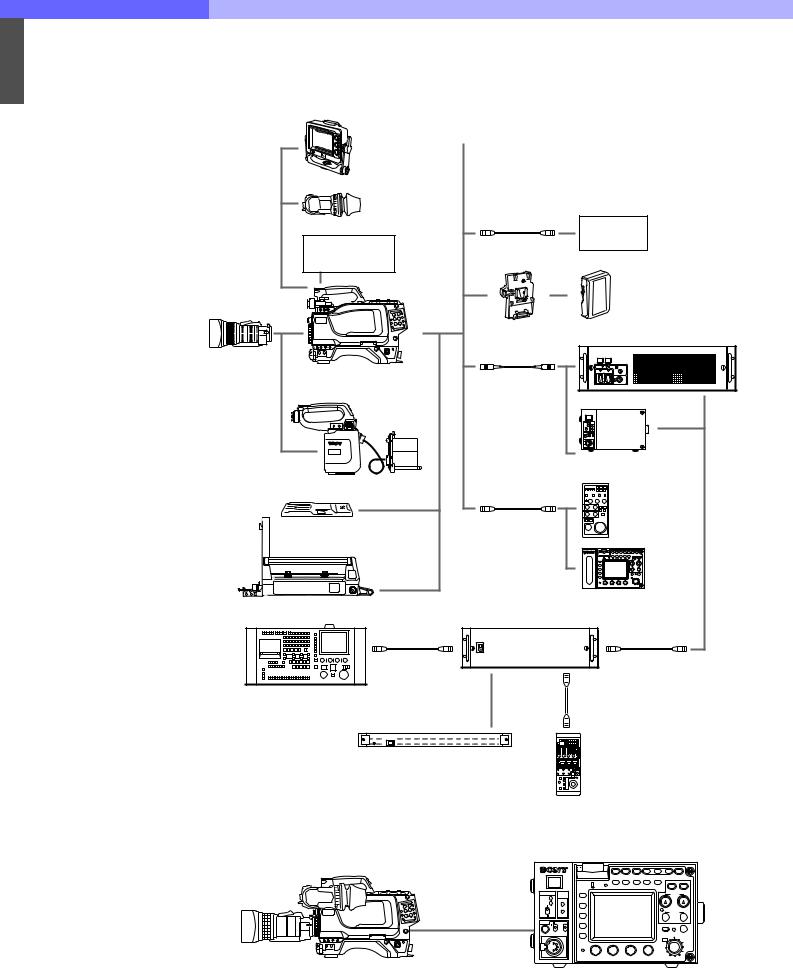
Figure 2-1: HDC-900/950 System Configuration
portable model is designed for full integration into an HDC-900 studio system, as well as being used as a standalone acquisition camera.
In addition to the new peripherals such as HDCU900/950, RCP-750/751, and RM-B750, a variety of key peripherals like the CNU-700 and CNU-500 Camera Command Network Units help users to easily expand/ upgrade their systems.
REMOTE CONTROL PANEL
RCP-750 RCP-751 |
|
|
CCA-5 CABLE |
CCA-5 CABLE |
|
REMOTE |
MASTER SETUP UNIT |
MASTER SETUP UNIT |
CONTROL PANEL |
MSU-700A |
MSU-750 |
CCA-5 CABLE |
CCA-5 CABLE |
|
|
|
|
|
CAMERA COMMAND NETWORK UNIT |
|||
RCP-700 RCP-701 |
||||||||
CNU-700/500 |
||||||||
|
|
|
|
|
||||
|
|
|
|
|
|
|
|
|
|
|
|
|
|
|
|
|
|
|
|
|
|
|
|
|
|
|
CCA-5 CABLE |
CCA-5 CABLE |
CCA-5 CABLE |
|
CAMERA CONTROL UNIT |
|
CAMERA CONTROL UNIT |
CAMERA CONTROL UNIT |
HDCU-900 |
|
HDCU-900 |
HDCU-950 |
HKCU-901 |
|
VIDEO SELECTOR |
HKCU-951 |
|
HKCU-902 |
|
|||
|
VCS-700 |
|||
HKCU-903 |
|
HKCU-953 |
||
|
|
|
||
HKCU-904 |
PIX |
|
|
PIX |
|
|
|
||
|
WF |
WF |
PIX |
WF |
|
|
|
||
|
FIBER CABLE |
|
|
FIBER CABLE |
MULTI FORMAT |
2" VF |
|
ELECTRONIC VIEWFINDER |
HDVF-20A |
MULTI FORMAT |
HDVF-700A |
|
LCD COLOR VIEWFINDER |
|
|
HDVF-C750W |
STUDIO ZOOM LENS |
ENG/EPP LENS |
COLOR VIDEO CAMERA |
|
COLOR VIDEO CAMERA |
MULTI FORMAT |
HDC-900 |
MULTI FORMAT |
HDC-950/930 |
|
|
|
LCD COLOR VIEWFINDER |
|
|
LCD COLOR VIEWFINDER |
|
|
|
|
HDVF-C750W |
|
|
HDVF-C700W |
|
|
|
|
|
SCRIPT HOLDER |
STUDIO ZOOM LENS |
LARGE LENS ADAPTER |
BKP-7911 |
|
CA-905L |
7-TYPE
VIEWFINDER
SADDLE
BKP-9057
MULTI FORMAT |
MULTI FORMAT |
ELECTRONIC VIEWFINDER |
LCD COLOR VIEWFINDER |
HDVF-700A |
HDVF-C700W |
HDC-900/950/930 Series Product Information Manual |
Chapter 2 Total System 14 |

2 |
Figure 2-2: Optional Accessories for the HDC-900 |
|
|
|
|
|
HDVF-700A 7-Type Viewfinder |
HFH-770 Outdoor Hood |
|
(with standard hood) |
(sold separately) |
|
Front cover (supplied) |
|
|
|
HDVF-C700W |
|
|
6-Type Viewfinder |
HDC-900, HDC-900/L
HD Color Video Camera
Zoom lens
BKP-7911 Script Holder
(with Light)
HDCU-900
HD Camera Control Unit
Optical Fiber Cable (option)
V-Shaped wedge (supplied with tripod)
Tripod
HDC-900/950/930 Series Product Information Manual |
Chapter 2 Total System 15 |
2 |
Figure 2-3: Optional Accessories for the HDC-950/930 |
|
HDVF-C750W |
|
|
CAC-6 Return |
HD Electronic |
|
|
Video Selector |
|
|||
Viewfinder |
|
|
|
|
|
|
HDVF-20A
HD Electronic
Viewfinder
HDCZ-10/25
Connection Cable
HD VTR |
HDW-250, etc. |
BKW-401
Viewfinder
Rotation Bracket
|
|
|
BP-L60A/L90A |
|
|
|
Battery Pack |
Zoom lens |
|
|
|
|
BKP-L551 |
|
|
|
Battery Adapter |
|
HDCU-900 HD Camera Control Unit |
HDC-950/930 HD |
Optical Fiber Cable |
|
|
Color Video Camera |
|
|
|
|
|
|
|
|
|
|
HDCU-950 |
|
|
|
HD Camera Control Unit |
HKC-T950 |
|
|
|
|
CCA-5 Cable |
|
RM-B150 |
|
|
|
Remote |
VCT-14 Tripod Adapter |
|
|
Contorl Unit |
|
|
|
|
|
|
|
RM-B750 |
CA-905L Large Lens Adapter |
CNU-700 Camera |
|
|
|
|
|
|
CCA-5 Cable |
Command Network Unit |
CCA-5 Cable |
|
(max. 200 meters) |
|
|
(max. 200 meters) |
MSU-700A//750 Master Setup Unit |
|
CCA-5 Cable |
|
|
|
(max. 200 meters) |
|
O I |
|
|
|
HDS-X3400 Multi Bit Rate Routing Switcher |
|
RCP-700 series |
|
|
Remote Control Panel |
||
|
|
|
|
Figure 2-4: HDC-950 Stand-alone System
1 |
|
MEMORY |
|
STICK |
|
POWER |
CABLE |
|
CAM |
ALRAM |
|
OPEN |
FUNCTION |
|
MAIN |
|
|
|
|
|
|
SHORT |
|
|
|
MAINTE |
INCOM MIC ON |
PROD |
NANCE |
OFF |
PRIV |
SCENE |
|
|
|
PGM ENG |
|
|
|
|
PAINT |
PANEL STANDARD MONITOR |
TEST |
BARS CLOSE |
VTR |
||||
ACTIVE |
|
|
|
|
|
START/STOP |
|
5600K |
AUTO |
SKIN |
BLACK |
KNEE |
|
|
|
|
KNEE |
DETAIL |
GAMMA SATURATION |
|
|
|
|
|
|
|
|
|
AWB |
ABB |
|
|
|
|
|
|
WHITE |
|
|
|
|
|
|
ABS |
BLACK |
|
|
|
|
|
|
|
|
||
|
|
|
|
AUTO |
IRIS/MB |
MASTER |
|
|
|
|
|
IRIS |
ACTIVE |
||
|
|
|
|
|
|
|
BLACK |
|
|
|
|
EXT |
|
|
|
|
IRIS |
|
ALARM |
|
REMOTE CONTROL UNIT |
HDC-950/930 + HDVF-20A |
HDCU-950 + RM-B750 Remote Control Unit |
HDC-900/950/930 Series Product Information Manual |
Chapter 2 Total System 16 |

2 2-2. Camera Head
The HDC-900 Series is an outstanding new-generation HD camera with a true multi-purpose system in which many new technologies have been incorporated such as Sony’s ADSP (Advanced Digital Signal Processing), a newly developed 2.2-million pixel CCD and 12-bit A/ D conversion. 12-bit A/D conversion improves gradation analysis by a factor of four compared to 10bit conversion, significantly improving control over picture tonal reproduction, and accuracy of color reproduction. A 600% dynamic range in conjunction with the 12-bit A/D and the superior DSP processing ensure superb processing of overexposed picture information and the handling of specular highlights. Just some of the state-of-the-art features are:
•Optical filter wheels
•Multiple output capability
•Optical fibre digital transmission
•Memory Stick (media card operation)
•Triple skin tone detail
•Adaptive detail control
•Electronic soft focus
•Adaptive highlight control
•Knee saturation
•Multi matrix control
These improvements contribute to an unsurpassed image quality, making the HDC-900 Series a true ‘top- of-the-line’ studio/OB camera.
The HDC-950/930 is the portable version of the HDC-900 and has identical video processing circuitry. Both models have the same signal performance and can be controlled either at the camera head or by remote control through studio system peripherals such as the HDCU-900/HDCU-950 Camera Control Unit, MSU-700A/750 Master Set-up Unit and CNU-700/500 Camera Command Network Units. Because of this design concept, users of the HDC-950/930 have the same features, the same operational performance and the same operational ‘feel’ as the HDC-900 - an optimized solution to meet the needs of high-end users for a companion studio portable camera.
The flexible interfacing of the HDC-900 and HDC950/930 means that they are not only high-end HD broadcasting cameras, but they can also be easily integrated into conventional studio/OB vehicle systems that use earlier BVP-900/700/500 Series cameras.
The HDC-900/950 family has the following features:
High picture quality and high performance
The new 2/3-type 1080 FIT CCD with 2,200,000 pixels, a unique CCD output signal processing circuit, and a 12-bit A/D converter provide high picture quality and excellent performance for the HDC-900 and HDC-950. A high-cost-performance IT type - HDC-930 - is also available.
Newly designed integrated unit (HDC-950/930 only) Low power consumption and high efficiency of heat radiation were -addressed by integrating the camera and camera adapter into a single unit, improving the reliability. In addition, five filter discs each for CC and ND are provided as standard to match the operability of the studio-use HDC-900.
Multiple formats
The HDC-900 and HDC-950 operate with various formats, covering 24PsF, 50i, 25PsF, 30PsF, as well as 60i systems, while the HDC-930 operates with 50i and 60i systems.
Memory Stick*1 operation
The camera is equipped with a Memory Stick drive, which enables setup data storage and software upgrading using Memory Stick media cards.
*1 “Memory Stick” is a trademark of Sony Corporation.
Selection of gamma table
Multiple gamma tables are provided, enabling you to use multiple formats and perform flexible image creation.
Wide variety of detail control functions
Skin tone detail function
Allows control (emphasis or suppression) of the detail level for just a certain hue or chroma area in the image, by creating a detail gate signal from hue color components centered on skin tones. Detail boost frequency control
The boost frequency can be adjusted from 20 MHz to 30 MHz. This allows the detail thickness to be set appropriately for the subject, thus enabling more subtle image expression.
H/V ratio control
The ratio between horizontal and vertical detail can be adjusted.
White/black limiter
The white side and black side detail can be limited independently.
Easy menu-based setting
Selections and settings for shutter speed, ECS, Super EVS mode, viewfinder display items, video gain, safety zone marker*2 or center marker*3, screen size marker, etc. may be made quickly and easily using setup menus displayed on the viewfinder screen or an external monitor.
*2 Safety zone marker: A box-shaped marker displayed on the viewfinder screen which indicates 80%, 90%, 92.5%, or 95% of the total screen area.
*3 Center marker: A cross-shaped marker that indicates the center of the viewfinder screen.
Wide variety of viewfinder display options
Along with items such as operation messages, a zebra pattern*4, a safety zone marker, and a center marker, camera settings may also be displayed on the viewfinder screen using text and symbols. Further, there are other indicators arranged above and below the viewfinder, such as a tally lamp, battery warning indicator, and an indicator to tell that one or more settings are other than standard. This makes it simple to check the status of the camera.
*4 Zebra pattern: A stripe pattern displayed on the viewfinder screen which indicates the portions where the video level is above about 70% or 100%. Used to check the video level of the subject.
Optical digital transmission
The camera uses electro-optical composite cable for 1.5-gigabit digital optical transmission between the camera and a camera control unit.
High-resolution 2-type multi-format viewfinder (HDC950/930 only)
Along with developing the HDC-950, a 2-type multiformat viewfinder HDVF-20A is provided.
Prevention of electrical shock
When the power connection is unsafe, the power supply from the HDCU (Camera Control Unit) will be shut off.
HDC-900/950/930 Series Product Information Manual |
Chapter 2 Total System 17 |
|
|
|
|
|
2 |
Wide variety of input and output connectors |
• Viewfinder connector |
|
• Optical connector |
• Intercom connector |
|
|
• HD SDI output connector |
• Analog audio input connectors |
|
|
|||
|
|
• DC power supply input connector |
• Tracker connector |
|
|
• Prompter signal output connector |
• Test output connector |
|
|
• RCP connector |
• Return control connector |
|
|
• VTR connector |
• AC OUT connector |
|
|
• Lens connector |
• Large lens connector |
2-3. Camera Control Unit
The HDCU-900 Camera Control Unit carries out signal processing and offers an interface for external equipment. By incorporating a optical digital transmission and digital control system, as well as multiple inputs and outputs, the HDCU-900 provides maximum camera performance combined with flexible operation. It has been designed to achieve the highest reliability, afford easy maintenance and allow flexible system configuration.
The HDCU-900 features a down converter to convert HD*1 signals to SD*2, and a return video up converter to convert SD signals to HD, making it usable with standard definition color video cameras as well as high-definition color video cameras. It can be combined with an optional MSU-700A/750 Master Setup Unit or an optional RCP-750/751/700/701 Remote Control Panel to form a camera control system that meets your system needs. Furthermore, a system capable of controlling multiple video cameras can also be -configured - by adding a CNU-700/500 Camera Command Network Unit.
*1 High Definition (HD) signal: A name for 1125-line highdefinition TV signals.
*2 Standard Definition (SD) signal: A name for NTSC/PAL, 525/625 component, or 525/625 composite signals.
The HDCU-950 Camera Control Unit is also available for use with the HDC-950 and HDC-930 cameras. Its compact body and multiple video outputs make this unit ideal for field use. A stand-alone system can be easily configured by attaching the control panel of the RM-B750 Remote Control Unit to the HDCU-950, which allows you to directly operate the connected camera from the HDCU-950.
The HDCU-900 and HDCU-950 camera control units have the following major features:
Multiple video inputs and outputs (HDCU-900 only) The HDCU-900 has four sets of HD-SDI (Serial Digital Interface) signal inputs and outputs, and four sets of SD component SDI signal inputs and outputs. Adding of various optional function boards allows the following signal input and output:
HKCU-901 SD Analog Interface board
This provides the capability of PAL, NTSC, and SD analog component signal input and output.
HKCU-902 HD Analog Interface board
This provides HD analog signal input and output.
HKCU-903 Frame Rate Converter board
This provides 60i-/50i-format output in a 24P Cinema Production system.
HKCU-904 Line Converter board
This provides 720/60P input and output.
Multiple video outputs (HDCU-950 only)
The HDCU-950 has three HD-SDI (Serial Digital Interface) signal outputs (2 regular outputs and 1 monitor output) and two SD component SDI signal outputs. Adding the optional units allows the following signal outputs:
HKCU-951 SD Encoder board
This provides the capability of NTSC (or PAL) SD analog component signal output.
HKCU-953 HD Frame Rate Converter board
This provides 60i-/50i-format HD and SD signal outputs in a 24P Cinema Production system.
Three return video inputs (HDCU-950 only) The HDCU-950 has three return video input connectors, which receive either HD SDI, SD
component SDI or analog VBS signals (mixed input of different signals is not allowed), may be set to 4:3 edge crop, 16:9 squeeze, or letterbox.
External reference signals
The HDCU-900/950 family can be locked to an external reference signal. Either an HD tri-level sync signal or an SD sync (black burst) signal may be used as the reference signal.
Internal down converter
When the system is operating at a 59.94/50 Hz field frequency, HD signals can be converted to SD component SDI signals using the down converter. The output signal aspect ratio may be set to 4:3 edge crop, 16:9 squeeze, or letter box. The down converter has independent image enhancement, gamma control, and matrix ON/OFF features, and can be controlled externally.
Internal up converter
The HDCU-900/950 family has an up converter to allow monitoring of SD signal return video using an HD viewfinder. The aspect ratio of the return video signal may be set to 4:3 edge crop, 16:9 squeeze, or letter box.
Optical digital transmission
The HDCU-900/950 can be connected to a camera with the use of an optical fiber cable (two single-mode optical fiber lines, two power lines, two control lines) for the transmission of digitized video, audio, and control signals. By connecting optical fiber cables, signals can be transmitted up to a maximum of 3000 meters (1.86 miles) when using the HDCU-900 and up to 1200 meters (0.7 mile) using the HDCU-950. The maximum length of the cable supplying power to the camera varies with the camera system configuration and with the type of optical fiber cable.
Safety-oriented power supply
The HDCU-900/950 is designed for safety. When the power is turned on, a low voltage is supplied at first. Only after it has been verified that an appropriate camera is attached, the normal 240 V power supply is activated. The power is not supplied unless a camera is connected via an optoelectric cable.
Also, the HDCU-900/950 is equipped with an alarm indicator to warn of open or short circuits in the cable.
HDC-900/950/930 Series Product Information Manual |
Chapter 2 Total System 18 |

|
|
|
|
2 |
Wide range of audio functions |
|
The HDCU-900/950 family has connectors for two- |
|
|
channel microphone outputs, a digital audio output, |
|
|
and a program audio input. The family can use an intercom system with two independent channels, and supports four-wire and RTS intercom systems. Further, a Clear-Com system can also be supported.
Note
For information on support for RTS systems, contact a Sony service or sales representative.
Remote control
The levels and phases of the HDCU-900/950 output signals can be controlled remotely by an MSU-700A/ 750 Master Setup Unit.
Microphone volume control
The camera’s microphone volume can be controlled via the MIC REMOTE connector.
Character signal output
The results of the HDCU-900/950 self-diagnosis can be obtained with a text display by an SD character signal output.
Rack mountable
The HDCU-900 can be installed in a full 19-inch rack of 3U height, while the HDCU-950 can be installed in a half 19-inch rack of 3U height in combination with the RMM-301.
Plug-in unit configuration
Internal printed circuit boards used in the HDCU-900/ 950 are designed for easy plug-in and removal for easy inspection and maintenance. Furthermore, the power supply housed in the HDCU-900 is also a plugin type unit.
2-4. Control System
In addition to the MSU-700A/750 Master Set-up Unit and several types of RCP-700 Series Remote Control Panels, the CNU-700 and CNU-500 Camera Command Network Units form the command nerve center for a new concept in a camera control system. A wide selection of control peripherals allows each user to configure the most suitable system to meet a specific operational need. The following are the key peripherals.
Master Set-up Unit (MSU-700A and MSU-750)
The MSU-700A/750 Master Set-up Unit can control up to 6 cameras (up to 12 cameras by using an expansion board - BKP-7930) in combination with the CNU-700 Camera Command Network Unit. The adoption of an EL Touch Panel in the MSU-700A/750 helps to simplify the operation of its sophisticated control system. Data such as scene files can be stored in a world-standard PCMCIA memory card.
Camera Command Network Units (CNU-700 and CNU-500)
The Camera Command Network Units are designed to be the nerve center of the Sony camera control system for the newly developed HDC-900/950/930 family and the conventional BVP-900/700/500 SD Series of cameras. They work as ‘Command Selector’, ‘Command Distributor’ and ‘Command Arbitrator’. These two types of camera command network units give a cost/performance choice. The CNU-500 is suitable for applications with up to six cameras, while the standard six-camera capability of the CNU-700 can be expanded to 12 cameras with use of the BKP7930 optional expansion board. The carefully designed software and the high-speed CPU of both
the CNU-700 and CNU-500 give them a fast response time whatever the system configuration.
Video Selector (VCS-700)
The VCS-700 Video Selector is used to switch composite video monitoring signals from an HDC-900 Series multi-camera system to a picture monitor and waveform monitor. The VCS-700 accepts the video monitoring signal from up to six HDCU-900 or HDCU950 Camera Control Units and switches these signals to two picture monitor outputs and two waveform monitor outputs. The selection of monitoring signals can be controlled by the camera selection buttons on the MSU-700A/750 Master Set-up Unit, or by external control equipment through the D-sub 37-pin I/O port on the VCS-700. For SDI monitoring, the optional BKP7933 S-Bus Interface Board provides connection to a Sony digital routing system.
Remote Control Panels (RCP-700 Series)
There are four ranges of remote control panels for remote control of the HDC-900 Series via the HDCU900/950 Camera Control Unit. For the iris and master black adjustments, each range has two types - joystick control and dial control.
The RCP-750/751 is the newly developed, top of the range for sophisticated operational use, and can be used as a substitute for the MSU-700A/750 Master Setup Unit. The panel is connected to the HDCU-Series Camera Control Unit (or the CNU-Series Camera Command Network Unit, which is connected to the HDCU-Series) by a special cable of up to 200 m (656 ft) in length.
The RCP-700/701 features the basic control items required for daily operation of camera acquisition systems.
2-5. Viewfinders
As well as the HDVF-700A, a high performance 7-type multi-format electronic monochrome viewfinder with extremely high horizontal resolution, the HDVF-C700W 6-type multi-format LCD color viewfinder is also available for the HDC-900. This multi-format LCD color viewfinder is especially convenient for cases where color needs to be identified by the camera operator. For the HDC-950, the HDVF-C750W - a 6-type multiformat LCD color viewfinder and the HDVF-20A - a 2-
type HD monochrome electronic viewfinder are newly designed, which fulfill the requirement for different applications.
All of these models are very compact in size, light in weight and economical in power consumption. The low mounting positions of the HDVF-700A and HDVFC700W provide convenient viewfinder displays aligned as close as possible to the lens axis.
HDC-900/950/930 Series Product Information Manual |
Chapter 2 Total System 19 |

|
|
|
|
2 |
The HDVF-700A has the following features: |
|
Multiscan |
|
|
In addition to the 60i format, formats such as 24PsF |
|
|
and 50i are supported for control signals from the camera.
16:9 display capability
When operated from an external device such as a camera control unit, the screen can be switched between 16:9 and 4:3 display modes.
High resolution
The viewfinder uses a high-resolution cathode-ray tube, providing 800 or more lines of horizontal resolution.
Stable picture
A high-voltage regulation circuit provides a stable image with a minimum of distortion, regardless of screen brightness.
Continuously variable peaking
A continuously variable peaking circuit provides a sharp image, making it easy to focus the camera.
Tally lamps
The viewfinder has red and green tally lamps which light in response to tally signals.
Superior usability
The viewfinder height may be set to one of three positions, and it may be tilted up to 60° upwards or 50° downwards.
Drip-proof construction
The drip-proof design is able to withstand light rain, making the viewfinder well suited to outdoor use.
Studio monitor hood, outdoor hood
The viewfinder may be fitted with a strong, easy-to-use studio hood (supplied), or an outdoor broadcasting (OB) hood with excellent shading ability (option).
Energy-saving design
The viewfinder will accept a wide range of power supply voltage (from 10.5 to 17 volts) with low power consumption (33 watts).
The HDVF-C750W/C700W has the following features:
Compact and lightweight
The viewfinder uses an LCD panel, making it more compact in size and lighter in weight as compared with a CRT viewfinder that has a display of the same size.
Multiscan
In addition to the 60i format, formats such as 24PsF and 50i are supported for control signals from the camera.
High resolution
The high-resolution LCD panel of the viewfinder provides 500 or more lines of horizontal resolution.
Stable picture
The LCD panel provides a stable image without distortion, regardless of screen brightness.
Step-variable peaking
Step-variable peaking circuits provide a sharp image, making it easy to focus the camera.
Tally lamps
The viewfinder has red and green tally lamps which light in response to tally signals.
Superior usability
The height of the HDVF-C750W can be set to one of three positions. It can be tilted up to 90° upwards or 90° downwards, and can be panned up to 90° -to the left or 90° -to the right. The HDVF-C700W can be tilted up to 90° upwards or 50° downwards.
Drip-proof construction
The drip-proof design is able to withstand light rain, making the viewfinder well suited to outdoor use.
Studio monitor hood, outdoor hood
The viewfinder can be fitted with a strong, easy-to-use hood (supplied), or an outdoor hood with excellent shading ability (option).
Energy-saving design
The viewfinder will accept a wide range of power supply voltage (from 10.5 to 17 volts) with low power consumption (10 watts).
The HDVF-20A has the following features.
Multiscan
In addition to the 60i format, formats such as 24PsF and 50i are supported for control signals from the camera.
High-performance CRT
•Quick-start type (The image appears as soon as the camera is turned on.)
•Enhanced resolution
•Reduced flare
Marker indication
When the camera setting allows the center marker or safety zone marker indication, the viewfinder can set the marker indication on or off.
Removable eyepiece
Detaching the eyepiece gives you a clear view of the center of the screen even with your eye away from the viewfinder. You can clean dust from the screen or the mirror by detaching the eyepiece.
Other features
Fitting an optional fog-proof filter (Part No. 1-547-341- 12) over the viewfinder lens prevents breath or vapor condensation on the lens.
2-6. Optional Accessories
For HDC-900 |
|
CRS-3P |
Cradle Suspension |
HDVF-700A |
HD Electronic Viewfinder |
HKC-T950 |
CCD Block Extension |
|
(7-type, monochrome) |
|
Adaptor |
HDVF-C700W |
HD Electronic Viewfinder |
HDVF-20A |
HD Electronic Viewfinder |
|
(6-type, color) |
HDVF-C750W |
HD Electronic Viewfinder |
VFH-770 |
Outdoor Hood |
MSA-8A/16A /32A/64A Memory Stick Media |
|
BKP-7911 |
Script Holder (with script |
|
Card |
|
light) |
VCT-14 |
Tripod adaptor |
CAC-6 |
Return Video Selector |
EX-738(A-8327-351-A) Extension Board |
|
EX-738(A-8327-351-A) Extension Board |
For HDCU-900 |
|
|
For HDC-950/930 |
|
AC power cord: |
USA and Canada: 1- |
BKP-L551 |
Battery Adaptor |
|
551-812-XX |
BKW-401 |
Viewfinder Rotation |
|
Other countries: 1-782- |
|
Bracket |
|
929-XX |
C-74 |
Microphone |
Power cord plug holder:USA and Canada: 2- |
|
CA-905L |
Large Lens Adaptor |
|
990-242-01 |
CAC-6 |
Return Video Selector |
|
Other countries: 3-613- |
CAC-12 |
Microphone holder |
|
640-01 |
HDC-900/950/930 Series Product Information Manual |
Chapter 2 Total System 20 |
|
|
|
|
|
|
|
|
2 |
HKCU-901 |
SD Analog Interface Unit |
CCA-5-10 |
Connection Cable (10 |
|
|
HKCU-902 |
HD Analog Interface Unit |
|
meter/33 feet) |
|
|
|
HKCU-903 |
Frame Rate Converter |
RMM-301 |
Rack Mount Adaptor |
||
|
||||||
|
|
|
Unit |
EX-854(A-8344-228-A) Extension Board |
||
|
|
HKCU-904 |
Line Converter Unit |
EX-893(A-8344-696-A) Extension Board |
||
|
|
CCA-5-3 |
Connection Cable (3 |
For CNU/ MSU/RCP |
|
|
|
|
|
meter/10 feet) |
BKP-7900 |
Extender Board for |
|
|
|
CCA-5-10 |
Connection Cable (10 |
|
CNU-700/500 |
|
|
|
|
meter/33 feet) |
BKP-7930 |
Expansion Board for |
|
|
|
EX-450(A-8314-633-A) Expansion Board |
|
system expansion up to |
||
|
|
For HDCU-950 |
|
|
12 cameras for the CNU- |
|
|
|
AC power cord: |
USA and Canada: 1- |
|
700 |
|
|
|
|
551-812-XX |
BKP-7932 |
BVP-370 Series |
|
|
|
|
Other countries: 1-782- |
|
Interface Board for the |
|
|
|
|
929-XX |
|
CNU-700 |
|
|
|
Power cord plug holder:USA and Canada: 2- |
BKP-7933 |
S-Bus Interface Board |
||
|
|
|
990-242-01 |
|
for CNU-700 |
|
|
|
|
Other countries: 3-613- |
CCA-5 Cables |
8p-8p cables for the |
|
|
|
|
640-01 |
|
CNU-700/500, MSU- |
|
|
|
HKCU-951 |
SD Encoder Unit |
|
700A/750, VCS-700 and |
|
|
|
HKCU-953 |
HD Frame Rate |
|
RCP-700 Series |
|
|
|
|
Converter Unit |
|
CCA-5-3 |
3 m |
|
|
CCA-5-3 |
Connection Cable (3 |
|
CCA-5-10 |
10 m |
|
|
|
meter/10 feet) |
|
CCA-5-30 |
30 m |
2-7. System Setup
2-7-1 Setting the System Format using HDCU-900
The HDCU-900 can support input and output of multiple formats. It can also support various types of user’s format by installing the optional circuit boards.
HDCU-900 and list of optional boards
The slots to which the circuit boards are inserted and the internal switches of the unit differ depending upon the system used. They need to be set according to the system used.
Model name |
Board name |
Board name |
Slot to be installed |
|
(Slots on the front) |
(Slots on the rear) |
|||
|
|
|||
|
|
|
|
|
|
DPR-163 |
SDI-54A |
Fixed to the top most slot |
|
|
|
|
|
|
HDCU-900 |
RC-86 |
DIF-102 |
Second or third slot from the top |
|
|
|
|
|
|
|
AT-141 |
– |
Fixed to the bottom most slot |
|
|
|
|
|
|
SD Analog Interface Unit |
IF-789A*1/789P*2 |
VDA-57 |
Third slot from the top |
|
HKCU-901 |
|
|
|
|
HD Analog Interface Unit |
– |
ADA-59 |
Second or third slot from the top |
|
HKCU-902 |
|
|
|
|
Frame Rate Converter |
FC-83 |
SDI-54B |
Second slot from the top |
|
Unit HKCU-903 |
||||
|
|
|
||
|
|
|
|
|
Line Converter Unit |
LC-41 |
SDI-54C |
Second or third slot from the top |
|
HKCU-904 |
||||
|
|
|
||
|
|
|
|
|
*1 for the USA and Canada. |
|
|
|
|
*2 for the countries other than the USA and Canada. |
|
|
||
Note
•Be sure to install the HKCU-901 of the same -regional location as the HDCU-900.
•When the HKCU-901 is going to be installed, confirm beforehand that the RC-86 board is installed in the second slot from the top on the front side, the DIF102 board or the HKCU-902 is installed in the second slot from the top on the front side.
•When installing the optional boards, be sure to start installation from the second slot from the top on both the front side and rear side. Never install an optional board in the third slot from the top leaving the slots blank without installing the board.
•Be sure to install the HKCU-901/903/904 into the same slot on the front and rear sides.
•Do not install two or more of the same circuit boards at the same time.
HDC-900/950/930 Series Product Information Manual |
Chapter 2 Total System 21 |
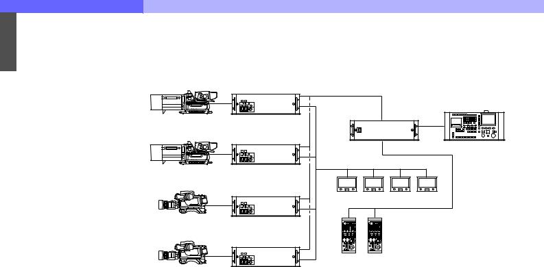
2 |
2-7-1-1 HD System |
|
HDC-900
HDC-900
HDC-950
HDC-950
HDCU-900 |
CNU-700 |
|
|
HKCU-901 |
|
HKCU-902 |
|
HKCU-903 |
|
HKCU-904 |
|
MSU-700A/750
HD-SDI Monitor
HDCU-900
HKCU-901
HKCU-902
HKCU-903
HKCU-904
HDCU-900/950
HKCU-901/951
HKCU-902
HKCU-903/953
HKCU-904
RCP-700/701
RCP-750/751
HDCU-900/950
HKCU-901/951
HKCU-902
HKCU-903/953
HKCU-904
Combination of boards
System format |
Combination of boards (Slots on the front) |
Signal input/output slot |
|||||
|
|
|
|
||||
Second slot from the top |
Third slot from the top |
||||||
|
|
|
|||||
|
|
|
|
|
|
|
|
1080/59.94I SDI |
RC/FC/LC/– |
|
RC/LC/IF*1/– |
|
Top most slot |
|
|
1080/59.94I SDI Film Like |
FC |
|
RC/LC/– |
|
Second slot from the top |
||
|
|
|
|
|
|
|
|
1080/59.94I Analog |
RC*2 |
|
IF/– |
|
Second slot from the top |
||
RC/FC/LC |
|
–*3 |
|
Third slot from the top |
|||
|
|
|
|||||
1080/50I SDI |
RC/FC/LC/– |
|
RC/LC/IF*1/– |
|
Top most slot |
|
|
*1 When installing the IF-789A/789P board (HKCU-901), |
*2 The second slot from the top on the rear side must have the |
||||||
confirm that the RC-86 board is installed in the second slot |
ADA-59 board (HKCU-902) installed. |
|
|||||
from the top. |
|
|
*3 The third slot from the top on the rear side must have the |
||||
|
|
|
ADA-59 board (HKCU-902) installed. |
|
|||
Setting switches |
|
|
|
|
|
|
|
|
|
|
|
|
|
|
|
|
|
|
Switch setting |
|
|
||
|
|
|
|
|
|
|
|
System format |
DPR-163 board (S804 : LOCAL) |
AT-141 |
FC-83 board |
||||
board |
|||||||
|
|
|
|
|
|
||
|
|
|
|
|
|
|
|
|
S805 |
S807 |
S806 |
S603 |
S2 |
S2 |
|
|
|
|
|
|
|
|
|
1080/59.94I SDI |
NOT |
60 |
Intr |
/1001 |
* |
* |
|
|
|
|
|
|
|
|
|
1080/59.94I SDI Film Like |
NOT |
48 |
PsF |
/1001 |
30 |
i |
|
|
|
|
|
|
|
|
|
1080/59.94I Analog |
NOT |
60 |
Intr |
/1001 |
* |
* |
|
|
|
|
|
|
|
|
|
1080/50I SDI |
NOT |
50 |
Intr |
/1000 |
* |
* |
|
|
|
|
|
|
|
|
|
* -NA
HDC-900/950/930 Series Product Information Manual |
Chapter 2 Total System 22 |
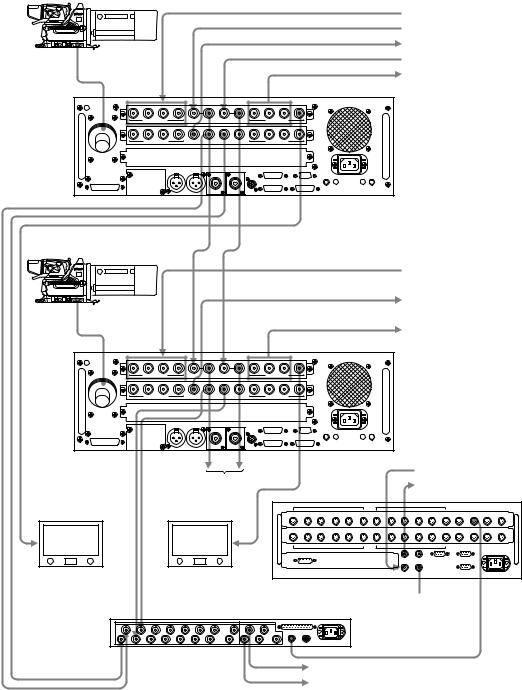
|
|
|
|
|
|
|
|
|
2 |
Figure 2-7-1-1: Example of connection using HDCU-900 (1) – System format: 1080/59.94I SDI |
|
|
|||
|
Required boards |
|
|
|
|
|
|
|
|
|
|
|
|
||
|
|
Slot to be installed |
Board name |
Board name |
|
Remarks |
|
|
|
(Slots on the front) |
(Slots on the rear) |
|
|
||
|
|
|
|
|
|
||
|
|
|
|
|
|
|
|
|
|
Top most slot |
DPR-163 |
SDI-54A |
|
HDCU-900 |
|
|
|
|
|
|
|
|
|
|
|
Second slot from the top |
RC-86 |
DIF-102 |
|
HDCU-900 |
|
|
|
|
|
|
|
|
|
|
|
Third slot from the top |
Blank |
Blank |
|
|
|
|
|
|
|
|
|
|
|
|
SERIAL RET INPUT 1 to 4 |
|
|
HD-SDI RETURN VIDEO SIGNAL |
|
|
REFERENCE IN |
|
|
REFERENCE SIGNAL |
|
|
SYNC OUT (HD) |
|
|
HD REFERENCE SIGNAL |
|
HDC-900 |
PROMPTER IN |
|
PROMPTER SIGNAL |
||
|
||
|
SERIAL OUTPUT 1 to 3 |
|
|
HD-SDI SIGNAL |
1 |
2 |
3 |
4 |
|
|
|
1 |
2 |
3 |
MONI |
|
SERIAL RET INPUT |
|
REFERENCE IN |
PROMPTER IN |
|
SERIAL OUTPUT |
|
|||
1 |
2 |
3 |
4 |
|
|
|
1 |
2 |
3 |
4 |
|
SERIAL RET INPUT |
|
SYNC OUT |
PIX OUT |
WF OUT |
WF MODE |
|
SERIAL OUTPUT |
|
|
HDCU-900 |
|
|
|
|
|
|
|
|
|
|
SERIAL RET INPUT 1 to 4
HD-SDI RETURN VIDEO SIGNAL
SYNC OUT (HD)
HD REFERENCE SIGNAL
HDC-900
SERIAL OUTPUT 1 to 3
HD-SDI SIGNAL
1 |
2 |
3 |
4 |
|
|
|
1 |
2 |
3 |
MONI |
|
SERIAL RET INPUT |
|
REFERENCE IN |
PROMPTER IN |
|
SERIAL OUTPUT |
|
|||
1 |
2 |
3 |
4 |
|
|
|
1 |
2 |
3 |
4 |
|
SERIAL RET INPUT |
|
SYNC OUT |
PIX OUT |
WF OUT |
WF MODE |
|
SERIAL OUTPUT |
|
|
HDCU-900 |
|
|
|
|
|
|
|
|
|
|
Next HDCU-900
SD REFERENCE SIGNAL SD ANALOG VIDEO SIGNAL
HD-SDI Monitor |
HD-SDI Monitor |
|
CNU-700 |
Terminated at 75 Ω
PIX 1 |
PIX 2 |
VCS-700 |
|
WF 1 |
WF 2 |
REMOTE |
|
PIX A
WF A
HDC-900/950/930 Series Product Information Manual |
Chapter 2 Total System 23 |
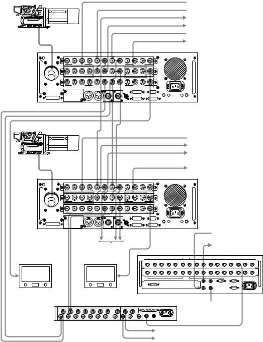
|
|
|
|
|
|
|
|
2 |
Figure 2-7-1-2: Example of connection using HDCU-900 (2) – System format: 1080/59.94I SDI Film Like |
||||
|
Required boards |
|
|
|
|
|
|
|
|
|
|
||
|
|
Slot to be installed |
Board name |
Board name |
Remarks |
|
|
|
(Slots on the front) |
(Slots on the rear) |
|
||
|
|
|
|
|
||
|
|
|
|
|
|
|
|
|
Top most slot |
DPR-163 |
SDI-54A |
HDCU-900 |
|
|
|
|
|
|
|
|
|
|
Second slot from the top |
FC-83 |
SDI-54B |
HKCU-903 |
|
|
|
|
|
|
|
|
|
|
Third slot from the top |
RC-86 |
DIF-102 |
HDCU-900 |
|
|
|
|
|
|
|
|
SERIAL RET INPUT 1 to 4HD-SDI RETURN VIDEO SIGNAL
|
REFERENCE IN |
HD REFERENCE SIGNAL |
|
|
|
||
|
SYNC OUT |
1080/29.97 PsF, tri-level SYNC SIGNAL |
|
|
SYNC OUT |
||
|
1080/59.94I, tri-level SYNC SIGNAL |
||
|
PROMPTER IN |
||
HDC-900 |
PROMPTER SIGNAL |
||
|
SERIAL OUTPUT 1 to 3
HD-SDI SIGNAL
1 |
2 |
3 |
4 |
|
|
|
|
1 |
2 |
3 |
MONI |
|
SERIAL RET INPUT |
|
REFERENCE IN |
PROMPTER IN |
|
|
SERIAL OUTPUT |
|
|||
1 |
2 |
3 |
4 |
|
|
IN |
OUT |
1 |
2 |
3 |
MONI |
|
SERIAL RET INPUT |
|
SYNC OUT |
SYNC OUT |
FRAME REFERENCE |
|
|
SERIAL OUTPUT |
|
||
1 |
2 |
3 |
4 |
|
|
|
|
1 |
2 |
3 |
4 |
|
SERIAL RET INPUT |
|
SYNC OUT |
PIX OUT |
WF OUT |
WF MODE |
|
|
SERIAL OUTPUT |
|
|
HDCU-900 |
|
|
|
|
|
|
|
|
|
|
|
SERIAL RET INPUT 1 to 4
HD-SDI RETURN VIDEO SIGNAL
SYNC OUT
1080/29.97 PsF, tri-level SYNC SIGNAL
SYNC OUT
1080/59.94I, tri-level SYNC SIGNAL
HDC-900
SERIAL OUTPUT 1 to 3 HD-SDI SIGNAL
1 |
2 |
3 |
4 |
|
|
|
1 |
2 |
3 |
MONI |
|
SERIAL RET INPUT |
|
REFERENCE IN |
|
PROMPTER IN |
|
|
SERIAL OUTPUT |
|
|
1 |
2 |
3 |
4 |
|
IN |
OUT |
1 |
2 |
3 |
MONI |
|
SERIAL RET INPUT |
|
SYNC OUT SYNC OUT FRAME REFERENCE |
|
|
SERIAL OUTPUT |
|
|||
1 |
2 |
3 |
4 |
|
|
|
1 |
2 |
3 |
4 |
|
SERIAL RET INPUT |
|
SYNC OUT PIX OUT |
WF OUT WF MODE |
|
|
SERIAL OUTPUT |
|
||
HDCU-900 |
|
|
|
|
|
|
|
|
|
SD REFERENCE |
|
|
|
|
|
|
|
|
|
|
SIGNAL |
Next HDCU-900 |
SD ANALOG VIDEO |
|
SIGNAL |
||
|
HD-SDI Monitor |
|
|
HD-SDI Monitor |
|
|
|
|
|
CNU-700 |
PIX 1 |
PIX 2 |
VCS-700 |
Terminated at 75 Ω |
|
WF 1 |
WF 2 |
|
REMOTE |
|
|
|
|
|
PIX A |
|
|
|
|
WF A |
HDC-900/950/930 Series Product Information Manual |
Chapter 2 Total System 24 |

|
|
|
|
|
|
|
|
|
2 |
Figure 2-7-1-3: Example of connection using HDCU-900 (3) – System format: 1080/59.94I Analog |
|
|
|||
|
Required boards |
|
|
|
|
|
|
|
|
|
|
|
|
||
|
|
Slot to be installed |
Board name |
Board name |
|
Remarks |
|
|
|
(Slots on the front) |
(Slots on the rear) |
|
|
||
|
|
|
|
|
|
||
|
|
|
|
|
|
|
|
|
|
Top most slot |
DPR-163 |
SDI-54A |
|
HDCU-900 |
|
|
|
|
|
|
|
|
|
|
|
Second slot from the top |
RC-86 |
DIF-102 |
|
HDCU-900 |
|
|
|
|
|
|
|
|
|
|
|
Third slot from the top |
Blank |
ADA-59 |
|
HKCU-902 |
|
|
|
|
|
|
|
|
|
|
REFERENCE IN |
|
|
REFERENCE SIGNAL |
|
HDC-900 |
PROMPTER IN |
|
PROMPTER SIGNAL |
||
|
1 |
2 |
3 |
4 |
|
|
|
|
1 |
2 |
3 |
MONI |
|
SERIAL RET INPUT |
|
REFERENCE IN |
PROMPTER IN |
|
SERIAL OUTPUT |
|
||||
1 |
2 |
3 |
4 |
|
|
|
|
1 |
2 |
3 |
4 |
|
SERIAL RET INPUT |
|
SYNC OUT |
PIX OUT |
WF OUT |
WF MODE |
|
SERIAL OUTPUT |
|
||
1 |
2 |
3 |
4 |
|
|
Y/G |
PB/B |
PR/R |
Y/G |
PB/B |
PR/R |
|
|
RET INPUT |
|
SYNC OUT |
PIX OUT |
|
OUT PUT 1 |
|
OUT PUT 2 |
||
HDCU-900 |
|
|
|
|
|
|
|
|
|
|
|
HD Analog Video
HD-ANALOG VIDEO SIGNAL
HD Analog Video
HD-ANALOG VIDEO SIGNAL
SYNC OUT(HD)
HD REFERENCE SIGNAL
RET INPUT 1 to 4
HD ANALOG VIDEO SIGNAL
HDC-900
Next HDCU-900
1 |
2 |
3 |
4 |
|
|
|
|
1 |
2 |
3 |
MONI |
|
SERIAL RET INPUT |
|
REFERENCE IN |
PROMPTER IN |
|
SERIAL OUTPUT |
|
||||
1 |
2 |
3 |
4 |
|
|
|
|
1 |
2 |
3 |
4 |
|
SERIAL RET INPUT |
|
SYNC OUT |
PIX OUT |
WF OUT |
WF MODE |
|
SERIAL OUTPUT |
|
||
1 |
2 |
3 |
4 |
|
|
Y/G |
PB/B |
PR/R |
Y/G |
PB/B |
PR/R |
|
|
RET INPUT |
|
SYNC OUT |
PIX OUT |
|
OUT PUT 1 |
|
OUT PUT 2 |
||
HDCU-900 |
|
|
|
|
|
|
|
|
|
|
|
HD Analog Video
HD-ANALOG VIDEO SIGNAL
HD Analog Video
HD-ANALOG VIDEO SIGNAL
SYNC OUT(HD)
HD REFERENCE SIGNAL
RET INPUT 1 to 4
HD ANALOG VIDEO SIGNAL
Picture Monitor |
Picture Monitor |
|
CNU-700 |
|
Terminated at 75Ω |
PIX 1 |
PIX 2 |
VCS-700 |
|
WF 1 |
WF 2 |
REMOTE |
|
PIX A
WF A
SD ANALOG VIDEO SIGNAL
SD REFERENCE SIGNAL
HDC-900/950/930 Series Product Information Manual |
Chapter 2 Total System 25 |

2 |
2-7-1-2 SD System |
|
HDC-900
HDC-900
HDC-950
HDC-950
PIX/WF
(HKCU-901) VCS-700
HDCU-900 |
CNU-700 |
HKCU-901 |
|
HKCU-902 |
|
HKCU-903 |
|
HKCU-904 |
|
MSU-700A/750
PIX/WF (HDCU-900)
HDCU-900
HKCU-901
HKCU-902
HKCU-903
HKCU-904
HDCU-900/950
HKCU-901/951
HKCU-902
HKCU-903/953
HKCU-904
RCP-700/701
RCP-750/751
HDCU-900/950
HKCU-901/951
HKCU-902
HKCU-903/953
HKCU-904
Combination of boards
System format |
Combination of boards (Slots on the front) |
|
Signal input/output slot |
|||||||||
|
|
|
|
|
|
|
|
|
||||
Second slot from the top |
|
Third slot from the top |
||||||||||
|
|
|
|
|
||||||||
|
|
|
|
|
|
|
|
|
|
|
|
|
525/59.94I SDI |
|
RC |
|
|
|
LC/IF/– |
|
Second slot from the top |
||||
|
|
|
|
|
|
|
|
|
|
|
|
|
525/29.97 PsF SDI Film |
|
FC |
|
|
|
RC |
|
Third slot from the top |
||||
Like |
|
|
|
|
|
|||||||
|
|
|
|
|
|
|
|
|
|
|
|
|
|
|
|
|
|
|
|
|
|
|
|
|
|
NTSC |
|
RC |
|
|
|
IF |
|
Third slot from the top |
||||
|
|
|
|
|
|
|
|
|
|
|
|
|
625/50I SDI |
|
RC |
|
|
|
LC/IF/– |
|
Second slot from the top |
||||
|
|
|
|
|
|
|
|
|
|
|
|
|
PAL |
|
RC |
|
|
|
IF |
|
Third slot from the top |
||||
|
|
|
|
|
|
|
|
|
|
|
|
|
Setting switches |
|
|
|
|
|
|
|
|
|
|
|
|
|
|
|
|
|
|
|
|
|
|
|
|
|
|
|
|
|
|
|
Switch setting |
|
|
|
|
||
|
|
|
|
|
|
|
|
|
|
|
|
|
System format |
DPR-163 board (S804 : LOCAL) |
AT-141 |
|
FC-83 board |
RC-86 |
|||||||
board |
|
board |
||||||||||
|
|
|
|
|
|
|
|
|
|
|
||
|
|
|
|
|
|
|
|
|
|
|
|
|
|
S805 |
S807 |
|
S806 |
|
S603 |
|
S2 |
|
S3 |
S802 |
|
|
|
|
|
|
|
|
|
|
|
|
|
|
525/59.94I SDI |
NOT |
60 |
|
|
Intr |
|
/1001 |
|
* |
|
* |
525 |
|
|
|
|
|
|
|
|
|
|
|
|
|
525/29.97 PsF SDI Film |
NOT |
48 |
|
|
PsF |
|
/1001 |
|
* |
|
* |
525 |
Like |
|
|
|
|
|
|||||||
|
|
|
|
|
|
|
|
|
|
|
|
|
|
|
|
|
|
|
|
|
|
|
|
|
|
NTSC |
NOT |
60 |
|
|
Intr |
|
/1001 |
|
* |
|
* |
525 |
|
|
|
|
|
|
|
|
|
|
|
|
|
625/50I SDI |
NOT |
50 |
|
|
Intr |
|
/1000 |
|
* |
|
* |
625 |
|
|
|
|
|
|
|
|
|
|
|
|
|
PAL |
NOT |
50 |
|
|
Intr |
|
/1000 |
|
* |
|
* |
625 |
|
|
|
|
|
|
|
|
|
|
|
|
|
* -NA
HDC-900/950/930 Series Product Information Manual |
Chapter 2 Total System 26 |
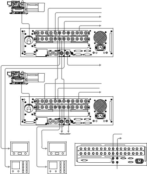
|
|
|
|
|
|
|
|
|
2 |
Figure 2-7-1-4: Example of connection using HDCU-900 (4) - System format: 525/59.94I SDI |
|
|
|||
|
Required boards |
|
|
|
|
|
|
|
|
|
|
|
|
||
|
|
Slot to be installed |
Board name |
Board name |
|
Remarks |
|
|
|
(Slots on the front) |
(Slots on the rear) |
|
|
||
|
|
|
|
|
|
||
|
|
|
|
|
|
|
|
|
|
Top most slot |
DPR-163 |
SDI-54A |
|
HDCU-900 |
|
|
|
|
|
|
|
|
|
|
|
Second slot from the top |
RC-86 |
DIF-102 |
|
HDCU-900 |
|
|
|
|
|
|
|
|
|
|
|
Third slot from the top |
Blank |
Blank |
|
|
|
|
|
|
|
|
|
|
|
|
SERIAL RET INPUT 1 to 4 |
|
|
SD COMPONENT SDI RETURN VIDEO SIGNAL |
|
|
REFERENCE IN |
|
|
REFERENCE SIGNAL |
|
HDC-900 |
SYNC OUT |
|
SD REFERENCE SIGNAL |
||
|
||
|
PROMPTER IN |
|
|
PROMPTER SIGNAL |
|
|
SERIAL OUTPUT 1 to 4 |
|
|
SD COMPONENT SDI SIGNAL |
1 |
2 |
3 |
4 |
|
|
|
1 |
2 |
3 |
MONI |
|
SERIAL RET INPUT |
|
REFERENCE IN |
PROMPTER IN |
|
SERIAL OUTPUT |
|
|||
1 |
2 |
3 |
4 |
|
|
|
1 |
2 |
3 |
4 |
|
SERIAL RET INPUT |
|
SYNC OUT |
PIX OUT |
WF OUT |
WF MODE |
|
SERIAL OUTPUT |
|
|
HDCU-900 |
|
|
|
|
|
|
|
|
|
|
CHARACTER OUTPUT
SD ANALOG VIDEO SIGNAL
SERIAL RET INPUT 1 to 4 HDC-900 SYNC OUT
SERIAL OUTPUT 1 to 4
SD COMPONENT SDI RETURN VIDEO SIGNAL  SD REFERENCE SIGNAL
SD COMPONENT SDI SIGNAL
1 |
2 |
3 |
4 |
|
|
|
1 |
2 |
3 |
MONI |
|
SERIAL RET INPUT |
|
REFERENCE IN |
PROMPTER IN |
|
SERIAL OUTPUT |
|
|||
1 |
2 |
3 |
4 |
|
|
|
1 |
2 |
3 |
4 |
|
SERIAL RET INPUT |
|
SYNC OUT |
PIX OUT |
WF OUT |
WF MODE |
|
SERIAL OUTPUT |
|
|
HDCU-900 |
|
|
|
|
|
|
|
|
|
|
Picture Monitor
Waveform Monitor
Next HDCU-900 |
SD REFERENCE SIGNAL |
|
SD ANALOG VIDEO SIGNAL |
||
Picture Monitor |
||
|
Waveform Monitor
CNU-700
Terminated at 75 Ω
HDC-900/950/930 Series Product Information Manual |
Chapter 2 Total System 27 |

|
|
|
|
|
|
|
|
2 |
Figure 2-7-1-5: Example of connection using HDCU-900 (5) – System format: 525/29.97 PsF SDI Film Like |
||||
|
Required boards |
|
|
|
|
|
|
|
|
|
|
||
|
|
Slot to be installed |
Board name |
Board name |
Remarks |
|
|
|
(Slots on the front) |
(Slots on the rear) |
|
||
|
|
|
|
|
||
|
|
|
|
|
|
|
|
|
Top most slot |
DPR-163 |
SDI-54A |
HDCU-900 |
|
|
|
|
|
|
|
|
|
|
Second slot from the top |
FC-83 |
SDI-54B |
HKCU-903 |
|
|
|
|
|
|
|
|
|
|
Third slot from the top |
RC-86 |
DIF-102 |
HDCU-900 |
|
|
|
|
|
|
|
|
SERIAL RET INPUT 1 to 4
SD COMPONENT SDI RETURN VIDEO SIGNAL
REFERENCE IN
REFERENCE SIGNAL
|
SYNC OUT |
|
HDC-900 |
SD REFERENCE SIGNAL |
|
PROMPTER IN |
||
|
||
|
PROMPTER SIGNAL |
SERIAL OUTPUT 1 to 4
SD COMPONENT SDI SIGNAL
1 |
2 |
3 |
4 |
|
|
|
|
1 |
2 |
3 |
MONI |
|
SERIAL RET INPUT |
|
REFERENCE IN |
PROMPTER IN |
|
|
SERIAL OUTPUT |
|
|||
1 |
2 |
3 |
4 |
|
|
IN |
OUT |
1 |
2 |
3 |
MONI |
|
SERIAL RET INPUT |
|
SYNC OUT |
SYNC OUT |
FRAME REFERENCE |
|
|
SERIAL OUTPUT |
|
||
1 |
2 |
3 |
4 |
|
|
|
|
1 |
2 |
3 |
4 |
|
SERIAL RET INPUT |
|
SYNC OUT |
PIX OUT |
WF OUT |
WF MODE |
|
|
SERIAL OUTPUT |
|
|
HDCU-900 |
|
|
|
|
|
|
|
|
|
|
|
CHARACTER OUTPUT
SD ANALOG VIDEO SIGNAL
|
SERIAL RET INPUT 1 to 4 |
|
SD COMPONENT SDI RETURN VIDEO SIGNAL |
HDC-900 |
SYNC OUT |
SD REFERENCE SIGNAL
SERIAL OUTPUT 1 to 4
SD COMPONENT SDI SIGNAL
1 |
2 |
3 |
4 |
|
|
|
|
1 |
2 |
3 |
MONI |
|
SERIAL RET INPUT |
|
REFERENCE IN |
PROMPTER IN |
|
|
SERIAL OUTPUT |
|
|||
1 |
2 |
3 |
4 |
|
|
IN |
OUT |
1 |
2 |
3 |
MONI |
|
SERIAL RET INPUT |
|
SYNC OUT |
SYNC OUT |
FRAME REFERENCE |
|
|
SERIAL OUTPUT |
|
||
1 |
2 |
3 |
4 |
|
|
|
|
1 |
2 |
3 |
4 |
|
SERIAL RET INPUT |
|
SYNC OUT |
PIX OUT |
WF OUT |
WF MODE |
|
|
SERIAL OUTPUT |
|
|
HDCU-900 |
|
|
|
|
|
|
|
|
|
|
|
Picture Monitor
Waveform Monitor
SD REFERENCE SIGNAL
Next HDCU-900
SD ANALOG VIDEO SIGNAL
Picture Monitor
Waveform Monitor
CNU-700
Terminated at 75 Ω
HDC-900/950/930 Series Product Information Manual |
Chapter 2 Total System 28 |

|
|
|
|
|
|
|
|
2 |
Figure 2-7-1-6: Example of connection using HDCU-900 (6) – System format: NTSC |
|
|
||
|
Required boards |
|
|
|
|
|
|
|
|
|
|
||
|
|
Slot to be installed |
Board name |
Board name |
Remarks |
|
|
|
(Slots on the front) |
(Slots on the rear) |
|
||
|
|
|
|
|
||
|
|
|
|
|
|
|
|
|
Top most slot |
DPR-163 |
SDI-54A |
HDCU-900 |
|
|
|
|
|
|
|
|
|
|
Second slot from the top |
RC-86 |
DIF-102 |
HDCU-900 |
|
|
|
|
|
|
|
|
|
|
Third slot from the top |
IF-789A |
VDA-57 |
HKCU-901 |
|
|
|
|
|
|
|
|
|
RET INPUT 1 to 4 |
|
REFERENCE IN |
|
PIX OUT(For RCP) |
|
PROMPTER IN |
|
WF OUT(For RCP) |
HDC-900 |
WF MODE(For RCP) |
|
|
|
RGB/Component OUT |
|
VBS OUT |
ANALOG RETURN VIDEO SIGNAL REFERENCE SIGNAL
PICTURE MONITOR OUTPUT FOR RCP PROMPTER SIGNAL
WAVEFORM MONITOR OUTPUT FOR RCP WAVEFORM MONITOR MODE FOR RCP ANALOG COMPONENT VIDEO SIGNAL ANALOG COMPOSITE VIDEO SIGNAL
1 |
2 |
3 |
4 |
|
|
|
1 |
2 |
3 |
MONI |
|
SERIAL RET INPUT |
|
REFERENCE IN |
PROMPTER IN |
|
SERIAL OUTPUT |
|
|||
1 |
2 |
3 |
4 |
|
|
|
1 |
2 |
3 |
4 |
|
SERIAL RET INPUT |
|
SYNC OUT |
PIX OUT |
WF OUT WF MODE |
|
SERIAL OUTPUT |
|
||
1 |
2 |
3 |
4 |
|
|
Y/G |
B-Y/B |
R-Y/R |
1 |
2 |
|
|
RET INPUT |
|
SYNC OUT |
PIX OUT |
WF OUT |
OUTPUT |
|
|
VBS OUT |
HDCU-900
WF OUT(For MSU)
PIX OUT(For MSU)
HDC-900
SYNC OUT
RET INPUT 1 to 4
PIX OUT(For RCP)
WF OUT(For RCP)
WF MODE(For RCP)
RGB/Component OUT
VBS OUT
1 |
2 |
3 |
4 |
|
|
|
1 |
2 |
3 |
MONI |
|
SERIAL RET INPUT |
|
REFERENCE IN |
PROMPTER IN |
|
SERIAL OUTPUT |
|
|||
1 |
2 |
3 |
4 |
|
|
|
1 |
2 |
3 |
4 |
|
SERIAL RET INPUT |
|
SYNC OUT |
PIX OUT |
WF OUT WF MODE |
|
SERIAL OUTPUT |
|
||
1 |
2 |
3 |
4 |
|
|
Y/G |
B-Y/B |
R-Y/R |
1 |
2 |
|
|
RET INPUT |
|
SYNC OUT |
PIX OUT |
WF OUT |
OUTPUT |
|
|
VBS OUT |
SD SYNC REFERENCE SIGNAL
ANALOG RETURN VIDEO SIGNAL PICTURE MONITOR OUTPUT FOR RCP WAVEFORM MONITOR OUTPUT FOR RCP WAVEFORM MONITOR MODE FOR RCP ANALOG COMPONENT VIDEO SIGNAL ANALOG COMPOSITE VIDEO SIGNAL
|
HDCU-900 |
PIX 2 |
PIX OUT(For MSU) |
WF 2 |
|
|
WF OUT(For MSU) |
|
Next HDCU-900 |
VCS-700 |
PIX 1 |
WF 1 |
REMOTE |
PIX A
WF A
SD SYNC OUT |
SD SYNC REFERENCE SIGNAL |
|
|
|
SD REFERENCE SIGNAL |
|
SD ANALOG VIDEO SIGNAL |
|
VCS |
CNU-700 |
Terminated at 75 Ω
HDC-900/950/930 Series Product Information Manual |
Chapter 2 Total System 29 |

2 |
2-7-1-3 Progressive and Cinema Production System |
|
HDC-900
HDC-900
HDC-950
HDC-950
HDCU-900 HKCU-901 HKCU-902 HKCU-903 HKCU-904
HDCU-900 HKCU-901 HKCU-902 HKCU-903 HKCU-904
HDCU-900 HKCU-901 HKCU-902 HKCU-903 HKCU-904
HDCU-900 HKCU-901 HKCU-902 HKCU-903 HKCU-904
CNU-700
MSU-700A/750
PIX/WF or SDI Monitor
RCP-700/701
RCP-750/751
Combination of boards
System format |
|
Combination of boards (Slots on the front) |
Signal input/output slot |
||||||||||||
|
|
|
|
|
|
|
|
|
|
|
|
||||
|
Second slot from the top |
|
Third slot from the top |
||||||||||||
|
|
|
|
|
|
||||||||||
|
|
|
|
|
|
|
|
|
|
|
|
|
|
|
|
720/59.94P SDI |
|
|
RC/FC |
|
|
|
LC |
|
|
Third slot from the top |
|||||
|
|
|
|
|
|
|
|
|
|
|
|
|
|
|
|
720/59.94P SDI Film Like |
|
|
|
FC |
|
|
|
LC |
|
|
Third slot from the top |
||||
|
|
|
|
|
|
|
|
|
|
|
|
|
|
|
|
1080/23.98PsF SDI |
|
RC/FC/LC/– |
|
|
|
RC/LC/– |
|
|
Top most slot |
|
|||||
|
|
|
|
|
|
|
|
|
|
|
|
|
|
|
|
1080/24PsF SDI |
|
RC/FC/LC/– |
|
|
|
RC/LC/– |
|
|
Top most slot |
|
|||||
|
|
|
|
|
|
|
|
|
|
|
|
|
|
||
1080/25PsF SDI |
|
RC/FC/LC/– |
|
|
|
RC/LC/IF*4/– |
Top most slot |
|
|||||||
1080/29.97PsF SDI |
|
RC/FC/LC/– |
|
|
|
RC/LC/IF*4/– |
Top most slot |
|
|||||||
1080/30PsF SDI |
|
RC/FC/LC/– |
|
|
|
RC/LC/– |
|
|
Top most slot |
|
|||||
|
|
|
|
|
|
|
|
|
|
|
|
|
|
|
|
525/29.97PsF SDI |
|
|
|
RC |
|
|
|
LC/IF /– |
|
|
Second slot from the top |
||||
|
|
|
|
|
|
|
|
|
|
|
|
|
|
||
*4 When the IF-789A/789P board (HKCU-901) is going to be |
|
|
|
|
|
|
|
|
|||||||
installed, confirm beforehand that the RC-86 board is |
|
|
|
|
|
|
|
|
|
|
|||||
installed in the second slot from the top. |
|
|
|
|
|
|
|
|
|
|
|
|
|
||
Setting switches |
|
|
|
|
|
|
|
|
|
|
|
|
|
|
|
|
|
|
|
|
|
|
|
|
|
|
|
|
|
|
|
|
|
|
|
|
|
|
|
|
Switch setting |
|
|
|
|||
|
|
|
|
|
|
|
|
|
|
|
|||||
System format |
|
DPR-163 board |
|
AT-141 |
|
FC-83 board |
LC-41 |
RC-86 |
|||||||
|
(S804 : LOCAL) |
|
board |
|
board |
board |
|||||||||
|
|
|
|
|
|
|
|||||||||
|
|
|
|
|
|
|
|
|
|
|
|
|
|
|
|
|
|
S805 |
|
S807 |
|
S806 |
|
S603 |
|
S2 |
|
S3 |
S2 |
S802 |
|
|
|
|
|
|
|
|
|
|
|
|
|
|
|
|
|
720/59.94P SDI |
|
540P |
|
* |
|
* |
|
|
/1001 |
|
* |
|
* |
720P |
* |
|
|
|
|
|
|
|
|
|
|
|
|
|
|
|
|
|
NOT |
|
60 |
|
Intr |
|
|
|
|
|
|
|
|
||
|
|
|
|
|
|
|
|
|
|
|
|
||||
|
|
|
|
|
|
|
|
|
|
|
|
|
|
|
|
720/59.94P SDI Film Like |
|
NOT |
|
48 |
|
PsF |
|
/1001 |
|
* |
|
* |
720P |
* |
|
|
|
|
|
|
|
|
|
|
|
|
|
|
|
|
|
1080/23.98PsF SDI |
|
NOT |
|
48 |
|
PsF |
|
/1001 |
|
* |
|
* |
* |
* |
|
|
|
|
|
|
|
|
|
|
|
|
|
|
|
|
|
1080/24PsF SDI |
|
NOT |
|
48 |
|
PsF |
|
/1000 |
|
* |
|
* |
* |
* |
|
|
|
|
|
|
|
|
|
|
|
|
|
|
|
|
|
1080/25PsF SDI |
|
NOT |
|
50 |
|
PsF |
|
/1000 |
|
* |
|
* |
* |
* |
|
|
|
|
|
|
|
|
|
|
|
|
|
|
|
|
|
1080/29.97PsF SDI |
|
NOT |
|
60 |
|
PsF |
|
/1001 |
|
* |
|
* |
* |
* |
|
|
|
|
|
|
|
|
|
|
|
|
|
|
|
|
|
1080/30PsF SDI |
|
NOT |
|
60 |
|
PsF |
|
/1000 |
|
* |
|
* |
* |
* |
|
|
|
|
|
|
|
|
|
|
|
|
|
|
|
|
|
525/29.97PsF SDI |
|
NOT |
|
60 |
|
PsF |
|
/1001 |
|
* |
|
* |
* |
525 |
|
|
|
|
|
|
|
|
|
|
|
|
|
|
|
|
|
* -NA
HDC-900/950/930 Series Product Information Manual |
Chapter 2 Total System 30 |
Loading...