


 Loading...
PROFESSIONAL DISC CAMCORDER
PDW-510/510P PDW-530/530P
OPERATION MANUAL [English] 1st Edition (Revised 1)

WARNING
To prevent fire or shock hazard, do not expose the unit to rain or moisture.
To avoid electrical shock, do not open the cabinet. Refer servicing to qualified personnel only.
This Professional Disc Camcorder is classified as a CLASS 1 LASER PRODUCT.
Laser diode properties
Wavelength: 403 to 410 nm Emission duration: Continuous
Laser output power: 65 mW (max. of pulse peak), 35 mW (max. of CW)
Tekniska data för laserdiod
Våglängd: 403 till 410 nm Emissionslängd: Kontinuerlig
Laseruteffekt: 65 mW (max. för pulstopp), 35 mW (max. för kontinuerlig våg)
Spesifikasjoner laserdiode
Bølgelengde: 403 til 410 nm Strålingens varighet: Kontinuerlig
Laserens effekt: 65 mW (maks stråletoppunkt), 35 mW (maks ved kontinuerlig stråling)
Laserdiodin ominaisuudet
Aallon pituus: 403 - 410 nm Välityksen kesto: Jatkuva
Laserlähdön teho: 65 mW (sykehuipun maks.), 35 mW (jatkuvan aallon maks.)
This label is located inside the outside panel of the unit.
CAUTION
As the laser beam used in this Professional Disc Camcorder is harmful to the eyes, do not attempt to disassemble the cabinet. Refer servicing to qualified personnel only.
CAUTION
The use of optical instruments with this product will increase eye hazard.
CAUTION
Use of controls or adjustments or performance of procedures other than those specified herein may result in hazardous radiation exposure.
VAROITUS!
LAITTEEN KÄYTTÄMINEN MUULLA KUIN TÄSSÄ KÄYTTÖOHJEESSA MAINITULLA TAVALLA SAATTAA ALTISTAA KÄYTTÄJÄN TURVALLISUUSLUOKAN 1 YLITTÄVÄLLE NÄKYMÄTTÖMÄLLE LASERSÄTEILYLLE.
VARNING
OM APPARATEN ANVÄNDS PÅ ANNAT SÄTT ÄN I DENNA BRUKSANVISNING SPECIFICERATS, KAN ANVÄNDAREN UTSÄTTAS FÖR OSYNLIG LASERSTRÅLNING, SOM ÖVERSKRIDER GRÄNSEN FÖR LASERKLASS 1.
For the customers in the USA
This equipment has been tested and found to comply with the limits for a Class B digital device, pursuant to Part 15 of the FCC Rules. These limits are designed to provide reasonable protection against harmful interference in a residential installation. This equipment generates, uses, and can radiate
2

radio frequency energy and, if not installed and used in accordance with the instructions, may cause harmful interference to radio communications.
However, there is no guarantee that interference will not occur in a particular installation. If this equipment does cause harmful interference to radio or television reception, which can be determined by turning the equipment off and on, the user is encouraged to try to correct the interference by one or more of the following measures;
–Reorient or relocate the receiving antenna.
–Increase the separation between the equipment and receiver.
–Connect the equipment into an outlet on a circuit different from that to which the receiver is connected.
–Consult the dealer or an experienced radio/TV technician for help.
You are cautioned that any changes or modifications not expressly approved in this manual could void your authority to operate this equipment.
The shielded interface cable recommended in this manual must be used with this equipment in order to comply with the limits for a digital device pursuant to Subpart B of Part 15 of FCC Rules.
For the customers in the USA
This product contains mercury. Disposal of this product may be regulated if sold in the USA. For disposal or recycling information, please contact your local authorities or the Electronics Industries Alliance (www.eiae.org http:// www.eiae.org ).
For the customers in the USA and Canada
•RECYCLING LITHIUM-ION BATTERIES
Lithium-Ion batteries are recyclable. You can help preserve our environment by returning your used rechargeable batteries to the collection and recycling location nearest you.
For more information regarding recycling of rechargeable batteries, call toll free 1-800-822-8837, or visit http://www.rbrc.org/
Caution: Do not handle damaged or leaking lithium-ion batteries.
•RECYCLING NICKEL METAL HYDRIDE BATTERIES
Nickel metal hydride batteries are recyclable.
You can help preserve our environment by returning your used rechargeable batteries to the collection and recycling location nearest you.
For more information regarding recycling of rechargeable batteries, call toll free1-800-822-8837, or visit http://www.rbrc.org/
Caution: Do not handle damaged or leaking lithium-ion batteries.
For the customers in Europe
This product with the CE marking complies with the EMC Directive (89/336/EEC) issued by the Commission of the European Community.
Compliance with these directives implies conformity to the following European standards:
•EN55103-1: Electromagnetic Interference (Emission)
•EN55103-2: Electromagnetic Susceptibility (Immunity) This product is intended for use in the following Electromagnetic Environment(s):
E1 (residential), E2 (commercial and light industrial), E3 (urban outdoors) and E4 (controlled EMC environment, ex. TV studio).
For the customers in Taiwan only
3

AVERTISSEMENT
Afin d’éviter tout risque d’incendie ou d’électrocution, ne pas exposer cet appareil à la pluie ou à l’humidité.
Afin d’écarter tout risque d’électrocution, garder le coffret fermé. Ne confier l’entretien de l’appareil qu’à un personnel qualifié.
Cet camescope de disques pour professionnels est classé PRODUIT LASER DE CLASSE 1.
Propriétés de la diode laser
Longueur d’onde: 403 à 410 nm Durée d’émission: Continue
Puissance de sortie laser: 65 mW (maxi de crête d’impulsion), 35 mW (maxi d’ondes entretenues)
Cette étiquette est placée à l’intérieur du panneau extérieur de l’appareil.
ATTENTION
Comme le rayon laser utilisé dans ce Camescope de disques pour professionnels est dangereux pour les yeux, ne pas essayer de démonter le coffret. Faire effectuer l’entretien uniquement par un personnel qualifié.
ATTENTION
L’emploi d’instruments optiques avec ce produit augmentera les risques pour les yeux.
ATTENTION
L’emploi de commandes ou ajustements ou l’exécution de procédures autres que celles spécifiées ici peut provoquer une exposition dangereuse au rayonnement.
Pour les utilisateurs aux Etats-Unis et au Canada.
•RECYCLAGE DES ACCUMULATEURS AUX IONS DE LITHIUM
Les accumulateurs aux ions de lithium
sont recyclables.
Vous pouvez contribuer à préserver l’environnement en rapportant les piles usées dans un point de collection et recyclage le plus proche.
Pour plus d’informations sur le recyclage des accumulateurs, téléphonez au numéro gratuit 1-800-822-8837 (Etats-Unis et Canada uniquement), ou visitez http://www.rbrc.org/
Avertissment: Ne pas utiliser des accumulateurs aux ions de lithium qui sont endommagés ou qui fuient.
•RECYCLAGE DES ACCUMULATEURS À HYDRURE MÉTALLIQUE DE NICKEL
Les accumulateurs à hydrure métallique de nickel sont recyclables.
Vous pouvez contribuer à préserver l’environnement en rapportant les piles usées dans un point de collection et recyclage le plus proche.
Pour plus d’informations sur le recyclage des accumulateurs, téléphonez au numéro gratuit 1-800-822-8837 (Etats-Unis et Canada uniquement), ou visitez http://www.rbrc.org/
Avertissment: Ne pas utiliser des accumulateurs aux ions de lithium qui sont endommagés ou qui fuient.
Pour les clients européens
Ce produit portant la marque CE est conforme à la Directive sur la compatibilité électromagnétique (EMC) (89/336/CEE) émise par la Commission de la Communauté européenne.
La conformité à cette directive implique la conformité aux normes européennes suivantes :
EN55103-1 : Interférences électromagnétiques (émission) EN55103-2 : Sensibilité électromagnétique (immunité)
Ce produit est prévu pour être utilisé dans les environnements électromagnétiques suivants :
E1 (résidentiel), E2 (commercial et industrie légère),
E3 (urbain extérieur) et E4 (environnement EMC contrôlé, ex. studio de télévision).
4
WARNUNG
Um Feuergefahr und die Gefahr eines elektrischen Schlages zu vermeiden, darf das Gerät weder Regen noch Feuchtigkeit ausgesetzt werden.
Um einen elektrischen Schlag zu vermeiden, darf das Gehäuse nicht geöffnet werden. Überlassen Sie Wartungsarbeiten stets nur qualifiziertem Fachpersonal.
Dieses Gerät ist als CLASS 1 LASER PRODUCT eingestuft.
Eigenschaften der Laserdiode
Wellenlänge: 403 bis 410 nm Emissionsdauer. Ununterbrochen
Laser-Ausgangsleistung: 65 mW (max. Impulsspitze), 35 mW (max. Dauerstrich)
Dieser Aufkleber befindet sich hinter der Außenabdeckung des Geräts.
VORSICHT
Die Laserstrahlung im Innern ist augenschädlich. Deshalb den Professional Disc Camcorder nicht öffnen/zerlegen. Wartungsarbeiten ausschließlich qualifiziertem Fachpersonal überlassen.
VORSICHT
Der Einsatz von optischen Hilfen verstärkt die Gefahr von Augenschäden.
VORSICHT
Bei Betätigung von Bedienund Einstellteilen oder Ausführung von Bedienvorgängen, die nicht ausdrücklich in dieser Bedienungsanleitung aufgeführt sind, droht u.U. die Einwirkung gefährlicher Laserstrahlung.
GEFAHR
Bei geöffnetem Laufwerk und beschädigter oder deaktivierter Verriegelung tritt ein unsichtbarer Laserstrahl aus.
Direkter Kontark mit dem Laserstrahl ist unbedingt zu vermeiden.
Für Kunden in Europa
Dieses Produkt besitzt die CE-Kennzeichnung und erfüllt die EMV-Richtlinie (89/336/EWG) der EG-Kommission. Angewandte Normen:
•EN55103-1: Elektromagnetische Verträglichkeit (Störaussendung)
•EN55103-2: Elektromagnetische Verträglichkeit (Störfestigkeit),
für die folgenden elektromagnetischen Umgebungen:
E1 (Wohnbereich), E2 (kommerzieller und in beschränktem Maße industrieller Bereich), E3 (Stadtbereich im Freien) und E4 (kontrollierter EMV-Bereich, z.B. Fernsehstudio).
5

ATTENZIONE
Per evitare il pericolo di incendi o scosse elettriche, non esporre l’apparecchio alla pioggia o all’umidità.
Per evitare scosse elettriche, non aprire l’apparecchio.
Per le riparazioni, rivolgersi solo a personale qualificato.
Questo camcorder di dischi professionale è classificato come PRODOTTO LASER CLASSE 1.
Proprietà del laser a diodo
Lunghezza d’onda: da 403 a 410 nm Durata emissione: Continua
Potenza d’emissione del laser: 65 mW (mass. a picco di impulso), 35 mW (mass. di CW)
Questa etichetta si trova all’interno del pannello esterno dell’unità.
CAUTELA
Poiché il raggio laser impiegato in questo camcorder di dischi professionale è dannoso alla vista, non tentare di smontare il rivestimento. Per la manutenzione rivolgersi esclusivamente a personale qualificato.
CAUTELA
L’uso di strumenti ottici con questo prodotto aumenta il rischio per la vista.
CAUTELA
L’uso di comandi o regolazioni o l’esecuzione di procedimenti diversi da quelli specificati in questo manuale possono causare esposizione a radiazioni pericolose.
Per i clienti in Europa
Questo prodotto recante il marchio CE è conforme sia alla direttiva sulla compatibilità elettromagnetica (EMC) (89/336/ CEE) emesse dalla Commissione della Comunità Europea. La conformità a queste direttive implica la conformità alle seguenti normative europee:
EN55103-1: Interferenza elettromagnetica (Emissione) EN55103-2: Sensibilità ai disturbi elettromagnetici (Immunità) Questo prodotto è destinato all’uso nei seguenti ambienti elettromagnetici:
E1 (residenziali), E2 (commerciali e industriali leggeri), E3 (esterni urbani) e E4 (ambienti EMC controllati, ad esempio studi televisivi).
6
ADVERTENCIA
Para evitar el riesgo de incendios o electrocución, no exponga la unidad a la lluvia ni a la humedad.
Para evitar descargas eléctricas, no abra el aparato. Solicite asistencia técnica únicamente a personal especializado.
Este grabador de discos profesional está clasificado como CLASS 1 LASER PRODUCT.
Propiedades del diodo láser
Longitud de onda: 403 a 410 nm Duración de la emisión: Continua
Potencia de salida láser: 65 mW (máx. de pico de pulso), 35 mW (máx. de onda continua)
Esta etiqueta se encuentra en el interior del panel exterior de la unidad.
CAUTION
Como el rayo láser utilizado en este grabador de discos profesional es peligroso para los ojos, no trate de desarmar la caja. Solicite el servicio sólo al personal cualificado.
CAUTION
El uso de instrumentos ópticos con este producto aumentará el peligro a los ojos.
CAUTION
La utilización de controles o ajustes, o la realización de procedimientos no especificados aquí pueden resultar en la exposición a radiación peligrosa.
Para los clientes de Europa
Este producto cumple con las directivas de compatibilidad electromagnética (89/336/CEE) de la Comisión Europea. El cumplimiento de estas directivas implica la conformidad con los siguientes estándares europeos:
•EN55103-1: Interferencia electromagnética (Emisión)
•EN55103-2: Susceptibilidad electromagnética (Inmunidad) Este producto está ha sido diseñado para utilizarse en los
entornos electromagnéticos siguientes:
E1 (zona residencial), E2 (zona comercial e industrial ligera),
E3 (exteriores urbanos), y E4 (entorno con EMC controlada, p. ej., estudio de televisión).
7

8

Table of Contents
Chapter 1 Overview
1-1 Features ............................................. |
12 |
1-1-1 Principal Differences Between the
PDW-510/510P and PDW-530/530P12
1-1-2 Camera Features .............................. |
13 |
|
1-1-3 Features of the Optical Disc Drive |
|
|
|
(VDR) .............................................. |
13 |
1-1-4 Input and Outputs ............................ |
14 |
|
1-1-5 |
Other Functions ............................... |
15 |
1-2 Example of System Configuration .. |
16 |
|
1-3 Precautions ....................................... |
17 |
|
1-4 Using the CD-ROM Manual .............. |
17 |
|
1-4-1 |
CD-ROM System Requirements ..... |
17 |
1-4-2 |
Preparations ..................................... |
17 |
1-4-3 |
Reading the CD-ROM Manual........ |
17 |
Chapter 2 Locations and Functions
of Parts and Controls
2-1 Power Supply .................................... |
19 |
|
2-2 Accessory Attachments ................... |
20 |
|
2-3 Audio Functions................................ |
21 |
|
2-4 |
Shooting and Recording/Playback |
|
|
Functions .......................................... |
24 |
2-5 |
Output Video Operating Section ..... |
31 |
2-6 |
Menu Operating Section................... |
32 |
2-7 Time Code System............................ |
34 |
|
2-8 |
Warnings and Indications ................ |
36 |
2-9 Warnings and Indications on the LCDs
38 |
|
2-9-1 Monochrome LCD........................... |
38 |
2-9-2 Color LCD ....................................... |
39 |
2-10 Indicators in the Viewfinder ........... |
40 |
Chapter 3 Recording and Playback
3-1 Handling Discs .................................. |
42 |
|
3-1-1 Discs Used for Recording and Playback |
||
|
42 |
|
3-1-2 Notes on Handling ........................... |
42 |
|
3-1-3 |
Write-Protecting Discs .................... |
42 |
3-1-4 |
Loading and Unloading a Disc ........ |
43 |
3-1-5 |
Formatting a Disc ............................ |
44 |
3-1-6 |
Handling of Discs When Recording |
|
|
Does Not End Normally (Salvage |
|
|
Function) .......................................... |
44 |
3-2 Recording .......................................... |
46 |
|
3-2-1 |
Basic Procedures.............................. |
46 |
3-2-2 |
Deleting Clips .................................. |
48 |
3-2-3 |
Recording Essence Marks................ |
48 |
3-2-4 Starting a Shoot with a Few Seconds of
|
Pre-Stored Picture Data (Picture Cache |
|
|
Function) .......................................... |
50 |
3-2-5 |
Time-Lapse Video (Interval Rec |
|
|
Function) .......................................... |
52 |
3-2-6 |
Retaking the Most Recent Clip........ |
57 |
3-2-7 |
Auto Clip List Recoding for Automatic |
|
|
Inclusion of Recorded Clips in Clip Lists |
|
|
58 |
|
3-3 Checking Recording and Playback . 59
3-3-1 Normal Playback ............................. |
59 |
|
3-3-2 |
Checking the Last Two Seconds of the |
|
|
Recording — Recording Review ..... |
60 |
3-3-3 |
Checking the Recording on the Color |
|
|
Video Monitor — Playback in Color60 |
|
3-3-4 |
Thumbnail Search............................ |
60 |
3-3-5 |
Clip List Playback............................ |
62 |
3-4 Recording Video Signals from External
Equipment......................................... |
63 |
|
3-4-1 |
Recording a DV Stream From External |
|
|
Equipment ........................................ |
63 |
3-4-2 |
Recording Analog Composite Signals |
|
|
(with the CBK-SC01 Installed)........ |
64 |
3-5 Freezing a Picture During Playback 65
Chapter 4 Scene Selection
4-1 |
Overview............................................ |
66 |
|
4-2 |
Basic Operations .............................. |
67 |
|
|
4-2-1 Creating Clip Lists........................... |
67 |
|
|
4-2-2 Editing Clip Lists............................. |
68 |
|
4-3 |
Clip List Operations.......................... |
71 |
|
|
4-3-1 Displaying the CLIP Menu.............. |
71 |
|
|
4-3-2 Saving the Current Clip List to Disc71 |
||
|
4-3-3 |
Loading a Clip List From Disc Into the |
|
|
|
Current Clip List .............................. |
72 |
|
4-3-4 |
Deleting Clip Lists From Disc......... |
72 |
|
4-3-5 |
Clearing the Current Clip List ......... |
73 |
|
4-3-6 |
Setting the Start Time code of the |
|
Table of Contents |
9 |
|
|

Current Clip List .............................. |
73 |
4-4 Using the PDZ-1 Proxy Browsing |
|
Software ............................................ |
74 |
Chapter 5 Adjustments and Settings for Recording
5-1 Setting the Recording Format (PDW-
530/530P only) .................................. |
75 |
5-1-1 Setting the Video Recording Format75 |
|
5-1-2 Setting the Audio Recording Format76 |
|
5-2 Adjusting the Black Balance and the |
|
White Balance................................... |
77 |
5-2-1 Adjusting the Black Balance ........... |
77 |
5-2-2 Adjusting the White Balance........... |
78 |
5-3 Setting the Electronic Shutter ......... |
81 |
5-3-1 Shutter Modes.................................. |
81 |
5-3-2 Selecting the Shutter Mode and Shutter |
|
Speed................................................ |
81 |
5-4 Changing the Reference Value for |
|
Automatic Iris Adjustment............... |
84 |
5-5 Adjusting the Audio Level................ |
86 |
5-5-1 Manually Adjusting the Audio Levels of |
|
the Audio Inputs From the AUDIO IN |
|
CH1/CH2 Connectors ...................... |
86 |
5-5-2 Manually Adjusting the Audio Level of |
|
the Front Microphone ...................... |
87 |
5-5-3 Recording Audio on Channels 3 and 4 |
|
88 |
|
5-6 Setting the Time Data ....................... |
89 |
5-6-1 Setting the Time Code ..................... |
89 |
5-6-2 Saving the Actual Time in the Time |
|
Code ................................................. |
89 |
5-6-3 Setting the User Bits ........................ |
89 |
5-6-4 Synchronizing the Time Code ......... |
90 |
5-7 Setting the Thumbnail Image........... |
92 |
Chapter 6 File Operations
6-1 |
Overview ............................................ |
93 |
|
|
6-1-1 |
Directory Structure .......................... |
93 |
|
6-1-2 |
File Operation Restrictions.............. |
94 |
6-2 |
File Access Mode File Operations... |
96 |
|
6-3 |
FTP File Operations .......................... |
98 |
|
|
6-3-1 |
Command List ............................... |
100 |
Chapter 7 Menu Displays and
Detailed Settings
7-1 Menu Organization and Operation 105
7-1-1 Menu Organization ........................ |
105 |
7-1-2 Displaying Menus.......................... |
106 |
7-1-3 Basic Menu Operations.................. |
106 |
7-1-4 Editing the USER Menu ................ |
108 |
7-2 Status Display on the Viewfinder |
|
Screen ............................................. |
112 |
7-2-1 Layout of the Status Display on the |
|
Viewfinder Screen ......................... |
112 |
7-2-2 Selecting the Display Items ........... |
114 |
7-2-3 Display Modes and Setting Change |
|
Confirmation/Adjustment Progress |
|
Messages ........................................ |
115 |
7-2-4 Setting the Marker Display............ |
116 |
7-2-5 Setting the Viewfinder................... |
116 |
7-2-6 Recording Shot Data Superimposed on |
|
the Color Bars ................................ |
117 |
7-2-7 Setting the Shot ID......................... |
118 |
7-2-8 Displaying the Status Confirmation |
|
Windows ........................................ |
119 |
7-2-9 Confirming the Image of the Return |
|
Video Signal in the Viewfinder ..... |
121 |
7-3 Adjustments and Settings from Menus
122 |
|
|
7-3-1 |
Setting Gain Values for the GAIN |
|
|
Selector Positions........................... |
122 |
7-3-2 |
Selecting the Output Signals.......... |
122 |
7-3-3 Setting the Color Temperature Manually 124
7-3-4 Specifying an Offset for the Auto White
Balance Setting .............................. |
124 |
7-3-5 Assigning Functions to ASSIGN 1/2/3/4
|
Switches ......................................... |
125 |
|
7-3-6 Setting the Date/Time of the Internal |
|||
|
Clock .............................................. |
127 |
|
7-3-7 |
Selecting the Lens File................... |
128 |
|
7-3-8 |
Selecting the Aspect Ratio............. |
128 |
|
7-3-9 |
Setting the CCD Scan Mode.......... |
129 |
|
7-3-10 |
Using UMID Data........................ |
131 |
|
7-3-11 |
Making Network Settings ............ |
133 |
|
7-4 Resetting USER Menu Settings to the
Standard Settings........................... |
135 |
Chapter 8 Saving and Loading User
Setting Data |
|
8-1 Saving and Loading User Files to and |
|
from a “Memory Stick” .................. |
136 |
8-1-1 Handling the “Memory Stick” ....... |
136 |
10 Table of Contents
8-1-2 Saving User Menu Data to the “Memory
|
Stick” ............................................. |
137 |
8-1-3 |
Loading saved data from a “Memory |
|
|
Stick” ............................................. |
139 |
8-2 Saving and Loading Scene Files .. |
141 |
|
8-2-1 |
Saving a Scene File........................ |
141 |
8-2-2 |
Loading Scene Files....................... |
143 |
8-2-3 Resetting the Settings of the Camcorder |
||
|
to the Standard Settings Saved in the |
|
|
Reference File ................................ |
144 |
8-3 Jumping to a File-Related Menu Page When Inserting a “Memory Stick” 145
Chapter 9 Setting Up the Camcorder
9-1 Power Supply .................................. |
147 |
|
9-1-1 |
Using a Battery Pack ..................... |
147 |
9-1-2 Avoiding Breaks in Operation Due to an |
||
|
exhausted Battery........................... |
148 |
9-1-3 |
Using an AC Adaptor .................... |
148 |
9-1-4 |
Using the Anton Bauer Ultralight |
|
|
System............................................ |
148 |
9-2 Adjusting the Viewfinder................ |
149 |
|
9-2-1 Adjusting the Viewfinder Position 149 9-2-2 Adjusting the Viewfinder Focus and
|
|
Screen............................................. |
149 |
|
9-2-3 Detaching the Viewfinder.............. |
150 |
|
|
9-2-4 Moving the viewfinder shoe up ..... |
150 |
|
|
9-2-5 |
Using the BKW-401 Viewfinder |
|
|
|
Rotation Bracket ............................ |
150 |
|
9-2-6 |
Detaching the Eyepiece ................. |
151 |
9-3 |
Mounting the Lens .......................... |
152 |
|
9-4 |
Adjusting the Flange Focal Length153 |
||
9-5 |
Audio Input System ........................ |
153 |
|
|
9-5-1 |
Using the Supplied Microphone .... |
153 |
|
9-5-2 |
Using an External Microphone...... |
154 |
|
9-5-3 Attaching a UHF Portable Tuner (for a |
|
|
UHF Wireless Microphone System)155 |
|
|
9-5-4 Connecting Line Input Audio |
|
|
Equipment...................................... |
157 |
9-6 |
Tripod Mounting.............................. |
158 |
9-7 |
Attaching the Shoulder Strap ........ |
159 |
9-8 |
Adjusting the Shoulder Pad Position.. |
|
|
159 |
|
9-9 |
Putting on the Rain Cover (Not |
|
|
Supplied) ......................................... |
160 |
9-10 Connecting the Remote Control Unit
161
Chapter 10 Maintenance |
|
10-1 Testing the Camcorder Before |
|
Shooting.......................................... |
163 |
10-1-1 Preparations for Testing............... |
163 |
10-1-2 Testing the Camera ...................... |
163 |
10-1-3 Testing the VDR .......................... |
164 |
10-2 Maintenance .................................. |
167 |
10-2-1 Cleaning the Viewfinder.............. |
167 |
10-3 Operation Warnings...................... |
168 |
Appendixes |
|
Specifications........................................ |
171 |
General .................................................... |
171 |
Video Camera Section............................. |
171 |
Optical Disc Drive Section...................... |
172 |
Recommended Additional Equipment .... |
173 |
Menu List ............................................... |
174 |
OPERATION Menu List......................... |
174 |
PAINT Menu List.................................... |
181 |
MAINTENANCE Menu List .................. |
186 |
FILE Menu List ....................................... |
194 |
DIAGNOSIS Menu List.......................... |
196 |
About a “Memory Stick”....................... |
198 |
Glossary................................................. |
200 |
Index....................................................... |
203 |
Table of Contents 11

Overview Chapter 1
1-1 Features
The PDW-510/510P/530/530P is a camcorder for ENG 1) and EFP 2), in which a color video camera using 2/3-inch high-definition CCDs of a 16:9 aspect ratio and a Professional Disc drive are combined integrally. The camera’s CCDs have approximately 1,000,000 picture elements (pixels) (the number of effective pixels: approximately 500,000).
In addition to the well-established high image quality and resistance to vibration, dust, and moisture of the Betacam SP/SX camcorders, this unit adds a range of new functionality exploiting the capabilities of optical discs.
1)ENG: Electronic News Gathering
2)EFP: Electronic Field Production
1-1-1 Principal Differences Between the PDW-510/510P and PDW530/530P
There are the following differences between the PDW510/510P and PDW-530/530P in the specifications of recording format, internal optical filters, and so on.
PDW-510/510P recording format and internal optical filters
Recording |
DVCAM |
Video |
25 Mbps |
format |
compatible |
|
DVCAM 1) format |
|
recording |
|
|
|
Audio |
16 bits, 48 kHz, |
|
|
|
||
|
|
|
4 channels |
|
|
|
|
|
|
Recording |
85 minutes |
|
|
time |
|
|
|
|
|
Optical |
Single integrated filter system for CC (color |
||
filters |
correction) and ND (neutral density) |
||
|
|
|
|
PDW-530/530P recording format and internal optical filters
Recording |
DVCAM |
Video |
25 Mbps |
format |
compatible |
|
DVCAM format |
|
recording |
|
|
|
Audio |
16 bits, 48 kHz, |
|
|
|
||
|
|
|
4 channels |
|
|
|
|
|
|
Recording |
85 minutes |
|
|
time |
|
|
|
|
|
|
MPEG IMX |
Video |
MPEG IMX 2) format |
|
compatible |
|
(4:2:2 high image |
|
recording |
|
quality video |
|
|
|
recording using |
|
|
|
MPEG2 intra |
|
|
|
frames) |
|
|
|
|
|
|
Audio |
16 bits or 24 bits 3), |
|
|
|
48 kHz sampling, |
|
|
|
4 channels |
|
|
|
|
|
|
Recording |
50 Mbps: 45 minutes |
|
|
time |
40 Mbps: 55 minutes |
|
|
|
30 Mbps: 68 minutes |
|
|
|
|
12 1-1 Features

Optical |
Separate CC filters and ND filters; two filters |
filters |
can be used simultaneously |
|
|
1)DVCAM is a trademark of Sony Corporation.
2)MPEG IMX is a trademark of Sony Corporation.
3)For analog audio input, the effective bit length is maximum 20 bits.
The following characteristics are common to the PDW510/510P and PDW-530/530P.
1-1-2 Camera Features
2/3-inch Power HAD EX CCDs
The three high sensitivity, low smear 2/3-inch Power HAD1) EX CCDs provide high image quality which is at the top of its class for a standard definition camcorder.
•The unit is switchable between a 16:9 aspect ratio wide image and 4:3 standard aspect ratio.
•You can select an interlaced scan mode or progressive scan mode (30 fps (frames per second)2) for the PDW510/530, 25 fps for the PDW-510P/530P).
•With the optional CBK-FC01 Pull Down Board installed, a 24 fps3) progressive scan video can be recorded subjected to pull-down, providing imaging quality close to that of film. (PDW-510/530 only)
1)Abbreviation of “Power Hole-Accumulated Diode.” “Power HAD” is a registered trademark of Sony Corporation.
2)More precisely, 29.97 fps
3)More precisely, 23.98 fps
•The TURBO GAIN button enables an instantaneous boost of the video gain to the maximum 48 dB.
1)ATW: Auto Tracing White balance
2)TruEye: “TruEye” is a registered trademark of Sony Corporation.
Freeze mix function
This allows a still image from the previously captured video to be aligned with the video output from the camera. Thus you can adjust the camera position to get exactly the same framing for new shooting.
Wide range of menu settings
The menus provide the following operations, among others.
•Status display, message, and marker display settings
•Camera adjustment settings
•Switch function assignment
•“Memory Stick” operations
You can also assign any settings to the USER menu, to create customized menus.
Saving and recalling settings in a “Memory Stick”
Using an optional “Memory Stick” 1), you can save menu settings for particular shooting conditions, for recall as required.
1) “Memory Stick” is a trademark of Sony Corporation.
Camera signal processing for high quality video
•The 12-bit A/D converter provides high image quality, stability, and reliability.
•The high-performance electronic shutter allows you to select extended clear scan mode (ECS 1)) and high vertical resolution mode (EVS 2)), to obtain clear, highquality video.
1)ECS: Extended Clear Scan
2)EVS: Super Enhanced Vertical Definition System
Shooting functions to cope with different shooting conditions
•A slow shutter function (up to 1/2 second) is provided as a standard feature. This allows noiseless shooting under very poor lighting conditions and a variety of expressive possibilities, such as shots of flowing streams which are smoothed out by afterimages.
•You can easily recall sets of adjustment values from memory, to match the particular lighting conditions.
•The ATW 1) function provides automatic white balance adjustment in response to changing lighting conditions.
•The TruEye TM 2) process yields distortion-free video, even with high intensity colors.
High-functionality viewfinder
The 2-inch monochrome viewfinder allows accurate focusing.
The switch settings, automatic black balance and white balance items, status, warnings and so on appear on the viewfinder screen.
1-1-3 Features of the Optical Disc
Drive (VDR)
Recording and playback in clip units
Each time you start and stop recording, this creates an independent clip.
•During recording, material is always written to unused parts of the disc. Therefore, even when playing back between shooting sessions, there is no danger of inadvertently overwriting the previous recording.
•Immediately after recording, you can delete clips you decide not to keep, allowing efficient use of the available disc capacity.
•During playback, you can check the recorded video and audio by viewing thumbnail images of clips on the disc and jumping instantly to the first frames of other clips.
Overview 1 Chapter
1-1 Features 13

Overview 1 Chapter
•The i.LINK 1) (FAM (File Access Mode)) function allows you to transfer clip files by connecting a computer, or by connecting the unit to a network with the CBK-NC01 Network Adaptor (option).
1) i.LINK is a trademark of Sony Corporation.
Picture cache recording
Video and audio for a maximum of 10 seconds is always held in memory, so that when you start recording, it is possible to record from just before the REC START button was pressed.
Time-lapse video (intermittent recording) function
You can record video intermittently, capturing any number of frames at any desired time interval.
Proxy AV data
•Proxy AV data is low-resolution data with a video bandwidth of 1.5 Mbps and an audio bandwidth of 64 Kbps per channel. This unit records proxy AV data on the Professional Disc whenever MPEG IMX or DVCAM format data is recorded on the main channel.
•Proxy AV data is much smaller in size than the fullresolution IMX or DVCAM data. It can be transferred quickly over computer networks, easily edited in the field with laptop computers, and readily used in a wide variety of applications, such as content management on small-scale servers.
Wide range of metadata recording
In addition to video and audio, various types of additional information can be recorded on the Professional Disc 1) as metadata.
•Essence marks can be added to mark important locations in the video and audio data.
Essence marks can be added manually at any frame by pressing the lens RET button or an assignable button. They can also be added automatically at locations where there is a sudden change in luminance or audio input above a specified threshold.
•The supplied logging software can be used to add titles, comments, and other text data to clips.
•Computer-readable text files can be recorded on the Professional Disc to enable systematic content management.
The ability to search metadata for the required audio and video scenes brings greater efficiency to various stages of the video production process, such as editing, and archiving.
1) Professional Disc is a trademark of Sony Corporation.
Thumbnail search
Thumbnail images of the clips on the disc can be displayed on the LCD panel and in the viewfinder by pressing the THUMBNAIL button. They can also be shown in external video output.
You can check the content of a clip simply by moving the cursor to its thumbnail and pressing the play button.
Scene selection
You can create and play back clip lists of selected clips from the disc, arranged in any order.
One disc can store up to 99 clip lists.
Clip lists make it simple to perform offline editing in the field for later use with full-scale nonlinear editing systems (XPRI 1), etc.).
1) XPRI is a trademark of Sony Corporation.
High reliability under tough operating conditions
With resistance to vibration and dust comparable to tape based camcorders, this unit can be relied on just like a conventional unit.
1-1-4 Input and Outputs
Range of audio inputs and outputs
•A super-cardioid directional monaural microphone with external power supply is supplied as standard equipment. By changing the connector (service component replacement), a stereo microphone can be fitted.
•The optional slot-in type WRR-855A/855B UHF Synthesized Tuner Unit can be installed in the unit.
•The two AUDIO IN connectors (XLR type, 3-pin) on the rear panel of the unit can be switched to line input, microphone input, or + 48V external power, and also to AES/EBU digital audio inputs (maximum 24 bits).
•When audio cables are connected to the two AUDIO IN connectors (XLR type, 3-pin) on the rear panel of the unit, an automatic detection function forces the recording of the audio input signals from these connectors as channels 1 and 2.
•The AUDIO OUT connectors (XLR type, 5-pin) provide two channels of audio output.
 (i.LINK) connector
The i.LINK connector of this unit supports the following two functions.
Input and output of DV streams (AV/C (Audio/ Video Control) mode)
DV streams can be output from this unit and recorded on standard DV equipment. 1)
14 1-1 Features

In the same way, the output from external DV devices (VTRs, nonlinear editors, etc.) can be input to this unit and recorded on Professional Discs. 2)
DV-compliant nonlinear editors may also be connected.
1)In the case of the PDW-530/530P, DV stream output is also possible when the unit is set to IMX recording mode. Audio data is recorded after conversion according to the specifications of this unit.
2)In the case of the PDW-530/530P, this is possible only when the unit is set to DVCAM recording mode.
Computer access to files (File Access Mode)
Use of application software 1) which supports the XDCAM series enables random access to video, audio, and metadata files on Professional Discs, with the ability to display file lists and perform file-based reads and writes.
Files can be transferred at high speed, and thumbnail lists of disc contents can be viewed on computer screens.
1)Such software includes the supplied PDZ-1 Proxy Browsing Software and the XPRI series.
Remote control connectors
By connecting an optional RM-B150/B750 or similar remote control unit, you can control the shooting functions of this unit externally.
Function extension interface
•Installing the optional CBK-SD01 SDI Output Board enables SDI signal output from the VIDEO OUT connectors.
•By installing the optional CBK-SC01 Analog Composite Input Board, a composite video signal input to the GENLOCK connector can be recorded on this unit.
•An extension connector can be attached to the battery attachment on the rear panel, to allow various camera adapters to be fitted.
Network connector (option)
The optional CBK-NC01 Network Adaptor can be installed on this unit to enable connections to computers and networks. This makes it possible to transfer files at high speeds, and to display of lists of the video, audio, and metadata files stored on Professional Discs. Workflows can be improved by the ability to use FTP commands to transfer files to remote locations over networks.
1-1-5 Other Functions
Usability-oriented design
•There is more space around the rear panel connectors than on previous models, making cable connections and switch operations easier.
•The adjustment range of the shoulder pad in the front to rear direction is increased, making it easier to ensure proper balance when using the unit.
2.5-inch color LCD panel
The side of the unit has an LCD that can be switched to show the following images and data.
•Status information, including audio level meters and time code
•Thumbnails of the video recorded on the Professional Disc
•A playback image of the video recorded on the Professional Disc
•The camera image
Monochrome LCD panel
Even when this unit is powered off, the time code, remaining disc capacity, battery capacity, and other status information appears on the monochrome LCD. (This requires either a battery or a DC power supply connected.)
Instant operation assignable switches
Two switches provided on the side panel and on the top of the grip, respectively, can be assigned to any functions, by a menu operation.
Furthermore, the TURBO GAIN button can also be used as an assignable switch.
Alarm function
If a fault is detected on the optical disc drive, or if the disc or battery capacity is low, notication is provided by warning indicators and audible alarms.
SMPTE (PDW-510/530)/EBU (PDW-510P/ 530P) color bars, and 1 kHz reference signal output
Adjustment of a color monitor or external audio device is easy. Color bars for an SNG 1) uplink are also provided.
1) SNG: Satellite News Gathering
Viewfinder height adjustable
In addition to the front to rear and left to right directions, the viewfinder can be adjusted vertically in two steps.
Supports SNMP 1) for maintenance and service (option)
The SNMP-compliant Sony Remote Maintenance and Monitoring Software can be used when the optional CBKNC01 Network Adaptor is installed on this unit. Via a TCP/IP network connection, this software can monitor the hardware status of this unit in real time and record monitoring logs. This allows you to analyze the problem immediately and take the necessary steps whenever a hardware failure is detected.
1) To be supported shortly.
Overview 1 Chapter
1-1 Features 15
Overview 1 Chapter
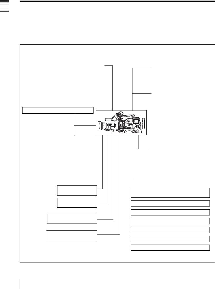
1-2 Example of System Configuration
The diagram below shows a typical configuration of the |
For more information about the fittings, connections, or |
camcorder for ENG and EFP. |
use of additional equipment and accessories, see Chapter |
|
9 as well as the operation manuals for the connected |
|
equipment. |
Viewfinder-related equipment
Name / Purpose |
Magnification |
Part No. |
|
|
|
Fog-proof filter |
– |
1-547-341-11 |
|
|
|
Lens assembly |
–2.8 D to +2.0 D |
A-8262-537-A |
|
|
|
Lens assembly |
–3.6 D to –0.8 D |
A-8262-538-A |
|
|
|
Lens assembly |
–3.6 D to +0.4 D |
A-8267-737-A |
|
|
|
Lens assembly |
–2.4 D to +0.5 D |
A-8314-798-A |
(3 × magnification) |
|
|
|
|
|
Connection through i.LINK interface
Devices with a DV connector (DSR-DU1 etc.)
Camera adaptor
Product |
Model name |
|
|
Input of audio channels |
CA-701 |
3/4 and SDI output |
|
|
|
CCZ (26-pin) output/ |
CA-702/702P |
analog composite/SDI |
|
input |
|
|
|
“Memory Stick”
(see page 198.)
RM-B150/B750 Remote
Control Unit
Video monitor for color image check during shooting
XLR 5-pin connector for stereo microphone (service part)
AC power supply
Product |
|
Model name |
|
|
|
AC Adaptor |
|
AC-550/550CE |
|
|
|
AC Adaptor |
|
AC-DN10 |
|
|
|
Battery |
|
|
|
|
|
Product |
Model name |
|
|
|
|
Battery Charger |
BC-M150/M50 |
|
|
|
|
Battery Pack 1) |
BP-GL65/GL95/ |
|
|
L60S/M100 |
|
1) BP-L40/M50 cannot be used.
Extension board
Product |
Model name |
|
|
SDI Output Board |
CBK-SD01 |
|
|
Composite Input Board |
CBK-SC01 |
|
|
Pull Down Board |
CBK-FC01 2) |
Network Adaptor |
CBK-NC01 |
|
|
2) For PDW-510/530 only
Audio signal source
External microphone ECM-672 or similar microphone
CAC-12 Microphone Holder
Audio equipment
WRR-862 UHF Portable Tuner
WRR-855 series UHF Synthesized Tuner Unit
CCXA-53 audio cable
DMX-P01 Portable Digital Mixer
16 1-2 Example of System Configuration

1-3 Precautions
Use and Storage
Do not subject the unit to severe shocks
The internal mechanism may be damaged or the body warped.
After use
Always turn off the power.
Before storing the unit for a long period
Remove the battery pack.
Use and storage locations
Store in a level, ventilated place. Avoid using or storing the unit in the following places.
•Places subject to temperature extremes
•Very damp places
•Places subject to severe vibration
•Near strong magnetic fields
•In direct sunlight or close to heaters for extended periods
To prevent electromagnetic interference from portable communications devices
The use of portable telephones and other communications devices near this unit can result in malfunctions and interference with audio and video signals.
It is recommended that the portable communications devices near this unit be powered off.
Note on laser beams
Laser beams may damage the CCDs. If you shoot a scene that includes a laser beam, be careful not to let the laser beam be directed into the lens of the camera.
Use at a high temperature
If the unit is used at a high temperature, white flecks may appear on the screen.
About the LCD panels
LCD panels are manufactured with extremely highprecision technology that yields effective pixel rates of 99.99% or higher. However, very rarely, one or more pixels may be permanently dark or permanently lit in white, red, blue, or green.
This phenomenon is not a malfunction. Such pixels have no effect on the recorded data, and the unit may be used with confidence even if they are present.
1-4 Using the CD-ROM
Manual
The supplied CR-ROM includes versions of the Operation Manual for the PDW-510/510P/530/530P in English, Japanese, French, German, Italian, Spanish, and Chinese.
1-4-1 CD-ROM System
Requirements
The following are required to access the supplied CDROM disc.
•Computer: PC with Intel Pentium CPU
-Installed memory: 64 MB or more
-CD-ROM drive: ×8 or faster
•Monitor: Monitor supporting resolution of 800 × 600 or higher
•Operating system: Microsoft Windows Millennium Edition, Windows 2000 Service Pack 2, Windows XP Professional or Windows XP Home Edition
When these requirements are not met, access to the CDROM disc may be slow, or not possible at all.
1-4-2 Preparations
One of the following programs must be installed on your computer in order to use the operation manuals contained on the CD-ROM disc.
•Adobe Acrobat Reader Version 4.0 or higher
•Adobe Reader Version 6.0 or higher
Note
If Adobe Reader is not installed, you can download it from the following URL:
http://www.adobe.com/
1-4-3 Reading the CD-ROM Manual
To read the operation manual contained on the CD-ROM disc, do the following.
1 Insert the CD-ROM disc in your CD-ROM drive.
A cover page appears automatically in your browser. If it does not appear automatically in the browser, double-click the index.htm file on the CD-ROM disc.
2 Select and click the operation manual that you want to read.
This opens the PDF file of the operation manual.
Overview 1 Chapter
1-3 Precautions / 1-4 Using the CD-ROM Manual 17

Overview 1 Chapter
Note
If you lose the CD-ROM disc or become unable to read its content, for example because of a hardware failure, you can do one of the following.
•You can purchase a new CD-ROM disc to replace one that has been lost or damaged. Contact your Sony service representative.
•You can purchase printed versions of the operation manuals (English version). Contact your Sony service representative.
When ordering, be sure to specify the part number of the manual you want.
Part No. |
Models covered |
|
|
3-805-948-0X |
PDW-510/510P/530/530P |
|
|
•Intel and Pentium are registered trademarks of Intel Corporation or its subsidiaries in the United States and other countries.
•Microsoft and Windows are registered trademarks of Microsoft Corporation in the United States and/or other countries.
•Adobe, Acrobat, and Adobe Reader are trademarks of Adobe Systems Incorporated in the United States and/or other countries.
18 1-4 Using the CD-ROM Manual
Locations and Functions |
Chapter 2 |
of Parts and Controls |
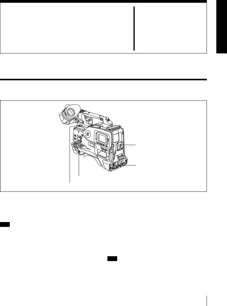
2-1 Power Supply
1 Battery attachment
2 DC IN connector
3 POWER switch
4 LIGHT switch
a Battery attachment
Attach a BP-GL65/GL95/L60S/M100 battery pack. Furthermore, by attaching an AC-DN10 AC Adaptor, you can operate the camcorder from AC power.
Note
For your safety, and to ensure proper operation of the unit, Sony recommends the use of the following battery packs: BP-GL65, BP-GL95, BP-L60S, and BP-M100.
b DC IN connector (XLR type, 4-pin, male)
To operate the camcorder using an AC power supply, connect an AC-550/550CE AC Adaptor with the DC output cable supplied with the adaptor.
c POWER switch
This switch turns the main power supply on and off.
d LIGHT switch
This determines how a video light connected to the LIGHT connector is turned on and off.
AUTO: When the switch on the video light is in the on position, putting the camcorder in recording mode turns the video light on automatically. When using the auto interval recording mode, the video light is automatically turned on immediately before recording starts.
MANUAL: You can turn the video light on or off manually, using its own switch.
Note
To ensure proper operation of the video light with the unit, Sony recommends the use of the following battery packs: BP-GL65, BP-GL95, BP-L60S, and BP-M100.
2-1 Power Supply 19
Controls and Parts of Functions and Locations 2 Chapter
2-2 Accessory Attachments
1 Shoulder strap posts |
2 Light shoe |
3 LIGHT connector
4 Lens mount
5 Lens locking lever
6 Lens mount cap
7 LENS connector
9 Shoulder pad |
8 Tripod mount |
Lens cable clamp
a Shoulder strap posts
Attach the supplied shoulder strap to these posts.
For details, see 9-7 “Attaching the Shoulder Strap” on page 159.
b Light shoe
Attach an optional accessory such as a video light to this shoe.
c LIGHT connector (2-pin, female)
Connect the cable of an Anton Bauer Ultralight System attached to the light shoe. The system operates with lights powered by 12 V, with a maximum power consumption of 50 W.
d Lens mount (special bayonet mount)
Use this for mounting the lens.
e Lens locking lever
After inserting the lens in the lens mount, rotate the lens mount ring with this lever to lock the lens in position.
f Lens mount cap
Remove this cap by pushing up the lens locking lever. When no lens is mounted, keep this cap fitted for protection from dust.
g LENS connector (12-pin)
Fit the lens cable to this connector. Contact your Sony representative for more information about the lens you can use.
h Tripod mount
When using the camcorder on a tripod, attach the tripod adaptor (option).
i Shoulder pad
You can move the shoulder pad forwards or backwards by raising up the shoulder pad locking lever. Do this to ensure the best balance when shooting with the camcorder on your shoulder.
For details, see 9-8 “Adjusting the Shoulder Pad Position” on page 159.
20 2-2 Accessory Attachments
2-3 Audio Functions
8 Built-in speaker
1 Microphone
2 MIC IN connector
3 MIC LEVEL control
4 EARPHONE jack (rear, stereo)
7 ALARM volume control
6 MONITOR volume control
5 MONITOR switch and CH-1/2 / CH-3/4 switch
4 EARPHONE jack (front, monaural)
Audio functions (1)
a Microphone
This is a super-cardioid directional monaural microphone with an external power supply (+48 V) system.
bMIC IN (microphone input) connector (XLR type, 3-pin, female)
Connect the supplied microphone to this connector. A microphone other than the supplied one may also be connected as long as it can operate with the power (+48 V) supplied from this connector.
By fitting a 5-pin connector (service part number: A-1053- 453-A), you can also use a stereo microphone.
c MIC (microphone) LEVEL control
This control adjusts the audio level of the microphone connected to the MIC IN connector.
1)E-E: Abbreviation of “Electric-to-Electric.” In E-E mode, video and audio signals input to the camcorder are output after passing through internal electric circuits only. This can be used to check input signals.
e MONITOR switch and CH-1/2 / CH-3/4 switch
These switches together determine the channel selection for audio monitor output.
MONITOR switch
CH-1/2 / CH-3/4 switch
MONITOR switch and CH-1/2 / CH-3/4 switch
dEARPHONE jack (front) (monaural, minijack) / EARPHONE jack (rear) (monaural/stereo switchable, minijack)
You can monitor the E-E sound 1) during recording and playback sound during playback. Plugging an earphone into the jack automatically cuts off the built-in speaker.
When an alarm is indicated, you can hear the alarm sound through the earphone.
You can use the rear EARPHONE jack for stereo output, by setting the HEADPHONE OUT item in the AUDIO-1 page of the MAINTENANCE menu to “STREO”. You can also connect a monaural earphone to the front jack and a monaural/stereo earphone set to the rear jack simultaneously.
CH-1/2 / CH-3/4 switch:
This determines the pair of audio channels selected with the MONITOR switch.
CH-1/2 position: channels 1 and 2 CH-3/4 position: channels 3 and 4
The signals output from the AUDIO OUT connector and EARPHONE jacks also depend on the setting of this switch.
MONITOR switch:
This selects the audio monitor channels output to the monaural earphone or speaker, depending on the setting of the CH-1/2 / CH-3/4 switch.
Controls and Parts of Functions and Locations 2 Chapter
2-3 Audio Functions 21
Controls and Parts of Functions and Locations 2 Chapter
CH-1/2 CH-3/4 |
MONITOR |
Audio output |
switch |
switch |
|
position |
position |
|
|
|
|
CH-1/2 |
CH-1 |
Audio channel 1 |
|
|
|
|
MIX |
Mix sound of channels 1 and 2 |
|
|
|
|
CH-2 |
Audio channel 2 |
|
|
|
CH-3/4 |
CH-3 |
Audio channel 3 |
|
|
|
|
MIX |
Mix sound of channels 3 and 4 |
|
|
|
|
CH-4 |
Audio channel 4 |
|
|
|
f MONITOR volume control
This control adjusts the speaker or earphone volume for sounds other than the alarm sound. At the minimum position, no sound can be heard.
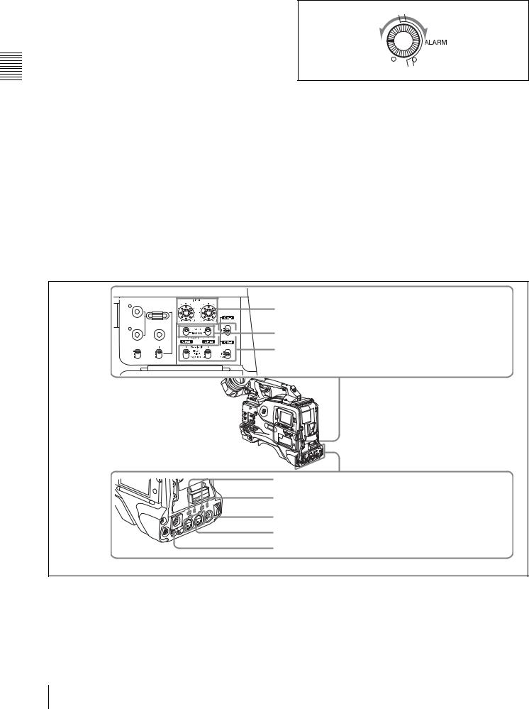
g ALARM volume control
This control adjusts the speaker or earphone alarm volume. At the minimum position, no sound can be heard. However, if in the AUDIO-1 page of the MAINTENANCE menu the MIN ALARM VOL item is set to “SET”, the alarm tone is audible even when this volume control is at the minimum position.
Minimum Maximum
ALARM volume control
h Built-in speaker
The speaker can be used to monitor E-E sound during recording, and playback sound during playback. The speaker also sounds alarms to reinforce visual warnings. The output level of the speaker can be lowered by changing the setting of the SP ATT LEVEL item on the AUDIO-1 page of the MAINTENANCE menu.
If you connect an earphone to the EARPHONE jack, the speaker is automatically muted.
See 10-3 “Operation Warnings” on page 168 for information about alarms.
THUMBNAIL
|
SEL/SET |
|
ESSENCE MARK |
S.SEL |
|
SUB CLIP |
||
|
||
CLIP MENU |
SHIFT |
|
PRESET |
F-RUN |
|
REGEN |
SET |
|
CLOCK |
R-RUN |
9 LEVEL (CH-1/CH-2) controls
0 AUDIO SELECT CH-1/CH-2 switches
qa AUDIO IN CH-1/CH-2 / CH-3/CH-4 switches
qs LINE / AES/EBU / MIC selectors qd +48V/OFF switches
qf AUDIO OUT connector
qg AUDIO IN CH1/CH2 connectors qh DC OUT 12V connector
Audio functions (2)
iLEVEL (CH-1/CH-2) (audio channel-1 and channel-2 recording level) controls
These controls adjust the audio levels of channels 1 and 2 when the AUDIO SELECT switches are set to MANUAL.
22 2-3 Audio Functions

j AUDIO SELECT CH-1/CH-2 (audio channel-1 and channel-2 adjustment method selection) switches
These switches select the audio level adjustment method for each of audio channels 1 and 2.
AUTO: Select this setting for automatic adjustment. MANUAL: Select this setting for manual adjustment.
kAUDIO IN CH-1/CH-2 / CH-3/CH-4 (audio input selection) switches
AUDIO IN CH-1/CH-2 switches
These switches select the audio input signals to be recorded on audio channels 1 and 2.
FRONT: The input signal source is the microphone connected to the MIC IN connector.
REAR: The input signal source is the audio equipment connected to the AUDIO IN CH1/CH2 connectors.
WIRELESS: The input signal source is a WRR-855A/ 855B UHF Synthesized Tuner Unit (option).
AUDIO IN CH-3/CH-4 switches
These switches select the audio input signals to be recorded on audio channels 3 and 4.
F (front): The input signal source is the microphone connected to the MIC IN connector.
R (rear): The input signal source is the audio equipment connected to the AUDIO IN CH1/CH2 connectors.
W (wireless): The input signal source is a WRR-855A/ 855B UHF Synthesized Tuner Unit.
With a CA-701 Camera Adaptor (option) connected to the camcorder, you can record separate sounds on audio channels 3 and 4.
l LINE /AES/EBU / MIC selectors
These select the audio source of the audio input signals input to the AUDIO IN CH1/CH2 connectors.
LINE: Line input audio equipment AES/EBU: AES/EBU format audio signal MIC: Microphone input
Note
When these switches are in the MIC position, and the +48V switch described below is on, if you inadvertently connect any audio device other than a microphone to the AUDIO IN CH1/CH2 connectors, the device may be damaged.
m +48V/OFF switches
Select either of the following positions for the microphones to be connected.
+48V: For a microphone to use an external power supply OFF: For a microphone to use an internal power supply
nAUDIO OUT (audio output) connector (XLR type, 5-pin, male)
This connector outputs the audio signals recorded on audio channels 1 and 2 or audio channels 3 and 4.
The MONITOR CH-1/2 / CH-3/4 switches allow you to select the audio signal to be monitored.
oAUDIO IN CH1/CH2 (audio channel-1 and channel-2 input) connectors (XLR type, 3-pin,
female)
These are audio input connectors for channels 1 and 2 to which you can connect audio equipment or a microphone. When the LINE / AES/EBU / MIC selector is set to AES/ EBU, the CH1 connector is used for channel-1 and -2 inputs, and the CH2 connector, for channel-3 and -4 inputs.
pDC OUT 12 V (DC power output) connector (4-pin, female)
This connector supplies power for a WRR-862 UHF Portable Tuner (option). Do not connect any equipment other than the UHF portable tuner.
Controls and Parts of Functions and Locations 2 Chapter
2-3 Audio Functions 23
Controls and Parts of Functions and Locations 2 Chapter
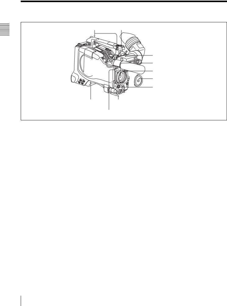
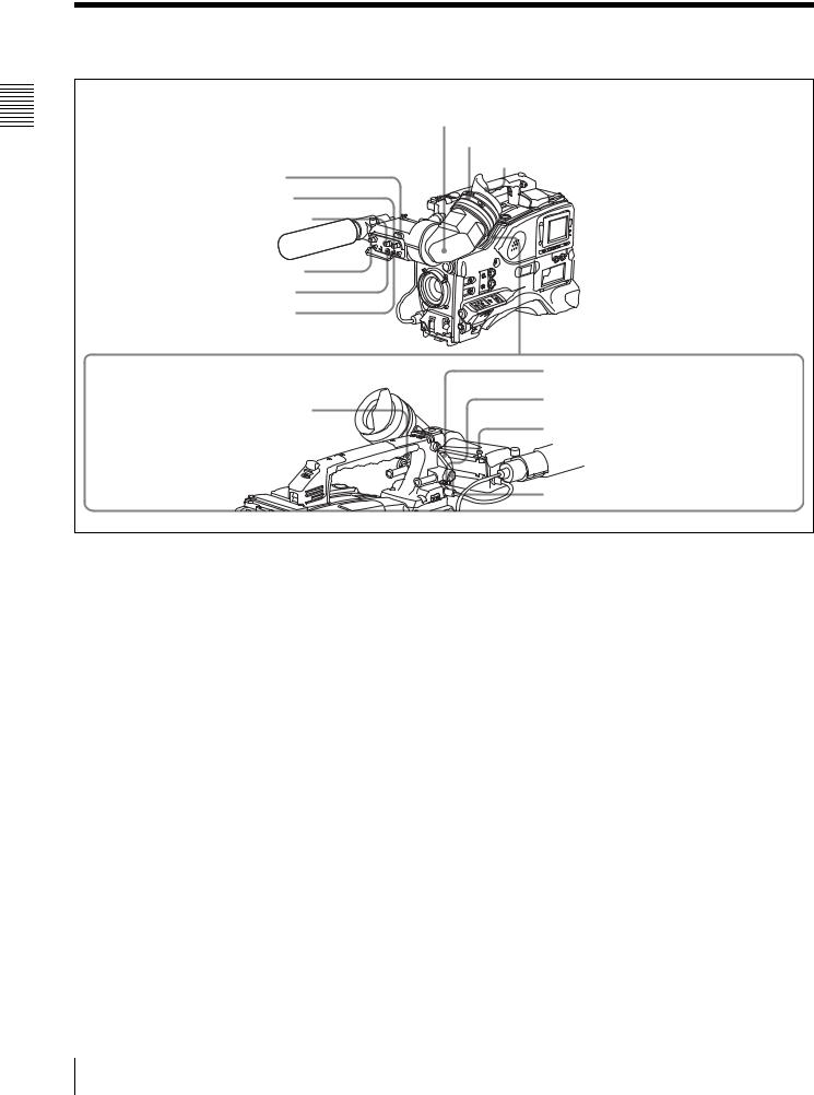
2-4 Shooting and Recording/Playback Functions |
7 Viewfinder |
8 Diopter adjustment ring |
Eyecup |
1 Tally indicator |
2 BRIGHT control |
3 CONTRAST control |
4 PEAKING control |
5 ZEBRA switch |
6 TALLY switch |
0 Viewfinder left-right positioning ring |
qa Camera operator tally indicator |
9 Viewfinder front-rear positioning lever |
qs Viewfinder stopper |
qd LOCK knob |
Shooting and recording/playback functions (1)
a Tally indicator
Setting the TALLY switch to HIGH or LOW enables this indicator. The indicator lights during recording on the VDR (video disc recorder). Like the REC indicator in the viewfinder, it flashes to indicate a problem. You can set the indicator brightness with the TALLY switch.
b BRIGHT (brightness) control
This control adjusts the picture brightness on the viewfinder screen. It has no effect on the camera output signal.
c CONTRAST control
This control adjusts the picture contrast on the viewfinder screen. It has no effect on the camera output signal.
d PEAKING control
This control adjusts the sharpness of the picture on the viewfinder screen to make focusing easier. It has no effect on the camera output signal.
e ZEBRA switch
This switch controls the zebra pattern on the viewfinder screen.
ON: The zebra pattern 1) is displayed and stays. OFF: No zebra pattern is displayed.
MOMENT: The zebra pattern is displayed and stays for 5 to 6 seconds.
The zebra pattern is factory set to indicate picture areas where the video level is approximately 70%.You can use the setup menu to change the setting so that areas where the video level is 100% and above are also displayed at the same time.
For information about how to change the zebra pattern setting in the setup menu, see 7-2-5 “Setting the Viewfinder” on page 116.
1)The zebra pattern aids in manual iris adjustment by indicating areas of the picture where the video level is approximately 70% and 100% and above.
f TALLY switch
This switch controls the tally indicator, setting its brightness (HIGH or LOW) or turning it off. HIGH: The tally indicator brightness is high. OFF: The tally indicator is disabled.
LOW: The tally indicator brightness is low.
24 2-4 Shooting and Recording/Playback Functions

g Viewfinder
The viewfinder lets you view the image in black and white while shooting, recording or playing back. It also displays various warnings and messages related to the settings or operating conditions of the camcorder, a zebra pattern, safety zone marker 1), and center marker 2).
1)The safety zone marker is a rectangle indicating the effective picture area.
2)The center marker indicates the center of the picture with a crosshair.
For details, see 7-2-4 “Setting the Marker Display” on page 116.
h Diopter adjustment ring
j Viewfinder left-right positioning ring
Loosen this ring to move the viewfinder sideways.
k Camera operator tally indicator
This indicator lights while the camcorder is recording. Slide the window open when you shoot with your eye away from the viewfinder. This indicator flashes when the battery level is running low or the disc is almost full.
l Viewfinder stopper
Pull up this stopper to detach the viewfinder from the camera.
Use this ring to adjust the viewfinder image for your vision.
i Viewfinder front-rear positioning lever
To adjust the viewfinder position in the front-rear direction, loosen this lever and the LOCK knob. After adjustment, retighten this lever and the LOCK knob.
m LOCK knob
To adjust the viewfinder position in the front-rear direction, loosen this knob and the viewfinder front-rear positioning lever. After adjustment, retighten this knob and the viewfinder front-rear positioning lever.
ws ASSIGN 3/4 switches
qf FILTER selector |
wa TURBO GAIN button |
|
|
qg ASSIGN. 1/2 switches |
w; WHITE BAL switch |
|
|
qh SHUTTER selector |
ql OUTPUT/DCC selector |
|
|
qj AUTO W/B BAL switch |
qk GAIN selector |
Shooting and recording/playback functions (2)
n FILTER selector
Use this selector to select the most appropriate filter to match the light source illuminating the subject.
When this selector is used with the display mode set to 3, the new setting appears on the viewfinder screen for about 3 seconds. (e.g.: FILTER: 3)
The PDW-510/510P has one switchable filter, and the PDW-530/530P has two switchable filters.
The relationships between the selector settings and filter selections as well as examples of filters for different shooting conditions are as follows.
For the PDW-510/510P
FILTER selector setting and filter selection
FILTER selector setting |
Filter selection |
|
|
1 |
3200 K |
|
|
2 |
5600 K + 1/8 ND |
3 |
5600 K |
|
|
4 |
5600 K + 1/64 ND |
Examples of shooting conditions and appropriate filters
Shooting condition |
Filter |
|
|
|
|
|
|
Sunrise and sunset; inside studio |
1 |
(3200 K) |
|
|
|
|
|
Clear skies |
2 (5600 |
K + 1/8 ND) |
|
Cloudy or raining |
3 |
(5600 |
K) |
|
|
|
|
Controls and Parts of Functions and Locations 2 Chapter
2-4 Shooting and Recording/Playback Functions |
25 |
|
|

Controls and Parts of Functions and Locations 2 Chapter
Examples of shooting conditions and appropriate filters
Shooting condition |
Filter |
|
|
Very bright conditions such as snow, at |
4 (5600 K + 1/64 ND) |
high altitudes, or at the seashore |
|
For the PDW-530/530P
FILTER selector (outer knob) setting and CC filter selection
FILTER selector (outer knob) setting |
CC filter selection |
|
|
A |
Cross filter 1) |
B |
3200 K |
|
|
C |
4300 K |
|
|
D |
6300 K |
|
|
1)A type of special effect filter. Generates a cross of light on a highlighted portion.
FILTER selector (inner knob) setting and ND filter selection
FILTER selector (inner knob) setting ND filter selection
1 |
Clear |
2 |
1/4 ND |
3 |
1/16 ND |
4 |
1/64 ND |
Examples of shooting conditions and appropriate filters
Shooting condition |
CC filter |
ND filter |
||
|
|
|
|
|
Sunrise and sunset; inside |
B (3200 K) |
1 |
(clear) |
|
studio |
|
|
|
|
|
|
|
||
Clear skies |
C (4300 K) or |
2 (1/4 ND) or 3 |
||
|
D (6300 |
K) |
(1/16 ND) |
|
Cloudy or raining |
D (6300 K) |
1 (clear) or 2 |
||
|
|
|
(1/4 ND) |
|
Very bright conditions such |
C (4300 |
K) or |
3 |
(1/16 ND) or |
as snow, at high altitudes, |
D (6300 |
K) |
4 |
(1/64 ND) |
or at the seashore |
|
|
|
|
o ASSIGN. 1/2 switches
You can assign the desired functions to each of the ASSIGN. 1 switch (push button) and ASSIGN. 2 switch (sliding) on the FUNCTION 1 page of the USER menu.
For details, see 7-3-5 “Assigning Functions to ASSIGN 1/ 2/3/4 Switches” on page 125.
p SHUTTER selector
Set this selector to ON to use the electronic shutter. Push it down to SELECT to switch the shutter speed or mode setting within the range previously set with the setup menu.
When this selector is operated, the new setting appears on the setting change/adjustment progress message display area for about 3 seconds.
For details about the shutter speed and mode settings, see 5-3 “Setting the Electronic Shutter” on page 81.
qAUTO W/B BAL (automatic white/black balance adjustment) switch
This switch activates the white balance and black balance automatic adjustment functions.
WHITE: Automatic adjustment of the white balance. If the WHITE BAL switch is set to A or B, the white balance setting is stored in the corresponding memory. On the PDW-530/530P models with two switchable filters, the memory stores a separate white balance setting for each CC filter setting.
BLACK: Automatic adjustment of the black set and black balance.
r GAIN selector
This selector switches the gain of the video amplifier to match the lighting conditions during shooting. The gains corresponding to the L, M, and H settings can be selected from the setup menu. The factory settings are L = 0 dB, M = 9 dB, and H = 18 dB.
When this selector is adjusted, the new setting appears on the setting change/adjustment progress message display area of the viewfinder screen for about 3 seconds.
For details about setting the gain values, see 7-3-1 “Setting Gain Values for the GAIN Selector Positions” on page 122.
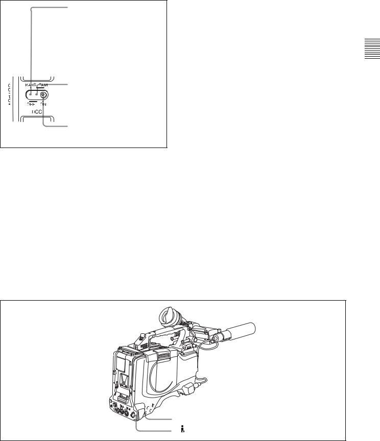
s OUTPUT/DCC (output signal/dynamic contrast control) selector
This selector switches the video signal that is output to the VDR, viewfinder, and video monitor, between the following two.
BARS: Outputs the color bar signal.
CAM: Outputs the video signal from the camera. When this is selected, you can switch DCC 1) on and off with this selector.
1)DCC (Dynamic Contrast Control)
Against a very bright background with the iris opening adjusted to the subject, objects in the background will be lost in the glare. The DCC function will suppress the high intensity and restore much of the lost detail and is particularly effective in the following cases.
•Shooting people in the shade on a sunny day
•Shooting a subject indoors, against a background through a window
•Any high contrast scene
26 2-4 Shooting and Recording/Playback Functions
BARS, DCC OFF
A color bar signal is output and the DCC circuit does not operate. For example, use the setting for the following purposes.
•Adjusting the video monitor
•Recording the color bar signal
CAM, DCC OFF
The video signal from the camera is output, and the DCC circuit does not operate.
CAM, DCC ON
The video signal from the camera is output, and the DCC circuit operates.
OUTPUT/DCC selector
t WHITE BAL (white balance memory) switch
This switch controls the white balance setting. PRST (preset): Adjusts the color temperature
corresponding to the position of the FILTER selector. Use the PRST setting when you have no time to adjust the white balance.
A or B: When the AUTO W/B BAL switch is pushed to WHT, the white balance is automatically adjusted according to the current position of the FILTER selector, and the adjusted value is stored in either memory A or memory B. (There are two memories for each CC filter, allowing a total of eight adjustments to be stored.) When this switch is set to A or B, the camcorder automatically adjusts itself to the stored value corresponding to the current settings of this
switch and the FILTER selector.
You can use the AUTO W/B BAL switch even when ATW 1) is in use.
B (ATW): When this switch is set to B and on the FUNCTION 2 page of the OPERATION menu, “WHITE B CH” is set to “ATW” 1), ATW is activated.
1)ATW (Auto Tracing White Balance)
The white balance of the picture being shot is adjusted automatically for varying lighting conditions.
When this switch is adjusted, the new setting appears on the setting change/adjustment progress message display area of the viewfinder screen for about 3 seconds.
You can assign the ATW ON/OFF function to the ASSIGN 1 switch (push button) on the FUNCTION 1 page of the USER menu.
For details, see 7-3-5 “Assigning Functions to ASSIGN 1/ 2/3/4 Switches” on page 125.
u TURBO GAIN button
When shooting under extremely poor lighting conditions, press the button once to boost the video gain to the value preset on the GAIN SW page of the USER menu (up to 48 dB). To stop boosting the gain, press the button once more.
v ASSIGN 3/4 switches
You can assign the desired functions to each of the ASSIGN 3 switch and ASSIGN 4 switch on the FUNCTION 1 page of the USER menu.
For details, see 7-3-5 “Assigning Functions to ASSIGN 1/ 2/3/4 Switches” on page 125.
Controls and Parts of Functions and Locations 2 Chapter
wf REMOTE connector 


 wg GENLOCK IN connector wd VIDEO OUT connector
 wh TEST OUT connector
wj
Shooting and recording/playback functions (3)
2-4 Shooting and Recording/Playback Functions |
27 |
|
|

Controls and Parts of Functions and Locations 2 Chapter
w VIDEO OUT connector (BNC type)
This connector outputs a composite video signal for a video monitor. With a video monitor connected to this connector, you can monitor the picture being shot by the camera or the picture played back by the VDR. To choose between the composite video signal output and SDI signal output, use the menu. When synchronizing the time code of an external VDR with that of the camcorder, connect this connector to the GENLOCK IN connector of the external VDR.
By installing the CBK-SD01 extension board (not supplied), you can output an SDI signal (supporting embedded audio and the EDH function) from this connector.
For details on how to select the output signal, see 7-3-2 “Selecting the Output Signals” on page 122.
x REMOTE connector (8-pin)
Connect the RM-B150/B750 Remote Control Unit, which makes it possible to control the VDR and camera remotely.
y GENLOCK IN connector (BNC type)
•This connector inputs a reference signal when the camera is to be genlocked or when time code is to be synchronized with external equipment. Use the MAINTENANCE menu to adjust the genlock H-phase (phase of horizontal sync signal) and the sub-carrier phase.
For details, refer to the Maintenance Manual.
•This connector also inputs a return video signal. You can display the return video signal in the viewfinder screen while holding the RET button down with “RETURN VIDEO” set to “ON” on the GENLOCK page of the OPERATION menu.
•This connector also inputs an external analog composite video signal.
When the CBK-SC01 extension board is installed, you can record the external analog composite video signal input to this connector.
z TEST OUT connector (BNC type)
This connector outputs the video signal for a video monitor. The output signal can be selected from composite or RGB. The factory setting is composite, and the setting returns to composite whenever the unit is powered on. Depending on internal board and menu settings, menus, time code, and shot data can be superimposed on the image on the monitor. Like the VIDEO OUT connector, this connector can also be used to synchronize the time code of an external VTR with the time code of the camcorder.
For details on how to select the test output signal, refer to the Maintenance Manual.
wj  (i.LINK) DV IN/OUT S400 connector (6-pin,
IEEE1394 compliant)
Connect to a device supporting the DV format or a computer, using a i.LINK cable.
Notes
•If video and audio signals are not output to an external device connected to the i.LINK DV IN/OUT S400 connector, try disconnecting the i.LINK cable and then reconnecting it, making sure that it is firmly seated.
•When you connect this unit to an external device with a 6-pin i.LINK connector, always power this unit off and disconnect the DC cable from the DC IN connector, or remove the battery pack, before connecting or disconnecting the i.LINK cable.
If you connect or disconnect the i.LINK cable while power is being supplied to this unit, high voltage (8 to 40 V) can flow into this unit from the i.LINK connector of the connected equipment, possibly damaging this unit.
•When you connect this unit to an external device with a 6-pin i.LINK connector, always connect the 6-pin i.LINK connector on the external device first.
28 2-4 Shooting and Recording/Playback Functions
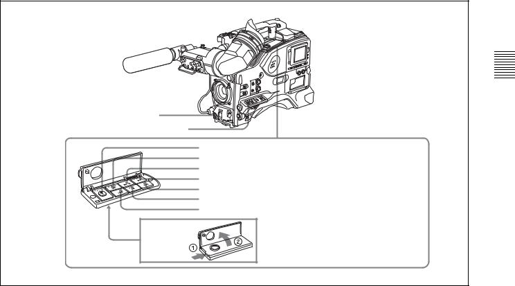
wk REC START button
wl VDR SAVE/STBY connector
|
|
|
E |
|
|
|
|
S |
|
|
|
|
U |
|
|
|
|
A |
|
|
|
/P |
|
|
|
Y |
|
NEXT |
|
A |
|
|
||
L |
|
|
|
|
P |
|
|
|
|
|
|
V |
|
E |
|
R |
|
|
P |
|
|
e; EJECT button and indicator ea F REV button and indicator
es PLAY/PAUSE button and indicator ed F FWD button and indicator
ef NEXT button eg STOP button eh PREV button
Shooting and recording/playback functions (4)
wk REC START button
Press this button to start recording. Press it again to stop recording. The effect is exactly the same as that of the VTR button on the lens.
When the REC SWITCH function is assigned to the ASSIGN 1, 3 or 4 switch (push button), you can use the switch as the REC START button.
wl VDR SAVE/STBY (standby) switch
This switch controls the VDR power mode during pauses in recording.
SAVE: Power saving mode. Although an internal operating sound is recorded as noise when you start recording, power consumption in this mode is less than in standby mode, so that battery life is extended. When the switch is set to SAVE, the SAVE indicator in the viewfinder lights.
STBY: Standby mode. Recording starts as soon as you press the REC START button.
e; EJECT button and indicator
Press this button to eject or load a disc. The indicator flashes while the disc is being ejected.
ea F REV (fast reverse) button and indicator
Plays back at high speed in the reverse direction. The indicator lights during high-speed playback in the reverse direction.
es PLAY/PAUSE button and indicator
Press this to view a playback image using the viewfinder screen or a color video monitor. The indicator lights during playback.
During playback, pressing this button pauses the playback, showing a still image. At this time, the indicator flashes. This camcorder is capable of color-image search at approximately four-times normal playback speed, making it easy to check recorded material. To use the color-image search, press the F REV button or F FWD button during playback. When the buttons are pressed, the PLAY indicator and the F REV or F FWD indicator light.
ed F FWD (fast forward) button and indicator
Plays back at high speed in the forward direction. The indicator lights during high-speed playback in the forward direction.
ef NEXT button
This jumps to the beginning of the next clip, and pauses. During the jump, the F FWD indicator flashes.
Pressing this button together with the F FWD button jumps to the last frame of the last clip recorded on the disc.
eg STOP button
Press this button to stop disc playback.
Controls and Parts of Functions and Locations 2 Chapter
2-4 Shooting and Recording/Playback Functions |
29 |
|
|

eh PREV button
This jumps to the beginning of the current clip, and pauses. During the jump, the F REV indicator flashes.Pressing this button together with the F REV button jumps to the first frame of the first clip recorded on the disc.
Controls and Parts of Functions and Locations 2 Chapter
30 2-4 Shooting and Recording/Playback Functions
Loading...