


702P
Sony 702P, BKDF- 702, BKDF-711, BKDF-712, DFS-700P User Manual
...
DME SWITCHER
DFS-700
DFS-700P
SERVICE MANUAL
Volume 1 1st Edition
DIGITAL/ANALOG INPUT BOARD
ANALOG COMPOSITE INPUT BOARD
BKDF-702/702P
BKDF-701
DIGITAL MULTI EFFECTS BOARD
BKDF-711
BKDF-712
3D VIDEO MAPPING EFFECTS BOARD

1
DFS-700/700P
Table of Contents
Manual Structure
Purpose of this manual .............................................................................................. 5
Related manuals......................................................................................................... 5
Contents ..................................................................................................................... 5
1. Operating Instructions
2. Service Overview
2-1. Installation................................................................................................... 2-1
2-1-1. Operating Environment ..............................................................2-1
2-1-2. Power Supply Specifications......................................................2-1
2-1-3. Power Supply Cord .................................................................... 2-1
2-1-4. Installation Space .......................................................................2-2
2-1-5. Matching Connector and Cable.................................................. 2-3
2-1-6. Signal Input/Output ....................................................................2-4
2-1-7. Rack Mounting ...........................................................................2-7
2-1-8. Installing Optional Board ...........................................................2-9
2-2. Removal of Cabinet...................................................................................2-10
2-3. Location of Main Parts.............................................................................. 2-11
2-4. Circuit Description ....................................................................................2-12
2-4-1. Processor .................................................................................. 2-12
2-4-2. Control Panel............................................................................ 2-19
2-5. Replacement of Board............................................................................... 2-21
2-5-1. Replacement of Plug-in Board .................................................2-21
2-5-2. Replacement of Board ..............................................................2-21
2-6. Replacement of Switching Regulator........................................................2-22
2-7. Replacement of DC Fan ............................................................................2-23
2-8. Replacement of Main Parts on Control Panel ...........................................2-23
2-8-1. Replacement of Fader Assembly ............................................. 2-23
2-8-2. Replacement of Rotary Encoder ..............................................2-24
2-8-3. Replacement of Joystick .......................................................... 2-25
2-8-4. Replacement of Vacuum Fluorescent Display .........................2-25
2-9. Fuse/IC Link Replacement........................................................................2-26
2-10. Switch, Indicators, and Volume Controls on Board .................................2-27
2-10-1. Control Panel............................................................................ 2-27
2-10-2. Processor .................................................................................. 2-28
2-11. Error Indication .........................................................................................2-41
2-12. Periodic Inspection.................................................................................... 2-42
2-12-1. Periodic Replacement Parts......................................................2-42
2-12-2. Filter Cleaning.......................................................................... 2-42

2
DFS-700/700P
2-13. Fixtures/Measuring Instruments................................................................2-42
2-13-1. Fixtures..................................................................................... 2-42
2-13-2. How to Use Extension Board ...................................................2-43
2-13-3. Measuring Instruments.............................................................2-43
3. Self-diagnosis
3-1. Confirmation of Version ............................................................................. 3-2
3-1-1. Execution....................................................................................3-2
3-1-2. Viewing the Version .................................................................. 3-3
3-2. Check Mode ................................................................................................ 3-3
3-2-1. Activation and Termination .......................................................3-3
3-2-2. Basic Operation ..........................................................................3-4
3-2-3. Checking .................................................................................... 3-5
3-3. Troubleshooting ..........................................................................................3-9
4. Electrical Alignment
4-1. Adjustment Sequence..................................................................................4-1
4-2. Preparation for Adjustment .........................................................................4-4
4-3. OPM-39/39P Board Adjustment .................................................................4-5
4-3-1. +5 V DC Voltage Adjustment ................................................... 4-5
4-3-2. +3.3 V DC Voltage Adjustment ................................................ 4-5
4-3-3. SDI VCO Free-running Frequency Adjustment ........................ 4-6
4-3-4. PGM OUT Component Y Gain Adjustment ..............................4-7
4-3-5. PGM OUT Component R-Y Gain Adjustment ..........................4-8
4-3-6. PGM OUT Component B-Y Gain Adjustment ..........................4-9
4-3-7. PGM OUT Component Y/C Delay Adjustment ......................4-10
4-3-8. Composite SC Leak Balance Adjustment ................................4-11
4-3-9. Composite Y Gain Adjustment ................................................4-12
4-3-10. Composite Modulation AXIS Adjustment...............................4-13
4-3-11. Composite Y/C Delay Adjustment...........................................4-15
4-3-12. Composite C Gain Adjustment ................................................4-16
4-3-13. Composite Burst Balance Adjustment (For PAL only) ...........4-18
4-3-14. Composite Burst Level Adjustment .........................................4-19
4-3-15. S VIDEO Y Gain Adjustment..................................................4-20
4-3-16. S VIDEO C Gain Adjustment ..................................................4-21
4-3-17. Black Burst OUT SC Leak Balance Adjustment .....................4-22
4-3-18. Black Burst OUT Burst Balance Adjustment
(For PAL only) .........................................................................4-23
4-3-19. Black Burst OUT SC Phase Adjustment.................................. 4-24
4-3-20. Black Burst OUT SYNC Level Adjustment ............................4-26
4-3-21. Black Burst OUT Burst Level Adjustment ..............................4-27
4-3-22. INT SC Frequency Adjustment................................................ 4-28
4-3-23. INT SCH Phase Adjustment ....................................................4-29

3
DFS-700/700P
4-3-24. INT Black Burst OUT SCH Phase Adjustment .......................4-31
4-3-25. Preread ON PGM OUT SCH Phase Adjustment
(For PAL only) .........................................................................4-33
4-3-26. Preread ON PGM OUT Burst Start Adjustment
(For PAL only) .........................................................................4-34
4-3-27. GEN Lock H Phase Adjustment .............................................. 4-35
4-3-28. GEN Lock SC Phase Adjustment ............................................ 4-36
4-3-29. PVW OUT Video Gain Adjustment ........................................ 4-38
4-3-30. DSK EXT Key Clamp Level Adjustment ................................4-39
4-3-31. DSK EXT Key Gain Adjustment .............................................4-40
4-4. IPM-96/96P Board Adjustment.................................................................4-41
4-4-1. SDI VCO Free-running Frequency Adjustment ...................... 4-41
4-4-2. Component Y Level Adjustment ............................................. 4-42
4-4-3. Component Chroma Level Adjustment ................................... 4-43
4-4-4. Input Y/C Delay Adjustment ................................................... 4-45
4-4-5. Video Input Phase Adjustment.................................................4-46
4-4-6. RGB Converted Y Level Adjustment ......................................4-47
4-4-7. RGB Converted Chroma Level Adjustment ............................ 4-48
4-5. VIF-19/19P Board Adjustment .................................................................4-50
4-5-1. Composite Y Level Adjustment...............................................4-50
4-5-2. S VIDEO Clamp DC Level Adjustment ..................................4-52
4-5-3. SYNC Separate Adjustment..................................................... 4-54
4-5-4. H Lock Loop Adjustment.........................................................4-55
4-5-5. Burst Delay Adjustment ...........................................................4-57
4-5-6. Composite Input Y Gain Adjustment....................................... 4-59
4-5-7. Composite Input Chroma Level Adjustment ...........................4-61
4-5-8. S VIDEO Input Gain Adjustment ............................................4-63
4-5-9. Composite Input Y/C Delay Adjustment .................................4-65
4-5-10. S VIDEO Input Y/C Delay Adjustment ...................................4-69
4-5-11. Video Input Phase Adjustment.................................................4-73
4-6. VIF-20/20P Board Adjustment .................................................................4-74
4-6-1. SDI VCO Free-running Frequency Adjustment ...................... 4-74
4-6-2. Component Y Level Adjustment ............................................. 4-75
4-6-3. Component Chroma Level Adjustment ................................... 4-76
4-6-4. Input Y/C Delay Adjustment ................................................... 4-78
4-6-5. Video Input Phase Adjustment.................................................4-79
4-7. Adjusting the Power Supply Voltage ........................................................4-80


5
DFS-700/700P
Purpose of this manual
This manual is the service manual Vol.1 of the DME Switcher DFS-700/700P and
their optional boards.
The service manuals (Vol.1 and Vol.2) are intended for use by trained system and
service engineers, and describes the information on installing, maintenance, and
detailed service.
This manual (Vol.1) describes the operating instructions, service overviews,
diagnosis, and electrical alignment.
Related manuals
Besides this Service Manual Vol.1, the following manuals are available for the
DFS-700/700P.
..
..
. Service Manual Vol.2
Part No. 9-967-898-01 (for J, UC, CE)
Contains the spare parts, semiconductor pin assingments, block diagrams,
schematic diagrams, and board layouts.
..
..
. “Semiconductor Pin Assignments” CD-ROM (available on request)
This “Semiconductor Pin Assignments” CD-ROM allows you to search for
semiconductors used in Communication System Solutions Network Company equipment.
Semiconductors that cannot be searched for on this CD-ROM are listed in the service
manual for the corresponding unit. The service manual contains a complete list of all
semiconductors and their ID Nos., and thus should be used together with the CD-ROM.
Part number: 9-968-546-XX
Contents
This manual is organized by following sections.
Section 1 Operating Instructions
This section describes the Operation Manual supplied with the DFS-700/700P.
Section 2 Service Overview
This section explains the information that is required for installing (the operating
conditions, power supply and power cords, installaion of the optional board, rack
mounting, adaptive connectors), outline of the board circuit, replacement of the parts,
switch setting on the board, error indication, and tools and adjustment equipment.
Section 3 Self-diagnosis
This section explains the activation (termination) of the check mode in this unit, the
basic operation, and the check method.
Section 4 Electrical Alignment
This section explains the adjustment of the OPM-39, IPM-69, VIF-19,
and VIF-20 boards.
Manual Structure


1-1
DFS-700/700P
Section 1
Operating Instructions
This section is extracted
from operation manual.
DME Switcher
3-203-834-11(1)
DFS-700/700P
Operating Instructions
Before operating the unit, please read this manual
thoroughly and retain it for future reference.
2000 Sony Corporation
DFS-700/700P

1-2
DFS-700/700P
2
For customers in the USA (DFS-700 only)
This equipment has been tested and found to comply with
the limits for a Class A digital device, pursuant to Part 15 of
the FCC Rules. These limits are designed to provide
reasonable protection against harmful interference when the
equipment is operated in a commercial environment. This
equipment generates, uses, and can radiate radio frequency
energy and, if not installed and used in accordance with the
instruction manual, may cause harmful interference to radio
communications. Operation of this equipment in a residential
area is likely to cause harmful interference in which case the
user will be required to correct the interference at his own
expense.
You are cautioned that any changes or modifications not
expressly approved in this manual could void your authority
to operate this equipment.
The shielded interface cable recommended in this manual
must be used with this equipment in order to comply with the
limits for a digital device pursuant to Subpart B of Part 15 of
FCC Rules.
Caution
Television prograrms, films, video tapes and other materials
may be copyrighted.
Unauthorized recording of such material may be contrary to
the provisions of the copyright laws.
For the customers in Europe (DFS-700P only)
This product with the CE marking complies with both the
EMC Directive (89/336/EEC) and the Low Voltage Directive
(73/23/EEC) issued by the Commission of the European
Community.
Compliance with these directives implies conformity to the
following European standards:
• EN60950: Product Safety
• EN55103-1: Electromagnetic Interference (Emission)
• EN55103-2: Electromagnetic Susceptibility (Immunity)
This product is intended for use in the following
Electromagnetic Environment(s):
E1 (residential), E2 (commercial and light industrial), E3
(urban outdoors) and E4 (controlled EMC environment, ex.
TV studio).
Owner’s Record
The model and serial numbers are located in the rear.
Record these numbers in the spaces provided below. Refer
to them whenever you call upon your Sony dealer regarding
this product.
Model No.
Serial No.
WARNING
To prevent fire or shock hazard, do not
expose the unit to rain or moisture.
Table of Contents
3
Chapter 2
Location and
Function of Parts
and Controls
Chapter 1
Overview
Table of Contents
Features of This System................................................1-1
Option Boards ................................................................1-3
Control Panel................................................................. 2-1
Processor Unit..............................................................2-13
Front Panel .....................................................................2-13
Rear Panel ...................................................................... 2-13
Chapter 3
Basic Operation
DME Switcher Introduction .......................................... 3-1
Sequence of Operations.................................................... 3-1
Example Operation (1): Wipe........................................... 3-2
Example Operation (2): Picture-in-Picture ...................... 3-5
Demonstration .................................................................. 3-8
Using the Menus.............................................................3-10
Selecting Images......................................................... 3-12
Background Image and Foreground Image.................... 3-12
Selecting Signals Output to the Auxiliary Bus...............3-16
Selecting an Effect .......................................................3-17
Types of Effect ...............................................................3-17
Example Effects .............................................................3-18
Selection in Direct Pattern Selection Mode ...................3-23
Selection in Pattern Number Specification Mode .......... 3-24
Modifying the Boundary — Border, Soft Edge,
Beveled Edge, and Crop.....................................3-26
Changing the Pattern Position and Size —
Location (X)(Y)(Z)................................................3-29
Modifying the Pattern — User Modifiable Effects .....3-31
(Continued)

1-3
DFS-700/700P
4
Table of Contents
Table of Contents
Chapter 4
Advanced
Operations
Chapter 3
Basic Operation
(Continued)
Inserting Characters and Graphics (1) — Title Key ...3-33
Luminance Key .............................................................. 3-33
Chroma Keying ..............................................................3-36
Masking Part of a Title Key............................................ 3-44
Inserting Characters and Graphics (2) —
Downstream Key................................................ 3-45
Setting Up a Transition ................................................3-51
Setting the Transition Time ............................................ 3-51
Setting the Transition Direction ..................................... 3-52
Executing an Effect......................................................3-54
Adjusting Color Mattes................................................3-57
Adjusting Image Colors — Color Correction.............3-59
Freezing an Input Image — Frame Memory
Function...............................................................3-61
Fade-to-Black................................................................3-63
Changing Direct Pattern Assignments........................ 4-1
User Program Effects ................................................... 4-3
Constructing a User Program Effect ................................4-3
Types of User Program Effect ..........................................4-4
Modification Parameters ..................................................4-5
Creating New User Program Effects.............................. 4-10
Editing User Program Effects......................................... 4-12
Executing User Program Effects .................................... 4-18
Deleting All User Program Effects................................. 4-19
Snapshots.....................................................................4-20
Saving a Snapshot ..........................................................4-21
Recalling a Snapshot ...................................................... 4-22
Snapshot Demonstration ................................................4-23
Reinitializing the Snapshots ........................................... 4-24
Table of Contents
5
Chapter 5
Control From
Editing Control
Units
Control From the PVE-500............................................ 5-1
Preparations ...................................................................... 5-2
Cut Editing .......................................................................5-2
A/B Roll Editing...............................................................5-3
Control From the BVE-600............................................ 5-5
Preparations ...................................................................... 5-5
A/B Roll Editing...............................................................5-6
Control From the BVE-900/2000 Series........................5-8
Preparations ...................................................................... 5-9
Notes on Operation......................................................... 5-10
Control Using GPI Signals ......................................... 5-11
Preparations .................................................................... 5-11
A/B Roll Editing.............................................................5-12
Turning a Downstream Key On and Off ........................ 5-13
Preread Editing .............................................................5-14
Chapter 6
System
Connections
and Settings
Basic System Connections .......................................... 6-2
Key Signal Connections ................................................6-3
System Connections for Preread Editing ................... 6-4
Connections for an A/B Roll Editing System ..............6-5
Setup Menu Settings......................................................6-7
Setup Menu Organization.................................................6-7
System Setup (page 1/8)...................................................6-7
System Information Display (page 2/8) ...........................6-8
Input Video Setup (page 3/8)............................................6-8
Output Video Setup (page 4/8) ......................................... 6-9
Control Panel Setup (page 5/8) ......................................6-10
Initializing User Settings (page 6/8)...............................6-10
Loading User Settings From Memory (page 7/8) ..........6-10
Saving User Settings in Memory (page 8/8) .................. 6-10

1-4
DFS-700/700P
6
Table of Contents
Table of Contents
Appendixes
Warning Messages........................................................A-1
Effect Type List .............................................................. A-3
Effect Control Parameter List....................................... A-5
Effect Motion Types..................................................... A-21
Effect Pattern Variant Forms and Decorations .........A-22
Effect Pattern Image List ............................................ A-29
To Exchange the Button Labels................................. A-63
Specifications..............................................................A-64
Glossary.......................................................................A-66
Index.................................................................................I-1
Chapter 1 Overview
1-1
Chapter
1
Overview
Features of This System
The Sony DFS-700/700P DME Switcher is a Digital
Multi Effects system, offering high-performance
effects at high image quality. The system consists of a
processor unit and control panel.
Support for fully digital component
systems with SDI inputs and outputs
This system provides SDI interfaces as standard
equipment. This allows it to be incorporated in fully
digital linear editing systems using DVCAM-series,
Betacam SX-series, and other digital VCRs.
Advanced special effects
This system is equipped with advanced special effects,
including trail, lighting effects, ripple, swirl, and
explosion.
Installing the optional BKDF-711 board adds a second
DME channel, and the optional BKDF-712 board
enables 3D mapping effects to be used.
For details of option boards, see page 1-3.
Support for wide range of input/output
signal formats
•There are eight inputs as standard (VIDEO INPUT 1
to 8).
VIDEO INPUT 1 to 4: SDI (serial digital interface)
signals
VIDEO INPUT 5 to 8: analog component signals.
VIDEO INPUT 8 can also be used as an analog
RGB signal input.
Installing the optional BKDF-701 board allows all
eight inputs to be used as either SDI or analog
component inputs.
Installing the optional BKDF-702/702P board allows
four inputs to be used as either Y/C (S-video) or
analog composite inputs.
For details of option boards, see page 1-3.
•The standard outputs are two each of SDI, analog
component, analog composite, and Y/C, for a total of
eight outputs.
Comprehensive title key functions
Luminance keys, chroma keys, and downstream keys
are all provided as standard functions.

1-5
DFS-700/700P
Chapter 1 Overview
1-2
Chapter 1 Overview
Color correction function
A YUV color correction function is provided for white
balance adjustment and general color adjustment.
User program effect and snapshot
function
•User program effects: This system has a large
number of built-in effects, but also allows the user to
create original effects, and save them in memory, for
execution in the same way as the built-in effects. Up
to twenty user program effect patterns, both linear
and nonlinear, can be saved.
•Snapshot function: The processor unit includes
snapshot registers 0 to 99, each of which can hold a
snapshot of the control panel settings. These can then
be recalled as required.
Aspect ratio selection
In the setup menu it is possible to select either 4:3 or
16:9 as the screen aspect ratio.
Easy operation for live broadcasting
The following features make this system suitable for
live broadcasting from CATV studios and so on.
•Fully-equipped control panel offers easy operability
for signal selection and transition setting.
•Parallel tally output and preview output supplied as
standard
Interfacing with editors
This system is equipped with I/O interfaces for two
sets of control signals, allowing operation together
with various editing control units.
•Nine-pin interface connector (one input/output):
for A/B roll editing (two players, one recorder)
together with a PVE-500, BVE-2000 series, or other
editing control unit
•GPI (General Purpose Interface) and trigger
signal connectors (two inputs): for control from
external equipment not fitted with the 9-pin interface
This system also supports the background through
mode. If connected to a recorder VCR with a preread
function, A/B roll editing with a minimum of two
VCRs is possible. (In background through mode, the
delay to the signal selected on the background bus of
this system is 4H. Note that there are restrictions on
the effect patterns that can be used for preread editing.)
External synchronizing connectors for
higher editing precision
The system is provided with black burst outputs for
synchronizing other connected devices, and a genlock
input for synchronization to an external signal. This
allows more precise editing.
Rack mounting
The processor unit can be mounted in an EIA standard
19-inch rack.
Features of This System
Chapter 1 Overview
Chapter 1 Overview
1-3
Option Boards
The DFS-700/700P system has the following option
boards.
BKDF-701 SDI and Component Input
Board
When this board is installed, it allows all eight video
inputs to be used as either SDI or analog component
inputs. When using this board, you can select the types
of the optional inputs individually, using the setup
menu.
BKDF-702/702P Y/C and Composite Input
Board
When this board is installed, it allows four video
inputs to be used as either Y/C (S-video) or analog
composite inputs. When using this board, you can
select the types of the optional inputs individually,
using the setup menu.
BKDF-711 2nd Channel DME Board
This board provides a second DME channel, enabling
two-picture box, two-picture brick, and other effects.
BKDF-712 3D Video Mapping Effects
Board
This board provides 3D mapping effects, including 3D
page turn, 3D beveled edge, and other effects.
1-6
DFS-700/700P
Chapter 2 Location and Function of Parts and Controls
2-1
Chapter
2
Location and Function
of Parts and Controls
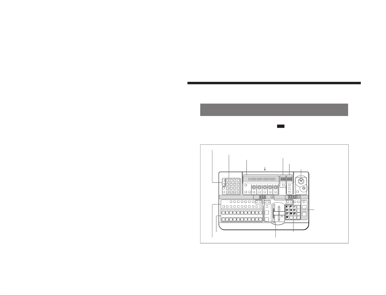
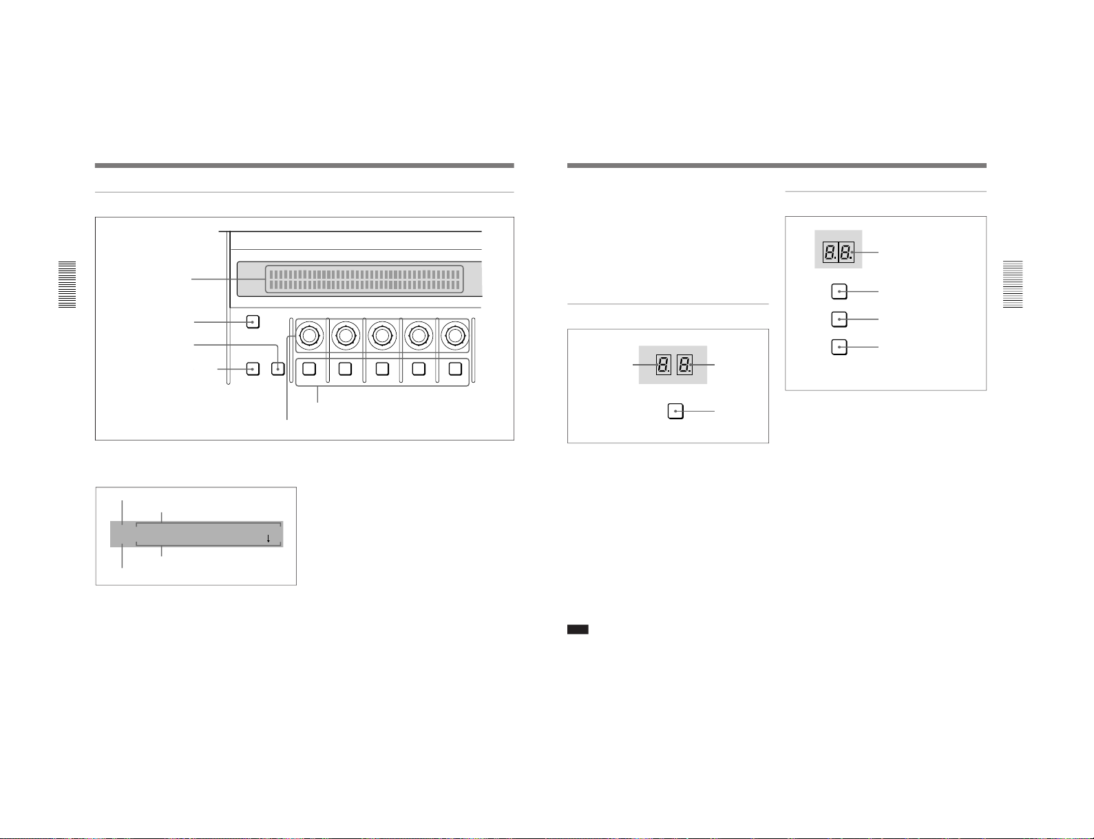
Control Panel
This section describes the control panel, which is
divided into several sections, as shown below. See the
page numbers shown in parenthesis for more details.
Note
If you make an error in operation, a warning sound
may occur. You can switch off this audible warning
(see page 6-10).
1 Delegation section
(see page 2-2)
LAST X
INS
RST
TITLE
12
EDITOR LUM LUM LUM
DSK EDGE
TRAIL
SHADOW
GPI CRK CRK BORDER BEVELD
EDGE
SET UP MASK MASK MASK SOFT
SHIFT CCR LIGHTING BORDERMATTES
LOCATION
LEARNEDIT
RECALL
HOLD
INPUT
INITIAL
PATTERN
ADJ
PAGE
F1 F2 F3 F4 F5
USER PGM
STATUS EDIT
SNAP SHOT
SET
PATTERN NUMBER
EFFECT
DSK
FTB
SET
TRANS RATE
789
456
123
0
DOWN UP
ENTER
FADE
TO
BLACK
P IN P
DSK
DEL
N/R REV DSK PVWDIRECT
RECALL
DIRECT
PATTERN
CCR TITLE 1
SOURCE
TITLE 2
SOURCE
DSK
FILL
SUPER BG FRGD 2 MEMORY FRAME FREEZ MIX EFFECT
BACKGROUND
BLACK MEMORY INT
VIDEO
TITLE
12345678
CUT
AUTO
TRANS
AUXILIARY
BLACK
MEMORY
INT
VIDEO
12345678
FOREGROUND
BLACK
MEMORY
INT
VIDEO
12345678
PATTERN/KEY PAD
2 Primary cross-point bus section
(see page 2-3)
3 Effect transition section
(see page 2-4)
4 Pattern/numeric keypad
(see page 2-5)
5 Fade-to-black
and DSK section
(see page 2-6)
6 EDITOR and GPI buttons
(see page 2-7)
7 Menu control section
(see page 2-7)
8 Effect control section
(see page 2-10)
9 User program section
(see page 2-11)
q; Snapshot section
(see page 2-11)
qa Location section
(see page 2-12)
qs 25-pin
connector
(see
page 2-12)
1-7
DFS-700/700P
Chapter 2 Location and Function of
Parts and Controls
2-2
Chapter 2 Location and Function of Parts and Controls
1 Delegation section
1 Delegation buttons
CCR TITLE 1
SOURCE
TITLE 2
SOURCE
DSK
FILL
SUPER BG FRGD 2 MEMORY FRAME FREEZ
BLACK MEMORY INT
VIDEO
12345678
AUXILIARY
2 AUXILIARY buttons
3 Frame memory buttons
1 Delegation buttons
Use these buttons to delegate the input signal
corresponding to the selected AUXILIARY button to
the corresponding function. Pressing one of these
buttons lights it, and the corresponding AUXILIARY
button also lights. Any other previously lit delegation
button goes off.
CCR (color corrector) button: Signal for color
correction
TITLE 1 SOURCE button: Title 1 source signal for
inserting characters and graphics using a title key
TITLE 2 SOURCE button: Title 2 source signal for
inserting characters and graphics using a title key
(only available when the optional BKDF-711 2nd
Channel DME Board is installed)
DSK (downstream keyer) FILL button: Fill signal
for the downstream keyer
SUPER BG (background) button: Background
image for 3D effects
FRGD (foreground) 2 button: One of the
foreground images for 3D effects
MEMORY button: Signal captured in frame
memory
2 AUXILIARY buttons
Select the input signal to be assigned to the function
selected with a delegation button.
Select from the following buttons.
BLACK button: Black burst signal generated by the
internal synchronizing signal generator in this unit
Buttons 1 to 8: Signals input to the VIDEO INPUT 1
to 8 connectors on the rear panel of the processor
unit. You can set the assignment of buttons to
input connectors in the setup menu.
MEMORY button: Signal recorded in frame
memory
INT (internal) VIDEO button: Signal generated by
the internal video signal generator
3 Frame memory buttons
FREEZ button: To capture the input signal selected
by the MEMORY button in the delegation buttons
(excluding the frame memory output signal) as a
freeze image in frame memory, press this button,
turning it on.
Press once more to end the freeze, turning it off.
FRAME button: Select whether to capture a frame
or a field with the FREEZ button. Press this
button, turning it on, to freeze a frame; when the
button is off a field is captured.
When capturing fields, you can select in the setup
menu whether to capture an odd or an even field.
Control Panel
Chapter 2 Location and Function of
Parts and Controls
Chapter 2 Location and Function of Parts and Controls
2-3
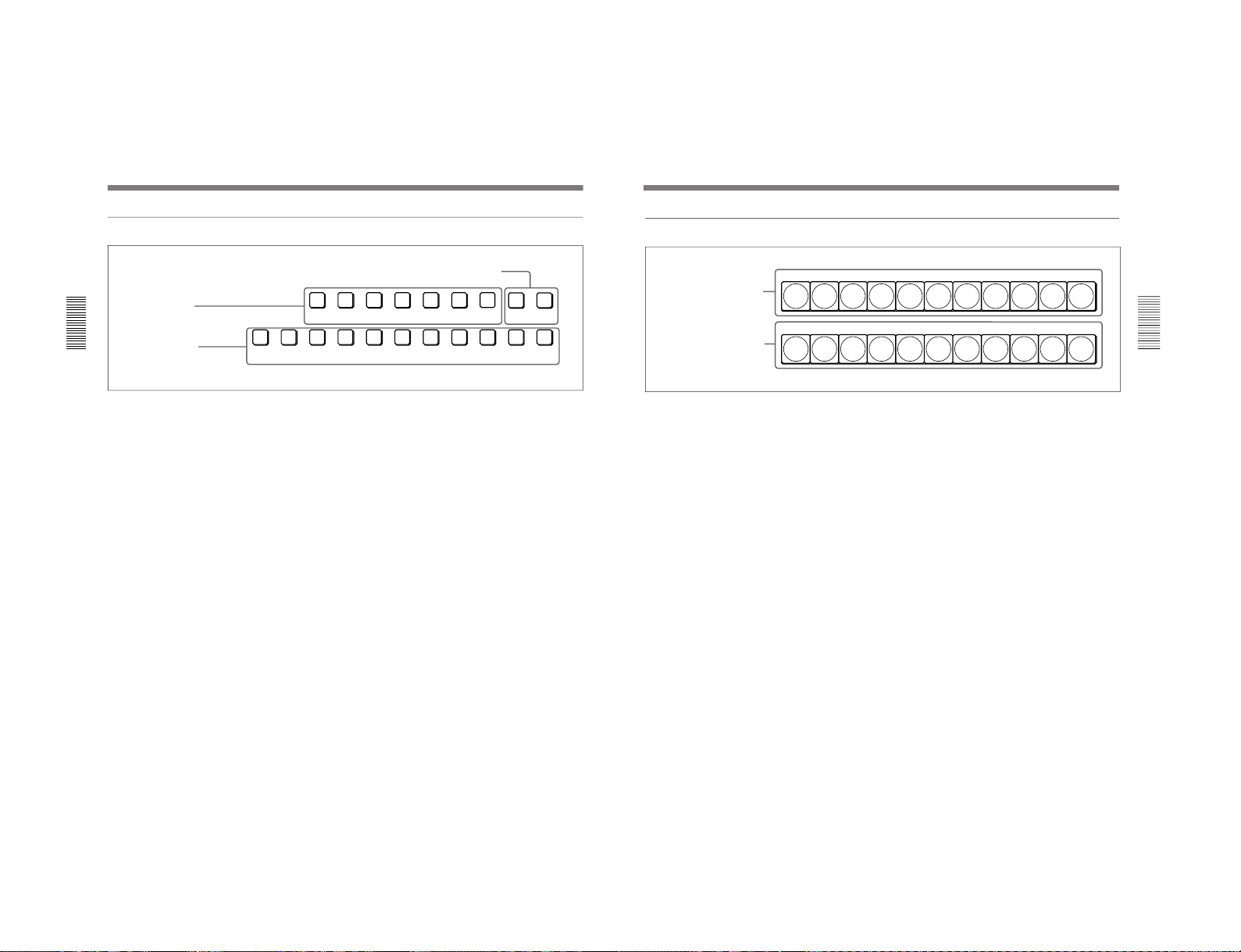
2 Primary cross-point bus section
BACKGROUND
BLACK
MEMORY
INT
VIDEO
12345678
FOREGROUND
BLACK
MEMORY
INT
VIDEO
12345678
2 FOREGROUND bus buttons
1 BACKGROUND bus buttons
1 BACKGROUND bus buttons
Select the image to form the background for an effect.
Select from the following buttons.
BLACK button: Select the black burst signal
generated by the internal synchronizing signal
generator in this unit.
Buttons 1 to 8: Signals input to the VIDEO INPUT 1
to 8 connectors on the rear panel of the processor
unit. Press a button, turning it on, to select the
corresponding signal.
You can set the assignment of buttons to input
connectors in the setup menu.
MEMORY button: Select the signal recorded in
frame memory.
INT (internal) VIDEO button: Select the internal
video signal selected by pressing the MATTES
button in the menu control section. If you hold
down this button and press the DOWN and UP
buttons in the pattern/numeric keypad, the
selected video signal pattern changes.
When the signal on the background bus is output from
the PGM OUT connector on the rear panel of the
processor unit, the button which has been pressed
lights red.
2 FOREGROUND bus buttons
Select the image to form the foreground for an effect
(or the “new” video in a transition).
The functions of the buttons are the same as in the
BACKGROUND bus buttons.
When the signal on the foreground bus is output from
the PGM OUT connector on the rear panel of the
processor unit, the button which has been pressed
lights red. If the signal is not output, the button pressed
lights amber.
1-8
DFS-700/700P
Chapter 2 Location and Function of
Parts and Controls
2-4
Chapter 2 Location and Function of Parts and Controls
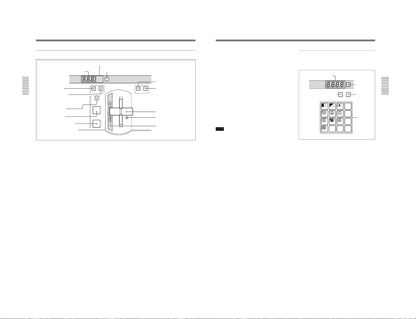
3 Effect transition section
EFFECT
DSK
FTB
SET
TRANS RATE
N/R REV
MIX EFFECT
TITLE
CUT
AUTO
TRANS
2 Display window mode indicators
3 SET button
4 MIX button
7 CUT button
1 TRANS RATE display window
5 EFFECT button
6 TITLE button
8 AUTO TRANS button
9 N/R button
q; REV button
qa Fader lever
qs Fader lever stiffness
adjusting screw
qd Transition indicator
1 TRANS (transition) RATE display window
This shows the transition time for effects, downstream
keys, and fade-to-black, in units of frames. While you
are entering a time, the dot at the lower right of each
numeral lights.
2 Display window mode indicators
These indicate the kind of transition time shown in the
TRANS RATE display window.
EFFECT: Transition time of an effect
DSK: Transition time of a downstream key
FTB: Transition time of a fade-to-black
3 SET button
To set the transition time for an effect, downstream
key, or fade-to-black, press this button, turning it on.
While it is lit, each time you press, the display window
mode indicators change. To set the transition time
corresponding to the display of the display window
mode indicators, enter the value using the pattern/
numeric keypad.
4 MIX button
To carry out the next transition without applying an
effect pattern, but as a mix, press this button, turning it
on.
5 EFFECT button
To carry out the next transition with an effect pattern
applied, press this button, turning it on.
6 TITLE button
To carry out an effect or a mix in title mode, press this
button, turning it on. The title keying is carried out,
inserting the characters and graphics with the effect
pattern and transition settings applied.
7 CUT button
Press this button to carry out an instantaneous
transition.
8 AUTO TRANS (automatic transition) button
Press this button to carry out an effect automatically.
When you press this button, the effect is carried out
automatically, with the transition time which has been
set. During the transition this button is lit. Pressing this
button during the transition pauses it. Press the button
once more to resume the transition.
If you set the fader lever to an intermediate position
and press this button, the transition pauses at the
position corresponding to the fader lever position.
Control Panel
Chapter 2 Location and Function of
Parts and Controls
Chapter 2 Location and Function of Parts and Controls
2-5
9 N/R (normal/reverse) button
To carry out an effect in normal/reverse (i.e.
alternating) mode, press this button, turning it on. It
lights automatically for animation effects and title
keys.
q; REV (reverse) button
To carry out an effect in the reverse direction, press
this button, turning it on.
For an effect for which normal/reverse (alternating)
operation is possible, once the effect is carried out, the
direction is automatically reversed. After an effect is
carried out in the normal (i.e. forward) direction, this
button lights. After an effect is carried out in the
reverse direction, this button goes off.
qa Fader lever
Move this to carry out an effect transition manually.
Note
After powering the system on, move the fader lever to
the end of its travel once in each direction. This
ensures that the fader lever will function correctly.
qs Fader lever stiffness adjusting screw
Turn this screw with a miniature Phillips screwdriver
to adjust the fader lever stiffness. Turn clockwise to
make the fader lever harder to move, and
counterclockwise to make it easier to move.
qd Transition indicator
This indicator consisting of 20 LEDs shows the
progress of an effect transition.
LAST X
INS
RST
SET
PATTERN NUMBER
789
456
123
0
DOWN UP
ENTER
P IN P
DEL
DIRECT
RECALL
DIRECT
PATTERN
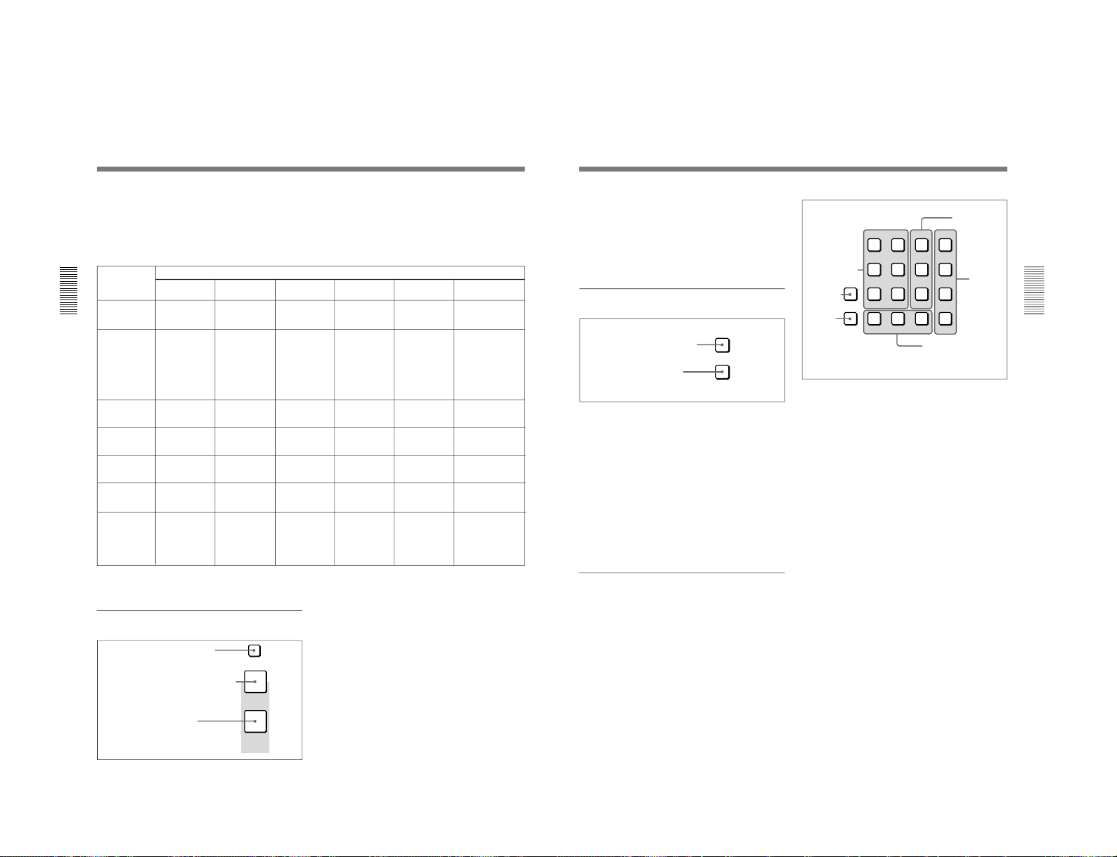
PATTERN/KEY PAD
4 Pattern/numeric keypad
This is used for effect pattern selection, transition time
setting, and other data entry.
1 PATTERN NUMBER display window
This shows an effect pattern number.
While you are entering a pattern number, the dot at the
lower right of each numeral lights.
2 SET button
Press this button, turning it on, to enter the pattern
number specification mode. In this mode, you can use
the PATTERN/KEY PAD buttons to specify an effect
pattern number.
Press this button once more, turning it off, to return to
the direct pattern selection mode.
3 DIRECT RECALL button
Press this button, turning it on, to enter the direct recall
mode. In this mode, pressing one of the PATTERN/
KEY PAD buttons 0 to 9 recalls the corresponding
snapshot 0 to 9.
4 DIRECT PATTERN button
Press this button, turning it on, to enter the direct
pattern selection mode. In this mode, you can use the
PATTERN/KEY PAD buttons (0 to 9 and P IN P/
RST) to directly select the assigned effect patterns.
When the system is powered on, and after exiting any
other operating mode, it automatically switches to
direct pattern selection mode.
1 PATTERN NUMBER
display window
3 DIRECT RECALL button
2 SET
button
4 DIRECT
PATTERN
button
5 PATTERN/
KEY PAD
buttons
1-9
DFS-700/700P
Chapter 2 Location and Function of
Parts and Controls
2-6
Chapter 2 Location and Function of Parts and Controls
5 PATTERN/KEY PAD buttons
These function as shown in the following table,
according to the selected mode.
Changing labels
You can change the labels on the buttons, using the
supplied labels.
For details of how to change the labels, see page A-63.
Button
Mode
DIRECT
PATTERN
PATTERN
TRANS USER PGM
SNAP SHOT
DIRECT RECALL
0 to 9 Select the
pattern shown
on the button.
a)
Set the pattern
number.
Set the
transition time.
–
Specify a
snapshot
number.
Recall one of
snapshots 0 to 9.
LAST X/INS –
–
– Add a key
frame.
Return to the
state before
recalling a
snapshot.
(Press LAST X
while holding
down the
ENTER button.)
Return to the state
before recalling a
snapshot. (Press
LAST X while
holding down the
ENTER button.)
DEL –
Delete the last
character
entered.
Delete the last
character
entered.
Delete a key
frame.
Delete the last
character
entered.
–
P IN P/RST
Select the
pattern shown
on the button.
a)
Reset the input
value.
Reset the input
value.
Initialize the
parameters.
Reset the input
value.
–
UP Increment the
pattern number.
Increment the
pattern number.
Increment the
transition time
by one frame.
Increment the
key frame
number.
Increment the
snapshot
number.
Increment the
snapshot number.
DOWN Decrement the
pattern number.
Decrement the
pattern number.
Decrement the
transition time
by one frame.
Decrement the
key frame
number.
Decrement the
snapshot
number.
Decrement the
snapshot number.
ENTER – Confirm the
input value.
Confirm the
input value.
Change the key
frame.
Confirm the
input value.
–: Not used
a) For the pattern allocation, see pages 3-18 to 3-20.
5 Fade-to-black and DSK section
FADE
TO
BLACK
DSK
DSK PVW
1 DSK PVW button
2 FADE TO BLACK button
1 DSK PVW (downstream keyer preview) button
When this button is pressed, turning it on, the program
output video is output from the preview output
connectors with the downstream key inserted.
2 FADE TO BLACK button
Press this button, turning it on, to change the entire
program output video to a preset color (factory default:
black). To set the color, press the MATTES button in
the menu control section, and display the setting menu
in the effect control section ((F1) SELECT-FTB).
By pressing the SET button in the effect transition
section, you can set the fade-to-black transition time.
Control Panel
Functions of the PATTERN/KEY PAD buttons
Return to the state
before recalling a
snapshot. (Press
LAST X while
holding down the
ENTER button.)
3 DSK button
Chapter 2 Location and Function of
Parts and Controls
Chapter 2 Location and Function of Parts and Controls
2-7
3 DSK (downstream keyer) button
Press this button, turning it on, to insert the
downstream key set by the DSK section buttons in the
menu control section into the program output video.
By pressing the SET button in the effect transition
section, you can set the downstream key transition
time.
6 EDITOR and GPI buttons
1 EDITOR button
Press this button, turning it on, to accept control from
an external editor connected to the EDITOR connector
on the rear panel of the processor unit.
Press this button once again to turn it off; control is no
longer accepted from the external editor.
2 GPI button
Press this button, turning it on, to accept GPI signals
input to the GPI/T 1 and 2 connectors on the rear panel
of the processor unit.
Press this button once again to turn it off; GPI signals
are no longer accepted.
7 Menu control section
For various effect settings, you press a particular
button in the menu control section, to display a setting
menu in the effect control section. Some buttons toggle
on and off when pressed: in this case the
corresponding effect is disabled when the button is off.
Displaying the menu for a button already lit
Hold down the SHIFT button and press the button
again. This leaves the button lit (and the effect
enabled), while bringing up the menu in the effect
control section. For the LUM and CRK buttons in the
TITLE section, it is not necessary to hold down the
SHIFT button.
EDITOR
GPI
2 GPI button
1 EDITOR button
1 TITLE section
The title key function allows you to superimpose
characters or graphics by cutting out part of the
foreground video with a key source signal, and
applying the effect to the background video.
There are two ways of using the key source signal: as a
luminance key depending only on image intensity, or
as a chroma key, based on a particular color.
Using the buttons in columns 1 and 2 of the TITLE
section, you can insert two title keys (TITLE 2
requires the optional BKDF-711 board to be installed).
To insert a title key, press the TITLE button in the
effect transition section.
The TITLE 1 and TITLE 2 buttons include the
following.
CRK (chroma key) button: Press this to use a
chroma key to cut out the image. When pressed,
this button lights, and portions of the foreground
image of the designated color are cut out as the
key source signal. When this button is lit, the
LUM button is off.
You can carry out chroma keying simply, using
the auto chroma key function.
LUM (luminance) button: Press this to use a
luminance key to cut out the image. When
pressed, this button lights, and portions of the
foreground image are cut out based on the
luminance level. When this button is lit, the CRK
button is off.
TITLE
12
LUM LUM LUM
DSK EDGE
TRAIL
SHADOW
CRK CRK BORDER BEVELD
EDGE
SET UP MASK MASK MASK SOFT
SHIFT CCR LIGHTING BORDERMATTES
2 DSK section
4 CCR, LIGHTING, and
MATTES buttons
1 TITLE section
5 SHIFT
button
6 SET UP
button
3 EDGE
section

1-10
DFS-700/700P
Chapter 2 Location and Function of
Parts and Controls
2-8
Chapter 2 Location and Function of Parts and Controls
MASK button: Press this button to mask off a part
of the key source signal. When you press this
button, it lights, and the system is now in mask
mode, and you can select a rectangular mask in
the effect control section. Normally, the area
outside the mask rectangle is the area which is
masked. To invert the mask, so that the area inside
the rectangle is masked, set INVERT (F5) to ON
in the effect control section.
Press the button once more to turn it off and end
mask mode.
2 DSK (downstream keyer) section
Using a downstream key, you can add characters or
graphics to an image to which an effect has already
been applied. Unlike a title key, you can add this to an
image with a foreground and background
superimposed. To insert a downstream key, press the
DSK button in the fade-to-black and DSK section.
LUM (luminance) button: Press this to display a
menu in the effect control section for adding a key
based on the luminance level of an input signal. In
the effect control section you can select the input
signal to the DSK KEY IN connector on the rear
panel or the input signal selected by the DSK
FILL button in the delegation section as the key
source signal.
BORDER button: Press this button to apply a border
to the characters and graphics inserted as a
downstream key. When you press this button, it
lights, and you can adjust the border settings in the
effect control section.
Press the button once more to turn it off, and
remove the border.
MASK button: Press this button to mask unwanted
parts of the characters and graphics inserted as a
downstream key. When you press this button, it
lights, and the system is now in mask mode, and
you can select a rectangular mask in the effect
control section. Normally, the area outside the
mask rectangle is the area which is masked. To
invert the mask, so that the area inside the
rectangle is masked, set INVERT (F5) to ON in
the effect control section.
Press the button once more to turn it off and end
mask mode.
3 EDGE section
This controls the edge effects applied to the boundary
between the foreground and background images.
TRAIL SHADOW button: Press this button to
apply a trail, drop border, or shadow effect. When
you press this button, it lights, and you can select
and adjust the effect in the effect control section.
•Trail: The foreground pattern leaves a trail of
afterimages.
•Drop border: This applies a border in the
background of the foreground image.
•Shadow: This applies a shadow behind the
foreground image.
Press the button once more to turn it off and
remove the edge effect.
BEVELD (beveled) EDGE button: Press this button
to apply a three-dimensional beveled effect to the
boundary between the foreground and background
images. When you press this button, it lights, and
you can adjust the beveled edge settings in the
effect control section.
Press the button once more to turn it off and
remove the beveled edge effect.
SOFT button: Press this button to soften the
boundary between the foreground and background
images. When you press this button, it lights, and
you can adjust the degree of softness in the effect
control section.
Press the button once more to turn it off and
remove the soft edge effect.
BORDER button: Press this button to apply a border
to the boundary between the foreground and
background images. When you press this button, it
lights, and you can adjust the border settings in the
effect control section.
Press the button once more to turn it off and
remove the border.
Adjusting the cropping: To adjust the cropping, use
the second page (CROP) of the adjustment menu
for beveled edge, soft edge, or border.
Control Panel
Chapter 2 Location and Function of
Parts and Controls
Chapter 2 Location and Function of Parts and Controls
2-9
4 CCR, LIGHTING, and MATTES buttons
CCR (color corrector) button: Press this button to
use the color corrector. When you press this
button, it lights, and you can adjust the color
corrector settings in the effect control section.
Press the button once more to turn it off and exit
the color corrector.
LIGHTING button: Press this button to apply
lighting effects to the foreground image. When
you press this button, it lights, and you can adjust
the lighting settings in the effect control section.
Press the button once more to turn it off and
remove the lighting effect.
MATTES button: By pressing this button, you can
carry out various matte adjustments, matte copies,
and internal video signal selections in the effect
control section.
5 SHIFT button
When a button in the menu control section is lit, but
the corresponding menu is not displayed in the effect
control section, hold down the SHIFT button and press
the lit button. This brings up the menu, without
interrupting the function selection, and leaving the
button lit.
This applies to the following buttons:
•MASK buttons in the TITLE section
•BORDER and MASK buttons in the DSK section
•TRAIL SHADOW, BEVELD EDGE, SOFT, and
BORDER buttons in the EDGE section
•CCR button and LIGHTING button
6 SET UP button
To access the setup menus for system and control
panel settings, press this button. The setup menu
appears in the effect control section.
1-11
DFS-700/700P
Chapter 2 Location and Function of
Parts and Controls
2-10
Chapter 2 Location and Function of Parts and Controls
8 Effect control section
INITIAL
PATTERN
ADJ
PAGE
F1 F2 F3 F4 F5
2 INITIAL button
3 PAGE button
5 Control knobs
6 F1 to F5 buttons
1 Menu display
4 PATTERN ADJ button
1 Menu display
This shows system and effect settings. Watch this
display while checking and adjusting the settings.
2 INITIAL button
This returns settings to their factory defaults.
•To return a selected setting to its factory default
Hold down the INITIAL button, and press the
corresponding F button (F1 to F5).
•To return all settings on the selected page to their
factory defaults
Hold down the INITIAL button, and press the PAGE
button.
•To return all settings on all pages of the currently
selected menu to their factory defaults (not valid
in setup menu or matte menu)
Hold down the INITIAL button, and press the
PATTERN ADJ button.
INIT SETUP--SNAP--USRPGM--KEYPAD EXEC
6/8 OFF OFF OFF OFF
Menu name or pattern number
Settings
Menu page
Setting values (ON/OFF or parameter values)
3 PAGE button
Press this button to move to the next page of a menu.
Pressing this button on the last page of a menu returns
to the first page.
Holding down the SHIFT button in the menu control
section and pressing this button moves to the previous
menu.
4 PATTERN ADJ (adjust) button
Press this button to adjust the settings for the pattern
number displayed in the PATTERN NUMBER display
window.
This displays the settings for the pattern in the effect
control section.
5 Control knobs
These correspond to the five settings shown in the
menu display. Turn the corresponding knob to adjust a
setting.
6 F1 to F5 buttons
These correspond to the five settings shown in the
menu display.
Press the corresponding button to select a setting, or
toggle it on and off.
Control Panel
Chapter 2 Location and Function of
Parts and Controls
Chapter 2 Location and Function of Parts and Controls
2-11
•Changing a setting value preceded by “+” (setup
menu operations)
Hold down the corresponding F button (F1 to F5),
and turn the control knob.
•Changing a setting value followed by “+” (user
program effect setting operations)
Hold down the corresponding F button (F1 to F5),
and enter the numeric value using the numeric
keypad.
9 User program section
1 STATUS display
When a user program effect is selected, this shows the
number of key frames comprising the effect.
(Maximum 8)
2 EDIT display
In the user program edit mode, this shows the key
frame number to which editing applies.
3 EDIT button
Press this button to edit a user program effect. When
you press this button, it lights, and the system enters
the user program edit mode.
Press the button once more to turn it off and exit the
user program edit mode.
Note
If you press the EDIT button when an effect other than
a user program effect is selected, this does not switch
to user program edit mode.
EDIT
USER
STATUS
EDIT
PGM
1 STATUS display
2 EDIT display
3 EDIT button
q; Snapshot section
1 SNAP SHOT number display
This shows a snapshot number (0 to 99). While you are
entering a number, the dot at the lower right of each
numeral lights.
2 LEARN button
Press this button to save the control panel settings as a
snapshot (learn function).
When you press this button, it lights, and the system
enters learn mode. Enter the snapshot number (0 to 99)
from the numeric keypad, and press the ENTER button
to save the control panel settings in the snapshot.
3 RECALL button
Press this button to recall settings saved as a snapshot.
When you press this button, it lights, and the system
enters recall mode. Enter the snapshot number (0 to
99) from the numeric keypad, and press the ENTER
button to recreate the control panel settings from the
snapshot on the control panel.
LEARN
RECALL
HOLD
INPUT
SNAP SHOT
1 SNAP SHOT number display
2 LEARN button
3 RECALL button
4 HOLD INPUT button
1-12
DFS-700/700P
Chapter 2 Location and Function of
Parts and Controls
2-12
Chapter 2 Location and Function of Parts and Controls
4 HOLD INPUT button
To hold the primary cross-point bus settings and the
auxiliary bus settings (signal selections) fixed when
recalling a snapshot, press this button. When you press
this button, it lights, and when you recall a snapshot,
the system is in the hold input mode. When you recall
a snapshot in this mode, all settings are recreated on
the control panel except those relating to the primary
cross-point bus and the auxiliary bus.
Press the button once more to turn it off and exit the
hold input mode.
qa Location section
1 LOCATION button
Press this button to use the joystick and Z-knob. When
you press this button, it lights, and enables the joystick
and Z-knob.
Press the button once more to disable the joystick and
Z-knob, and return the effect pattern to its default
position.
Holding down the INITIAL button while pressing this
button returns the setting to its default value.
2 Joystick
Use the joystick to position the effect pattern in the x-
and y-directions.
3 Z-knob
Turn the Z-knob to move an effect pattern in the depth
direction (the z-axis). With this you can change the
effective size of the pattern.
LOCATION
1 LOCATION button
2 Joystick
3 Z-knob
qs 25-pin connector (rear panel)
Use the supplied 25-pin control cable to connect this to
the PANEL connector on the processor unit.
Control Panel
Chapter 2 Location and Function of
Parts and Controls
Chapter 2 Location and Function of Parts and Controls
2-13
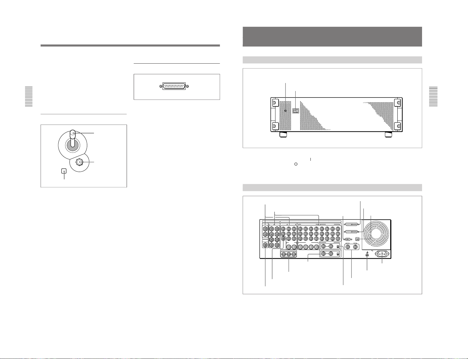
Processor Unit
Front Panel
Power indicator
Power switch
Power switch and indicator
This powers the unit on and off. Press the “
” side of
the switch to power on, and the “
” side to power off.
When the power is on, the power indicator lights
amber.
Rear Panel
1 PGM OUT connectors
1
3
1
2
1
2
2
1
3
4
5
6
7
8
21
Y
COMPOSITE
PGM OUT
CLEAN
OUT
OPTION
SDI INPUT PGM OUT
BLACK BURST OUT
VIDEO INPUT
COMPONENT
S VIDEO
COMPONENT/COMPOSITE
COMPONENT
DIGITAL I/O
ANALOG I/O
AC IN
2
R-Y
PVW
B-Y
65
Y/V
R-Y
B-Y
87
6/2 5/1
Y
R-Y
B-Y
8/4 7/3
2 1
REF.VIDEO IN
GPI/T
PANEL
TALLY
EDITOR
TERMINAL
DSK KEY IN
ON
OFF
OFF
75Ω
ON
75Ω
8
7 6 5
S VIDEO
(OPTION)
(OPTION)
2 1
2 VIDEO INPUT connectors
3 EDITOR
connector
4 PANEL connector
5 TALLY connector
6 TERMINAL connector
7 CLEAN OUT connector
8 PVW connector
9 BLACK BURST OUT 1 to 3
connectors
q; DSK KEY IN connectors
and 75Ω terminator
switch
qa REF. VIDEO IN connectors and 75Ω
terminator switch
qs GPI/T 1 and 2 connectors
qd U terminal
qf - AC IN connector

1-13
DFS-700/700P
Chapter 2 Location and Function of
Parts and Controls
2-14
Chapter 2 Location and Function of Parts and Controls
1 PGM OUT (program output) connectors
These output the final program output, that is, the
video to which effects have been applied. Connect to
VTR (recorder) and program monitor video input
connectors. The following four types of output are
provided, each with two channels (1 and 2).
SDI (BNC): Output serial digital signals (270 MHz).
COMPOSITE (BNC): Output composite video
signals.
COMPONENT (BNC): Output Betacam format
component video signals (Y, R–Y, B–Y).
S VIDEO (4-pin): Output S-video (Y/C separation)
signals.
You can use all four formats simultaneously. The same
signals are output from connectors 1 and 2.
2 VIDEO INPUT connectors
These input video camera and VTR (player) video
signals. The connectors are in four groups, as follows.
•SDI INPUT 1 to 4, (OPTION) 5 to 8 (BNC)
•COMPONENT 5/1, 6/2, 7/3, 8/4 (BNC)
•COMPONENT/COMPOSITE (OPTION) 5 to 8
(BNC)
•S VIDEO (OPTION) 5 to 8 (4-pin)
SDI INPUT 1 to 4, (OPTION) 5 to 8 (BNC-type)
Input serial digital signals (270 MHz).
Connectors 5 to 8 can only be used when the optional
BKDF-701 SDI and Component Input Board is
installed.
The input signals to these connectors must be
synchronized to this unit.
COMPONENT 5/1, 6/2, 7/3, 8/4 (BNC-type)
Input Betacam format component video signals.
Y: Input the luminance (Y) signal.
R–Y: Input the R–Y color difference signal.
B–Y: Input the B–Y color difference signal.
The input signals to these connectors must be
synchronized to this unit. Therefore, when inputing
from a VTR, the signal must come through a time base
corrector.
The 8/4 column of connectors can be changed to RGB
input connectors by a setup menu operation. In this
case, connect G (with sync), R, and B signals to Y, R–
Y, and B–Y respectively.
When the optional BKDF-702/702P Y/C and
Composite Input Board is installed, you can select in
the setup menu whether to use the 5/1, 6/2, 7/3, and
8/4 connectors for component inputs 5 to 8 or
component inputs 1 to 4.
COMPONENT/COMPOSITE (OPTION) 5 to 8
(BNC-type)
These connectors can be used by installing either of
the optional BKDF-701 and BKDF-702/702P boards.
When the BKDF-701 board is installed, connect
Betacam format component video signals. When the
BKDF-702/702P board is installed, connect composite
video signals. The signals can be input from a VTR
with no time base corrector. When using the BKDF-
701 to input signals from a VTR, they must come
through a time base corrector.
S VIDEO (OPTION) 5 to 8 (4-pin)
Input S-video (Y/C separation) signals. These
connectors can only be used when the optional BKDF-
702/702P board is installed. The signals can be input
from a VTR with no time base corrector.
3 EDITOR connector (9-pin)
Use this connector when controlling this unit with an
editor (PVE-500, BVE-2000 series, or other editing
control unit). Using an optional 9-pin remote control
cable, connect to the 9-pin control connector of the
editor.
4 PANEL connector (25-pin)
With the supplied 25-pin control cable, connect to the
25-pin connector of the control panel.
5 TALLY connector (25-pin)
Tally signals are output from this connector when the
signal input to a VIDEO INPUT connector is selected
on the control panel. Connect to the input signal
sources (video cameras etc.). The outputs are relay
contact signals, with a capacity of 200 mA / 30 V.
6 TERMINAL connector (USB type B)
This is a USB interface connector. Use it when
connecting to a computer for a software version
upgrade.
Connector
Input signal for
BKDF-701
Input signal for
BKDF-702/702P
Y/V Luminance (Y) signal
Composite signal
R–Y Color difference
signal (R–Y)
Not used
B–Y Color difference
signal (B–Y)
Not used
Processor Unit
Chapter 2 Location and Function of
Parts and Controls
Chapter 2 Location and Function of Parts and Controls
2-15
7 CLEAN OUT connector (BNC-type)
Outputs serial digital signals (270 MHz). Using the
setup menu, you can select the output from the
following three signals.
CLEAN OUT: The program output signal, without
the downstream key inserted.
PVW OUT: The signal output is the same as the
program output after completion of the effect
transition. The title area can also be shown.
KEY OUT: This outputs a key signal corresponding
to the shape of a selected effect. Use it as the key
source input to another device.
8 PVW (preview) connector (BNC-type)
This is an analog composite preview output. The signal
output is the same as the program output after
completion of the effect transition. It is not possible to
include the title area.
9 BLACK BURST OUT 1 to 3 connectors (BNC-
type)
These output the black burst signals generated by the
synchronizing signal generator internal to this unit.
When an external synchronizing signal is input to the
REF. VIDEO IN connectors, the black burst signal
output is locked to the external synchronizing signal.
Use the output from these connectors as a reference
synchronizing signal when synchronizing input signal
sources (character generators, etc.), or when
synchronizing this unit with a VTR or editor to
improve the precision of editing.
q; DSK (downstream keyer) KEY IN connectors
(BNC-type) and 75 Ω terminator switch
Input the key source signal for a downstream key,
from a character generator or other device.
When the 75 Ω terminator switch is in the OFF
position, the connectors provide a loop-through
connection; with the key signal input to one connector,
the other provides the same key source signal to
another device. By connecting to an analog component
Y connector on this unit, you can use it as a title key
source.
When not using the loop-through output, the 75 Ω
terminatior switch must be in the ON position.
qa REF. (reference) VIDEO IN connectors (BNC-
type) and 75Ω terminator switch
When using this unit synchronized to an external
signal, input the external reference signal (black burst).
When the 75Ω terminatior switch is in the OFF
position, the connectors provide a loop-through
connection; with the reference signal input to one
connector, the other provides the same reference signal
for another device. When not using the loop-through
output, the 75Ω terminatior switch must be in the ON
position.
qs GPI/T (GPI/trigger) 1 and 2 connectors (BNC-
type)
Input external trigger signals. These are used when
controlling editing with GPI signals or an editor (BVE-
600).
qd U (ground) terminal
Connect this to ground as required.
qf - AC IN connector
With the supplied power cord, connect to the AC
supply.
1-14
DFS-700/700P
Chapter 3 Basic Operation
3-1
Chapter
3
Basic Operation
DME Switcher Introduction
This section selects two of the many effects provided by the DFS-700/
700P as examples, and describes the basic flow of operations to use them.
It also describes the demonstration function, which automatically executes
one hundred sample effects.
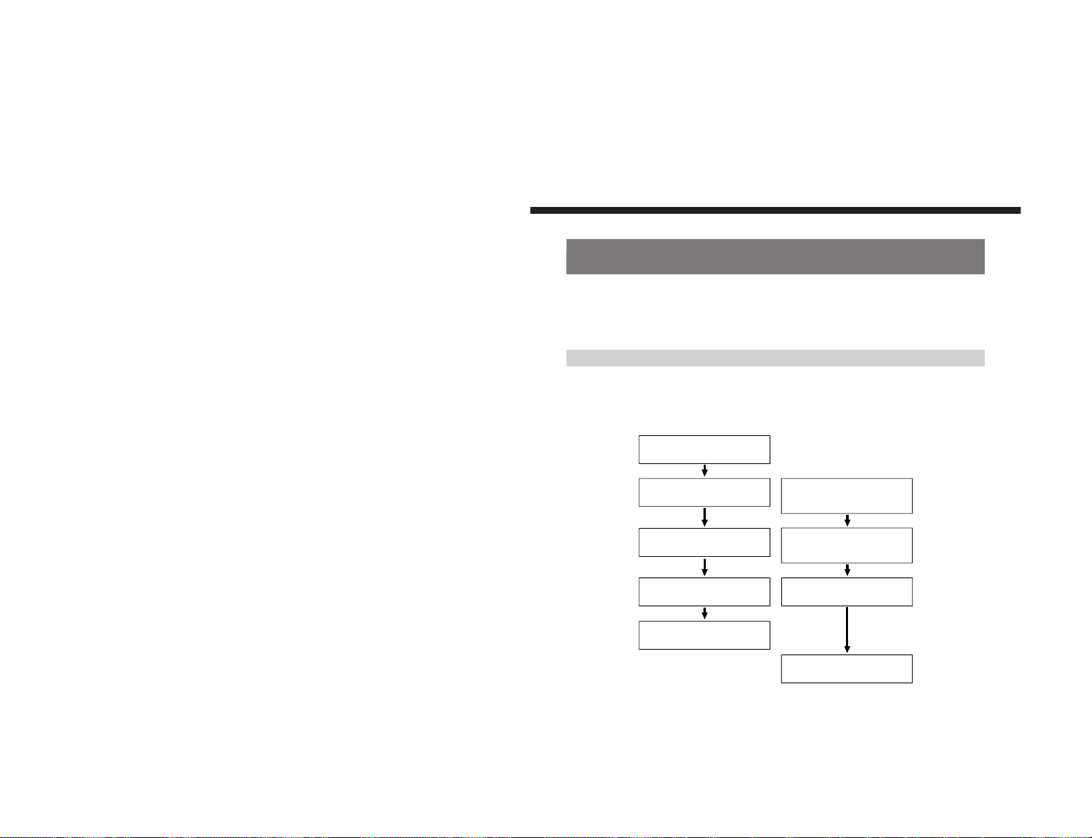
Sequence of Operations
The flow charts below show the general sequence of operations when
using a DME switcher.
Basic operations (to be
always carried out)
Advanced operations (to be
carried out as required)
Select the background image
(see page 3-13)
Select the foreground image
(see page 3-13)
Inserting characters and graphics (1)
• Luminance key
(see page 3-33)
• Chroma key
(see page 3-36)
Select the effect
(see pages 3-23 and 24)
• Modifying the boundary
(see page 3-26)
• Changing the position and size
(see page
3-29)
• Modifying the pattern
(see page 3-31)
Set up the transition
(see page 3-51)
Reversing the direction of the effect
(see page 3-52)
Execute the effect
(see page 3-54)
Inserting characters and graphics (2)
• Downstream key
(see page 3-45)
1-15
DFS-700/700P
Chapter 3 Basic Operation
3-2
Chapter 3 Basic Operation
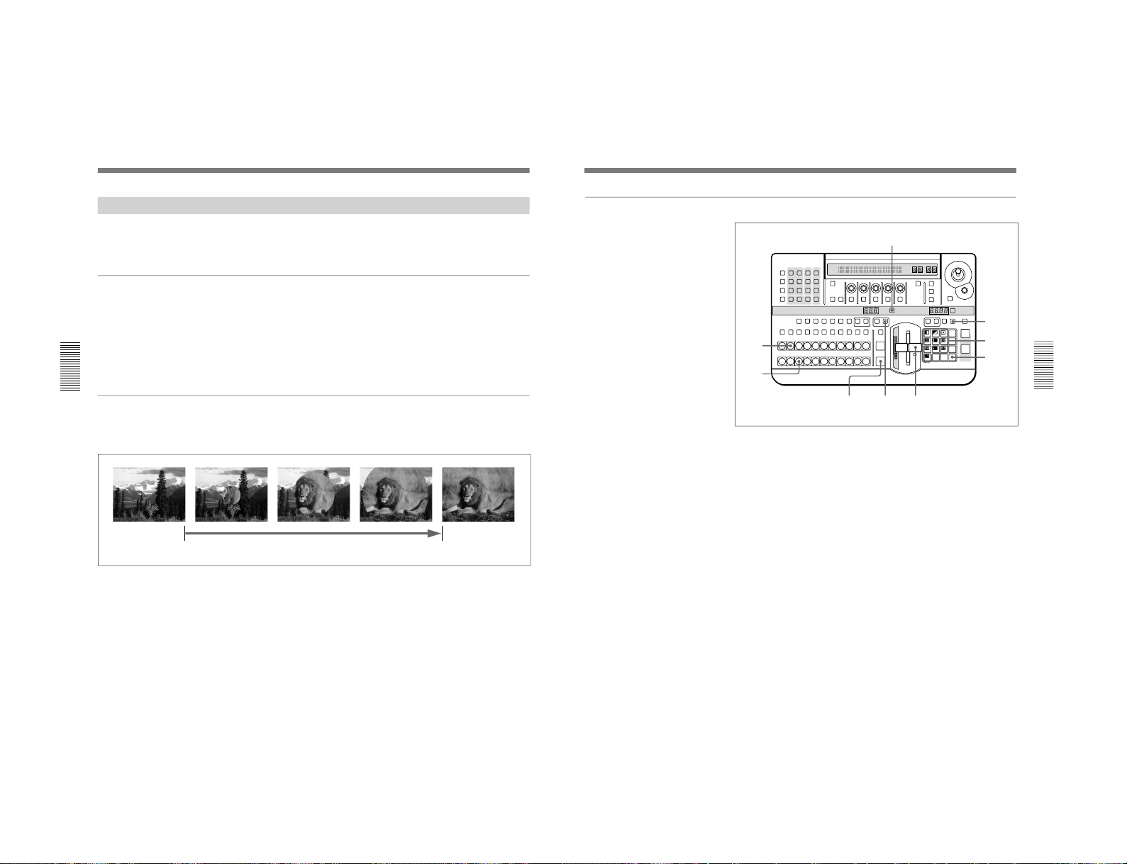
Example Operation (1): Wipe
In this example we’ll use the AUTO TRANS button, to make a wipe, with
the new image appearing from the center of the screen.
Setting items
As an example, we’ll set the control panel as follows.
Background image (the image output before the transition): video
signal connected to the VIDEO INPUT 1 connector
Foreground image (the image output after the transition): video
signal connected to the VIDEO INPUT 2 connector
Effect: wipe (pattern number 24)
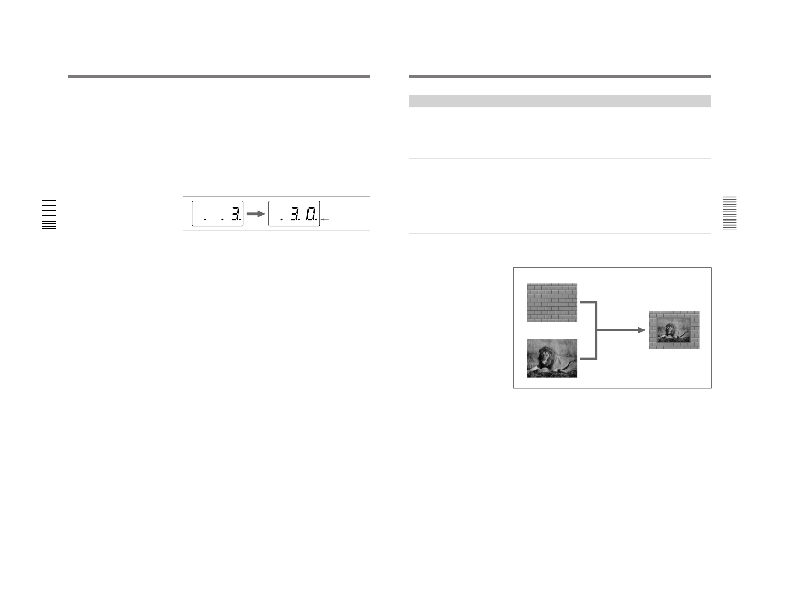
Transition time: 30 frames
Program output
Executing the above effect produces the following changes in the output
on a program monitor connected to the PGM OUT connector of the
processor unit.
DME Switcher Introduction
Start of effect
Transition time
End of effect
Chapter 3 Basic Operation
Chapter 3 Basic Operation
3-3
<Preparation>
<Image selection>
Procedure
1
Pull the fader lever toward you as far as it will go.
2
Press BACKGROUND Bus button 1.
The pressed button lights red, and the video signal connected to the
VIDEO INPUT 1 connector is selected as the background image. The
selected background image appears on the program monitor.
3
Press FOREGROUND Bus button 2.
The pressed button lights amber, and the video signal connected to the
VIDEO INPUT 2 connector is selected as the foreground image.
To check the selected image on the program monitor, move the fader
lever to the opposite end. After checking, return the lever to the
position closest to you.
If a preview monitor is connected, the selected foreground image
appears in the preview monitor.
4
Press the DIRECT PATTERN button, turning it on.
(If it is already lit, omit this step.)
The unit is now in direct pattern selection mode. In this mode, you can
select the eleven patterns assigned to buttons in the pattern/numeric
keypad using the corresponding button.
LAST X
INS
RST
TITLE
12
EDITOR LUM LUM LUM
DSK EDGE
TRAIL
SHADOW
GPI CRK CRK BORDER BEVELD
EDGE
SET UP MASK MASK MASK SOFT
SHIFT CCR LIGHTING BORDERMATTES
LOCATION
LEARNEDIT
RECALL
HOLD
INPUT
INITIAL
PATTERN
ADJ
PAGE
F1 F2 F3 F4 F5
USER PGM
STATUS EDIT
SNAP SHOT
SET
PATTERN NUMBER
EFFECT
DSK
FTB
SET
TRANS RATE
789
456
123
0
DOWN UP
ENTER
FADE
TO
BLACK
P IN P
DSK
DEL
N/R REV DSK PVWDIRECT
RECALL
DIRECT
PATTERN
CCR TITLE 1
SOURCE
TITLE 2
SOURCE
DSK
FILL
SUPER BGFRGD 2 MEMORY FRAME FREEZ MIX EFFECT
BACKGROUND
BLACK MEMORY INT
VIDEO
TITLE
12345678
CUT
AUTO
TRANS
AUXILIARY
BLACK
MEMORY
INT
VIDEO
12345678
FOREGROUND
BLACK
MEMORY
INT
VIDEO
12345678
PATTERN/KEY PAD
8
910
3
2
1
6
5,7
4
(Continued)
<Effect selection>
1-16
DFS-700/700P
Chapter 3 Basic Operation
3-4
Chapter 3 Basic Operation
5
Press button 9 in the pattern/numeric keypad.
The button lights, and this selects the wipe assigned to this button
(pattern number 24). The PATTERN NUMBER display window
shows “0024”.
6
Press the SET button once or twice, so that the EFFECT display
window mode indicator lights.
(If it is already lit, omit this step.)
7
In the pattern/numeric keypad, press buttons 3 and 0 in that order.
The TRANS RATE display window shows “.3.0.”.
8
Press the ENTER button.
The dots to the lower right of the digits disappear, and the value
entered in step 7 is set as the transition time.
9
Press the EFFECT button, turning it on.
(If it is already lit, omit this step.)
10
Press the AUTO TRANS button.
The wipe is carried out over 30 frames, switching from the background
image to the foreground image.
When the transition completes, BACKGROUND bus button 2 is lit
red, and FOREGROUND bus button 1 is lit amber. This indicates that
as a result of the transition, the video signal connected to the VIDEO
INPUT 2 connector is automatically selected as the background image,
and the video signal connected to the VIDEO INPUT 1 connector as
the foreground image.
DME Switcher Introduction
<Transition time setting>
Dots appear to
the lower right of
the digits
Chapter 3 Basic Operation
Chapter 3 Basic Operation
3-5
Example Operation (2): Picture-in-Picture
Using the fader lever, we’ll insert the foreground image within the
background image.
We’ll apply a border around the edge of the foreground image.
Setting items
As an example, we’ll set the control panel as follows.
Background image: internal video signal (color background )
Foreground image: video signal connected to the VIDEO INPUT 1
connector
Effect: picture-in-picture (pattern number 1100)
Border: ON
Program output
Executing the above effect produces the following changes in the output
on a program monitor.
Background image
Foreground image
Effect execution
Program output
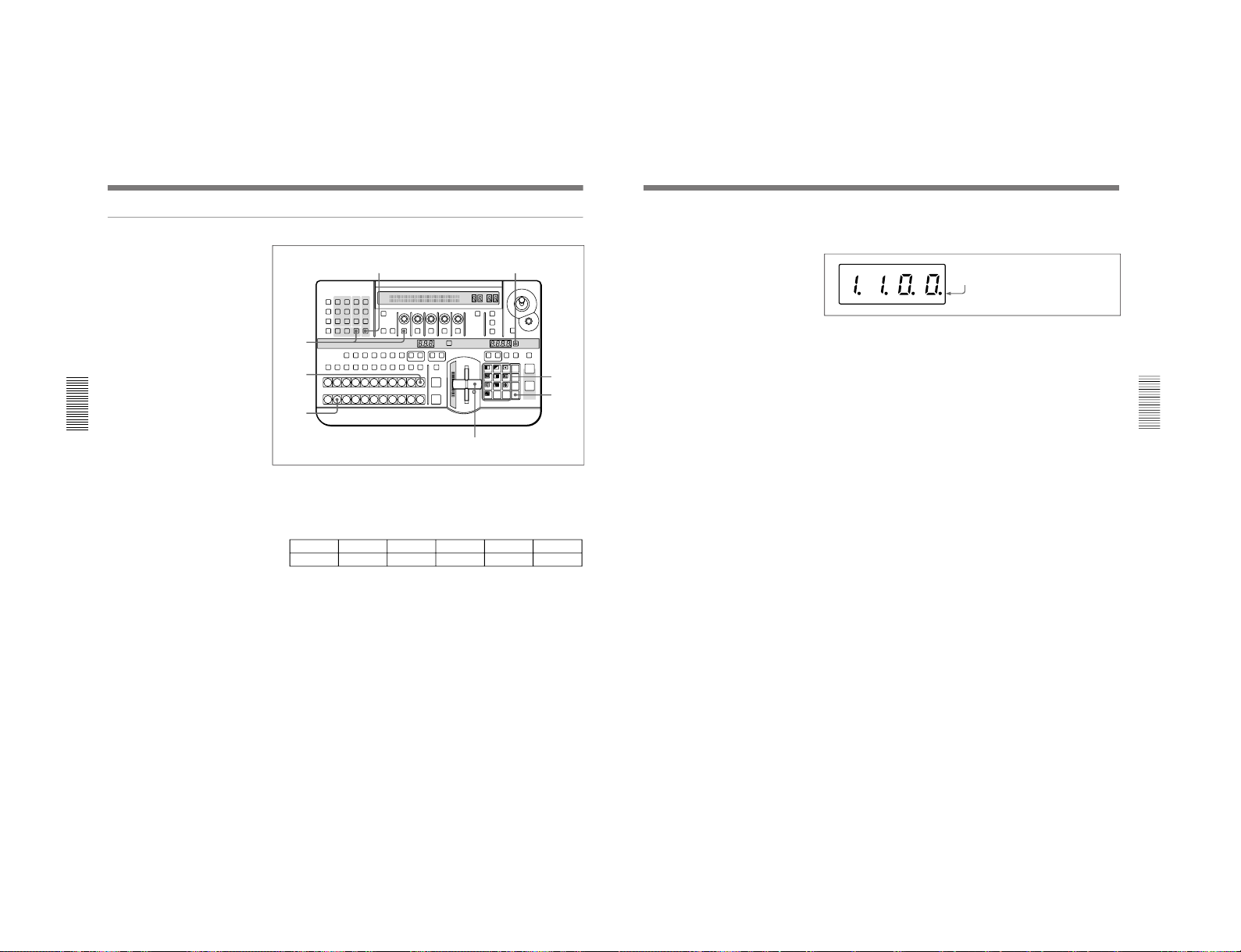
1-17
DFS-700/700P
Chapter 3 Basic Operation
3-6
Chapter 3 Basic Operation
Procedure
1
Pull the fader lever toward you as far as it will go.
2
Press the MATTES button in the menu control section, and display
page 1 of the MATTE menu, then with the F1(SELECT) button select
“INT V”.
MATTE
1/2
SELECT
INT V
Lum
0-100
Sat
0-100
Hue
0-99
CH2BRD
BRDMAT
PA GE F1 F2 F3 F4 F5
You can change the color of matte color and embossing pattern. For details,
see the section “Adjusting Color Mattes” (page 3-57).
3
Press the BACKGROUND bus INT VIDEO button.
The pressed button lights red, and a color matte is selected as the
background image.
4
Press the FOREGROUND bus button 1.
The pressed button lights amber, and the video signal connected to the
VIDEO INPUT 1 connector is selected as the foreground image.
5
Press the SET button to the right of the PATTERN NUMBER display
window, turning it on.
(If it is already lit, omit this step.)
LAST X
INS
RST
TITLE
12
EDITOR LUM LUM LUM
DSK EDGE
TRAIL
SHADOW
GPI CRK CRK BORDER BEVELD
EDGE
SET UP MASK MASK MASK SOFT
SHIFT CCR LIGHTING BORDERMATTES
LOCATION
LEARNEDIT
RECALL
HOLD
INPUT
INITIAL
PATTERN
ADJ
PAGE
F1 F2 F3 F4 F5
USER PGM
STATUS EDIT
SNAP SHOT
SET
PATTERN NUMBER
EFFECT
DSK
FTB
SET
TRANS RATE
789
456
123
0
DOWN UP
ENTER
FADE
TO
BLACK
P IN P
DSK
DEL
N/R REV DSK PVWDIRECT
RECALL
DIRECT
PATTERN
CCR TITLE 1
SOURCE
TITLE 2
SOURCE
DSK
FILL
SUPER BGFRGD 2 MEMORY FRAME FREEZ MIX EFFECT
BACKGROUND
BLACK MEMORY INT
VIDEO
TITLE
12345678
CUT
AUTO
TRANS
AUXILIARY
BLACK
MEMORY
INT
VIDEO
12345678
FOREGROUND
BLACK
MEMORY
INT
VIDEO
12345678
PATTERN/KEY PAD
7
4
3
1,9
8
6
2
5
DME Switcher Introduction
<Preparation>
<Image selection>
<Effect selection>
Chapter 3 Basic Operation
Chapter 3 Basic Operation
3-7
<Effect execution>
6
In the numeric keypad, press buttons 1, 1, 0, 0, in that order.
The TRANS RATE display window shows “1.1.0.0.”.
7
Press the ENTER button.
The dots to the lower right of the digits disappear, and picture-in-
picture, or pattern number 1100, is selected.
8
In the menu control section, press the BORDER button.
The button lights, enabling the border.
You can change the color and width of the border. For details, see the section
“Modifying the Boundary” (page 3-26).
9
Move the fader lever to the opposite end.
Both the BACKGROUND bus INT VIDEO button and the
FOREGROUND bus button 1 light red.
As you move the lever, the picture-in-picture effect takes place, and a
foreground image with a border is inserted into the background image.
Dots appear to the lower right of the digits.
<Border settings>
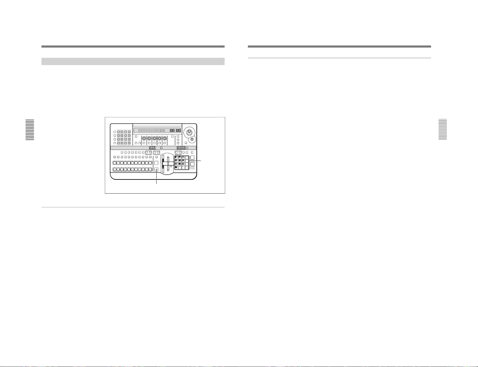
1-18
DFS-700/700P
Chapter 3 Basic Operation
3-8
Chapter 3 Basic Operation
Demonstration
The DFS-700/700P is equipped with a demonstration function, which
automatically plays back one hundred effects stored in ROM in the
processor unit.
The effects (which by factory default are snapshots 0 to 99) have been
chosen to demonstrate the features of the DFS-700/700P as effectively as
possible.
For maximum effect, the demonstration function uses the signals
connected to VIDEO INPUT connectors 1 and 2, and the internal video
signal.
Buttons used for the demonstration
To start the demonstration
In the pattern/numeric keypad, hold down buttons 1 and 9, and press the
AUTO TRANS button.
The one hundred effects stored in ROM are played back continuously, and
repeated until you press the AUTO TRANS button once more. During the
demonstration, the buttons on the pattern/numeric keypad light in turn in
the clockwise direction.
During the demonstration, the control panel does not accept any operations
other than pressing the AUTO TRANS button.
Demonstration with user-registered snapshots
It is also possible to have a demonstration with user-registered snapshots.
In this case, hold down buttons 3 and 7 in the pattern/numeric keypad, and
press the AUTO TRANS button. During the demonstration, the buttons on
the pattern/numeric keypad light in turn in the counterclockwise direction.
LAST X
INS
RST
TITLE
12
EDITOR LUM LUM LUM
DSK EDGE
TRAIL
SHADOW
GPI CRK CRK BORDER BEVELD
EDGE
SET UP MASK MASK MASK SOFT
SHIFT CCR LIGHTING BORDERMATTES
LOCATION
LEARNEDIT
RECALL
HOLD
INPUT
INITIAL
PATTERN
ADJ
PAGE
F1 F2 F3 F4 F5
USER PGM
STATUS EDIT
SNAP SHOT
SET
PATTERN NUMBER
EFFECT
DSK
FTB
SET
TRANS RATE
789
456
123
0
DOWN UP
ENTER
FADE
TO
BLACK
P IN P
DSK
DEL
N/R REV DSK PVWDIRECT
RECALL
DIRECT
PATTERN
CCR TITLE 1
SOURCE
TITLE 2
SOURCE
DSK
FILL
SUPER BGFRGD 2 MEMORY FRAME FREEZ MIX EFFECT
BACKGROUND
BLACK MEMORY INT
VIDEO
TITLE
12345678
CUT
AUTO
TRANS
AUXILIARY
BLACK
MEMORY
INT
VIDEO
12345678
FOREGROUND
BLACK
MEMORY
INT
VIDEO
12345678
PATTERN/KEY PAD
Pattern/numeric
keypad
AUTO TRANS button
DME Switcher Introduction
Chapter 3 Basic Operation
Chapter 3 Basic Operation
3-9
To end the demonstration
Press the AUTO TRANS button once more.
The demonstration ends, and the control panel settings are those of the last
effect in the demonstration.
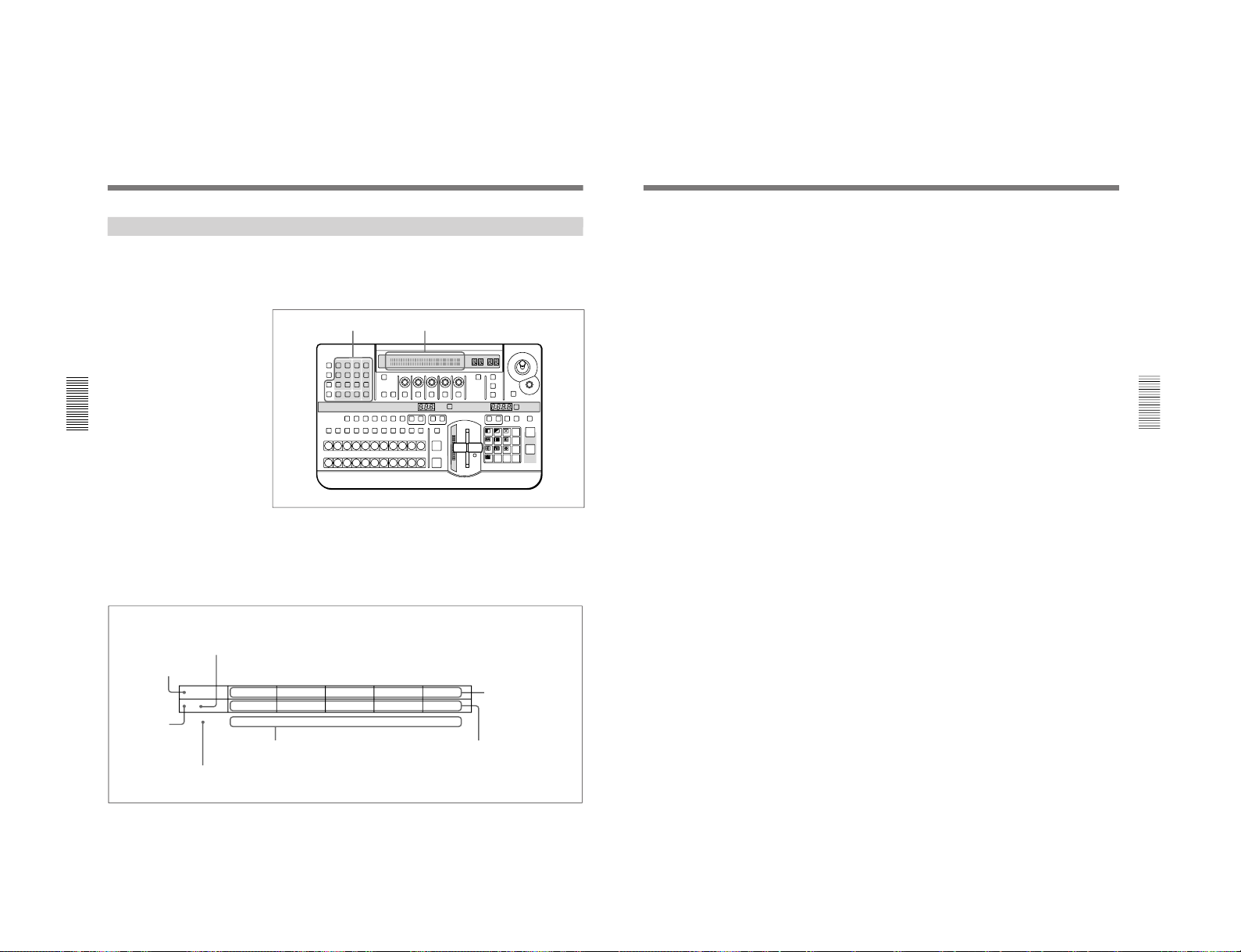
1-19
DFS-700/700P
Chapter 3 Basic Operation
3-10
Chapter 3 Basic Operation
Using the Menus
This unit incorporates menus for various effect settings and internal color
matte settings, and also a setup menu for system settings.
This section describes the basic menu operation.
Accessing a menu
Press one of the buttons in the menu control section.
For example, to recall the menu for internal color matte settings, press the
MATTES button in the menu control section. The MATTE menu appears
in the menu display in the effect control section.
In this manual, menus are shown in a tabular format. The following
example shows the MATTE menu.
LAST X
INS
RST
TITLE
12
EDITOR LUM LUM LUM
DSK EDGE
TRAIL
SHADOW
GPI CRK CRK BORDER BEVELD
EDGE
SET UP MASK MASK MASK SOFT
SHIFT CCR LIGHTING BORDERMATTES
LOCATION
LEARNEDIT
RECALL
HOLD
INPUT
INITIAL
PATTERN
ADJ
PAGE
F1 F2 F3 F4 F5
USER PGM
STATUS EDIT
SNAP SHOT
SET
PATTERN NUMBER
EFFECT
DSK
FTB
SET
TRANS RATE
789
456
123
0
DOWN UP
ENTER
FADE
TO
BLACK
P IN P
DSK
DEL
N/R REV DSK PVWDIRECT
RECALL
DIRECT
PATTERN
CCR TITLE 1
SOURCE
TITLE 2
SOURCE
DSK
FILL
SUPER BGFRGD 2 MEMORY FRAME FREEZ MIX EFFECT
BACKGROUND
BLACK MEMORY INT
VIDEO
TITLE
12345678
CUT
AUTO
TRANS
AUXILIARY
BLACK
MEMORY
INT
VIDEO
12345678
FOREGROUND
BLACK
MEMORY
INT
VIDEO
12345678
PATTERN/KEY PAD
Menu control section
Menu page number
“1/2” means that this is the
first of two pages.
Menu name
Refers to the PAGE button.
Refers to buttons and
knobs F1 to F5.
Setting items
(parameters)
Values for the settings
“0-100” indicates a numerical range.
Menu display
MATTE
P 1/2
SELECT
INT V
Lum
0-100
Sat
0-100
Hue
0-99
CH2BRD
BRDMAT
PA GE F1 F2 F3 F4 F5
A “P” appears
here when preread
editing is on.
DME Switcher Introduction
Chapter 3 Basic Operation
Chapter 3 Basic Operation
3-11
Changing settings
•For settings with values shown in letters, press the corresponding one of
buttons F1 to F5.
In the text, this is shown as “the F1(SELECT) button,” with the setting
name after the button name F1 to F5.
•To change a setting with a numerical value, turn the corresponding one of
control knobs F1 to F5.
In the text, this is shown as “the F2(Lum) knob,” with the setting name
after the knob name F1 to F5.
•In the setup menu, when an item has a plus sign in front, hold down the F
button (F4 or F5) and turn the corresponding knob.
For example, in page 3/8 of the setup menu, to change the setting for F4
[+H-pos], hold down the F4 button and turn the F4 knob.
To change the menu page
Press the PAGE button.
Buttons of the menu control section which light when pressed
When you press one of these buttons, it lights, and the settings in the menu
recalled by the button are reflected in the monitor display. To avoid this,
for example just to check the settings in a menu, hold down the SHIFT
button while pressing the menu button.
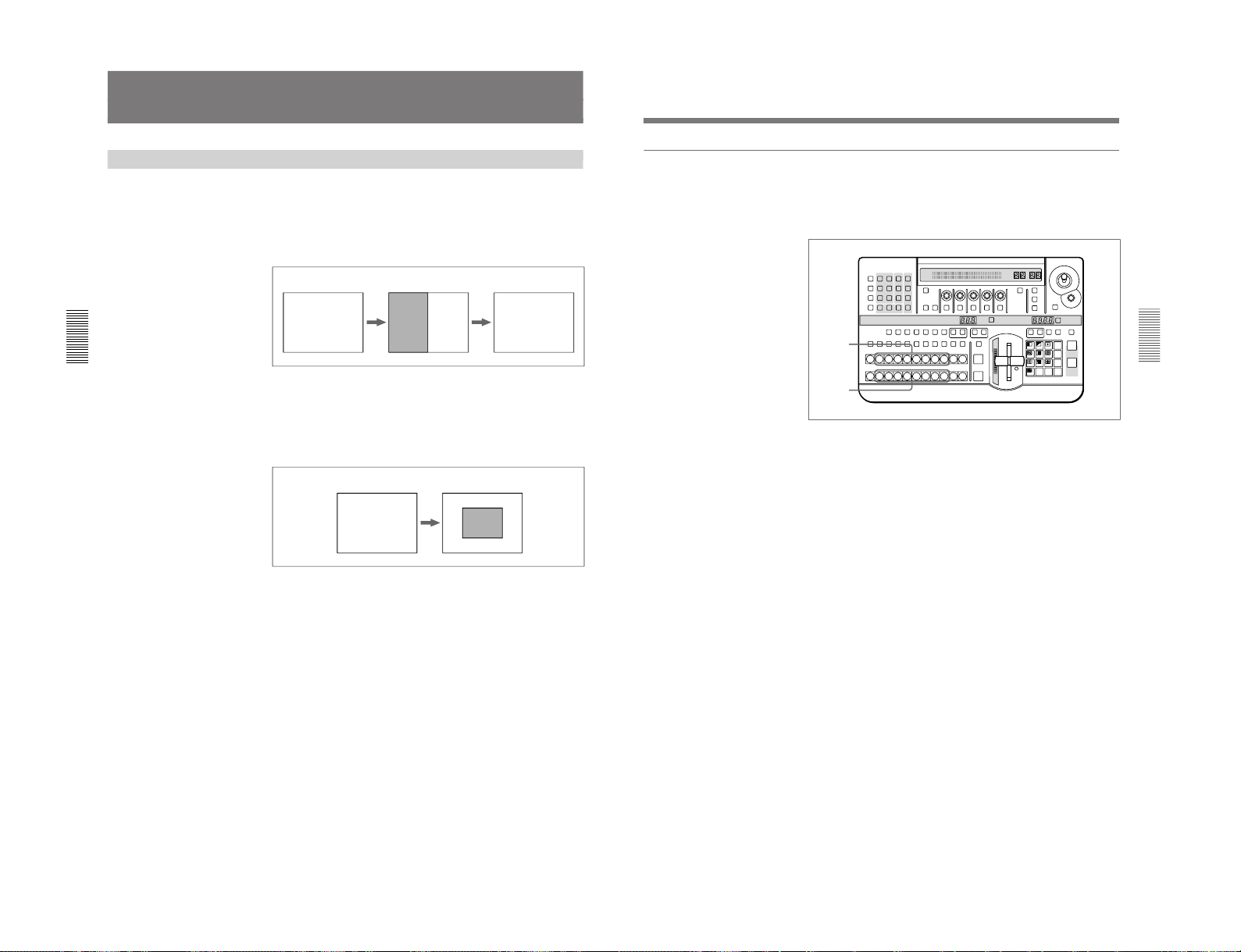
1-20
DFS-700/700P
Chapter 3 Basic Operation
3-12
Chapter 3 Basic Operation
Selecting Images
BF FB
B: background image F: foreground image
B
F
B
B: background image F: foreground image
Background Image and Foreground Image
Background and foreground in a transition effect
In a transition from one image to another, the old image is referred to as
the “background image”. The new image, which replaces the old image, is
referred to as the “foreground image”.
When a transition completes, the background image and foreground image
are interchanged.
Example transition effect: wipe
Background and foreground in an animation effect
In an animation effect, in which an effect pattern is inserted in the image or
moved about on the image, the background image is the background to the
effect, and the inserted effect is referred to as the “foreground image”.
When an animation effect completes, the background image and
foreground image are not interchanged.
Example animation effect: picture-in-picture
Chapter 3 Basic Operation
Chapter 3 Basic Operation
3-13
Selecting the background image and foreground image
As the background image and foreground image you can select any of the
video signals connected to the VIDEO INPUT 1 to 8 connectors of the
processor unit (corresponding to BACKGROUND/FOREGROUND bus
buttons 1 to 8), a freeze frame stored in the frame memory (MEMORY
button), or internal pattern signal (INT VIDEO button).
1
To select the background image, press one of BACKGROUND bus
buttons 1 to 8.
The pressed button lights red.
2
To select the foreground image, press one of FOREGROUND bus
buttons 1 to 8.
The pressed button lights amber.
Program output and lit button colors
The BACKGROUND bus buttons and FOREGROUND bus buttons light
in two colors, depending on whether or not the corresponding image is
present in the current program monitor output (on a video monitor
connected to the PGM OUT connector).
•A button lights red when the image is present in the program monitor
output.
•A button lights amber when the image is not present in the program
monitor output.
LAST X
INS
RST
TITLE
12
EDITOR LUM LUM LUM
DSK EDGE
TRAIL
SHADOW
GPI CRK CRK BORDER BEVELD
EDGE
SET UP MASK MASK MASK SOFT
SHIFT CCR LIGHTING BORDERMATTES
LOCATION
LEARNEDIT
RECALL
HOLD
INPUT
INITIAL
PATTERN
ADJ
PAGE
F1 F2 F3 F4 F5
USER PGM
STATUS EDIT
SNAP SHOT
SET
PATTERN NUMBER
EFFECT
DSK
FTB
SET
TRANS RATE
789
456
123
0
DOWN UP
ENTER
FADE
TO
BLACK
P IN P
DSK
DEL
N/R REV DSK PVWDIRECT
RECALL
DIRECT
PATTERN
CCR TITLE 1
SOURCE
TITLE 2
SOURCE
DSK
FILL
SUPER BGFRGD 2 MEMORY FRAME FREEZ MIX EFFECT
BACKGROUND
BLACK MEMORY INT
VIDEO
TITLE
12345678
CUT
AUTO
TRANS
AUXILIARY
BLACK
MEMORY
INT
VIDEO
12345678
FOREGROUND
BLACK
MEMORY
INT
VIDEO
12345678
PATTERN/KEY PAD
1
2
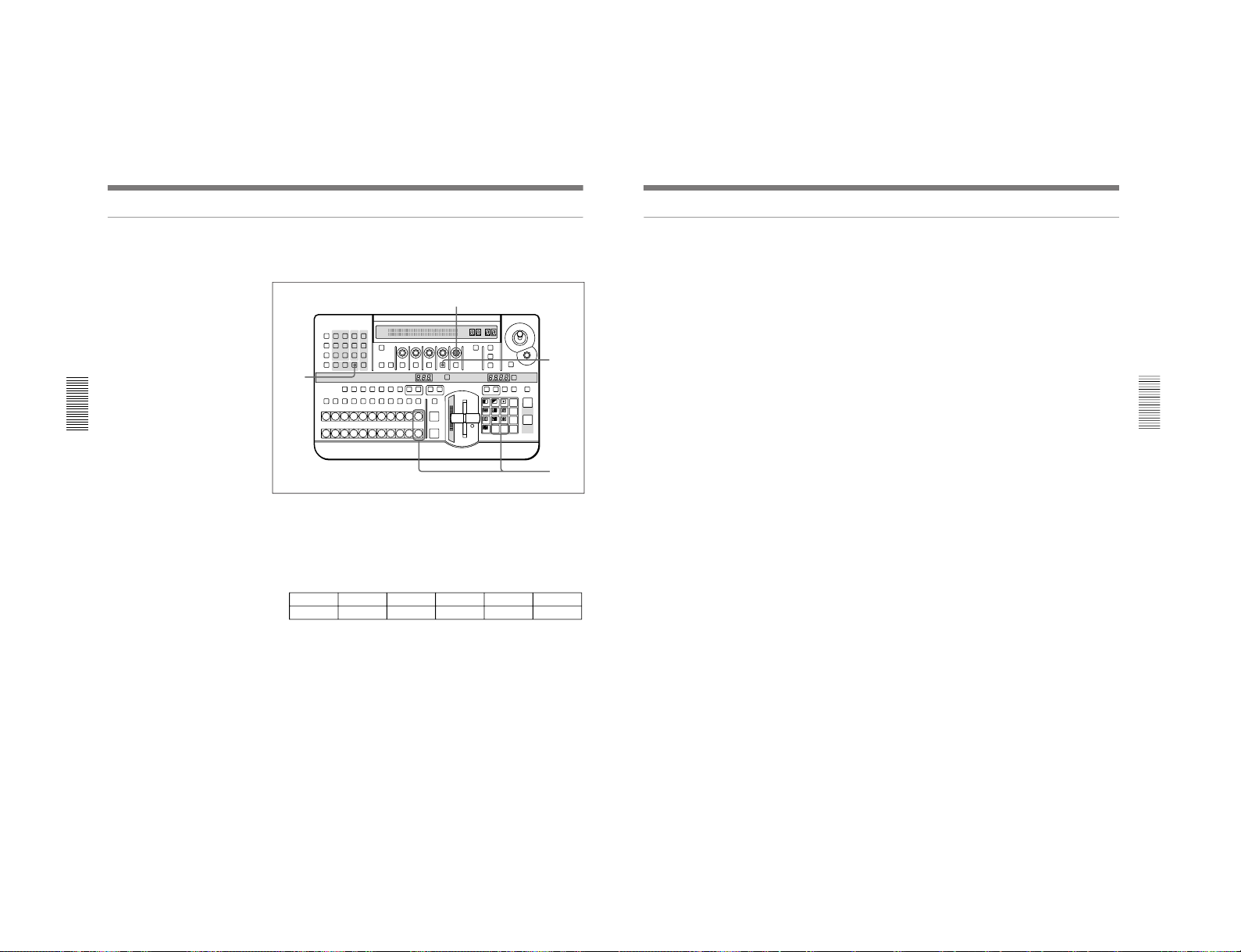
1-21
DFS-700/700P
Chapter 3 Basic Operation
3-14
Chapter 3 Basic Operation
Switching the internal video signal selected by the INT VIDEO button
To switch the internal video signal selected by pressing the INT VIDEO
button on either the background bus or foreground bus, use the following
procedure.
1
Press the MATTES button in the menu control section.
Page 1 of the MATTE menu appears.
2
Press the PAGE button in the effect control section, to display page 2
of the MATTE menu, then press the F4(INTVID) button to select the
desired signal.
MATTE
2/2
FROM
INT V
TO
BORD
COPY
EXEC
INTVID
Matte
PTN
1-80
PA GE F1 F2 F3 F4 F5
You can select any of the following three possibilities.
Matte: color background signal. In the following step 3, you can select
any of plain, or 79 different embossed patterns.
You can adjust the color of the color background signal as desired. For
details, see the section “Adjusting Color Mattes” (page 3-57).
Bar: color bars
Grid: a grid pattern
3
If you have selected a color background signal carry out either of the
following.
•Hold down the INT VIDEO button in the background bus or
foreground bus, and in the pattern/numeric keypad press the UP or
DOWN button.
Each time you press, the pattern changes, and the new pattern appears
on the program monitor.
•Turn the F5(PTN) knob.
LAST X
INS
RST
TITLE
12
EDITOR LUM LUM LUM
DSK EDGE
TRAIL
SHADOW
GPI CRK CRK BORDER BEVELD
EDGE
SET UP MASK MASK MASK SOFT
SHIFT CCR LIGHTING BORDERMATTES
LOCATION
LEARNEDIT
RECALL
HOLD
INPUT
INITIAL
PATTERN
ADJ
PAGE
F1 F2 F3 F4 F5
USER PGM
STATUS EDIT
SNAP SHOT
SET
PATTERN NUMBER
EFFECT
DSK
FTB
SET
TRANS RATE
789
456
123
0
DOWN UP
ENTER
FADE
TO
BLACK
P IN P
DSK
DEL
N/R REV DSK PVWDIRECT
RECALL
DIRECT
PATTERN
CCR TITLE 1
SOURCE
TITLE 2
SOURCE
DSK
FILL
SUPER BGFRGD 2 MEMORY FRAME FREEZ MIX EFFECT
BACKGROUND
BLACK MEMORY INT
VIDEO
TITLE
12345678
CUT
AUTO
TRANS
AUXILIARY
BLACK
MEMORY
INT
VIDEO
12345678
FOREGROUND
BLACK
MEMORY
INT
VIDEO
12345678
PATTERN/KEY PAD
1
3
2
3
Selecting Images
Chapter 3 Basic Operation
Chapter 3 Basic Operation
3-15
Previewing the image after an effect is executed
Select the background image and foreground image, and set up the effect,
then move the fader lever to the opposite end.
You can now check on the program monitor the result of carrying out the
currently set effect.
If a preview monitor is connected, you can check the foreground image on
the preview monitor.
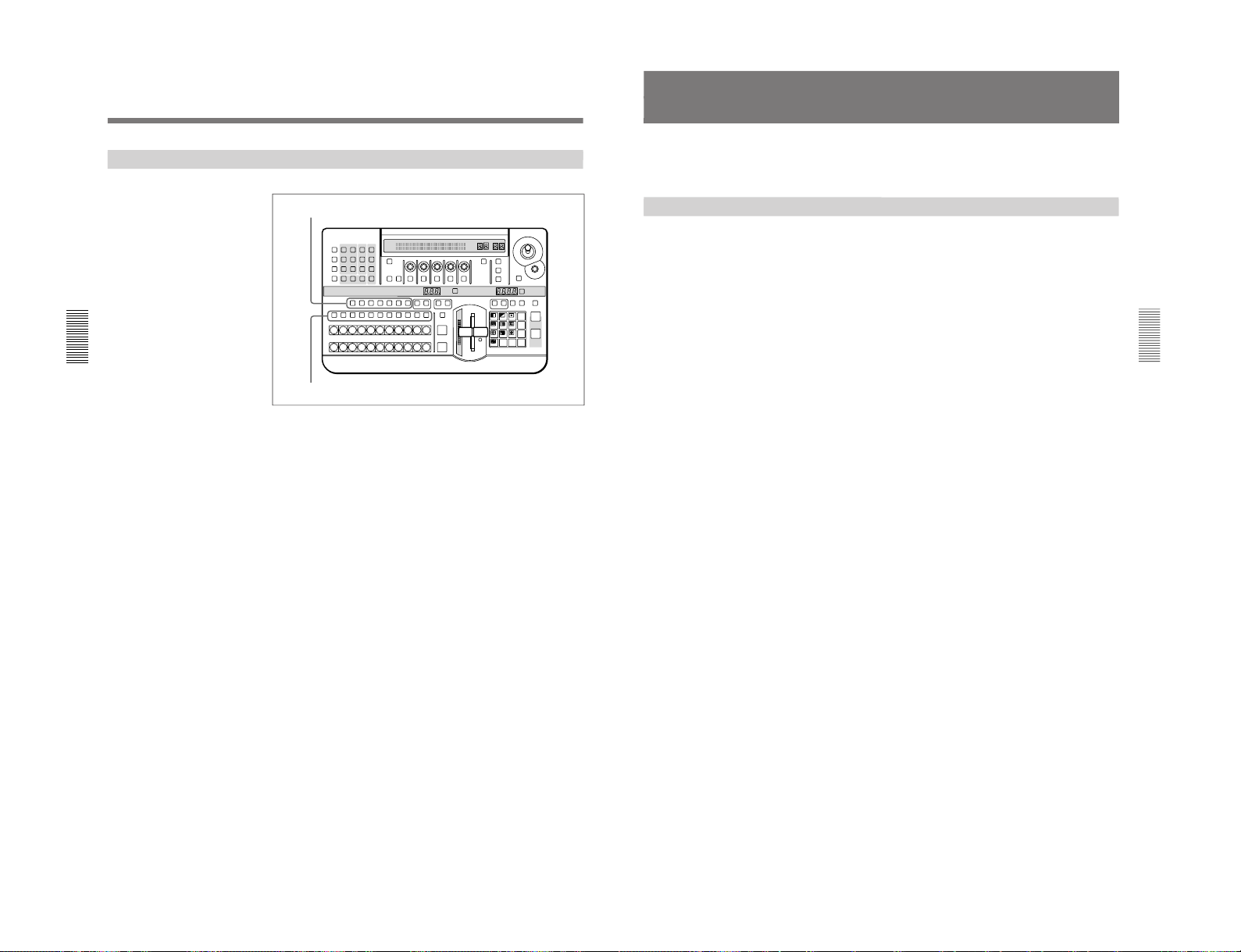
1-22
DFS-700/700P
Chapter 3 Basic Operation
3-16
Chapter 3 Basic Operation
Selecting Signals Output to the Auxiliary Bus
To select the signal to be output to the auxiliary bus, press the desired
AUXILIARY button (BLACK, 1 to 8, MEMORY, or INT VIDEO),
turning it on.
To specify the function for which the selected signal is used, press one of
the delegation buttons, turning it on.
CCR button: use for color correction.
TITLE 1 SOURCE button: use as the key source signal for title key 1.
TITLE 2 SOURCE button: use as the key source signal for title key 2.
DSK FILL button: use as key fill for the downstream keyer.
SUPER BG button: use as background for 3D effects, two-channel
DME effects and so on.
FRGD 2 button: use as the second foreground channel for 3D effects,
two-channel DME effects and so on.
MEMORY button: capture in frame memory.
LAST X
INS
RST
TITLE
12
EDITOR LUM LUM LUM
DSK EDGE
TRAIL
SHADOW
GPI CRK CRK BORDER BEVELD
EDGE
SET UP MASK MASK MASK SOFT
SHIFT CCR LIGHTING BORDERMATTES
LOCATION
LEARNEDIT
RECALL
HOLD
INPUT
INITIAL
PATTERN
ADJ
PAGE
F1 F2 F3 F4 F5
USER PGM
STATUS EDIT
SNAP SHOT
SET
PATTERN NUMBER
EFFECT
DSK
FTB
SET
TRANS RATE
789
456
123
0
DOWN UP
ENTER
FADE
TO
BLACK
P IN P
DSK
DEL
N/R REV DSK PVWDIRECT
RECALL
DIRECT
PATTERN
CCR TITLE 1
SOURCE
TITLE 2
SOURCE
DSK
FILL
SUPER BGFRGD 2 MEMORY FRAME FREEZ MIX EFFECT
BACKGROUND
BLACK MEMORY INT
VIDEO
TITLE
12345678
CUT
AUTO
TRANS
AUXILIARY
BLACK
MEMORY
INT
VIDEO
12345678
FOREGROUND
BLACK
MEMORY
INT
VIDEO
12345678
PATTERN/KEY PAD
Delegation buttons
AUXILIARY buttons
Selecting Images
Chapter 3 Basic Operation
Chapter 3 Basic Operation
3-17
Selecting an Effect
This section describes the types of effects you can use on this system, and
how to select an effect.
Types of Effect
The DFS-700/700P has more than 450 built-in effect patterns provided as
standard.
Each pattern is identified by a number, and the patterns are grouped
together under headings such as “wipe” and “picture-in-picture”.
Transition effects and animation effects
Effects are broadly divided into transition effects and animation effects.
Transition effects: in these effects the background image is completely
replaced by the foreground image. When the effect completes, the
colors in which the BACKGROUND and FOREGROUND bus
buttons are lit become the reverse of those before the effect.
Animation effects: in these effects, for example, the foreground image is
inserted in the background image, and moved around. The foreground
image does not completely replace the background image, and the
colors in which the BACKGROUND and FOREGROUND bus
buttons are lit stay the same.
For the differences between transition and animation effects, see the section
“Background Image and Foreground Image” (page 3-12).
Modifications to effects
Depending on the effect pattern, the following modifications can be added.
•You can add a border to the boundary between the background image and
foreground image, or blur the boundary.
•You can change the pattern position and size.
For details of the modifications that can be applied to the effect patterns, see the
section “Effect Pattern Variant Forms and Decorations” (page A-22).
•You can change a pattern by changing its parameters. (Effects which can
be changed by setting parameters are referred to as “user modifiable
effects”.)
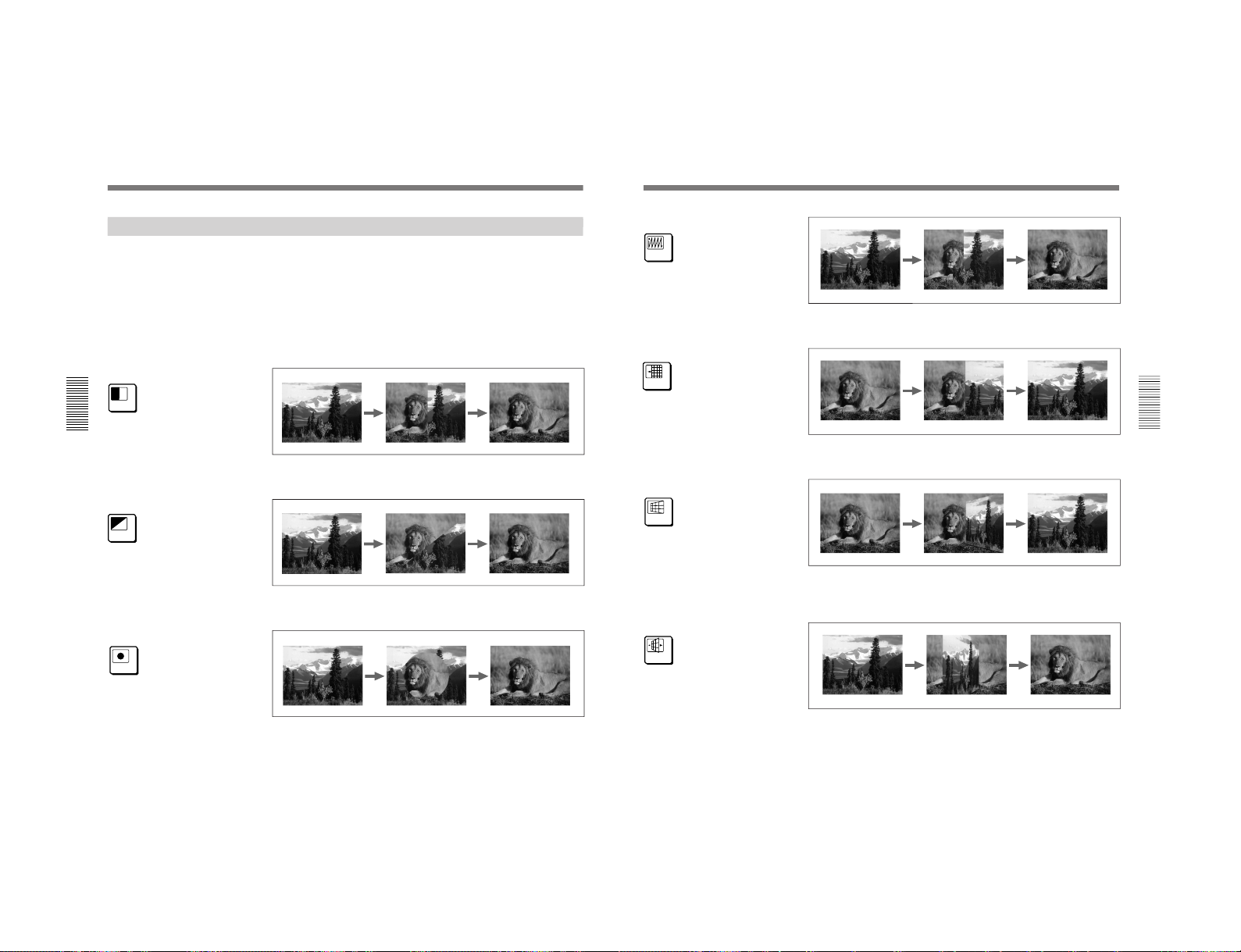
1-23
DFS-700/700P
Chapter 3 Basic Operation
3-18
Chapter 3 Basic Operation
Example Effects
This section shows as examples the effect patterns (“direct patterns”)
which you can access simply by pressing a button in the pattern/numeric
keypad. Note that the effect patterns shown below are the factory default
assignments, and you can change the patterns assigned to buttons 0 to 9
and P IN P/RST.
For details of how to change the assignments, see the section “Changing Direct
Pattern Assignments” (page 4-1).
The foreground image appears from the left, and wipes over the
background image to the right.
The foreground image appears from the upper left corner, and wipes over
the background image to the lower right.
The foreground image appears as a circle in the center of the image, and
this circle grows, wiping over the background image.
7
Pattern number: 1
Effect type: wipe
Motion type: transition
8
Pattern number: 9
Effect type: wipe
Motion type: transition
9
Pattern number: 24
Effect type: wipe
Motion type: transition
Selecting an Effect
Chapter 3 Basic Operation
Chapter 3 Basic Operation
3-19
The foreground image appears in the upper left corner, and fills the screen
in a series of vertical strips.
The foreground image appears from the right, and slides over the
background image to the left.
The foreground image appears as a door rotating toward the viewer to
close, and covers the background. When the door is completely closed, the
foreground fills the screen.
The image rotates about a vertical axis as though a panel with the
background on one side. When the panel reaches 90 degrees to the plane of
the screen, the foreground image appears on the other side, and completely
fills the screen when the transition ends.
4
Pattern number: 700
Effect type: matrix wipe
Motion type: transition
5
Pattern number: 1300
Effect type: slide
Motion type: transition
6
Pattern number: 1700
Effect type: 3D rotation
Motion type: transition
1
Pattern number: 1902
Effect type: flip
Motion type: transition
 Loading...