

Page 1
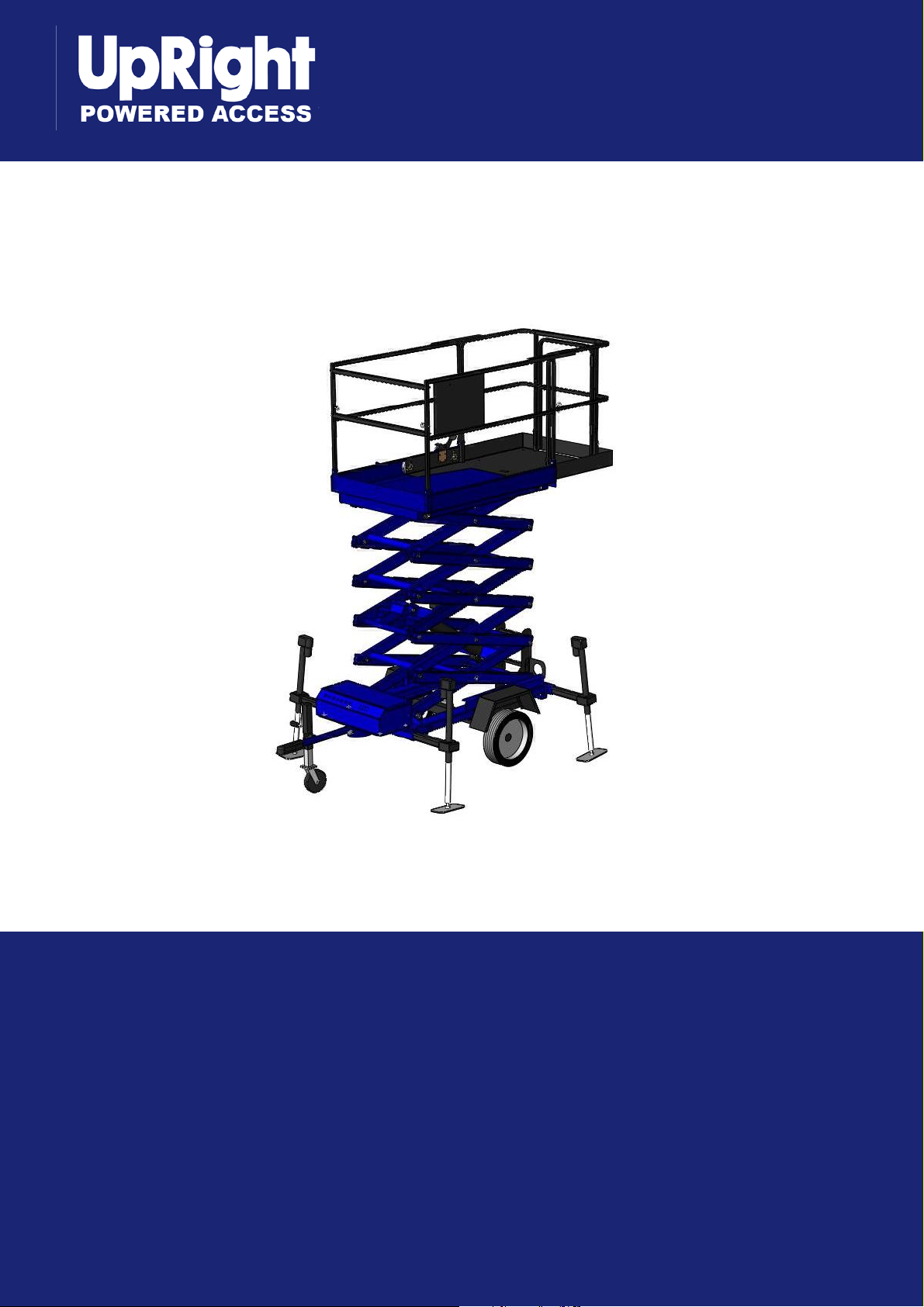
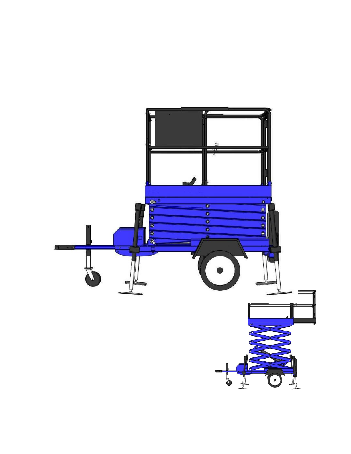
XT24AL
Scissors Lift
Operator Manual
(Maintenance, and Operations)
(EN) Manual part number 510028-000 for serial numbers 10000 to current.
December 08
Page 2

Page 3

EC DECLARATION OF CONFORMITY
FOR MACHINERY
MACHINERY:
Powered Aerial Platform known as:
Type: Upright XT24AL
Serial Number:
The machine specified above conforms to the following provisions:
Machinery directive 98/37/EC (using document EC Community Legislation on Machinery and taking
guidance from EN280:2001 + Amendment A1:2004)
E. C. Type Examination Certificate No:
Note: Modification of the specified unit renders this declaration invalid
XT24AL
Page 4
OPERATION MANUAL
WARNING
All personnel shall carefully read, understand and follow all safety rules and operating
instructions before operating or performing maintenance on any UpRight aerial work platform.
Safety Rules
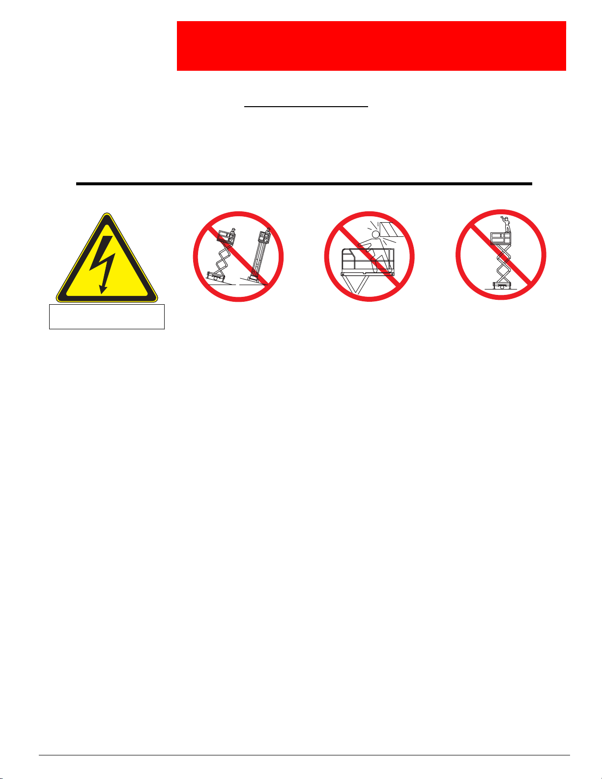
Electrocution Hazard Tip Over Hazard Collision Hazard
THIS MACHINE IS NOT
INSULATED!
USE OF THE AERIAL WORK PLATFORM: This aerial work platform is intended to lift persons and his tools as well as the material
used for the job. It is designed for repair and assembly jobs and assignments at overhead workplaces (ceilings, cranes, roof structures,
buildings etc.). All other uses of the aerial work platform are prohibited!
THIS AERIAL WORK PLATFORM IS NOT INSULATED! For this reason it is imperative to keep a safe distance from live parts of electrical equipment!
Exceeding the specified permissible maximum load is prohibited! See “Special Limitations” on page 4 for details.
The use and operation of the aerial work platform as a lifting tool or a crane (lifting of loads from below upwards or from up high on
down) is prohibited!
NEVER exceed the manual force allowed for this machine. See “Special Limitations” on page 4 for details.
DISTRIBUTE all platform loads evenly on the platform.
NEVER operate the machine without first surveying the work area for surface hazards such as holes, drop-offs, bumps, curbs, or debris;
and avoiding them.
OPERATE machine only on surfaces capable of supporting wheel loads.
NEVER operate the machine when wind speeds exceed this machine’s wind rating. See “Beaufort Scale” on page 4 for details.
IN CASE OF EMERGENCY push EMERGENCY STOP switch to deactivate all powered functions.
IF ALARM SOUNDS while platform is elevated, STOP, carefully lower platform. Move machine to a firm, level surface.
Climbing up the railing of the platform, standing on or stepping from the platform onto buildings, steel or prefab concrete structures, etc.,
is prohibited!
Dismantling the swing gate or other railing components is prohibited! Always make certain that the swing gate is closed and securely
locked!
It is prohibited to keep the swing gate in an open position (held open with tie-straps) when the platform is raised!
To extend the height or the range by placing of ladders, scaffolds or similar devices on the platform is prohibited!
NEVER perform service on machine while platform is elevated without blocking elevating assembly.
INSPECT the machine thoroughly for cracked welds, loose or missing hardware, hydraulic leaks, loose wire connections, and damaged
cables or hoses before using.
VERIFY that all labels are in place and legible before using.
NEVER use a machine that is damaged, not functioning properly, or has damaged or missing labels.
To bypass any safety equipment is prohibited and presents a danger for the persons on the aerial work platform and in its working
range.
NEVER charge batteries near sparks or open flame. Charging batteries emit explosive hydrogen gas.
Modifications to the aerial work platform are prohibited or permissible only at the approval by UpRight.
AFTER USE, secure the work platform from unauthorized use by turning both keyswitches off and removing key.
The driving of MEWPs on the public highways is subject to regulations made under the Road Traffic Acts.
NEVER elevate the platform or drive
the machine while elevated unless the
machine is on a firm, level surface.
NEVER position the platform
without first checking for overhead
obstructions or other hazards.
Fall Hazard
NEVER climb, stand, or sit on
platform guardrails or midrail.
Page 5

Page 6

TABLE OF CONTENTS:
IMPORTANT .................................................10
SAFETY ISSUES ............................................10
DO NOT O PERATE UNLESS YOU: .......................................................................................................................... 10
BATTERY SAFETY ............................................................................................................................... .............. 10
ELECTROCUTION HAZARDS ......................................................................................................................... 11
DAMAGED MACHINE HAZARDS ................................................................................................................... 11
BODILY INJURY HAZARD .............................................................................................................................. 11
TOWING CAUTIONS/WARNING ................................................................................................................ 11
CRUSHING HAZARDS ...................................................................................................................................... 13
OUTRIGGER/LEVELING WARNINGS .......................................................................................................... 13
SAFETY RULES REGARDING PLATFORM USE .......................................................................................... 14
OPERATIONS ................................................15
TOWING PROCEDURE ...................................................................................................................................... 15
PLATFORM........................................................................................................................................................... 16
OUTRIGGER USE ............................................................................................................................................... 17
ELECTRIC OUTRIGGER MANUAL OVER RIDE .......................................................................................... 17
OPERATION OF SCISSORS LIFT .........................17
CONTROLS: ............................................................................................................................... .......................... 17
CONTROL FROM GROUND LEVEL ................................................................................................................ 18
CONTROL THE SCISSORS LIFT FROM THE PLATFORM. ..................................................................... 19
MACHINE CONTROLS WITH OPTION “AUTO-LEVEL” AT
GROUND LEVEL..............................................21
DIAGRAM OF AUTO LEVEL AND VARIABLE HEIGHT ...22
NOTE: On European machines the enable button is moved to the left 3 slots .............................................................. 23
LEVELING PROCEDURE.................................................................................................................................... 23
PROBLEMS WITH MACHINE LEVELING .................................................................................................................. 23
MACHINE CONTROLS WITH OPTION “VARIABLE
HEIGHT” AT GROUND LEVEL ..............................26
ALARMS AND ALARM LIGHTS ..................................................................................................................... 26
- 7 - 8002/13/1
Page 7

MAINTENANCE AND TROUBLE SHOOTING .............27
OUTRIGGER SWITCHES ADJUSTMENT PROCEDURE: ..27
PRECONDITIONS FOR ADJUSTING SWITCHES:.................................................................................................... 28
PROCEDURE FOR PRESSURE SWITCH: ...................................................................................................... 28
PROCEDURE FOR THE PROXIMITY SWITCH: .......................................................................................................... 28
TESTING: ............................................................................................................................................................ 29
HYDRAULIC FLUID LEVEL/TYPE AND MAINTENANCE..29
ROUTINE MAINTENANCE MANUAL ......................29
HYDRAULICS – ATF MERCON/DEXRON III HYDRAULIC OIL ............................................................................ 30
SCISSORS STACK................................................................................................................................................... 30
BATTERY ................................................................................................................................................................. 30
SCISSORS LIFT ARM WEAR PADS........................................................................................................................ 31
ELECTRICAL WIRING............................................................................................................................................. 31
HYDRAULIC TANK CAP VENTING SYSTEM ........................................................................................................... 31
BLEEDING AIR FROM THE HYDRAULIC SYSTEM- SYSTEM “LOCK”........................................................................ 32
TIRES AND WHEELS .............................................................................................................................................. 32
OTHER LUBRICATION ............................................................................................................................................ 33
LEVEL SENSOR- AUDIBLE ALARM .......................................................................................................................... 33
DOCUMENT OF RESPONSIBILITY ........................33
DEFINITIONS:....................................................................................................................................................... 33
DEALER RESPONSIBILITIES: ................................................................................................................................34
RESPONSIBILITIES OF OWNERS:......................................................................................................................... 35
RESPONSIBILITIES OF USERS:............................................................................................................................. 37
RESPONSIBILITIES OF OPERATORS:.................................................................................................................... 42
RESPONSIBILITIES OF LEASERS:......................................................................................................................... 45
RESPONSIBILITIES OF LESSEES: ......................................................................................................................... 45
MAINTENANCE SECTION:.................................47
INSPECTION: ...............................................47
HYDRAULICS – ATF (AUTOMATIC TRANSMISSION
FLUID) MERCON/DEXRON III.............................47
SCISSORS STACK...........................................47
BATTERY .....................................................47
SCISSORS LIFT ARM WEAR PADS........................48
1/31/2008 - 8 -
Page 8

ELECTRICAL WIRING.......................................48
HYDRAULIC TANK CAP VENTING SYSTEM ..............49
BLEEDING AIR FROM THE HYDRAULIC SYSTEM-
SYSTEM “LOCK” .............................................49
TIRES AND WHEELS .......................................50
OTHER LUBRICATION ......................................50
ALARMS (A HORN IN CONTROL BOX AND A RED LIGHT
ON PLATFORM)..............................................50
Outrigger proximity and pressure switches- Audible/Visual alarm.................................................................... 50
Level sensor- Audible/Visual alarm.................................................................................................................... 50
1/31/2008 - 9 -
Page 9

IMPORTANT
Read, understand and obey these safety rules and operation instructions before operating this
machine.
Only trained and authorized personnel shall be permitted to operate this machine.
This manual should be considered a permanent part of your machine and should remain with the
machine at all times.
If you have any questions, call UPRIGHT.
SAFETY ISSUES
Failure to obey the instructions and safety rules in this manual may result in death or serious injury.
Do Not Operate Unless You:
1. Learn and practice the principles of safe machine operation contained in this operator‛s
manual
2. Avoid hazardous situations
3. Know and understand the safety rules before operating the machine
4. Always perform a pre-operation inspection
5. Always perform function tests prior to use
6. Inspect the workplace
7. Only use the machine as it was intended
8. Read, understand and obey
a. Manufacturer‛s instructions and safety rules - safety and operator‛s manuals and decals
b. Employer‛s safety rules and worksite regulations
c. Applicable governmental regulations
9. Are properly trained to operate the machine safely
10. The batteries are charged
BATTERY SAFETY
1. Do not operate the machine with low charge on the batteries.
2. Batteries contain acid. Always wear protective clothing and eyewear when working with
batteries.
3. Avoid spilling or contacting battery acid. Neutralize battery acid spills with baking soda and
water.
4. Do not expose the batteries or the charger to water and/or rain during charging.
5. Keep sparks, flames, and lighted tobacco away from batteries. Batteries emit an explosive
gas, especially during charging.
- 01 - 8002/13/1
Page 10

6. Do not contact the battery terminals or the cable clamps with tools that may cause sparks.
7. Do not use any battery charger greater than nominal 24 Volts to charge the batteries.
8. Avoid electrical shock from contact with battery terminals. Remove all rings, watches and
other jewelry.
ELECTROCUTION HAZARDS
1. This machine is not electrically insulated and will not provide protection from contact with
or proximity to electrical current.
2. Maintain safe distances from electrical power lines and apparatuses in accordance with
applicable governmental regulations.
3. Allow for platform movement, electrical line sway or sag and beware of strong or gusty
winds.
4. Keep away from the machine if it contacts energized power lines. Personnel on the ground
or in the platform must not touch or operate the machine until energized power lines are
shut off.
5. Do not operate the machine during lightning or storms.
6. Do not use the machine as a ground for welding both for operator protection and for
equipment damage.
DAMAGED MACHINE HAZARDS
1. Do not use a damaged or malfunctioning machine.
2. Conduct a thorough pre-operation inspection of the machine and test all functions before
each work shift. Immediately tag and remove from service any damaged or malfunctioning
machine.
3. Be sure all maintenance has been performed as specified in this manual.
4. Be sure the Service Manual is complete, legible and in the storage container located on the
platform.
BODILY INJURY HAZARD
Do not operate the machine with a hydraulic leak. High pressure hydraulic leaks can
penetrate, cut and/or burn skin.
Do not leave a wrench on the electric outrigger over-ride nut located on top of the electric
outriggers.
TOWING CAUTIONS/WARNING
1. Caution should be taken when towing to avoid high speeds and short turns. Unit may tip over
and this could result in death or serious injury.
1/31/2008 - 11 -
Page 11
2. Remove all cargo from the scissors lift before towing. Failure to do this could result in
death or serious injury.
3. Do not operate unit in high speed winds, death or serious injury could occur.
4. Tow only with outriggers in transport position
5. Tow only with extension deck retracted and
pinned
6. Tow only with the deck lowered in transport
position
7. All tires must be properly inflated. Find the
recommended cold tire pressures on the tire
sidewall or trailer decal which is located inside
of the bottom control box. Do not over inflate
the tires. Tire pressures go up during driving.
Checking the tire pressure when the tires are
warm will give you an inaccurate pressure
reading.
8. Increase the distance between your vehicle and
the vehicle in front of you to twice the normal
following distance when towing a trailer. Allow
more following distance in adverse weather.
9. Slow down for downgrades and shift your
transmission into a lower gear.
10. Slow down for curves, hazardous road
conditions, freeway exits, and when driving in
adverse weather. Remember that your PLE Lift
may have a center of gravity that is higher than
the vehicle that is pulling it.
11. When passing other vehicles, be sure to leave
enough room for the extra length of the trailer.
You will need to go farther beyond the past
vehicle before you can return to your lane.
12. When turning with a trailer, avoid jerky or
sudden movements.
13. Heavy winds, excessive speed, load shifting or
passing vehicles can cause the trailer to sway
while driving. If this occurs, do not brake, do not speed up, and do not turn the steering
wheel. Turning the steering wheel or applying the brakes can cause the vehicle and trailer
to jackknife. Let up on the gas pedal and keep the steering wheel straight.
14. If the vehicle and/or trailer inadvertently travel off the paved road, hold the steering
wheel firmly and let up on the gas pedal. Do not apply the brakes. Do not turn sharply.
1/31/2008 - 12 -
Page 12

Slow down to less than 25 mph or 40 km/h. Gradually turn the steering wheel to get back
on the road. Proceed with caution when entering traffic.
15. Always drive slowly when backing a trailer.
16. Keep your hand on the bottom of the steering wheel. Move your hand to the left to turn
the trailer to the left. Move your hand to the right to turn the trailer to the right. Your
PLE Lift has a short wheel base so small moves of the steering wheel have large effects on
the trailer.
17. Be aware of limited sight distance and blind spots when operating.
18. It is recommended that operators wear an approved hard hat when operating the machine.
19. Check the work area for overhead obstructions or other possible hazards.
20. Be aware of crushing hazard when grasping the platform guardrail.
21. Do not operate a machine in the path of any crane or moving overhead machinery unless the
controls of the crane have been locked out and/or precautions have been taken to prevent
any potential collision.
22. Do not lower the platform unless the area below is clear of personnel and obstructions
CRUSHING HAZARDS
1. Keep hands and limbs out of the scissors.
2. Use common sense and planning when operating the machine with the controller from the
ground.
3. Maintain safe distances between the operator, the machine and fixed objects.
OUTRIGGER/LEVELING WARNINGS
1. Do not stand on unit (other than the platform) or attempt to move unit when it is in an
elevated position. Death or serious injury may occur
2. Do not use without outriggers deployed. Death or serious injury may occur
3. Do not operate without outriggers pinned in place. Death or serious injury may occur
4. Do not elevate if machine is not level or on ground that is not firm. Death or serious injury
may occur
5. Do not ride on unit while being towed. Death or serious injury may occur
6. Do not operate unit in winds that exceed 12.5 mps/28 mph. Death or serious injury may
occur
7. Do not exceed weight capacity of 226 kg/500 pounds total weight. If unit is equipped with
the extension deck, 113kg/250 pounds on main deck 113 kg/250 pounds on extension deck.
No more than 2 people on the deck. Death or serious injury may occur
8. Do not stand on handrails. Death or serious injury may occur
9. Do not make contact with electrical wires and electrical fields. Death or serious injury may
occur
1/31/2008 - 13 -
Page 13

10. Do not use without all four outriggers deployed. Death or serious injury may occur
11. Do not operate without all four outriggers pinned in place. Death or serious injury may
occur.
12. Do not elevate this machine if the machine is not leveled in both axis (front to back and side
to side. Death or serious injury may occur.
SAFETY RULES REGARDING PLATFORM USE
1. Do not place or attach fixed or overhanging loads to any part of this machine.
2. Do not place ladders or scaffolds in the platform or against any part of this machine.
3. Be sure all tires are in good condition, lug nuts are properly tightened and cotter pins are
properly installed.
4. Do not use the machine as a crane.
5. Do not contact adjacent structures with the platform.
6. Do not alter or disable the limit switches.
7. Do not operate the machine in strong or gusty winds. Do not increase the surface area of
the platform or the load. Increasing the area exposed to the wind will decrease machine
stability.
8. Do not use the platform controls to free a platform that is caught, snagged or otherwise
prevented from normal motion by an adjacent structure. All personnel must be removed
from the platform before attempting to free the platform using the ground controls
9. Do not push off or pull toward any object outside of the platform.
10. Do not alter or disable machine components that in any way affect safety and stability.
11. Do not modify or alter an aerial work platform. Mounting attachments for holding tools or
other materials onto the platform, toe boards or guardrail systems can increase the weight
in the platform and the surface area of the platform or the load.
12. Do not replace items critical to machine stability with items of different weight or
specification.
13. Do not tie the platform to adjacent structures.
14. Do not place loads outside the platform perimeter.
15. Do not sit on, stand on, or climb on the platform guardrails. Maintain a firm footing on the
platform floor at all times.
16. Do not climb down from the platform when raised.
1/31/2008 - 14 -
Page 14
17. Do not operate the machine unless
the guardrails are properly installed
and the entry is secured for
operation. Attach the platform
entry chain before operating or if
the platform is equipped with a gate,
close and latch the gate before
operating.
18. Do not lower the platform unless the
area below is clear of personnel and
obstructions.
19. Do not attempt to level or operate
with the scissors lift connected to
the towing vehicle.
20. Be sure that the platform extension
in retracted all the way in before
exiting the platform.
OPERATIONS
TOWING PROCEDURE
1. Requires 2 inch (5 cm) ball and coupler
hitch.
2. Attach the trailer chains to the towing
unit, put one chain over another under the
tongue
3. Unit can be towed by any large or small
vehicle, including ATV or golf cart for use
at various locations
1/31/2008 - 15 -
Page 15
4. Your UPRIGHT scissors lift is designed to be towed at highway speeds according to the laws in
your state/country.
PLATFORM
1. Platform size is 48” (1220 mm) x 64” (1625 mm) [48”
(1220 mm) x 94” (2390 mm) with deck extended],
which allows room for a worker and his equipment.
2. Platform weight capability is 500 lb (227 kg).
3. Maximum capacity is two people in the platform or
500 lb (227 kg) total weight.
4. If unit has extension deck, weight capacity is 250 lb
(114 kg) main deck, 250 lb (114 kg) on the extension deck. Do not exceed the maximum
platform capacity or the maximum capacity of the platform extension.
- 61 - 8002/13/1
Page 16

OUTRIGGER USE
1. All four outriggers are to be deployed and pinned when unit is in use.
2. The machine will not operate unless outriggers are deployed, the machine is level and the
outrigger pads are in contact with a firm surface.
3. Machines are fitted with outrigger proximity and pressure switches.
4. Outrigger proximity and pressure switch sensitivity is adjustable. Only qualified
technicians are authorized to make these adjustments. The machine will not operate if
these switches are not in proper adjustment or if they are disabled.
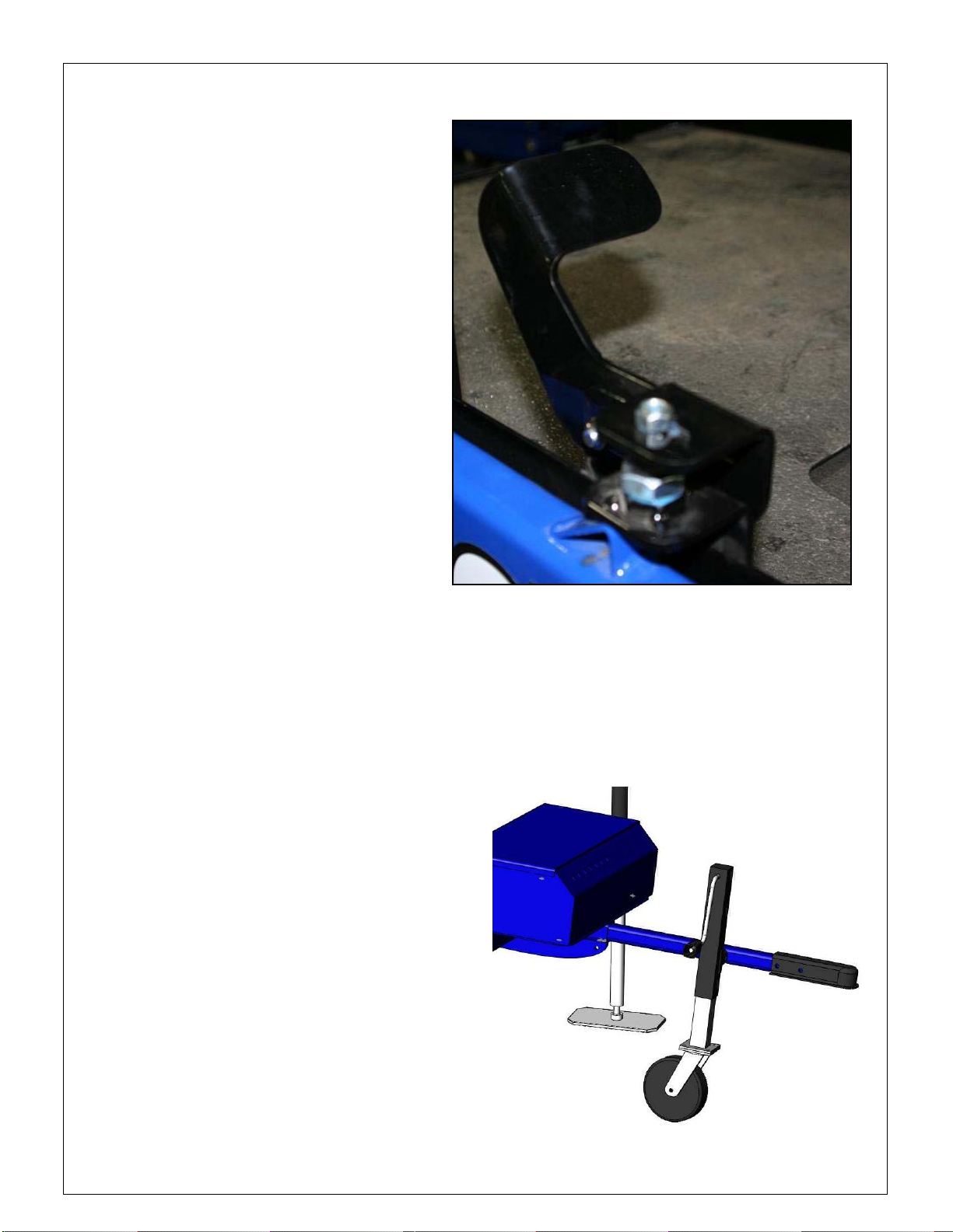
5. Outriggers are to be fully retracted, slid into transport position and pinned for transport.
Please refer to transport pictures in “towing procedure” section of this manual.
Transport Position
ELECTRIC OUTRIGGER MANUAL OVER RIDE
1. The electrical outriggers have a mechanical over-ride. To operate remove the top plastic
cap and turn the 3/8” nut on top.
2. Use only a 3/8” wrench on this hex nut.
3. DO NOT LEAVE THE WRENCH ON THIS NUT UNDER NORMAL OPERATIONS, THAT IS,
WHEN THE MOTOR IS POWERED. THE WRENCH COULD SPIN AND HURT SOMEONE!
OPERATION OF SCISSORS LIFT
1. DO NOT operate the machine with a low charge on the batteries, as indicated by the low
battery light on front of control box.
2. The scissors lift must be on firm ground.
3. The ground slope must not exceed 5 degrees.
4. Select the lift to operate in the ground position. Ensure the scissors lift is operating as
expected. If the scissors lift does not work as expected do not use.
5. Ensure people are clear of the machine, in particular the scissors mechanism has potential
pinch points, see warnings.
CONTROLS:
The lift is equipped with a PLC (Programmable Logic Controller) that controls the operation
of the scissors lift and is located in the main control box in front of the scissors lift. Servicing of
these components should be performed only by trained technicians.
1/31/2008 - 17 -
Page 17

The control panel
CONTROL FROM GROUND LEVEL
The controls are located in the front of the main control box located in the front of the
machine. (See diagram on page 21)
1. To operate the platform from the ground controls, turn key switch to the
ground position.
2. Push the push to enable button while simultaneously twisting the raise/lower
platform button.
3. On the far left is the emergency stop button. To stop machine operation push button in. For
operation this button must be pulled out. (The platform controls also has an emergency stop
button, which must be out for the controls to work.)
4. The next from the left-most button is the enable button.
5. The third control from the left is the outrigger retract button. This red button is operational
if:
a. The platform is all the way down
1/31/2008 - 18 -
Page 18

b. The Emergency stop buttons are not pushed
c. The key switch is on ground control
d. The legs are in the extended position
e. If the PLC is without power for an extended period of time, the button must be held in for
20-30 seconds to override the system. Push and hold the button in until all the legs are fully
retracted. The outriggers are fitted with clutches it will not damage the outrigger legs to
operate with the clutch active. The clutch will ‘click’ when they are engaged.
6. The next green button to the right is the ‘auto level’ switch.
7. Selector switch. This keyed switch is a three position switch. If the switch is in the middle
position the power to the controls is shut off. If the switch is in the left or counter-clock-wise
position the controls are active at platform level. If the switch is in the right position or the
clock-wise position then the controls are active at the ground position.
8. The next control is the up-down selector switch. This switch is active when the far enable
button is pushed. These two controls must be operated together.
9. On the lower left corner of the control box is an emergency lowering handle. Pull (don’t jerk)
this handle to lower the platform in an emergency situation.
CONTROL THE SCISSORS LIFT FROM THE PLATFORM.
The control box on the platform is as pictured. The pre-conditions, the leveling, and the
appropriate selection of the controls on the front of the main control box are assumed. The three
position selector switch located in front of the main box must be rotated to the left or platform
position. The key may be removed by the operator to ensure the personnel on the platform retain
control of the machine.
1/31/2008 - 19 -
Page 19

1. The top control button is the emergency stop. To operate the
machine this button must be out.
2. The next control is a red alarm light. This light is active at the
same time as the alarm horn, which is located inside the main box.
3. The next two switches are the up-down and the push-to-enable
buttons. The push-to-enable button must be pushed to enable the
up-down button. These buttons control the raise/lower functions
of the platform.
4. Climb onto the platform in the back of the lift
5. Close the gate or latch the chain
6. From the platform push the “push-to-enable button”, simultaneously
twist the raise/lower platform button.
1/31/2008 - 20 -
Page 20

Machine controls with option “auto-level” at
ground level
1. Emergency stop button. To stop operation in emergency the button should be pushed in. For
operation this button must be pulled out. (The platform controls also has an emergency stop
button, which must be out for the controls to work.)
2. Selector switch. This keyed switch is a three position switch. If the switch is in the middle
position the power to the controls are shut off. If the switch is in the right or clock-wise
position the controls are active at ground level. If the switch is in the left position or the
counter-clock-wise position, the controls are active on the platform.
3. The raise-lower selector switch. This switch is only active when the enable button is pushed.
These two controls must be operated together. When the enable button is pushed, the up-down
selector controls the platform raise and lower function.
4. The ‘level machine’ button. This button is for auto-level. All the preconditions and set up are
pre-conditions for this button to work. The outriggers, however, must be positioned and the
legs pinned. The machine will ‘auto-level’. That is if the legs are positioned and pinned properly,
the operator must push this green button marked “Level Machine” and the legs will extend and
1/31/2008 - 21 -
Page 21

the machine will level automatically. If the machine does level, several things could cause the
p
g
problem. (See the section “Problems with Machine Leveling.” Page 22)
Diagram of Auto Level and Variable Height
Retract Legs
and Override
Button
Platform and
Ground Key
Raise and
Lower
Controls
Variable
Height
Emergency
Sto
Alarm
Light
Platform
Overload
Low
Volta
e
Emergency
Lowering
1/31/2008 - 22 -
Level
Machine
Button
Push to
Enable
Button
Outrigger
Lights
Down Light
Page 22

NOTE: On European machines the enable button is moved to the left 3 slots
LEVELING PROCEDURE
1. This unit is designed for leveling with the scissors lift disconnected from the towing vehicle
2. This unit is designed to be used with the outriggers deployed and pinned at all times when
not in the trailer configuration
3. Inspect the ground where the jacks will contact. If the ground is soft, move the unit to
firmer ground
4. With the control switch on the control box in either the ground position, push the green
button marked ‘LEVEL MACHINE’
Problems with Machine Leveling
The scissors lift will level itself, unless there is a problem.
Problems could include the following.
1. Dead battery,
1/31/2008 - 23 -
Page 23

2. The slope the machine is on is over five degrees,
3. Either of the two emergency stop buttons is pushed
(one of the emergency stop buttons is on the platform).
4. Failed or out of adjustment of outrigger switches.
5. The ground is soft and the machine settles as the outriggers are
extending.
6. The ground is too rough or un-level such that the legs (or leg) have
reached the extent of their travel. If this condition occurs the operator
rectify the condition before trying again. The machine will not level
of more than five degrees.
7. Failed or out of adjustment of scissors stack position switch.
8. If the machine is mal-functioning. The machine should not
be used until the malfunction is remedied.
1/31/2008 - 24 -
Page 24

1/31/2008 - 25 -
Page 25

Machine controls with option “variable height”
at ground level
Your TP 7000 or TP 9000 can be equipped with a variable height selector option. Activation
of this feature is achieved by turning the selector switch to the “variable height position.” Variable
height selection gives you the option to operate the machine with the outriggers in the “in” or at
their narrowest position. This feature still requires that the outriggers “sense” pressure. The unit
will not operate if the outrigger pads are not firmly on the ground. With the selector turned to the
“variable height” position, you may safely operate the lift to a height of twelve (12) feet. The
machine will automatically stop rising at the twelve foot level. It is important to note: Your TP
7000 or TP 9000 will only rise to its full height with all four (4) of the outriggers in the fully
deployed (extended) position.
ALARMS AND ALARM LIGHTS
•
•
•
•
•
•
1. DOWN ALARM
1/31/2008 - 26 -
Page 26

2. When the platform is being lowered the alarm horn is activated. The purpose for this is to
warn personnel to stand clear of the scissors lift.
3. OUT OF LEVEL ALARM
4. If the alarm light is flashing ½ second on and ½ second off the out of level alarm is on. With
‘OUT OF LEVEL ALARM’ active the scissors lift is not level. See leveling procedure.
5. PLATFORM OVERLOADED
6. If ‘OVERLOADED’ LED is lit the weight rating for the load has been exceeded. The
operator should lower the loading to below the maximum rating. The lift will not operate in
over-loaded condition if it has the optional overload sensing device.
7. LEG POSITION
8. There are four outrigger position indicating lights. These lights must be on to operate the
machine. Exception, the scissors lift may be equipped with the variable height option. These
machines will have a switch on the control box that allows operation at a lower height if on.
The machine is stable to this lower height with the outrigger legs in. If the machine is not
equipped with the green indicator light for variable height the switch will be off, the alarm
light will be lit and the alarm horn will sound. In this state the operator will not be able to
lift the platform.
9. LOW VOLTAGE ALARM
10. If the battery has a low charge the low battery light will be lit. The alarm light will
be lit and the horn will sound. The batteries must be charged before continuing operation of
the lift.
DO NOT OPERATE THE MACHINE WITH LOW
CHARGE ON THE BATTERIES.
MAINTENANCE AND TROUBLE SHOOTING
OUTRIGGER SWITCHES ADJUSTMENT PROCEDURE:
1/31/2008 - 27 -
Page 27

The above drawings show the outrigger switches. The photo on the left shows the
“proximity” switch. The photo on the right is the ‘end’ view of the outrigger switch housing. In this
picture the right side of the housing shows the “pressure” switch and the left side shows the
proximity switch. The outrigger pin must be in place before the proper adjustment of the switches
can be made.
Caution: when inserting the outrigger legs care is needed. Do not force the outrigger leg
into position. The leg must be started in at an angle so as to get past the switches. Then the
outrigger leg can be slid into place. If the legs are forced in the legs will break the switches and
they will have to be replaced.
Preconditions for adjusting switches:
1. The scissors lift should be resting on the tires/wheels, not the outriggers.
2. The outriggers should be in position for lifting. That is the outriggers should be extended
into position so that they are ready to be put in use.
3. The pin holding the outriggers must be inserted so as to position the outrigger properly
(extended).
PROCEDURE FOR PRESSURE SWITCH:
1. Lift the outrigger leg so that it is not resting on the frame and is lifted high enough so that
it is in the same position with regard to the frame as it would be if the outrigger was
holding up the frame.
2. Loosen the adjustments screws so that the pressure switch can be moved.
3. Move the switch up then down.
4. While moving it down a slight click can be heard – that click is the switch opening.
5. Slowly lift the switch until a click is heard a second time. This click is the switch closing.
The switch should be moved only slightly so that the opening and closing of the switch will
happen when the outrigger leg is lifted or lowered.
6. Tighten that switch. This switch should now be calibrated.
Procedure for the proximity switch:
1. The proximity switch handle or leg should be directly over the detent in the outrigger leg.
2. Loosen the proximity switch screws.
3. Lift the leg
4. Lift the switch and then lower it until a click can be detected.
5. Raise the switch until the click can be detected the switch should be lifted slightly.
6. Tighten the proximity switch screws.
1/31/2008 - 28 -
Page 28

7. Test the switch by removing the outrigger retention pin, move the outrigger in and out while
the outrigger leg is held with slight upward pressure. The proximity switch should open and
close as the outrigger leg is moved in and out.
8. Extend the outrigger leg and replace the retention pin.
9. The proximity switch should be calibrated.
TESTING:
1. Ensure everything is properly adjusted by lowering the outrigger leg so as to slightly lift
the corner of the scissors jack. With a continuity tester check to see if there is continuity
across the contacts of the switches. If there is not continuity then the procedure must be
redone.
2. Next lift the outrigger leg so that there is no pressure on the leg. There should no longer
be continuity across the contacts on the pressure switch.
3. Pull the outrigger retention pin
4. Move the outrigger leg in about 5 cm.
5. Lower the outrigger leg until there is upward pressure.
6. test continuity across the proximity switch, there should be no continuity,
The outrigger should now be ready for use.
HYDRAULIC FLUID LEVEL/TYPE AND MAINTENANCE
1. Use ATF Mercon/Dexron-III fluid to refill unit
2. Check snap rings on scissors sections before each use. Replace any missing, broken or loose
nuts and bolts
3. Check and refill hydraulic fluid before each use. Fluid level should be 5 cm below top of fill
tube.
4. Check the tire pressure, hydraulic hose and electrical wires for abrasions and cuts before
each use. Replace damaged items.
5. Inspect outriggers and pins for damage and cracks before each use and once a year check
and grease wheel bearings
ROUTINE MAINTENANCE MANUAL
1. Inspect machine for any metal fatigue or wear. Do not use if any cracked welds are found.
Cease operation and contact UPRIGHT. if any defects are found. Refer to UPRIGHT
pre-delivery and inspection report for additional information
- 92 - 8002/13/1
Page 29

2. Check pinned connections on outriggers. The outrigger retaining pins are to be removed and
each outrigger is to be pulled out of its transport position. Replace the outrigger in a
vertical position so that the outrigger pad faces down. Replace the security pin from where
it was removed with the outrigger in its extended position. Always replace the spring loaded
security pin in each outrigger pin.
3. The outrigger is held in place with a hitch-type pin and a hairpin clip. Do not use if the pin
or clip is missing. Replace before use.
4. Check to see that the deck gate chain is in place. Do not use machine if the chain is missing.
Hydraulics – ATF Mercon/Dexron III Hydraulic Oil
1. Check hoses for any leaks or wear.
2. Check oil level in the reservoir. Oil level should be 2” below the top of fill tube when the
lift is fully lowered. Total oil capacity is 3 gallons. Do not overfill as this will result in fluid
discharge from the tank vent plug.
3. Vent plug on cylinder should be free of external debris. Do not use lift if vent plug on
cylinder is missing. Replace vent plug with factory supplied plug before use.
Scissors Stack
1. Check scissors stack connections for wear.
2. A washer and external snap ring hold stack sections in place. Do not operate lift if snap ring
or washer is missing. Replace before use.
3. Scissors stack sections require no lubrication
Battery
Proper battery condition is essential to good machine performance and operational safety.
Improper fluid levels or damaged cables and connections can result in component damage and
hazardous conditions.
1. Put on protective clothing and eyewear.
2. Be sure that the battery cable connections are free of corrosion.
1/31/2008 - 30 -
Page 30

3. Be sure that the battery retaining fasteners and cable connections are tight.
4. Inspect the battery charger plug and pigtail for damage or excessive insulation wear.
Replace as required.
5. Connect the battery charger to a properly grounded AC power supply.
6. You can expect a minimum of 35 to 75 complete up and down cycles from your UPRIGHT Lift.
7. Eight hours are required to completely recharge your machine with the onboard automatic
charger
Scissors Lift Arm Wear Pads
Maintaining the scissor arm wear pads is essential to safe machine operation. Continued use
of worn out wear pads may result in component damage and unsafe operating conditions. Apply a thin
layer of dry film lubricant to the area of the chassis where the scissor arm wear pads make
contact.
Electrical Wiring
Maintaining electrical wiring in good condition is essential to safe operation and good
machine performance. Failure to find and replace burnt, chafed, corroded or pinched wires could
result in unsafe operating conditions and may cause component damage.
WARNING: Electrocution hazard. Contact with hot or live circuits could result in
death or serious injury. Remove all rings, watches and other jewelry.
1. Inspect the underside of the chassis for damaged or missing wires.
2. Inspect the following areas for burnt, chafed, corroded and loose wires:
a. Ground control box
b. Scissors arms
c. Platform controls
WARNING: Crushing hazard. Keep hands clear of the safety arm when lowering
the platform.
Inspect the center chassis area and scissor arms for burnt, chafed and pinched cables.
1. Scissor arms
2. Power to platform controls
3. Power to platform wiring
Hydraulic Tank Cap Venting System
A free-breathing hydraulic tank cap is essential for good machine performance and service
life. A dirty or clogged cap may cause the machine to perform poorly. Extremely dirty conditions
may require that the cap be inspected more often.
1. Remove the breather cap from the hydraulic tank
2. Check for proper venting.
- 13 - 8002/13/1
Page 31

RESULT: If the air does not pass through the cap, clean or replace the cap.
NOTICE: When checking for positive tank cap venting, air should pass freely
through the cap.
Using a mild solvent, carefully wash the cap venting system. Dry the venting system by
using low-pressure compressed air. Repeat vent check.
Install the breather cap onto the hydraulic tank.
The hydraulic tank is a vent-type tank. The breather cap has an internal air filter that can
become clogged or, or over time, can deteriorate. If the breather cap is faulty or improperly
installed, impurities can enter the hydraulic system, which may cause component damage.
Extremely dirty conditions may require that the cap be inspected more often.
1. Remove and discard the hydraulic tank breather cap
2. Install a new cap onto the tank.
Bleeding air from the hydraulic system- System “lock”
It may be necessary to “bleed” air from the hydraulic system after service has been
performed. If the system is not free of air, the safety system will activate and the “velocity
fuse” in the manifold will “lock” the machine. This lock can be over-ridden by pulling the manual
release at the same time as you raise the machine.
Please follow the following procedure:
1. Locate the hydraulic return line (located at the top of pump)
2. Remove line and place this line in a container.
3. Pull (don’t jerk) manual release (emergency lowering valve located at the back of machine)
and have an assistance raise machine at the same time until oil comes out of the hose.
(Usually takes about two seconds) be careful as air and oil will exit the system with some
velocity.
4. Release manual release and raise lift. It will be necessary to add oil to the system when the
lift platform reaches ten feet of elevation.
5. Extend the platform until it hits the cylinder stop (twenty-four feet) and reconnect the
hydraulic return line.
6. Lower unit and cycle system.
Tires and Wheels
Maintaining the tires and wheels in good condition is essential to safe operation and
good performance. Tire and/or wheel failure could result in a machine tip-over. Component
damage may also result if problems are not discovered and repaired in a timely fashion.
1. Check the tire surface and sidewalls for cuts, cracks, punctures and unusual wear.
2. Check each wheel for damage, bends, or cracks.
1/31/2008 - 32 -
Page 32

Other lubrication
Grease zerks are provided on both the top and bottom ends of the main hydraulic cylinder.
Lift the machine and place the safety prop in position in order to grease these fittings.
Level sensor- Audible alarm
The level sensor is designed to give an audible signal at out of level attitudes of 2 degrees
front to back and 2 degrees side to side. The level sensor is pre-set at the factory and it is leveled
with the frame of the machine using three bracket bolts with spring tension on them. Always level
the machine to the frame using both the indication level on the sensor and a four foot contractor’s
level.
DOCUMENT OF RESPONSIBILITY
Definitions:
Aerial Platform - a manually propelled device that has an adjustable position platform, supported
from ground level by a structure
Authorized Personnel (authorized person) -personnel approved or assigned to perform a specific
type of duty or duties at a specific location or locations at a work site
Base - the relevant contact points of the aerial platform that form the stability fulcrum (e.g.,
wheels, casters, outriggers, stabilizers)
Chassis - the integral part of the aerial platform that provides mobility and support for the
elevating assembly
Configuration - all positions in which an aerial platform or any part thereof can be placed within its
intended operating limits
Dealer - a person or entity who buys from a manufacturer or distributor and who generally sells,
rents, and services aerial platforms
Delivery - transfer of care, control, and custody of the aerial platform from one person or entity to
another person or entity
Elevating Assembly - the mechanisms used to position the platform relative to the aerial platform
chassis
Guardrail System - a vertical barrier intended to prevent personnel from falling to lower levels
Hazardous Location - any location that contains, or has the potential to contain an explosive or
flammable atmosphere
Instability - a condition in which the sum of the moments that tend to overturn the aerial platform
exceeds the sum of the moments tending to resist overturning
Insulated Platform - a platform designed and tested to meet the specific electrical insulation
ratings consistent with the manufacturer's identification plate
1/31/2008 - 33 -
Page 33

Interlock - A control or mechanism that, under specified conditions, automatically allows or
prevents the operation of another control or mechanism
Manufacturer - A person or entity, who makes, builds, or produces an aerial platform
Modification, Modified - to make a change(s) to an aerial platform that affects the operation,
stability, safety factors, rated load, or safety of the aerial platform in any way
Operator - A qualified person who controls the movement of an aerial platform
Outriggers - Devices that increase the stability of the aerial platform and that are capable of
lifting and leveling the aerial platform
Owner - A person or entity that has possession of an aerial platform by virtue of proof of purchase
Platform - The portion of an aerial platform intended to be occupied by personnel with their
necessary tools and materials
Platform Height - The vertical distance measured from the floor of the platform to the surface
upon which the machine is being supported
Qualified Person - a person who by reason of knowledge, experience, or training is familiar with the
operation to be performed and the hazards involved
Rated Work Load - the designed carrying capacity of the aerial platform as specified by the
manufacturer
Shall - The word "shall" is to understood as mandatory
Stability - A condition in which the sum of the moments that tend to overturn the aerial platform is
less than the sum of the moments tending to resist overturning
User - A person(s) or entity that utilizes or puts into operation an aerial platform
Dealer Responsibilities:
Sound principles of safety, training, inspection, maintenance, applications, and operation
consistent with all data available regarding the parameters of intended use and expected
environment shall be applied in the training of operators, in maintenance, application, and operation
of the aerial platform with due consideration of the knowledge that the unit will be carrying
personnel.
Dealers shall keep and maintain a copy of the operation and maintenance manual stored in
the manual tube of the machine. A copy of the operations manual shall be provided upon each rental
or lease delivery.
Aerial platforms shall be inspected, serviced, and adjusted to manufacturer’s requirements
prior to each delivery by sale, lease or rental. A pre-inspection checklist is provided within each
operations and maintenance manual.
Before adjustments and repairs are started on an aerial platform, the following precautions
shall be taken as applicable:
1. All controls in the "off" position and all operating features secured from inadvertent motion
by brakes, blocks or other means.
2. Power plant stopped and starting means rendered inoperative.
1/31/2008 - 34 -
Page 34

3. Platform lowered to the full down position, if possible, or otherwise secured by locking or
cribbing to prevent dropping.
4. Hydraulic oil pressure relieved from all hydraulic circuits before loosening or removing
hydraulic components.
5. Safety props or latches installed where applicable as described by the manufacturer.
When parts or components are replaced, they shall be identical or equivalent to original
aerial platform parts or components.
Whenever a dealer directs or authorizes an individual to operate an aerial platform, the
dealer shall ensure that the individual has been trained under the direction of a qualified person in
accordance with the manufacturer's operating and maintenance manual.
Manufacturer's operating instruction and required training on the proper use and operation
of the aerial platform shall be provided upon each delivery, by sale, lease, or rental.
When a dealer operates an aerial platform in sales demonstrations or for other beneficial
use, the dealer shall assume the responsibilities of users and the operating personnel shall assume
the responsibilities of operators.
The dealer is responsible for obtaining the proper information from the manufacturer and
providing that information to the owner or user involving questions related to all aspects of the
aerial platform.
Dealers shall retain the following records for at least 3 years:
1. Name and address of the purchaser of each aerial platform by serial number and the date
of delivery.
2. Records of the person(s) trained upon each delivery of an aerial platform
3. Records of the pre-delivery preparation performed prior to each delivery
Modifications or alterations of aerial platforms shall be made only with prior written
permission of the manufacturer.
The dealer shall comply with safety-related bulletins as received from the manufacturer.
Responsibilities of Owners:
Sound principles of safety, training, inspection, maintenance, application, and operation
consistent with all data available regarding the parameters of intended use and expected
environment shall be applied in the performance of the responsibilities of owners with due
consideration of knowledge that the unit will be carrying personnel.
Owners shall keep and maintain a copy of the operation and maintenance manual stored in
the manual tube of the machine. A copy of the operations manual shall be provided upon each rental
or lease delivery. These manual(s) are considered an integral part of the aerial platform and are
vital to communicate necessary safety information to users and operators.
The owner of an aerial platform shall arrange that the maintenance specified in the
standard is properly performed on a timely basis. The owner shall establish a preventive
maintenance program in accordance with the manufacturer's recommendations and based on the
1/31/2008 - 35 -
Page 35

environment and severity of use of the aerial platform. The owner shall arrange that frequent and
annual inspections are performed. All malfunctions and problems noted shall be corrected before
the aerial platform is returned to service.
1. The owner of an aerial platform shall cause a frequent inspection to be performed on an
aerial platform:
2. That has been in service for 3 months.
3. That has been out of service for a period longer than 3 months.
4. The inspection shall be made by a person qualified as a mechanic on the specific make and
model of the aerial platform.
5. The inspection shall include all items specified by the manufacturer for a frequent
inspection and shall include, but not be limited to, the following:
6. All functions and their controls for speed(s), smoothness, and limits of motion.
7. Emergency lowering means.
8. All chain and cable mechanisms for adjustment and worn or damaged parts.
9. All emergency and safety devices
10. Lubrication of all moving parts, inspection of filter element(s), hydraulic oil, engine oil, and
coolant, as specified by the manufacturer.
11. Visual inspection of structural components and other critical components, such as fasteners,
pins, shafts, and locking devices.
12. Placards, warnings, and control markings.
13. Items specified by the manufacturer.
14. Correction of all malfunctions and problems identified and further inspection.
The owner of an aerial platform shall cause an annual inspection to be performed on the
aerial platform no later than 13 months from the date of the prior annual inspection. The
inspection shall be made by a person qualified as a mechanic on the specific make and model of the
aerial platform. The inspection shall include all items specified by the manufacturer for an annual
inspection as listed in the operations and maintenance manual.
Before adjustments and repairs are started on an aerial platform, the following precautions
shall be applicable:
1. All controls in the "off" position and all operating features from inadvertent motion by
brakes, blocks, or other means.
2. Power source disconnected/stopped and starting means rendered inoperative
3. Platform lowered to the full down position, if possible, or otherwise secured by blocking or
cribbing to prevent dropping
4. Hydraulic oil pressure relieved from all hydraulic circuits before loosening or removing
hydraulic components
1/31/2008 - 36 -
Page 36

5. Safety props or latches installed where applicable as described by the manufacturer
When parts or components are replaced, they shall be identical or equivalent to original
aerial platform parts or components.
The owners shall train their maintenance personnel in inspection and maintenance of the
aerial platform and with the manufacturer's recommendations.
An owner who directs or authorized an individual to operate an aerial platform shall ensure
that the individual has been trained in accordance with the manufacturer's operating manual before
operating the aerial platform. Manufacturer's operating instruction and required training on the
proper use and operation of the aerial platform shall be provided upon each delivery, by sale, lease,
or rental.
When the owner operates an aerial platform, the owner shall have the responsibilities of
users of this standard, and the operating personnel shall have responsibilities of Operators as
listed in this Document of Responsibility.
If an owner is unable to answer a user's or operator's questions relating to capacity,
intended use, maintenance, repair, inspection, or operation of the aerial platform, the owner shall
obtain the proper information from the dealer or manufacturer and provide that information to the
user or operator.
The owner shall retain the following records for at least three years:
1. Name and address of the purchaser of each aerial platform by serial number and date of
delivery
2. Records of the person(s) trained upon each delivery of an aerial platform
3. Written records of the frequent and annual inspections performed by the owner. The
record shall include deficiencies found, corrective action, and identification of the person(s)
performing the inspection and repairs
4. Records of the pre-delivery preparation performed prior to each delivery
The owner shall not modify or concur in modification or alteration to the aerial platform
without the modifications being approved and certified in writing by the manufacturer.
The owner shall comply with safety-related bulletins as received from the manufacturer or
dealer.
Responsibilities of Users:
The information in this standard must be supplemented by good job management, safety
control, and the application of sound principles of safety, training, inspection, maintenance,
application and operation consistent with all data available regarding the parameters of intended
use and expected environment. Since the user has direct control over the application and operation
of aerial platforms, conformance with good safety practices in this area is the responsibility of the
user and the operating personnel, including the operator. Decisions on the use and operation of the
aerial platform must always be made with due consideration for the fact that the machine will be
carrying personnel whose safety is dependent on those decisions.
1/31/2008 - 37 -
Page 37

Users shall keep and maintain a copy of the operation and maintenance manual stored in the
manual tube of the machine. These manual(s) are considered an integral part of the aerial platform
and are vital to communicate necessary safety information to users and operators.
Users shall inspect and maintain the aerial platform as required to ensure proper operation.
The frequency of inspection and maintenance shall be determined by the manufacturer's
recommendation and be compatible with operating conditions and the severity of the operating
environment. Aerial platforms that are not in proper operating condition shall be immediately
removed from service until repaired. Repairs shall be made by qualified personnel and the repairs
shall be in conformance with the manufacturer's recommendations.
An inspection as outlined in the Operations and Maintenance Manual shall be conducted.
An annual inspection shall be performed on the aerial platform no later than 13 months from
the date of the prior annual inspection. The inspection shall be made by a person qualified as a
mechanic on the specific make and model of the aerial platform. The inspection shall include all
items specified by the manufacturer for an annual inspection as listed in the Operations and
Maintenance Manual.
Before each day or at the beginning of each shift, the aerial platform shall be given a visual
inspection and functional test including but not limited to the following:
1. Operating and emergency controls
2. Safety devices
3. Personal protective devices, including fall protection
4. Air, hydraulic and fuel system leaks
5. Cables and wiring harness
6. Loose or missing parts
7. Tires and wheels
8. Placards, warnings and control markings
9. Outriggers, stabilizers, and other structures
10. Guardrail system
11. Items specified by the manufacturer
Before adjustments and repairs are started on an aerial platform, the following precautions shall be
applicable:
1. All controls in the "off" position and all operating features from inadvertent motion by
brakes, blocks, or other means.
2. Power source disconnected/stopped and starting means rendered inoperative
3. Platform lowered to the full down position, if possible, or otherwise secured by blocking or
cribbing to prevent dropping
4. Hydraulic oil pressure relieved from all hydraulic circuits before loosening or removing
hydraulic components
1/31/2008 - 38 -
Page 38

5. Safety props or latches installed where applicable as described by the manufacturer
When parts or components are replaced, they shall be identical or equivalent to original
aerial platform parts or components.
The user shall train their maintenance personnel in inspection and maintenance of the aerial
platform and with the manufacturer's recommendations.
Whenever a user directs or authorizes an individual to operate an aerial platform, the user
shall ensure that the individual has been trained in accordance with the manufacturer's operating
and maintenance manual, the user's work instructions, and the requirements listed in Users
Responsibilities of this standard before operating the aerial platform.
The user shall be responsible for the operator being trained on the model of the aerial
platform to be operated. Such training shall be in an area free of obstructions, under the direction
of a qualified person for a time sufficient to determine that the trainee displays proficiency in
knowledge and actual operation of the aerial platform. Only properly trained and authorized
personnel shall be permitted to operate the aerial platform.
A record of the trainee's aerial platform instruction shall be maintained by the user for at
least 3 years.
Before authorizing an operator to operate an aerial platform, the user shall ensure that the
operator has:
1. Been instructed by a qualified person in the intended purpose and function of each control
2. Read and understood the manufacturer's operating instructions and user's safety rules, or
been trained by a qualified person on the contents of the manufacturer's operating
instructions and user's safety rules
3. Understood by reading or by having a qualified person explain all decals, warnings, and
instructions displayed on the aerial platform
4. Determine that the purpose for which the aerial platform is to be used is within the scope
of the intended applications defined by the manufacturer
5. Been provided with approved fall protection devices and other safety gear for all personnel
of the platform
6. Before the aerial platform is used and during use, the user shall check the area in which the
aerial platform is to be used for possible hazards such as, but not limited to:
7. Drop-offs or holes
8. Bumps and floor obstructions
9. Debris
10. Overhead obstructions and high voltage conductors
11. Hazardous locations
12. Inadequate surface and support to withstand all load forces imposed by the aerial platform
in all operating configurations
13. Wind and weather conditions
1/31/2008 - 39 -
Page 39

14. Other possible unsafe conditions
15. Presence of unauthorized persons
The aerial platform shall be used in accordance with this Document of Responsibility and
the Operations and Maintenance Manual. The user shall direct the operator to ensure the following
before each elevation of the platform:
6. That the aerial platform is operated on a surface within the limits specified by the
manufacturer
7. That the outriggers, stabilizers, extendable axles, or other stabilizing methods are used as
required by the manufacturer
8. That the guardrails are installed and access gates or openings are closed per
manufacturer's instructions
9. That the load and its distribution on the platform and any platform extension are in
accordance with the manufacturer's rated capacity for that specific configuration
10. That there is adequate clearance from overhead obstructions
11. That the minimum safe approach distances to energized power lines and parts, as listed are
maintained.
12. That the precautions that are listed in this document are followed during operation of the
aerial platform
IT SHALL BE THE RESPONSIBILITY OF THE USER TO DETERMINE THE HAZARD
CLASSIFICATION OF ANY PARTICULAR ATMOSPHERE OR LOCATION.
The user shall direct his operating personnel and supervise the work to ensure operation is
in compliance with the requirements of the following statements of warning and instruction.
Personnel Footing - Personnel shall maintain a firm footing on the platform floor while
working thereon. Use of planks, ladders, or any other device on the aerial platform for achieving
additional height or reach shall be prohibited.
Other Moving Equipment - When other moving equipment or vehicles are present, special
precaution shall be taken to comply with local ordinances or safety standards established for the
workplace. Warnings such as, but not limited to, flags, roped-off areas, flashing lights, and
barricades shall be used.
Reporting Problems or Malfunctions - The operator shall immediately report to the
supervisor any problems or malfunctions that become evident during operation. Any problems or
malfunctions that affect the safety or operations shall be repaired prior to continued use of the
aerial platform.
Altering Safety Devices - Altering or disabling of interlocks or other safety devices shall
be prohibited.
Entanglement - Care shall be taken to prevent rope, electric cords, hoses, etc., from
becoming entangled in the aerial platform.
- 04 - 8002/13/1
Page 40

Capacity Limitation - Aerial platform rated capacities shall not be exceeded when loads are
transferred to the platform at any height.
Work Area - The operator shall ensure that the area surrounding the aerial platform is
clear of personnel and equipment before lowering the platform.
Battery Charging - Batteries shall be charged in a well-ventilated area free of flame,
sparks, or other hazards that may cause fire or explosion.
Platform Positioning - The aerial platform shall not be positioned against another object to
steady the platform.
Misuse as a Crane - The aerial platform shall not be used as a crane.
Operating Areas - The aerial platform shall not be operated from a position on trucks,
trailers, railway cars, floating vessels, scaffolds, or similar equipment, unless the application is
approved in writing by the manufacturer.
Travel Conditions - Under all travel conditions, the operator shall limit travel speed
according to conditions of ground surface, congestion, visibility, slope, location of personnel, and
other factors causing hazards of collision or injury to personnel.
Unauthorized Use - Means shall be used to protect against use by unauthorized person(s).
Operation of the Aerial Platform - If a user is also the operator of an aerial platform, the
user shall have the responsibilities of operators specified in Responsibilities of Operators section
of this standard as well as Responsibilities of Users as specified in this Document of Responsibility.
Assistance to Operator - If a user is unable to answer any operator's questions relating to
rated capacity, intended use, maintenance, condition, or safety of operation of the aerial platform,
the user shall obtain the proper information from the dealer, owner, or manufacturer and provide
that information to the operator before use of the aerial platform in the application of concern.
Shutdown of Aerial Platform - The user shall authorize and direct the operating personnel
to cease operation of the aerial platform in case of any suspected malfunctions of the aerial
platform, or any hazard or potentially unsafe condition that may be encountered, and to request
further information as to safe operation from the owner, dealer, or manufacturer before further
operation of the aerial platform.
Record Retention - The user shall retain the following records for at least 3 years:
1. Records of the operator(s) trained on each model of an aerial platform.
2. Written records of the frequent and annual inspections shall be kept by the user when
performing the inspections. The records shall include the date of inspection, any
deficiencies found, the corrective action recommended and identification of the person(s)
performing the repair.
3. Written records of all repairs accomplished on the aerial platform, including the date of any
such repair, a description of the work accomplished, and the identification of the person(s)
performing the repair.
Modifications - A user shall not modify or concur in modification of an aerial platform
without the specific written approval of the manufacturer of the aerial platform.
1/31/2008 - 41 -
Page 41

Manufacturer's Safety Bulletins - The user shall comply with safety-related bulletins as
received from the manufacturer, dealer, or owner.
Responsibilities of Operators:
The information in this standard must be supplemented by good job management, safety
control, and the application of sound principles of safety, training, inspection, maintenance,
application and operation consistent with all data available regarding the parameters of intended
use and expected environment. Since the user has direct control over the application and operation
of aerial platforms, conformance with good safety practices in this area is the responsibility of the
user and the operating personnel, including the operator. Decisions on the use and operation of the
aerial platform must always be made with due consideration for the fact that the machine will be
carrying personnel whose safety is dependent on those decisions.
The operator shall be aware that the operating and safety manuals, including the manual
that defines the responsibilities of dealers, owners, leasers, lessees, users and operators are
stored on the aerial platform and the location where they are stored. The operator shall be
familiar with the manuals stored on the aerial platform and consult them when questions arise with
respect to the aerial platform.
Before each day or at the beginning of each shift, the aerial platform shall be given a visual
inspection and functional test including but not limited to the following:
1. Operating and emergency controls
2. Safety devices
3. Personal protective devices, including fall protection
4. Air, hydraulic and fuel system leaks
5. Cables and wiring harness
6. Loose or missing parts
7. Tires and wheels
8. Placards, warnings and control markings
9. Outriggers, stabilizers, and other structures
10. Guardrail system
11. Items specified by the manufacturer
Any problems or malfunctions that affect the safety of operations shall be repaired prior
to the use of the aerial platform.
The operator shall have been trained either on the same model of aerial platform or one
having operating characteristics and controls consistent with the one to be used during actual work
site operation. The operator trainee shall operate the aerial platform in an area free of
obstruction under the direction of the qualified person for a time sufficient to determine that the
trainee displays proficiency in knowledge and actual operation of the aerial platform. Only properly
trained and authorized personnel shall be permitted to operate the aerial platform.
Before being authorized to operate the aerial platform, the operator shall have:
1/31/2008 - 42 -
Page 42

1. Been instructed by a qualified person in the intended purpose and function of each of the
controls.
2. Read and understood the manufacturers/owners operating instruction and safety rules, or
been trained by a qualified person on the contents of the manufacturers/owner's operating
instructions and safety rules.
3. Understood by reading or by having a qualified person explain all decals, warnings, and
instructions displayed on the aerial platform.
Before the aerial platform is used and during use, the user shall check the area in which the aerial
platform is to be used for possible hazards such as, but not limited to:
1. Drop-offs or holes
2. Bumps and floor obstructions
3. Debris
4. Overhead obstructions and high voltage conductors
5. Hazardous locations
6. Inadequate surface and support to withstand all load forces imposed by the aerial platform
in all operating configurations
7. Wind and weather conditions
8. Other possible unsafe conditions
9. Presence of unauthorized persons
The aerial platform shall be used in accordance with this Document of Responsibility and the
Operations and Maintenance Manual. The user shall direct the operator to ensure the following
before each elevation of the platform:
1. That the aerial platform is operated on a surface within the limits specified by the
manufacturer
2. That the outriggers, stabilizers, extendable axles, or other stabilizing methods are used as
required by the manufacturer
3. That the guardrails are installed and access gates or openings are closed per
manufacturer's instructions
4. That the load and its distribution on the platform and any platform extension are in
accordance with the manufacturer's rated capacity for that specific configuration
5. That there is adequate clearance from overhead obstructions
6. That the minimum safe approach distances to energized power lines and parts, as listed are
maintained.
7. That the precautions that are listed in this document are followed during operation of the
aerial platform
1/31/2008 - 43 -
Page 43

IT SHALL BE THE RESPONSIBILITY OF THE USER TO DETERMINE THE HAZARD
CLASSIFICATION OF ANY PARTICULAR ATMOSPHERE OR LOCATION.
The user shall direct his operating personnel and supervise the work to ensure operation in
compliance with the requirements the following statements of warning and instruction.
Personnel Footing - Personnel shall maintain a firm footing on the platform floor while
working thereon. Use of planks, ladders, or any other device on the aerial platform for achieving
additional height or reach shall be prohibited.
Other Moving Equipment - When other moving equipment or vehicles are present, special
precaution shall be taken to comply with local ordinances or safety standards established for the
workplace. Warnings such as, but not limited to, flags, roped-off areas, flashing lights, and
barricades shall be used.
Reporting Problems or Malfunctions - The operator shall immediately report to the
supervisor any problems or malfunctions that become evident during operation. Any problems or
malfunctions that affect the safety or operations shall be repaired prior to continued use of the
aerial platform.
Altering Safety Devices - Altering or disabling of interlocks or other safety devices shall
be prohibited.
Entanglement - Care shall be taken to prevent rope, electric cords, hoses, etc., from
becoming entangled in the aerial platform.
Capacity Limitation - Aerial platform rated capacities shall not be exceeded when loads are
transferred to the platform at any height.
Work Area - The operator shall ensure that the area surrounding the aerial platform is
clear of personnel and equipment before lowering the platform.
Battery Charging - Batteries shall be charged in a well-ventilated area free of flame,
sparks, or other hazards that may cause fire or explosion.
Platform Positioning - The aerial platform shall not be positioned against another object to
steady the platform.
Misuse as a Crane - The aerial platform shall not be used as a crane.
Operating Areas - The aerial platform shall not be operated from a position on trucks,
trailers, railway cars, floating vessels, scaffolds, or similar equipment, unless the application is
approved in writing by the manufacturer.
Travel Conditions - Under all travel conditions, the operator shall limit travel speed
according to conditions of ground surface, congestion, visibility, slope, location of personnel, and
other factors causing hazards of collision or injury to personnel.
Unauthorized Use - Means shall be used to protect against use by unauthorized person(s).
- 44 - 8002/13/1
Page 44

Snagged Platform - If the platform or elevating assembles becomes caught, snagged, or
otherwise prevented from normal motion by adjacent structure or other obstacles such that
control reversal does not free the platform, all personnel shall be removed from the platform
before attempts are made to free the platform using ground controls.
Assistance to Operator - If an operator encounters any suspected malfunction of the aerial
platform, or any hazard or potentially unsafe condition relating to capacity, the operator shall cease
operation of the aerial platform and request further information as to safe operation from
management, or from the owner, dealer, or manufacturer, before further operation of the aerial
platform.
Modifications - An operator shall not modify or concur in modification of an aerial platform,
without the specific written approval of the manufacturer of the aerial platform.
Responsibilities of Leasers:
Sound principles of safety, training, inspection, maintenance, application, and operation consistent
with all data available regarding the parameters of intended use and expected environment shall be
applied in the performance of responsibilities of leasers with due consideration of the knowledge
that the unit shall be carrying personnel.
A leaser is a person(s) or entity, who leases, rents, loans, or otherwise provides an aerial platform
to another party for the beneficial use of that party (the user). A leaser may also be a dealer,
owner, lessee, user, or operator.
When a leaser uses the aerial platform as a dealer, the leaser shall have the responsibilities of
dealers as specified.
When a leaser uses the aerial platform as an owner, the leaser shall have the responsibilities of
owners as specified.
When a leaser uses the aerial platform as a use, the leaser shall have the responsibilities of users
as specified.
When a leaser uses the aerial platform as an operator, the leaser shall have the responsibilities of
operators as specified.
Responsibilities of Lessees:
Sound principles of safety, training, inspection, maintenance, application, and operation
consistent with all data available regarding the parameters of intended use and expected
environment shall be applied in the performance of responsibilities of lessees with due
consideration of the knowledge that the unit shall be carrying personnel.
A lessee is a person(s) or entity to whom an aerial platform is provided by lease, rental, loan,
or other arrangement. A lessee may also be a user or operator.
When a lessee uses the aerial platform as a dealer, the lessee shall have the responsibilities
of dealers as specified.
When a lessee uses the aerial platform as an owner, the lessee shall have the
responsibilities of owners as specified.
1/31/2008 - 45 -
Page 45

When a lessee uses the aerial platform as a use, the lessee shall have the responsibilities of
users as specified.
When a lessee uses the aerial platform as an operator, the lessee shall have the
responsibilities of operators as specified.
1/31/2008 - 46 -
Page 46

MAINTENANCE SECTION:
Inspection :
1. Inspect machine for any metal fatigue or wear.
2. Do not use if any cracked welds are found. Cease operation and contact UPRIGHT, if any
defects are found. Refer to UPRIGHT pre-delivery and inspection report for
additional information
3. Check pinned connections on outriggers
4. The outrigger retaining pins are to be removed and each outrigger is to be pulled out of its
transport position. Replace the outrigger in a vertical position so that the outrigger pad
faces down. Replace the security pin from where it was removed with the outrigger in its
extended position. Always replace the spring loaded security pin in each outrigger pin.
5. The outrigger is held in place with a hitch-type pin and a hairpin clip. Do not use if the pin
or clip is missing. Replace before use.
6. Check to see that the deck gate chain is in place. Do not use machine if the chain is missing.
Hydraulics – ATF (Automatic Transmission Fluid)
Mercon/Dexron III
1. Check hoses for any leaks or wear.
2. Check oil level in the reservoir. Oil level should be 5 cm below the top of fill tube when the
lift is fully lowered. Total oil capacity is 0.0114 Kilo liter. Do not overfill as this will result
in fluid discharge from the tank vent plug.
3. Vent plug on cylinder should be free of external debris. Do not use the lift if vent plug on
cylinder is missing. Replace vent plug with factory supplied plug before use.
Scissors Stack
1. Check scissors stack connections for wear.
2. A washer and external snap ring hold stack sections in place. Do not operate the lift if a
snap ring or washer is missing.
3. Scissors stack sections require no lubrication
Battery
Proper battery condition is essential to good machine performance and operational safety.
Improper fluid levels or damaged cables and connections can result in component damage and
hazardous conditions.
Before starting with battery maintenance, put on protective clothing and eyewear.
- 74 - 8002/13/1
Page 47

1. Be sure that the battery cable connections are free of corrosion.
2. Be sure that the battery retaining fasteners and cable connections are tight.
3. Inspect the battery charger plug and pigtail for damage or excessive insulation wear.
Replace as required.
4. Connect the battery charger to a properly grounded AC power supply.
5. With properly maintained batteries, a minimum of thirty-five complete up and down cycles
from your UPRIGHT Lift. As batteries age the number of cycles may decrease – eventually
the batteries may need replacement.
6. Eight hours are required to completely recharge your machine with the onboard automatic
charger
Scissors Lift Arm Wear Pads
Maintaining the scissor arm wear pads is essential to safe machine operation. Continued use
of worn out wear pads may result in component damage and unsafe operating conditions. Apply a thin
layer of dry film lubricant to the area of the chassis where the scissor arm wear pads make
contact.
Electrical Wiring
Maintaining electrical wiring in good condition is essential to safe operation and good
machine performance. The most common reason that wires may show over-heating is improper
connections. If you find wires that show over-heating replace them. If they over heat and have
proper connections that lift should be taken in for examination by trained technicians, since it is
possible that parts may need to be repaired or replaced. Failure to find and replace burnt, chafed,
corroded or pinched wires could result in unsafe operating conditions and may cause component
damage.
WARNING: Electrocution hazard. Contact with hot or live circuits could result in death or
serious injury. Remove all rings, watches and other jewelry.
1. Inspect the underside of the chassis for damaged or missing wires.
2. Inspect the following areas for burnt, chafed, corroded and loose wires:
a. Ground control box
b. Scissors arms
c. Platform controls
WARNING: Crushing hazard. Keep hands clear of the safety arm when lowering
the platform.
Inspect the center chassis area and scissor arms for burnt, chafed and pinched cables.
1. Scissor arms
2. Power to platform controls
3. Power to platform wiring
- 84 - 8002/13/1
Page 48

Hydraulic Tank Cap Venting System
A free-breathing hydraulic tank cap is essential for good machine performance and service
life. A dirty or clogged cap may cause the machine to perform poorly. Extremely dirty conditions
may require that the cap be inspected more often.
1. Remove the breather cap from the hydraulic tank
2. Check for proper venting.
RESULT: If the air does not pass through the cap, clean or replace the cap.
NOTICE: When checking for positive tank cap venting, air should pass
freely through the cap.
Using a mild solvent, carefully wash the cap venting system. Dry the system using low-
pressure compressed air. Repeat vent check.
Install the breather cap onto the hydraulic tank. The hydraulic tank is a vent-type tank.
The breather cap has an internal air filter that can become clogged or over time, can deteriorate.
If the breather cap is faulty or improperly installed, impurities can enter the hydraulic system,
which may cause component damage. Extremely dirty conditions may require that the cap be
inspected more often.
1. Remove and discard the hydraulic tank breather cap
2. Install a new cap onto the tank.
Bleeding air from the hydraulic system- System “lock”
It may be necessary to “bleed” (or relieve) air from the hydraulic system after service has
been performed. If the system is not free of air, the safety system will activate and the “velocity
fuse” in the manifold will “lock” the machine. This lock can be over-ridden by pulling the manual
release at the same time as you raise the machine.
Please follow the following procedure:
1. Locate the hydraulic return line (located at the top of pump).
2. Remove the line and place this line in a container.
3. Pull the manual release (the emergency lowering valve located at the back of machine)
and have an assistant raise machine at the same time until oil comes out of the hose.
This usually takes about two seconds, be careful as air and oil will exit the system with
some velocity.
4. Release manual release and raise lift. It will be necessary to add oil to the system when
the lift platform reaches ten feet of elevation.
5. Extend the platform until it hits the cylinder stop (twenty-four feet) and reconnect the
hydraulic return line. 6. Lower unit and cycle system.
1/31/2008 - 49 -
Page 49

Tires and Wheels
Maintaining the tires and wheels in good condition is essential to safe operation and good
performance. Tire and/or wheel failure could result in a machine tip-over. Component damage may
also result if problems are not discovered and repaired in a timely fashion.
1. Check the tire surface and sidewalls for cuts, cracks, punctures and unusual wear.
2. Check each wheel for damage, bends, or cracks.
Other lubrication
Grease fittings are provided on both the top and bottom ends of the main hydraulic cylinder.
Lift the machine and place the safety prop in position in order to grease these fittings.
Alarms (a horn in control box and a red light on platform)
Outrigger proximity and pressure switches- Audible/Visual alarm
Occasionally it may be necessary to adjust outrigger proximity and pressure switches. The
proximity switch is a “normally closed switch which opens into a depression in the outrigger. You
can easily locate this depression on the outrigger. The pressure switch is a normally open switch
which closes as the outrigger jack is deployed downward and comes in contact with the ground. If
the proximity switch is in the correct position for operation of the lift a green LED will light in the
corresponding position as the leg.
The switches are the same part number and can be interchanged. They are adjusted by
loosening two screws on each side of the switch cover. The proper adjustment is noticed by hearing
a “click” when each switch is activated or deactivated.
Level sensor- Audible/Visual alarm
The level sensor is designed to give an audible signal at out of level attitudes of 3 degrees
front to back and 2 degrees side to side. The level sensor is pre-set at the factory and it is leveled
with the frame of the machine using three bracket bolts with spring tension on them. Always level
the machine to the frame using both the indication level on the sensor and a four foot contractor’s
level.
The lifts with auto-level will automatically level the lift to much less than 2 degrees.
1/31/2008 - 50 -
Page 50

Page 51

Page 52

Local Distributor:
Lokaler Vertiebshändler:
Distributeur local:
El Distribuidor local:
Il Distributore locale:
USA
TEL: +1 (559) 443 6600
FAX: +1 (559) 268 2433
Europe
TEL: +44 (0) 845 1550 058
www.upright.com PN- 510028-000
 Loading...